JP6051264B2 - Photometer - Google Patents
Photometer Download PDFInfo
- Publication number
- JP6051264B2 JP6051264B2 JP2015099779A JP2015099779A JP6051264B2 JP 6051264 B2 JP6051264 B2 JP 6051264B2 JP 2015099779 A JP2015099779 A JP 2015099779A JP 2015099779 A JP2015099779 A JP 2015099779A JP 6051264 B2 JP6051264 B2 JP 6051264B2
- Authority
- JP
- Japan
- Prior art keywords
- light
- support
- photometer
- reaction vessel
- detector
- Prior art date
- Legal status (The legal status is an assumption and is not a legal conclusion. Google has not performed a legal analysis and makes no representation as to the accuracy of the status listed.)
- Expired - Fee Related
Links
- 238000005259 measurement Methods 0.000 claims description 55
- 230000003287 optical effect Effects 0.000 claims description 47
- 239000004065 semiconductor Substances 0.000 claims description 8
- 239000002253 acid Substances 0.000 claims 1
- 239000012670 alkaline solution Substances 0.000 claims 1
- 239000000463 material Substances 0.000 claims 1
- 238000004458 analytical method Methods 0.000 description 57
- 239000000523 sample Substances 0.000 description 51
- 239000007788 liquid Substances 0.000 description 39
- 238000010586 diagram Methods 0.000 description 20
- 239000003153 chemical reaction reagent Substances 0.000 description 17
- XLYOFNOQVPJJNP-UHFFFAOYSA-N water Substances O XLYOFNOQVPJJNP-UHFFFAOYSA-N 0.000 description 13
- 229910052736 halogen Inorganic materials 0.000 description 8
- 150000002367 halogens Chemical class 0.000 description 8
- 238000012545 processing Methods 0.000 description 7
- 230000002378 acidificating effect Effects 0.000 description 6
- 238000005452 bending Methods 0.000 description 4
- 238000003756 stirring Methods 0.000 description 4
- 241000894006 Bacteria Species 0.000 description 3
- 238000011481 absorbance measurement Methods 0.000 description 3
- 239000003513 alkali Substances 0.000 description 3
- 239000011521 glass Substances 0.000 description 3
- 238000004519 manufacturing process Methods 0.000 description 3
- 239000002184 metal Substances 0.000 description 3
- 239000011347 resin Substances 0.000 description 3
- 229920005989 resin Polymers 0.000 description 3
- 239000012488 sample solution Substances 0.000 description 3
- 238000004140 cleaning Methods 0.000 description 2
- 238000005520 cutting process Methods 0.000 description 2
- 238000013461 design Methods 0.000 description 2
- 238000005406 washing Methods 0.000 description 2
- 238000002835 absorbance Methods 0.000 description 1
- 238000001816 cooling Methods 0.000 description 1
- 239000000498 cooling water Substances 0.000 description 1
- 238000001514 detection method Methods 0.000 description 1
- 238000009826 distribution Methods 0.000 description 1
- 238000005516 engineering process Methods 0.000 description 1
- 230000010354 integration Effects 0.000 description 1
- 238000012423 maintenance Methods 0.000 description 1
- 238000000691 measurement method Methods 0.000 description 1
- 238000000034 method Methods 0.000 description 1
- 230000035945 sensitivity Effects 0.000 description 1
- 238000004088 simulation Methods 0.000 description 1
- 238000012360 testing method Methods 0.000 description 1
Images


Classifications
-
- G—PHYSICS
- G01—MEASURING; TESTING
- G01N—INVESTIGATING OR ANALYSING MATERIALS BY DETERMINING THEIR CHEMICAL OR PHYSICAL PROPERTIES
- G01N21/00—Investigating or analysing materials by the use of optical means, i.e. using sub-millimetre waves, infrared, visible or ultraviolet light
- G01N21/17—Systems in which incident light is modified in accordance with the properties of the material investigated
- G01N21/59—Transmissivity
-
- G—PHYSICS
- G01—MEASURING; TESTING
- G01J—MEASUREMENT OF INTENSITY, VELOCITY, SPECTRAL CONTENT, POLARISATION, PHASE OR PULSE CHARACTERISTICS OF INFRARED, VISIBLE OR ULTRAVIOLET LIGHT; COLORIMETRY; RADIATION PYROMETRY
- G01J3/00—Spectrometry; Spectrophotometry; Monochromators; Measuring colours
- G01J3/02—Details
- G01J3/0205—Optical elements not provided otherwise, e.g. optical manifolds, diffusers, windows
- G01J3/0208—Optical elements not provided otherwise, e.g. optical manifolds, diffusers, windows using focussing or collimating elements, e.g. lenses or mirrors; performing aberration correction
-
- G—PHYSICS
- G01—MEASURING; TESTING
- G01J—MEASUREMENT OF INTENSITY, VELOCITY, SPECTRAL CONTENT, POLARISATION, PHASE OR PULSE CHARACTERISTICS OF INFRARED, VISIBLE OR ULTRAVIOLET LIGHT; COLORIMETRY; RADIATION PYROMETRY
- G01J3/00—Spectrometry; Spectrophotometry; Monochromators; Measuring colours
- G01J3/02—Details
- G01J3/0205—Optical elements not provided otherwise, e.g. optical manifolds, diffusers, windows
- G01J3/021—Optical elements not provided otherwise, e.g. optical manifolds, diffusers, windows using plane or convex mirrors, parallel phase plates, or particular reflectors
-
- G—PHYSICS
- G01—MEASURING; TESTING
- G01J—MEASUREMENT OF INTENSITY, VELOCITY, SPECTRAL CONTENT, POLARISATION, PHASE OR PULSE CHARACTERISTICS OF INFRARED, VISIBLE OR ULTRAVIOLET LIGHT; COLORIMETRY; RADIATION PYROMETRY
- G01J3/00—Spectrometry; Spectrophotometry; Monochromators; Measuring colours
- G01J3/02—Details
- G01J3/10—Arrangements of light sources specially adapted for spectrometry or colorimetry
-
- G—PHYSICS
- G01—MEASURING; TESTING
- G01N—INVESTIGATING OR ANALYSING MATERIALS BY DETERMINING THEIR CHEMICAL OR PHYSICAL PROPERTIES
- G01N21/00—Investigating or analysing materials by the use of optical means, i.e. using sub-millimetre waves, infrared, visible or ultraviolet light
- G01N21/01—Arrangements or apparatus for facilitating the optical investigation
- G01N21/03—Cuvette constructions
- G01N21/0332—Cuvette constructions with temperature control
-
- G—PHYSICS
- G01—MEASURING; TESTING
- G01N—INVESTIGATING OR ANALYSING MATERIALS BY DETERMINING THEIR CHEMICAL OR PHYSICAL PROPERTIES
- G01N2201/00—Features of devices classified in G01N21/00
- G01N2201/06—Illumination; Optics
- G01N2201/062—LED's
Description
本発明は、試料中に含まれる成分量を検出する液体分析システムに係わり、システムの要である光度計を小型、低価格化し、強いては液体分析システム全体の低価格化を可能にする技術に関する。 The present invention relates to a liquid analysis system that detects the amount of a component contained in a sample, and relates to a technique that enables a photometer, which is a key component of the system, to be reduced in size and price, and thus to reduce the cost of the entire liquid analysis system. .
試料中に含まれる成分量を検出する分析装置として、ハロゲンランプ等からの白色光を反応容器に入れた試料溶液に照射し、試料溶液を透過してきた光を回折格子で分光して必要な波長成分を取り出し、その吸光度を割り出すことで目的の成分量を測定する分光分析装置が広く用いられている。あるいは、白色光を回折格子で分光した後、試料溶液に照射する場合もある。一例として、特許文献1の自動分析装置がある。
As an analytical device for detecting the amount of components contained in a sample, the sample solution in a reaction vessel is irradiated with white light from a halogen lamp, etc., and the light transmitted through the sample solution is dispersed with a diffraction grating to obtain the required wavelength. A spectroscopic analyzer that measures the amount of a target component by taking out the component and determining its absorbance is widely used. Alternatively, the sample solution may be irradiated after white light is separated by a diffraction grating. As an example, there is an automatic analyzer of
ハロゲンランプ等の光源からの光を集光し精度良く試料に照射するために、レンズや鏡を用いた例として、特許文献2の分析装置や特許文献3の分析装置がある。
Examples of using a lens or a mirror to collect light from a light source such as a halogen lamp and irradiate the sample with high accuracy include an analyzer disclosed in
ハロゲンランプに代え、光源にLEDを用いた分析装置として、特許文献4の分析機器や、特許文献5の分析装置がある。
As an analyzer using an LED as a light source in place of the halogen lamp, there are an analyzer in
光源にLEDを用いた分析装置で、LEDの光を集光し多くの光を試料に照射するために、レンズを用いた例として特許文献6の分析装置がある。
There is an analyzer disclosed in
上記従来技術では、ハロゲンランプを使用した例では、ハロゲンランプからの発熱を伴うため冷却が必要となり、安定した光量を取り出すためには、冷却水等で精度良く温度制御することが必要と言う問題がある。また、ハロゲンランプは寿命が短いためにランプの交換が必要となり、交換作業は装置使用者の負担増になると言う問題、そのため、装置設計時にはランプ交換を想定したレイアウトを考慮することが必要となり、装置設計の自由度を阻害すると言う問題がある。 In the above prior art, in the case of using a halogen lamp, cooling is necessary because heat is generated from the halogen lamp, and it is necessary to accurately control the temperature with cooling water or the like in order to extract a stable amount of light. There is. In addition, since the halogen lamp has a short life, it is necessary to replace the lamp, and the replacement work increases the burden on the user of the device.Therefore, when designing the device, it is necessary to consider the layout assuming lamp replacement. There is a problem that the degree of freedom in device design is hindered.
ハロゲンランプを用いた光学系では、ハロゲンランプからの白色光を分光するために用いる回折格子や、光源からの光を集光し精度良く試料に照射するために用いるレンズや鏡等、多くの部品を用いているため光軸調整が難しいと言う問題もある。 In an optical system using a halogen lamp, there are many components such as a diffraction grating used to disperse white light from the halogen lamp, and a lens and mirror used to collect light from the light source and irradiate the sample with high accuracy. Another problem is that it is difficult to adjust the optical axis.
光源にLEDを用いた、上記特許文献4の分析機器や特許文献5の分析装置は、どちらも、LEDと検出器だけのシンプルな構成であるが、集光のためのレンズや鏡等を積極的に使用していないため試料に照射する光量が少なく、分析の目的によっては精度良く分析できないという問題がある。
Both the analysis device of
光源にLEDを用い、集光により光量を確保するためにレンズを用いた上記従来例である特許文献6の分析装置では、一つのステージ上に複数の測光ユニットを密集して設けているため、組立て調整が難しいと言う問題や、複数の測光ユニット内どれかを波長の変更やメンテナンスのために交換する必要が生じた場合に対応が難しいと言う問題がある。また、光軸が一直線上にあるため、占有する反応テーブルの半径方向のサイズが大きいと言う問題もある。
In the analyzer of
LED光度計を構成するためには、少なくとも図1に示す光源、集光レンズ、スリット、及び、光検出器が必要である。(反応容器、検体は光度計には含まない。)光源と光検出器のみでも構成は可能であるが、高精度に分析するためには光量を確保するための集光部品(レンズやミラー)が必須であり、光束の断面形状を定義し、検体を通過する光線を一定にするため、もしくは、検出器に入る迷光を制限するためのスリットも必須である。
光度計により高精度に分析を行う生化学自動分析装置では、反応容器内の検体温度を一定に保つために、恒温槽内を循環する恒温水に反応容器を浸している。また、多数の検体を短時間に検査するために、複数の反応容器を円周上に並べて一体化した反応容器ディスクとし、反応容器ディスクと同心のリング状をした恒温槽内を回転しながら光度計部で検査する。図2に、前記最少構成のLED光度計を恒温槽に配置した例を、リング状をした恒温槽を縦に断面し、片方のみを示す。恒温槽には、恒温水を漏らさずに計測光を通す透明部材からなる窓が必要である。
In order to configure the LED photometer, at least the light source, the condenser lens, the slit, and the photodetector shown in FIG. 1 are necessary. (Reaction vessels and specimens are not included in the photometer.) A light source and a photodetector can be used alone, but a condensing component (lens or mirror) to secure light intensity for high-precision analysis. Is essential, and a slit for defining the cross-sectional shape of the light beam and making the light beam passing through the specimen constant or for limiting stray light entering the detector is also essential.
In a biochemical automatic analyzer that performs analysis with high accuracy using a photometer, the reaction vessel is immersed in constant temperature water circulating in the constant temperature bath in order to keep the sample temperature in the reaction vessel constant. In addition, in order to test a large number of specimens in a short time, a reaction vessel disk in which a plurality of reaction vessels are arranged on the circumference is integrated, and the light intensity is rotated while rotating inside a thermostat bath concentric with the reaction vessel disc. Inspect at the meter. FIG. 2 shows an example in which the LED photometer with the minimum configuration is arranged in a thermostatic bath, a ring-shaped thermostatic bath is vertically sectioned, and only one of them is shown. The constant temperature bath needs a window made of a transparent member that allows measurement light to pass through without leaking constant temperature water.
最少構成のLED光度計を恒温槽に配置すると、図2の様に、リング状をした恒温槽の外側に光源と集光レンズ、恒温槽の内側に光検出器が配置される。恒温槽に対する光源と光検出器の位置関係は逆でも良い。スリットは、反応容器に極力近い方が望ましいため、恒温槽の内部に配置されることになる。 When the minimally configured LED photometer is arranged in the thermostat, a light source and a condenser lens are arranged outside the ring-shaped thermostat, and a photodetector is arranged inside the thermostat as shown in FIG. The positional relationship between the light source and the photodetector with respect to the thermostatic chamber may be reversed. Since it is desirable that the slit be as close as possible to the reaction vessel, the slit is placed inside the thermostatic bath.
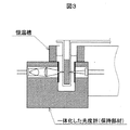
これらの構成部品を設定した位置に保持するため、更には、光軸の調整や組立てを容易にするためには、図3に示すように光度計の構成部品を保持部材に組み立てて一体化しておき、それを恒温槽に取り付けるようにするのが望ましい。 In order to hold these components at the set positions, and to facilitate the adjustment and assembly of the optical axis, the components of the photometer are assembled and integrated into a holding member as shown in FIG. It is desirable to attach it to a thermostat.
しかし、これを恒温槽に取り付けるためには、恒温槽を大きく抉る事が必要となり、恒温水の漏れ防止のシール等が複雑になると言う問題がある。 However, in order to attach this to the thermostatic bath, it is necessary to squeeze the thermostatic bath large, and there is a problem that the seal for preventing leakage of the thermostatic water is complicated.
図4にスリットを除く構成部品を一体化し、恒温槽に取り付けた状態を示す。このようにすれば恒温槽を抉る必要は無く、恒温水を漏らさずに計測光を通す透明部材からなる窓を設ければよい。しかし、光軸調整はスリットを含めて行うことが必要であるため、一体化した部品を恒温槽に取り付けた後に光軸調整が必要となる。光軸は部品の機械的精度で合わせることも可能であるが、図3の保持部材と、それに取り付ける構成部品のみを機械的精度で合わせる場合と比較すると、図4の例では、スリットとスリット以外を一体化した部品をそれぞれ恒温槽に精度良く取り付けることが必要になり、通常直径300mm以上の大きさがある恒温槽に高い精度が必要になると言う問題がある。 FIG. 4 shows a state in which components excluding the slits are integrated and attached to a thermostatic bath. If it does in this way, it is not necessary to pour a thermostat, and what is necessary is just to provide the window which consists of a transparent member which lets measurement light pass, without leaking thermostatic water. However, since it is necessary to adjust the optical axis including the slit, it is necessary to adjust the optical axis after attaching the integrated parts to the thermostat. The optical axis can be aligned with the mechanical accuracy of the parts, but in comparison with the case where only the holding member in FIG. 3 and the components attached thereto are aligned with the mechanical accuracy, in the example of FIG. Therefore, there is a problem that high accuracy is required for a constant temperature bath having a diameter of 300 mm or more.
本発明の目的の一つとしては、装置の小型化、装置設計の自由度向上に寄与する事である。また、光源として、発光ダイオードや半導体レーザといった半導体光源を用いた場合、半導体光源に適した光度計構成で分析装置へ適用することで、さらなる装置の小型化、設計自由度向上することができる。 One of the objects of the present invention is to contribute to the downsizing of the apparatus and the improvement of the degree of freedom in designing the apparatus. Further, when a semiconductor light source such as a light emitting diode or a semiconductor laser is used as the light source, it can be applied to the analyzer with a photometer configuration suitable for the semiconductor light source, thereby further reducing the size of the device and improving the design flexibility.
上記課題を解決するため、光度計として、光源と、光源から照射された光を透過もしくは通過する第1の支持体と、測定試料を入れた反応容器を通過した光を検出する検出器と、検出器を設けた第2の支持体と、測定試料を入れた反応容器が間に挿入されるよう前記第1の支持体と前記第2の支持体は配置され、第1の支持体に設けられ、光源から照射された光を反射して反応容器に光を通過させる第1の反射部と、光源から照射された光を集光して反応容器に光を通過させる集光部を有することを特徴とする。 In order to solve the above problems, as a photometer, a light source, a first support that transmits or passes light emitted from the light source, a detector that detects light that has passed through a reaction container containing a measurement sample, and The first support and the second support are arranged so that the second support provided with the detector and the reaction container containing the measurement sample are inserted therebetween, and are provided on the first support. A first reflecting portion that reflects the light emitted from the light source and passes the light through the reaction vessel; and a light collecting portion that collects the light emitted from the light source and passes the light through the reaction vessel. It is characterized by.
また、光源から照射された光が第1の反射部により概略平行に集光される位置に反応容器が配置されることを特徴とする。 In addition, the reaction container is arranged at a position where the light emitted from the light source is collected approximately in parallel by the first reflecting portion.
反射部としては、平面鏡、放物面鏡、楕円鏡等を用いることができ、それぞれの特徴にあわせた配置をすることができる。 As the reflecting portion, a plane mirror, a parabolic mirror, an elliptical mirror, or the like can be used, and can be arranged according to each feature.
また、発熱が少なく寿命の長い発光ダイオードや半導体レーザを光源に用い、光軸を一直線ではなく折り曲げることで小型化し、光軸を折り曲げる部品と光量を確保するために集光に使用する部品を共通化することで部品点数を減らすと同時に、小型化することと部品点数を減らすこと、及び一体化することで光軸調整を容易にし、より高精度な光度計を達成する。 In addition, light-emitting diodes and semiconductor lasers that generate less heat and have a long life are used as the light source, and the optical axis is bent rather than in a straight line, so that the optical axis is bent and the parts used for condensing to secure the amount of light are common. By reducing the number of parts, the optical axis can be easily adjusted by downsizing, reducing the number of parts, and integration, thereby achieving a highly accurate photometer.
本発明によれば、光軸を反射鏡で曲げることにより、光度計の恒温槽や反応容器ディスクの半径方向の寸法を小さく抑えることが可能になり、装置の小型化に寄与することができる。また、放物面鏡や楕円鏡により光軸を曲げることで集光レンズを不要にし、構成部品点数を低減でき、光軸調整の容易さと相まってコストダウンが可能になる。更には、放物面鏡や楕円鏡を使い分けることで、検出感度に影響する光量を重視した光度計と散乱項目測定の特性を重視した光度計とを使い分けることが可能になり、システムの性能を向上可能にする技術を提供することができる。 According to the present invention, by bending the optical axis with a reflecting mirror, it is possible to reduce the size in the radial direction of the thermostat bath or reaction vessel disk of the photometer, which can contribute to downsizing of the apparatus. Further, by bending the optical axis with a parabolic mirror or an elliptical mirror, a condensing lens is not required, the number of components can be reduced, and the cost can be reduced in combination with the ease of optical axis adjustment. Furthermore, by using different parabolic mirrors and elliptical mirrors, it is possible to use a photometer that emphasizes the amount of light that affects the detection sensitivity and a photometer that emphasizes the characteristics of the scattering item measurement. A technology that enables improvement can be provided.
(実施の形態1)
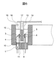
図5は、本発明による液体分析システム用光度計(以下単に光度計と記す。)の構成を示す略図である。本光度計は、LED光源1、前記LED光源1から出射された光を透過もしくは通過する第1の支持体2、前記第1の支持体2に設けられた第1の反射鏡3、同じく前記第1の支持体2に設けられた第1のスリット4、第2のスリット5及び光検出器6を設けた第2の支持体7、前記第1の支持体2及び前記第2の支持体7との間で反応容器13を挟むように配置して溝8を形成し、前記第1の支持体2及び前記第2の支持体7を接続する第3の支持体9、及び、前記第1の支持体2もしくは第3の支持体9により保持されている集光レンズ10から構成される光度計11である。光源として発光ダイオード(LED)を例示しているが、他にも半導体レーザ等を用いることができる。
(Embodiment 1)
FIG. 5 is a schematic diagram showing the configuration of a photometer for a liquid analysis system (hereinafter simply referred to as a photometer) according to the present invention. The photometer includes an
本光度計11による測定試料の分析は、本光度計11を液体分析システムの恒温槽に取り付けて行うため、分析方法の説明に先立ち、液体分析システムの本光度計を取り付ける部分付近の構成と、本光度計との位置関係を説明する。
Since the analysis of the measurement sample by the
図6は、液体分析システムの一部分であり、断面がUの字型をしたリング状の恒温槽12と、反応容器13を前記恒温槽12と同心の円周上に複数並べ持つ反応容器ディスク14を縦に断面して片方のみを示す。反応容器13は、光の入射面、光が透過する内面、及び、光の出射面が平行であり、かつ、光軸に対して直角に配置されている。前記恒温槽12は、その断面がUの字型をした流路15を持ち、前記流路5内を一定温度に保たれた恒温水16が一定の液面高さを保ち循環している。前記反応容器ディスク14は前記恒温槽12の上部で前記恒温槽12と共通の中心軸を中心に回転し、前記反応容器ディスク14に設置されている前記反応容器13は、前記恒温槽12内の前記恒温水16に浸され、前記恒温槽12の前記流路15内を移動する。測定試料17は、測定時に反応容器13に入れられる。光度計11は前記恒温槽12に、前記恒温槽12の下側から前記溝8内部を前記反応容器13が移動可能な位置に取り付けられている。また、前記光度計11は一個もしくは前記恒温槽12と同心の円周上に複数配置されている。
FIG. 6 shows a part of the liquid analysis system, a ring-shaped
本光度計11による測定試料の分析は、前記のように前記恒温槽12に光度計11が取り付けられ、前記反応ディスク14が回転し、目的の前記測定試料17が入った前記反応容器13が光度計11の溝8の位置に移動してきたときに行われる。
In the analysis of the measurement sample by the
分析時は、前記LED光源1から出射した光を前記集光レンズ10により前記反応容器13内の前記測定試料17位置に集光し、前記第1の反射鏡3で反射して略90度光軸を曲げ、前記第1のスリット4により照射領域を一定に制御して照射する。
At the time of analysis, the light emitted from the LED
尚、通常恒温水16には、雑菌の繁殖等を防止するため、アルカリもしくは酸性の液体が用いられる。そのため、第1の支持体2、第1の反射鏡3、第1のスリット4、第2のスリット5、及び、第3の支持体9は、アルカリ及び酸性の液体に耐性を持つ、ガラス、金属、及びもしくは樹脂を用いており、LED光源1、光検出器6、及び、集光レンズ10等には恒温水16が入り込まないようにシールされている。
The
本光度計が対象としている、液体分析システムによる試料の測定原理は、次の通りである。 The measurement principle of the sample by the liquid analysis system targeted by this photometer is as follows.
前記測定試料17には、分析項目により選択された試薬が混合されており、分析対象成分と反応し、前記分析対象成分が含まれる割合に合わせ、特定波長の光を吸収する。そのため、前記LED光源1から出射する光の波長は、分析項目により選択された波長を使用する。前記測定試料17に照射された光は、前述のように前記分析対象成分量により吸収され、前記第2のスリット5により迷光が取り除かれた上で前記光検出器6に照射される。前記光検出器6に照射された光は、前記光検出器6により電気信号に変換され、その信号量を解析することによって前記測定試料17に含まれる分析対象成分の量を知ることができる。通常このような計測方法を吸光度計測と呼ぶ。
The
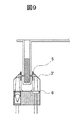
本光度計11によれば、前記図1から図4に示すような光度計に対し、光軸を第1の反射鏡3で曲げることと、光検出器6を第2のスリット5の直後に配置することにより、光度計の前記恒温槽12や前記反応容器ディスク14の半径方向の寸法を小さく抑えることが可能であるため、図7のように前記反応容器ディスク14の円周上に複数並んだ反応容器13と光度計11を更に同心円状に複数列配置することが可能となり、装置の大きさを大きく変えずに処理能力を向上、もしくは、処理能力を変えずに装置を小型化することも可能となる。また、複数配置した光度計それぞれの波長を異ならせることにより、複数項目の分析を同時に行うことができる。
According to the
前記図5で示す例では、前記第1の支持体2は光透過部材を用いて説明しており、第1の反射鏡3はその外面を反射面として用いているが、図8に示すように、前記第1の支持体2に不透明部材を用い、その内部に光を通す空間18を設けた構成も考えられる。これにより部品製造方法の選択肢が増し、コスト低下が期待できる。
In the example shown in FIG. 5, the
また、前記図5では第2のスリット5の直後に光検出器6を配置しているが、第2のスリット5と光検出器6が近すぎると迷光を検出しやすくなるため、図9に示すように第2の反射鏡3’で光軸を下方に曲げる事も可能である。
(実施の形態2)
図10は、本発明による光度計の構成を示す略図である。本光度計は、LED光源21、前記LED光源21から出射された光を透過もしくは通過する第1の支持体22、前記第1の支持体22に設けられた第1の反射鏡23、同じく前記第1の支持体22に設けられた第1のスリット24、第2のスリット25及び光検出器26を設けた第2の支持体27、及び、前記第1の支持体22及び前記第2の支持体27との間で溝28を形成し、前記第1の支持体22及び前記第2の支持体27を接続する第3の支持体29から構成される光度計30である。光源として発光ダイオード(LED)を例示しているが、他にも半導体レーザ等を用いることができる。
In FIG. 5, the
(Embodiment 2)
FIG. 10 is a schematic diagram showing the configuration of a photometer according to the present invention. The photometer includes an
第1の反射鏡23は放物面鏡の一部を切り出した形状であり、放物面鏡の軸は概略水平に設定され、かつ、第1のスリット24と第2のスリット25の中心同士を結ぶ直線、つまり水平部分の光軸31と平行に設定されている。また、放物面鏡の焦点位置には前記LED光源21が配置されており、前記LED光源21から出射される光の光軸32は、概略鉛直に設定され、前記第1の反射鏡23で反射し直角に曲げられ、前記水平部分の光軸31となる。
The first reflecting
本光度計30による測定試料の分析は、本光度計30を液体分析システムの恒温槽に取り付けて行う。液体分析システムの本光度計を取り付ける部分付近の構成と、本光度計との位置関係は実施の形態1と同じであるため割愛する。
The analysis of the measurement sample by the
本光度計30による測定試料の分析は、実施の形態1と同様に、前記恒温槽12に前記光度計30が取り付けられ、前記反応ディスク14が回転し、目的の前記測定試料17が入った前記反応容器13が前記光度計30の前記溝28の位置に移動してきた時に行われる。
In the analysis of the measurement sample by the
分析時は、前記LED光源21から出射した光を第1の反射鏡23により反射し、前記第1のスリット24により照射領域を一定に制御して、前記反応容器13内の前記測定試料17に照射する。前記第1の反射鏡23は放物面鏡であり、その焦点に配置されている前記LED光源21から出射する光は、前記第1の反射鏡23で反射して曲げられた後、水平部分の光軸31と平行に整形、かつ、平行に集光される。厳密に言えば、LED光源21は完全な点光源ではないために、放物面鏡の焦点からずれた位置から出射される光は前記水平部分の光軸31と完全な平行にはならないが、放物面鏡により第1のスリット24と第2のスリット25の両方のスリットを通過する光量を概略平行にして集光できればよい。
At the time of analysis, the light emitted from the LED
尚、通常恒温水16には、雑菌の繁殖等を防止するため、アルカリもしくは酸性の液体が用いられる。そのため、第1の支持体22、第1の反射鏡23、第1のスリット24、第2のスリット25、及び、第3の支持体29は、アルカリ及び酸性の液体に耐性を持つ、ガラス、金属、及びもしくは樹脂を用いており、LED光源21、及び、光検出器26等には恒温水16が入り込まないようにシールされている。
The
本光度計が対象としている、液体分析システムによる試料の測定原理は、実施の形態1と同じであるため割愛する。 The measurement principle of the sample by the liquid analysis system, which is the object of the present photometer, is the same as in the first embodiment, and is omitted.
本光度計30においても、前記図1から図4に示すような光度計に対し、光度計の前記恒温槽12や前記反応容器ディスク14の半径方向の寸法を小さく抑えることが可能であるため、図7と同様に、前記反応容器ディスク14の円周上に複数並んだ反応容器13を更に同心円状に複数列配置することが可能となり、装置の大きさを変えずに処理能力を向上、もしくは、処理能力を変えずに装置を小型化することも可能となる。
In the
また、実施の形態1では、光軸を曲げるための第1の反射鏡3と光を集めるための集光レンズ10が必要であったが、本実施の形態の光度計30では、第1の反射鏡23が集光と反射を兼ねるため部品点数が少なくなり、光軸調整が容易になるという効果がある。
In the first embodiment, the first reflecting
前記図10で示す例では、前記第1の支持体22は光透過部材を用いて説明しており、第1の反射鏡23はその外面を反射面として用いているが、実施の形態1と同様に、図11に示すように、前記第1の支持体22に不透明部材を用い、その内部に光を通す空間33を設けた構成も考えられる。これにより部品製造方法の選択肢が増し、コスト低下が期待できる。
In the example shown in FIG. 10, the
本光度計30においては、前述のように試料に照射される光が概略平行に集光されているため、散乱光の測定に有利である。すなわち、図12に示すように、反応容器13内の測定試料17が散乱測定を目的とする項目の場合、光検出器26に照射される光は散乱によって減少した透過光34を受光することにより失った散乱光35の量を算出するが、この時、散乱光35が光検出器26に入り込まないのが望ましい。散乱光35は、照射される光が特定の角度分布で出射される。そのため、実施の形態1に示す光度計11で散乱光を測定する場合、反応容器13内の測定試料17には、図13のように角度を持って光が照射される場合があるため、散乱光35が光検出器26に入り易くなり、精度の良い散乱測定を行いにくい場合があるのに対し、本光度計30の場合は、試料に照射される光が概略平行に集光されているため、散乱光が光検出器26に入りにくくなり、散乱光の測定に有利である。
In the
また、前記図10では第2のスリット25の直後に光検出器26を配置しているが、第2のスリット25と光検出器26が近すぎると迷光を検出しやすくなるため、図14に示すように第2の反射鏡23’で光軸を下方に曲げる事も可能である。この場合、第2の反射鏡23’は放物面鏡でなくとも良い。更には、図15に示すように、LED光源21から出射される光を集光レンズ10’により放物面鏡の焦点位置に結像することでも良い。
(実施の形態3)
図16は、本発明による光度計の構成を示す略図である。本光度計は、LED光源41、前記LED光源41から出射された光を透過もしくは通過する第1の支持体42、前記第1の支持体42に設けられた第1の反射鏡43、同じく前記第1の支持体42に設けられた第1のスリット44、第2のスリット45及び光検出器46を設けた第2の支持体47、及び、前記第1の支持体42及び前記第2の支持体47との間で溝48を形成し、前記第1の支持体42及び前記第2の支持体47を接続する第3の支持体49から構成される光度計50である。光源として発光ダイオード(LED)を例示しているが、他にも半導体レーザ等を用いることができる。
In FIG. 10, the
(Embodiment 3)
FIG. 16 is a schematic diagram showing the configuration of a photometer according to the present invention. The photometer includes an
第1の反射鏡43は楕円鏡の一部を切り出した形状であり、楕円鏡の第1の焦点51にLED光源41を配置し、第2の焦点52が反応容器13内の測定試料17内を透過する光軸長さ方向の概略中心位置に来るように定義した楕円鏡である。さらに、前記LED光源41から出射される光の光軸53は、概略鉛直に設定され、前記第1の反射鏡43で反射し直角に曲げられ、水平部分の光軸54となる。LED光源41から出射される光の光軸53と検体を通過する水平部分の光軸54を直角に配置するには、出射される光の光軸53と検体を通過する水平部分の光軸54に対し、基準楕円の長軸が45度になるようにし、基準楕円の第1の焦点51と第2の焦点52の距離が、基準楕円の短軸長さと同じになるようにすれば良いが、反応容器13の光の入射面に光軸が直角に入射することが重要であり、前記第1の反射鏡43で反射し直角に曲げる事は必ずしも重要ではなく、直角に曲げない場合は、出射される光の光軸53が鉛直ではなくなる。
The first reflecting
本光度計50による測定試料の分析は、本光度計50を液体分析システムの恒温槽に取り付けて行う。液体分析システムの本光度計を取り付ける部分付近の構成と、本光度計との位置関係は実施の形態1と同じであるため割愛する。
The analysis of the measurement sample by the
本光度計50による測定試料の分析は、実施の形態1と同様に、前記恒温槽12に前記光度計50が取り付けられ、前記反応ディスク14が回転し、目的の前記測定試料17が入った前記反応容器13が前記光度計50の前記溝48の位置に移動してきた時に行われる。
In the analysis of the measurement sample by the
分析時は、前記LED光源41から出射した光を第1の反射鏡43により反射し、前記第1のスリット44により照射領域を一定に制御して、前記反応容器13内の前記測定試料17に照射する。前記第1の反射鏡43は楕円鏡であり、その第1の焦点51に配置されている前記LED光源41から出射する光は、前記第1の反射鏡43で反射して曲げられた後、第2の焦点52の位置である反応容器13内の測定試料17内を透過する光軸長さ方向の概略中心位置に集光される。
At the time of analysis, the light emitted from the LED
尚、通常恒温水16には、雑菌の繁殖等を防止するため、アルカリもしくは酸性の液体が用いられる。そのため、第1の支持体42、第1の反射鏡43、第1のスリット44、第2のスリット45、及び、第3の支持体49は、アルカリ及び酸性の液体に耐性を持つ、ガラス、金属、及びもしくは樹脂を用いており、LED光源41、及び、光検出器46等には恒温水16が入り込まないようにシールされている。
The
本光度計が対象としている、液体分析システムによる試料の測定原理は、実施の形態1と同じであるため割愛する。 The measurement principle of the sample by the liquid analysis system, which is the object of the present photometer, is the same as in the first embodiment, and is omitted.
本光度計50においても、前記図1から図4に示すような光度計に対し、光度計の前記恒温槽12や前記反応容器ディスク14の半径方向の寸法を小さく抑えることが可能であるため、図7と同様に、前記反応容器ディスク14の円周上に複数並んだ反応容器13を更に同心円状に複数列配置することが可能となり、装置の大きさを変えずに処理能力を向上、もしくは、処理能力を変えずに装置を小型化することも可能となる。
In the
また、実施の形態1では、光軸を曲げるための第1の反射鏡3と光を集めるための集光レンズ10が必要であったが、本実施の形態の光度計50では、第1の反射鏡43が集光と反射を兼ねるため部品点数が少なくなり、光軸調整が容易になるという効果がある。
In the first embodiment, the first reflecting
前記図16で示す例では、前記第1の支持体42は光透過部材を用いて説明しており、第1の反射鏡43はその外面を反射面として用いているが、実施の形態1と同様に、図17に示すように、前記第1の支持体42に不透明部材を用い、その内部に光を通す空間55を設けた構成も考えられる。これにより部品製造方法の選択肢が増し、コスト低下が期待できる。
In the example shown in FIG. 16, the
本光度計50においては、前述のように試料に照射される光は反応容器13内の測定試料17内を透過する光軸長さ方向の概略中心位置に集光されるため、散乱光の測定には実施の形態1、2と比較すると不利な点もあるが、第1のスリット44、第2のスリット45を通過後に光検出器46で検出する受光量は平行光の場合に比べて多くなる。それは実施の形態1においても同様であるが、光源からの光を平行光にする場合、光源からずれて出射する光は第1のスリットと第2のスリットの両方は通りにくくなるが、光源からの光を集光する場合は平行光にする場合に比べて光源からずれて出射する光を集光しやすいためである。
In the
図18に、第1の反射鏡を放物面鏡にした場合と、第1の反射鏡を楕円鏡にした場合とで比較シミュレーションして算出した受光量の割合を示す。図18(a)は放物面鏡の場合、図18(b)は楕円鏡の場合を示す。どちらも略同じ条件になるような出射光量、大きさにしてシミュレーションした結果、受光光量は、放物面鏡の場合を1とすると楕円鏡の場合が1.27であり、楕円鏡の光量の方が多いことが分かった。 FIG. 18 shows the ratio of the amount of received light calculated by comparison simulation between the case where the first reflecting mirror is a parabolic mirror and the case where the first reflecting mirror is an elliptical mirror. 18A shows the case of a parabolic mirror, and FIG. 18B shows the case of an elliptic mirror. As a result of simulating the emitted light quantity and size so that both conditions are almost the same, the received light quantity is 1.27 for the elliptical mirror when the parabolic mirror is 1, and the light quantity of the elliptical mirror is I found out that there were more.
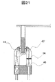
つまり、大きな光量を必要とする高感度の測定には実施の形態1のようにレンズで集光するか、本実施の形態3のように楕円鏡等で集光するのが適しており、散乱光測定には、実施の形態2のように平行に集光するのが適しており、用途に応じて使い分けるのが良い。また、前記図16では第2のスリット45の直後に光検出器46を配置しているが、第2のスリット45と光検出器46が近すぎると迷光を検出しやすくなるため、図19、図20に示すように第2の反射鏡43’で光軸を下方に曲げる事も可能である。この場合、第2の反射鏡43’は楕円鏡でなくとも良い。更には、図20に示すように、LED光源41から出射される光を集光レンズ10”により楕円鏡の第1の焦点51に結像することでも良く、散乱光測定時の迷光の影響をより低減するために、図21に示すように、第3のスリット56を設けることも可能である。
(実施の形態4)
図22は本実施の形態による液体分析システム60を示す略図である。液体分析システム60は、恒温槽12、反応容器13を前記恒温槽12と同心の円周上に複数並べ持つ反応容器ディスク14、測定試料17を入れた検体容器61、複数の検体容器61を搬送するラック62、検体容器61内の測定試料17を一定量吸引して反応容器13に分注する検体ディスペンサ63、分析項目により選択可能な複数の試薬が入った試薬ボトル64を収めた試薬ディスク65、試薬ボトル64から一定量の試薬を吸引して反応容器13に分注する試薬ディスペンサ66、反応容器13に分注された測定試料17と試薬を撹拌する撹拌部67、分析が終了した後の反応容器13を洗浄するための洗浄部68、そして、前記実施の形態1、前記実施の形態2、前記実施の形態3いずれかによる光度計を、1つ又は複数並べた計測部69等から構成されている。
That is, for high-sensitivity measurement that requires a large amount of light, it is appropriate to collect light with a lens as in the first embodiment or with an elliptical mirror as in the third embodiment. For light measurement, it is suitable to collect light in parallel as in the second embodiment, and it is preferable to use the light according to the application. In FIG. 16, the
(Embodiment 4)
FIG. 22 is a schematic diagram showing a
図22において、反応容器ディスク14は測定試料17の分注、試薬の分注、反応容器13に分注された測定試料17と試薬の撹拌、及び、反応容器13の洗浄の動作時に停止し、同動作を次の反応容器13で行うために回転移動する。また、ラック62は複数の検体容器61を搬送するために直進移動し、試薬ディスク65は、所望の試薬ボトル64を試薬ディスペンサ66が吸引できる位置に回転移動する。通常、反応容器ディスク14は一定方向に回転し、測定試料17と試薬が分注され、撹拌されて測定可能になった反応容器13内の測定試料17が計測部69の位置に来たときに所望の光度計で計測される。
In FIG. 22, the
液体分析システム60では、吸光度計測を行う場合と、吸光度計測でも散乱特性を重視する計測を行う場合とが混在するため、計測部69には、前記光度計11、前記光度計30、前記光度計50を目的に応じて複数混在させ、配置するようにしてもよい。また、複数配置した光度計それぞれの波長を異ならせることにより、複数項目の分析を同時に行ってもよい。
In the
その際、配置している光度計の配置間隔は、反応容器ディスク14に複数配置されている反応容器13の配置間隔と同じになっており、複数の測定試料17を複数の光度計で、同じタイミングで計測できるようにすることで、データ処理や装置制御の煩雑さを緩和し、また同じ条件での測定をすることができる。
At this time, the arrangement interval of the arranged photometers is the same as the arrangement interval of the plurality of
1…LED光源、2…第1の支持体、3…第1の反射鏡、3‘…第2の反射鏡、4…第1のスリット、5…第2のスリット、6…光検出器、7…第2の支持体、8…溝、9…第3の支持体、10…集光レンズ、10‘…集光レンズ、11…光度計、12…恒温槽、13…反応容器、14…反応容器ディスク、15…流路、16…恒温水、17…測定試料、18…光を通す空間、21…LED光源、22…第1の支持体、23…第1の反射鏡、23‘…第2の反射鏡、24…第1のスリット、25…第2のスリット、26…光検出器、27…第2の支持体、28…溝、29…第3の支持体、30…光度計、31…水平部分の光軸、32…出射される光の光軸、33…光を通す空間、34…透過光、35…散乱光、41…LED光源、42…第1の支持体、43…第1の反射鏡、43‘…第2の反射鏡、44…第1のスリット、45…第2のスリット、46…光検出器、47…第2の支持体、48…溝、49…第3の支持体、50…光度計、51…第1の焦点、52…第2の焦点、53…出射される光の光軸、54…水平部分の光軸、55…光を通す空間、56…第3のスリット、60…液体分析システム、61…検体容器、62…ラック、63…ディスペンサ、64…試薬ボトル、65…試薬ディスク、66…試薬ディスペンサ、67…撹拌部、68…洗浄部、69…計測部。
DESCRIPTION OF
Claims (12)
前記光源から照射された光を透過もしくは通過する第1の支持体と、
測定試料を入れた反応容器を通過した光を検出して、前記検出した光を電気信号に変換する検出器と、
前記検出器を設けた第2の支持体と、
測定試料を入れた反応容器が間に挿入されるよう前記第1の支持体と前記第2の支持体とを接続する第3の支持体と、
前記光源から照射された光を集光させる集光部と、
前記第1の支持体に設けられ、前記集光部で集光された光を反射して前記反応容器に光を通過させる第1の反射部と、を有し、
前記第1の反射部は放物面鏡であり、前記光源は前記放物面鏡の焦点位置に配置され、
前記光源から照射された光が前記第1の反射部により概略平行に集光される位置に前記反応容器が配置され、前記集光部は前記放物面鏡が兼ねており、
前記光源は前記第1の支持体もしくは第3の支持体の内部に設けられ、
前記第1の支持体は、前記第1の反射部で反射された光を通過させる第1のスリットを有し、前記第2の支持体は、前記反応容器を通過した光を通過させる第2のスリットを有し、
前記第2のスリットと前記検出器との光路間に第2の反射部を配置することで前記第2のスリットと前記検出器とを離隔するとともに前記第2のスリットから出射する光の光路を前記検出器に向けて変換し、前記第2のスリットと前記検出器との間で生じる迷光の前記検出器による受光量を低減することを特徴とする光度計。 A light source;
A first support that transmits or passes light emitted from the light source;
A detector that detects light that has passed through a reaction vessel containing a measurement sample and converts the detected light into an electrical signal;
A second support provided with the detector;
A third support for connecting the first support and the second support so that a reaction vessel containing a measurement sample is inserted therebetween;
A light collecting unit for collecting light emitted from the light source;
A first reflecting portion provided on the first support, which reflects the light collected by the light collecting portion and allows the light to pass through the reaction vessel;
The first reflecting portion is a parabolic mirror, and the light source is disposed at a focal position of the parabolic mirror;
The reaction vessel is arranged at a position where the light emitted from the light source is collected approximately in parallel by the first reflecting unit, and the collecting unit also serves as the parabolic mirror,
The light source is provided inside the first support or the third support ,
The first support has a first slit through which the light reflected by the first reflecting portion passes, and the second support has a second through which the light that has passed through the reaction vessel passes. Have slits,
An optical path of light emitted from the second slit while separating the second slit and the detector by disposing a second reflecting portion between the optical paths between the second slit and the detector. A photometer that converts toward the detector and reduces the amount of stray light received between the second slit and the detector by the detector .
前記光源から照射された光を透過もしくは通過する第1の支持体と、
測定試料を入れた反応容器を通過した光を検出して、前記検出した光を電気信号に変換
する検出器と、
前記検出器を設けた第2の支持体と、
測定試料を入れた反応容器が間に挿入されるよう前記第1の支持体と前記第2の支持体とを接続する第3の支持体と、
前記光源から照射された光を集光させる集光部と、
前記第1の支持体に設けられ、前記集光部で集光された光を反射して前記反応容器に光を通過させる第1の反射部と、を有し、
前記第1の反射部は楕円鏡であり、前記楕円鏡の第1の焦点位置に前記光源を配置し、
前記楕円鏡の第2の焦点位置に、前記反応容器の前記光が通過する長さの概略中心位置を配置し、
前記光源から照射された光が前記第1の反射部により集光される位置に前記反応容器が配置され、前記集光部は前記楕円鏡が兼ねており、
前記光源は、前記第1の支持体もしくは第3の支持体の内部に設けられ、
前記第1の支持体は、前記第1の反射部で反射された光を通過させる第1のスリットを有し、前記第2の支持体は、前記反応容器を通過した光を通過させる第2のスリットを有し、
前記第2のスリットと前記検出器との光路間に第2の反射部を配置することで前記第2のスリットと前記検出器とを離隔するとともに前記第2のスリットから出射する光の光路を前記検出器に向けて変換し、前記第2のスリットと前記検出器との間で生じる迷光の前記検出器による受光量を低減することを特徴とする光度計。 A light source;
A first support that transmits or passes light emitted from the light source;
A detector that detects light that has passed through a reaction vessel containing a measurement sample and converts the detected light into an electrical signal;
A second support provided with the detector;
A third support for connecting the first support and the second support so that a reaction vessel containing a measurement sample is inserted therebetween;
A light collecting unit for collecting light emitted from the light source;
A first reflecting portion provided on the first support, which reflects the light collected by the light collecting portion and allows the light to pass through the reaction vessel;
The first reflecting portion is an elliptical mirror, the light source is disposed at a first focal position of the elliptical mirror,
The approximate center position of the length through which the light of the reaction vessel passes is arranged at the second focal position of the elliptical mirror,
The light emitted from the light source is the reaction vessel is disposed in a position that is by Ri condensing said first reflecting portion, the condensing section serves also as the elliptical mirror,
The light source is provided inside of the first support or a third support,
The first support has a first slit through which the light reflected by the first reflecting portion passes, and the second support has a second through which the light that has passed through the reaction vessel passes. Have slits,
An optical path of light emitted from the second slit while separating the second slit and the detector by disposing a second reflecting portion between the optical paths between the second slit and the detector. A photometer that converts toward the detector and reduces the amount of stray light received between the second slit and the detector by the detector .
前記第2の集光部は前記第2の放物面鏡が兼ね、前記第2の放物面鏡の焦点位置に前記検出器を配置したことを特徴とする光度計。 The photometer according to claim 4 , wherein the second reflecting portion is a second parabolic mirror,
The second condensing unit also serves as the second parabolic mirror, and the detector is disposed at a focal position of the second parabolic mirror.
Priority Applications (1)
| Application Number | Priority Date | Filing Date | Title |
|---|---|---|---|
| JP2015099779A JP6051264B2 (en) | 2008-12-24 | 2015-05-15 | Photometer |
Applications Claiming Priority (3)
| Application Number | Priority Date | Filing Date | Title |
|---|---|---|---|
| JP2008326796 | 2008-12-24 | ||
| JP2008326796 | 2008-12-24 | ||
| JP2015099779A JP6051264B2 (en) | 2008-12-24 | 2015-05-15 | Photometer |
Related Parent Applications (1)
| Application Number | Title | Priority Date | Filing Date |
|---|---|---|---|
| JP2010543846A Division JP5780761B2 (en) | 2008-12-24 | 2009-12-22 | Analytical system with photometer |
Publications (2)
| Publication Number | Publication Date |
|---|---|
| JP2015143720A JP2015143720A (en) | 2015-08-06 |
| JP6051264B2 true JP6051264B2 (en) | 2016-12-27 |
Family
ID=42287251
Family Applications (2)
| Application Number | Title | Priority Date | Filing Date |
|---|---|---|---|
| JP2010543846A Expired - Fee Related JP5780761B2 (en) | 2008-12-24 | 2009-12-22 | Analytical system with photometer |
| JP2015099779A Expired - Fee Related JP6051264B2 (en) | 2008-12-24 | 2015-05-15 | Photometer |
Family Applications Before (1)
| Application Number | Title | Priority Date | Filing Date |
|---|---|---|---|
| JP2010543846A Expired - Fee Related JP5780761B2 (en) | 2008-12-24 | 2009-12-22 | Analytical system with photometer |
Country Status (5)
| Country | Link |
|---|---|
| US (1) | US8675187B2 (en) |
| JP (2) | JP5780761B2 (en) |
| CN (1) | CN102265140B (en) |
| DE (1) | DE112009003827T5 (en) |
| WO (1) | WO2010073604A1 (en) |
Families Citing this family (22)
| Publication number | Priority date | Publication date | Assignee | Title |
|---|---|---|---|---|
| AT510631B1 (en) * | 2010-10-20 | 2013-01-15 | Scan Messtechnik Ges M B H | SPECTROMETER |
| WO2012066893A1 (en) * | 2010-11-18 | 2012-05-24 | 株式会社日立ハイテクノロジーズ | Automatic analysis device |
| JP5481402B2 (en) | 2011-01-17 | 2014-04-23 | 株式会社日立ハイテクノロジーズ | Automatic analyzer |
| CN103210297B (en) * | 2011-01-21 | 2016-05-04 | 株式会社日立高新技术 | Automatic analysing apparatus |
| CN102590168A (en) * | 2012-02-16 | 2012-07-18 | 无锡迈通科学仪器有限公司 | Light emitting diode-based fluorescent microorganism detector |
| JP5957294B2 (en) * | 2012-05-29 | 2016-07-27 | 浜松ホトニクス株式会社 | Prism member, terahertz wave spectrometer, and terahertz wave spectrometer |
| JP5946776B2 (en) * | 2013-01-18 | 2016-07-06 | 株式会社日立ハイテクノロジーズ | Automatic analyzer |
| US9857219B2 (en) * | 2013-08-27 | 2018-01-02 | Hitachi High-Technologies Corporation | Nucleic acid analysis device and diagnosis method |
| JP6492838B2 (en) * | 2015-03-23 | 2019-04-03 | セイコーエプソン株式会社 | Spectroscopic apparatus, image forming apparatus, and spectral measuring method |
| JP6437390B2 (en) * | 2015-06-30 | 2018-12-12 | 株式会社日立ハイテクノロジーズ | Automatic analyzer |
| JP6659313B2 (en) * | 2015-11-13 | 2020-03-04 | 古野電気株式会社 | Reaction measurement unit and analyzer |
| CN109477775B (en) * | 2016-07-21 | 2022-05-13 | 西门子医疗保健诊断公司 | Alignment system for rows of cups on clinical chemistry instruments |
| JP6637407B2 (en) * | 2016-12-27 | 2020-01-29 | 株式会社日立ハイテクノロジーズ | Automatic analyzer |
| RU2018134774A (en) * | 2016-12-28 | 2021-01-29 | КАБУСИКИ КАЙСЯ Мираи Дженомикс | ANALYSIS DEVICE |
| US11635443B2 (en) | 2017-07-14 | 2023-04-25 | Meon Medical Solutions Gmbh & Co Kg | Automatic analyzer and method for carrying out chemical, biochemical, and/or immunochemical analyses |
| EP3769842A1 (en) | 2017-07-14 | 2021-01-27 | Meon Medical Solutions GmbH & Co. KG | Automatic analyzer and method for performing chemical, biochemical and / or immunochemical analyses |
| CN108152211A (en) * | 2018-01-17 | 2018-06-12 | 睿科仪器(厦门)有限公司 | A kind of device and method of automatic decision sample liquids color |
| JP7327818B2 (en) * | 2018-04-23 | 2023-08-16 | メオン・メディカル・ソリューションズ・ゲー・エム・ベー・ハー・ウント・コー・カー・ゲー | Automatic analyzer and optical measuring method for obtaining a measuring signal from a liquid medium |
| WO2019204840A1 (en) | 2018-04-23 | 2019-10-31 | Meon Medical Solutions Gmbh & Co Kg | Optical measuring unit and optical measuring method for obtaining measurement signals of fluid media |
| JP7194580B2 (en) * | 2018-12-19 | 2022-12-22 | 株式会社トプコン | spectrometer |
| WO2021041745A1 (en) * | 2019-08-28 | 2021-03-04 | Siemens Healthcare Diagnostics Inc. | Photometer optical coupling for a dual incubation ring using a periscope design |
| JP2023069603A (en) * | 2021-11-08 | 2023-05-18 | 株式会社日立ハイテク | Biological sample measurement device |
Family Cites Families (18)
| Publication number | Priority date | Publication date | Assignee | Title |
|---|---|---|---|---|
| JPS60114743A (en) | 1983-11-26 | 1985-06-21 | Toshiba Corp | Automatic chemical analyzer using prism for measuring light in liquid |
| US4935875A (en) * | 1987-12-02 | 1990-06-19 | Data Chem, Inc. | Chemical analyzer |
| JPH0875648A (en) | 1994-06-30 | 1996-03-22 | Opt Kk | Measuring device of quantity of light transmitted through liquid |
| JP3533502B2 (en) * | 1994-10-14 | 2004-05-31 | 株式会社日立製作所 | Automatic chemical analyzer |
| GB9424218D0 (en) | 1994-11-30 | 1995-01-18 | Zynocyte Ltd | Apparatus for analysing blood and other samples |
| JP3749321B2 (en) | 1996-10-28 | 2006-02-22 | 株式会社日立製作所 | Automatic analyzer |
| JP4120050B2 (en) * | 1998-07-16 | 2008-07-16 | 株式会社ニコン | Optical property detector |
| JP4168543B2 (en) * | 1998-10-08 | 2008-10-22 | 株式会社ニコン | Optical property measurement unit |
| JP3964291B2 (en) | 2002-09-06 | 2007-08-22 | 富士フイルム株式会社 | Analytical instrument |
| JP4086182B2 (en) | 2002-10-09 | 2008-05-14 | オリンパス株式会社 | Spectroscope, confocal optical system using the same, and scanning optical microscope |
| JP4753645B2 (en) * | 2005-07-11 | 2011-08-24 | ベックマン コールター, インコーポレイテッド | Automatic analyzer |
| JP2007155477A (en) | 2005-12-05 | 2007-06-21 | Fujikura Ltd | Surface plasmon resonance sensor |
| JP4696934B2 (en) | 2006-01-27 | 2011-06-08 | 和光純薬工業株式会社 | Analysis equipment |
| JP2007218633A (en) | 2006-02-14 | 2007-08-30 | Olympus Corp | Autoanalyzer |
| JP4897308B2 (en) | 2006-02-20 | 2012-03-14 | ベックマン コールター, インコーポレイテッド | Analysis equipment |
| JP2007225339A (en) | 2006-02-21 | 2007-09-06 | Olympus Corp | Analyzer |
| JP2008134128A (en) | 2006-11-28 | 2008-06-12 | Canon Inc | Apparatus and method for inspecting surface condition |
| JP2007304103A (en) | 2007-06-18 | 2007-11-22 | Olympus Corp | Spectroscope and confocal optical system using it, and scanning optical microscope |
-
2009
- 2009-12-22 WO PCT/JP2009/007096 patent/WO2010073604A1/en active Application Filing
- 2009-12-22 JP JP2010543846A patent/JP5780761B2/en not_active Expired - Fee Related
- 2009-12-22 US US13/141,378 patent/US8675187B2/en not_active Expired - Fee Related
- 2009-12-22 DE DE112009003827T patent/DE112009003827T5/en not_active Withdrawn
- 2009-12-22 CN CN200980152349.4A patent/CN102265140B/en not_active Expired - Fee Related
-
2015
- 2015-05-15 JP JP2015099779A patent/JP6051264B2/en not_active Expired - Fee Related
Also Published As
| Publication number | Publication date |
|---|---|
| JP5780761B2 (en) | 2015-09-16 |
| JPWO2010073604A1 (en) | 2012-06-07 |
| CN102265140B (en) | 2014-09-10 |
| CN102265140A (en) | 2011-11-30 |
| DE112009003827T5 (en) | 2012-06-06 |
| WO2010073604A1 (en) | 2010-07-01 |
| US20110255090A1 (en) | 2011-10-20 |
| JP2015143720A (en) | 2015-08-06 |
| US8675187B2 (en) | 2014-03-18 |
Similar Documents
| Publication | Publication Date | Title |
|---|---|---|
| JP6051264B2 (en) | Photometer | |
| JP5908954B2 (en) | Automatic analyzer | |
| CN101482572B (en) | Automatic analysis apparatus and automatic analysis method | |
| JP2007322324A (en) | Analyzer | |
| CN101287980A (en) | System for optically analyzing a substance | |
| US9285311B2 (en) | System for performing scattering and absorbance assays | |
| US11668647B2 (en) | Illumination unit with multiple light sources for generating a uniform illumination spot | |
| JPH11511560A (en) | Analyzer | |
| WO2016006362A1 (en) | Automatic analysis device | |
| JP5865713B2 (en) | Automatic analyzer | |
| JP3533502B2 (en) | Automatic chemical analyzer | |
| JP6710535B2 (en) | Automatic analyzer | |
| JP2008051822A (en) | Chemical analyzer | |
| TWI344542B (en) | ||
| JP2007218633A (en) | Autoanalyzer | |
| US20240085311A1 (en) | Light Source and Automatic Analyzer | |
| JP2003279585A (en) | Automatic chemical analysis apparatus | |
| JP2003279481A (en) | Automatic chemical analysis device | |
| JP5017444B2 (en) | Chemical analyzer | |
| JP2015175667A (en) | Automatic analysis apparatus | |
| JP2020016521A (en) | Autoanalyzer, method, and reaction vessel | |
| JP2021047082A (en) | Automatic analysis device | |
| JP2007225336A (en) | Autoanalyzer |
Legal Events
| Date | Code | Title | Description |
|---|---|---|---|
| A621 | Written request for application examination |
Free format text: JAPANESE INTERMEDIATE CODE: A621 Effective date: 20150515 |
|
| A131 | Notification of reasons for refusal |
Free format text: JAPANESE INTERMEDIATE CODE: A131 Effective date: 20160329 |
|
| A521 | Request for written amendment filed |
Free format text: JAPANESE INTERMEDIATE CODE: A523 Effective date: 20160526 |
|
| TRDD | Decision of grant or rejection written | ||
| A01 | Written decision to grant a patent or to grant a registration (utility model) |
Free format text: JAPANESE INTERMEDIATE CODE: A01 Effective date: 20161101 |
|
| A61 | First payment of annual fees (during grant procedure) |
Free format text: JAPANESE INTERMEDIATE CODE: A61 Effective date: 20161128 |
|
| R150 | Certificate of patent or registration of utility model |
Ref document number: 6051264 Country of ref document: JP Free format text: JAPANESE INTERMEDIATE CODE: R150 |
|
| LAPS | Cancellation because of no payment of annual fees |