JP6051127B2 - refrigerator - Google Patents
refrigerator Download PDFInfo
- Publication number
- JP6051127B2 JP6051127B2 JP2013181315A JP2013181315A JP6051127B2 JP 6051127 B2 JP6051127 B2 JP 6051127B2 JP 2013181315 A JP2013181315 A JP 2013181315A JP 2013181315 A JP2013181315 A JP 2013181315A JP 6051127 B2 JP6051127 B2 JP 6051127B2
- Authority
- JP
- Japan
- Prior art keywords
- fitting hole
- hinge
- door
- rotary door
- refrigerator
- Prior art date
- Legal status (The legal status is an assumption and is not a legal conclusion. Google has not performed a legal analysis and makes no representation as to the accuracy of the status listed.)
- Active
Links
Images


Description
本発明は食品や飲料水等を冷蔵或いは冷凍して貯蔵する冷蔵庫に係り、特に回転式の開閉扉を備えた冷蔵庫に関するものである。 The present invention relates to a refrigerator that refrigerates or stores food, drinking water, and the like, and particularly relates to a refrigerator that includes a rotary opening / closing door.
近年、家庭用の冷蔵庫は大容量化しており、冷蔵庫の本体の高さ寸法や横幅寸法の大きい600リットルクラスの大型冷蔵庫も発売されている。更に、今後の社会環境の変化、例えば、有職主婦の増加による食料品のまとめ買いの増加等、によってその需要はますます増加傾向にある。 In recent years, the capacity of household refrigerators has increased, and 600 liter class large refrigerators having a large height and width are also on the market. Furthermore, the demand is increasing due to changes in the social environment in the future, such as an increase in bulk purchases of food due to an increase in the number of housewives.
そして、冷蔵庫の大型化に伴って冷蔵室も大容量化され、これに取り付けた回転式の開閉扉(以下、回転式扉という)も大型化し、またその内側ポケットも大きく形成されて多くの食品等を収納できるようになっている。このように、回転式扉が大きくなると回転式扉単体の重量が増加していること、また、内側ポケットに飲料水等が収納されると更に重量が加わることから、貯蔵品を含めた回転式扉の総重量は大きく増加することになる。 With the increase in size of the refrigerator, the capacity of the refrigerator compartment has been increased, the rotary door attached to the refrigerator (hereinafter referred to as the rotary door) has also been increased in size, and the inner pockets have been formed to be large, resulting in many foods. Etc. can be stored. In this way, when the rotary door becomes larger, the weight of the rotary door itself increases, and when drinking water or the like is stored in the inner pocket, more weight is added. The total weight of the door will increase significantly.
このため、回転式扉を開放させる場合は、回転式扉に大きな力をかけて開放することが必要となる。更には、回転式扉を開放させた後もこれの重量が重いことから残った慣性力で回転式扉が回転するので、使用者が回転式扉を手によって保持することが必要である。また、回転式扉の重量が大きいと、回転式扉を開放状態のままで回転式扉を保持していない場合、冷蔵庫本体の設置状態によって生じる傾きで回転式扉が勝手に開放される、或いは勝手に回転式扉が閉じていく現象が発生し、冷蔵庫の使い勝手からみると不便であり改善が求められていた。 For this reason, when opening a rotary door, it is necessary to open it by applying a big force to a rotary door. Further, since the weight of the rotary door is heavy even after the rotary door is opened, the rotary door is rotated by the remaining inertial force. Therefore, the user needs to hold the rotary door by hand. Also, if the weight of the rotary door is large, if the rotary door is left open and the rotary door is not held, the rotary door is opened without permission with the inclination caused by the installed state of the refrigerator body, or There was a phenomenon that the revolving door closed without permission, and it was inconvenient for the convenience of the refrigerator, and improvement was required.
このような、大型化して重くなった冷蔵室の回転式扉の操作機構に関しては、自動的に開放させる扉開放装置を備えた冷蔵庫が市場に供されている。例えば、特開2009−186141号公報(特許文献1)には、冷蔵室の回転式扉の開放状態を維持できる機構を備えており、扉が開放された状態で摩擦が働き、手によって扉を保持していないときでも扉が勝手に動くのを抑制している。またその摩擦によって生じる抵抗を上回る力で扉を開放する扉開放装置を設けた構成が記載されている。 With regard to the operation mechanism of the revolving door of the refrigerator compartment that has become larger and heavier as described above, refrigerators equipped with a door opening device that automatically opens are provided on the market. For example, Japanese Patent Application Laid-Open No. 2009-186141 (Patent Document 1) includes a mechanism capable of maintaining an open state of a revolving door of a refrigerator compartment, and friction acts when the door is opened, and the door is moved by hand. Even when not holding, the door is restrained from moving freely. Moreover, the structure which provided the door opening apparatus which opens a door with the force exceeding the resistance which arises by the friction is described.
また、特開2009−228994号公報(特許文献2)には、開放した扉が特定の箇所にて動かないよう凹凸の形状を設けた部品を下ヒンジ側に設けた構成が記載されている。 Japanese Unexamined Patent Application Publication No. 2009-228994 (Patent Document 2) describes a configuration in which a part having an uneven shape is provided on the lower hinge side so that the opened door does not move at a specific location.
ところで、特許文献1に記載の構成では、扉を開放した直後から摩擦が働くようになり、手動で扉を開放させる際に大きな力が必要となるため使い勝手が悪いという課題を有している。また、扉の開放時に生じる摩擦による抵抗に合わせて扉を押し出し開放する扉開放装置の出力も大きくなり、扉の押し出し時の初速が上がり、衝突音も大きくなるといったことから、突き指の恐れや衝突音による恐怖感、不快感を惹起する恐れがある。 By the way, in the structure described in Patent Document 1, friction starts to work immediately after the door is opened, and a large force is required when the door is manually opened. In addition, the output of the door opening device that pushes and opens the door in accordance with the resistance caused by the friction that occurs when the door is opened increases, the initial speed when the door is pushed out increases, and the impact sound increases. There is a risk of causing fear and discomfort due to sound.
また、特許文献2に記載の構成では、ドアストッパの凸部と固定カムの凹部との噛み合い以外の場所では扉を保持できず、この間で自由状態領域が残されていること、また、ドアストッパの凸部と固定カムの凹部は冷蔵庫の高さ方向の噛み合いなので、噛み合った後の扉の開閉には更なる力を加えるという動作が必要となる。また、この噛み合いを外すための何らかの他の動作、或いは機構が必要となることがあり、使い勝手が悪くなる要因となっていた。
Further, in the configuration described in
本発明の目的は、回転式扉の開放時の使い勝手を悪化させることなく、回転式扉の開放状態での扉の動きを抑制し、かつ、回転式扉の開放状態を保持することができる新規な冷蔵庫を提供することにある。 An object of the present invention is a novel device capable of suppressing the movement of the door in the opened state of the rotary door and maintaining the opened state of the rotary door without deteriorating the usability when the rotary door is opened. Is to provide a simple refrigerator.
本発明の特徴は、回転式扉の一方の側に設けたヒンジ嵌合部と、冷蔵庫に固定したヒンジに設けた保持用部材を組み合わせ、ヒンジ嵌合部と保持用部材の間に、回転式扉の所定の開放角度までは回転式扉には大きな保持力が作用せず、この所定の開放角度を越えると回転式扉に大きな保持力が作用する保持機構を設けるようにした、ところにある。 A feature of the present invention is that a hinge fitting portion provided on one side of the rotary door and a holding member provided on a hinge fixed to the refrigerator are combined, and the rotary fitting is provided between the hinge fitting portion and the holding member. A large holding force does not act on the rotary door until a predetermined opening angle of the door, and a holding mechanism is provided where a large holding force acts on the rotary door beyond this predetermined opening angle. .
本発明によれば、回転式扉の開放時の使い勝手を悪化させることなく、回転式扉の開放状態での扉の動きを抑制し、かつ、回転式扉の開放状態を保持することができるようになるものである。 According to the present invention, it is possible to suppress the movement of the door in the opened state of the rotary door and maintain the opened state of the rotary door without deteriorating the usability when the rotary door is opened. It will be.
以下、本発明の実施形態について図面を用いて詳細に説明するが、本発明は以下の実施形態に限定されることなく、本発明の技術的な概念の中で種々の変形例や応用例をもその範囲に含むものである。 Hereinafter, embodiments of the present invention will be described in detail with reference to the drawings. However, the present invention is not limited to the following embodiments, and various modifications and application examples are included in the technical concept of the present invention. Is also included in the range.
まず、冷蔵庫の全体的な構成について図1を用いて説明する。図1は冷蔵庫1の斜視図である。冷蔵庫1には、冷蔵室2、製氷室3、上段冷凍室4、冷凍室5及び野菜室6が設けられて、各貯蔵室の前面開口部を開閉する開閉扉がそれぞれ設けられている。冷蔵室扉2a、2bは冷蔵室2の前面開口部を閉じる扉、上段冷凍室扉4aは上段冷凍室4の前面開口部を閉じる扉、製氷室扉3aは製氷室3の前面開口部を閉じる扉、冷凍室扉5aは冷凍室5の前面開口部を閉じる扉、野菜室扉6aは野菜室6の前面開口部を閉じる扉である。
First, the overall configuration of the refrigerator will be described with reference to FIG. FIG. 1 is a perspective view of the refrigerator 1. The refrigerator 1 is provided with a
冷蔵室扉2a、2bは、左右の扉が両端側のヒンジを中心に両側に開く両開きの回転式扉で構成されている。上段冷凍室扉3a、製氷室扉4a、冷凍室扉5a、野菜室扉6aは引出し式の扉によって構成され、引出し扉とともに貯蔵室内の引出し容器が引出される。
The
本実施例はこの回転式扉を対象とするものであり、冷蔵室扉2a、2bの上部の両端側にはヒンジ機構部が備えられており、それぞれカバー11a、11bが取り付けられて保護されている。
The present embodiment is directed to this rotary door, and hinge mechanism portions are provided on both ends of the upper part of the
次に、冷蔵室扉2a、2bの上部の各両端側に備えられた本実施例になるヒンジ機構部の具体的な構成について図2乃至図5を用いて説明する。尚、本実施例は冷蔵室扉2a、2bの上部の各両端側に本実施例になるヒンジ機構部を設けているが、冷蔵室扉2a、2bの下部の各両端側、或いは上部及び下部の両方に設けても良いものである。
Next, a specific configuration of the hinge mechanism portion according to the present embodiment provided on each of both end sides of the upper part of the
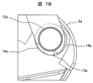
図2は図1の冷蔵室扉2a、2bを保持している上ヒンジ機構部の構成を示す図であり、図3は図2の冷蔵室扉2aの上ヒンジ嵌合部を示す図であり、図4は図2の冷蔵室扉を保持する保持用部材を示す図であり、図5は図2の上ヒンジ機構部の断面を示す図である。
2 is a diagram showing the configuration of the upper hinge mechanism that holds the
以下、冷蔵室扉2aに関して説明するが、逆側の冷蔵室扉2bについても左右対称の同構造を備えており、これについては説明が重複するので省略する。
Hereinafter, the
冷蔵室扉2aは、冷蔵庫1に固定される上ヒンジ12と下ヒンジ(図示せず)によって回転自在に支持される。右側の上ヒンジ12は鋼板で形成されており、これには円筒部12aが一体的に設けられており、円筒部12aはポリアセタール樹脂等の合成樹脂から形成された保持用部材13の中空円筒部13d内に配置される。(この保持用部材13の詳細については図4にて説明する。)つまり、冷蔵室扉2aに設けた上ヒンジ嵌合部14には上ヒンジ円筒部12aと保持用部材13の中空円筒部13dが配置されていることになる。更に、上ヒンジ12に設けた位置決め孔12bには保持用部材13の位置決め突起13eが係合されており、これによって上ヒンジ12と保持用部材13は一体的に回転する構成となっている。
The
そして、本実施例では、冷蔵室扉2aの一方の側に設けたヒンジ嵌合部14と、冷蔵庫1に固定したヒンジ12に設けた保持用部材13を組み合わせ、ヒンジ嵌合部14と保持用部材13の間に、冷蔵室扉2aの所定の開放角度までは冷蔵室扉2aには大きな保持力が作用せず、この所定の開放角度を越えると冷蔵室扉2aには大きな保持力が作用する保持機構を設けるようにした、ところに特徴があるものである。
In this embodiment, the
以下、この保持機構について詳細に説明する。冷蔵室扉2aに設けた、上ヒンジ12の円筒部12a及び保持用部材13の中空円筒部13dが収納される上ヒンジ嵌合部14は、図3、図5に示すように、最も径が小さく真円に形成された上ヒンジ嵌合穴14cと、この上ヒンジ嵌合穴14cよりも上側に段部を有して形成されている変形嵌合穴、ここでは略楕円形に形成された略楕円形ヒンジ嵌合穴14dより構成されている。変形嵌合穴は以下では略楕円形ヒンジ嵌合穴14dとして説明する。
Hereinafter, this holding mechanism will be described in detail. As shown in FIGS. 3 and 5, the diameter of the upper
上ヒンジ嵌合穴14cは上ヒンジ12の円筒部12aを回転自在に軸支するものであり、略楕円形ヒンジ嵌合穴14dは保持用部材13の中空円筒部13dを軸支して冷蔵室扉2aの開放位置の保持を行うものである。この略楕円形ヒンジ嵌合穴14dは上ヒンジ嵌合穴14cよりも径の大きい短形状部、ここでは短径楕円部14aと、最大径の長形状部である長径楕円部14bを基本として複数の円弧を組み合わせて形成されているものである。
The upper hinge
ここで、長形状部と短形状部とで形成される嵌合穴は楕円状でなくても良いものであり、実施例に限定されることなく、要は後述する保持用部材13の中空円筒部13dと協働して摩擦力を発生するような形状を有していれば良いものである。
Here, the fitting hole formed by the long shape portion and the short shape portion does not have to be elliptical, and is not limited to the embodiment, and the essential point is a hollow cylinder of the holding
これによって、短径楕円部14aと長径楕円部14bは一つの略楕円形状の変形嵌合穴を形成している。尚、短径楕円部14a、長径楕円部14b、上ヒンジ嵌合穴14cは同心的に形成されており、破線の円弧は短径楕円部14aの仮想線である。これからわかるように、長径楕円部14bは短径楕円部14aより大きくなっている。
Thereby, the short-
上ヒンジ12に取り付けられる保持用部材13の中空円筒部13dは、図4、図5に示すように、上ヒンジ円筒部12aを収納するように真円に形成された保持部材円筒嵌合部13cを備えている。そして、この保持部材円筒嵌合部13cは所定の肉厚を備えた変形中空筒部とされている。この変形中空筒部は、短形状部である短径円弧状部13aと、この短径円弧状部13aより径の大きい長形状部である長径円弧状部13bより構成される略楕円中空筒部とされている。ここで、長径円弧状部13bは変形可能なように隙間Sが形成されており、この隙間Sによって長径円弧状部13bは縮径するようになっている。
As shown in FIGS. 4 and 5, the hollow
ここで、変形中空筒部の長形状部、短形状部は円弧状でなくても良いものであり、実施例に限定されることなく、要は変形ヒンジ嵌合穴14dと協働して摩擦力を発生するような形状を有いていれば良いものである。
Here, the long shape portion and the short shape portion of the deformed hollow cylinder portion do not have to be arc-shaped, and the present invention is not limited to the embodiment, and the main point is friction in cooperation with the deformed hinge
このように、短径円弧状部13aと長径円弧状部13bは一つの略楕円中空筒部を形成しており、同心的に形成されている。また、上ヒンジ嵌合部14の短径楕円部14aと長径楕円部14b、及び保持用部材13の短径円弧状部13aと長径円弧状部13bは全てが同心円となる。各径の大きさに関しては、14b>13b>14a>13a>12aの外径≒13c≒14cとなる。尚、保持用部材13は上述の通り上ヒンジ12に固定されているので動くことはない。つまり、保持用部材13と上ヒンジ12は一体的に動くものとされている。
Thus, the short-diameter
本実施例においては、上ヒンジ12と冷蔵室扉2aの上ヒンジ嵌合部14、保持用部材13は図5に示すような形態で組み合わされている。保持用部材13の中空円筒部13dには上ヒンジ円筒部12aが嵌合され、この状態で中空円筒部13dは上ヒンジ嵌合部14の略楕円形ヒンジ嵌合穴14dの中に配置される。
In the present embodiment, the
そして、このとき、上ヒンジ円筒部12aは上ヒンジ嵌合穴14cに回動自在に軸支されて冷蔵室扉2aの回転軸となる。また、冷蔵室扉2aの回転とは別に、後述する保持用部材13と上ヒンジ嵌合部14との嵌合の強さ(摩擦抵抗の大きさ)を切り替えることができ、冷蔵室扉2aが開放された時の位置の保持を行うことができる。つまり、上ヒンジ嵌合部14の略楕円形ヒンジ嵌合穴14dと、保持用部材13の中空円筒部13dに形成した長径円弧状部13bの相互作用によって、保持用部材13と上ヒンジ嵌合部14との嵌合の強さによる保持力(=摩擦抵抗の大きさ)を切り替えることができるものである。
At this time, the upper hinge
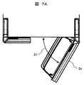
次に、以上のような構成において、その具体的な動作、作用、効果について説明する。図6A、図6Bは冷蔵室扉2aが閉じている状態にある冷蔵庫の上面図及び上ヒンジ機構部の状態を示す図であり、図7は冷蔵室扉2aがある程度開放状態にある冷蔵庫の上面図及び上ヒンジ機構部の状態を示す図であり、図8は冷蔵室扉2aが箱体に対して垂直程度開放された状態にある冷蔵庫の上面図及び上ヒンジ機構部の状態を示す図であり、図9は冷蔵室扉2aが完全に開放された状態にある冷蔵庫の上面図及び上ヒンジ機構部の状態を示す図である。
Next, specific operations, functions, and effects of the above configuration will be described. 6A and 6B are a top view of the refrigerator in a state where the
本実施例の冷蔵室扉2aは、その開放角度によって、冷蔵室扉2aに掛かる保持力(=摩擦抵抗力)が異なるようになっている。この保持力を与える機構は上ヒンジ嵌合部14の略楕円形ヒンジ嵌合穴14dと、保持用部材13の中空円筒部13dに形成した長径円弧状部13bであり、これによって保持用部材13と上ヒンジ嵌合部14との間の保持力(摩擦抵抗の大きさ)を切り替えることができるものである。
The
例えば、図6Aの冷蔵室扉2aが閉じている状態から図7Aの開放角度31の開放された状態までは、上ヒンジ嵌合部14の略楕円形ヒンジ嵌合穴14dの長径楕円部14bと、保持用部材13の中空円筒部13dに形成した長径円弧状部13bとが隙間を介して対向し、開放された冷蔵室扉2aには大きな保持力が作用せず、自由に回動することができる。すなわち、使用者が軽い力で冷蔵室扉2aを自由に開閉できるようになっている。尚、この隙間は略楕円形ヒンジ嵌合穴14dの長径楕円部14bと、保持用部材13の中空円筒部13dに形成した長径円弧状部13bとがほぼ同じ径で、強く接触していない場合も含むものであり、要は、開放された冷蔵室扉2aに大きな保持力が作用せずに、冷蔵室扉2aが軽い力で操作できれば良いものである。
For example, from the state in which the
次に、図7Aに示す開放角度31の状態から図8Aの開放角度32まで開放するにつれ、上ヒンジ嵌合部14の略楕円形ヒンジ嵌合穴14dの短径楕円部14cと、保持用部材13の中空円筒部13dに形成した長径円弧状部13bとが互いに押圧、接触して、この間で両者の摩擦力が徐々に大きくなって摩擦による保持力が増加するようになる。そして開放角度32でその保持力は最大となり、図8Aの開放角度32から図9Aの最大開放角度33まで最大保持力が継続して作用するようになっている。
Next, as it opens from the state of the
更に、上述した動作の詳細を説明する。まず、冷蔵室扉2aが閉じている状態においては、図6(B)に示すように、冷蔵室扉2aが閉じている時の保持用部材13と上ヒンジ嵌合部14の関係は、保持用部材13の長径円弧状部13bが上ヒンジ嵌合部14の長径楕円部14bの範囲内にあり、径の大きさが14b>13bであるため、両者は干渉しないようになっている。
Further, details of the above-described operation will be described. First, when the
つまり、上ヒンジ12を冷蔵庫1に取り付ける際に、冷蔵室扉2aは下ヒンジへ取り付け後に着磁されたガスケット(気密パッキン)にて冷蔵庫1へ仮固定してから上ヒンジ12を取り付ける。上述の構成によって上ヒンジ12を各冷蔵室扉2a、2bの上ヒンジ嵌合部14へ圧入させる必要がなく、保持用部材13が無い状態における組立と変わらず、組立作業性に何ら影響を及ぼさないようになっている。
That is, when the
次に、冷蔵室扉2aが開放角度31だけ開放された状態においては、開放角度31の時の保持用部材13と上ヒンジ嵌合部14の状態は、図7(B)に示すようになっている。
Next, in a state where the
つまり、保持用部材13の中空円筒部13dに形成した長径円弧部13bが上ヒンジ嵌合部14の略楕円形ヒンジ嵌合穴14dの長径楕円部14bと短径楕円部14aの境目にある状態となる。したがって、開放角度31までは、保持用部材13の中空円筒部13dに形成した長径円弧部13bは上ヒンジ嵌合部14の略楕円形ヒンジ嵌合穴14dの短径楕円部14aまでは干渉しないため、冷蔵室扉2aの回転運動には何も影響がない状態となっており、冷蔵室扉2aの開放が重くなるといったことはない。また、冷蔵室扉2a、2bに扉閉をサポートするクローザー等を設けている場合においても、専用の部品を用意するといった必要もないものである。
That is, a state in which the long
扉の開放角度31以下まで冷蔵室扉2aを開放する場合は、冷蔵室2はあまり開放されていない状態であるため、この状態における冷蔵庫の使用目的としては、出し入れしたい食品等をどのスペースより取りだすか、或いは配置するか明確な場合であると考えられ、短時間での開閉が予測される。
When the
例えば、冷蔵室扉2aの内側ポケットに配置した飲料を出し入れする場合である。その場合、冷蔵庫を使用する使用者が開放したい冷蔵室扉2aに手を掛け、掛けた手は離さないで冷蔵室扉2aを支持した状態のまま冷蔵室扉2aを開放し、使用していない手で冷蔵室内の食品等を出し入れした後、そのまま支持していた手で開放した冷蔵室扉2aを閉める動作を行うと想定される。よって、冷蔵室扉2aの開放角度31までは本実施例のようなヒンジ機構による冷蔵室扉2aの保持は必要なく回転運動に影響が無い方が良い。
For example, it is a case where the drink arrange | positioned in the inner side pocket of the
次に、冷蔵室扉2aを図8Aに示す開放角度32まで開放させた場合、図7Aの開放角度31を越えるため、保持用部材13の中空円筒部13dに形成した長径円弧部13bは上ヒンジ嵌合部14の略楕円形ヒンジ嵌合穴14dの短径楕円部14aに干渉するようになる。
Next, when the refrigerating
つまり、この時、長径円弧部13bは中心に向かって変形しようとする。しかしながら、中空円筒部13dの内側には上ヒンジ円筒部12aが配置されているため、長径円弧部13bは隙間Sを無くすように縮径して変形し、最終的には隙間Sは無くなり、これ以上長径円弧部13bは変形しなくなる。よって長径円弧部13bが上ヒンジ円筒部12aと短径楕円部14aの間に挟まれ、これよって摩擦力が発生する。この摩擦力により冷蔵室扉2aは回転運動するも、その摺動形態が重くなって抵抗力となり、結果的に開放した冷蔵室扉2aをその位置に保持する力となる。
That is, at this time, the
冷蔵室扉2aの開放角度31より開放角度が大きくなるにつれ、摩擦力も大きくなり、開放角度32まで達した時、図8(B)に示すように、長径円弧部13bは短径楕円部14aの範囲に位置して摩擦力は最大となる。つまり、開放角度32の状態で、冷蔵室扉2aの保持力は最大となる。そして、冷蔵室扉2aの最大となった保持力は、開放角度32より図9A、図9Bにある最大開放角度33まで適用されるようになる。
As the opening angle becomes larger than the opening
冷蔵室扉2aを開放角度32から最大開放角度33の状態まで開放した冷蔵庫の使用目的は、冷蔵室扉2aを大きくあけることから、大きいサイズの食品等の出し入れや、小さくても複数の食品等の出し入れがあると想定される。また、冷蔵室の冷蔵室扉2aが本実施例のように観音開きの場合は、両方の冷蔵室扉2a、2bを同じだけ開放する可能性が高い。この状態での使用状況は、開放させた冷蔵室扉2a、2bより手を離し、両手を使用しての食品等の出し入れや、冷蔵室内の整理等を行うことが考えられる。この状況において、開放された冷蔵室扉2a、2bが意図せず動くことは、使用者にとって不快感や不便感を与えてしまう。したがって、本状態において開放した冷蔵室扉2a、2bの保持は必要であるため、最大の保持力が掛かるようにしている。
The purpose of using the refrigerator in which the
以上のように、使用目的によって変化する冷蔵室扉2aの開放角度に合わせて、冷蔵室扉2aに掛かる保持力を変化させている。しかし、冷蔵室扉2aが閉じた状態から最大保持力が働く開放角度32以上まで冷蔵室扉2aを開放させたときに、変化する保持力の差が大きいと、扉の開閉動作に違和感を覚えてしまうことがある。そのため、その差を小さくする、また開放角度31から開放角度32までの開放角度の間で摩擦力を徐々に変化させるようにすることで、違和感を覚えないよう配慮することができる。このためには、本実施例では略楕円形ヒンジ嵌合穴14dの短径楕円部14aは同一の径となっているが、徐々にその径を小さくするようにして、摩擦力が次第に増大するようにしても良いものである。
As described above, the holding force applied to the
本実施例では冷蔵室扉が観音開きのタイプで説明したが、片開きの1枚扉の場合であっても、冷蔵室扉に限らず冷凍室扉や野菜室扉等であっても、ヒンジを用いた回転式扉であれば何れにも適用できるものである。また、保持用部材を配置する場所も、上ヒンジではなく下ヒンジ、或いは両方のヒンジに配置しても同等の効果が得ることができるものである。 In this embodiment, the refrigerating room door has been described as a double door type, but even in the case of a single door with a single opening, the hinge is not limited to a refrigerating room door or a freezer room door or a vegetable room door. Any rotary door can be used. Further, even when the holding member is arranged on the lower hinge instead of the upper hinge, or on both hinges, the same effect can be obtained.
更に、電動式の扉開放機構(図示せず)を用いて冷蔵室扉2a、2bを開放する場合についても同等の効果を得ることができる。例えば、冷蔵庫の天井部に扉開放機構(図示なし)を設け、冷蔵室扉2aの前面に備えられた操作部を操作することで、扉開放機構から押出し部材が突出して冷蔵室扉2aが開放されるようにすることができる。このとき、この押出し部材により開放方向に押されドアパッキンから引き剥がされ加速した冷蔵室扉2aは、摩擦力の小さい開放角度31の位置で徐々に減速するが停止はせず、摩擦力が最大である開放角度32の位置に到達して停止するようにすることができる。
Furthermore, the same effect can be obtained when the
即ち、開放角度31時点における、扉開放機構で開放された冷蔵室扉2aの開き力と上ヒンジ12に生じる摩擦力との関係を『開き力>摩擦力』とし、また、開放角度32時点における関係を『開き力<摩擦力』とし、扉開放機構で開放された冷蔵室扉2aが開放角度32(即ち約90度)で停止するように、冷蔵室扉2aに掛かる保持力(摩擦力)を徐々に変化させることができる。
That is, the relationship between the opening force of the
上述のように、開放角度32の位置で停止するよう冷蔵室扉2aに掛かる保持力を変化させることで、冷蔵庫の側面を壁際に設置したときに、扉開放機構によって勢いよく開放された冷蔵庫扉が壁に衝突することを防ぐことができる。
As described above, by changing the holding force applied to the
また、近年、扉の前面化粧板を鋼板ではなく強化ガラスにすることで高級感をまして意匠性を向上した冷蔵庫の需要が高まっている。上述したような設置条件において、扉開放機構により冷蔵室扉が勢いよく開放したときに、冷蔵室扉前面の強化ガラス部材が壁に衝突することを防ぐため、開放角度32の位置で停止するよう冷蔵室扉2aに掛かる保持力を徐々に変化させて、これを防止することができる。また、冷蔵室扉を停止させる位置は、庫内の見易さ、食品の収納及び取り出し易さ、上述の壁際への設置都合等を考慮すると、開放角度32の位置が望ましいものである。
In recent years, there has been an increasing demand for refrigerators that have a high-class feeling and improved design by making the front decorative plate of the door not a steel plate but a tempered glass. Under the installation conditions as described above, when the door of the refrigerator compartment is opened vigorously by the door opening mechanism, the tempered glass member on the front side of the refrigerator compartment door is prevented from colliding with the wall so as to stop at the
更に、貯蔵室の扉が観音開き式や片開き式、或いは異なる大きさの扉、或いは冷凍室、野菜室等の別の貯蔵室の扉であっても、ヒンジを使用した回転式扉であれば、各扉に設けたヒンジ嵌合穴の形状を変更することにより、同じ保持用部材を使用できて同等の効果を得ることができる。 Furthermore, even if the door of the storage room is a double door type, a single door type, a door of a different size, or a door of another storage room such as a freezer room, a vegetable room, etc. By changing the shape of the hinge fitting hole provided in each door, the same holding member can be used and the same effect can be obtained.
以上述べた通り、本発明によれば、回転式扉に設けたヒンジ嵌合部とヒンジに設けた保持用部材を組み合わせ、ヒンジ嵌合部と保持用部材の間に、回転式扉の所定の開放角度までは回転式扉には大きな保持力が作用せず、この所定の開放角度を越えると回転式扉には大きな保持力が作用する保持機構を設けるようにしたので、回転式扉は所定の開放角度で保持された状態を保つことができ、使い勝手が向上するようになるものである。 As described above, according to the present invention, the hinge fitting part provided on the rotary door and the holding member provided on the hinge are combined, and the predetermined part of the rotary door is provided between the hinge fitting part and the holding member. Until the opening angle, a large holding force does not act on the rotary door, and when the predetermined opening angle is exceeded, the rotary door is provided with a holding mechanism that applies a large holding force. It is possible to maintain the state held at the opening angle, and the usability is improved.
1…冷蔵庫本体、2…冷蔵室、2a…右側冷蔵室扉、2b…左側冷蔵室扉、3……製氷室、3a…製氷室扉、4……上段冷凍室、4a…上段冷凍室扉、5……下段冷凍室、5a…下段冷凍室扉、6……野菜室、6a…野菜室扉、11a…右側ヒンジカバー、11b…左側ヒンジカバー、12…右側上ヒンジ、12a…上ヒンジ円筒部、13…保持部材、13a…短径円弧部、13b…長径円弧部、13c…保持部材円筒嵌合部、14…上ヒンジ嵌合部、14a…短径楕円部、14b…長径楕円部、14c…上ヒンジ円筒嵌合部、31…開放角度、32…開放角度、33…開放最大角度。 DESCRIPTION OF SYMBOLS 1 ... Refrigerator main body, 2 ... Refrigeration room, 2a ... Right refrigeration room door, 2b ... Left refrigeration room door, 3 ... Ice making room, 3a ... Ice making room door, 4 ... Upper stage freezer room, 4a ... Upper stage freezer room door, 5 ... Lower freezer compartment, 5a ... Lower freezer compartment door, 6 ... Vegetable compartment, 6a ... Vegetable compartment door, 11a ... Right hinge cover, 11b ... Left hinge cover, 12 ... Right upper hinge, 12a ... Upper hinge cylindrical part , 13 ... holding member, 13a ... short diameter arc part, 13b ... long diameter arc part, 13c ... holding member cylindrical fitting part, 14 ... upper hinge fitting part, 14a ... short diameter ellipse part, 14b ... long diameter ellipse part, 14c ... upper hinge cylindrical fitting part, 31 ... opening angle, 32 ... opening angle, 33 ... opening maximum angle.
Claims (3)
前記回転式扉に設けたヒンジ嵌合穴に前記ヒンジに設けた合成樹脂からなる保持用部材を収納して組み合わせ、前記ヒンジ嵌合穴と前記保持用部材の間に、前記回転式扉の所定の開放角度までは前記回転式扉に大きな保持力が作用せず、前記所定の開放角度を越えると前記回転式扉に大きな保持力が作用する保持機構を設け、
前記保持機構は、前記ヒンジ嵌合穴を形成する変形嵌合穴及び前記変形嵌合穴より小径で円形の上ヒンジ嵌合穴と、前記保持用部材に形成され前記変形嵌合穴に収納される変形中空筒部とより構成され、前記変形中空筒部には前記ヒンジが配置され、更に、前記変形中空筒部より突き出た前記ヒンジは前記上ヒンジ嵌合穴に回転自在に軸支されると共に、
前記変形嵌合穴は、長形状部と短形状部を有する変形嵌合穴であり、前記変形中空筒部は、前記変形嵌合穴の前記長形状部より短く前記短形状部より長い長形状部を有し、しかも前記長形状部は変形可能なように隙間が形成されている変形中空筒部であり、前記回転式扉が全閉から前記所定の開放角度に達する前までは前記変形嵌合穴の前記長形状部と前記変形中空筒部の前記長形状部とが隙間を介して対向し、前記回転式扉が前記所定の開放角度を越えると前記変形嵌合穴の前記短形状部と前記変形中空筒部の前記長形状部とが接触して摩擦を生じて前記回転式扉の保持力を与えることを特徴とする冷蔵庫。 In a refrigerator that includes a storage room, a rotary door that opens and closes a front opening of the storage room, and a hinge that supports the rotary door, the rotary door being opened and closed with the hinge as a rotation axis.
A holding member made of a synthetic resin provided on the hinge is accommodated and combined in a hinge fitting hole provided in the rotary door, and a predetermined part of the rotary door is provided between the hinge fitting hole and the holding member. Until the opening angle, a holding mechanism that does not act on the rotary door and a large holding force acts on the rotary door when the predetermined opening angle is exceeded,
The holding mechanism is formed in the deformation fitting hole that forms the hinge fitting hole, the upper hinge fitting hole that is smaller in diameter than the deformation fitting hole and circular, and is formed in the holding member, and is accommodated in the deformation fitting hole. And the hinge is disposed in the deformed hollow tube portion, and the hinge protruding from the deformed hollow tube portion is rotatably supported in the upper hinge fitting hole. With
The deformation fitting hole is a deformation fitting hole having a long shape portion and a short shape portion, and the deformation hollow cylinder portion is shorter than the long shape portion of the deformation fitting hole and longer than the short shape portion. And the long shape portion is a deformed hollow cylindrical portion in which a gap is formed so as to be deformable, and the deformable fitting is performed until the rotary door reaches the predetermined opening angle from the fully closed position. When the long shape portion of the fitting hole and the long shape portion of the deformed hollow cylinder portion face each other through a gap, and the rotary door exceeds the predetermined opening angle, the short shape portion of the deformation fitting hole And the long-shaped portion of the deformed hollow cylinder portion are brought into contact with each other to generate friction to provide a holding force for the rotary door .
前記回転式扉に設けたヒンジ嵌合穴に前記ヒンジに設けた合成樹脂からなる保持用部材を収納して組み合わせ、前記ヒンジ嵌合穴と前記保持用部材の間に、前記回転式扉の所定の開放角度までは前記回転式扉に大きな保持力が作用せず、前記所定の開放角度を越えると前記回転式扉に大きな保持力が作用する保持機構を設け、A holding member made of a synthetic resin provided on the hinge is accommodated and combined in a hinge fitting hole provided in the rotary door, and a predetermined part of the rotary door is provided between the hinge fitting hole and the holding member. Until the opening angle, a holding mechanism that does not act on the rotary door and a large holding force acts on the rotary door when the predetermined opening angle is exceeded,
前記保持機構は、前記ヒンジ嵌合穴を形成する変形嵌合穴及び前記変形嵌合穴より小径で円形の上ヒンジ嵌合穴と、前記保持用部材に形成され前記変形嵌合穴に収納される変形中空筒部とより構成され、前記変形中空筒部には前記ヒンジが配置され、更に、前記変形中空筒部より突き出た前記ヒンジは前記上ヒンジ嵌合穴に回転自在に軸支されると共に、 The holding mechanism is formed in the deformation fitting hole that forms the hinge fitting hole, the upper hinge fitting hole that is smaller in diameter than the deformation fitting hole and circular, and is formed in the holding member, and is accommodated in the deformation fitting hole. And the hinge is disposed in the deformed hollow tube portion, and the hinge protruding from the deformed hollow tube portion is rotatably supported in the upper hinge fitting hole. With
前記変形嵌合穴は長径部と短径部を有する略楕円形の略楕円形嵌合穴であり、前記変形中空筒部は長径円弧部と短径円弧部を有し、しかも前記長径円弧部は変形可能なように隙間が形成されている略楕円中空筒部であり、前記略楕円中空筒部の前記長径円弧部は前記略楕円形嵌合穴の前記長径より短く前記短径より長く形成されており、前記回転式扉が全閉から前記所定の開放角度に達する前までは前記略楕円形嵌合穴の前記長径部と前記略楕円中空筒部の前記長径円弧部とが隙間を介して対向し、前記回転式扉が前記所定の開放角度を越えると前記略楕円形嵌合穴の前記短径部と前記略楕円中空筒部の前記長径円弧部とが接触して摩擦を生じて前記回転式扉の保持力を与えることを特徴とする冷蔵庫。The deformation fitting hole is a substantially elliptical substantially elliptical fitting hole having a long diameter portion and a short diameter portion, and the deformation hollow cylinder portion has a long diameter arc portion and a short diameter arc portion, and the long diameter arc portion. Is a substantially oval hollow cylinder part in which a gap is formed so as to be deformable, and the major-arc arc part of the substantially oval hollow cylinder part is shorter than the major axis of the substantially elliptical fitting hole and longer than the minor axis. Until the rotary door reaches the predetermined opening angle from the fully closed position, the major diameter portion of the substantially elliptical fitting hole and the major diameter arc portion of the substantially elliptical hollow cylindrical portion are interposed via a gap. When the rotary door exceeds the predetermined opening angle, the short diameter part of the substantially elliptical fitting hole and the long diameter arc part of the substantially elliptical hollow cylindrical part come into contact with each other to generate friction. A refrigerator that provides holding force for the rotary door.
前記冷蔵庫は複数の回転式扉を有し、これらの回転式扉には前記ヒンジ嵌合穴と前記保持用部材及び前記保持機構を備えており、更に夫々の前記各回転式扉の前記ヒンジ嵌合穴は異なる形状であることを特徴とする冷蔵庫。The refrigerator has a plurality of rotary doors, and the rotary doors are provided with the hinge fitting holes, the holding members, and the holding mechanism, and the hinge fittings of the respective rotary doors. The refrigerator is characterized in that the joint holes have different shapes.
Priority Applications (1)
| Application Number | Priority Date | Filing Date | Title |
|---|---|---|---|
| JP2013181315A JP6051127B2 (en) | 2013-09-02 | 2013-09-02 | refrigerator |
Applications Claiming Priority (1)
| Application Number | Priority Date | Filing Date | Title |
|---|---|---|---|
| JP2013181315A JP6051127B2 (en) | 2013-09-02 | 2013-09-02 | refrigerator |
Publications (3)
| Publication Number | Publication Date |
|---|---|
| JP2015048991A JP2015048991A (en) | 2015-03-16 |
| JP2015048991A5 JP2015048991A5 (en) | 2015-11-05 |
| JP6051127B2 true JP6051127B2 (en) | 2016-12-27 |
Family
ID=52699165
Family Applications (1)
| Application Number | Title | Priority Date | Filing Date |
|---|---|---|---|
| JP2013181315A Active JP6051127B2 (en) | 2013-09-02 | 2013-09-02 | refrigerator |
Country Status (1)
| Country | Link |
|---|---|
| JP (1) | JP6051127B2 (en) |
Families Citing this family (3)
| Publication number | Priority date | Publication date | Assignee | Title |
|---|---|---|---|---|
| KR20140132522A (en) * | 2013-05-08 | 2014-11-18 | 삼성전자주식회사 | Refrigerator |
| JP6792349B2 (en) * | 2016-05-27 | 2020-11-25 | 東芝ライフスタイル株式会社 | refrigerator |
| JP7036877B2 (en) * | 2020-09-16 | 2022-03-15 | 東芝ライフスタイル株式会社 | refrigerator |
Family Cites Families (12)
| Publication number | Priority date | Publication date | Assignee | Title |
|---|---|---|---|---|
| JPS5079053U (en) * | 1973-11-19 | 1975-07-08 | ||
| DE7616362U1 (en) * | 1976-05-21 | 1976-09-30 | Stapper, Johann, 5023 Weiden | FURNITURE HINGE WITH BRAKE |
| JPS5363652A (en) * | 1976-11-17 | 1978-06-07 | Hitachi Ltd | Door closing device for refrigerator |
| JPH0245269U (en) * | 1988-09-20 | 1990-03-28 | ||
| CZ331796A3 (en) * | 1996-01-03 | 1997-07-16 | Scharwaechter Gmbh Co Kg | Door hinge of motor vehicle with braking and holding-down functions |
| DE19726536A1 (en) * | 1997-06-23 | 1998-12-24 | Daimler Benz Ag | Hinge for the pivotable mounting of a component |
| JP2000123237A (en) * | 1998-10-20 | 2000-04-28 | Sanden Corp | Door holding device of automatic vending machine |
| DE10222898A1 (en) * | 2001-06-11 | 2002-12-19 | Klingelhoefer Jost | Door hinge for vehicle door has integrated brake and comprises separate bush lining bore in hinge eye and having stepped decreasing diameter |
| JP2004301457A (en) * | 2003-03-31 | 2004-10-28 | Toshiba Corp | Refrigerator and hinge mechanism for the same |
| JP2008134002A (en) * | 2006-11-28 | 2008-06-12 | Hitachi Appliances Inc | Refrigerator |
| JP5169706B2 (en) * | 2008-10-08 | 2013-03-27 | パナソニック株式会社 | refrigerator |
| JP2010127477A (en) * | 2008-11-25 | 2010-06-10 | Sharp Corp | Refrigerator |
-
2013
- 2013-09-02 JP JP2013181315A patent/JP6051127B2/en active Active
Also Published As
| Publication number | Publication date |
|---|---|
| JP2015048991A (en) | 2015-03-16 |
Similar Documents
| Publication | Publication Date | Title |
|---|---|---|
| EP4006465A1 (en) | Refrigerator | |
| US7712186B2 (en) | Hinge device for refrigerator | |
| US8944534B2 (en) | Refrigerator includes a second door disposed on a first door, a shelf disposed on the first door, a connection assembly connecting the shelf to the second door and linking opening of the second door to rotate the shelf | |
| JPWO2006006707A1 (en) | Door device and refrigerator | |
| US20070262686A1 (en) | Refrigerator | |
| EP3034973B1 (en) | Refrigerator | |
| KR102245371B1 (en) | Fixing device and refrigerator having the same | |
| JP6051127B2 (en) | refrigerator | |
| US9845628B2 (en) | Refrigerator | |
| US11892228B2 (en) | Appliance bin | |
| KR20140104640A (en) | Refrigerator having double doors | |
| EP4006286A1 (en) | Refrigerator | |
| EP2857779B1 (en) | Turnover beam and refrigerator provided with same | |
| JP2011106696A (en) | Refrigerator | |
| EP4006283A1 (en) | Refrigerator | |
| JP2009228994A (en) | Refrigerator | |
| JP2019138537A (en) | refrigerator | |
| JP2006057904A (en) | Refrigerator | |
| EP3483539B1 (en) | Bin assembly | |
| JP2014142146A (en) | Refrigerator | |
| JP2016031222A (en) | Cold storage | |
| US20110179819A1 (en) | Refrigerator | |
| JP2014037922A (en) | Shelf structure for refrigerator | |
| JP2020176741A (en) | Door stopper and refrigerator | |
| WO2017002343A1 (en) | Refrigerator |
Legal Events
| Date | Code | Title | Description |
|---|---|---|---|
| A521 | Written amendment |
Free format text: JAPANESE INTERMEDIATE CODE: A523 Effective date: 20150910 |
|
| A621 | Written request for application examination |
Free format text: JAPANESE INTERMEDIATE CODE: A621 Effective date: 20150910 |
|
| A977 | Report on retrieval |
Free format text: JAPANESE INTERMEDIATE CODE: A971007 Effective date: 20160609 |
|
| A131 | Notification of reasons for refusal |
Free format text: JAPANESE INTERMEDIATE CODE: A131 Effective date: 20160614 |
|
| A521 | Written amendment |
Free format text: JAPANESE INTERMEDIATE CODE: A523 Effective date: 20160808 |
|
| TRDD | Decision of grant or rejection written | ||
| A01 | Written decision to grant a patent or to grant a registration (utility model) |
Free format text: JAPANESE INTERMEDIATE CODE: A01 Effective date: 20161101 |
|
| A61 | First payment of annual fees (during grant procedure) |
Free format text: JAPANESE INTERMEDIATE CODE: A61 Effective date: 20161128 |
|
| R150 | Certificate of patent or registration of utility model |
Ref document number: 6051127 Country of ref document: JP Free format text: JAPANESE INTERMEDIATE CODE: R150 |
|
| S533 | Written request for registration of change of name |
Free format text: JAPANESE INTERMEDIATE CODE: R313533 |
|
| R350 | Written notification of registration of transfer |
Free format text: JAPANESE INTERMEDIATE CODE: R350 |