EP2857779B1 - Turnover beam and refrigerator provided with same - Google Patents
Turnover beam and refrigerator provided with same Download PDFInfo
- Publication number
- EP2857779B1 EP2857779B1 EP13884952.6A EP13884952A EP2857779B1 EP 2857779 B1 EP2857779 B1 EP 2857779B1 EP 13884952 A EP13884952 A EP 13884952A EP 2857779 B1 EP2857779 B1 EP 2857779B1
- Authority
- EP
- European Patent Office
- Prior art keywords
- door
- elastic structure
- refrigerator
- cover plate
- mount
- Prior art date
- Legal status (The legal status is an assumption and is not a legal conclusion. Google has not performed a legal analysis and makes no representation as to the accuracy of the status listed.)
- Not-in-force
Links
Images


Classifications
-
- F—MECHANICAL ENGINEERING; LIGHTING; HEATING; WEAPONS; BLASTING
- F25—REFRIGERATION OR COOLING; COMBINED HEATING AND REFRIGERATION SYSTEMS; HEAT PUMP SYSTEMS; MANUFACTURE OR STORAGE OF ICE; LIQUEFACTION SOLIDIFICATION OF GASES
- F25D—REFRIGERATORS; COLD ROOMS; ICE-BOXES; COOLING OR FREEZING APPARATUS NOT OTHERWISE PROVIDED FOR
- F25D23/00—General constructional features
- F25D23/02—Doors; Covers
-
- F—MECHANICAL ENGINEERING; LIGHTING; HEATING; WEAPONS; BLASTING
- F25—REFRIGERATION OR COOLING; COMBINED HEATING AND REFRIGERATION SYSTEMS; HEAT PUMP SYSTEMS; MANUFACTURE OR STORAGE OF ICE; LIQUEFACTION SOLIDIFICATION OF GASES
- F25D—REFRIGERATORS; COLD ROOMS; ICE-BOXES; COOLING OR FREEZING APPARATUS NOT OTHERWISE PROVIDED FOR
- F25D2323/00—General constructional features not provided for in other groups of this subclass
- F25D2323/02—Details of doors or covers not otherwise covered
- F25D2323/021—French doors
Definitions
- the present invention relates to the technical fields of refrigerators, wine cabinets, beverage containers and freezers, and in particular, to a turnover beam for use in a refrigerator door and a refrigerator provided with the turnover beam, which is generally used the door a side-by-side door-equipped refrigerated compartment, a French refrigerator, and multi-door refrigerator, and a cross-like four-door refrigerator.
- a turnover beam capable of turning over at 90 degrees is designed on a refrigerator door on one side of the refrigerator. It is generally required that when the door is closed, the turnover beam is parallel to the door, and when the door is opened, the turnover beam is perpendicular to the door. It is a common practice that a torsion spring is used to ensure that the turnover beam is only maintained stable at either of the two positions, that is, a door open position or a door close position.
- the torsion spring is typically provided outside the turnover beam, thereby affecting appearance of the refrigerator.
- service life of the torsion spring is limited, and opening and closing during long-term use of the refrigerator may cause damages to the torsion spring, which resulting in failure of the turnover beam.
- the torsion spring is definitely subjected to a dead center. In this case, if the design is not proper, the turnover beam may remain at the dead center, affecting normal use of the refrigerator.
- Document JP H04 225774 A relates to a known door device for a refrigerator.
- document WO 2009/109878 A1 a known household refrigerating appliance is described.
- the technical problem to be solved in the present invention is to provide a turnover beam featuring simple structure, convenient mounting and long service life, and a refrigerator provided with the turnover beam.
- a turnover beam comprising: a front cover plate, a rear cover plate, a mount, and an elastic structure; wherein: the front cover plate and the rear cover plate mate with each other to form a cavity, the mount and the elastic structure being positioned in the cavity; the mount comprises a fixing position coupled to a refrigerator door and a rotating shaft hinged to a hole provided on the front cover plate, the rotating shaft being provided with a limiting stopper; and one end of the elastic structure is fixed into the cavity, and the other end of the elastic structure is a free end which elastically contacts with the limiting stopper, when the refrigerator door is at either of two limiting positions, the free end of the elastic structure being positioned on two sides of the limiting stopper, and when the refrigerator door is between the two limiting positions, the free end of the elastic structure being in elastic contact with the limiting stopper.
- the mount and the elastic structure are positioned inside the cavity, which causes no impact on the appearance and facilitates the mounting.
- the conventional torsion spring is replaced by contacting the elastic structure and the limiting stopper, and open and close states thereof are shifted by means of deformation and resilience of the elastic structure. Therefore, no "dead center” is caused and the service life is prolonged.
- the elastic structure is an elastic piece
- the limiting stopper of the mount is of an arch structure
- one end of the elastic structure is fixed onto the front cover plate
- the two limiting positions are a door close position and a door open position.
- the present invention further provides a refrigerator, comprising: a cabinet, the cabinet being provided with at least one compartment, the compartment being provided with side-by-side doors; and at least one group of the above-mentioned turnover beams, the turnover beams being mounted on side surfaces of the doors.
- the turnover beam is in parallel with the door when the door is closed, and the turnover beam is perpendicular to the door when the door is opened.
- the mount and the elastic structure are positioned inside the cavity, which causes no impact on the appearance and facilitates the mounting.
- the conventional torsion spring is replaced by contacting of the elastic structure and the limiting stopper, and open and close states thereof are shifted by means of deformation and resilience of the elastic structure. Therefore, no "dead center” is caused and the service life is prolonged.
- an embodiment of the present invention provides a turnover beam, comprising: a front cover plate 1, a rear cover plate 2, a mount 3, and an elastic structure 4.
- the front cover plate 1 and the rear cover plate 2 mate with each other to form a cavity, wherein the mount 3 and the elastic structure 4 are positioned in the cavity.
- the mount 3 comprises a fixing position 32 coupled to a refrigerator door and a rotating shaft 31 hinged to a hole 11 provided on the front cover plate 1, wherein the rotating shaft 31 is provided with a limiting stopper 33.
- One end of the elastic structure 4 is fixed into the cavity, and the other end of the elastic structure 4 is a free end which elastically contacts with the limiting stopper 33, wherein when the refrigerator door is at either of two limiting positions, the free end of the elastic structure 4 is positioned on two sides of the limiting stopper 33, and when the refrigerator door is between the two limiting positions, the free end of the elastic structure 4 is in elastic contact with the limiting stopper 33.
- the front cover plate 1 is fixed to the rear cover plate 2 via snap-fitting.
- a foam, a heating wire and the like are also defined in the above cavity.
- the mount 3 is fixed onto a container rib on a lateral side of the door.
- the elastic structure 4 is an elastic piece
- the limiting stopper 33 of the mount 3 is of an arch structure
- one end of the elastic structure 4 is fixed onto the front cover plate 1, and the two limiting positions are a door close position and a door open position.
- one end of the elastic piece is fixed onto the front cover plate via a screw 5, the free end is arc-shaped, an outer side of the mount is also provided with an section of arc-shaped structure, and when the door is closed, the elastic piece is in contact with one side of the limiting stopper of the mount to ensure that the turnover beam is stably in this state.
- the elastic piece is subjected to deformation due to extrusion, and when turnover of the turnover beam exceeds a specific angle, a resilience force of the elastic piece causes the turnover beam to continuously turn over until the door is opened.
- the elastic piece is in contact with the other side of the limiting stopper of the mount to ensure that the turnover beam is stably in this state.
- the present invention further provides a refrigerator, comprising: a cabinet, the cabinet being provided with at least one compartment, the compartment being provided with side-by-side doors; and at least one group of the above-mentioned turnover beams, the turnover beams being mounted on side surfaces of the doors.
- the turnover beam is in parallel with the door when the door is closed, and the turnover beam is perpendicular to the door when the door is opened.
Description
- The present invention relates to the technical fields of refrigerators, wine cabinets, beverage containers and freezers, and in particular, to a turnover beam for use in a refrigerator door and a refrigerator provided with the turnover beam, which is generally used the door a side-by-side door-equipped refrigerated compartment, a French refrigerator, and multi-door refrigerator, and a cross-like four-door refrigerator.
- At present, conventional refrigerated compartments in the market are generally configured in refrigerators equipped with side-by-side doors, such as French refrigerators, multi-door refrigerators and the like. Typically a turnover beam capable of turning over at 90 degrees is designed on a refrigerator door on one side of the refrigerator. It is generally required that when the door is closed, the turnover beam is parallel to the door, and when the door is opened, the turnover beam is perpendicular to the door. It is a common practice that a torsion spring is used to ensure that the turnover beam is only maintained stable at either of the two positions, that is, a door open position or a door close position.
- In the above design, the torsion spring is typically provided outside the turnover beam, thereby affecting appearance of the refrigerator. In addition, service life of the torsion spring is limited, and opening and closing during long-term use of the refrigerator may cause damages to the torsion spring, which resulting in failure of the turnover beam. During shift of the torsion spring between the two states, the torsion spring is definitely subjected to a dead center. In this case, if the design is not proper, the turnover beam may remain at the dead center, affecting normal use of the refrigerator.
- Document
JP H04 225774 A WO 2009/109878 A1 a known household refrigerating appliance is described. - The technical problem to be solved in the present invention is to provide a turnover beam featuring simple structure, convenient mounting and long service life, and a refrigerator provided with the turnover beam.
- To solve the above technical problem, the present invention employs the following technical solution: a turnover beam, comprising: a front cover plate, a rear cover plate, a mount, and an elastic structure; wherein: the front cover plate and the rear cover plate mate with each other to form a cavity, the mount and the elastic structure being positioned in the cavity; the mount comprises a fixing position coupled to a refrigerator door and a rotating shaft hinged to a hole provided on the front cover plate, the rotating shaft being provided with a limiting stopper; and one end of the elastic structure is fixed into the cavity, and the other end of the elastic structure is a free end which elastically contacts with the limiting stopper, when the refrigerator door is at either of two limiting positions, the free end of the elastic structure being positioned on two sides of the limiting stopper, and when the refrigerator door is between the two limiting positions, the free end of the elastic structure being in elastic contact with the limiting stopper.
- According to the present invention, the mount and the elastic structure are positioned inside the cavity, which causes no impact on the appearance and facilitates the mounting. In addition, the conventional torsion spring is replaced by contacting the elastic structure and the limiting stopper, and open and close states thereof are shifted by means of deformation and resilience of the elastic structure. Therefore, no "dead center" is caused and the service life is prolonged.
- Specifically, the elastic structure is an elastic piece, the limiting stopper of the mount is of an arch structure, one end of the elastic structure is fixed onto the front cover plate, and the two limiting positions are a door close position and a door open position.
- In addition, the present invention further provides a refrigerator, comprising: a cabinet, the cabinet being provided with at least one compartment, the compartment being provided with side-by-side doors; and at least one group of the above-mentioned turnover beams, the turnover beams being mounted on side surfaces of the doors.
- The turnover beam is in parallel with the door when the door is closed, and the turnover beam is perpendicular to the door when the door is opened.
- Compared with the prior art, the beneficial effects of the present disclosure lie in that:
- According to the present invention, the mount and the elastic structure are positioned inside the cavity, which causes no impact on the appearance and facilitates the mounting. In addition, the conventional torsion spring is replaced by contacting of the elastic structure and the limiting stopper, and open and close states thereof are shifted by means of deformation and resilience of the elastic structure. Therefore, no "dead center" is caused and the service life is prolonged.
-
-
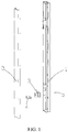
FIG. 1 is an exploded schematic structural view of a turnover beam according to the present invention; -
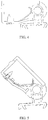
FIG. 2 is a schematic structural view of a mount according to the present invention; -
FIG. 3 is a schematic structural view of a combination of the mount and a front cover plate according to the present invention; and -
FIGS. 4 to 6 are schematic structural views of the turnover beam from a door close state to a door open state according to the present invention. - The present invention is further described with reference to a specific embodiment.
- As illustrated in
FIG. 1 ,FIG. 2, and FIG. 3 , an embodiment of the present invention provides a turnover beam, comprising: afront cover plate 1, a rear cover plate 2, amount 3, and anelastic structure 4. Thefront cover plate 1 and the rear cover plate 2 mate with each other to form a cavity, wherein themount 3 and theelastic structure 4 are positioned in the cavity. Themount 3 comprises afixing position 32 coupled to a refrigerator door and a rotatingshaft 31 hinged to a hole 11 provided on thefront cover plate 1, wherein the rotatingshaft 31 is provided with alimiting stopper 33. One end of theelastic structure 4 is fixed into the cavity, and the other end of theelastic structure 4 is a free end which elastically contacts with thelimiting stopper 33, wherein when the refrigerator door is at either of two limiting positions, the free end of theelastic structure 4 is positioned on two sides of thelimiting stopper 33, and when the refrigerator door is between the two limiting positions, the free end of theelastic structure 4 is in elastic contact with thelimiting stopper 33. - The
front cover plate 1 is fixed to the rear cover plate 2 via snap-fitting. In addition, a foam, a heating wire and the like are also defined in the above cavity. Themount 3 is fixed onto a container rib on a lateral side of the door. - Specifically, the
elastic structure 4 is an elastic piece, thelimiting stopper 33 of themount 3 is of an arch structure, one end of theelastic structure 4 is fixed onto thefront cover plate 1, and the two limiting positions are a door close position and a door open position. - As illustrated in
FIG. 4 to FIG. 6 , one end of the elastic piece is fixed onto the front cover plate via ascrew 5, the free end is arc-shaped, an outer side of the mount is also provided with an section of arc-shaped structure, and when the door is closed, the elastic piece is in contact with one side of the limiting stopper of the mount to ensure that the turnover beam is stably in this state. When the door is being opened, the elastic piece is subjected to deformation due to extrusion, and when turnover of the turnover beam exceeds a specific angle, a resilience force of the elastic piece causes the turnover beam to continuously turn over until the door is opened. In the door open state, the elastic piece is in contact with the other side of the limiting stopper of the mount to ensure that the turnover beam is stably in this state. - In addition, the present invention further provides a refrigerator, comprising: a cabinet, the cabinet being provided with at least one compartment, the compartment being provided with side-by-side doors; and at least one group of the above-mentioned turnover beams, the turnover beams being mounted on side surfaces of the doors.
- The turnover beam is in parallel with the door when the door is closed, and the turnover beam is perpendicular to the door when the door is opened.
- Obviously, the above embodiment is merely an exemplary one for illustrating the present invention, but is not intended to limit the implementation of the present invention. Persons of ordinary skills in the art may derive other modifications and variations based on the above embodiment. All embodiments of the present invention are not exhaustively listed herein. Any modification, equivalent replacement, or improvement made without departing from the principle of the present invention should fall within the protection scope of the present invention.
Claims (6)
- A refrigerator, comprising:a cabinet, the cabinet being provided with at least one compartment, the compartment being provided with side-by-side doors; andat least one group of turnover beams mounted on side surfaces of the doors; a turnover beam comprising: a front cover plate (1), a rear cover plate (2), a mount (3), and an elastic structure (4); and in that: the front cover plate (1) and the rear cover plate (2) mate with each other to form a cavity, the mount (3) and the elastic structure (4) are being positioned in the cavity; the mount (3) comprises a fixing position (32) coupled to a refrigerator door and a rotating shaft (31) hinged to a hole (11) provided on the front cover plate (1), characterized in that the rotating shaft (31) is being provided with a limiting stopper (33); and one end of the elastic structure (4) is fixed into the cavity, and the other end of the elastic structure (4) is a free end which elastically contacts with the limiting stopper (33), when the refrigerator door is at either of two limiting positions, the free end of the elastic structure (4) being positioned on two sides of the limiting stopper (33), and when the refrigerator door is between the two limiting positions, the free end of the elastic structure (4) being in elastic contact with the limiting stopper (33).
- The refrigerator according to claim 1, wherein the elastic structure (4) is an elastic piece.
- The refrigerator according to claim 1, wherein the limiting stopper (33) of the mount (3) is of an arch structure.
- The refrigerator according to claim 1, wherein one end of the elastic structure (4) is fixed onto the front cover plate (1).
- The refrigerator according to claim 1, wherein the two limiting positions are a door close position and a door open position.
- The refrigerator according to claim 1, wherein the turnover beam is in parallel with the door when the door is closed, and the turnover beam is perpendicular to the door when the door is opened.
Applications Claiming Priority (1)
| Application Number | Priority Date | Filing Date | Title |
|---|---|---|---|
| PCT/CN2013/080945 WO2015017990A1 (en) | 2013-08-07 | 2013-08-07 | Turnover beam and refrigerator provided with same |
Publications (3)
| Publication Number | Publication Date |
|---|---|
| EP2857779A1 EP2857779A1 (en) | 2015-04-08 |
| EP2857779A4 EP2857779A4 (en) | 2016-01-20 |
| EP2857779B1 true EP2857779B1 (en) | 2017-12-20 |
Family
ID=52460494
Family Applications (1)
| Application Number | Title | Priority Date | Filing Date |
|---|---|---|---|
| EP13884952.6A Not-in-force EP2857779B1 (en) | 2013-08-07 | 2013-08-07 | Turnover beam and refrigerator provided with same |
Country Status (3)
| Country | Link |
|---|---|
| EP (1) | EP2857779B1 (en) |
| ES (1) | ES2657633T3 (en) |
| WO (1) | WO2015017990A1 (en) |
Families Citing this family (8)
| Publication number | Priority date | Publication date | Assignee | Title |
|---|---|---|---|---|
| US9234695B1 (en) * | 2014-07-15 | 2016-01-12 | Electrolux Home Products, Inc. | Leaf spring flipper mullion |
| CN106595206A (en) * | 2017-02-20 | 2017-04-26 | 合肥雪祺电气有限公司 | Side-by-side combination refrigerator overturning beam and refrigerator |
| US10267554B2 (en) * | 2017-08-10 | 2019-04-23 | Haier Us Appliance Solutions, Inc. | Mullion for a refrigerator appliance |
| US10837695B2 (en) | 2017-12-04 | 2020-11-17 | Electrolux Home Products, Inc. | Refrigerator assembly |
| CN108759266A (en) * | 2018-05-21 | 2018-11-06 | 青岛海尔股份有限公司 | Side by side combination refrigerator |
| CN108775755B (en) * | 2018-05-25 | 2022-05-20 | 海尔智家股份有限公司 | Vertical beam and refrigerator with vertical beam |
| CN108844281A (en) * | 2018-07-26 | 2018-11-20 | 江阴市银海塑钢制造有限公司 | A kind of underbeam on refrigerator |
| CN114111188B (en) * | 2020-08-31 | 2023-06-16 | 青岛海尔电冰箱有限公司 | Refrigerator door and opening method thereof |
Family Cites Families (10)
| Publication number | Priority date | Publication date | Assignee | Title |
|---|---|---|---|---|
| JP2584346B2 (en) * | 1990-12-26 | 1997-02-26 | 三洋電機株式会社 | Door devices such as refrigerators |
| CN101135531B (en) * | 2006-08-28 | 2010-10-13 | 海尔集团公司 | Fridge with movable middle beam Split door |
| ITTO20080027U1 (en) * | 2008-03-05 | 2009-09-06 | Indesit Co Spa | "DOMESTIC REFRIGERATION APPARATUS" |
| CN101865592B (en) * | 2010-06-21 | 2012-11-28 | 广东奥马电器股份有限公司 | Side by side refrigerator sealing middle beam structure |
| JP2012021674A (en) * | 2010-07-13 | 2012-02-02 | Toshiba Corp | Refrigerator |
| JP5753379B2 (en) * | 2010-12-25 | 2015-07-22 | ハイアールアジア株式会社 | Cooling storage door device |
| CN202074773U (en) * | 2011-04-27 | 2011-12-14 | 合肥美的荣事达电冰箱有限公司 | Side-by-side refrigerator and overturning beam thereof |
| CN202066290U (en) * | 2011-05-03 | 2011-12-07 | 合肥美的荣事达电冰箱有限公司 | Side by side combination refrigerator |
| CN202158714U (en) * | 2011-07-06 | 2012-03-07 | 海尔集团公司 | Sealing structure of refrigerator |
| CN103438645B (en) * | 2013-07-27 | 2015-09-02 | 海信容声(广东)冰箱有限公司 | A kind of flip beam and refrigerator thereof |
-
2013
- 2013-08-07 WO PCT/CN2013/080945 patent/WO2015017990A1/en active Application Filing
- 2013-08-07 EP EP13884952.6A patent/EP2857779B1/en not_active Not-in-force
- 2013-08-07 ES ES13884952.6T patent/ES2657633T3/en active Active
Non-Patent Citations (1)
| Title |
|---|
| None * |
Also Published As
| Publication number | Publication date |
|---|---|
| EP2857779A4 (en) | 2016-01-20 |
| WO2015017990A1 (en) | 2015-02-12 |
| EP2857779A1 (en) | 2015-04-08 |
| ES2657633T3 (en) | 2018-03-06 |
Similar Documents
| Publication | Publication Date | Title |
|---|---|---|
| EP2857779B1 (en) | Turnover beam and refrigerator provided with same | |
| US7992257B2 (en) | Mounting structure of a door-handle for refrigerator | |
| CN106796075B (en) | Roll-over mullion including leaf springs | |
| EP2846117B1 (en) | Refrigerator | |
| KR102245371B1 (en) | Fixing device and refrigerator having the same | |
| EP2519789A2 (en) | A refrigerator comprising flap doors | |
| US20110315694A1 (en) | Refrigerator | |
| CN103438645B (en) | A kind of flip beam and refrigerator thereof | |
| JP5169706B2 (en) | refrigerator | |
| AU2020319113B2 (en) | Refrigerator | |
| KR20100037764A (en) | Refrigerator | |
| WO2020126471A1 (en) | A cooling appliance comprising a partition | |
| US8888203B2 (en) | Door closure structure for rotary door and side-by-side refrigerator comprising the same | |
| JP2008134002A (en) | Refrigerator | |
| US8356866B2 (en) | Refrigerator with door opening device | |
| KR102229980B1 (en) | Refrigerator | |
| KR101341569B1 (en) | Sealing structure of door for refrigerator | |
| KR100781601B1 (en) | Automatic closing apparatus for refrigerator door | |
| KR20080047148A (en) | A homebar for refrigerator | |
| US20140009056A1 (en) | Door closure structure for rotary door and side-by-side refrigerator comprising the same | |
| EP3327381B1 (en) | Home appliance door | |
| KR100978363B1 (en) | Refrigerator | |
| KR101341568B1 (en) | Sealing structure of door for refrigerator | |
| CN211666437U (en) | Upset handle structure and box | |
| US20040100175A1 (en) | Tray for refrigerator |
Legal Events
| Date | Code | Title | Description |
|---|---|---|---|
| PUAI | Public reference made under article 153(3) epc to a published international application that has entered the european phase |
Free format text: ORIGINAL CODE: 0009012 |
|
| 17P | Request for examination filed |
Effective date: 20141126 |
|
| AK | Designated contracting states |
Kind code of ref document: A1 Designated state(s): AL AT BE BG CH CY CZ DE DK EE ES FI FR GB GR HR HU IE IS IT LI LT LU LV MC MK MT NL NO PL PT RO RS SE SI SK SM TR |
|
| AX | Request for extension of the european patent |
Extension state: BA ME |
|
| RA4 | Supplementary search report drawn up and despatched (corrected) |
Effective date: 20151221 |
|
| RIC1 | Information provided on ipc code assigned before grant |
Ipc: F25D 23/02 20060101AFI20151215BHEP |
|
| DAX | Request for extension of the european patent (deleted) | ||
| GRAP | Despatch of communication of intention to grant a patent |
Free format text: ORIGINAL CODE: EPIDOSNIGR1 |
|
| INTG | Intention to grant announced |
Effective date: 20170710 |
|
| GRAS | Grant fee paid |
Free format text: ORIGINAL CODE: EPIDOSNIGR3 |
|
| GRAA | (expected) grant |
Free format text: ORIGINAL CODE: 0009210 |
|
| AK | Designated contracting states |
Kind code of ref document: B1 Designated state(s): AL AT BE BG CH CY CZ DE DK EE ES FI FR GB GR HR HU IE IS IT LI LT LU LV MC MK MT NL NO PL PT RO RS SE SI SK SM TR |
|
| REG | Reference to a national code |
Ref country code: GB Ref legal event code: FG4D |
|
| REG | Reference to a national code |
Ref country code: CH Ref legal event code: EP |
|
| REG | Reference to a national code |
Ref country code: IE Ref legal event code: FG4D |
|
| REG | Reference to a national code |
Ref country code: AT Ref legal event code: REF Ref document number: 956738 Country of ref document: AT Kind code of ref document: T Effective date: 20180115 |
|
| REG | Reference to a national code |
Ref country code: DE Ref legal event code: R096 Ref document number: 602013031244 Country of ref document: DE |
|
| REG | Reference to a national code |
Ref country code: ES Ref legal event code: FG2A Ref document number: 2657633 Country of ref document: ES Kind code of ref document: T3 Effective date: 20180306 |
|
| REG | Reference to a national code |
Ref country code: NL Ref legal event code: MP Effective date: 20171220 |
|
| PG25 | Lapsed in a contracting state [announced via postgrant information from national office to epo] |
Ref country code: NO Free format text: LAPSE BECAUSE OF FAILURE TO SUBMIT A TRANSLATION OF THE DESCRIPTION OR TO PAY THE FEE WITHIN THE PRESCRIBED TIME-LIMIT Effective date: 20180320 Ref country code: LT Free format text: LAPSE BECAUSE OF FAILURE TO SUBMIT A TRANSLATION OF THE DESCRIPTION OR TO PAY THE FEE WITHIN THE PRESCRIBED TIME-LIMIT Effective date: 20171220 Ref country code: FI Free format text: LAPSE BECAUSE OF FAILURE TO SUBMIT A TRANSLATION OF THE DESCRIPTION OR TO PAY THE FEE WITHIN THE PRESCRIBED TIME-LIMIT Effective date: 20171220 Ref country code: SE Free format text: LAPSE BECAUSE OF FAILURE TO SUBMIT A TRANSLATION OF THE DESCRIPTION OR TO PAY THE FEE WITHIN THE PRESCRIBED TIME-LIMIT Effective date: 20171220 |
|
| REG | Reference to a national code |
Ref country code: LT Ref legal event code: MG4D |
|
| REG | Reference to a national code |
Ref country code: AT Ref legal event code: MK05 Ref document number: 956738 Country of ref document: AT Kind code of ref document: T Effective date: 20171220 |
|
| PG25 | Lapsed in a contracting state [announced via postgrant information from national office to epo] |
Ref country code: RS Free format text: LAPSE BECAUSE OF FAILURE TO SUBMIT A TRANSLATION OF THE DESCRIPTION OR TO PAY THE FEE WITHIN THE PRESCRIBED TIME-LIMIT Effective date: 20171220 Ref country code: LV Free format text: LAPSE BECAUSE OF FAILURE TO SUBMIT A TRANSLATION OF THE DESCRIPTION OR TO PAY THE FEE WITHIN THE PRESCRIBED TIME-LIMIT Effective date: 20171220 Ref country code: BG Free format text: LAPSE BECAUSE OF FAILURE TO SUBMIT A TRANSLATION OF THE DESCRIPTION OR TO PAY THE FEE WITHIN THE PRESCRIBED TIME-LIMIT Effective date: 20180320 Ref country code: GR Free format text: LAPSE BECAUSE OF FAILURE TO SUBMIT A TRANSLATION OF THE DESCRIPTION OR TO PAY THE FEE WITHIN THE PRESCRIBED TIME-LIMIT Effective date: 20180321 Ref country code: HR Free format text: LAPSE BECAUSE OF FAILURE TO SUBMIT A TRANSLATION OF THE DESCRIPTION OR TO PAY THE FEE WITHIN THE PRESCRIBED TIME-LIMIT Effective date: 20171220 |
|
| PG25 | Lapsed in a contracting state [announced via postgrant information from national office to epo] |
Ref country code: NL Free format text: LAPSE BECAUSE OF FAILURE TO SUBMIT A TRANSLATION OF THE DESCRIPTION OR TO PAY THE FEE WITHIN THE PRESCRIBED TIME-LIMIT Effective date: 20171220 |
|
| PG25 | Lapsed in a contracting state [announced via postgrant information from national office to epo] |
Ref country code: EE Free format text: LAPSE BECAUSE OF FAILURE TO SUBMIT A TRANSLATION OF THE DESCRIPTION OR TO PAY THE FEE WITHIN THE PRESCRIBED TIME-LIMIT Effective date: 20171220 Ref country code: SK Free format text: LAPSE BECAUSE OF FAILURE TO SUBMIT A TRANSLATION OF THE DESCRIPTION OR TO PAY THE FEE WITHIN THE PRESCRIBED TIME-LIMIT Effective date: 20171220 Ref country code: CZ Free format text: LAPSE BECAUSE OF FAILURE TO SUBMIT A TRANSLATION OF THE DESCRIPTION OR TO PAY THE FEE WITHIN THE PRESCRIBED TIME-LIMIT Effective date: 20171220 Ref country code: CY Free format text: LAPSE BECAUSE OF FAILURE TO SUBMIT A TRANSLATION OF THE DESCRIPTION OR TO PAY THE FEE WITHIN THE PRESCRIBED TIME-LIMIT Effective date: 20171220 |
|
| REG | Reference to a national code |
Ref country code: FR Ref legal event code: PLFP Year of fee payment: 6 |
|
| PG25 | Lapsed in a contracting state [announced via postgrant information from national office to epo] |
Ref country code: PL Free format text: LAPSE BECAUSE OF FAILURE TO SUBMIT A TRANSLATION OF THE DESCRIPTION OR TO PAY THE FEE WITHIN THE PRESCRIBED TIME-LIMIT Effective date: 20171220 Ref country code: SM Free format text: LAPSE BECAUSE OF FAILURE TO SUBMIT A TRANSLATION OF THE DESCRIPTION OR TO PAY THE FEE WITHIN THE PRESCRIBED TIME-LIMIT Effective date: 20171220 Ref country code: IS Free format text: LAPSE BECAUSE OF FAILURE TO SUBMIT A TRANSLATION OF THE DESCRIPTION OR TO PAY THE FEE WITHIN THE PRESCRIBED TIME-LIMIT Effective date: 20180420 Ref country code: AT Free format text: LAPSE BECAUSE OF FAILURE TO SUBMIT A TRANSLATION OF THE DESCRIPTION OR TO PAY THE FEE WITHIN THE PRESCRIBED TIME-LIMIT Effective date: 20171220 Ref country code: RO Free format text: LAPSE BECAUSE OF FAILURE TO SUBMIT A TRANSLATION OF THE DESCRIPTION OR TO PAY THE FEE WITHIN THE PRESCRIBED TIME-LIMIT Effective date: 20171220 |
|
| REG | Reference to a national code |
Ref country code: DE Ref legal event code: R097 Ref document number: 602013031244 Country of ref document: DE |
|
| PLBE | No opposition filed within time limit |
Free format text: ORIGINAL CODE: 0009261 |
|
| STAA | Information on the status of an ep patent application or granted ep patent |
Free format text: STATUS: NO OPPOSITION FILED WITHIN TIME LIMIT |
|
| PGFP | Annual fee paid to national office [announced via postgrant information from national office to epo] |
Ref country code: DE Payment date: 20180823 Year of fee payment: 6 Ref country code: FR Payment date: 20180827 Year of fee payment: 6 Ref country code: ES Payment date: 20180921 Year of fee payment: 6 Ref country code: IT Payment date: 20180830 Year of fee payment: 6 |
|
| 26N | No opposition filed |
Effective date: 20180921 |
|
| PG25 | Lapsed in a contracting state [announced via postgrant information from national office to epo] |
Ref country code: DK Free format text: LAPSE BECAUSE OF FAILURE TO SUBMIT A TRANSLATION OF THE DESCRIPTION OR TO PAY THE FEE WITHIN THE PRESCRIBED TIME-LIMIT Effective date: 20171220 |
|
| PGFP | Annual fee paid to national office [announced via postgrant information from national office to epo] |
Ref country code: GB Payment date: 20180822 Year of fee payment: 6 |
|
| PG25 | Lapsed in a contracting state [announced via postgrant information from national office to epo] |
Ref country code: SI Free format text: LAPSE BECAUSE OF FAILURE TO SUBMIT A TRANSLATION OF THE DESCRIPTION OR TO PAY THE FEE WITHIN THE PRESCRIBED TIME-LIMIT Effective date: 20171220 |
|
| PG25 | Lapsed in a contracting state [announced via postgrant information from national office to epo] |
Ref country code: MC Free format text: LAPSE BECAUSE OF FAILURE TO SUBMIT A TRANSLATION OF THE DESCRIPTION OR TO PAY THE FEE WITHIN THE PRESCRIBED TIME-LIMIT Effective date: 20171220 |
|
| REG | Reference to a national code |
Ref country code: CH Ref legal event code: PL |
|
| PG25 | Lapsed in a contracting state [announced via postgrant information from national office to epo] |
Ref country code: LU Free format text: LAPSE BECAUSE OF NON-PAYMENT OF DUE FEES Effective date: 20180807 Ref country code: CH Free format text: LAPSE BECAUSE OF NON-PAYMENT OF DUE FEES Effective date: 20180831 Ref country code: LI Free format text: LAPSE BECAUSE OF NON-PAYMENT OF DUE FEES Effective date: 20180831 |
|
| REG | Reference to a national code |
Ref country code: BE Ref legal event code: MM Effective date: 20180831 |
|
| REG | Reference to a national code |
Ref country code: IE Ref legal event code: MM4A |
|
| PG25 | Lapsed in a contracting state [announced via postgrant information from national office to epo] |
Ref country code: IE Free format text: LAPSE BECAUSE OF NON-PAYMENT OF DUE FEES Effective date: 20180807 |
|
| PG25 | Lapsed in a contracting state [announced via postgrant information from national office to epo] |
Ref country code: BE Free format text: LAPSE BECAUSE OF NON-PAYMENT OF DUE FEES Effective date: 20180831 |
|
| PG25 | Lapsed in a contracting state [announced via postgrant information from national office to epo] |
Ref country code: MT Free format text: LAPSE BECAUSE OF NON-PAYMENT OF DUE FEES Effective date: 20180807 |
|
| REG | Reference to a national code |
Ref country code: DE Ref legal event code: R119 Ref document number: 602013031244 Country of ref document: DE |
|
| PG25 | Lapsed in a contracting state [announced via postgrant information from national office to epo] |
Ref country code: TR Free format text: LAPSE BECAUSE OF FAILURE TO SUBMIT A TRANSLATION OF THE DESCRIPTION OR TO PAY THE FEE WITHIN THE PRESCRIBED TIME-LIMIT Effective date: 20171220 |
|
| GBPC | Gb: european patent ceased through non-payment of renewal fee |
Effective date: 20190807 |
|
| PG25 | Lapsed in a contracting state [announced via postgrant information from national office to epo] |
Ref country code: HU Free format text: LAPSE BECAUSE OF FAILURE TO SUBMIT A TRANSLATION OF THE DESCRIPTION OR TO PAY THE FEE WITHIN THE PRESCRIBED TIME-LIMIT; INVALID AB INITIO Effective date: 20130807 Ref country code: PT Free format text: LAPSE BECAUSE OF FAILURE TO SUBMIT A TRANSLATION OF THE DESCRIPTION OR TO PAY THE FEE WITHIN THE PRESCRIBED TIME-LIMIT Effective date: 20171220 |
|
| PG25 | Lapsed in a contracting state [announced via postgrant information from national office to epo] |
Ref country code: MK Free format text: LAPSE BECAUSE OF NON-PAYMENT OF DUE FEES Effective date: 20171220 |
|
| PG25 | Lapsed in a contracting state [announced via postgrant information from national office to epo] |
Ref country code: AL Free format text: LAPSE BECAUSE OF FAILURE TO SUBMIT A TRANSLATION OF THE DESCRIPTION OR TO PAY THE FEE WITHIN THE PRESCRIBED TIME-LIMIT Effective date: 20171220 Ref country code: FR Free format text: LAPSE BECAUSE OF NON-PAYMENT OF DUE FEES Effective date: 20190831 Ref country code: DE Free format text: LAPSE BECAUSE OF NON-PAYMENT OF DUE FEES Effective date: 20200303 |
|
| PG25 | Lapsed in a contracting state [announced via postgrant information from national office to epo] |
Ref country code: GB Free format text: LAPSE BECAUSE OF NON-PAYMENT OF DUE FEES Effective date: 20190807 Ref country code: IT Free format text: LAPSE BECAUSE OF NON-PAYMENT OF DUE FEES Effective date: 20190807 |
|
| REG | Reference to a national code |
Ref country code: ES Ref legal event code: FD2A Effective date: 20210105 |
|
| PG25 | Lapsed in a contracting state [announced via postgrant information from national office to epo] |
Ref country code: ES Free format text: LAPSE BECAUSE OF NON-PAYMENT OF DUE FEES Effective date: 20190808 |