JP6051001B2 - Shielding enclosure assembly for at least one specifically standardized connector in a cable - Google Patents
Shielding enclosure assembly for at least one specifically standardized connector in a cable Download PDFInfo
- Publication number
- JP6051001B2 JP6051001B2 JP2012221486A JP2012221486A JP6051001B2 JP 6051001 B2 JP6051001 B2 JP 6051001B2 JP 2012221486 A JP2012221486 A JP 2012221486A JP 2012221486 A JP2012221486 A JP 2012221486A JP 6051001 B2 JP6051001 B2 JP 6051001B2
- Authority
- JP
- Japan
- Prior art keywords
- shielding
- enclosure assembly
- substructure
- cable
- connector
- Prior art date
- Legal status (The legal status is an assumption and is not a legal conclusion. Google has not performed a legal analysis and makes no representation as to the accuracy of the status listed.)
- Active
Links
- 230000013011 mating Effects 0.000 claims description 13
- 230000000295 complement effect Effects 0.000 claims description 5
- 230000000717 retained effect Effects 0.000 claims description 2
- 238000000034 method Methods 0.000 description 12
- 230000008569 process Effects 0.000 description 12
- 230000006872 improvement Effects 0.000 description 9
- PXHVJJICTQNCMI-UHFFFAOYSA-N Nickel Chemical compound [Ni] PXHVJJICTQNCMI-UHFFFAOYSA-N 0.000 description 8
- 239000007787 solid Substances 0.000 description 8
- 239000000463 material Substances 0.000 description 7
- 229910000906 Bronze Inorganic materials 0.000 description 6
- 230000008901 benefit Effects 0.000 description 6
- 239000010974 bronze Substances 0.000 description 6
- KUNSUQLRTQLHQQ-UHFFFAOYSA-N copper tin Chemical compound [Cu].[Sn] KUNSUQLRTQLHQQ-UHFFFAOYSA-N 0.000 description 6
- 239000011248 coating agent Substances 0.000 description 4
- 238000000576 coating method Methods 0.000 description 4
- 239000000428 dust Substances 0.000 description 4
- 229910052759 nickel Inorganic materials 0.000 description 4
- OAICVXFJPJFONN-UHFFFAOYSA-N Phosphorus Chemical compound [P] OAICVXFJPJFONN-UHFFFAOYSA-N 0.000 description 3
- 230000005672 electromagnetic field Effects 0.000 description 3
- 230000001681 protective effect Effects 0.000 description 3
- 230000007704 transition Effects 0.000 description 3
- RYGMFSIKBFXOCR-UHFFFAOYSA-N Copper Chemical compound [Cu] RYGMFSIKBFXOCR-UHFFFAOYSA-N 0.000 description 2
- 229910052802 copper Inorganic materials 0.000 description 2
- 239000010949 copper Substances 0.000 description 2
- 239000000835 fiber Substances 0.000 description 2
- 239000002654 heat shrinkable material Substances 0.000 description 2
- 238000011065 in-situ storage Methods 0.000 description 2
- 230000005291 magnetic effect Effects 0.000 description 2
- 238000005259 measurement Methods 0.000 description 2
- 230000004048 modification Effects 0.000 description 2
- 238000012986 modification Methods 0.000 description 2
- 230000002093 peripheral effect Effects 0.000 description 2
- 208000031872 Body Remains Diseases 0.000 description 1
- 230000004308 accommodation Effects 0.000 description 1
- 230000006978 adaptation Effects 0.000 description 1
- 230000000712 assembly Effects 0.000 description 1
- 238000000429 assembly Methods 0.000 description 1
- 230000004888 barrier function Effects 0.000 description 1
- 230000005540 biological transmission Effects 0.000 description 1
- 230000000903 blocking effect Effects 0.000 description 1
- 230000008859 change Effects 0.000 description 1
- 230000007423 decrease Effects 0.000 description 1
- 238000010586 diagram Methods 0.000 description 1
- 239000003989 dielectric material Substances 0.000 description 1
- 230000000694 effects Effects 0.000 description 1
- 239000003302 ferromagnetic material Substances 0.000 description 1
- 238000003780 insertion Methods 0.000 description 1
- 230000037431 insertion Effects 0.000 description 1
- 238000009434 installation Methods 0.000 description 1
- 230000003993 interaction Effects 0.000 description 1
- 230000002452 interceptive effect Effects 0.000 description 1
- 238000002955 isolation Methods 0.000 description 1
- 230000000670 limiting effect Effects 0.000 description 1
- 238000004519 manufacturing process Methods 0.000 description 1
- 239000002184 metal Substances 0.000 description 1
- 229910052751 metal Inorganic materials 0.000 description 1
- 230000000116 mitigating effect Effects 0.000 description 1
- 239000013307 optical fiber Substances 0.000 description 1
- 230000000750 progressive effect Effects 0.000 description 1
- 230000000452 restraining effect Effects 0.000 description 1
- 238000000926 separation method Methods 0.000 description 1
- 230000035939 shock Effects 0.000 description 1
Images


Classifications
-
- H—ELECTRICITY
- H01—ELECTRIC ELEMENTS
- H01R—ELECTRICALLY-CONDUCTIVE CONNECTIONS; STRUCTURAL ASSOCIATIONS OF A PLURALITY OF MUTUALLY-INSULATED ELECTRICAL CONNECTING ELEMENTS; COUPLING DEVICES; CURRENT COLLECTORS
- H01R13/00—Details of coupling devices of the kinds covered by groups H01R12/70 or H01R24/00 - H01R33/00
- H01R13/46—Bases; Cases
- H01R13/516—Means for holding or embracing insulating body, e.g. casing, hoods
-
- H—ELECTRICITY
- H01—ELECTRIC ELEMENTS
- H01R—ELECTRICALLY-CONDUCTIVE CONNECTIONS; STRUCTURAL ASSOCIATIONS OF A PLURALITY OF MUTUALLY-INSULATED ELECTRICAL CONNECTING ELEMENTS; COUPLING DEVICES; CURRENT COLLECTORS
- H01R13/00—Details of coupling devices of the kinds covered by groups H01R12/70 or H01R24/00 - H01R33/00
- H01R13/648—Protective earth or shield arrangements on coupling devices, e.g. anti-static shielding
- H01R13/658—High frequency shielding arrangements, e.g. against EMI [Electro-Magnetic Interference] or EMP [Electro-Magnetic Pulse]
- H01R13/6581—Shield structure
-
- H—ELECTRICITY
- H01—ELECTRIC ELEMENTS
- H01R—ELECTRICALLY-CONDUCTIVE CONNECTIONS; STRUCTURAL ASSOCIATIONS OF A PLURALITY OF MUTUALLY-INSULATED ELECTRICAL CONNECTING ELEMENTS; COUPLING DEVICES; CURRENT COLLECTORS
- H01R13/00—Details of coupling devices of the kinds covered by groups H01R12/70 or H01R24/00 - H01R33/00
- H01R13/648—Protective earth or shield arrangements on coupling devices, e.g. anti-static shielding
- H01R13/658—High frequency shielding arrangements, e.g. against EMI [Electro-Magnetic Interference] or EMP [Electro-Magnetic Pulse]
- H01R13/6591—Specific features or arrangements of connection of shield to conductive members
- H01R13/6592—Specific features or arrangements of connection of shield to conductive members the conductive member being a shielded cable
- H01R13/6593—Specific features or arrangements of connection of shield to conductive members the conductive member being a shielded cable the shield being composed of different pieces
Description
本発明は、ケーブルにおけるとりわけ標準化(または規格化、standard)された様々なコネクタの少なくとも1つのためのエンクロージャーアセンブリ(または包囲アセンブリ、enclosure assembly)に関し、該エンクロージャーが、エンクロージャーアセンブリの内側体内に位置しているコネクタ容積部(またはコネクタ空間、connector volume)を含んでおり、コネクタ容積部が、コネクタを移動可能に収容するように適合されており、内側体が、外側環境に対して前方向および後方向に開口していて、外側体が、内側体上を前方向にスライドするように適合されており、外側体が、エンクロージャーアセンブリを嵌め合いエンクロージャーに前方向に固定するための少なくとも1つのロック要素を含む。 The present invention is particularly standardization in cable (or normalized, standard) with the various connectors for at least one of the enclosure assembly (or surround assembly, enclosure assembly) relates, said enclosure, located inside the body of the enclosure assembly Connector volume (or connector volume), the connector volume being adapted to movably accommodate the connector, the inner body being forward and backward relative to the outer environment At least one locking element that is open in a direction , the outer body is adapted to slide forward on the inner body, and the outer body fits the enclosure assembly forwardly to the enclosure including.
このようなエンクロージャーアセンブリは、例えば、欧州特許出願第09 012 270号および欧州特許出願第10 001 103号から既知である。エンクロージャーアセンブリは、RJ45,HSIO,AMPMODU,HDMIであってよい、好ましくは標準化されたコネクタまたは任意の他の標準化されたコネクタのまわりに保護シェルを構成している。コネクタ容積部は、いずれも、エンクロージャーアセンブリの内側体および/または外側体を変化させる必要なしに、並んだ配置における多数のコネクタのために、様々な寸法のコネクタを収容するのに充分大きい。従って、同じエンクロージャーアセンブリが異なるコネクタに用いられてよい。 Such an enclosure assembly is known, for example, from European Patent Application No. 09 012 270 and European Patent Application No. 10 001 103. The enclosure assembly comprises a protective shell , preferably around a standardized connector or any other standardized connector , which may be RJ45, HSIO, AMPMODU, HDMI. The connector volumes are all large enough to accommodate connectors of various sizes for multiple connectors in a side-by-side arrangement without having to change the inner and / or outer body of the enclosure assembly. Thus, the same enclosure assembly may be used for different connectors.
コネクタ容積部は、移動可能な収容を可能にするのに充分な寸法であり、すなわち、コネクタは、コネクタ容積部内で自由に移動する。従って、コネクタ容積部内においてコネクタ位置が変化してよく、および誤差は、いずれのエンクロージャーアセンブリにおいても補える。いずれのコネクタも、それらのそれぞれのカウンターパートに安全に結合することができる。 The connector volume is sufficiently sized to allow movable accommodation, i.e., the connector is free to move within the connector volume. Therefore, good connector position is changed within the connector volume, and the error is Ru compensated in any of the enclosure assembly. Both of the connectors can also be safely coupled to their respective counterparts.
充分な参照は、エンクロージャーアセンブリ、その要素、利点ならびに様々な実施形態および特徴に関して、欧州特許出願第09 012 270号および欧州特許出願第10 001 103号の完全な開示に対して、なされる。両方の出願は、参照によって本明細書に組み込まれる。 A sufficient reference is made to the complete disclosure of European Patent Application No. 09 012 270 and European Patent Application No. 10 001 103 regarding the enclosure assembly, its elements, advantages and various embodiments and features. Both applications are incorporated herein by reference.
以下に、エンクロージャーアセンブリから見て、任意の嵌め合いエンクロージャーまたはケーブル末端の方向を向くこととして、エンクロージャーアセンブリについて方向「前方(forward)」が規定される。方向「後方(rearward)」は、反対方向、すなわち、任意の嵌め合いエンクロージャーと逆方向を向く方向を指定する。エンクロージャーアセンブリがケーブル上に取り付けられたまたは取り付けられる場合に、前方向および後方向はケーブルと平行になっている。 Hereinafter, when viewed from the enclosure assembly, as it faces the direction of the enclosure or cable end fitting any direction "front (forward)" is defined for the enclosure assembly. The direction “rearward” specifies the opposite direction, that is, the direction facing away from any mating enclosure. When the enclosure assembly is mounted on or attached to the cable, the forward and rearward directions are parallel to the cable.
他のエンクロージャーは、例えば、米国特許第7,338,214号B1から既知である。この参照において、内側体はプラグ体として、および外側体はシェルとして配置されるように示されており、該外側体は、バイオネット式ロック領域を有している。プラグ体および嵌め合いエンクロージャー内において、標準化されたコネクタは、エンクロージャー内の所定位置に固定可能に取り付けられている。 Other enclosures are known, for example, from US Pat. No. 7,338,214 B1. In this reference, the inner body is shown to be arranged as a plug body and the outer body as a shell, the outer body having a bayonet lock region. In the plug body and the mating enclosure, standardized connectors are fixably mounted to a predetermined position within the enclosure.
米国特許第2009/173518号A1は、医療デバイスのためのストレインリリーフを示す。ストレインリリーフにおける戻り止め(detent)特徴が医療デバイスのフレームにおける相補的拘束特徴と係合するまで、ストレインリリーフをフレーム内にスライドさせることによって、ストレインリリーフを医療デバイスのフレームに固定できる。エクステンション(extension)は、ストレインリリーフを軸合わせするように、フレームの相補的フレームスロット内に挿入できる。エクステンションの外側形状およびストレインリリーフの外側形状は円錐形状にされており、およびフレームの円錐内側形状と適合する。 US 2009/173518 A1 shows a strain relief for a medical device. Until detent (detent) features in the strain relief engagement with complementary restraining features in the frame of the medical device, by sliding the strain relief in the frame, it can be fixed strain relief to the frame of the medical device. Extensions can be inserted into the complementary frame slots of the frame to align the strain relief . The outer shape of the extension and the outer shape of the strain relief are conical and match the conical inner shape of the frame.
米国特許第2006/211293号A1は、単一片の絶縁コーティングを有する電気コネクタを開示している。コーティングにおける開口は、ポジティブロック(positive lock)を作るようにラッチアームにおいて操作部分を受容する役割を果たし、ケーブル出口は、ストレインリリーフ部材を受容する役割を果たす。絶縁コーティングがなされる場合に、コーティングの後方壁は、突出部分をゆがめ(deflect)、および最終的に、突出部分の前表面により留められる。 US 2006/21293 A1 discloses an electrical connector having a single piece of insulating coating. Opening in the coating serves to receive the operation portion have contact with the latch arm to make a positive lock (positives lock), cable outlet, for receiving the strain relief member role. When an insulative coating is made, the rear wall of the coating deflects the overhang and eventually is fastened by the front surface of the overhang.
エンクロージャーに挿入するためのストレインリリーフは、米国特許第2007/110385号A1に開示されており、該ストレインリリーフは、エンクロージャーにおける開口縁と係合するための窪み部分を有する。ストレインリリーフを取り付けるために、窪み部分がポジティブロックにより開口と係合するまで、ブート体(boot body)をエンクロージャーにおける開口に通過させる。 Strain relief for inserting the enclosure is disclosed in U.S. Patent No. 2007/110385 No. A1, the strain relief has a recessed portion for engagement with the opening edge of the enclosure. To install the strain relief , the boot body is passed through the opening in the enclosure until the recessed portion engages the opening with a positive lock.
自己ロック式(self-locking)のストレインリリーフブッシングは、英国特許第635 089号Aに記載されており、2つの部分から成る。2つの部分は、ケーブルをクランプするように一体に留めることができる。ブッシングにおけるテーパー(または徐々に細くなる、taper)した外側表面は、2つの部分のブッシングを取付板の開口部のなかで組み立てるのを容易にするように機能する。ブッシングは、所定位置まで開口内に移動でき、その位置において、ストレインリリーフの部分における溝は、ポジティブロックによって、取付板の孔の縁と係合する。 A self-locking strain relief bushing is described in GB 635 089 A and consists of two parts. The two parts can be clamped together to clamp the cable. (Made or gradually narrower, taper) taper in bushing the outer surface serves to facilitate the assembling among the openings of the plate Mounting bushings of the two parts. The bushing can be moved into the opening to a predetermined position, where the groove in the strain relief part engages the edge of the hole in the mounting plate by means of a positive lock.
英国特許第2 028 009号Aは、外側成形(over-mold)されているストレインリリーフを備えた電気リードケーブルを記載している。ストレインリリーフは、開口の受容縁をポジティブ−フィッティングする(positive-fitting)ための溝を有する。 British Patent No. 2 028 009 A describes an electrical lead cable with strain relief being over-molded. The strain relief has a groove for positive-fitting the receiving edge of the opening.
米国特許第5,465,313号Aでは、ファイバー光ケーブルを囲むためのストレインリリーフブートを有する光ファイバーコネクタが開示されている。ストレインリリーフブートは、後方に延在しているハウジングのバレル部分を受容するために機能し、および所定位置までストレインリリーフブートを前方向にスライドすることによって、バロー部分上に取り付けることができ、バレル部分とストレインリリーフブートとの間のスナップ−オン接続は所定位置においてスナップ(snap)する。 US Pat. No. 5,465,313 A discloses an optical fiber connector having a strain relief boot for enclosing a fiber optic cable. The strain relief boot functions to receive the barrel portion of the housing extending rearward, and can be mounted on the barrow portion by sliding the strain relief boot forward to a predetermined position. The snap-on connection between the part and the strain relief boot snaps in place.
欧州特許第09 012 270号および欧州特許第10 001 103号から特に知られるエンクロージャーアセンブリは、その中に受容されているコネクタに、追加の保護を与えるのにとりわけ好都合である。従って、それは、好ましくは、厳しい環境、例えば、屋外での用途に用いられている。
The enclosure assembly, particularly known from EP 09 012 270 and
本発明の目的は、環境に対するエンクロージャーアセンブリ内のコネクタの保護をさらに改善することである。 An object of the present invention is to further improve the connector protection in the enclosure assembly against the environment.
この目的は、コネクタ容積部が電磁気遮蔽構造内に位置しており、電磁気遮蔽構造が内側体内に位置している、初めに述べたエンクロージャーアセンブリについての本発明によって達成される。 This object is achieved, the connector volume is positioned within the electromagnetic shielding structure, the electromagnetic shielding structure is located inside the body, it is accomplished I by the present invention for an enclosure assembly mentioned at the beginning.
従って、本発明に係るエンクロージャーアセンブリは、機械的な危険に対する保護だけでなく、電磁気領域および落雷被害に対する保護をも提供する。これに関して、大抵の場合に、コネクタ容積部内に位置しているコネクタに、個々の標準化仕様に従う遮蔽が既に設けられていることに留意されたい。エンクロージャーアセンブリは、コネクタ容積部内におけるコネクタの可動性を制限せずに、特別な保護を与える。電磁気遮蔽構造が内側体内に位置することにより、例えば、欧州特許第09 012 270号および欧州特許第10 001 103号から知られているように内側体と外側体との相互作用が変わらず維持される。さらに、内側体内に位置することによって、電磁気遮蔽構造は、外側体および内側体が破損(fail)した後の機械的衝撃に対する追加バリアを構成している。最後に、コネクタ容積部が電磁気遮蔽構造内に配置されているため、後者は、少なくとも、コネクタによって提供されるシールドと比較して、大きい直径を有する必要がある。大きい直径は、大きな導電性断面領域をもたらし、および従ってとりわけ低い電気抵抗容量をもたらす。
Thus, the enclosure assembly according to the present invention provides not only protection against mechanical hazards, but also protection against electromagnetic fields and lightning strike damage. In this regard, it should be noted that in most cases, the connectors located in the connector volume are already provided with shielding according to the individual standardized specifications. The enclosure assembly provides extra protection without limiting the mobility of the connector within the connector volume. Due to the electromagnetic shielding structure being located in the inner body, the interaction between the inner body and the outer body remains unchanged, as is known, for example, from EP 09 012 270 and
本発明に係るエンクロージャーアセンブリは、電源コネクタ、銅コネクタにとりわけ適しており、およびまた、ファイバーコネクタおよびこれらのコネクタの組み合わせなどに用いられてよい。 Enclosure assembly according to the present invention, power connectors, copper connectors are particularly suitable, and also fiber connector and may be used to a combination of these connectors.
以下に、本発明に係るエンクロージャーアセンブリの更なる改善が記載される。これらの付加的な改善は、特定の改善の特定の利点が、特定の用途において必要かどうかに応じて、互いに独立して組み合わせることができる。 In the following, further improvements of the enclosure assembly according to the present invention will be described. These additional improvement, the specific advantages of a particular improvement, depending on whether needs Oite a particular application, can be combined independently of one another.
第1の好都合な改善によると、電磁気遮蔽構造は、内側体によって前方向にスライドされるように少なくとも部分的に適合されてよい。電磁気遮蔽構造のこの適合は、内側体および外側体をケーブルにおける後方位置に置いた状態でケーブルの末端に電磁気遮蔽構造を取り付けることができるという利点を有する。従って、内側体、および可能ならば外側体は、内側体によってスライドするように配置されている電磁気遮蔽構造の少なくともそれらの部分を取り付けることを妨害しない。 According to a first advantageous improvement, the electromagnetic shielding structure may be at least partially adapted to be slid forward by the inner body. This adaptation of the electromagnetic shielding structure has the advantage of being able to attach the electromagnetic shielding structure at the end of the cable in a state placed in the rear position the inner member and the outer member in the cable. Thus, the inner body, and possibly the outer body, does not interfere with attaching at least those portions of the electromagnetic shielding structure that are arranged to slide by the inner body.
電磁気遮蔽構造は、好ましくは、コネクタ容積部内におけるコネクタの保護を向上するように、固体壁領域を含んでよい。固体壁は、とりわけ、隙間を有さなくてよく、および/または個々の標準に従って、コネクタ容積部内に位置したコネクタによって伝送される最大電磁気周波数の波長のおおよそ10分の1よりも小さい隙間を有してよい。 The electromagnetic shielding structure may preferably include a solid wall region so as to improve the protection of the connector within the connector volume. The solid wall may, inter alia, have no gap and / or have a gap smaller than approximately one tenth of the wavelength of the maximum electromagnetic frequency transmitted by the connector located within the connector volume according to individual standards. You can do it.
電磁気遮蔽構造およびその任意の部分は、導電性、好ましくは低い残留磁気の好ましくは強磁性の材料から作ることができる。電磁気遮蔽構造は、とりわけ、青銅、とりわけリン青銅を含む、ニッケルでめっきされてよい材料から少なくとも部分的に作られてよい。 The electromagnetic shielding structure and any part thereof can be made from a conductive, preferably low remanence, preferably ferromagnetic material. Electromagnetic shielding structure, among other things, bronze, especially including phosphor bronze, may be at least partially made from materials that may be plated with nickel.
更なる好都合な実施形態によれば、電磁気遮蔽構造は、1以上の本質的に管状の固体壁要素から作られている。固体壁は、電磁気遮蔽構造の大きな導電性断面に影響を与える。管状断面は、別の機械的に強固なシェルをエンクロージャーアセンブリに付することによって、改善された機械的保護をもたらす。 According to a further advantageous embodiment , the electromagnetic shielding structure is made of one or more essentially tubular solid wall elements. The solid wall affects the large conductive cross section of the electromagnetic shielding structure. The tubular cross section, by subjecting another mechanically strong shell enclosure assembly, resulting in improved mechanical protection.
別の好都合な改善によれば、電磁気遮蔽構造は、可動遮蔽サブ構造を含んでよく、該可動遮蔽サブ構造は、少なくとも、前方位置および/または前方向に向かう内側体の移動に関して、内側体によって保持されるように適合されている。可動遮蔽サブ構造が内側体と一体に移動できるので、この配置は、ケーブルにおけるエンクロージャーアセンブリの取り扱いおよび組立てを容易にする。とりわけ、可動遮蔽サブ構造は、内側体が前方向にスライドする前に、内側体とともに予め組み立てられてよい。従って、内側体および可動遮蔽サブ構造は、一体として取り扱われてよい。 According to another advantageous improvement, the electromagnetic shielding structure may comprise a movable shielding substructure, which is at least by the inner body with respect to the forward position and / or movement of the inner body towards the front. Adapted to be retained. This arrangement facilitates handling and assembly of the enclosure assembly in the cable as the movable shielding substructure can move with the inner body. In particular, the movable shielding substructure may be pre-assembled with the inner body before the inner body slides forward. Thus, the inner body and the movable shielding substructure may be handled as one piece.
可動遮蔽サブ構造は、とりわけ、上述したような固体壁部分を含んでよい。 The movable shielding substructure may include, among other things, a solid wall portion as described above.
別の実施形態によると、電磁気遮蔽構造が固定遮蔽サブ構造を含んでおり、該固定遮蔽サブ構造が、ケーブルに固定されおよび電磁気遮蔽構造の可動サブ構造によって前方向にスライドするように適合されている場合に、それは好都合である。この配置において、電磁気遮蔽構造は、ケーブル上に取り付けられる一部およびケーブルに沿って動かされる一部を備えることによって、エンクロージャーアセンブリの構造を本質的に反映する。従って、充分な空間が、固定遮蔽サブ構造および/またはコネクタをケーブル上に組み立てるように設けられている。固定遮蔽サブ構造および好ましくはさらに、コネクタが所定位置にある場合に、可動遮蔽サブ構造が固定遮蔽サブ構造上に押し込まれる。固定遮蔽サブ構造は、好ましくは、少なくとも間接的に、ケーブルシールドと電気的に接触している。固定遮蔽サブ構造は、上述した配置の1つにおいて固体壁部分を含んでもよい。エンクロージャーアセンブリが嵌め合いエンクロージャーに接続され得る操作位置において、固定遮蔽サブ構造は、可動遮蔽サブ構造の後方に、および/またはコネクタ容積部の後方末端に位置してよい。 According to another embodiment, the electromagnetic shielding structure includes a fixed shielding substructure that is fixed to the cable and adapted to slide forward by the movable substructure of the electromagnetic shielding structure. If so, it is convenient. In this arrangement, the electromagnetic shielding structure essentially reflects the structure of the enclosure assembly by including a part mounted on the cable and a part moved along the cable. Therefore, sufficient space has a fixed shielding substructure and / or connectors provided to assemble on the cable. The stationary shielding substructure and preferably further , the movable shielding substructure is pushed over the stationary shielding substructure when the connector is in place. The fixed shielding substructure is preferably in electrical contact with the cable shield, at least indirectly. The fixed shielding substructure may include a solid wall portion in one of the arrangements described above. In an operating position where the enclosure assembly can be mated and connected to the enclosure, the stationary shield substructure may be located behind the movable shield substructure and / or at the rear end of the connector volume.
さらに、固定遮蔽サブ構造は、前方向において、内側体のための止め具を形成してよい。従って、内側体は、固定遮蔽サブ構造がケーブル上に固定されている場合にケーブルから意図せずに外れ得ない。これは、エンクロージャーアセンブリの取り扱いを容易にする。 Furthermore, the fixed shielding substructure may form a stop for the inner body in the forward direction. Thus, the inner body can not be unintentionally detached from the cable when the fixed shielding substructure is fixed on the cable. This facilitates handling of the enclosure assembly.
別の好都合な実施形態によれば、可動および固定遮蔽サブ構造が、内側体の前方向への移動、例えば、操作位置への移動の間に、導電性のある状態で自動的に互いに接続される場合に、エンクロージャーアセンブリの操作は容易にできる。ここで、操作者は、当該分野において、可動および固定遮蔽サブ構造を接続することに気を掛ける必要はない。なぜなら、内側体をその操作位置に向かって前方に移動させる場合に、この接続が確立されるからである。固定および可動遮蔽サブ構造の接続は、コネクタ容積部の移動領域および/または末端に、好ましくは、コネクタ容積部の外側において位置してよい。 According to another advantageous embodiment, the movable and fixed shielding substructures are automatically connected to each other in a conductive state during the forward movement of the inner body, e.g. to the operating position. The enclosure assembly can be easily operated. Here, the operator need not be concerned with connecting the movable and fixed shielding substructures in the field . This is because this connection is established when the inner body is moved forward toward its operating position. The connection of the fixed and movable shielding substructures may be located at the movement region and / or the end of the connector volume, preferably outside the connector volume.
可動および固定遮蔽サブ構造の間の接続は、好ましくは半径方向にひずむことができる少なくとも1つの接触バネによって確立されてよい。大きい導電性断面を提供するのに、低いDC(直流)インピーダンスで、複数の接触バネは好ましい。接触バネが可動および固定遮蔽サブ構造の係合に対してセルフ−センタリング力(または自己中心力、self-centring force)を及ぼすように、接触バネが、とりわけリングのような形状で配置されてよい。接触バネは、銅を組み合わせた材料から作られてよく、およびニッケルめっきされてよい。 The connection between the movable and fixed shielding substructures may be established by at least one contact spring which can preferably be distorted radially. Multiple contact springs are preferred with low DC (direct current) impedance to provide a large conductive cross section. The contact spring may be arranged in a ring-like shape, among other things, so that the contact spring exerts a self-centering force (or self-centring force) on the engagement of the movable and fixed shielding substructure. . The contact spring may be made from a copper combined material and may be nickel plated.
可動遮蔽サブ構造が固定遮蔽サブ構造上を前方向にスライドするように、可動遮蔽サブ構造は、固定遮蔽サブ構造よりも小さい直径を有してよい。 The movable shielding substructure may have a smaller diameter than the fixed shielding substructure such that the movable shielding substructure slides forward on the stationary shielding substructure.
可動遮蔽サブ構造のセルフ−センタリングを容易にするように、内側体と組み合わせてまたは組み合わせずに、固定遮蔽サブ構造が円錐台形の外側壁領域を含んでよく、これにより、固定および可動遮蔽サブ構造の間の接触バネの段階的な(progressive)係合が可能になる。 Self movable shielding substructure - to facilitate centering, without combination or in combination with the inner member may stationary shielding substructure is including an outer wall region of the frustoconical Thus, the fixed and movable shielding substructure staged (progressive) engagement of the contact spring between may be ing.
別の好都合な実施形態によれば、遮蔽効率を改善するために電磁気遮蔽構造はコネクタ容積部の後方壁を形成してよい。とりわけ、固定磁気遮蔽構造は、テーパーしてよく、とりわけ円錐台形の壁領域を有してよく、従って、遷移部分を形成しており、固定遮蔽サブ構造の直径は、およそケーブル直径からコネクタ容積部のおよそ内側直径まで増加する。このテーパー領域は、コネクタ容積部の後方壁および/または内側体のための止め具を形成してよい。 According to another advantageous embodiment, an electromagnetic shielding structure in order to improve the shielding efficiency have good form a rear wall of the connector volume. Especially, the fixed magnetic shielding structure may be tapered, inter alia may have a frustoconical wall area, therefore, it forms a transition portion, the diameter of the fixed shielding substructure, the connector approximately cable diameter volume Increases to approximately the inner diameter of This tapered region may form a stop for the rear wall of the connector volume and / or the inner body.
ケーブル上に固定されるように適合されている、電磁気遮蔽構造のサブ構造、好ましくは、固定遮蔽サブ構造によって、後方壁が形成されてよい。これは、さらに発展でき、後方壁は、上述したように、とりわけ、内側体および/または外側体のための止め具を形成してよい。 The rear wall may be formed by a substructure of an electromagnetic shielding structure, preferably a fixed shielding substructure, adapted to be fixed on the cable. It can be further developed, rear wall, as described above, among others, a stop may be formed for the inner body and / or the outer body.
コネクタおよびそのカウンターパートの遮蔽を完成するように、本発明に係るエンクロージャーアセンブリのシールドと、嵌め合いエンクロージャーとの間に導電性接続を成す必要がある。これに関して、電磁気遮蔽構造は、その前方末端において、少なくとも1つの接触バネを含んでよい。この少なくとも1つの接触バネは例えば、固定および可動遮蔽サブ構造の間の電気的接触に関して上述された接触バネのように配置されてよい。しかしながら、前方末端に設けられている少なくとも1つの接触バネのために、少なくとも1つの接触バネ、または遮蔽構造の、固定および可動遮蔽サブ構造への分割がある必要はない。 To complete the shielding of the connector AND ITS counterpart, it is necessary to form a conductive connection between the shield of the enclosure assembly according to the present invention, the mating enclosure. In this regard, the electromagnetic shielding structure may include at least one contact spring at its forward end. This at least one contact spring may for example be arranged like the contact spring described above with respect to the electrical contact between the fixed and movable shielding substructures. However, for at least one contact spring is provided at the front end, at least one contact spring or the shield structure, and need not be fixed and divided into movable blocking substructure.
とりわけ、接触バネは、リングのような要素の部分であってよく、該接触バネは、可動遮蔽サブ構造の末端上に取り付けられている。接触バネが位置する直径が前方および後方末端の両方で同じまたは少なくともほとんど同じであり、接触バネに沿った導電性断面が可能な限り大きいことは好ましい。バネの接触が配置される直径は、コネクタ容積部の内側直径と、とりわけ密接に対応してよい。 In particular, the contact spring may be part of an element such as a ring, which is mounted on the end of the movable shielding substructure. It is preferred that the diameter at which the contact spring is located is the same or at least almost the same at both the front and rear ends and that the conductive cross section along the contact spring is as large as possible. The diameter at which the spring contact is disposed may correspond particularly closely to the inner diameter of the connector volume.
前方末端における少なくとも1つの接触バネは、それらが自由に移動可能なコネクタを妨げ得るコネクタ容積部内へ突出しないように、外側を向いてよい。 The at least one contact spring at the front end may face outwards so that they do not protrude into the connector volume that may interfere with the freely movable connector .
固定遮蔽サブ構造の構成をシンプルに維持するように、可動遮蔽サブ構造に、その前方および後方末端において接触バネが設けられてよい。 In order to keep the configuration of the fixed shielding substructure simple, the movable shielding substructure may be provided with contact springs at the front and rear ends thereof.
電磁気遮蔽構造、とりわけ固定遮蔽サブ構造(存在する場合)は、その後方末端において導電性のある状態でケーブルシールドに接続されてよい。 An electromagnetic shielding structure, in particular a fixed shielding substructure (if present), may be connected to the cable shield in a conductive state at its rear end.
その後方領域において、電磁気遮蔽構造、とりわけ固定遮蔽サブ構造は、とりわけ、エンクロージャーアセンブリのストレインリリーフ領域によって、ケーブル上に保持されてよい。ストレインリリーフ領域は、電磁気遮蔽構造の後方部分にわたって外側成形されてよく、所定位置に強固にそれを維持できる。 In the rear region, the electromagnetic shielding structure, in particular the fixed shielding substructure, may be held on the cable by the strain relief region of the enclosure assembly, among others. Strain relief region may be outer molded over the rear portion minutes electromagnetic shielding structure can maintain it firmly in place.
別の好都合な実施形態によれば、電磁気遮蔽構造は、遮蔽フェルールを含んでよく、該遮蔽フェルールは、その後方末端において、ケーブルシールドと接触する。遮蔽フェルールは、電磁気遮蔽構造の後方の部分または領域を形成してよく、およびとりわけ、固定遮蔽サブ構造の一部であってよい。遮蔽フェルールは、後方向にテーパーしてよい。さらに、それは、好ましくは、エンクロージャーアセンブリのストレインリリーフによって、その後方末端においてケーブルに固定されてよい。 According to another advantageous embodiment, the electromagnetic shielding structure may comprise a shielding ferrule, which contacts the cable shield at its rear end. Shielding ferrule may be formed behind the portion or region of the electromagnetic shielding structure, and in particular, may be part of the fixed shielding substructure. The shielding ferrule may taper backward. Furthermore, it may preferably be secured to the cable at its rear end by a strain relief of the enclosure assembly.
さらに、電磁気遮蔽構造、とりわけ、固定遮蔽サブ構造は、遮蔽スリーブを含んでよく、該スリーブは、ケーブル上に取り付けられており、および2層のケーブル遮蔽材料の間に位置している。遮蔽スリーブによって、ケーブルは、強固にされており、および電磁気遮蔽構造とケーブルシールドとの間の電気的接続は安定化される。とりわけ、遮蔽スリーブは、2層のケーブルシールドの間に位置してよく、ケーブルシールドの外側層は、内側層の折り返し部分である。 Furthermore, the electromagnetic shielding structure, in particular the fixed shielding substructure, may comprise a shielding sleeve, which is mounted on the cable and located between the two layers of cable shielding material. With the shielding sleeve, the cable is stiffened and the electrical connection between the electromagnetic shielding structure and the cable shield is stabilized. In particular, the shielding sleeve may be located between two layers of cable shields , the outer layer of the cable shield being the folded portion of the inner layer.
遮蔽スリーブおよび残りの電磁気遮蔽構造、または残りの固定遮蔽サブ構造は、遮蔽スリーブを残りの電磁気遮蔽構造の後方末端内に収容できる寸法にされている。スリーブと残りの構造との間の対応する隙間は、単一のケーブルシールドよりも大きい、および好ましくは、ケーブルシールドの5回折った(fold)厚さよりも小さい、このような半径方向の幅を有する。隙間のこの寸法は、ケーブルシールドが遮蔽スリーブの外側表面上に位置する場合でさえ、残りの遮蔽構造の滑らかなスライド動作を可能にする。同時に、ケーブルシールドと残りの電磁気遮蔽構造との間の接触が確実にされる。 The shielding sleeve and the remaining electromagnetic shielding structure, or the remaining stationary shielding substructure, are dimensioned to accommodate the shielding sleeve within the rear end of the remaining electromagnetic shielding structure. The corresponding gap between the sleeve and the remaining structure is such a radial width that is larger than a single cable shield, and preferably smaller than the 5 fold thickness of the cable shield. Have. This dimension of the gap allows a smooth sliding movement of the remaining shielding structure even when the cable shield is located on the outer surface of the shielding sleeve. At the same time, contact between the cable shield and the remaining electromagnetic shielding structure is ensured.
操作中、電磁気遮蔽構造の残りは、遮蔽スリーブについて、ポジティブまたは摩擦ロックを保障するように、例えば圧縮されて(crimped)、遮蔽スリーブに関して塑性変形されてよい。しかしながら、誤差を補うのに、遮蔽スリーブが電磁気遮蔽構造の残りに関して所定量の可動性を保持することは好ましい。従って、遮蔽スリーブが実質的に変形せずに維持されながら、塑性変形を遮蔽構造の残りに限定することは好ましい。従って、遮蔽スリーブ自体は、摩擦ロックにより保持され、それでもケーブルに関して移動可能である。折り返されたケーブルシールド、または代替的に、分離要素が、スリーブとフェルールとの間に導電性要素を形成して、この可動性を可能にしている。 During operation, the remaining electromagnetic shielding structure, the shielding sleeve, so as to guarantee a positive or friction lock, is compressed For example (crimped), may be plastically deformed with respect to the shielding sleeve. However, to compensate for the error, it is preferred that the shielding sleeve retain a predetermined amount of mobility with respect to the rest of the electromagnetic shielding structure. Therefore, it is preferable to limit the plastic deformation to the rest of the shielding structure while the shielding sleeve is maintained substantially undeformed. Thus, the shielding sleeve itself is held by a friction lock and is still movable with respect to the cable. A folded cable shield, or alternatively a separating element, forms a conductive element between the sleeve and the ferrule to allow this mobility.
遮蔽スリーブと遮蔽フェルールとの両方は、電磁気遮蔽構造の固定遮蔽サブ構造を構成できる。この組み合わせにおいて、遮蔽スリーブは、ケーブルシールドと遮蔽フェルールとの接続を安定化し、および遮蔽フェルールは、固定遮蔽サブ構造の直径を増加するのに用いられてよく、固定および可動遮蔽サブ構造の間の接続は、可能な最大直径において行われる。 Both the shielding sleeve and the shielding ferrule can constitute a fixed shielding substructure of an electromagnetic shielding structure. In this combination, the shielding sleeve stabilizes the connection between the cable shield and the shielding ferrule, and the shielding ferrule may be used to increase the diameter of the fixed shielding substructure, between the fixed and movable shielding substructure. The connection is made at the maximum possible diameter.
代替的な実施形態において、遮蔽フェルールは、可動遮蔽サブ構造と一体化されてよい。 In an alternative embodiment, the shielding ferrule may be integrated with the movable shielding substructure.
それ自体が発明であり得る別の好都合な実施形態において、軸合わせアダプタは、コネクタ容積部内に保持されており、アダプタは、少なくとも1つのコネクタに対して相補的な受容部を備えている。これは、コネクタ容積部内に固定されているコネクタの機械的安定性を増加させる。アダプタは、電磁気遮蔽から利益を得るように、電磁気遮蔽構造内に配置されてよい。アダプタは、誘電材料、例えば、塑性材料から作られてよい。 In another advantageous embodiment which may itself be an invention, the alignment adapter is held in a connector volume, the adapter comprising a receiving part complementary to at least one connector. This increases the mechanical stability of the connector secured within the connector volume. The adapter may be placed within the electromagnetic shielding structure to benefit from the electromagnetic shielding. The adapter may be made from a dielectric material, such as a plastic material.
アダプタは、汚れがコネクタ容積部に入り得ないようにコネクタ容積部の前方開口を完全に満たしてよい。 Adapter, a front side opening of the connector volume so dirt can not enter the connector volume may completely fill.
最終的に、エンクロージャーアセンブリのためのダストキャップも設けられてよい。エンクロージャーアセンブリは、上述したように配置されてよい。ダストキャップは、ポットのような電磁気遮蔽構造を有してよく、該構造は、キャップハウジング内に位置する。好ましくは、キャップの遮蔽構造は、エンクロージャーアセンブリとの係合の際に、エンクロージャーアセンブリの遮蔽構造に対して自動的に接続するように適合されている。ダストキャップの電磁気遮蔽構造は、とりわけ、エンクロージャーアセンブリのために上述したようなリングのような接触バネ要素を含んでよい。 Finally, a dust cap for the enclosure assembly may also be provided. The enclosure assembly may be arranged as described above. The dust cap may have an electromagnetic shielding structure such as a pot, which structure is located within the cap housing. Preferably, the cap shield structure is adapted to automatically connect to the enclosure assembly shield structure upon engagement with the enclosure assembly. The electromagnetic shielding structure of the dust cap may include a contact spring element such as a ring as described above for the enclosure assembly, among others.
以下に、本発明およびその改善は、例示的な実施形態を用いて、および図面を参照して、さらに詳細に記載される。上述したように、実施形態に示される様々な特徴は、特定の用途において、互いに、独立して用いられてよい。 In the following, the invention and its improvements will be described in more detail using exemplary embodiments and with reference to the drawings. As described above, the various features shown in the embodiments may be used independently of each other in a particular application.
図1は、本発明に係るエンクロージャーアセンブリ1が、例えば通信機器などのキャビネット2上に取り付けられている場合における本発明に係るエンクロージャーアセンブリ1を示す。エンクロージャーアセンブリ1は、嵌め合いエンクロージャー3、例えば、バルクヘッドなどにより一体にロックされている。エンクロージャーアセンブリは、例えば、プリント回路板8または別の電気要素上において嵌め合いコネクタ6に接続されている好ましくは標準化されたコネクタ4を含む。
Figure 1 shows the
図1に示すように、別個にコネクタと嵌め合う様々なタイプの標準化されたコネクタがバルクヘッド2により接続されてよい。エンクロージャーアセンブリ1は、その構造に対するいかなる修正もなしに、例えば、RJ45,USB,HDMI,FO,AMPMODU,HSIOのような任意のこれらのコネクタ、または電力および/またはデータの伝送のための任意の他のタイプのコネクタを含むように適合されている。
As shown in FIG. 1, various types of standardized connectors that mate with connectors separately may be connected by the
エンクロージャーアセンブリ1の一般的な構造および配置は、例えば、欧州特許出願第09 012 270号公報および欧州特許出願第10 001 103号公報から知られており、それらの全体がそれぞれ参照により組み込まれる。
The general structure and arrangement of the
本発明に係るエンクロージャーアセンブリ1は、電磁気遮蔽構造が設けられているという点で、これらの既知のエンクロージャーアセンブリから逸脱している。これは、以下に説明される改良をもたらす。
The
本発明に係るエンクロージャーアセンブリ1の例示的な実施形態の配置は、エンクロージャーアセンブリが組み立てられる場合に行われる工程を見ることによって最も良く説明される。これらの工程は図2〜10に示される。
The arrangement of an exemplary embodiment of an
図2は、エンクロージャーアセンブリ1の固定されたサブアセンブリ10の一部である要素を示す。固定されたサブアセンブリ10の要素は、少なくともそれらの仕上げの操作状態において、ケーブル12に関して固定されている。固定されたサブアセンブリ10の要素は、遮蔽スリーブ14、遮蔽フェルール16およびストレインリリーフ18を含む。遮蔽スリーブ14および遮蔽フェルール16は、エンクロージャーアセンブリ1の電磁気遮蔽構造の一部である固定遮蔽サブ構造20を一体に形成できる。固定遮蔽サブ構造20の部分は、好ましくは、ニッケルめっきされてよい固体壁の管状材料(例えば、青銅、とりわけ、リン青銅)から作られている。
Figure 2 shows the elements that are part of the fixed
図2からわかるように、ストランド24がケーブル12の前方末端25において暴露されている。ストランド24の末端において、絶縁(isolation)が既に除去されていてよい。
As can be seen in FIG. 2, the
さらに、ケーブルシールド22は、前方末端25において暴露されている。好ましくは、ケーブルシールド22は、ストランド24が暴露されているケーブル領域の所定位置に置かれてよく、従って、実線ではない線により示されるように、ケーブルシールド22の更なる長さ26を与える。
Furthermore, the
ストレインリリーフ18は、プラスティック材料から作られている。それは、既製品要素であってよく、またはその場所で成形されもしくは縮められ(shrunk)てよい。
The
図1に示される封止エンクロージャー1の部分の現地での組立てのための第1組立工程が図3に示される。ここで、遮蔽スリーブ14は、ケーブルの前方末端上をスライドし、それは、好ましくは、暴露されたケーブルシールド22上に置かれている。実線ではない線により示されるように、ケーブル12の末端領域において、ケーブルシールド22の更なる長さ26があってよく、そこではストランド24がむき出しになっている。
A first assembly process for on-site assembly of the portion of the sealed
遮蔽スリーブ14の内側直径28は、ケーブル12上の、ケーブルシールド22の外側直径30よりも大きく、遮蔽スリーブは、ケーブル12の部分上までケーブルシールド22上を容易にスライドし、ストランド24ではなくケーブルシールド22が事前に暴露される。
The
しかしながら、遮蔽スリーブ14の内側直径28は、遮蔽スリーブ14とケーブルシールド22との間の大きい面積における導電性接触を確実にするのに充分小さい。ケーブルシールド22は、編まれた形態を有してよく、または金属薄片から作られてよく、またはその両方の組み合わせを含んでよい。
However, the
図4に示されるような第2組立工程において、図3の26で示される更なる(または余分の、excess)ケーブルシールドは、後方向32に、折り重ねられており、そのためそれは、少なくとも部分的に、好ましくは完全に、外側の、とりわけ円筒状の接触スリーブ14の表面を囲んでいる。
In a second assembly step as shown in FIG. 4, the additional (or excess) cable shield shown at 26 in FIG. 3 is folded in the
接触スリーブ14は、ケーブル12の末端部分を安定化させならびに図2に示される遮蔽フェルール16のための支持および改善された接触をもたらす役割を果たす。
次に、図5に示されるように、遮蔽フェルール16は、ケーブル12、遮蔽スリーブ14および、遮蔽スリーブに被着するケーブルシールド22の上を、後方向32にスライドする。
Next, as shown in FIG. 5, the shielding
遮蔽スリーブ14の外側周囲表面上における、更なるケーブルシールド26と一体の遮蔽スリーブ14は、少ない遊隙を有して遮蔽フェルール16内に収容されている。従って、遮蔽フェルールは、スリーブ14またはケーブルシールド26を離れず(delocate)に、遮蔽スリーブ14上を容易にスライドする。
Shielding
図5から更にわかるように、遮蔽フェルールは、本質的に管形状であってよく、および円筒状の2つの領域34、36を有してよい。後方の円筒状領域34は、前方の円筒状領域36よりも小さい直径を有してよい。円筒状領域34、36の間において中間領域38が配置されてよい。中間領域38は、後方向32にテーパーした円錐台形状であってよい。
As can further be seen from FIG. 5, the shielding ferrule may be essentially tube-shaped and have two
小さい直径の円筒領域36またはその後方末端40が、暴露されたケーブルシールド22および/または遮蔽スリーブ14上に置かれ、およびそれらと電気的接触した状態で、遮蔽フェルール16が所定位置にある場合に、ストレインリリーフ18は所定位置に置かれる。遮蔽スリーブ14および/または遮蔽フェルール16がケーブル12の上に置かれる前に、ストレインリリーフ18は、ケーブル12上を後方向32にスライドしてよい。図5に示される組立工程の最後に、ストレインリリーフ18は、その前方部分43が遮蔽フェルール16の後方領域34と係合するまで、ケーブル12に沿って前方向42にスライドされる。これに関して、ストレインリリーフ18の前方部分43は、前方向/後方向32、42に対して固定された部分に、遮蔽フェルール16を保持するように弾性的に拡大されてよい。代替的に、または追加的に、ストレインリリーフ18が熱収縮材料を含むまたは熱収縮材料から作られている場合に、熱が、ストレインリリーフ18に適用されてよい。また、ストレインリリーフ18は、ケーブル12のまわりに、および遮蔽フェルール16の少なくとも後方領域24のまわりに、現場において成型されてよい。ストレインリリーフ16は、中間領域38を広げおよび覆ってよい。
その配置とは独立して、ストレインリリーフ18は、遮蔽フェルール16、およびケーブル12上の固定遮蔽サブ構造20の少なくとも一部を保持する役割を果たす。好ましくは、ストレインリリーフ18は、ケーブル12と、後方末端における電磁気遮蔽構造の内側との間の如何なる隙間をも封止する。
Independent of its placement, the
遮蔽フェルール16内の遮蔽スリーブ14は、好ましくは、ストレインリリーフ18によって固定されない。むしろ、誤差を補うことができるように遮蔽スリーブ14が、遮蔽フェルール16、または遮蔽構造の残りに対して可動性を有していることは好ましい。とりわけ、スリーブは、ケーブルシールド26によってのみ保持され得る。
The shielding
さらに、エンクロージャーアセンブリ1に可動遮蔽サブ構造44が設けられてよく、図7〜9を参照して、例のみによって、説明される。
Furthermore, a
例えば、固定遮蔽サブ構造20の大きい直径の円筒状領域34を延ばすことによって、可動遮蔽サブ構造44を構成する要素は、改良により固定遮蔽サブ構造20と一体化されてよい。
For example, by extending the large diameter
しかしながら、固定および可動遮蔽サブ構造20、44の組み合わせから得られる遮蔽構造の分割は、ストランド24(別の方法では、大きい直径の円筒領域34によって覆われる)上へのコネクタの更に容易な取り扱いおよびとりわけ更に容易な取り付けをもたらすと考えられる。従って、ケーブルストランド24は、例えば、図6に示すように、アクセス可能な状態で維持される。
However, the division of the shielding structure resulting from the combination of the fixed and
可動遮蔽サブ構造44は、本質的に管形状の遮蔽要素46を含む。遮蔽要素46は、好ましくは、リン青銅のような青銅材料から作られてよい。遮蔽要素46は、ニッケルめっきされてよい。
The
遮蔽要素46は、好ましくは、固体壁体から作られており、従って、付加的な保護シェルを有するエンクロージャーアセンブリ1を提供する。前方末端48において、遮蔽要素46は、後方末端52においてよりも大きい内側および/または外側の直径50を有してよい。遮蔽要素46の大きい直径の領域と小さい直径の領域の間の遷移領域54は、後方向32にテーパーしてよく、別個に、円錐台形状を有してよい。後方接触バネは、半径方向に内側の位置からアクセスでき、前方接触バネは、半径方向に外側の位置からアクセスできる。
The shielding
可動遮蔽サブ構造44の少なくとも1つの末端に、半径方向にゆがむことができる(deflectable)少なくとも1つの接触バネ56が設けられてよい。後方末端52における接触バネ56は、固定遮蔽サブ構造20と接触するように機能する。前方末端48における接触バネ56は、図1に示されるキャビネット2のバルクヘッドであり得る嵌め合いエンクロージャーと接触するように機能する。
At least one end of the
接触バネ56は、例えばリングのようなバネ部材57のような分離要素の部分であってよい。リングのようなバネ部材57は、受容部を形成してよく、遮蔽要素46の末端48および/または52が、該バネ要素57内に押し込まれてよい。
Contact springs 56 may be, for example, parts of the separation element such as a
図7からわかるように、リングのような構造57は、複数の接触バネ56を含んでおり、接触バネ56は、周囲方向に沿って並列に配置されている。
As can be seen from FIG. 7, the ring-
各々の接触バネ56は、凸部58を含んでよく、該凸部58は、前方向/後方向32、42を向いている。
Each of the contact springs 56 may include a
後方末端52において、接触バネ56は、半径方向に内側に突出してよく、および遮蔽要素46の内側表面に置かれてよい。前方末端48において、接触バネ56は、遮蔽要素46の外側表面上に配置されてよい。凸部58は、遮蔽要素46に対して弾性的に押し込まれてよい。
At the
当然に、接触バネ56は、遮蔽要素46によって一体に形成されてもよい。しかしながら、これは、抵抗を増加させ、および遮蔽要素46のシェルのような構造の強固さ(rigid)を弱めると考えられる。
Of course, the
図8は、組立て前の状態において、可動遮蔽サブ構造44を示す。可動遮蔽サブ構造44が完成すると、それは、エンクロージャーアセンブリ1の内側体62の前方開口60内に挿入される。内側体は、前方向および後方向に開口しており、ケーブル12は、それを通過して延在してよい。
FIG. 8 shows the
内側体62がケーブル12上を後方向32にスライドする前に、または後の工程において、例えば、内側体62がケーブル上に位置する場合に、この挿入が行われてよい。好ましくは、内側体62は、ストレインリリーフ18がケーブル12末端に取り付けられる前および/または遮蔽スリーブ14および/または遮蔽フェルール16がケーブル末端に取り付けられる前に(図3〜6を参照されたい)、ケーブル12上をスライドする。
This insertion may occur before the
可動遮蔽サブ構造44が内側体62に挿入される場合に、図9に示される構成が得られる。図示されるように、可動遮蔽サブ構造44が一部であってよい電磁気遮蔽構造は、内側体62から前方向42に突出してよい。可動遮蔽サブ構造44の接触バネ56は、内側体62の前方末端64(図8を参照されたい)のまわりに形成してよい。遮蔽要素46の突出66(図7を参照されたい)は、内側体62の内側壁と係合してよい。突出66および/または内側体62のリムのような前方末端64のまわりに隣接および回転される接触バネ56は、可動遮蔽サブ構造44を所定位置に強固に維持するように支援する。
When the
従って、好ましくは、可動遮蔽サブ構造44と一体化した内側体62は、ケーブル12上に固定された、固定遮蔽サブ構造20の上をケーブル12に沿って前方向に移動される。最終的に、外側保護シェルを提供し、およびエンクロージャーアセンブリ1を嵌め合いアセンブリ3(例えば、図10を参照されたい)にロックするためにロック要素70を操作するためのハンドルデバイスとして機能する外側体68は、内側体62上をスライドする。
Therefore, preferably, the
内側体62が、固定遮蔽サブ構造20の上をスライドする場合に、可動遮蔽サブ構造44に対する接続は、自動的に確立される。外側体68がその操作位置に到達する場合に、内側体62は、ケーブルに関して自動的に固定される。このため、外側体68は、後方末端71において作動表面72を含んでおり、それは、内側体62の半径方向にひずむことができるロック部材73に押し付けられている。従って、ロック部材73は、摩擦および/またはポジティブロックのためのストレインリリーフと係合させる。
When the
得られるエンクロージャーアセンブリ1が、例えばバルクヘッド2のような嵌め合いエンクロージャーと連結する場合に、図1に示される絵が得られる。
Resulting
図10は、嵌め合いエンクロージャー3を用いてバルクヘッド2に取り付けられている組立エンクロージャーアセンブリ1、すなわち、操作状態におけるエンクロージャーアセンブリの中央平面に沿った断面を示す。嵌め合いエンクロージャー3は、例えば、キャビネットに取り付けられているバルクヘッドであってよい。
FIG. 10 shows a cross-section along the central plane of the assembled
図示されるように、遮蔽スリーブ14とケーブル12との間、および遮蔽スリーブ14と遮蔽フェルール16との間の両方に遊隙がある。
As shown, there is a gap both between the shielding
さらに、電磁気遮蔽構造74全体は、内側体62内に収容され、従って、コネクタ容積部78の外側壁76を形成する。図示される特定の実施形態において、外側壁76は、固定遮蔽サブ構造20の上をケーブルに沿って移動することができる可動遮蔽サブ構造44によって形成されてよい。コネクタ容積部78の後方壁80もまた、電磁気遮蔽構造74、とりわけ、固定遮蔽サブ構造20の別個のその円錐台形部分、すなわち、中間領域38によって形成される。固定遮蔽サブ構造20は、コネクタ容積部78の後方領域81において位置する。
Further, the entire
固定遮蔽サブ構造20および可動遮蔽サブ構造44は、固定遮蔽サブ構造20の外側周囲表面と可動遮蔽サブ構造44との間に配置されている少なくとも1つの接触バネ56を用いて、互いに接続されている。この接続は、好ましくは、コネクタ容積部78の後方末端部分81に位置している。
The
固定遮蔽サブ構造20よりも概して大きい直径であってよい可動遮蔽サブ構造44の壁厚さは、固定遮蔽サブ構造20の壁厚さよりも薄くてよい。より大きい直径に起因して、前方向/後方向32/42に垂直な可動遮蔽サブ構造44の断面領域は、固定遮蔽サブ構造20の断面領域よりも大きい。固定および可動遮蔽サブ構造20、44の断面領域は、大きい導電性領域をもたらし、非常に低いDC抵抗を達成できる。
The wall thickness of the
コネクタ容積部78内の充分な空間と、ストランド42の末端に取り付けられているコネクタの自由な移動を可能にするように、固定遮蔽サブ構造20は、後方部分81において、短い部分でしか、前方向に、およびコネクタ容積部78内まで延在しない。
In order to allow sufficient space in the
さらに、中間部分38に取り付けられているストレインリリーフと一体化した、固定遮蔽サブ構造20のテーパーした中間部分38は、内側体62のための止め具を形成していることがわかる。これは、内側体62がケーブル12から意図せずに外れるのを防止する。
Furthermore, it integrated with strain relief which is attached to the
付加的な利益は、遮蔽構造が大きな直径を有する位置に置かれているバネ接触56から得られる。これは、図11に示されるように、多数の接触56を互いに並んで配置できる。従って、高い接触力は、時間とともに、および同時に、固定遮蔽サブ構造20と可動遮蔽サブ構造44との間を通過する電流のための大きい遷移断面において、維持されてよい。これは、例えば、落雷被害について、低いDC抵抗と優れたESD性能をもたらす。とりわけ、実施形態のDC抵抗値は、数ミリオームのみで示される。
An additional benefit is derived from the
好ましくは、ストランド24が容易にアクセス可能である図6の組立工程後において、コネクタ4は、図12に示されるように、ストランド24の末端に取り付けられてよい。コネクタ4は、コネクタ容積部78内に、緩く、受容されており、嵌め合いエンクロージャーと嵌め合いコネクタとの間の位置の誤差が、コネクタ容積部78内にコネクタ4を移動することによって補償できる。
Preferably, after the assembly process of Figure 6
エンクロージャーアセンブリ1が、嵌め合いエンクロージャーまたはバルクヘッドに接続されていない場合に、嵌め合いエンクロージャーまたはエンクロージャーアセンブリ1上に位置するキャップ82を提供することは必要であってよい。図13および14に示されるようなキャップ82は、本質的にポットのような遮蔽構造84を有する。
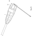
最終的に、図15は、エンクロージャーアセンブリ1の改良を示す。ここで、軸合わせアダプタ88は、コネクタ容積部78内に挿入されている。好ましくは、軸合わせアダプタ88は、コネクタ容積部78の前方開口89を完全に満たし、従って、前方向において、コネクタ容積部78を外側環境90に対して効果的に封止する。
Finally, FIG. 15 shows an improvement of the
軸合わせアダプタ88に、少なくとも1つのコネクタまたはカウンターコネクタのための相補的受容部91が設けられている。軸合わせアダプタ88は、電磁気遮蔽構造の内側に配置されている。
The
上述したようなエンクロージャーアセンブリ1は、いかなる干渉する遮蔽構造に対する注意を払う必要なしに、コネクタ容積部78内のコネクタ4をストランド24上に取り付けることができるという利点を有する。固定および可動のサブ構造20、44への遮蔽構造74の分割に起因して、遮蔽は、コネクタが取り付けられた後に、仕上げられてよい。この仕上げは、内側体62が前方にその操作位置にスライドされる場合に自動的に行われる。少なくとも、内側体62によって操作位置に達する場合に、固定および可動の遮蔽サブ構造は、内側体62のこの前方への移動の間に、自動的に互いに接触する。
The
容易にされたコネクタ4へのアクセスが重要でない場合に、重点は、低い製造コストに置かれてよい。ここで、遮蔽フェルール16および遮蔽要素46がケーブル上に固定された1つの一体化要素である単一の電磁気遮蔽構造は、好都合であり得る。この改良のために、上記は、また、変更すべきところは変更して、適用する。
Where access to the facilitated
上述した実施形態は、とりわけ、電力コネクタに適している。 The embodiments described above are particularly suitable for power connectors.
上記において、所定の構造が、「サブ構造」として記載されているが、これは、これらの構造が別の構造の部分であることを要求しない。固定遮蔽構造のみ、または磁気構造のみがある場合に、これらのサブ構造は、電磁気遮蔽構造全体を構成してよい。 In the above, certain structures have been described as “substructures”, but this does not require these structures to be part of another structure. If there is only a fixed shielding structure or only a magnetic structure, these substructures may constitute the entire electromagnetic shielding structure.
本発明に係るエンクロージャーアセンブリの遮蔽効果は、図16および17の比較からわかる。 The shielding effect of the enclosure assembly according to the present invention can be seen from a comparison of FIGS.
図16は、周波数において、3つの位置で測定された、後方向に伝播する、および前方向/後方向32、34に垂直な方向に配向した電磁場の強さを示す。測定位置は、エンクロージャーアセンブリの軸に沿って間隔があけられ、エンクロージャーアセンブリの前方において位置した、線Aと、エンクロージャーアセンブリの前方開口の平面において、線Bと、後方向において前方開口から間隔があけられた、線Cとである。 図16において、エンクロージャーアセンブリは、電磁気遮蔽構造を有さない。
Figure 16 shows the frequency was measured at three positions, propagates backward, and the strength of forward / electromagnetic field oriented in the
図17は、違いがエンクロージャーアセンブリに電磁気遮蔽構造74が設けられていることである、同じ測定を示す。
FIG. 17 shows the same measurement, the difference being that the enclosure assembly is provided with an
図16および17の比較からわかるように、エンクロージャーアセンブリ内の電磁場の強さは、広範囲の非常に高い周波数において約−70dBにおいて減少する。これは、非常に効果的な遮蔽をもたらす。 As can be seen from a comparison of FIGS. 16 and 17, the strength of the electromagnetic field in the enclosure assembly decreases at about −70 dB over a wide range of very high frequencies. This provides a very effective shielding.
Claims (18)
コネクタ容積部(78)が、該エンクロージャーアセンブリ(1)の内側体(62)内に位置し、コネクタ容積部(78)が、移動可能に収容されたコネクタ(4)を含み、内側体(62)が、前方向および後方向(32、42)において、外側環境(90)に開口していて、
外側体(68)が、内側体(62)上を前方向(42)にスライドするように内側体(62)と係合しており、
該外側体が、エンクロージャーアセンブリ(1)を嵌め合いエンクロージャーに固定するための少なくとも1つのロック要素(70)を含み、
コネクタ容積部(78)が、電磁気遮蔽構造(74)内に位置していて、電磁気遮蔽構造(74)が、内側体(62)内に位置していることを特徴とする、エンクロージャーアセンブリ(1)。 An enclosure assembly (1), provided for purposes of cable put that standardized the connector (12) (4), the enclosure assembly (1) is, the connector volume and (78), the outer Body (68),
A connector volume (78) is located within the inner body (62 ) of the enclosure assembly (1) , the connector volume (78) includes a connector (4) that is movably received, and the inner body (62 ) Open to the outer environment (90) in the forward and rearward directions (32, 42),
The outer body (68) engages the inner body (62) to slide forward (42) on the inner body (62) ;
The outer body includes at least one locking element (70) for mating and securing the enclosure assembly (1) to the enclosure;
An enclosure assembly (1) characterized in that the connector volume (78) is located in the electromagnetic shielding structure (74) and the electromagnetic shielding structure (74) is located in the inner body (62). ).
Applications Claiming Priority (2)
| Application Number | Priority Date | Filing Date | Title |
|---|---|---|---|
| EP11183866.0A EP2579396B1 (en) | 2011-10-04 | 2011-10-04 | Shielded enclosure assembly for at least one in particular standardized connector on a cable |
| EP11183866.0 | 2011-10-04 |
Publications (3)
| Publication Number | Publication Date |
|---|---|
| JP2013080705A JP2013080705A (en) | 2013-05-02 |
| JP2013080705A5 JP2013080705A5 (en) | 2015-11-12 |
| JP6051001B2 true JP6051001B2 (en) | 2016-12-21 |
Family
ID=44719695
Family Applications (1)
| Application Number | Title | Priority Date | Filing Date |
|---|---|---|---|
| JP2012221486A Active JP6051001B2 (en) | 2011-10-04 | 2012-10-03 | Shielding enclosure assembly for at least one specifically standardized connector in a cable |
Country Status (4)
| Country | Link |
|---|---|
| US (1) | US9153898B2 (en) |
| EP (1) | EP2579396B1 (en) |
| JP (1) | JP6051001B2 (en) |
| CN (1) | CN103036114B (en) |
Families Citing this family (32)
| Publication number | Priority date | Publication date | Assignee | Title |
|---|---|---|---|---|
| US8979592B2 (en) * | 2013-03-15 | 2015-03-17 | Carlisle Interconnect Technologies, Inc. | Electrical connector for high-speed data transmission |
| CN203225432U (en) * | 2013-04-02 | 2013-10-02 | 富士康(昆山)电脑接插件有限公司 | An electric connector assembly |
| KR101303784B1 (en) | 2013-06-24 | 2013-09-04 | (주)삼진탑테크엔지니어링 | Apartment house line connector |
| US9235010B2 (en) * | 2013-06-28 | 2016-01-12 | Commscope Technologies Llc | Robust optical crimp connector |
| US9874703B2 (en) * | 2014-05-21 | 2018-01-23 | Commscope Technologies Llc | Fiber optical cable assembly with sealed coupling mechanism |
| FR3022410B1 (en) * | 2014-06-12 | 2016-05-27 | Delphi Int Operations Luxembourg Sarl | SHIELDED ELECTRICAL CONNECTOR AND METHOD FOR MANUFACTURING THE SAME |
| EP2960695B1 (en) * | 2014-06-24 | 2020-08-12 | TE Connectivity Nederland B.V. | Connector for a cable and connector assembly |
| US9270048B2 (en) | 2014-06-26 | 2016-02-23 | Commscope Technologies Llc | Weatherized connector boot and connector cover therefore |
| EP2975700B1 (en) * | 2014-07-18 | 2019-08-21 | TE Connectivity Nederland B.V. | Enclosure assembly |
| CN104332761B (en) * | 2014-08-29 | 2018-01-16 | 中航光电科技股份有限公司 | Long unblock communication network interface plug and ethernet connector |
| DE102015200722A1 (en) * | 2015-01-19 | 2016-07-21 | Te Connectivity Germany Gmbh | Connector insert and connectors for data transmission in automobiles |
| EP3107155B8 (en) * | 2015-06-16 | 2019-01-16 | Aptiv Technologies Limited | Electrical connector system with shielding sleeve and method thereof |
| CN106450944A (en) * | 2015-08-07 | 2017-02-22 | 泰科电子(上海)有限公司 | Connector |
| CN105826707B (en) * | 2016-04-17 | 2018-06-08 | 江苏赛洋机电科技有限公司 | Connector shell is reliably connected structure with cable shield |
| EP3261193B1 (en) * | 2016-06-20 | 2018-11-28 | TE Connectivity Nederland B.V. | Enclosure assembly for a connector |
| CN106374252B (en) * | 2016-10-28 | 2019-02-15 | 河南天海电器有限公司 | A kind of multiconductor shielded connector |
| CN108811409B (en) * | 2017-05-04 | 2020-06-23 | 欧姆龙株式会社 | Electronic machine |
| CN107317128B (en) * | 2017-05-22 | 2019-04-30 | 张素平 | A kind of weak current cable connector of Anti-fall |
| DE102017111293A1 (en) * | 2017-05-23 | 2018-11-29 | Te Connectivity Germany Gmbh | pin |
| CN107396623B (en) * | 2017-07-31 | 2023-07-28 | 星展测控科技股份有限公司 | Electromagnetic shielding threading transition sleeve |
| DE102017118278A1 (en) * | 2017-08-10 | 2019-02-14 | Ims Connector Systems Gmbh | Spring sleeve for an electrical connector and connectors |
| CN107608033B (en) * | 2017-09-30 | 2019-05-31 | 武汉电信器件有限公司 | A kind of fiber adapter structure |
| DE102017218133A1 (en) * | 2017-10-11 | 2019-04-11 | Bayerische Motoren Werke Aktiengesellschaft | Screen transfer for a plug connection |
| EP3528348B1 (en) * | 2018-02-16 | 2021-12-08 | Aptiv Technologies Limited | Electrical shielding member for a network connector |
| CN110391559B (en) * | 2018-04-17 | 2021-06-29 | 泰科电子(上海)有限公司 | Connector with a locking member |
| CN110611180B (en) * | 2018-09-30 | 2021-05-18 | 中航光电科技股份有限公司 | Cable assembly and multi-core connector thereof |
| CN111384645B (en) * | 2018-12-28 | 2022-04-08 | 泰科电子(上海)有限公司 | Electrical connector and connector assembly |
| CN111384702B (en) * | 2018-12-28 | 2021-12-03 | 泰科电子(上海)有限公司 | Cable fixing device, cable connector and electrical equipment |
| CN111435777B (en) * | 2019-01-15 | 2022-07-22 | 泰科电子(上海)有限公司 | Electrical connector |
| FR3120483A1 (en) * | 2021-03-02 | 2022-09-09 | Aptiv Technologies Limited | Set of shielded connectors |
| DE102022114882A1 (en) | 2022-06-14 | 2023-12-14 | Te Connectivity Germany Gmbh | Shielding arrangement, shielded connection and kit for a shielding arrangement |
| EP4318816A1 (en) * | 2022-08-03 | 2024-02-07 | Aptiv Technologies Limited | Shielded and sealed connector |
Family Cites Families (30)
| Publication number | Priority date | Publication date | Assignee | Title |
|---|---|---|---|---|
| GB635089A (en) | 1946-03-02 | 1950-04-05 | Heyman Mfg Company | Improvements in or relating to strain-relief bushings |
| US3992773A (en) * | 1975-04-21 | 1976-11-23 | Grumman Aerospace Corporation | Magnetic forming process for joining electrical connectors and cables |
| GB2028009B (en) | 1978-08-10 | 1983-01-19 | Ward Goldstone Ltd | Electrical lead cable for a plug or connector |
| DE2848431A1 (en) | 1978-11-08 | 1980-05-14 | Bayer Ag | WATER-SOLUBLE, ULTRA-FILTRATABLE POLYURETHANE ANIONOMERS AND THEIR USE AS A FINISHING AGENT IN THE TEXTILE INDUSTRY |
| JPS58141586U (en) * | 1982-03-19 | 1983-09-24 | 富士通株式会社 | connector cover |
| EP0111162A1 (en) * | 1982-11-08 | 1984-06-20 | Microdot Inc. | Encapsulated, shielded, and grounded connector |
| US4493525A (en) * | 1983-01-31 | 1985-01-15 | Amp Incorporated | Electrical plug connector and receptacle therefor |
| JPH0224218Y2 (en) * | 1984-11-05 | 1990-07-03 | ||
| JPH0530307Y2 (en) * | 1987-02-12 | 1993-08-03 | ||
| US5060373A (en) * | 1989-08-22 | 1991-10-29 | The Phoenix Company Of Chicago, Inc. | Methods for making coaxial connectors |
| DE4107714C1 (en) * | 1991-03-11 | 1992-07-02 | Richard Hirschmann Gmbh & Co, 7300 Esslingen, De | Coaxial cable plug connector - has contact spring, whose middle portion is parallel to plug axis between plastics component free ends |
| US5618208A (en) * | 1994-06-03 | 1997-04-08 | Siemens Medical Systems, Inc. | Fully insulated, fully shielded electrical connector arrangement |
| US5465313A (en) | 1994-06-29 | 1995-11-07 | Molex Incorporated | Optical fiber connector and method of fabricating same |
| WO1997016871A1 (en) * | 1995-10-31 | 1997-05-09 | The Whitaker Corporation | Keying system for electrical connector |
| JP3396628B2 (en) * | 1998-07-16 | 2003-04-14 | 株式会社オートネットワーク技術研究所 | Shield connector |
| JP2002324627A (en) * | 2001-04-25 | 2002-11-08 | Yazaki Corp | Electromagnetic wave shielding structure |
| US6817902B2 (en) * | 2002-02-05 | 2004-11-16 | Amphenol Socapex | Plug device for a standard electrical or optical connection cord |
| US6752026B1 (en) * | 2002-02-09 | 2004-06-22 | Thomas Allen Hyde | Annular void electromagnetic flowmeter |
| US7234877B2 (en) * | 2004-10-27 | 2007-06-26 | Panduit Corp. | Fiber optic industrial connector |
| CN2785185Y (en) | 2005-03-15 | 2006-05-31 | 富士康(昆山)电脑接插件有限公司 | Electric connector assembly |
| US7251409B2 (en) | 2005-11-14 | 2007-07-31 | Microsoft Corporation | Cable strain relief design for limited space through-hole applications |
| US7316583B1 (en) * | 2006-08-22 | 2008-01-08 | Mencom Corporation | Field wireable network plug |
| US7338214B1 (en) | 2006-08-25 | 2008-03-04 | Tyco Electronics Corporation | Method and apparatus for sealing fiber optic connectors for industrial applications |
| US8070508B2 (en) | 2007-12-31 | 2011-12-06 | Nellcor Puritan Bennett Llc | Method and apparatus for aligning and securing a cable strain relief |
| CN201323333Y (en) * | 2008-12-11 | 2009-10-07 | 富士康(昆山)电脑接插件有限公司 | Cable connector component |
| US7988476B2 (en) * | 2009-04-09 | 2011-08-02 | Souriau Usa, Inc. | Sealed plug assembly |
| PL2759860T3 (en) | 2009-09-28 | 2018-07-31 | Te Connectivity Nederland B.V. | Sealing enclosure for a connector on a cable, such as a standardised fibre-optic connector |
| US8251748B2 (en) * | 2010-01-08 | 2012-08-28 | Tyco Electronics Corporation | Connector assembly having a cavity sealing plug |
| EP3451035B1 (en) * | 2010-02-03 | 2019-11-27 | Tyco Electronics Nederland B.V. | Enclosure assembly for a connector, strain relief element, and method |
| US8568167B2 (en) * | 2011-07-27 | 2013-10-29 | Ppc Broadband, Inc. | Coaxial cable connector having a breakaway compression sleeve |
-
2011
- 2011-10-04 EP EP11183866.0A patent/EP2579396B1/en active Active
-
2012
- 2012-09-28 CN CN201210366957.9A patent/CN103036114B/en active Active
- 2012-10-03 JP JP2012221486A patent/JP6051001B2/en active Active
- 2012-10-04 US US13/644,544 patent/US9153898B2/en active Active
Also Published As
| Publication number | Publication date |
|---|---|
| CN103036114B (en) | 2017-04-12 |
| EP2579396A1 (en) | 2013-04-10 |
| EP2579396B1 (en) | 2016-12-21 |
| JP2013080705A (en) | 2013-05-02 |
| CN103036114A (en) | 2013-04-10 |
| US9153898B2 (en) | 2015-10-06 |
| US20130084747A1 (en) | 2013-04-04 |
Similar Documents
| Publication | Publication Date | Title |
|---|---|---|
| JP6051001B2 (en) | Shielding enclosure assembly for at least one specifically standardized connector in a cable | |
| JP2013080705A5 (en) | ||
| KR102479155B1 (en) | Coaxial connector assembly | |
| KR101918428B1 (en) | Connector assembly | |
| CN110021854B (en) | Connector housing and connector | |
| JP5808043B2 (en) | Coaxial cable connector | |
| CN107528174B (en) | Housing assembly for connector | |
| EP3167512B1 (en) | Electrical connector for high-speed transmission using twisted-pair cable | |
| US8328579B2 (en) | Shield case and connector having the same | |
| JPH0577878U (en) | Plug type multi-pole connector | |
| US7147513B2 (en) | Shielded connector with insert molded shielding shell and resin cover | |
| JP2017168440A (en) | Electrical connection device, method of assembling electrical cable and assembled electrical coaxial cable | |
| JP6739793B2 (en) | Coaxial connector | |
| US6948977B1 (en) | Connector assembly and assembly method | |
| EP2761700B1 (en) | Shield connector and method of assembling shield connector | |
| MX2014006852A (en) | Cable header connector. | |
| JP2019503055A (en) | Connector assembly | |
| US8348681B2 (en) | Cable assembly | |
| KR20220013331A (en) | Method for crimping an electrical hf-connecting device | |
| US9391396B1 (en) | Latching arrangement for electrical connectors | |
| CN111934122B (en) | Male connector, female connector and connector assembly comprising male connector and female connector | |
| US8388378B2 (en) | Electrical connector | |
| EP2768087B1 (en) | Shield shell system and shield connector | |
| US20140065879A1 (en) | F-Connector with Chamfered Lock Ring | |
| US20220216651A1 (en) | Connector |
Legal Events
| Date | Code | Title | Description |
|---|---|---|---|
| A521 | Request for written amendment filed |
Free format text: JAPANESE INTERMEDIATE CODE: A523 Effective date: 20150924 |
|
| A621 | Written request for application examination |
Free format text: JAPANESE INTERMEDIATE CODE: A621 Effective date: 20150924 |
|
| RD04 | Notification of resignation of power of attorney |
Free format text: JAPANESE INTERMEDIATE CODE: A7424 Effective date: 20160218 |
|
| A977 | Report on retrieval |
Free format text: JAPANESE INTERMEDIATE CODE: A971007 Effective date: 20160715 |
|
| A131 | Notification of reasons for refusal |
Free format text: JAPANESE INTERMEDIATE CODE: A131 Effective date: 20160802 |
|
| A521 | Request for written amendment filed |
Free format text: JAPANESE INTERMEDIATE CODE: A523 Effective date: 20161020 |
|
| TRDD | Decision of grant or rejection written | ||
| A01 | Written decision to grant a patent or to grant a registration (utility model) |
Free format text: JAPANESE INTERMEDIATE CODE: A01 Effective date: 20161108 |
|
| A61 | First payment of annual fees (during grant procedure) |
Free format text: JAPANESE INTERMEDIATE CODE: A61 Effective date: 20161128 |
|
| R150 | Certificate of patent or registration of utility model |
Ref document number: 6051001 Country of ref document: JP Free format text: JAPANESE INTERMEDIATE CODE: R150 |
|
| R250 | Receipt of annual fees |
Free format text: JAPANESE INTERMEDIATE CODE: R250 |
|
| R250 | Receipt of annual fees |
Free format text: JAPANESE INTERMEDIATE CODE: R250 |
|
| R250 | Receipt of annual fees |
Free format text: JAPANESE INTERMEDIATE CODE: R250 |
|
| R250 | Receipt of annual fees |
Free format text: JAPANESE INTERMEDIATE CODE: R250 |
|
| R250 | Receipt of annual fees |
Free format text: JAPANESE INTERMEDIATE CODE: R250 |