JP6048330B2 - vending machine - Google Patents
vending machine Download PDFInfo
- Publication number
- JP6048330B2 JP6048330B2 JP2013144298A JP2013144298A JP6048330B2 JP 6048330 B2 JP6048330 B2 JP 6048330B2 JP 2013144298 A JP2013144298 A JP 2013144298A JP 2013144298 A JP2013144298 A JP 2013144298A JP 6048330 B2 JP6048330 B2 JP 6048330B2
- Authority
- JP
- Japan
- Prior art keywords
- vending machine
- predetermined time
- door
- input means
- setting input
- Prior art date
- Legal status (The legal status is an assumption and is not a legal conclusion. Google has not performed a legal analysis and makes no representation as to the accuracy of the status listed.)
- Active
Links
- 238000003780 insertion Methods 0.000 description 6
- 230000037431 insertion Effects 0.000 description 6
- 235000013361 beverage Nutrition 0.000 description 4
- 229910000831 Steel Inorganic materials 0.000 description 3
- 238000012790 confirmation Methods 0.000 description 3
- 230000006870 function Effects 0.000 description 3
- 238000000034 method Methods 0.000 description 3
- 239000010959 steel Substances 0.000 description 3
- 239000012141 concentrate Substances 0.000 description 2
- 238000001816 cooling Methods 0.000 description 2
- 238000010586 diagram Methods 0.000 description 2
- 238000010438 heat treatment Methods 0.000 description 2
- 239000011810 insulating material Substances 0.000 description 2
- 230000004308 accommodation Effects 0.000 description 1
- 230000002776 aggregation Effects 0.000 description 1
- 238000004220 aggregation Methods 0.000 description 1
- 238000005192 partition Methods 0.000 description 1
Images


Landscapes
- Control Of Vending Devices And Auxiliary Devices For Vending Devices (AREA)
Description
本発明は、設定入力手段を操作して、各種設定、各種確認作業などが行える自動販売機に関する。 The present invention relates to a vending machine capable of performing various settings and various confirmation operations by operating a setting input means.
従来の自動販売機は、設定装置(リモコン)を備え、この設定装置を操作して各種設定・確認作業を行っている。 A conventional vending machine includes a setting device (remote controller), and performs various setting / confirmation operations by operating the setting device.
この設定装置の操作後、販売待機状態に復帰させるには、設定装置の終了キーを押し、販売待機状態に復帰させていた(例えば、特許文献1参照)。 To return to the sales standby state after operating the setting device, the end key of the setting device is pressed to return to the sales standby state (see, for example, Patent Document 1).
上記構成において、設定装置の終了キーの操作を忘れると、販売待機状態に復帰しないため、販売できない状態が続いてしまう。 In the above configuration, if the user forgets to operate the end key of the setting device, the state does not return to the sales standby state, and the state where the sales cannot be continued continues.
そこで、終了キー操作忘れ防止により、販売待機状態に復帰しない不具合防止のため、終了キー以外のキー操作後、一定時間操作が無いと販売待機状態に復帰させるようにすることも考えられている。 Therefore, in order to prevent the end key operation from being forgotten, and to prevent the trouble of not returning to the sales standby state, it may be considered to return to the sales standby state if there is no operation for a certain period of time after a key operation other than the end key.
この一定時間は、作業員の作業には各種作業があるため、余裕を持って長い時間に設定してある場合があり、結果的に販売待機状態への復帰まで時間を要することがあった。 Since the worker's work includes various work, the fixed time may be set to a long time with a margin, and as a result, it may take time to return to the sales standby state.
本発明は、上記課題を解決するためになされたものであり、リモコン操作時からの販売待機状態への復帰を確実に行えるようにする自動販売機を提供することを目的とする。 The present invention has been made to solve the above-described problems, and an object of the present invention is to provide a vending machine capable of reliably returning to a sales standby state from the time of remote control operation.
上記目的を達成するために、本発明の自動販売機は、以下の手段により構成されるものである。
(1)設定・確認操作用の設定入力手段を備えた自動販売機において、前記設定入力手段が起動されてから、所定時間経過したら、前記設定入力手段の操作を無効として販売待機状態とするとともに、前面の扉の開閉状態を検知するドアスイッチを備え、前記ドアスイッチにより扉が開と検知している状態では、前記設定入力手段を操作中に所定時間経過した場合、所定時間を延長することを特徴とする。
(2)上記自動販売機において、所定時間を複数記憶し、設定入力手段の操作項目に基づいて、所定時間を変更することを特徴とする。
(3)上記自動販売機において、カレンダ機能を備え、予め設定された日は、所定時間を延長することを特徴とする。
In order to achieve the above object, the vending machine of the present invention comprises the following means.
(1) In a vending machine having setting input means for setting / confirming operation, when a predetermined time elapses after the setting input means is activated, the operation of the setting input means is invalidated to enter a sales standby state. A door switch for detecting the open / closed state of the front door, and in a state where the door is detected to be opened by the door switch, the predetermined time is extended when a predetermined time elapses during operation of the setting input means. It is characterized by.
(2) In the vending machine, a plurality of predetermined times are stored, and the predetermined times are changed based on an operation item of the setting input means.
(3) The vending machine is provided with a calendar function and extends a predetermined time on a preset date.
本発明は、設定入力手段が起動されてから、所定時間経過したら、前記設定入力手段の操作を無効として販売待機状態とすることにより、販売待機状態に復帰できないことが無くなる。 According to the present invention, when a predetermined time elapses after the setting input unit is activated, the operation of the setting input unit is invalidated to enter the sales standby state, so that it is not possible to return to the sales standby state.
また、ドアスイッチの検知により、所定時間を延長できるため、作業者にとっては、作業時間が長く掛かる場合であっても、時間を意識することなく、作業に集中できる。 Moreover, since the predetermined time can be extended by detecting the door switch, even if the worker takes a long time, the worker can concentrate on the work without being aware of the time.
さらに、操作項目、設定された日によって所定時間が自動的に変更されるため、時間を意識することなく、作業に集中できる。 Furthermore, since the predetermined time is automatically changed according to the operation item and the set date, it is possible to concentrate on the work without being aware of the time.
以下に図面を参照しながら、本発明に係る自動販売機の実施の形態について説明する。 Embodiments of a vending machine according to the present invention will be described below with reference to the drawings.
まず、本発明の対象となる自動販売機の一例を図5.図6を用いて説明するものであり、図5は概略正面図、図6は外扉を開放した状態における概略斜視図である。 First, an example of a vending machine as an object of the present invention is shown in FIG. FIG. 5 is a schematic front view, and FIG. 6 is a schematic perspective view in a state where the outer door is opened.
ここで例示する自動販売機1は、缶入り飲料やペットボトル入り飲料、ビン入り飲料、缶ボトル入り飲料等の商品を冷却、もしくは加熱した状態で販売するためのもので、本体キャビネット10を備えている。本体キャビネット10は、複数の鋼板を組み合わせることによって構成したもので、前面が開口した箱状を成している。
The
本体キャビネット10の内部には、内箱20が設けてある。内箱20は、本体キャビネット10と同様に、複数の鋼板を組み合わせることにより、前面が開口した箱状に構成したものである。図には明示していないが、本体キャビネット10と内箱20との間には、内箱20の内部を断熱構造とするために断熱材が充填してある。
An
内箱20の内部には、複数の収容室21が設けてある。複数の収容室21は、内箱20の内部に断熱仕切壁22を設けることによって構成したもので、互いに熱的に独立している。各収容室21の下方部には、シュータ23が設けてある。シュータ23は、商品収納ラック30から払い出された商品を案内するためのもので、手前側に向けて下方に傾斜している。図には明示していないが、収容室21の内部においてシュータ23より下方となる領域には、内部を所望の温度に維持するための冷却ユニットや加熱ユニットが設けてある。
A plurality of
また、上記自動販売機1には、本体キャビネット10の一側縁部に内扉40及び外扉50を保持させてある。内扉40は、収容室21の前面開口を開閉するためのもので、中空の鋼板パネルに断熱材を充填する等、断熱機能を有するように構成してある。外扉50は、本体キャビネット10の前面開口を開閉するためのものである。
Further, the
外扉50の前面には、上部に商品見本展示室51と、該展示室51内に配置される複数の商品見本52と、該商品見本52に対応して設けられる販売可能ランプおよび売切ランプを備える商品選択ボタン53と、紙幣を挿入する紙幣挿入口54と、硬貨を投入する硬貨投入口55と、投入貨幣を返却する返却レバー56と、釣銭などを返却する硬貨返却口55aと、投入金額表示を行う金額表示を含む一体表示器57と、シュータ23によって案内された商品を取り出すための商品取出口58と、シリンダー錠付きのハンドル59とが設けてある。
On the front surface of the
また、外扉50の裏面側には、メインコントロールボックス101、各種設定・確認操作用の設定入力手段としてのリモコン102、硬貨投入口55から投入された硬貨の真偽、種類などを選別し、計数および釣銭を払い出す硬貨処理装置103、紙幣挿入口54から挿入された紙幣の真偽、種類などを識別する紙幣識別装置104などが配置されている。
Further, on the back side of the
なお、外扉50には、外扉の開閉を検知するためのドアスイッチ50aが設けられている。
The
次に、図1は、本発明の実施例を示すブロック図であり、メインコントロールボックス101内には、自動販売機全体を制御する制御部101a、制御プログラムを記憶するメモリ101b、自動販売機の動作に係る設定データを含む各種データを記憶するメモリ101c、外扉50が閉じられてからの時間、リモコンの未操作時間など計測するタイマ101dなどを備える。
FIG. 1 is a block diagram showing an embodiment of the present invention. In a
このメインコントロールボックス101には、各種設定・確認操作用の設定入力手段としてのリモコン102、硬貨投入口55から投入された硬貨の真偽、種類などを選別し、計数および釣銭を払い出す硬貨処理装置103、紙幣挿入口54から挿入された紙幣の真偽、種類などを識別する紙幣識別装置104、冷却機およびヒータなどからなる冷熱装置105,商品を搬出する商品搬出装置106を制御する本体制御部107、販売可能ランプ53aおよび売切ランプ53bを備える商品選択ボタン53、一体表示器57、ドアスイッチ50aがそれぞれ接続されている。
The
なお、硬貨処理装置103には、返却レバー56が接続されており、通常時の操作においては、この返却レバー56を操作することにより、保留中の硬貨あるいは紙幣が返却されるものである。
In addition, the
また、ドアスイッチ50aは、外扉50が閉移動して本体キャビネット10の前面開口が閉じられた場合にオフ状態となる一方、外扉50が開移動して本体キャビネット10の前面開口が開放された場合にオン状態となる。
The
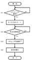
この構成において、図2のフローチャート図を用い、第1の実施形態について、その制御動作を説明する。 In this configuration, the control operation of the first embodiment will be described with reference to the flowchart of FIG.
まず、リモコン102が操作されたかを判断し(ステップS01)、操作されたことを検知すると(ステップS01,Yes)、タイマ101dのカウントがスタートする(ステップS02)。次に、タイマ101dによるカウントが予め設定されている所定時間を経過したかを判断し(ステップS03)、所定時間が経過すると(ステップS03,Yes)、リモコン操作を強制終了させて(ステップS04)、販売待機状態へ戻る(ステップS05)。
First, it is determined whether or not the
次に、図3のフローチャート図を用い、第2の実施形態について、その制御動作を説明する。 Next, the control operation of the second embodiment will be described using the flowchart of FIG.
まず、リモコン102が操作されたかを判断し(ステップS11)、操作されたことを検知すると(ステップS11,Yes)、タイマ101dのカウントがスタートする(ステップS12)。次に、タイマ101dによるカウントが予め設定されている所定時間を経過したかを判断し(ステップS13)、所定時間が経過すると(ステップS13,Yes)、ドアスイッチ50aがオンで、外扉50が開放状態かを判断し(ステップS14)、外扉50が開放状態であれば(ステップS14,Yes)、リモコン102の操作中かを判断し(ステップS15)、リモコン102の操作中であれば(ステップS15,Yes)、リモコン102の操作可能な所定時間を延長する(ステップS16)。
First, it is determined whether the
一方、ドアスイッチ50aがオフで外扉50が閉じられている状態であれば(ステップS14,No)、リモコン102を終了させて(ステップS18)、販売待機状態へ戻る(ステップS19)。
On the other hand, if the
また、ステップS15にて、リモコン102が操作中で無ければ(ステップS15,No)、リモコン102を終了させて(ステップS18)、販売待機状態へ戻る(ステップS19)。
If the
次に、リモコン102の操作可能な延長時間が経過すると(ステップS17,Yes)、再度、ドアスイッチ50aがオンで、外扉50が開放状態かを判断し(ステップS14)、外扉50が開放状態でなければ(ステップS14,No)、リモコン102を終了させて(ステップS18)、販売待機状態へ戻る(ステップS19)。
Next, when the extended time during which the
なお、上記図3の処理では、延長時間経過後、ドアスイッチ50aがオンで、外扉50が開放状態であれば、再延長も可能であり、外扉50が開放していても、リモコン102が操作中でなければ、リモコン102を終了させて、販売待機状態へ戻る。
In the process of FIG. 3 described above, if the
また、ドアスイッチ50aの状態に関係なく、延長を1回とし、延長時間が経過すれば、リモコン102を終了させて、販売待機状態へ戻るようにしてもよい。
Further, regardless of the state of the
次に、作業内容によって、所定時間を変更する場合については、例えば、複数の商品の入れ替えを行う際には、現収納商品の払出、新規商品の投入、設定作業などが必要であり、また、売上集計作業は作業量が多いため、このような設定モードが選択させた場合には、所定時間を長くするようにすることで、所定時間を意識することなく、作業が可能となる。 Next, when changing the predetermined time according to the work content, for example, when replacing a plurality of products, it is necessary to pay out the current stored product, input a new product, setting work, etc. Since the sales counting work has a large work amount, when such a setting mode is selected, the work can be performed without being aware of the predetermined time by making the predetermined time longer.
また、カレンダ機能を有する場合には、売上集計日を設定しておき、この日の作業は所定時間を長くするようにすることで、所定時間を意識することなく、作業が可能となる。 In addition, when the calendar function is provided, a sales aggregation date is set, and the work on this day can be performed without being aware of the predetermined time by extending the predetermined time.
1 自動販売機
10 本体キャビネット
50 外扉
50a ドアスイッチ
101 メインコントロールボックス
101a 制御部
101b メモリ
101c メモリ
101d タイマ
102 リモコン
DESCRIPTION OF
Claims (3)
Priority Applications (1)
| Application Number | Priority Date | Filing Date | Title |
|---|---|---|---|
| JP2013144298A JP6048330B2 (en) | 2013-07-10 | 2013-07-10 | vending machine |
Applications Claiming Priority (1)
| Application Number | Priority Date | Filing Date | Title |
|---|---|---|---|
| JP2013144298A JP6048330B2 (en) | 2013-07-10 | 2013-07-10 | vending machine |
Publications (2)
| Publication Number | Publication Date |
|---|---|
| JP2015018356A JP2015018356A (en) | 2015-01-29 |
| JP6048330B2 true JP6048330B2 (en) | 2016-12-21 |
Family
ID=52439301
Family Applications (1)
| Application Number | Title | Priority Date | Filing Date |
|---|---|---|---|
| JP2013144298A Active JP6048330B2 (en) | 2013-07-10 | 2013-07-10 | vending machine |
Country Status (1)
| Country | Link |
|---|---|
| JP (1) | JP6048330B2 (en) |
Family Cites Families (1)
| Publication number | Priority date | Publication date | Assignee | Title |
|---|---|---|---|---|
| JPS57199086A (en) * | 1981-05-30 | 1982-12-06 | Nippon Coinco Co Ltd | Article price setter for vending machine |
-
2013
- 2013-07-10 JP JP2013144298A patent/JP6048330B2/en active Active
Also Published As
| Publication number | Publication date |
|---|---|
| JP2015018356A (en) | 2015-01-29 |
Similar Documents
| Publication | Publication Date | Title |
|---|---|---|
| JP5884395B2 (en) | vending machine | |
| JP2008097211A (en) | Vending machine | |
| JP6048330B2 (en) | vending machine | |
| JP5668545B2 (en) | Product storage device | |
| JP5696500B2 (en) | vending machine | |
| JP5163371B2 (en) | vending machine | |
| JP2008027333A (en) | Automatic vending machine | |
| JP5906639B2 (en) | vending machine | |
| JP2013089179A (en) | Automatic vending machine | |
| JP5906603B2 (en) | vending machine | |
| JP2008015808A (en) | Vending machine | |
| JP2015018357A (en) | Automatic vending machine | |
| JP4995742B2 (en) | vending machine | |
| JP5577923B2 (en) | vending machine | |
| JP5625595B2 (en) | vending machine | |
| JP5428698B2 (en) | vending machine | |
| JP4306437B2 (en) | vending machine | |
| JP5169349B2 (en) | Product price control device for vending machines | |
| JP5691963B2 (en) | vending machine | |
| CN104637165A (en) | Automatic vending machine | |
| JP5272591B2 (en) | Vending machine control equipment | |
| JP2002157635A (en) | Automatic vending machine | |
| JP4793231B2 (en) | Card dispensing device | |
| JP5668546B2 (en) | Product storage device | |
| JP5742328B2 (en) | Product storage device |
Legal Events
| Date | Code | Title | Description |
|---|---|---|---|
| RD02 | Notification of acceptance of power of attorney |
Free format text: JAPANESE INTERMEDIATE CODE: A7422 Effective date: 20151005 |
|
| RD04 | Notification of resignation of power of attorney |
Free format text: JAPANESE INTERMEDIATE CODE: A7424 Effective date: 20151005 |
|
| A621 | Written request for application examination |
Free format text: JAPANESE INTERMEDIATE CODE: A621 Effective date: 20151210 |
|
| A977 | Report on retrieval |
Free format text: JAPANESE INTERMEDIATE CODE: A971007 Effective date: 20160810 |
|
| A131 | Notification of reasons for refusal |
Free format text: JAPANESE INTERMEDIATE CODE: A131 Effective date: 20160816 |
|
| A521 | Request for written amendment filed |
Free format text: JAPANESE INTERMEDIATE CODE: A523 Effective date: 20161007 |
|
| TRDD | Decision of grant or rejection written | ||
| A01 | Written decision to grant a patent or to grant a registration (utility model) |
Free format text: JAPANESE INTERMEDIATE CODE: A01 Effective date: 20161025 |
|
| A61 | First payment of annual fees (during grant procedure) |
Free format text: JAPANESE INTERMEDIATE CODE: A61 Effective date: 20161107 |
|
| R150 | Certificate of patent or registration of utility model |
Ref document number: 6048330 Country of ref document: JP Free format text: JAPANESE INTERMEDIATE CODE: R150 |
|
| R250 | Receipt of annual fees |
Free format text: JAPANESE INTERMEDIATE CODE: R250 |
|
| R250 | Receipt of annual fees |
Free format text: JAPANESE INTERMEDIATE CODE: R250 |
|
| R250 | Receipt of annual fees |
Free format text: JAPANESE INTERMEDIATE CODE: R250 |
|
| R250 | Receipt of annual fees |
Free format text: JAPANESE INTERMEDIATE CODE: R250 |
|
| R250 | Receipt of annual fees |
Free format text: JAPANESE INTERMEDIATE CODE: R250 |