JP6045702B2 - Method, control device and system for determining tread depth of tire tread - Google Patents
Method, control device and system for determining tread depth of tire tread Download PDFInfo
- Publication number
- JP6045702B2 JP6045702B2 JP2015527942A JP2015527942A JP6045702B2 JP 6045702 B2 JP6045702 B2 JP 6045702B2 JP 2015527942 A JP2015527942 A JP 2015527942A JP 2015527942 A JP2015527942 A JP 2015527942A JP 6045702 B2 JP6045702 B2 JP 6045702B2
- Authority
- JP
- Japan
- Prior art keywords
- tire
- instantaneous
- wheel
- vehicle
- tread
- Prior art date
- Legal status (The legal status is an assumption and is not a legal conclusion. Google has not performed a legal analysis and makes no representation as to the accuracy of the status listed.)
- Active
Links
- 238000000034 method Methods 0.000 title claims description 43
- 230000001133 acceleration Effects 0.000 claims description 14
- 238000003860 storage Methods 0.000 claims description 14
- 238000004519 manufacturing process Methods 0.000 claims description 8
- 238000001514 detection method Methods 0.000 claims description 4
- 230000003287 optical effect Effects 0.000 claims description 3
- 238000005096 rolling process Methods 0.000 description 8
- 230000005540 biological transmission Effects 0.000 description 5
- 230000008859 change Effects 0.000 description 4
- 230000001419 dependent effect Effects 0.000 description 4
- 238000013459 approach Methods 0.000 description 3
- 230000009471 action Effects 0.000 description 2
- 238000010586 diagram Methods 0.000 description 2
- 230000000694 effects Effects 0.000 description 2
- 230000006870 function Effects 0.000 description 2
- 238000005259 measurement Methods 0.000 description 2
- 230000002457 bidirectional effect Effects 0.000 description 1
- 238000009530 blood pressure measurement Methods 0.000 description 1
- 238000009529 body temperature measurement Methods 0.000 description 1
- 238000004891 communication Methods 0.000 description 1
- 230000001010 compromised effect Effects 0.000 description 1
- 238000011217 control strategy Methods 0.000 description 1
- 238000011161 development Methods 0.000 description 1
- 230000018109 developmental process Effects 0.000 description 1
- 238000001914 filtration Methods 0.000 description 1
- 230000004927 fusion Effects 0.000 description 1
- 238000009434 installation Methods 0.000 description 1
- 230000003993 interaction Effects 0.000 description 1
- 238000012544 monitoring process Methods 0.000 description 1
- 230000008569 process Effects 0.000 description 1
- 230000009467 reduction Effects 0.000 description 1
- 229920006395 saturated elastomer Polymers 0.000 description 1
- XLYOFNOQVPJJNP-UHFFFAOYSA-N water Substances O XLYOFNOQVPJJNP-UHFFFAOYSA-N 0.000 description 1
Images


Classifications
-
- B—PERFORMING OPERATIONS; TRANSPORTING
- B60—VEHICLES IN GENERAL
- B60C—VEHICLE TYRES; TYRE INFLATION; TYRE CHANGING; CONNECTING VALVES TO INFLATABLE ELASTIC BODIES IN GENERAL; DEVICES OR ARRANGEMENTS RELATED TO TYRES
- B60C11/00—Tyre tread bands; Tread patterns; Anti-skid inserts
- B60C11/24—Wear-indicating arrangements
- B60C11/246—Tread wear monitoring systems
-
- B—PERFORMING OPERATIONS; TRANSPORTING
- B60—VEHICLES IN GENERAL
- B60C—VEHICLE TYRES; TYRE INFLATION; TYRE CHANGING; CONNECTING VALVES TO INFLATABLE ELASTIC BODIES IN GENERAL; DEVICES OR ARRANGEMENTS RELATED TO TYRES
- B60C11/00—Tyre tread bands; Tread patterns; Anti-skid inserts
- B60C11/24—Wear-indicating arrangements
- B60C11/243—Tread wear sensors, e.g. electronic sensors
-
- G—PHYSICS
- G07—CHECKING-DEVICES
- G07C—TIME OR ATTENDANCE REGISTERS; REGISTERING OR INDICATING THE WORKING OF MACHINES; GENERATING RANDOM NUMBERS; VOTING OR LOTTERY APPARATUS; ARRANGEMENTS, SYSTEMS OR APPARATUS FOR CHECKING NOT PROVIDED FOR ELSEWHERE
- G07C5/00—Registering or indicating the working of vehicles
- G07C5/006—Indicating maintenance
-
- G—PHYSICS
- G07—CHECKING-DEVICES
- G07C—TIME OR ATTENDANCE REGISTERS; REGISTERING OR INDICATING THE WORKING OF MACHINES; GENERATING RANDOM NUMBERS; VOTING OR LOTTERY APPARATUS; ARRANGEMENTS, SYSTEMS OR APPARATUS FOR CHECKING NOT PROVIDED FOR ELSEWHERE
- G07C5/00—Registering or indicating the working of vehicles
- G07C5/08—Registering or indicating performance data other than driving, working, idle, or waiting time, with or without registering driving, working, idle or waiting time
- G07C5/0808—Diagnosing performance data
Landscapes
- Engineering & Computer Science (AREA)
- Mechanical Engineering (AREA)
- Physics & Mathematics (AREA)
- General Physics & Mathematics (AREA)
- Control Of Driving Devices And Active Controlling Of Vehicle (AREA)
- Tires In General (AREA)
- Regulating Braking Force (AREA)
Description
本発明は、タイヤを有する車両の動作中に、このタイヤのトレッドのトレッドデプスを求めるための方法と、車両のタイヤのトレッドのトレッドデプスを求めるための車両用の制御装置およびシステムに関する。 The present invention relates to a method for determining the tread depth of a tread of a tire during operation of a vehicle having a tire, and a control device and system for a vehicle for determining the tread depth of a tread of a vehicle tire.
WO 02/12003 A2からは、車両の複数の車輪の各車輪の状態を監視するための装置が公知である。この装置は、コンピュータと、車輪回転速度算出システムと、車速信号発生器とを有しており、上記の車輪回転速度算出システムは、各車輪について複数の車輪回転速度を形成し、かつ、上記のコンピュータに接続されており、これによって車輪毎に複数の回転速度信号をこのコンピュータに伝送する。さらに上記の装置は、コンピュータ記憶装置を有しており、このコンピュータ記憶装置には、複数の車輪のそれぞれに取り付けられたタイヤに対するタイヤ摩耗率と、装着以来のタイヤ積算距離値、現在の走行の走行距離と、平均車輪回転速度と、車両速度信号に基づいて車輪速度を推定するためのスケーリングファクタとに関するデータが記憶されている。さらにこの装置は、上記のコンピュータ上で実行するための記憶されたプログラムを有しており、このプログラムは、許容限界外にある、妥協的な複数の動作条件を特徴付ける車輪速度を求める際に上記の記憶されたデータを参照する。 From WO 02/12003 A2, an apparatus for monitoring the state of each wheel of the plurality of wheels of the vehicle are known. The apparatus includes a computer, a wheel rotation speed calculation system, and a vehicle speed signal generator. The wheel rotation speed calculation system forms a plurality of wheel rotation speeds for each wheel , and A plurality of rotational speed signals are transmitted to the computer for each wheel . Further, the above-mentioned device has a computer storage device, and in this computer storage device, the tire wear rate for the tire attached to each of the plurality of wheels , the tire integrated distance value since installation, Data relating to the travel distance, the average wheel rotation speed, and the scaling factor for estimating the wheel speed based on the vehicle speed signal is stored. In addition, the apparatus has a stored program for execution on the computer described above, which is used in determining wheel speeds characterizing a plurality of compromised operating conditions that are outside acceptable limits. Refer to the stored data.
本発明の課題は、タイヤのトレッドのトレッドデプスを求めるための方法、制御装置およびシステムを提供して、タイヤを有する車両の動作中にトレッドデプスが一層良好に求められるようにすることである。 It is an object of the present invention to provide a method, control device and system for determining the tread depth of a tire tread so that the tread depth is better determined during operation of a vehicle having a tire.
この課題は、独立請求項が対象とするものよって解決される。有利な実施形態は、従属請求項に記載されている。 This problem is solved by the subject matter of the independent claims. Advantageous embodiments are described in the dependent claims.
タイヤを有する車両の動作中にタイヤのトレッドのトレッドデプスを求める本発明の方法は、本発明の一態様において以下のようなステップを有する。ここでは、少なくとも1つの第1センサによって求めたデータに基づいて、タイヤを装着した車両の車輪の瞬時回転速度を求める。さらに、上記の少なくとも1つの第1センサとは異なる少なくとも1つの第2センサによって求めたデータに基づいて上記の車両の瞬時速度を求める。さらに、上記の求めた瞬時回転速度および求めた瞬時速度に基づいて、タイヤを装着した上記の車輪の瞬時の動的な半径を求める。さらに、瞬時タイヤ温度、瞬時タイヤ空気圧および瞬時タイヤ負荷からなるグループから選択した、上記のタイヤの少なくとも1つの第1パラメタを求める。さらに、上記の求めた少なくとも1つの第1パラメタに基づいて、車輪の瞬時の動的な内径を求める。ここでこの車輪の内径は、車輪中心と前トレッドのタイヤ側の始端部との間の間隔である。ここではさらに、上記の求めた瞬時の動的な半径と、求めた瞬時の動的な内径とに基づいてタイヤのトレッドのトレッドデプスを求める。 The method of the present invention for determining the tread depth of a tire tread during operation of a vehicle having a tire includes the following steps in one aspect of the present invention. Here, the instantaneous rotational speed of the wheel of the vehicle equipped with the tire is obtained based on the data obtained by the at least one first sensor. Further, the instantaneous speed of the vehicle is obtained based on data obtained by at least one second sensor different from the at least one first sensor. Further, based on the obtained instantaneous rotation speed and the obtained instantaneous speed, the instantaneous dynamic radius of the wheel on which the tire is mounted is obtained. Further, at least one first parameter of the tire selected from the group consisting of instantaneous tire temperature, instantaneous tire pressure, and instantaneous tire load is obtained. Further, the instantaneous dynamic inner diameter of the wheel is obtained based on the obtained at least one first parameter. Wherein the inner diameter of the wheel is the distance between the starting end of the tire side of the wheel center and the front tread. Further, the tread depth of the tire tread is obtained based on the obtained instantaneous dynamic radius and the obtained instantaneous dynamic inner diameter.
ここおよび以下で、瞬時の動的な半径とは、剛性車輪が有するつぎのような半径のことである。すなわち、この剛性車輪の半径は、所定の速度において、上記のタイヤを装着した車輪がこの速度において有する転がり周長と等しい転がり周長を剛性車輪が有するようにするための半径のことである。ここで転がり周長とは、車輪が一回転時にスリップなし進む長さのことである。さらに上記の動的な半径は、動的な車輪半径または動的な転がり半径とも称される。上記の瞬時の動的な内径とは、車輪中心と、上記の剛性車輪のトレッドのタイヤ側の始端部、つまり所定の速度において、上記のタイヤを装着した車輪がこの速度において有する転がり周長に等しくなるような車輪のトレッドのタイヤ側の始端部との間の間隔のことである。 Here and below, the instantaneous dynamic radius is the following radius of the rigid wheel . That is, the radius of the rigid wheel is a radius for causing the rigid wheel to have a rolling circumference equal to the rolling circumference of the wheel fitted with the tire at the predetermined speed. Here, the rolling circumference is the length that the wheel travels without slipping during one rotation. Furthermore, the dynamic radius is also referred to as a dynamic wheel radius or a dynamic rolling radius. The instantaneous dynamic inner diameter refers to the rolling circumference of the wheel center and the starting end of the rigid wheel tread on the tire side, i.e., the wheel on which the tire is mounted at a predetermined speed. This is the distance between the tire tread and the tire end of the wheel tread.
上記の実施形態による方法により、車両の動作中に、タイヤのトレッドデプスを一層良好に求めることができる。これは、殊に上記の瞬時の動的な半径を求めることと、求めた上記の少なくとも1つのパラメタに基づいて上記の瞬時の動的な内径を求めることと、これら量に基づいてトレッドデプスを求めることとによって行われる。ここでは、以下に詳しく説明するように、上記の車輪の動的な半径が、この車輪の上記の瞬時の動的な内径と、タイヤのトレッドのトレッドデプスとから成り、かつ、この車輪の上記の瞬時の動的な内径が上記の少なくとも1つのパラメタに依存するという考察から出発している。したがって上記の少なくとも1つの第1パラメタを求めることにより、この車輪の都度の瞬時の動的な内径を求めることができ、ひいては上記のトレッドデプスを、可能な限りに正確な範囲に求めることができるのである。 By the method according to the above-described embodiment, the tread depth of the tire can be obtained better during the operation of the vehicle. In particular, determining the instantaneous dynamic radius, determining the instantaneous dynamic inner diameter based on the determined at least one parameter, and determining the tread depth based on these quantities. By seeking. Here, as described in detail below, the dynamic radius of the wheel is composed of a dynamic inner diameter of the instantaneous this wheel, the tread depth of the tire tread, and, above this wheel We start with the consideration that the instantaneous dynamic inner diameter of is dependent on at least one of the above parameters. Therefore, by obtaining the at least one first parameter, the instantaneous dynamic inner diameter of each wheel can be obtained, and thus the tread depth can be obtained in an accurate range as much as possible. It is.
上記の少なくとも1つの第1センサは一般的に、回転数センサとして構成されている。すなわち、上記の車輪の瞬時回転速度は、この実施形態において少なくとも1つの回転数センサによって求めたデータに基づいて求められるのである。これにより、この車輪の回数速度を簡単かつ高い信頼性で求めることができる。 The at least one first sensor is generally configured as a rotational speed sensor. That is, the instantaneous rotational speed of the wheel is obtained based on data obtained by at least one rotational speed sensor in this embodiment. As a result, the speed of this wheel can be determined easily and with high reliability.
上記の車輪の瞬時回転速度の算出には一般的に、この車輪の瞬時角速度の算出が含まれている。 The calculation of the instantaneous rotational speed of the wheel generally includes calculation of the instantaneous angular speed of the wheel .
上記の少なくとも1つの第2センサは有利には、衛星支援位置検出センサと、レーダセンサと、ライダセンサと、超音波センサと、光学式カメラとからなるグループから選択される。これらのセンサを用いれば、回転数ベースの速度算出とは無関係に車両の瞬時速度を求めることができ、上記の瞬時の動的な半径の算出ひいてはトレッドデプスの算出に対し、独立した車両基準速度を供給することができる。 Said at least one second sensor is advantageously selected from the group consisting of a satellite assisted position detection sensor, a radar sensor, a lidar sensor, an ultrasonic sensor and an optical camera. By using these sensors, the instantaneous speed of the vehicle can be obtained independently of the speed-based speed calculation. Independent of the above-mentioned instantaneous dynamic radius calculation and thus the tread depth calculation, an independent vehicle reference speed is obtained. Can be supplied.
上記の方法の別の実施形態ではさらに、上記の車輪の瞬時の動的な内径の算出は、上記の車両の求めた瞬時速度に基づいて行われる。ここでは、上記の車輪の瞬時の動的な内径は、上記ですでに挙げた量に他にさらに、以下でさらに説明するように上記の瞬時速度に依存するという考察から出発している。これにより、ここで挙げた実施形態によって車輪の都度の瞬時の動的な内径をさらに改善して求めることができる。 In yet another embodiment of the above method, the instantaneous dynamic inner diameter of the wheel is calculated based on the instantaneous speed determined by the vehicle. Here, we start with the consideration that the instantaneous dynamic inner diameter of the wheel depends on the instantaneous speed as described further below, in addition to the quantities already mentioned above. Thereby, it is possible to further improve the instantaneous dynamic inner diameter of each wheel according to the embodiment described here.
さらに上記の車輪の瞬時の動的な内径は、タイヤのタイプおよび/またはタイヤの製造後経過年数に基づいて求めることができる。これらのパラメタも車輪の内径に影響を及ぼすことがあり、したがって有利には上記の内径を求める際にも考慮される。 Furthermore, the instantaneous dynamic inner diameter of the wheel can be determined based on the type of tire and / or the number of years since manufacture of the tire. These parameters can also influence the inner diameter of the wheel and are therefore advantageously taken into account when determining the inner diameter.
上記の車輪の瞬時の動的な内径の算出は、例えば、記憶装置に格納された少なくとも1つの特性曲線を用いて行われる。この少なくとも1つの特性曲線は、車輪の少なくとも1つの第1パラメタと車輪の内径との間、車両の速度と車輪の内径との間、タイヤタイプと車輪の内径との間、および/または、タイヤの製造後経過年数と車輪の内径との間の関係を表す。 The instantaneous dynamic inner diameter of the wheel is calculated using, for example, at least one characteristic curve stored in the storage device. The at least one characteristic curve, between at least one first parameter and the wheel of the inner diameter of the wheel, between the velocity and the wheel of the inner diameter of the vehicle, between the inner diameter of the tire type and the wheel, and / or the tire Represents the relationship between the number of years since the manufacture of the wheel and the inner diameter of the wheel .
上記の少なくとも1つの特性曲線は、上記の車輪のモデルをベースにすることができる。すなわち、上で挙げた複数の量と、車輪の内径との間の関係は、この実施形態においてすでに記憶装置に前もって格納されているのである。また上記の少なくとも1つの特性曲線は、車両の走行動作中に求めることができる。したがって最後に挙げた実施形態では、各特性曲線はまず学習フェーズにおいて、一般的には新しい車輪を車両に取り付けた後に求められ、以降は上記の瞬時の動的な内径を求めるために使用されるのである。 The at least one characteristic curve may be based on the wheel model described above. That is, the relationship between the quantities listed above and the inner diameter of the wheel is already stored in advance in the storage device in this embodiment. Further, the at least one characteristic curve can be obtained during the traveling operation of the vehicle. Thus, in the last mentioned embodiment, each characteristic curve is first determined in the learning phase, generally after a new wheel is mounted on the vehicle, and thereafter used to determine the instantaneous dynamic inner diameter described above. It is.
上記の方法の別の実施形態ではさらに、車両の瞬時加速度と、車両の瞬時ヨーレートと、瞬時操舵角と、車両の駆動原動機の瞬時回転トルクと、車両の制動装置の動作状態とからなるグループから選択した少なくとも1つの第2パラメタを求める。この実施形態では、求めたこの少なくとも1つの第2パラメタに依存して、タイヤのトレッドのトレッドデプスを求める。ここでは、駆動スリップないしは制動スリップの影響が小さく、かつ、車両が直線的に運動する走行状況中に、可能な限り正確な範囲で上記のトレッドデプスを求めることができるという考察から出発している。上で挙げたパラメタを用いれば、このような走行状況を容易に識別することができ、さらに駆動スリップないし制動スリップおよび路面の湾曲の影響を補償することができる。 In another embodiment of the above method, the method further includes a group consisting of an instantaneous acceleration of the vehicle, an instantaneous yaw rate of the vehicle, an instantaneous steering angle, an instantaneous rotational torque of the driving motor of the vehicle, and an operating state of the braking device of the vehicle. Determine at least one selected second parameter. In this embodiment, the tread depth of the tire tread is determined depending on the determined at least one second parameter. Here, we start with the consideration that the tread depth can be determined in the most accurate range possible during a driving situation where the influence of the driving slip or braking slip is small and the vehicle moves linearly. . By using the parameters listed above, it is possible to easily identify such traveling conditions, and to compensate for the effects of driving slip or braking slip and road surface curvature.
さらに、上記のタイヤのトレッドの求めたトレッドデプスが、あらかじめ設定した第1閾値を下回る場合、警告メッセージを出力することができる。この警告の出力はこの車両内で行うことができる。これにより、車両の搭乗者には、殊に車両のドライバには、トレッドデプスが小さいことを示すことができる。さらにこの警告は、車両間通信装置を用いて別の車両に通知することが可能である。 Furthermore, a warning message can be output when the tread depth obtained by the tire tread is below a preset first threshold value. This warning can be output in this vehicle. Thereby, it is possible to show that the tread depth is small to the vehicle occupant, particularly to the driver of the vehicle. Further, this warning can be notified to another vehicle using the inter-vehicle communication device.
さらに、上記の方法の一実施形態では、上記のタイヤのトレッドの求めたトレッドデプスが、あらかじめ設定した第2閾値を下回る場合、サービス施設に自動的に通知を行うことができる。あらかじめ設定した第2閾値は、あらかじめ設定した第1閾値と同じとするかまたはとこれとは異なるようにすることが可能である。これにより、例えば、タイヤ交換のための期日取り決めを自動的に開始することができる。 Furthermore, in one embodiment of the above method, the service facility can be automatically notified when the tread depth determined for the tire tread is below a preset second threshold. The preset second threshold value may be the same as or different from the preset first threshold value. Thereby, for example, the date arrangement for tire replacement can be started automatically.
上記の方法の別の一実施形態では、上記の車両の少なくとも1つのドライバアシストシステムに、タイヤのトレッドの求めたトレッドデプスを伝送する。これにより、上記の求めたトレッドデプスは、この実施形態において少なくとも1つのドライバアシストシステムに供給される。これにより、ドライバアシストシステムの動作を都度求めたトレッドデプスに適合させることができる。ここでこの少なくとも1つのドライバアシストシステムは、例えば、ABS、走行ダイナミック制御システム、殊に電子式スタビリティプログラムおよび非常ブレーキからなるグループから選択される。 In another embodiment of the above method, the tread depth determined for the tire tread is transmitted to at least one driver assist system of the vehicle. Thereby, the obtained tread depth is supplied to at least one driver assist system in this embodiment. Thereby, the operation of the driver assist system can be adapted to the tread depth obtained each time. The at least one driver assist system here is selected, for example, from the group consisting of ABS, a dynamic driving control system, in particular an electronic stability program and an emergency brake.
本発明はさらに、車両のタイヤのトレッドのトレッドデプスを求めるための、車両用の制御装置に関する。この制御装置は、少なくとも1つの受信装置を有しており、この受信装置は、瞬時タイヤ温度と、瞬時タイヤ空気圧と、瞬時タイヤ負荷とからなるグループから選択されるタイヤの少なくとも1つの第1パラメタ、タイヤを装着した車両の車輪の瞬時回転速度、ならびに、車両の瞬時速度を受信するように構成されている。さらに、上記の制御装置は、第1算出装置を有しており、この第1算出装置は、受信した瞬時回転速度と、受信した瞬時速度とに基づいて、タイヤを装着した車輪の瞬時の動的な半径を求めるように構成されている。さらに上記の制御装置は第2算出装置を有しており、この第2算出装置は、受信した少なくとも1つの第1パラメタに基づいて、車輪の瞬時の動的な内径を求めるように構成されている。ここでこの車輪の内径は、車輪中心と、トレッドのタイヤ側の始端部との間の間隔である。さらに上記の制御装置は、第3算出装置を有しており、この第3算出装置は、求めた瞬時の動的な半径と、求めた瞬時の動的の内径とに基づいて、タイヤのトレッドのトレッドデプスを求めるように構成されている。 The invention further relates to a vehicle control device for determining the tread depth of a tread of a vehicle tire. The control device includes at least one receiving device, and the receiving device is at least one first parameter of a tire selected from the group consisting of an instantaneous tire temperature, an instantaneous tire pressure, and an instantaneous tire load. The vehicle is configured to receive the instantaneous rotational speed of the wheel of the vehicle equipped with the tire and the instantaneous speed of the vehicle. Further, the control device includes a first calculation device, and the first calculation device is configured to instantaneously move the wheel on which the tire is mounted based on the received instantaneous rotational speed and the received instantaneous speed. It is comprised so that a specific radius may be calculated | required. Further, the control device includes a second calculation device, and the second calculation device is configured to obtain an instantaneous dynamic inner diameter of the wheel based on the received at least one first parameter. Yes. Here, the inner diameter of this wheel is the distance between the wheel center and the starting end of the tread on the tire side. Further, the above control device includes a third calculation device, and the third calculation device calculates the tire tread based on the obtained instantaneous dynamic radius and the obtained instantaneous dynamic inner diameter. It is configured to ask for tread depth.
上記の制御装置は、上記の車両用の独立した制御装置として構成するかまたは別の制御装置の、例えばABSまたは走行ダイナミックシステムの制御装置の構成部分とすることが可能である。 The control device can be configured as an independent control device for the vehicle described above or can be a component of another control device, for example a control device of an ABS or a travel dynamic system.
さらに本発明は、車両のタイヤのトレッドのトレッドデプスを求めるための車両用のシステムに関する。このシステムは、上で挙げた実施形態に記載した制御装置と、少なくとも1つの車輪ユニットとを有する。この少なくとも1つの車輪ユニットは、タイヤに配置可能であり、かつ、温度センサと、圧力センサと、タイヤ負荷センサとからなるグループから選択される少なくとも1つのセンサを有している。 The invention further relates to a vehicle system for determining the tread depth of a tread of a vehicle tire. This system comprises the control device described in the above-mentioned embodiment and at least one wheel unit. The at least one wheel unit can be disposed on the tire and has at least one sensor selected from the group consisting of a temperature sensor, a pressure sensor, and a tire load sensor.
トレッドデプスを求めるための上記の制御装置およびシステムは、対応する方法に関連してすでに挙げた複数の利点を有している。これらの利点については、繰り返しを避けるため、ここでは再度説明しないが、これらの利点は殊に本発明の方法を実施するのに好適であり、このことは上記の複数の実施形態および発展形態についても当てはまり得る。このために上記の制御装置およびシステムは、別の適当な装置ないしはコンポーネントを有し得る。 The above control device and system for determining the tread depth has the advantages already mentioned in connection with the corresponding method. These advantages are not described again here to avoid repetition, but these advantages are particularly suitable for carrying out the method of the present invention, which relates to the embodiments and developments described above. Can also be true. For this purpose, the control device and system described above may have other suitable devices or components.
以下では添付の図面に基づき、本発明の複数の実施形態を詳しく説明する。 Hereinafter, a plurality of embodiments of the present invention will be described in detail with reference to the accompanying drawings.
図1には、第1実施形態にしたがい、タイヤを有する車両の動作中に、このタイヤのトレッドのトレッドデプスを求めるための方法の流れ図が示されている。この車両は一般的には自動車であり、例えば乗用車または貨物自動車である。 FIG. 1 shows a flowchart of a method for determining the tread depth of a tread of a tire during operation of a vehicle having a tire according to the first embodiment. This vehicle is generally an automobile, for example a passenger car or a truck.
ステップ50では、少なくとも1つ第1センサによって求めたデータに基づいて、タイヤを装着した車両の車輪の瞬時回転速度が求められる。例えば、車輪の瞬時角速度ωが求められる。上記の少なくとも1つの第1センサはこのため、有利には回転数センサとして構成されている。
In
ステップ60では、上記の少なくとも1つの第1センサとは異なる少なくとも1つの第2センサによって求めたデータに基づき、車両の瞬時速度vrefが、すなわち車両の長手方向速度が求められる。この瞬時速度vrefの算出には一般的に、上記の少なくとも1つの第2センサによって求めたデータに基づいて、所定の時間間隔内に進んだこの車両の走行距離を算出することが含まれている。上記の少なくとも1つの第2センサはこのため、例えば衛星支援の位置検出センサとして構成されている。さらにこの少なくとも1つの第2センサは、レーダセンサ、ライダセンサ、超音波センサまたは光学式カメラとして構成することができ、これによって種々異なる時点に、位置固定に識別される対象体と車両との間隔が求められ、ここからこの車両が進んだ走行距離を求めることができる。
In
さらにステップ90では、上記の求めた瞬時回転速度および求めた瞬時速度に基づいて、タイヤを装着した車輪の瞬時の動的な半径Rが求められる。これは、この実施形態において、関係式vref=R×ωを用いて行われ、ここでvrefはすでに説明したように車両の瞬時速度であり、Rは車輪の瞬時の動的な半径であり、ωは車輪の瞬時回転速度である。
Further, in
ステップ100ではタイヤの少なくとも1つの第1パラメタが求められ、ここでこの少なくとも1つの第1パラメタは、瞬時タイヤ温度Tと、瞬時タイヤ空気圧Pと、瞬時タイヤ負荷とからなるグループから選択される。この際に有利には上で挙げたすべてのパラメタが求められる。これらのパラメタは一般的には、別の複数の図面に関連して詳しく説明するように、タイヤに配置された車輪ユニットを用いて求められる。
In
さらにステップ110では、求めた上記の少なくとも1つの第1パラメタと、求めた瞬時速度vrefと、タイヤのタイプとに基づき、車輪の瞬時の動的な内径r0が求められ、上記のタイヤのタイプは、例えば上記の車輪ユニットの記憶装置に格納されている。ここでこの車輪の内径r0は、車輪中心と、上記のトレッドのタイヤ側の始端部との間の間隔である。この車輪の瞬時の動的な内径r0は有利には、記憶装置に格納されている少なくとも1つの特性曲線を用いて求められる。
Further, in
上記の車輪の瞬時の動的な内径r0は一般的に、タイヤ温度の上昇およびタイヤ空気圧の上昇に伴って増大する。これに対してタイヤ負荷の増大は一般的に上記の瞬時の動的な内径r0を低減させる。車両の瞬時速度が増大すると、上記の瞬時の動的な内径r0は一般的に増大し、内径r0のこの増大は、所定の速度領域に達すると飽和状態になる。 The instantaneous dynamic inner diameter r 0 of the wheel generally increases with increasing tire temperature and tire pressure. Increase of the tire load to which generally reduce the dynamic internal diameter r 0 of the instantaneous above. As the instantaneous speed of the vehicle increases, the instantaneous dynamic inner diameter r 0 generally increases, and this increase in the inner diameter r 0 becomes saturated when a predetermined speed region is reached.
上で述べた複数の依存性は、上記の少なくとも1つの第1パラメタと、瞬時速度vrefと、タイヤのタイプとを求めることにより、車輪の瞬時の動的な内径r0を求める際に考慮して補償することができる。 The above mentioned dependencies are taken into account when determining the instantaneous dynamic inner diameter r 0 of the wheel by determining the at least one first parameter, the instantaneous speed v ref and the tire type. To compensate.
さらにステップ120では、上記の求めた瞬時の動的な半径Rと、求めた瞬時の動的な内径r0とに基づき、タイヤのトレッドのトレッドデプスtpが算出される。この算出は、図示の実施形態において、関係式vref=[r0(vref,T,P,タイヤ負荷、タイヤタイプ)+tp]×ωと、vref=R×ωとに基づいて行われる。これらから関係式R=r0(vref,T,P,タイヤ負荷、タイヤタイプ)+tpが得られ、これらからトレッドデプスtpを求めることができる。
In
ここでtpは図示の実施形態において、すでに説明した剛性車輪のトレッドのトレッドデプスの動的な特性に対する尺度であり、この剛性車輪は、所定の速度において、上記のタイヤを装着した車輪がこの速度において有する転がり周長と同じ転がり周長を有する。したがって求めた上記の値は、車両の走行動作におけるトレッドデプスの特性を特徴付けているのであり、この値を求める際には、車両の車輪と同等の剛性車輪という仮定から出発している。 Here, t p is a measure for the dynamic characteristics of the tread depth of the tread of the rigid wheel already described in the illustrated embodiment, and this rigid wheel is a wheel equipped with the tire described above at a predetermined speed. It has the same rolling circumference as that of the rolling circumference. Therefore, the obtained value characterizes the characteristics of tread depth in the running operation of the vehicle, and when obtaining this value, it starts from the assumption of a rigid wheel equivalent to the wheel of the vehicle.
一般的にステップ50から120は車両の動作中に連続して実行される。すなわち、上記のトレッドデプスは、走行動作中に連続して求められるのである。この際には上記のトレッドデプスの絶対値も、前に求めた値を基準にしたトレッドデプスの相対的な変化も共に求めることができる。 In general, steps 50 to 120 are performed continuously during operation of the vehicle. That is, the tread depth is obtained continuously during the running operation. At this time, both the absolute value of the tread depth and the relative change of the tread depth based on the previously obtained value can be obtained.
上記のトレッドデプスは有利には、車両のすべてのタイヤについて求められる。すなわち、上記の瞬時回転速度と、瞬時の動的な半径と、少なくとも1つの第1パラメタと、瞬時の動的な内径の算出が、タイヤ毎ないしは車輪毎に独立して行われるのである。引き続いてこれらの値からタイヤ毎にトレッドデプスが求められる。 The above tread depth is advantageously required for all tires of the vehicle. That is, the instantaneous rotational speed, the instantaneous dynamic radius, at least one first parameter, and the instantaneous dynamic inner diameter are calculated independently for each tire or wheel . Subsequently, the tread depth is obtained for each tire from these values.
図2には、第2実施形態にしたがい、タイヤを有する車両の動作中に、このタイヤのトレッドのトレッドデプスを求める方法の流れ図が示されている。この車両はここでも、例えば乗用車または貨物自動車である。 FIG. 2 shows a flowchart of a method for determining the tread depth of a tread of a tire during operation of a vehicle having a tire according to the second embodiment. This vehicle is again a passenger car or a truck, for example.
ステップ50では、図1に示した第1実施形態のステップ50に相応して、少なくとも1つの第1センサによって求めたデータに基づいて、車両のタイヤを装着した車輪の瞬時回転速度を求める。
In
さらにステップ60では、図1に示した第1実施形態のステップ60に相応して、少なくとも1つの第1センサとは異なる少なくとも1つの第2センサによって求めたデータに基づいて、車両の瞬時速度を求める。
Further, in
ステップ70では、車両の瞬時加速度と、車両の瞬時ヨーレートと、瞬時操舵角と、車両の駆動原動機の瞬時回転トルクと、車両の制動装置の動作状態とからなるグループから選択された少なくとも1つの第2パラメタが求められる。 In step 70, at least one first selected from the group consisting of the instantaneous acceleration of the vehicle, the instantaneous yaw rate of the vehicle, the instantaneous steering angle, the instantaneous rotational torque of the driving motor of the vehicle, and the operating state of the braking device of the vehicle. Two parameters are required.
このためにステップ80では、求めた少なくとも1つの第2パラメタに基づき、スリップが生じていないかまたは可能な限りに小さいスリップしか生じず、かつ、車両が実質的に直線的に走行している走行状態を、瞬時の走行状態が表しているか否かが求められる。例えば、ここでは、上記の少なくとも1つの第2パラメタが、あらかじめ設定した閾値を上回っているか否か、ないしは、車両の制動装置が現在起動されている否かが求められる。
For this reason, in
ステップ80において、スリップが生じていないかまたは可能な限りに小さいスリップしか生じず、かつ、車両が実質的に直線的に走行している走行状態を、瞬時の走行状態が表していないことが求められる場合、例えば、第2パラメタがあらかじめ設定した閾値を上回っている、および/または、制動装置が起動されている場合、ステップ50,60,70および80が繰り返して実行される。
In
これに対し、ステップ80において、スリップが生じていないかまたは可能な限りに小さいスリップしか生じず、かつ、車両が実質的に直線的に走行している走行状態を、瞬時の走行状態を表していることが求められた場合、例えば、第2パラメタがあらかじめ設定した閾値を上回っておらず、かつ、制動装置が起動されていない場合、ステップ90において、図1に示した実施形態のステップ90に相応し、上記の求めた瞬時回転速度と、求めた瞬時速度とに基づいて、タイヤを装着した車輪の瞬時の動的な半径が求められる。駆動スリップないしは制動スリップの影響が少ない状況は、例えば、加速度が極めて小さい走行状況が識別される場合に得られる。すなわち、上記の長手方向加速度および横方向加速度がほぼゼロであり、上記の制動装置が起動されておらず、上記の原動機トルクも同様にほぼゼロであり、上記の車両の求めた上記の瞬時加速度の時間変化がほぼゼロであり、この車両の全車輪の回転速度がほぼ等しい場合に得られるのである。
On the other hand, in
さらにステップ100において、瞬時タイヤ温度と、瞬時タイヤ空気圧と、瞬時タイヤ負荷とからなるグループから選択される、上記のタイヤの少なくとも1つの第1パラメタが求められる。
Further, in
ステップ110では、少なくとも1つの求めたパラメタに基づいて車輪の瞬時の動的な内径が求められ、またステップ120では、求めた瞬時の動的な半径および求めた瞬時の動的な内径に基づき、タイヤのトレッドのトレッドデプスが求められる。ステップ100,110および120は、図1に示した第1実施形態のステップ100,110および120にそれぞれ対応する。
In
さらにここで図示した実施形態において、タイヤのトレッドの上記の求めたトレッドデプスは、ステップ130において車両の少なくとも1つのドライバアシストシステムに、例えばABSまたはESPシステムに伝送される。 Further, in the illustrated embodiment, the above determined tread depth of the tire tread is transmitted in step 130 to at least one driver assist system of the vehicle, such as an ABS or ESP system.
ステップ140では、タイヤのトレッドの上記の求めたトレッドデプスが、あらかじめ設定した閾値を、例えば2mmを下回ったか否かが求められる。
In
上記の求めたトレッドデプスが上記のあらかじめ設定した閾値を下回っていない場合、ステップ50ないし80が、また場合によってはステップ90ないし140が繰り返して実行される。 If the determined tread depth is not below the preset threshold, steps 50 to 80, and possibly steps 90 to 140, are repeated.
これに対し、上記の求めたトレッドデプスの上記のあらかじめ設定した閾値を下回っている場合、ステップ150においてこの車両の出力装置を用いて警告メッセージが出力される。さらにこの場合に別の複数の車両に自動的に警告メッセージを伝送する、および/または例えば期日取り決めのため、自動的にサービス施設への通知を行うことができる。
On the other hand, if the tread depth obtained above is below the preset threshold, a warning message is output at
例えば、図1および2に示した本発明による方法を用いて、車輪半径変化をタイヤ空気圧変化として、負荷変化として、または温度による変化として分類することができる。これにより、これらの作用を補償することでき、残りの車輪半径変化をトレッドデプス変化として分類することがきる。 For example, using the method according to the present invention shown in FIGS. 1 and 2, wheel radius changes can be classified as tire pressure changes, load changes, or temperature changes. Thus, these effects can be compensated, and the remaining wheel radius change can be classified as a tread depth change.
これにより、上で説明した方法を用い、センサフュージョンアプローチに基づいて個別のタイヤトレッドデプスを求めることができる。このアプローチでは、例えば、タイヤユニットの信号、ABS/ESPシステムの信号、およびナビゲーションシステムの信号にアクセスが行われる。さらに原動機制御部の複数の信号にもアクセスすることができ、これによって上記の算出の精度を高めることができる。 This allows the individual tire tread depth to be determined based on the sensor fusion approach using the method described above. In this approach, for example, tire unit signals, ABS / ESP system signals, and navigation system signals are accessed. Furthermore, it is possible to access a plurality of signals of the prime mover control unit, thereby increasing the accuracy of the above calculation.
この際にさらに注意すべきであるのは、カーブ走行時のカーブ内側の車輪とカーブ外側の車輪との間の速度差を一般的には無視できるようにすることである。このような影響は、例えばヨーレート情報および操舵角情報に基づいて補償可能であり、またはカーブの作用がまったく発生しない走行状況を識別することができ、この場合にも操舵角情報およびヨーレート情報を介して行われるか、ないしは、車両の全車輪の回転速度がほぼ等しい場合に行われる。このために有利には、スリップの少ないないしはカーブの作用が小さい、上で説明した複数の走行状況だけを許容し、これらを所定の時間にわたって平均するフィルタプロセスを使用する。 More of it should be noted at this time is to ensure that the speed difference between the curve inside wheels and the curve outside wheel during cornering is generally negligible. Such an influence can be compensated based on, for example, the yaw rate information and the steering angle information, or a driving situation in which no curve action occurs can be identified. Or when the rotational speeds of all the wheels of the vehicle are approximately equal. To this end, it is advantageous to use a filtering process that allows only the above-mentioned driving situations with little slip or little curve action and averages them over a predetermined time.
したがって上記の方法により、トレッドデプスを推定するかないしはこれを求めるための走行動的特性に基づくアプローチが提供される。ここでは、例えば、GPSシステムを用いて測定した、あらかじめ設定した時間にわたる走行距離と、例えばABS/ESPシステムによって測定したタイヤ回転数とが関係することを出発点としている。この関係は、殊に上記の動的な車輪半径に依存し、この動的な車輪半径それ自体は上記のトレッドデプスに依存する。 Thus, the above method provides an approach based on driving dynamics for estimating or determining tread depth. Here, the starting point is, for example, the relationship between the distance traveled over a preset time measured using a GPS system and the number of tire revolutions measured using, for example, an ABS / ESP system. This relationship, in particular depend on the dynamic wheel radii described above, the dynamic wheel radius itself is dependent on the tread depth.
図3Aには、車両3の少なくとも1つの車輪4に装着されているタイヤ2のトレッドのトレッドデプスを求める制御装置11を有する車両が略示されている。
FIG. 3A schematically shows a vehicle having a
車両3は、ここに示した図において乗用車の形態の自動車であり、全部で4つの車輪を有するが、図3Aではこれらの車輪のうち、1つのフロント車輪および1つのリア車輪が示されている。以下に示す複数の図に関連して、さらなる詳細を詳しく説明する。 The vehicle 3 is an automobile in the form of a passenger car in the figure shown here, and has a total of four wheels . In FIG. 3A, one front wheel and one rear wheel are shown among these wheels . . Further details will be described in detail in connection with the following figures.
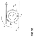
このため、図3Bには、図3Aに示した車両の複数の車輪4のうちの1つの概略断面図が示されている。 Therefore, FIG. 3B shows a schematic cross-sectional view of one of the plurality of wheels 4 of the vehicle shown in FIG. 3A.
図3Bに示したように、車輪4のタイヤ2は、トレッドデプスtpを有しかつ破線で略示したトレッド1を有する。車輪4の内径はr0であり、車輪4の内径r0は、車輪中心7と、トレッド1のタイヤ側の始端部8との間の間隔である。したがって車輪4の内径r0は、タイヤ2のトレッド1を含まない車輪4の半径を表しているのである。さらに図3Bでは車輪4の転がり方向が矢印Aによって略示されている。
As shown in FIG. 3B, the tire 2 of the wheel 4 has a
図3Bにはさらに、タイヤ2内に配置されている車輪ユニット17が示されている。このようなタイヤユニットないしは車輪ユニット17がタイヤ接地面に、すなわち路面48とタイヤ2との接触面に、ないしは摺動面の内側に取り付けられる場合、このタイヤユニットは、例えば加速度センサ、衝撃センサまたは圧電素子を介して、さらに路面48とタイヤ2との間の相互作用を直接検出することができる。この場合には、タイヤ空気圧測定、場合によっては行われるタイヤ温度測定および速度測定に関連して、タイヤ接地長さ測定により、個別のタイヤ負荷を求めることができる。すなわち、このタイヤ負荷は、タイヤ接地面長さ、タイヤ空気圧、温度および速度の関数なのである。
FIG. 3B further shows a
以下に詳しく説明するように、図3Bに詳しく示していない車輪ユニット17の複数のセンサにより、また別に求めた複数のパラメタに基づき、この車両の動作中にタイヤ2のトレッド1の瞬時トレッドデプスを求めることができる。この瞬時トレッドデプスの値を求める際には、すでに説明したように、車両の車輪と同等の剛体車輪を仮定することから出発する。
As will be described in detail below, the instantaneous tread depth of the
上記に加えて図4には、図4に詳しく示していない車両のタイヤのトレッドのトレッドデプスを求めるためのシステム16が示されている。図3Aおよび3Bと同じ機能を有するコンポーネントは、同じ参照符号で示されており、以下では再度説明しない。 In addition to the above, FIG. 4 shows a system 16 for determining the tread depth of a vehicle tire tread not shown in detail in FIG. Components having the same functions as in FIGS. 3A and 3B are indicated with the same reference numerals and will not be described again below.
システム16は、1つの制御装置11を有しており、また車両の車輪ないしはタイヤ毎に車輪ユニット17を有している。図4では見易くするため、このような車輪ユニット17が1つだけ示されている。
The system 16 has one
車輪ユニット17は、各タイヤに配置することができ、また図示の実施形態では、瞬時タイヤ温度を求めるための温度センサ18と、瞬時タイヤ空気圧を求めるための圧力センサ19と、瞬時タイヤ負荷を求めるためのタイヤ負荷センサ20とを1つずつ有する。さらに車輪ユニット17は、記憶装置27を有しており、記憶装置27には、例えば、タイヤのタイプおよび/またはタイヤの製造後経過年数についてのデータを格納することができる。殊に特徴的なタイヤ特性、例えばタイヤタイプ、製造後経過年数、サイズ、DOTナンバおよびトレッドウェア値なども格納して利用することできる。さらに車輪ユニット17は、送信装置28を有しており、この装置を用いて上記のデータを制御装置11に伝送することできる。
The
制御装置11はこのために受信装置12を有しており、この受信装置は、送信装置28から瞬時タイヤ温度と、瞬時タイヤ空気圧値と、瞬時タイヤ負荷値とを受信するように構成されている。
The
さらに受信装置12は、車両の、タイヤを装着した車輪の瞬時回転速度値を受信するように構成されている。このために受信装置12は、信号線路47を介して制御装置31に接続されている。この制御装置31は、図示した実施形態においてABSまたはESP制御装置として構成されている。制御装置31はさらに信号線路32を介して、回転角センサの形態の第1センサ5に接続されている。ここでは車両の各車輪に専用の第1センサ5が割り当てられているが、図4では見易くするため、このような第1センサ5が1つだけ示されている。
Furthermore, the receiving device 12 is configured to receive an instantaneous rotation speed value of a vehicle wheel equipped with a tire. For this purpose, the receiving device 12 is connected to the control device 31 via a signal line 47. The control device 31 is configured as an ABS or ESP control device in the illustrated embodiment. The control device 31 is further connected via a
さらに制御装置31は、信号線路33を介して加速度センサ21に接続されており、この加速度センサ21は、車両の長手方向加速度と、車両の横方向加速度と検出するように構成されている。さらに制御装置31は信号線路34を介してヨーレートセンサ22に、また信号線路35を介して操舵角センサ23に接続されている。さらに制御装置31は信号線路36を介してセンサ24に接続されており、このセンサは、車両の詳しく図示していない制動装置の動作状態を求めるように構成されている。例えばセンサ24は、この制動装置の制動ランプ信号を制御装置31に伝送することができる。上で挙げた複数のセンサによって求めたデータは制御装置31で処理され、これによって求められた複数の値は、受信装置12に伝送される。
Further, the control device 31 is connected to the acceleration sensor 21 via the
受信装置12はさらに、信号線路37を介してナビゲーションシステム25に接続されている。このナビゲーションシステムは、位置検出センサの形態の第2センサ6を有する。第2センサ6によって求めたデータに基づき、ナビゲーションシステム25によって車両の瞬時速度を求め、受信装置12を用いてこの瞬時速度を制御装置11に供給することができる。
The receiving device 12 is further connected to the
さらに受信装置12は、信号線路38を介して、車両の詳しく図示していない駆動原動機の原動機制御装置26に接続されている。これによって駆動原動機の瞬時回転トルクを制御装置11に伝送することができる。
Furthermore, the receiving device 12 is connected to a prime
制御装置11はさらに第1算出装置13を有しており、この第1算出装置は、受信装置12によって受信した瞬時回転速度値と、受信した瞬時速度値とに基づいて、タイヤを装着した車輪の瞬時の動的な半径を算出するように構成されている。このために第1算出装置13は、信号線路39を介して受信装置12に接続されている。
The
さらに制御装置11は第2算出装置14を有しており、この第2算出装置は、受信した瞬時タイヤ温度値と、受信した瞬時タイヤ空気圧値と、受信した瞬時タイヤ負荷値と、タイヤのタイプおよび/またはタイヤの製造後経過年数とに基づいて、車輪の瞬時の動的な内径を求めるように構成されている。タイヤの製造後経過年数は、例えば記憶装置27に格納されている製造データに基づいて求めることができ、これによって殊に、新品のタイヤであるか否かを識別することができ、新しい場合にはシステム16はこのタイヤを読み込むことできる。
Further, the
第2算出装置14は、信号線路40を介して受信装置12に接続されており、また図示の実施形態では、記憶装置9に格納されている複数の特性曲線を用いて、車輪の瞬時の動的な内径を求めるように構成されている。記憶装置9はこのため、信号線路43を介して第2算出装置14に接続されている。
The second calculation device 14 is connected to the reception device 12 via the
制御装置11はさらに第3算出装置15を有しており、この第3算出装置は、求めた瞬時の動的な半径および求めた瞬時の動的な内径に基づいて、タイヤのトレッドのトレッドデプスを求めるように構成されている。このために第3算出装置15は信号線路41を介して第1算出装置13に、または信号線路42を介して第2算出装置14に接続されている。
The
図示の実施形態では、受信装置12によって受信した車両の瞬時加速度の値と、車両の瞬時ヨーレートの値と、瞬時操舵角と、駆動原動機の瞬時回転トルクと、制動装置の動作状態とに基づいて、スリップが発生していない、ないしは、可能な限りに小さいスリップしか発生しておらず、かつ、車両が実質的に直線的に走行している走行状況を都度の瞬時走行状況が表しているか否かを求めるように第3算出装置15が構成されている。 In the illustrated embodiment, based on the instantaneous acceleration value of the vehicle, the instantaneous yaw rate value of the vehicle, the instantaneous steering angle, the instantaneous rotational torque of the driving engine, and the operating state of the braking device received by the receiving device 12. Whether or not the slip is not generated, or the slip that is as small as possible is generated, and whether or not the instantaneous traveling state represents the traveling state in which the vehicle is traveling substantially linearly The third calculation device 15 is configured to obtain the above.
スリップが発生していない、ないしは、可能な限りに小さいスリップしか発生しておらず、かつ、車両が実質的に直線的に走行する走行状況を、上記の瞬時の走行状況が表していないことが第3算出装置15によって求められた場合、この情報は第1算出装置13および/または第2算出装置14に伝送することができ、この状況において上記の瞬時の動的な半径ないしは瞬時の動的な内径は算出されなくなる。このため、殊に信号線路41および42は双方向信号線路として構成されている。さらに、このような状況において、すでに求められた値は、トレッドデプスを求める際に考慮されないままになり得る。 The above-mentioned instantaneous running situation does not represent a running situation in which no slip occurs or only the smallest possible slip occurs and the vehicle runs substantially linearly. If determined by the third calculation device 15, this information can be transmitted to the first calculation device 13 and / or the second calculation device 14, in this situation the instantaneous dynamic radius or the instantaneous dynamic The inner diameter is not calculated. For this reason, in particular, the signal lines 41 and 42 are configured as bidirectional signal lines. Further, in such a situation, the already determined value may remain unconsidered when determining the tread depth.
さらに、図示の実施形態において第3算出装置15は、タイヤのトレッドのトレッドデプスが、あらかじめ設定した閾値を下回るか否かを求めるように構成されている。下回った場合、車両の出力装置30を用いて警告メッセージを出力することができ、また送信装置29を用いて別の車両にこれを通知することができる。第3算出装置15はこのために信号線路45を介して出力装置30に、また信号線路44を介して送信装置29に接続されている。
Furthermore, in the illustrated embodiment, the third calculation device 15 is configured to determine whether the tread depth of the tire tread is below a preset threshold value. If it falls below, a warning message can be output using the
さらにタイヤのトレッドの求めたトレッドデプスは、車両のドライバアシストシステム10に伝送することができる。このために第3算出装置15は、信号線路46を介して、ブレーキアシストまたは非常時制動システムとして構成されているドライバアシストシステム10に接続されている。
Further, the tread depth obtained from the tire tread can be transmitted to the driver assist system 10 of the vehicle. For this purpose, the third calculation device 15 is connected via a
タイヤのトレッドデプスは、車両の挙動に大きな影響を有する。このことは、殊にクリティカルな走行状況において当てはまる。タイヤと路面との間の最大グリップは一方では、都度の路面状況に大きく依存し、例えば路面状態または路面上にある雪または氷に大きく依存する。都度の状況に対するグリップは他方では、所定のタイヤ特性によって最適化することができる。このうちの一つが、殊に都度の気象状況に最適化されたタイヤトレッドである。タイヤトレッドの有効性は、トレッドデプスによって大きく左右される。例えば、ハイドロプレーニングの際、路面とタイヤとの間の水は、十分ではなくなってしまったトレッドによってはもはや排水できないのである。 The tread depth of the tire has a great influence on the behavior of the vehicle. This is especially true in critical driving situations. On the one hand, the maximum grip between the tire and the road surface is highly dependent on the respective road surface conditions, for example on the road surface condition or on snow or ice on the road surface. On the other hand, the grip for each situation can be optimized by means of predetermined tire characteristics. One of these is a tire tread that is optimized especially for each weather situation. The effectiveness of a tire tread depends greatly on the tread depth. For example, during hydroplaning, the water between the road surface and the tires can no longer be drained by a tread that is no longer sufficient.
十分なトレッドデプスにより、殊にクリティカルな走行状況におけるタイヤと路面との間の最大限に可能なグリップを保証することができる。このために一般的には、季節によって変化し得る最小トレッドデプスに対する法的な要求が存在するのである。 A sufficient tread depth can guarantee the maximum possible grip between the tire and the road surface, especially in critical driving situations. For this reason, there is generally a legal requirement for a minimum tread depth that can vary from season to season.
本発明によって有利にも、走行中のトレッドデプスを推定ないしは求めることができる方法、制御装置およびシステムが得られる。上記の情報は、殊にドライバに提供可能であり、これによってドライバは、トレッドデプスが小さくなりすぎたタイヤを適時に交換するのである。これにより、殊にハイドロプレーニングおよび雪に覆われた路面におけるグリップの消失のような特定の危険状況およびこれに伴う事故を回避することができる。 The present invention advantageously provides a method, control device and system that can estimate or determine the tread depth during travel. The above information can be provided to the driver, in particular, so that the driver can replace tires whose tread depth has become too small in a timely manner. This makes it possible to avoid certain dangerous situations and associated accidents, such as loss of grip, especially on hydroplaning and snowy road surfaces.
さらに上記の求めたトレッドデプスは、別の車両システムに、殊にアクティブセーフティシステムに、例えばABSまたはESPに供給することができる。これにより、関連する制御ストラテジをグリップ低下状況に適合させて最適化することができる。 Furthermore, the tread depth determined above can be supplied to another vehicle system, in particular to an active safety system, for example ABS or ESP. Thereby, the related control strategy can be optimized by adapting to the grip reduction situation.
さらにトレッドデプスの中期的な経過により、季節によって決まるタイヤ交換について推定を行うことができる。これにより、該当するタイヤが、到来するシーズンに対してまだ十分なトレッドを有するかまたは交換すべきかを推定することができるのである。 In addition, with the medium-term progress of the tread depth, it is possible to estimate the tire replacement determined by the season. This makes it possible to estimate whether the tire in question still has enough tread for the coming season or should be replaced.
1 トレッド、 2 タイヤ、 3 車両、 4 車輪、 5 センサ、 6 センサ、 7 車輪中心、 8 始端部、 9 記憶装置、 10 ドライバアシストシステム、 11 制御装置、 12 受信装置、 13 算出装置、 14 算出装置、 15 算出装置、 16 システム、 17 車輪ユニット、 18 温度センサ、 19 圧力センサ、 20 タイヤ負荷センサ、 21 加速度センサ、 22 ヨーレートセンサ、 23 操舵角センサ、 24 センサ、 25 ナビゲーションシステム、 26 原動機制御装置、 27 記憶装置、 28 送信装置、 29 送信装置、 30 出力装置、 31 制御装置、 32 信号線路、 33 信号線路、 34 信号線路、 35 信号線路、 36 信号線路、 37 信号線路、 38 信号線路、 39 信号線路、 40 信号線路、 41 信号線路、 42 信号線路、 43 信号線路、 44 信号線路、 45 信号線路、 46 信号線路、 47 信号線路、 48 路面、 50 ステップ、 60 ステップ、 70 ステップ、 80 ステップ、 90 ステップ、 100 ステップ、 110 ステップ、 120 ステップ、 130 ステップ、 140 ステップ、 150 ステップ、 A 矢印 1 Tread, 2 Tire, 3 Vehicle, 4 Wheel , 5 Sensor, 6 Sensor, 7 Wheel Center, 8 Start End, 9 Storage Device, 10 Driver Assist System, 11 Control Device, 12 Receiving Device, 13 Calculation Device, 14 Calculation Device , 15 calculation device, 16 system, 17 wheel unit, 18 temperature sensor, 19 pressure sensor, 20 tire load sensor, 21 acceleration sensor, 22 yaw rate sensor, 23 steering angle sensor, 24 sensor, 25 navigation system, 26 prime mover control device, 27 storage device, 28 transmission device, 29 transmission device, 30 output device, 31 control device, 32 signal line, 33 signal line, 34 signal line, 35 signal line, 36 signal line, 37 signal line, 38 signal line, 39 signal Line, 40 signal line, 41 signal line, 42 signal Line, 43 signal line, 44 signal line, 45 signal line, 46 signal line, 47 signal line, 48 road surface, 50 steps, 60 steps, 70 steps, 80 steps, 90 steps, 100 steps, 110 steps, 120 steps, 130 Step, 140 step, 150 step, A arrow
Claims (12)
当該方法は、
・ 少なくとも1つの第1センサ(5)によって求めたデータに基づいて、前記タイヤ(2)を装着した前記車両(3)の車輪(4)の瞬時回転速度を求めるステップと、
・ 前記少なくとも1つの第1センサ(5)とは異なる少なくとも1つの第2センサ(6)によって求めたデータに基づいて、前記車両(3)の瞬時速度を求めるステップと、
・ 求めた前記瞬時回転速度および求めた前記瞬時速度に基づいて、前記タイヤ(2)を装着した前記車輪(4)の瞬時の動的な半径を求めるステップと、
・ 瞬時タイヤ温度、瞬時タイヤ空気圧および瞬時タイヤ負荷からなるグループから選択される、前記タイヤ(2)の少なくとも1つの第1パラメタを求めるステップと、
・ 求めた前記少なくとも1つの第1パラメタに基づいて、前記車輪(4)の瞬時の動的な内径を求めるステップとを有しており、前記車輪(4)の前記内径は、車輪中心(7)と、前記トレッド(1)のタイヤ側の始端部(8)との間の間隔であり、
前記方法はさらに、
・ 求めた前記瞬時の動的な半径と、求めた前記瞬時の動的な内径とに基づいて前記タイヤ(2)の前記トレッド(1)のトレッドデプスを求めるステップを有する、
ことを特徴とする方法。 In a method for determining the tread depth of the tread (1) of the tire (2) during operation of the vehicle (3) having the tire (2),
The method is
Obtaining an instantaneous rotational speed of a wheel (4) of the vehicle (3) on which the tire (2) is mounted based on data obtained by at least one first sensor (5);
Obtaining an instantaneous speed of the vehicle (3) based on data obtained by at least one second sensor (6) different from the at least one first sensor (5);
Obtaining an instantaneous dynamic radius of the wheel (4) fitted with the tire (2) based on the determined instantaneous rotational speed and the determined instantaneous speed;
Determining at least one first parameter of the tire (2) selected from the group consisting of instantaneous tire temperature, instantaneous tire pressure and instantaneous tire load;
- obtained based on the at least one first parameter has the step of obtaining the dynamic internal diameter of instantaneous of the wheel (4), the inner diameter of the wheel (4) the wheel center (7 ) And the tire end side end (8) of the tread (1),
The method further includes:
A step of obtaining a tread depth of the tread (1) of the tire (2) based on the obtained instantaneous dynamic radius and the obtained instantaneous dynamic inner diameter;
A method characterized by that.
前記少なくとも1つの第1センサ(5)は、回転数センサとして構成されている、
ことを特徴とする方法。 The method of claim 1, wherein
The at least one first sensor (5) is configured as a rotational speed sensor;
A method characterized by that.
前記少なくとも1つの第2センサ(6)は、衛星支援位置検出センサと、レーダセンサと、ライダセンサと、超音波センサと、光学式カメラとからなるグループから選択される、
ことを特徴とする方法。 The method according to claim 1 or 2, wherein
The at least one second sensor (6) is selected from the group consisting of a satellite assisted position detection sensor, a radar sensor, a lidar sensor, an ultrasonic sensor, and an optical camera.
A method characterized by that.
前記車輪(4)の前記瞬時の動的な内径を求めるステップはさらに、求めた前記瞬時速度に基づいて行われる、
ことを特徴とする方法。 The method according to any one of claims 1 to 3, wherein
The step of determining the instantaneous dynamic inner diameter of the wheel (4) is further performed based on the determined instantaneous speed.
A method characterized by that.
前記車輪(4)の前記瞬時の動的な内径を求めるステップはさらに、前記タイヤ(2)のタイプおよび/または製造後経過年数に基づいて行われる、
ことを特徴とする方法。 The method according to any one of claims 1 to 4, wherein
The step of determining the instantaneous dynamic inner diameter of the wheel (4) is further performed based on the type of tire (2) and / or the years since manufacture.
A method characterized by that.
前記車輪(4)の前記瞬時の動的な内径を求めるステップは、記憶装置(9)に格納された少なくとも1つの特性曲線を用いて行われる、
ことを特徴とする方法。 The method according to any one of claims 1 to 5, wherein
The step of determining the instantaneous dynamic inner diameter of the wheel (4) is performed using at least one characteristic curve stored in a storage device (9).
A method characterized by that.
さらに、前記車両(3)の瞬時加速度と、前記車両(3)の瞬時ヨーレートと、瞬時操舵角と、前記車両(3)の駆動原動機の瞬時回転トルクと、前記車両(3)の制動装置の動作状態とからなるグループから選択される少なくとも1つの第2パラメタを求め、
前記タイヤ(2)の前記トレッドのトレッドデプスを求める前記ステップを、さらに、求めた前記少なくとも1つの第2パラメタに依存して行う、
ことを特徴とする方法。 The method according to any one of claims 1 to 6, wherein
Further, the instantaneous acceleration of the vehicle (3), the instantaneous yaw rate of the vehicle (3), the instantaneous steering angle, the instantaneous rotational torque of the driving motor of the vehicle (3), and the braking device of the vehicle (3) Determining at least one second parameter selected from the group consisting of operating states;
The step of determining the tread depth of the tread of the tire (2) is further performed depending on the determined at least one second parameter;
A method characterized by that.
さらに、前記タイヤ(2)の前記トレッドの求めた前記トレッドデプスが、あらかじめ設定した第1閾値を下回る場合、警告メッセージを出力する、
ことを特徴とする方法。 The method according to any one of claims 1 to 7, wherein
Furthermore, a warning message is output when the tread depth obtained by the tread of the tire (2) is below a first threshold value set in advance.
A method characterized by that.
さらに、前記タイヤ(2)の前記トレッドの求めた前記トレッドデプスが、あらかじめ設定した第2閾値を下回る場合、サービス施設への通知を行う、
ことを特徴とする方法。 The method according to any one of claims 1 to 8, wherein
Furthermore, when the tread depth obtained by the tread of the tire (2) is lower than a preset second threshold value, a notification to a service facility is performed.
A method characterized by that.
前記車両(3)の少なくとも1つのドライバアシストシステム(10)に前記タイヤ(2)の前記トレッドの求めた前記トレッドデプスを伝送する、
ことを特徴とする方法。 10. The method according to any one of claims 1 to 9, wherein
Transmitting the tread depth determined by the tread of the tire (2) to at least one driver assist system (10) of the vehicle (3);
A method characterized by that.
該制御装置は、少なくとも1つの受信装置(12)と、第1算出装置(13)と、第2算出装置(14)と、第3算出装置(15)とを有しており、
前記受信装置(12)は、
前記車両(3)の、前記タイヤ(2)を装着した車輪(4)の瞬時回転速度、
前記車両(3)の瞬時速度、ならびに、
瞬時タイヤ温度と、瞬時タイヤ空気圧と、瞬時タイヤ負荷とからなるグループから選択される前記タイヤ(2)の少なくとも1つの第1パラメタ
を受信するように構成されており、
前記第1算出装置(13)は、受信した前記瞬時回転速度と、受信した前記瞬時速度とに基づいて、前記タイヤ(2)を装着した前記車輪(4)の瞬時の動的な半径を求めるように構成されており、
前記第2算出装置(14)は、受信した前記少なくとも1つの第1パラメタに基づいて、前記車輪(4)の瞬時の動的な内径を求めるように構成されており、前記車輪(4)の前記内径は、車輪中心(7)と、前記トレッド(1)のタイヤ側の始端部(8)との間の間隔であり、
前記第3算出装置(15)は、求めた前記瞬時の動的な半径と、求めた前記瞬時の動的の内径とに基づいて、前記タイヤ(2)の前記トレッド(1)のトレッドデプスを求めるように構成されている、
ことを特徴とする制御装置。 In the control device for the vehicle (3) for determining the tread depth of the tread (1) of the tire (2) of the vehicle (3),
The control device includes at least one receiving device (12), a first calculating device (13), a second calculating device (14), and a third calculating device (15),
The receiving device (12)
Instantaneous rotational speed of the wheel (4) of the vehicle (3) on which the tire (2) is mounted;
The instantaneous speed of the vehicle (3), and
Configured to receive at least one first parameter of the tire (2) selected from the group consisting of instantaneous tire temperature, instantaneous tire pressure, and instantaneous tire load;
The first calculation device (13) obtains an instantaneous dynamic radius of the wheel (4) on which the tire (2) is mounted based on the received instantaneous rotational speed and the received instantaneous speed. Is configured as
The second calculation device (14) is configured to obtain an instantaneous dynamic inner diameter of the wheel (4) based on the received at least one first parameter, and the wheel (4) The inner diameter is a distance between a wheel center (7) and a tire-side start end (8) of the tread (1),
The third calculation device (15) calculates the tread depth of the tread (1) of the tire (2) based on the obtained instantaneous dynamic radius and the obtained dynamic inner diameter. Configured to ask for,
A control device characterized by that.
該システムは、請求項11に記載の制御装置(11)と、少なくとも1つの車輪ユニット(17)とを有しており、
当該少なくとも1つの車輪ユニット(17)は、前記タイヤ(2)に配置可能であり、かつ、温度センサ(18)と、圧力センサ(19)と、タイヤ負荷センサ(20)とからなるグループから選択される少なくとも1つのセンサを有している、
ことを特徴とするシステム。 In a system for a vehicle (3) for determining a tread depth of a tread (1) of a tire (2) of a vehicle (3),
The system comprises a control device (11) according to claim 11 and at least one wheel unit (17),
The at least one wheel unit (17) can be arranged on the tire (2) and is selected from the group consisting of a temperature sensor (18), a pressure sensor (19), and a tire load sensor (20). Having at least one sensor
A system characterized by that.
Applications Claiming Priority (3)
| Application Number | Priority Date | Filing Date | Title |
|---|---|---|---|
| DE102012217901.1 | 2012-10-01 | ||
| DE102012217901.1A DE102012217901B3 (en) | 2012-10-01 | 2012-10-01 | Method, controller and system for determining a tread depth of a tread of a tire |
| PCT/EP2013/069434 WO2014053322A1 (en) | 2012-10-01 | 2013-09-19 | Method, control device and system for determining a profile depth of a profile of a tyre |
Publications (2)
| Publication Number | Publication Date |
|---|---|
| JP2015530955A JP2015530955A (en) | 2015-10-29 |
| JP6045702B2 true JP6045702B2 (en) | 2016-12-14 |
Family
ID=49274609
Family Applications (1)
| Application Number | Title | Priority Date | Filing Date |
|---|---|---|---|
| JP2015527942A Active JP6045702B2 (en) | 2012-10-01 | 2013-09-19 | Method, control device and system for determining tread depth of tire tread |
Country Status (7)
| Country | Link |
|---|---|
| US (1) | US9669664B2 (en) |
| EP (1) | EP2867036B1 (en) |
| JP (1) | JP6045702B2 (en) |
| KR (1) | KR101675586B1 (en) |
| CN (1) | CN104781092B (en) |
| DE (1) | DE102012217901B3 (en) |
| WO (1) | WO2014053322A1 (en) |
Families Citing this family (44)
| Publication number | Priority date | Publication date | Assignee | Title |
|---|---|---|---|---|
| DE102013208190B4 (en) | 2013-05-03 | 2024-03-07 | Bayerische Motoren Werke Aktiengesellschaft | Method for monitoring tire wear on a motor vehicle |
| US9921134B2 (en) | 2014-08-04 | 2018-03-20 | Dr. Ing. H.C. F. Porsche Aktiengesellschaft | System and method for determining tire wear |
| EP2982521B1 (en) * | 2014-08-04 | 2017-07-19 | Dr. Ing. h.c. F. Porsche AG | System and method for determining tire wear properties |
| GB2531746A (en) * | 2014-10-28 | 2016-05-04 | Pre-Chasm Res Ltd | Tyre tread monitoring |
| US20160161373A1 (en) * | 2014-12-03 | 2016-06-09 | The Goodyear Tire & Rubber Company | Tire lift-off propensity predictive system and method |
| US9963146B2 (en) | 2014-12-03 | 2018-05-08 | The Goodyear Tire & Rubber Company | Tire lift-off propensity predictive system and method |
| US9719886B2 (en) | 2015-07-21 | 2017-08-01 | The Goodyear Tire & Rubber Company | Tread wear estimation system and method |
| US9921133B2 (en) * | 2015-07-29 | 2018-03-20 | Hon Hai Precision Industry Co., Ltd. | Tread depth measuring system |
| DE102015216212A1 (en) * | 2015-08-25 | 2017-03-02 | Continental Reifen Deutschland Gmbh | Method for determining a tread depth of a tire profile, and control device therefor |
| US10464419B2 (en) | 2015-09-30 | 2019-11-05 | Cnh Industrial America Llc | System and method for automatically controlling vehicle speed based on track-related temperatures of a work vehicle |
| FR3042281B1 (en) | 2015-10-13 | 2017-10-27 | Continental Automotive France | METHOD FOR DETERMINING THE RADIAL ACCELERATION OF THE WHEEL OF A VEHICLE |
| DE102015220097A1 (en) | 2015-10-15 | 2017-04-20 | Continental Automotive Gmbh | Method and device for determining a vehicle speed of a vehicle |
| US9821611B2 (en) | 2015-10-21 | 2017-11-21 | The Goodyear Tire & Rubber Company | Indirect tire wear state estimation system |
| EP3376205B1 (en) * | 2015-11-10 | 2020-12-30 | Bridgestone Corporation | Tire managing method and tire managing apparatus |
| TWI585382B (en) | 2016-03-02 | 2017-06-01 | 緯創資通股份有限公司 | Method, system, and computer-readable medium for detecting depth of tire tread pattern |
| FR3053004B1 (en) | 2016-06-23 | 2018-06-22 | Compagnie Generale Des Etablissements Michelin | METHOD FOR DETECTING A MODIFICATION OF THE BEARING RAY OF A TIRE, AND ASSOCIATED FOLLOWING |
| CN107554206B (en) * | 2017-02-13 | 2019-06-04 | 徐州金茂源车业有限公司 | A kind of wheel footpath regulating system for electric vehicle |
| DE102017204648A1 (en) | 2017-03-21 | 2018-09-27 | Continental Automotive Gmbh | Method, control device and system for determining a tread depth of a profile of a tire |
| US20180290501A1 (en) * | 2017-04-07 | 2018-10-11 | GM Global Technology Operations LLC | Methods and apparatus for determining remaining life of a tire based on road vibration data and tire tread groove depth |
| CN107727042A (en) * | 2017-09-28 | 2018-02-23 | 网伦天下(北京)智能科技有限公司 | The pattern depth calculating system and device of a kind of tire |
| DE102017221142B4 (en) | 2017-11-27 | 2019-12-19 | Continental Automotive Gmbh | Method, control device and system for determining a tread depth of a tread profile |
| US10518590B2 (en) * | 2018-03-05 | 2019-12-31 | Sensata Technologies, Inc. | System and method for tracking tire tread wear |
| CN110239561B (en) * | 2018-03-07 | 2022-08-05 | 奥迪股份公司 | Driving assistance system and method |
| CN108790619A (en) * | 2018-05-14 | 2018-11-13 | 山东玲珑轮胎股份有限公司 | Automatic alarm system for tire pattern depth |
| US10960712B2 (en) * | 2018-06-28 | 2021-03-30 | Nissan North America, Inc. | Tire wear estimation using a hybrid machine learning system and method |
| CN109249934A (en) * | 2018-09-30 | 2019-01-22 | 广州小鹏汽车科技有限公司 | A kind of tire wear calculation method of parameters, system and device |
| DE102018008638A1 (en) * | 2018-11-02 | 2020-05-07 | Domenic Schick | Automatic tire wear indicator in the motor vehicle, the driver of a vehicle receives a message if e.g. a tire has worn so far that it will be necessary to change tires in the near future |
| US11644386B2 (en) | 2018-12-11 | 2023-05-09 | The Goodyear Tire & Rubber Company | Tire wear state estimation system and method |
| DE102018221981B4 (en) | 2018-12-17 | 2020-10-01 | Continental Automotive Gmbh | Method, control device and system for determining tread depths of tires on vehicles |
| JP7194066B2 (en) | 2019-03-29 | 2022-12-21 | Toyo Tire株式会社 | Calculation model generation system, wear amount estimation system, and calculation model generation method |
| AU2020220054A1 (en) | 2019-08-30 | 2021-03-18 | The Goodyear Tire & Rubber Company | Tire wear state estimation system and method employing footprint length |
| AU2020220060A1 (en) | 2019-08-30 | 2021-03-18 | The Goodyear Tire & Rubber Company | Method for extracting changes in tyre characteristics |
| US11981163B2 (en) | 2019-08-30 | 2024-05-14 | The Goodyear Tire & Rubber Company | Tire wear state estimation system and method employing footprint shape factor |
| US11480434B2 (en) * | 2020-02-04 | 2022-10-25 | Pony Ai Inc. | Initial localization |
| KR20220153026A (en) * | 2020-03-06 | 2022-11-17 | 택타일 모빌리티 엘티디. | vehicle monitoring |
| US11650134B2 (en) * | 2020-03-25 | 2023-05-16 | Sensata Technologies, Inc. | Determining tread depth using data from a tire-mounted sensor |
| DE102020118041A1 (en) | 2020-07-08 | 2022-01-13 | Valeo Schalter Und Sensoren Gmbh | Method for determining or estimating the actual tire size of a motor vehicle tire using a mathematical model, computer program, computer-readable storage medium and assistance system |
| DE102020121769A1 (en) | 2020-08-19 | 2022-02-24 | Valeo Schalter Und Sensoren Gmbh | Determination of a wheel circumference for a wheel of a motor vehicle |
| US20240025214A1 (en) * | 2020-09-25 | 2024-01-25 | Sensata Technologies, Inc. | Adjustment of indirectly determined values of a tire monitoring system |
| WO2022191875A1 (en) * | 2021-03-12 | 2022-09-15 | Bridgestone Americas Tire Operations, Llc | System and method for estimation of tread depth from tire pressure and/or temperature measurements |
| DE102021108978A1 (en) | 2021-04-12 | 2022-10-13 | Audi Aktiengesellschaft | Method for determining the state of wear of a tire on a motor vehicle |
| US20230011981A1 (en) * | 2021-07-08 | 2023-01-12 | Volvo Car Corporation | Real-time tire monitoring system |
| DE102022204695A1 (en) | 2022-05-13 | 2023-11-16 | Continental Automotive Technologies GmbH | Method, control device and system for determining the tread depth of a tire |
| FR3139753A1 (en) | 2022-09-15 | 2024-03-22 | Continental Automotive Technologies | Method for determining a compensated dynamic radius of a wheel of a vehicle, method for estimating the depth of a tread of a tire and motor vehicle for implementing said methods |
Family Cites Families (19)
| Publication number | Priority date | Publication date | Assignee | Title |
|---|---|---|---|---|
| JP3289375B2 (en) * | 1993-03-24 | 2002-06-04 | 株式会社デンソー | VEHICLE VEHICLE VEHICLE ESTIMATION DEVICE AND TIRE CONDITION DETECTOR USING ESTIMATED VEHICLE VEHICLE VEHICLE |
| JPH07164830A (en) * | 1993-12-14 | 1995-06-27 | Matsushita Electric Ind Co Ltd | Tire abrasion alarm device |
| DE19716586C1 (en) | 1997-04-21 | 1998-08-06 | Continental Ag | Tyre wear measuring method for moving vehicle |
| US6313742B1 (en) | 2000-08-09 | 2001-11-06 | International Truck & Engine Corp | Method and apparatus for wheel condition and load position sensing |
| DE10218781A1 (en) * | 2002-04-26 | 2003-11-13 | Tuev Automotive Gmbh | Pneumatic tire mountable on a rim, sensor network, revolution measuring unit and vehicle monitoring system |
| DE10304126A1 (en) * | 2003-02-03 | 2004-08-05 | Odt-Gmbh | Measurement of tire pressure, tire pressure loss and tire profile by comparison of ABS derived velocity and distance traveled with reference velocity and distance traveled measurements |
| DE10306498A1 (en) * | 2003-02-17 | 2004-08-26 | Bayerische Motoren Werke Ag | Automatic vehicle tire monitor, to determine the wear on the running tread profile, has sensors at the wheels linked to an evaluation unit which is also connected to a satellite position signal receiver |
| JP2006162384A (en) * | 2004-12-06 | 2006-06-22 | Hitachi Ltd | Worn tire warning device |
| DE102004060402A1 (en) | 2004-12-14 | 2006-07-13 | Adc Automotive Distance Control Systems Gmbh | Method and device for determining a vehicle speed |
| DE102005052476A1 (en) * | 2005-11-03 | 2007-05-10 | Continental Aktiengesellschaft | Method for individually estimating the actual and average wear of a vehicle tire comprises measuring the wear on the tire and emitting an acoustic and/or visual signal when the required level of maximum performance of the tire is reached |
| BRPI0620675A2 (en) * | 2005-12-15 | 2011-11-22 | Goodyear Tire & Rubber | method of determining vehicle properties |
| US8493200B2 (en) | 2006-12-13 | 2013-07-23 | Kabushiki Kaisha Bridgestone | Apparatus for estimating tire wear amount and a vehicle on which the apparatus for estimating tire wear is mounted |
| JP2008143460A (en) * | 2006-12-13 | 2008-06-26 | Bridgestone Corp | Tire wear loss estimating device and vehicle mounted therewith |
| JP2008247126A (en) | 2007-03-29 | 2008-10-16 | Sumitomo Rubber Ind Ltd | Tire wear warning method |
| DE102008006566A1 (en) * | 2008-01-29 | 2009-07-30 | Robert Bosch Gmbh | Method for determining a vehicle tire tread depth |
| DE102008045619A1 (en) | 2008-09-03 | 2010-03-04 | Daimler Ag | To determine the speed/direction of a moving vehicle, a downward camera is integrated into a wing mirror for an image processor to compare images from different time points |
| IT1393071B1 (en) * | 2008-10-24 | 2012-04-11 | Pirelli | METHOD AND SYSTEM FOR WEAR TESTING OF THE VEHICLE TIRES |
| DE102009006458A1 (en) * | 2009-01-28 | 2010-08-05 | Continental Automotive Gmbh | Device and method for measuring the tread depth of a motor vehicle tire |
| DE102010016551B4 (en) * | 2010-04-21 | 2019-02-28 | Continental Reifen Deutschland Gmbh | A method of monitoring or measuring tread depth in a vehicle tire having a tire module |
-
2012
- 2012-10-01 DE DE102012217901.1A patent/DE102012217901B3/en not_active Expired - Fee Related
-
2013
- 2013-09-19 KR KR1020157004491A patent/KR101675586B1/en active IP Right Grant
- 2013-09-19 EP EP13770859.0A patent/EP2867036B1/en active Active
- 2013-09-19 CN CN201380044249.6A patent/CN104781092B/en active Active
- 2013-09-19 US US14/423,189 patent/US9669664B2/en active Active
- 2013-09-19 JP JP2015527942A patent/JP6045702B2/en active Active
- 2013-09-19 WO PCT/EP2013/069434 patent/WO2014053322A1/en active Application Filing
Also Published As
| Publication number | Publication date |
|---|---|
| WO2014053322A1 (en) | 2014-04-10 |
| CN104781092A (en) | 2015-07-15 |
| JP2015530955A (en) | 2015-10-29 |
| DE102012217901B3 (en) | 2014-05-28 |
| EP2867036A1 (en) | 2015-05-06 |
| EP2867036B1 (en) | 2016-06-22 |
| KR20150038211A (en) | 2015-04-08 |
| US20150239298A1 (en) | 2015-08-27 |
| CN104781092B (en) | 2017-03-01 |
| US9669664B2 (en) | 2017-06-06 |
| KR101675586B1 (en) | 2016-11-11 |
Similar Documents
| Publication | Publication Date | Title |
|---|---|---|
| JP6045702B2 (en) | Method, control device and system for determining tread depth of tire tread | |
| CN110382326B (en) | Method and device for estimating road surface friction coefficient of tire under high-speed normal driving condition | |
| JP6244027B2 (en) | Tire classification | |
| JP5993804B2 (en) | Tire contact state estimation method | |
| CN102427976B (en) | For the method implementing automatic emergency brake correct in on-road vehicle | |
| US11505015B2 (en) | Determining a tire pressure status in a vehicle | |
| CN105829185A (en) | Steering spline telescoping shaft, and steering device | |
| CN111315593A (en) | Method, control device and system for determining the profile depth of a tire profile | |
| JP2004516978A (en) | Apparatus and method for monitoring vehicle dynamics | |
| EP3562702A1 (en) | Arrangement for determining maximum allowable torque | |
| KR20160040667A (en) | Control of regenerative braking in an electric or hybrid vehicle | |
| CN105197016A (en) | Tire pressure monitoring system of motor driven vehicle and method thereof | |
| Cheli | Cyber tyre: A novel sensor to improve vehicle's safety | |
| EP2847020B1 (en) | Traction system and a method for controlling said traction system | |
| JP5686363B2 (en) | Road friction coefficient estimation device | |
| JP4678311B2 (en) | Vehicle traveling direction determination device | |
| US9671225B2 (en) | Method and device for determining a transverse gradient of a road surface on which a two-wheeler travels | |
| RU2575331C2 (en) | Car control system and car control method | |
| CN117163044A (en) | Method and device for identifying spare tire of vehicle, storage medium and processor | |
| CN117584981A (en) | Method and estimation device for estimating friction potential coefficient | |
| EP2451660A1 (en) | Method and device for detecting an inadmissible degree of inflation of a tyre |
Legal Events
| Date | Code | Title | Description |
|---|---|---|---|
| A977 | Report on retrieval |
Free format text: JAPANESE INTERMEDIATE CODE: A971007 Effective date: 20160226 |
|
| A131 | Notification of reasons for refusal |
Free format text: JAPANESE INTERMEDIATE CODE: A131 Effective date: 20160307 |
|
| A521 | Request for written amendment filed |
Free format text: JAPANESE INTERMEDIATE CODE: A523 Effective date: 20160527 |
|
| TRDD | Decision of grant or rejection written | ||
| A01 | Written decision to grant a patent or to grant a registration (utility model) |
Free format text: JAPANESE INTERMEDIATE CODE: A01 Effective date: 20161031 |
|
| A61 | First payment of annual fees (during grant procedure) |
Free format text: JAPANESE INTERMEDIATE CODE: A61 Effective date: 20161115 |
|
| R150 | Certificate of patent or registration of utility model |
Ref document number: 6045702 Country of ref document: JP Free format text: JAPANESE INTERMEDIATE CODE: R150 |
|
| R250 | Receipt of annual fees |
Free format text: JAPANESE INTERMEDIATE CODE: R250 |
|
| R250 | Receipt of annual fees |
Free format text: JAPANESE INTERMEDIATE CODE: R250 |
|
| R250 | Receipt of annual fees |
Free format text: JAPANESE INTERMEDIATE CODE: R250 |
|
| R250 | Receipt of annual fees |
Free format text: JAPANESE INTERMEDIATE CODE: R250 |
|
| S111 | Request for change of ownership or part of ownership |
Free format text: JAPANESE INTERMEDIATE CODE: R313113 |
|
| S631 | Written request for registration of reclamation of domicile |
Free format text: JAPANESE INTERMEDIATE CODE: R313631 |
|
| R350 | Written notification of registration of transfer |
Free format text: JAPANESE INTERMEDIATE CODE: R350 |
|
| R250 | Receipt of annual fees |
Free format text: JAPANESE INTERMEDIATE CODE: R250 |