JP6043544B2 - Input device, input system, electronic device, and sensory presentation method - Google Patents
Input device, input system, electronic device, and sensory presentation method Download PDFInfo
- Publication number
- JP6043544B2 JP6043544B2 JP2012184042A JP2012184042A JP6043544B2 JP 6043544 B2 JP6043544 B2 JP 6043544B2 JP 2012184042 A JP2012184042 A JP 2012184042A JP 2012184042 A JP2012184042 A JP 2012184042A JP 6043544 B2 JP6043544 B2 JP 6043544B2
- Authority
- JP
- Japan
- Prior art keywords
- unit
- input
- vibration
- user
- spring
- Prior art date
- Legal status (The legal status is an assumption and is not a legal conclusion. Google has not performed a legal analysis and makes no representation as to the accuracy of the status listed.)
- Active
Links
Images


Classifications
-
- G—PHYSICS
- G06—COMPUTING; CALCULATING OR COUNTING
- G06F—ELECTRIC DIGITAL DATA PROCESSING
- G06F3/00—Input arrangements for transferring data to be processed into a form capable of being handled by the computer; Output arrangements for transferring data from processing unit to output unit, e.g. interface arrangements
- G06F3/01—Input arrangements or combined input and output arrangements for interaction between user and computer
- G06F3/011—Arrangements for interaction with the human body, e.g. for user immersion in virtual reality
-
- G—PHYSICS
- G06—COMPUTING; CALCULATING OR COUNTING
- G06F—ELECTRIC DIGITAL DATA PROCESSING
- G06F3/00—Input arrangements for transferring data to be processed into a form capable of being handled by the computer; Output arrangements for transferring data from processing unit to output unit, e.g. interface arrangements
- G06F3/01—Input arrangements or combined input and output arrangements for interaction between user and computer
- G06F3/016—Input arrangements with force or tactile feedback as computer generated output to the user
-
- G—PHYSICS
- G06—COMPUTING; CALCULATING OR COUNTING
- G06F—ELECTRIC DIGITAL DATA PROCESSING
- G06F3/00—Input arrangements for transferring data to be processed into a form capable of being handled by the computer; Output arrangements for transferring data from processing unit to output unit, e.g. interface arrangements
- G06F3/01—Input arrangements or combined input and output arrangements for interaction between user and computer
- G06F3/03—Arrangements for converting the position or the displacement of a member into a coded form
- G06F3/0304—Detection arrangements using opto-electronic means
Description
本技術は、ユーザが認識可能な感覚を提示可能な入力デバイス、入力システム、電子機器、及び感覚提示方法に関する。 The present technology relates to an input device, an input system, an electronic apparatus, and a sensation presentation method that can present a sensation recognizable by a user.
入力デバイスには、ユーザの入力操作を出力するのみならず、ユーザの入力操作の際にユーザに何らかの感覚を提示可能なものがある。このような入力デバイスは、ユーザの入力操作の対象である操作対象が受けるであろう仮想的な刺激を再現し、その刺激をユーザに付与する。これにより、このような入力デバイスでは、あたかもユーザ自らの手や指などが操作対象であるかのような感覚をユーザに提示することができる。特許文献1には、ユーザに粘性や慣性を再現した感覚を提示する技術が開示されている。 Some input devices not only output the user's input operation, but also can present some sense to the user during the user's input operation. Such an input device reproduces a virtual stimulus that an operation target that is a target of the user's input operation will receive, and gives the stimulus to the user. Thus, with such an input device, it is possible to present the user with a feeling as if the user's own hand or finger is the operation target. Patent Document 1 discloses a technique for presenting a user with a feeling of reproducing viscosity and inertia.
ユーザが実際に受ける感覚には様々なものがある。したがって、入力デバイスには、ユーザの入力操作に対応して粘性感や慣性感以外の感覚を提示することができることが望まれる。 There are various sensations that the user actually receives. Therefore, it is desired that the input device can present a sense other than a sense of viscosity or a sense of inertia corresponding to the input operation of the user.
以上のような事情に鑑み、本技術の目的は、ユーザに対して弾性感を提示することが可能な入力デバイス、入力システム、電子機器、及び感覚提示方法を提供することにある。 In view of the circumstances as described above, an object of the present technology is to provide an input device, an input system, an electronic apparatus, and a sensory presentation method capable of presenting a sense of elasticity to a user.
以上の問題を鑑み本技術の一形態に係る入力デバイスは、操作部と、振動部と、検出部と、制御部と、を具備する。
上記操作部はユーザによる入力操作を受ける。
上記振動部は上記操作部を振動させる。
上記検出部は上記入力操作を検出する。
上記制御部は、上記検出部で検出された上記入力操作に基づいて上記振動部の振動条件を決定し、決定された上記振動条件で上記振動部を駆動することで、上記ユーザに弾性感を提示するように構成されている。
In view of the above problems, an input device according to an embodiment of the present technology includes an operation unit, a vibration unit, a detection unit, and a control unit.
The operation unit receives an input operation by a user.
The vibration unit vibrates the operation unit.
The detection unit detects the input operation.
The control unit determines a vibration condition of the vibration unit based on the input operation detected by the detection unit, and drives the vibration unit under the determined vibration condition to give the user a feeling of elasticity. It is configured to present.
本技術の別の形態に係る入力システムは、入力デバイスと、検出部と、制御部と、を具備する。
上記入力デバイスは、ユーザによる入力操作を受ける操作部と、上記操作部を振動させる振動部と、を有する。
上記検出装置は上記操作部に対する入力操作を検出する。
上記制御装置は、上記検出部で検出された上記入力操作に基づいて上記振動部の振動条件を決定し、決定した上記振動条件で上記振動部を駆動することで、上記ユーザに弾性感を提示するように構成されている。
An input system according to another embodiment of the present technology includes an input device, a detection unit, and a control unit.
The input device includes an operation unit that receives an input operation by a user, and a vibration unit that vibrates the operation unit.
The detection device detects an input operation to the operation unit.
The control device determines a vibration condition of the vibration unit based on the input operation detected by the detection unit, and drives the vibration unit under the determined vibration condition to present elasticity to the user. Is configured to do.
本技術の別の形態に係る電子機器は、操作部と、振動部と、検出部と、画面と、制御部と、を具備する。
上記操作部はユーザによる入力操作を受ける。
上記振動部は上記操作部を振動させる。
上記検出部は上記入力操作を検出する。
上記画面は画像を表示する画面を有する。
上記制御部は、上記入力操作に基づいて上記画面に表示された操作対象の移動を制御し、上記画面に表示されたオブジェクトと上記操作対象との間の相対位置に基づいて上記振動条件を決定し、決定した上記振動条件で上記振動部を駆動することで、上記ユーザに弾性感を提示するように構成されている。
An electronic device according to another embodiment of the present technology includes an operation unit, a vibration unit, a detection unit, a screen, and a control unit.
The operation unit receives an input operation by a user.
The vibration unit vibrates the operation unit.
The detection unit detects the input operation.
The screen has a screen for displaying an image.
The control unit controls movement of the operation target displayed on the screen based on the input operation, and determines the vibration condition based on a relative position between the object displayed on the screen and the operation target. And it is comprised so that an elastic feeling may be shown to the said user by driving the said vibration part on the determined said vibration conditions.
本技術の別の形態に係る感覚提示方法は、ユーザの操作部への入力操作を検出する。検出された上記入力操作に基づいて上記操作部の振動条件を決定する。決定した上記振動条件で上記操作部を振動させて、上記ユーザに弾性感を提示する。 A sensory presentation method according to another embodiment of the present technology detects an input operation to a user operation unit. Based on the detected input operation, a vibration condition of the operation unit is determined. The operation unit is vibrated under the determined vibration condition, and a sense of elasticity is presented to the user.
以上のように、本技術によれば、ユーザに対して弾性感を提示することが可能な入力デバイス、入力システム、電子機器、及び感覚提示方法を提供することができる。 As described above, according to the present technology, it is possible to provide an input device, an input system, an electronic apparatus, and a sense presentation method that can present a sense of elasticity to a user.
以下、本技術に係る実施形態を、図面を参照しながら説明する。 Hereinafter, embodiments according to the present technology will be described with reference to the drawings.
<第1の実施形態>
[全体構成]
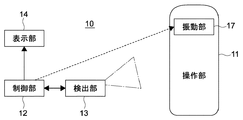
図1は本技術の第1の実施形態に係る入力システム10の概略構成図であり、図2は図1に示した入力システム10の機能ブロック図である。入力システム10は操作部11と制御部12と検出部13と表示部14とを具備する。
<First Embodiment>
[overall structure]
FIG. 1 is a schematic configuration diagram of an
操作部11は、ユーザの手hによる入力操作を受ける。入力システム10は、操作部11の内部に、振動部17(図2参照)を有する。制御部12は振動部17を駆動するための信号を無線で発信するアンテナ19を有する。検出部13及び表示部14は有線で制御部12に接続されている。
The
操作部11は入力デバイスとして構成され、ユーザは手hで操作部11を握り、操作部11を移動させることにより入力操作を行なう。検出部13は、操作部11の位置をユーザの入力操作として検出し、検出結果を制御部12に出力する。制御部12は検出部13から入力された検出結果に基づいて、表示部14の画面14aへの表示を行なう。
The
[操作部の構成]
操作部11は、ユーザが手hで握りやすいように棒状に形成された筐体と、筐体内に配置された振動部17と、を有する。振動部17は振動可能であり、操作部11は振動部17の振動が筐体を介してユーザの手hに良好に伝達されるように構成されている。
[Configuration of operation unit]
The
振動部17は、制御部12によってオン状態とオフ状態とに切り替えられる。オン状態は振動部17が振動可能な状態であり、オフ状態は振動部17が振動不能な状態である。
オン状態における振動部17の振動方向は等方的であっても異方的であってもよい。振動部17は、少なくとも一方向に振動可能であればよいが、複数の方向に振動可能であってもよい。複数の方向に振動可能な振動部17は、制御部12によってその振動方向を制御可能な構成を有していてもよい。振動部17としては、モータをはじめとする様々なアクチュエータを用いたものを採用することができる。
The
The vibration direction of the
操作部11には、その移動以外の入力操作がユーザによってなされることが可能なように構成されていてもよい。その場合、操作部11の筐体に露出した操作ボタンやスライドレバーなどの構成が適宜設けられる。
The
[検出部の構成]
検出部13には、操作部11の位置を検出することが可能なCCD(Charge Coupled Device Image Sensor)イメージセンサが用いられている。検出部13に用いることが可能なセンサは、CCDイメージセンサに限らず、例えば、CMOS(Complementary Metal Oxide Semiconductor)イメージセンサでもよい。
[Configuration of detector]
The
検出部13における操作部11の位置を検出するタイミングは制御部12によって制御される。具体的には、検出部13は、制御部12から送信されるタイミング信号を受信するごとに操作部11の位置を検出する。なお、検出部13は、常に操作部11の位置をモニタリングする構成でもよいが、所定のタイミングで操作部11の位置を検出する構成の方が入力システム10全体としての消費電力が低減される。
The timing of detecting the position of the
[制御部の構成]
制御部12には、一般的なパーソナルコンピュータが用いられる。制御部12は、検出部13から入力された検出結果(操作部11の位置情報)を処理し、表示部14及び操作部11に出力することができればよい。そのため、制御部12には、一般的なパーソナルコンピュータの全ての構成要素が含まれる必要はない。制御部12に搭載されたアンテナ19としては、制御部12による出力信号を操作部11に送信可能な構成を有するものであればよい。
[Configuration of control unit]
The
[表示部の構成]
表示部14には、一般的な画面14aを備えたディスプレイが用いられる。表示部14に用いられるディスプレイの方式に制限はない。そのようなディスプレイの方式としては、例えば、液晶、プラズマ、有機EL(Electroluminescence)が挙げられる。
[Configuration of display section]
As the
[入力システムの機能]
入力システム10では、制御部12が検出部13で検出されたユーザの手hによる操作部11の入力操作に基づいて振動部17をオフ状態からオン状態にするとともに所定の駆動を実行することで、ユーザの手hに弾性感を提示するように構成されている。
[Input system functions]
In the
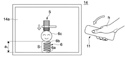
図3A、図3B、及び図3Cは、表示装置14における画面14aの表示と、操作部11の動作と、を模式的に示した図である。画面14aには、ユーザの手hによる操作部11への入力操作によって移動する操作対象であるおもちゃのハンマー5と、ハンマー5からの作用を受けるオブジェクトであるばねおもちゃ6と、が画像として表示されている。
3A, 3B, and 3C are diagrams schematically showing the display of the
ハンマー5としては、樹脂で形成され、打撃部が蛇腹状である一般的なものを想定している。ばねおもちゃ6としては、下端部6aが固定されたばねSと、ばねSの上端部6bに取り付けられた球状の頭部6cと、を有するものを想定している。頭部6cは上下動可能であるものとし、ばねSは頭部6cの上下動に合わせて伸縮可能であるものとした。図3Aに示すように、ばねおもちゃ6のばねSの自然長(下端部6aと上端部6bとの間の距離)をaとした。
The
制御部12は、検出部13の検出結果に基づいてハンマー5がばねおもちゃ6の頭部6cを叩く一連の動作を画面14aに表示するとともに、当該動作に伴ってハンマー5に加わるであろうばねSの弾性に応じた仮想的な刺激を再現するように構成されている。制御部12は、ハンマー5に加わるであろう仮想的な刺激を、操作部11内の振動部17を振動させることにより再現し、ユーザにばねSの弾性感を提示する。
The
画面14aが図3Aに示す状態のときに、ユーザが操作部11を振り降ろす入力操作を行なうと、検出部13が操作部11の位置を逐次検出し、検出結果を制御部12に出力する。制御部12は、検出部13の検出結果に基づいて、操作部11の動作に対応するハンマー5の動作を画面14aに表示する。具体的には、制御部12は、ハンマー5がばねおもちゃ6の頭部6cまで移動し、さらにハンマー5がばねおもちゃ6の頭部6cを下方に押し下げるとともにばねおもちゃ6のばねSが収縮する動作を画面14aに表示する。
When the user performs an input operation of swinging down the
また、反対に、画面14aが図3Bに示す状態のときに、ユーザが操作部11を上昇させる入力操作を行なうと、検出部13が操作部11の位置を逐次検出し、検出結果を制御部12に出力する。制御部12は、検出部13の検出結果に基づいて、操作部11の動作に対応するハンマー5の動作を画面14aに表示する。具体的には、制御部12は、ハンマー5がばねおもちゃ6の頭部6cとともに上昇し、ばねおもちゃ6のばねSが伸長する動作を画面14aに表示する。
On the other hand, when the user performs an input operation for raising the
ここで、図3Bに示すように、画面14aに、ハンマー5がばねおもちゃ6のばねSを自然長aより短いa1に収縮させている表示がなされている場合を想定する。
Here, as shown in FIG. 3B, on the
実際のばねは、そのばね定数を比例定数として、収縮量が大きいほど弾性力が大きくなる。そのため、ユーザは、ハンマー5を移動させる際に、ばねSの収縮量が大きいほどハンマー5がばねおもちゃ6の頭部6cから受ける抵抗力も大きくなると予測する。制御部12は、ハンマー5がばねおもちゃ6の頭部6cから受ける抵抗力が大きくなる弾性感を、操作部11における振動部17の振動の振幅Aを大きくすることにより表現する。
The actual spring has its spring constant as a proportional constant, and the elastic force increases as the contraction amount increases. Therefore, the user predicts that when the
具体的には、ばねSが自然長aより短いa1の場合に、制御部12は、ハンマー5がばねおもちゃ6の頭部6cをさらに押し下げるときの振幅Aを以下の関数で決定することが可能である。
Specifically, when the spring S is a 1 shorter than the natural length a, the
A=k1×(a―a1)2+l1 (k1及びl1は所定の定数である。) ・・・(1) A = k 1 × (aa 1 ) 2 + l 1 (k 1 and l 1 are predetermined constants) (1)
ここで、長さ(a―a1)がばねSの収縮量の大きさを表している。振動部17の振幅Aを表す関数は、収縮量(a―a1)の2次関数(1)に限らず、収縮量(a―a1)を変数とする他の関数であってもよい。そのような関数としては、例えば、収縮量(a―a1)の1次関数や、収縮量(a―a1)の3次関数が挙げられる。収縮量(a―a1)の1次関数を用いる場合には関数(1)を用いる場合よりもばね定数の小さいばねSを表現することができ、収縮量(a―a1)の3次関数を用いる場合には関数(1)を用いる場合よりもばね定数の大きいばねSを表現することができる。
Here, the length (aa 1 ) represents the amount of contraction of the spring S. Function representing the amplitude A of the
次に、図3Bに示すばねSが長さa1の状態からばねSが自然長aの状態に戻ってから、さらにユーザが操作部11を上昇させる入力操作を行なう場合について説明する。
Next, the case where the user performs an input operation for raising the
本実施形態では、ハンマー5がばねおもちゃ6の頭部6cに接触すると、ハンマー5がばねおもちゃ6の頭部6cに吸着することとしている。したがって、画面14aにおいてばねSが長さa1から自然長aに戻ってから、ユーザがさらに操作部11を上昇させる入力操作を行なうと、図3Cに示すように、制御部12は、ばねおもちゃ6の頭部6cがハンマー5とともに上昇し、ばねおもちゃ6のばねSが伸長する動作を画面14aに表示する。
In the present embodiment, when the
反対に、画面14aが図3Cに示す状態から、ユーザが操作部11を下降させる入力操作を行なうと、制御部12は、ハンマー5がばねおもちゃ6の頭部6cとともに下降し、ばねおもちゃ6のばねSが収縮する動作を画面14aに表示する。
On the other hand, when the user performs an input operation for lowering the
ここで、図3Cに示すように、画面14aに、ハンマー5がばねおもちゃ6のばねSを自然長aより長いa2に伸長させている表示がなされている場合を想定する。
Here, as shown in FIG. 3C, the
実際のばねは、そのばね定数を比例定数として、伸長量が大きいほど弾性力が大きくなる。そのため、ユーザは、ハンマー5を移動させる際に、ばねSの伸長量が大きいほどハンマー5がばねおもちゃ6の頭部6cから受ける抵抗力も大きくなると予測する。制御部12は、ハンマー5がばねおもちゃ6の頭部6cから受ける抵抗力が大きくなる弾性感を、操作部11における振動部17の振動の振幅Aを大きくすることにより表現する。
The actual spring has its spring constant as a proportional constant, and the elastic force increases as the extension amount increases. Therefore, when moving the
具体的には、ばねSが自然長aより長いa2の場合に、制御部12は、ハンマー5がばねおもちゃ6の頭部6cを引き上げる際の振幅Aを以下の関数で決定することが可能である。
Specifically, when the spring S is a 2 longer than the natural length a, the
A=k2×(a2―a)2+l2 (k2及びl2は所定の定数である。) ・・・(2) A = k 2 × (a 2 −a) 2 + l 2 (k 2 and l 2 are predetermined constants) (2)
ここで、長さ(a2―a)がばねSの伸長量の大きさを表している。振動部17の振幅Aを表す関数は、伸長量(a2―a)の2次関数(2)に限らず、伸長量(a2―a)を変数とする他の関数であってもよい。そのような関数としては、例えば、長さ(a2―a)の1次関数や、伸長量(a2―a)の3次関数が挙げられる。伸長量(a2―a)の1次関数を用いる場合には関数(2)を用いる場合よりもばね定数の小さいばねSを表現することができ、伸長量(a2―a)の3次関数を用いる場合には関数(2)を用いる場合よりもばね定数の大きいばねSを表現することができる。
Here, the length (a 2 -a) represents the amount of extension of the spring S. Function representing the amplitude A of the
また、本実施形態では、画面14aにおいてばねおもちゃ6のばねSが自然長aよりも伸長することにより所定の長さになったときに、ばねSの弾性力が、ハンマー5とばねおもちゃ6の頭部6cとの吸着力より大きくなり、ハンマー5がばねおもちゃ6の頭部6cから離れることとしている。このとき、制御部12は、ハンマー5がばねおもちゃ6の頭部6cから離れるとともにばねおもちゃ6のばねSが自然長aに戻る動作を表示し、再び画面14aの表示を図3Aの状態に戻す。
In the present embodiment, when the spring S of the
なお、定数k1、k2、l1、及びl2の値は任意に決定可能である。定数l1及びl2がゼロである場合には、ばねSが自然長aである場合の振動部17の振幅Aはゼロとなる。一方、定数l1及びl2がゼロより大きい場合には、ばねSが自然長aである場合の振動部17の振幅Aはゼロより大きい。定数l1及びl2としては、例えば、振動検出閾値の観点から数μmとすることができる。
また、振動部17がオン状態の場合には、振動部17の振幅Aは、関数(1)及び関数(2)によって制御される。一方、振動部17がオフ状態の場合には、振動部17の振幅Aは、関数(1)及び関数(2)に関わらずゼロである。
Note that the values of the constants k 1 , k 2 , l 1 , and l 2 can be arbitrarily determined. When the constants l 1 and l 2 are zero, the amplitude A of the
When the
なお、関数(1)と関数(2)とをまとめると、ばねSの長さxの場合に、ハンマー5がばねおもちゃ6の頭部6cを移動させるときの振幅Aは、以下の関数で表される。ここでは、k1=k2=k、かつl1=l2=lとしている。
When the functions (1) and (2) are summarized, the amplitude A when the
A=k×|a―x|2+l (k及びlは所定の定数である。) ・・・(3) A = k × | a−x | 2 + l (k and l are predetermined constants) (3)
ここで、長さ|a―x|がばねSの変位量を示している。 Here, the length | a−x | indicates the amount of displacement of the spring S.
図4は、以上の記載に基づいた制御部12における処理の流れを示したフローチャートである。図4には、ハンマー5がばねおもちゃ6の頭部6cに接触した状態における制御部12の処理の流れを示している。
FIG. 4 is a flowchart showing the flow of processing in the
まず、制御部12は、ユーザによる入力操作の有無を判断し、ユーザによる入力操作が無い場合には振動部17をオフ状態にしたまま処理を終了する。制御部12は、ユーザによる入力操作が有る場合には、振動部17をオン状態にし、ばねおもちゃ6のばねSが収縮状態か伸長状態かを判断する。なお、図4では、ばねSが自然長aである場合を伸長状態に含めたが、ばねSが自然長aである場合を収縮状態に含めてもよい。
First, the
ばねSが自然長より短い収縮状態である場合、制御部12は、ユーザによる入力操作がばねSの収縮方向か伸長方向かを判断する。ユーザによる入力操作がばねSを収縮させる収縮方向である場合(ばねSが自然長よりもさらに収縮する場合)には、変位量を算出した結果に基づいて振動部17の振幅Aを増加させる。反対に、ユーザによる入力操作がばねSを伸長させる伸長方向である場合(ばねSが自然長に戻るように伸長する場合)には、変位量を算出した結果に基づいて振動部17の振幅Aを減少させる。
When the spring S is in the contracted state shorter than the natural length, the
一方、ばねSが自然長より長い伸長状態である場合、制御部12は、ユーザによる入力操作がばねSの伸長方向か収縮方向かを判断する。ユーザによる入力操作がばねSを伸長させる伸長方向である場合(ばねSが自然長よりもさらに伸長する場合)には、変位量を算出した結果に基づいて振動部17の振幅Aを増加させる。反対に、ユーザによる入力操作がばねSを収縮させる収縮方向である場合(ばねSが自然長に戻るように収縮する場合)には、変位量を算出した結果に基づいて振動部17の振幅Aを減少させる。
On the other hand, when the spring S is in the extended state longer than the natural length, the
そして、制御部12は、画面14aに表示される画像を、上記各場合における画像に更新する。
And the
また、制御部12は、ユーザに対してよりリアルな弾性感を提示するために、ばねSの長さxに加えて、他の変数を含む関数を用いて振動部17の振幅Aを決定してもよい。そのような他の変数としては、例えば、操作部11の入力操作に基づくハンマー5の移動速度や加速度が挙げられる。
Further, the
図5は、ハンマー5の移動速度を変数として含む関数を用いた制御部12における処理の流れを示したフローチャートである。図5には、ハンマー5がばねおもちゃ6の頭部6cに接触した状態における制御部12の処理の流れを示している。制御部12が、ばねおもちゃ6のばねSが収縮状態か伸長状態かを判断するまでの流れは図4と同様である。
FIG. 5 is a flowchart showing a flow of processing in the
ばねSが自然長より短い収縮状態である場合、制御部12は、ユーザによる入力操作がばねSの収縮方向か伸長方向かを判断する。ユーザによる入力操作がばねSを収縮させる収縮方向である場合(ばねSが自然長よりもさらに収縮する場合)には、移動速度を算出した結果に基づいて振動部17の振幅Aを増加させる。反対に、ユーザによる入力操作がばねSを伸長させる伸長方向である場合(ばねSが自然長に戻るように伸長する場合)には、移動速度を算出した結果に基づいて振動部17の振幅Aを減少させる。
When the spring S is in the contracted state shorter than the natural length, the
一方、ばねSが自然長より長い伸長状態である場合、制御部12は、ユーザによる入力操作がばねSの伸長方向か収縮方向かを判断する。ユーザによる入力操作がばねSを伸長させる伸長方向である場合(ばねSが自然長よりもさらに伸長する場合)には、移動速度を算出した結果に基づいて振動部17の振幅Aを増加させる。反対に、ユーザによる入力操作がばねSを収縮させる収縮方向である場合(ばねSが自然長に戻るように収縮する場合)には、移動速度を算出した結果に基づいて振動部17の振幅Aを減少させる。
On the other hand, when the spring S is in the extended state longer than the natural length, the
そして、制御部12は、画面14aに表示される画像を、上記各場合における画像に更新する。
And the
次に、制御部12における振動部17の周波数fの制御について説明する。振動部17がオン状態の場合には、振動部17の周波数fは、制御部12によって所定の条件で制御される。一方、振動部17がオフ状態の場合には、振動部17の周波数fはゼロである。
オン状態において、制御部12は、振動部17の周波数fを一定としても、適宜変更してもよい。制御部12は、振動部17の周波数fを適宜変更することにより、ばねSの弾性感をよりリアルに表現することが可能である。
Next, control of the frequency f of the
In the on state, the
例えば、制御部12は、振動部17の振幅Aを関数(3)で決定したことと同じ要領で、以下の関数(4)で振動部17の周波数fを決定することが可能である。
For example, the
f=m/|a―x|+n (m及びnは定数である。) ・・・(4) f = m / | ax− + n (m and n are constants) (4)
振動部17の周波数fを表す関数は、関数(4)に限らず、変位量|a―x|を変数とする他の関数であってもよい。そのような関数としては、関数(4)と同様に、変位量|a―x|が大きくなるにつれて、周波数fが小さくなるものであることが望ましい。
The function representing the frequency f of the
関数(4)によると、ばねSの自然長aからのばねSの長さxに応じて振動部17の周波数fが一義的に決定される。これにより、ユーザは、ばねSの長さxに応じて、ばねSが自然長に戻ろうとする感覚を覚える。
According to the function (4), the frequency f of the vibrating
具体的には、ばねSの長さxが自然長aより短い場合、ばねSがさらに収縮するとき周波数fが低下する。これにより、ユーザはばねSの収縮が妨げられる感覚(減速感)を覚える。また、ばねSが伸長するとき周波数fが上昇する。これにより、ユーザはばねSの伸長が促進される感覚(加速感)を覚える。 Specifically, when the length x of the spring S is shorter than the natural length a, the frequency f decreases when the spring S further contracts. As a result, the user feels a sense that the spring S is prevented from contracting (deceleration). Further, when the spring S extends, the frequency f increases. Thereby, the user feels a sense (acceleration feeling) that the extension of the spring S is promoted.
反対に、ばねSの長さxが自然長aより長い場合、ばねSがさらに伸長するとき周波数fが低下する。これにより、ユーザはばねSの伸長を妨げられる感覚(減速感)を覚える。また、ばねSが収縮するとき周波数fが上昇する。これにより、ユーザはばねSの収縮が促進される感覚(加速感)を覚える。 On the other hand, when the length x of the spring S is longer than the natural length a, the frequency f decreases when the spring S further expands. As a result, the user feels a sense (deceleration) that prevents the spring S from extending. Further, when the spring S contracts, the frequency f increases. Thereby, the user feels a sense (acceleration feeling) that the contraction of the spring S is promoted.
なお、定数m及びnの値は任意に決定可能である。定数nがゼロである場合には、ばねSが自然長aである場合の振動部17の周波数fはゼロとなる。一方、定数nがゼロより大きい場合には、ばねSが自然長aである場合の振動部17の周波数fはゼロより大きい。定数nとしては、例えば100Hz程度とすることができる。
Note that the values of the constants m and n can be arbitrarily determined. When the constant n is zero, the frequency f of the
図6は、以上の記載に基づいた制御部12における処理の流れを示したフローチャートである。図6には、ハンマー5がばねおもちゃ6の頭部6cに接触した状態における制御部12の処理の流れを示している。制御部12が、ばねおもちゃ6のばねSが収縮状態か伸長状態かを判断するまでの流れは図4と同様である。
FIG. 6 is a flowchart showing the flow of processing in the
ばねSが自然長より短い収縮状態である場合、制御部12は、ユーザによる入力操作がばねSの収縮方向か伸長方向かを判断する。ユーザによる入力操作がばねSを収縮させる収縮方向である場合(ばねSが自然長よりもさらに収縮する場合)には、変位量|a―x|を算出した結果に基づいて振動部17の周波数fを低下させる。反対に、ユーザによる入力操作がばねSを伸長させる伸長方向である場合(ばねSが自然長に戻るように伸長する場合)には、変位量|a―x|を算出した結果に基づいて振動部17の周波数fを上昇させる。
When the spring S is in the contracted state shorter than the natural length, the
一方、ばねSが自然長より長い伸長状態である場合、制御部12は、ユーザによる入力操作がばねSの伸長方向か収縮方向かを判断する。ユーザによる入力操作がばねSを伸長させる伸長方向である場合(ばねSが自然長よりもさらに伸長する場合)には、変位量|a―x|を算出した結果に基づいて振動部17の周波数fを低下させる。反対に、ユーザによる入力操作がばねSを収縮させる収縮方向である場合(ばねSが自然長に戻るように収縮する場合)には、変位量|a―x|を算出した結果に基づいて振動部17の周波数fを上昇させる。
On the other hand, when the spring S is in the extended state longer than the natural length, the
そして、制御部12は、画面14aに表示される画像を、上記各場合における画像に更新する。
And the
また、周波数fを操作部11の入力操作の緩急によって変更してもよい。制御部12は、周波数fを、操作部11への入力操作に基づくハンマー5の移動速度vを変数とする以下の関数で決定することが可能である。
Further, the frequency f may be changed depending on the speed of the input operation of the
f=pv+q (p及びqは定数である。) ・・・(5) f = pv + q (p and q are constants) (5)
振動部17の周波数fを表す関数は、関数(5)に限らず、操作部11への入力操作に基づくハンマー5の速度vを変数とする他の関数であってもよい。また、振動部17の周波数fを表す関数は、操作部11への入力操作に基づくハンマー5の加速度を変数とする関数であってもよい。
The function representing the frequency f of the
なお、定数p及びqの値は任意に決定可能である。定数qがゼロである場合には、ハンマー5の移動速度vがゼロである場合の振動部17の周波数fはゼロとなる。一方、定数qがゼロより大きい場合には、ハンマー5の移動速度vである場合の振動部17の周波数fはゼロより大きい。定数qとしては、例えば100Hz程度とすることができる。
Note that the values of the constants p and q can be arbitrarily determined. When the constant q is zero, the frequency f of the
また、制御部12は、周波数fの変化量Δfを、操作部11への入力操作に基づくハンマー5の移動速度vを変数とする以下の関数(6)で決定することも可能である。
Further, the
Δf=rv (rは定数である。) ・・・(6) Δf = rv (r is a constant) (6)
Δfを表す関数は、関数(6)に限らず、操作部11への入力操作に基づくハンマー5の速度vを変数とする他の関数であってもよい。また、Δfを表す関数は、操作部11への入力操作に基づくハンマー5の加速度を変数とする関数であってもよい。なお、定数rの値は任意に決定可能である。
The function representing Δf is not limited to the function (6), but may be another function using the speed v of the
図7は、以上の記載に基づいた制御部12における処理の流れを示したフローチャートである。図7には、ハンマー5がばねおもちゃ6の頭部6cに接触した状態における制御部12の処理の流れを示している。制御部12が、ばねおもちゃ6のばねSが収縮状態か伸長状態かを判断するまでの流れは図4と同様である。
FIG. 7 is a flowchart showing the flow of processing in the
ばねSが自然長より短い収縮状態である場合、制御部12は、ユーザによる入力操作がばねSの収縮方向か伸長方向かを判断する。ユーザによる入力操作がばねSを収縮させる収縮方向である場合(ばねSが自然長よりもさらに収縮する場合)には、移動速度vを算出した結果に基づいて振動部17の周波数fをΔfだけ低下させる。反対に、ユーザによる入力操作がばねSを伸長させる伸長方向である場合(ばねSが自然長に戻るように伸長する場合)には、移動速度vを算出した結果に基づいて振動部17の周波数fをΔfだけ上昇させる。
When the spring S is in the contracted state shorter than the natural length, the
一方、ばねSが自然長より長い伸長状態である場合、制御部12は、ユーザによる入力操作がばねSの伸長方向か収縮方向かを判断する。ユーザによる入力操作がばねSを伸長させる伸長方向である場合(ばねSが自然長よりもさらに伸長する場合)には、移動速度vを算出した結果に基づいて振動部17の周波数fをΔfだけ低下させる。反対に、ユーザによる入力操作がばねSを収縮させる収縮方向である場合(ばねSが自然長に戻るように収縮する場合)には、移動速度vを算出した結果に基づいて振動部17の周波数fをΔfだけ上昇させる。
On the other hand, when the spring S is in the extended state longer than the natural length, the
そして、制御部12は、画面14aに表示される画像を、上記各場合における画像に更新する。
And the
以上述べたように、ユーザの操作部11への入力操作に基づいてハンマー5が移動する場合、制御部12がユーザにリアルな弾性感を提示するように振動部17の振動条件(振幅A及び周波数f)を決定することができる。具体的には、制御部12は、操作部11の入力操作に基づいて、関数(3)や関数(4)や関数(5)などを適宜組み合わせた関数を用いて振動部17の振動条件(振幅A及び周波数f)を決定することができる。
As described above, when the
また、上述したように、本実施形態に係る入力システム10は、ユーザが視認する画面14aにおけるばねおもちゃ6のばねSの伸縮に合致した振動を受けるように構成されている。これにより、ユーザは触覚的に弾性感を享受するとともに視覚的にも弾性感を享受する。そのため、入力システム10はユーザに対して実際のばねから受ける弾性感に非常に近い弾性感を提示することが可能である。
Further, as described above, the
なお、ユーザが操作部11を動かしていない場合(画面14aにおいてハンマー5が移動していない場合)には、制御部12が振動部17の振動条件を適宜決定することが可能である。この場合、制御部12は、振動部17の振動条件を一定にしてもよく、画面14aにおけるハンマー5の位置に基づいて振動部17の振動条件を変更してもよい。
When the user is not moving the operation unit 11 (when the
本実施形態では、制御部12は、ユーザが操作部11を動かしていない場合には、基本的に振動部17を振動させない。ただし、振動している振動部17の振動が突然停止すると、ユーザは違和感を覚える。これは、実際のばねが、弾性変形して停止した後にもしばらくその伸縮方向の振動が残留するというユーザの経験則に基づくものと考えられる。
In the present embodiment, the
これを解決するために、制御部12は、操作部11が停止した後の所定時間Tの間に、振動部17を、操作部11が停止する直前の振幅A1から振幅Aがゼロになるまで、振幅Aを徐々に減衰させる。所定時間Tにおける振幅Aは、例えば、操作部11が静止状態になってからの経過時間tを用いて以下の関数で表すことができる。
In order to solve this, the
A=((T―t)/T)A1 A = ((T−t) / T) A 1
<第2の実施形態>
[全体構成]
図8は本技術の第2の実施形態に係る入力システム10aの概略構成図であり、図9は図8に示した入力システム10aの機能ブロック図である。本実施形態に係る入力システム10aは、以下に示す構成以外は、第1の実施形態に係る入力システム10と同様に構成されている。入力システム10aの検出部13aは、操作部11a内に配置されている。操作部11a及び表示部14はともに有線で制御部12に接続されている。
<Second Embodiment>
[overall structure]
FIG. 8 is a schematic configuration diagram of an
[操作部及び検出部の構成]
操作部11aは、入力デバイスとして構成され、ユーザの手hに握られて入力操作を受けるレバー部11a1と、レバー部11a1がその下端部を支点として移動可能なようにレバー部11a1の下端部を支持する台座部11a2と、を有するジョイスティックである。振動部17はレバー11a1内に配置されており、検出部13aは台座部11a2内に配置されていている。
[Configuration of operation unit and detection unit]
The
検出部13aは、ユーザによる操作部11aのレバー11a1への入力操作を検出する。検出部13aは、レバー部11a1の動作を検出し、検出結果を制御部12に出力する。検出部13aは、レバー部11a1の下端部の動作を検出可能なセンサであればその種類は限定されない。そのような検出部13aの構成としては、変位センサ、速度センサ、加速度センサ、角度センサ、角速度センサなどを用いた構成が挙げられる。
The detection unit 13a detects an input operation to the lever 11a1 of the
[操作部及び検出部の変形例]
操作部11aの形状は、第1の実施形態に係る操作部11と同様でもよい。つまり、操作部11aは、棒状に形成された筐体内に振動部17及び検出部13aが配置された構成であってもよい。したがって、検出部13aは操作部11aとともに動作する。したがって、検出部13aの構成としては、自らの動作を検出可能ものが用いられる。このような検出部13aの構成としては、例えば、3軸モーションセンサや6軸モーションセンサを用いた構成が挙げられる。
[Modification of operation unit and detection unit]
The shape of the
[入力システムの機能]
入力システム10aでは、制御部12が検出部13aで検出されたユーザの手hによる操作部11aの入力操作に基づいて振動部17を駆動することで、ユーザの手hに弾性感を提示するように構成されている。
[Input system functions]
In the
図10A、図10B、及び図10Cは、表示装置14における画面14aの表示と、操作部11aの動作と、を模式的に示した図である。画面14aには、ユーザの手hによる操作部11aへの入力操作によって移動する操作対象である人差し指を延ばした手の形のポインタ15と、ポインタ15からの作用を受けるオブジェクトであるゴムボール16と、が画像として表示されている。
10A, 10B, and 10C are diagrams schematically showing the display of the
ゴムボール16としては、中心部16aが固定され、ゴム製の外周部16bによって空気が密閉された中心部16aを中心とする球状体を想定している。ゴムボール16の外周部16bは中心部16aを基準として弾性変形可能である。図10Aに示すように、ゴムボール16の定常状態における半径(中心部16aと外周部16bとの間の距離)をbとした。
The
制御部12は、検出部13aの検出結果に基づいてポインタ15(人差し指の先端部)がゴムボール16を突っつく一連の動作を画面14aに表示するとともに、当該動作に伴ってポインタ15に加わるであろうゴムボール16の弾性に応じた仮想的な刺激を再現するように構成されている。制御部12は、ポインタ15に加わるであろう仮想的な刺激を、操作部11a内の振動部17を振動させることにより再現し、ユーザにゴムボール16の弾性感を提示する。
Based on the detection result of the detection unit 13a, the
画面14aが図10Aに示す状態のときに、ユーザが操作部11aのレバー部11a1をポインタ15がゴムボール16の中心部16aに近づくように動かす入力操作を行なうと、検出部13aが操作部11aの動作を検出し、検出結果を制御部12に出力する。制御部12は、検出部13aの検出結果に基づいて、操作部11aのレバー部11a1の動作に対応するポインタ15の動作を画面14aに表示する。具体的には、制御部12は、ポインタ15がゴムボール16の外周部16bまで移動し、さらにポインタ15がゴムボール16の外周部16bを中心部16aに向けて弾性変形させる動作を画面14aに表示する。
When the user performs an input operation for moving the lever portion 11a1 of the
また、反対に、画面14aが図10Bに示す状態のときに、ユーザが操作部11aのレバー部11a1をポインタ15がゴムボール16の中心部16aから遠ざかるように動かす入力操作を行なうと、検出部13aが操作部11aのレバー部11a1の動作を検出し、検出結果を制御部12に出力する。制御部12は、検出部13aの検出結果に基づいて、操作部11aの動作に対応するポインタ15の動作を画面14aに表示する。具体的には、制御部12は、ポインタ15がゴムボール16の外周部16bとともに中心部16aから離れ、ゴムボール16が球状に戻る動作を画面14aに表示する。
Conversely, when the user performs an input operation to move the lever portion 11a1 of the
ここで、図10Bに示すように、画面14aに、ポインタ15がゴムボール16を定常状態の半径bより小さい半径b1に収縮させている表示がなされている場合を想定する。
Here, as shown in FIG. 10B, the
実際のゴムボールは、収縮量が大きいほど内圧が大きくなるため外向きに働く弾性力が大きくなる。そのため、ユーザは、ポインタ15を移動させる際に、ゴムボール16の収縮量が大きいほど、ポインタ15がゴムボール16から受ける抵抗力も大きくなると予測する。制御部12は、ポインタ15がゴムボール16から受ける抵抗力が大きくなる弾性感を、操作部11aにおける振動部17の振動の振幅Aを大きくすることにより表現する。
In actual rubber balls, the greater the amount of shrinkage, the greater the internal pressure, and the greater the elastic force acting outward. Therefore, when moving the
次に、図10Cに示すように、画面14aに、ポインタ15がゴムボール16を定常状態の半径bより大きい半径b2に伸長させている表示がなされている場合を想定する。
Next, as shown in FIG. 10C, the
実際のゴムボールは、伸長量が大きいほど内圧が低くなるため内向きに働く弾性力が大きくなる。そのため、ユーザは、ポインタ15を移動させる際に、ゴムボール16の伸長量が大きいほど、ポインタ15がゴムボール16から受ける抵抗力も大きくなると予測する。制御部12は、ポインタ15がゴムボール16から受ける抵抗力が大きくなる弾性感を、操作部11aにおける振動部17の振動の振幅Aを大きくすることにより表現する。
In an actual rubber ball, the greater the amount of elongation, the lower the internal pressure, so the elastic force acting inward increases. Therefore, when the user moves the
<第3の実施形態>
[全体構成]
図11は本技術の第3の実施形態に係る電子機器20の機能ブロック図である。本実施形態に係る電子機器20は、以下に示す構成以外は、第1の実施形態に係る入力システム10と同様に構成されている。電子機器20は筐体28を具備する。電子機器20では、第1の実施形態に係る入力システム10とは異なり、操作部21、制御部22、検出部23、表示部24、及び振動部27が全て筐体28と一体に構成されている。
<Third Embodiment>
[overall structure]
FIG. 11 is a functional block diagram of an
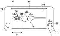
図12A、図12B、及び図12Cは、電子機器20の表示部24における画面24aの表示と、操作部21の動作と、を模式的に示した図である。電子機器20の筐体28はユーザが手で持つことを前提とする大きさに形成されている。電子機器20はユーザが手に持った状態でユーザの指f(親指)によって操作部21への入力操作を受ける。筐体28には操作部21と画面24aとが同一の面に露出している。したがって、電子機器20では、ユーザが画面24aを見ながら指fで操作部21に入力操作を行なうことができる。
12A, 12B, and 12C are diagrams schematically showing the display of the
[操作部及び検出部の構成]
操作部21は、ユーザの指fによって操作される小型のジョイスティックとして構成される。振動部27は操作部21に隣設されている。したがって、振動部27の振動は操作部21を介してユーザの指fに良好に伝達される。
[Configuration of operation unit and detection unit]
The
検出部23は、ユーザによる操作部21への入力操作を検出する。検出部23は、操作部21の動作を検出し、検出結果を制御部22に出力する。検出部23は、操作部21の動作を検出可能なセンサであればその種類は限定されない。そのような検出部23の構成としては、変位センサ、速度センサ、加速度センサ、角度センサ、角速度センサなどを用いた構成が挙げられる。
The
[電子機器の機能]
電子機器20では、制御部22が検出部23で検出されたユーザの指fによる操作部21の入力操作に基づいて振動部27を駆動することで、ユーザの指fに弾性感を提示するように構成されている。
[Functions of electronic devices]
In the
画面24aには、ユーザの指fが操作部21に入力操作を行なうことによって移動する操作対象であるボクシンググローブ25と、ボクシンググローブ25からの作用を受けるオブジェクトであるばねおもちゃ26と、が画像として表示されている。
On the
ボクシンググローブ25としては、画面24aの右端から中央に向かって延びる棒の先端にボクシンググローブを取り付けたものを想定している。ばねおもちゃ26としては、画面24aの左端から中央に向かって延び、左端部26aが固定されたばねSと、ばねSの右端部26bに取り付けられた球状のパンチングボール26cと、を有するものを想定している。パンチングボール26cは左右に動作可能であるものとし、ばねSはパンチングボール26cの動作に合わせて伸縮可能であるものとした。図12Aに示すように、ばねおもちゃ26のばねSの自然長(左端部26aと右端部26bとの間の距離)をcとした。
The
制御部22は、検出部23の検出結果に基づいてボクシンググローブ25がパンチングボール26cにパンチを加える一連の動作を画面24aに表示するとともに、当該動作に伴ってボクシンググローブ25に加わるであろうばねSの弾性に応じた仮想的な刺激を再現するように構成されている。制御部22は、ボクシンググローブ25に加わるであろう仮想的な刺激を、操作部21内の振動部27を振動させることにより再現し、ユーザにばねSの弾性感を提示する。
The
画面24aが図12Aに示す状態のときに、ユーザの指fが操作部21をボクシンググローブ25がパンチングボール26cを左側へ動かす入力操作を行なうと、検出部23が操作部21の動作を検出し、検出結果を制御部22に出力する。制御部22は、検出部23の検出結果に基づいて、操作部21の動作に対応するボクシンググローブ25の動作を画面24aに表示する。具体的には、制御部22は、ボクシンググローブ25がパンチングボール26cまで移動し、さらにボクシンググローブ25がパンチングボール26cを左方向に押し動かすとともにばねおもちゃ26のばねSが収縮する動作を画面24aに表示する。
When the
また、反対に、画面24aが図12Bに示す状態のときに、ユーザが操作部21を右側に移動させる入力操作を行なうと、検出部23が操作部21の動作を検出し、検出結果を制御部22に出力する。制御部22は、検出部23の検出結果に基づいて、操作部21の動作に対応するボクシンググローブ25の動作を画面24aに表示する。具体的には、制御部22は、ボクシンググローブ25がパンチングボール26cとともに右方向に移動し、ばねおもちゃ26のばねSが伸長する動作を画面24aに表示する。
Conversely, when the user performs an input operation to move the
ここで、図12Bに示すように、画面24aに、ボクシンググローブ25がばねおもちゃ26のばねSを自然長cより小さい長さc1に収縮させている表示がなされている場合を想定する。
Here, as shown in FIG. 12B, the
実際のばねは、そのばね定数を比例定数として、収縮量が大きいほど弾性力が大きくなる。そのため、ユーザは、ボクシンググローブ25を移動させる際に、ばねSの収縮量が大きいほどボクシンググローブ25がばねおもちゃ26のパンチングボール26cから受ける抵抗力も大きくなると予測する。制御部22は、ボクシンググローブ25がばねおもちゃ26のパンチングボール26cから受ける抵抗力が大きくなる弾性感を、操作部21における振動部27の振動の振幅Aを大きくすることにより表現する。
The actual spring has its spring constant as a proportional constant, and the elastic force increases as the contraction amount increases. Therefore, when moving the
次に、図12Cに示すように、画面24aに、ボクシンググローブ25がばねおもちゃ26のばねSを自然長cより大きい長さc2に伸長させている表示がなされている場合を想定する。
Next, as shown in FIG. 12C, it is assumed that the
実際のばねは、そのばね定数を比例定数として、伸長量が大きいほど弾性力が大きくなる。そのため、ユーザは、ボクシンググローブ25を移動させる際に、ばねSの伸長量が大きいほどボクシンググローブ25がばねおもちゃ26のパンチングボール26cから受ける抵抗力も大きくなると予測する。制御部22は、ボクシンググローブ25がばねおもちゃ26のパンチングボール26cから受ける抵抗力が大きくなる弾性感を、操作部21における振動部27の振動の振幅Aを大きくすることにより表現する。
The actual spring has its spring constant as a proportional constant, and the elastic force increases as the extension amount increases. Therefore, when moving the
<第4の実施形態>
[全体構成]
図13は本技術の第4の実施形態に係る入力デバイス30の機能ブロック図である。本実施形態に係る入力デバイス30は、以下に示す構成以外は、第1の実施形態に係る入力システム10と同様に構成されている。入力デバイス30は、第1の実施形態に係る入力システム10とは異なり、画面などのユーザが視認できる構成要素を含まない。また入力デバイス30は筐体31を具備する。入力デバイス30では、制御部32、検出部33、及び振動部37が全て筐体31と一体に構成されている。入力デバイス30では、筐体31自体がユーザの手によって入力操作を受ける操作部を構成する。
<Fourth Embodiment>
[overall structure]
FIG. 13 is a functional block diagram of the
[筐体及び検出部の構成]
筐体31はユーザが手で握りやすいように棒状に形成されている。検出部33は筐体31とともに動作する。検出部33の構成としては、自らの動作を検出可能ものが用いられる。このような検出部33の構成としては、例えば、3軸モーションセンサや6軸モーションセンサを用いた構成が挙げられる。
[Configuration of housing and detector]
The
[入力デバイスの機能]
入力デバイス30では、制御部32が検出部33で検出されたユーザによる筐体31への入力操作に基づいて筐体31の振動部37を駆動することで、ユーザに弾性感を提示するように構成されている。
[Input device functions]
In the
入力デバイス30は、仮想空間において、ユーザが操作対象を移動させるためのものである。操作対象は、仮想空間内に存在していれば、ユーザによって視認可能であっても視認不可能であってもよい。仮想空間における操作対象としては、例えば、ヘッドマウントディスプレイ(不図示)を装着したユーザが視認可能なポインタが挙げられる。
The
検出部33は、操作対象の位置を検出し、検出結果を制御部32に出力する。制御部32は、操作対象と、予め決定される空間内の第1の位置と、の位置関係を把握する。制御部32は、操作対象の第1の位置に対する位置関係に基づいて、振動部37を振動させることによって、基準位置にあたかも変形可能な物体があるかのような弾性感をユーザに提示する。
The
一例として、仮想空間において、第1の位置にばねSの一方の端部が固定されており、ばねSの他方の端部が第2の位置にあることを想定し、操作対象が第2の位置にある場合について説明する。ばねSは、ユーザによって視認可能であっても視認不可能であってもよい。この場合、制御部32は、例えば、入力デバイス30へのユーザによる入力操作によって、操作対象が第1の位置に近づく場合に振動部37の振幅を大きくし、操作対象が第1の位置から離れる場合には振動部37の振幅を小さくする。
As an example, in the virtual space, assuming that one end of the spring S is fixed at the first position and the other end of the spring S is at the second position, the operation target is the second. The case where it exists in a position is demonstrated. The spring S may be visible or not visible by the user. In this case, the
以上、本技術の実施形態について説明したが、本技術は上述の実施形態にのみ限定されるものではなく、本技術の要旨を逸脱しない範囲内において種々変更を加え得ることは勿論である。 As mentioned above, although embodiment of this technique was described, this technique is not limited only to the above-mentioned embodiment, Of course, in the range which does not deviate from the summary of this technique, various changes can be added.
例えば、ユーザによる入力操作によって移動する操作対象の形状や、操作対象の作用を受けるオブジェクトの形状は、任意である。また、本明細書で説明した各構成の接続方法はいずれも有線であっても無線であってもよい。 For example, the shape of the operation target that is moved by the input operation by the user and the shape of the object that receives the action of the operation target are arbitrary. Further, any of the connection methods of each configuration described in this specification may be wired or wireless.
また、本技術は、ユーザに対して振動により弾性感以外の感覚も提示する構成とすることができることは勿論である。提示可能な感覚としては、例えば、粘性感や慣性感や摩擦感や衝突感が挙げられる。このような感覚に対応する振動条件が関数で表される場合には、制御部はそれらの関数と上記の関数(3)(4)(5)等を適宜組み合わせて振動条件を決定することができる。 Further, it is needless to say that the present technology can be configured to present a sense other than the elastic feeling to the user by vibration. Examples of sensations that can be presented include a sense of viscosity, a sense of inertia, a sense of friction, and a sense of collision. When vibration conditions corresponding to such feelings are expressed by functions, the control unit may determine the vibration conditions by appropriately combining these functions and the above functions (3), (4), (5), and the like. it can.
なお、本技術は以下のような構成も採ることができる。
(1)ユーザによる入力操作を受ける操作部と、
上記操作部を振動させる振動部と、
上記入力操作を検出する検出部と、
上記検出部で検出された上記入力操作に基づいて上記振動部の振動条件を決定し、決定した上記振動条件で上記振動部を駆動することで、上記ユーザに弾性感を提示するように構成された制御部と、
を具備する入力デバイス。
(2)上記(1)に記載の入力デバイスであって、
上記制御部は、上記入力操作に基づいて画面に表示された操作対象の移動を制御し、上記画面に表示されたオブジェクトと上記操作対象との間の相対位置に基づいて上記振動条件を決定する
入力デバイス。
(3)上記(2)に記載の入力デバイスであって、
上記オブジェクトは、上記操作対象との相対位置に応じて変形可能な画像である
入力デバイス。
(4)上記(3)に記載の入力デバイスであって、
上記オブジェクトは、弾性変形可能な弾性体を示した画像である。
入力デバイス。
(5)上記(2)から(4)のいずれか1つに記載の入力デバイスであって、
上記制御部は、上記操作対象と上記オブジェクトとの間の距離と、上記操作対象の移動速度と、の少なくとも一方を変数とする関数を用いて、上記振動条件を決定する
入力デバイス。
(6)上記(2)から(5)のいずれか1つに記載の入力デバイスであって、
上記制御部は、予め決定される第1の位置と上記操作対象との距離と、上記操作対象の移動速度と、の少なくとも一方を変数とする関数を用いて、上記振動条件を決定する
入力デバイス。
(7)上記(2)から(6)のいずれか1つに記載の入力デバイスであって、
上記制御部は、上記操作対象が予め決定される第1の位置とは異なる第2の位置から上記第1の位置に近づくにつれて、上記振動部の振幅と周波数との少なくとも一方を大きくする
入力デバイス。
(8)上記(2)から(7)のいずれか1つに記載の入力デバイスであって、
上記制御部は、上記操作対象が予め決定される第1の位置とは異なる第2の位置より上記第1の位置から遠ざかるにつれて、上記振動部の振幅と周波数との少なくとも一方を大きくする
入力デバイス。
(9)上記(2)から(8)のいずれか1つに記載の入力デバイスであって、
上記制御部は、上記操作対象を停止した後、上記振動部の振幅を減衰させる
入力デバイス。
(10)ユーザによる入力操作を受ける操作部と、上記操作部を振動させる振動部と、を有する入力デバイスと、
上記入力操作を検出する検出部と、
上記検出部で検出された上記入力操作に基づいて上記振動部の振動条件を決定し、決定した上記振動条件で上記振動部を駆動することで、上記ユーザに弾性感を提示するように構成された制御部と、
を具備する入力システム。
(11)上記(10)に記載の入力システムであって、
上記検出部は、上記入力デバイスと一体に構成されている
入力システム。
(12)ユーザによる入力操作を受ける操作部と、
上記操作部を振動させる振動部と、
上記入力操作を検出する検出部と、
画像を表示する画面を有する表示部と
上記入力操作に基づいて上記画面に表示された操作対象の移動を制御し、上記画面に表示されたオブジェクトと上記操作対象との間の相対位置に基づいて上記振動条件を決定し、決定した上記振動条件で上記振動部を駆動することで、上記ユーザに弾性感を提示するように構成された制御部と、
を具備する電子機器。
(13)ユーザの操作部への入力操作を検出し、
検出した上記入力操作に基づいて上記操作部の振動条件を決定し、
決定した上記振動条件で上記操作部を振動させて、上記ユーザに弾性感を提示する
感覚提示方法。
In addition, this technique can also take the following structures.
(1) an operation unit that receives an input operation by a user;
A vibration unit for vibrating the operation unit;
A detection unit for detecting the input operation;
Based on the input operation detected by the detection unit, the vibration condition of the vibration unit is determined, and the vibration unit is driven under the determined vibration condition, so that an elastic feeling is presented to the user. Control unit,
An input device comprising:
(2) The input device according to (1) above,
The control unit controls movement of an operation target displayed on the screen based on the input operation, and determines the vibration condition based on a relative position between the object displayed on the screen and the operation target. Input device.
(3) The input device according to (2) above,
The input device is an image that can be deformed according to a relative position with respect to the operation target.
(4) The input device according to (3) above,
The object is an image showing an elastic body that can be elastically deformed.
Input device.
(5) The input device according to any one of (2) to (4) above,
The control unit determines the vibration condition using a function having at least one of a distance between the operation target and the object and a moving speed of the operation target as a variable.
(6) The input device according to any one of (2) to (5) above,
The control unit determines the vibration condition using a function having at least one of a predetermined first position and a distance between the operation target and a moving speed of the operation target as a variable. .
(7) The input device according to any one of (2) to (6) above,
The control unit increases at least one of the amplitude and the frequency of the vibration unit as the operation target approaches the first position from a second position different from the first position determined in advance. .
(8) The input device according to any one of (2) to (7) above,
The control unit increases at least one of the amplitude and the frequency of the vibration unit as the operation target moves away from the first position from a second position different from the first position determined in advance. .
(9) The input device according to any one of (2) to (8) above,
The control unit is an input device that attenuates the amplitude of the vibration unit after stopping the operation target.
(10) An input device having an operation unit that receives an input operation by a user, and a vibration unit that vibrates the operation unit;
A detection unit for detecting the input operation;
Based on the input operation detected by the detection unit, the vibration condition of the vibration unit is determined, and the vibration unit is driven under the determined vibration condition, so that an elastic feeling is presented to the user. Control unit,
An input system comprising:
(11) The input system according to (10) above,
The detection unit is an input system configured integrally with the input device.
(12) an operation unit that receives an input operation by a user;
A vibration unit for vibrating the operation unit;
A detection unit for detecting the input operation;
A display unit having a screen for displaying an image, and the movement of the operation target displayed on the screen based on the input operation are controlled, and based on a relative position between the object displayed on the screen and the operation target. A controller configured to determine the vibration condition and drive the vibration unit under the determined vibration condition so as to present elasticity to the user;
An electronic device comprising:
(13) An input operation to the operation unit of the user is detected,
Based on the detected input operation, determine the vibration condition of the operation unit,
A sensation presentation method in which the operation unit is vibrated under the determined vibration condition to present elasticity to the user.
10…入力システム
11…操作部
12…制御部
13…検出部
14…表示部
17…振動部
DESCRIPTION OF
Claims (11)
前記操作部を振動させる振動部と、
前記入力操作を検出する検出部と、
前記検出部で検出された前記入力操作に基づいて前記振動部の振動条件を決定し、決定した前記振動条件で前記振動部を駆動することで、前記ユーザに弾性感を提示するように構成され、前記入力操作に基づいて画面に表示された操作対象の移動を制御し、前記画面に表示されたオブジェクトが前記操作対象によって変形させられるときに前記振動部の周波数を低下させる制御部と
を具備する入力デバイス。 An operation unit for receiving an input operation by a user;
A vibrating section for vibrating the operation section;
A detection unit for detecting the input operation;
Based on the input operation detected by the detection unit, the vibration condition of the vibration unit is determined, and the vibration unit is driven with the determined vibration condition, thereby presenting elasticity to the user. A control unit that controls the movement of the operation target displayed on the screen based on the input operation, and reduces the frequency of the vibration unit when the object displayed on the screen is deformed by the operation target. Input device to be used.
前記制御部は、前記操作対象によって変形させられた前記オブジェクトが元の形状に戻るときに前記振動部の周波数を増加させる The control unit increases the frequency of the vibration unit when the object deformed by the operation target returns to an original shape.
入力デバイス。 Input device.
前記制御部は、前記オブジェクトが前記操作対象によって変形させられるときに前記振動部の振幅を増加させる The control unit increases the amplitude of the vibration unit when the object is deformed by the operation target.
入力デバイス。 Input device.
前記制御部は、前記操作対象によって変形させられた前記オブジェクトが元の形状に戻るときに前記振動部の振幅を低下させる The control unit reduces the amplitude of the vibration unit when the object deformed by the operation target returns to an original shape.
入力デバイス。 Input device.
前記オブジェクトは、弾性変形可能な弾性体を示した画像である
入力デバイス。 The input device according to any one of claims 1 to 4 ,
The input object is an image showing an elastic body that is elastically deformable.
前記制御部は、前記操作対象と前記オブジェクト内にある所定の位置との間の距離と、前記操作対象の移動速度と、の少なくとも一方を変数とする関数を用いて、前記振動条件を決定する
入力デバイス。 The input device according to any one of claims 1 to 5 ,
The control unit determines the vibration condition using a function having at least one of a distance between the operation target and a predetermined position in the object and a moving speed of the operation target as a variable. Input device.
前記制御部は、前記操作対象を停止した後、前記振動部の振幅を減衰させる
入力デバイス。 The input device according to any one of claims 1 to 6 ,
The control unit is an input device that attenuates the amplitude of the vibration unit after stopping the operation target.
前記入力操作を検出する検出部と、
前記検出部で検出された前記入力操作に基づいて前記振動部の振動条件を決定し、決定された前記振動条件で前記振動部を駆動することで、前記ユーザに弾性感を提示するように構成され、前記入力操作に基づいて画面に表示された操作対象の移動を制御し、前記画面に表示されたオブジェクトが前記操作対象によって変形させられるときに前記振動部の周波数を低下させる制御部と
を具備する入力システム。 An input device having an operation unit that receives an input operation by a user, and a vibration unit that vibrates the operation unit;
A detection unit for detecting the input operation;
A vibration condition of the vibration unit is determined based on the input operation detected by the detection unit, and the vibration unit is driven under the determined vibration condition so as to present elasticity to the user. A control unit configured to control movement of the operation target displayed on the screen based on the input operation and to reduce the frequency of the vibration unit when the object displayed on the screen is deformed by the operation target ; Input system provided.
前記検出部は、前記入力デバイスと一体に構成されている
入力システム。 The input system according to claim 8 ,
The detection unit is configured to be integrated with the input device.
前記操作部を振動させる振動部と、
前記入力操作を検出する検出部と、
オブジェクトと、前記入力操作に基づいて移動可能な操作対象と、を表示する画面を有する表示部と
前記検出部で検出された前記入力操作に基づいて振動条件を決定し、決定した前記振動条件で前記振動部を駆動することで、前記ユーザに弾性感を提示するように構成され、前記操作対象の移動を制御し、前記オブジェクトが前記操作対象によって変形させられるときに前記振動部の周波数を低下させる制御部と
を具備する電子機器。 An operation unit for receiving an input operation by a user;
A vibrating section for vibrating the operation section;
A detection unit for detecting the input operation;
A display unit having a screen for displaying an object and an operation target movable based on the input operation ;
Wherein the vibration condition determined based on the detected input operation by the detection unit, by driving the vibrating unit in the determined said vibrating condition, is configured to present an elastic feeling to the user, the operation An electronic apparatus comprising: a control unit that controls movement of a target and reduces a frequency of the vibrating unit when the object is deformed by the operation target .
前記入力操作を検出し、
検出した前記入力操作に基づいて前記操作部の振動条件を決定し、
決定した前記振動条件で前記操作部を振動させて、前記ユーザに弾性感を提示し、
前記オブジェクトが前記操作対象によって変形させられるときに前記操作部の振動の周波数を低下させる
感覚提示方法。 The object and the operation target that can be moved based on the input operation to the operation unit of the user are displayed on the screen.
Detecting the input operation ;
Determine the vibration condition of the operation unit based on the detected input operation,
Vibrating the operation unit under the determined vibration conditions, presenting a sense of elasticity to the user ,
A sensation presentation method for reducing a frequency of vibration of the operation unit when the object is deformed by the operation target .
Priority Applications (4)
| Application Number | Priority Date | Filing Date | Title |
|---|---|---|---|
| JP2012184042A JP6043544B2 (en) | 2012-08-23 | 2012-08-23 | Input device, input system, electronic device, and sensory presentation method |
| US13/962,595 US9489041B2 (en) | 2012-08-23 | 2013-08-08 | Input device, input system, electronic apparatus, and sense presentation method |
| CN201810011158.7A CN108170276B (en) | 2012-08-23 | 2013-08-16 | Input device, input system, electronic device, and sensation presentation method |
| CN201310359418.7A CN103631374B (en) | 2012-08-23 | 2013-08-16 | Input unit, input system, electronic installation and sensation rendering method |
Applications Claiming Priority (1)
| Application Number | Priority Date | Filing Date | Title |
|---|---|---|---|
| JP2012184042A JP6043544B2 (en) | 2012-08-23 | 2012-08-23 | Input device, input system, electronic device, and sensory presentation method |
Publications (3)
| Publication Number | Publication Date |
|---|---|
| JP2014041520A JP2014041520A (en) | 2014-03-06 |
| JP2014041520A5 JP2014041520A5 (en) | 2015-09-24 |
| JP6043544B2 true JP6043544B2 (en) | 2016-12-14 |
Family
ID=50149056
Family Applications (1)
| Application Number | Title | Priority Date | Filing Date |
|---|---|---|---|
| JP2012184042A Active JP6043544B2 (en) | 2012-08-23 | 2012-08-23 | Input device, input system, electronic device, and sensory presentation method |
Country Status (3)
| Country | Link |
|---|---|
| US (1) | US9489041B2 (en) |
| JP (1) | JP6043544B2 (en) |
| CN (2) | CN103631374B (en) |
Families Citing this family (4)
| Publication number | Priority date | Publication date | Assignee | Title |
|---|---|---|---|---|
| WO2015163169A1 (en) * | 2014-04-23 | 2015-10-29 | ソニー株式会社 | Image processing device and method |
| CN106774853A (en) * | 2016-11-28 | 2017-05-31 | 珠海市魅族科技有限公司 | A kind of seismaesthesia feedback method and terminal |
| JP6842368B2 (en) * | 2017-05-19 | 2021-03-17 | 任天堂株式会社 | Information processing programs, information processing systems, information processing devices, and information processing methods |
| US11775071B1 (en) * | 2022-03-08 | 2023-10-03 | Microsoft Technology Licensing, Llc | Haptic feedback from a computing accessory |
Family Cites Families (20)
| Publication number | Priority date | Publication date | Assignee | Title |
|---|---|---|---|---|
| JP3686686B2 (en) * | 1993-05-11 | 2005-08-24 | 松下電器産業株式会社 | Haptic device, data input device, and data input device device |
| CN1149465C (en) * | 1995-10-09 | 2004-05-12 | 任天堂株式会社 | Stereo image processing system |
| US6924787B2 (en) * | 2000-04-17 | 2005-08-02 | Immersion Corporation | Interface for controlling a graphical image |
| JP2002082751A (en) * | 2000-09-08 | 2002-03-22 | Mitsubishi Electric Corp | Device for interaction with virtual space and virtual space system applied with the same |
| US7999812B2 (en) * | 2006-08-15 | 2011-08-16 | Nintendo Co, Ltd. | Locality based morphing between less and more deformed models in a computer graphics system |
| JP2008225690A (en) * | 2007-03-09 | 2008-09-25 | Sony Corp | Vibration body, tactile sense function-equipped input device, and electronic equipment |
| JP4916390B2 (en) * | 2007-06-20 | 2012-04-11 | 任天堂株式会社 | Information processing program, information processing apparatus, information processing system, and information processing method |
| JP2009009412A (en) * | 2007-06-28 | 2009-01-15 | Canon Inc | Information presentation device and information presentation method |
| WO2009035100A1 (en) * | 2007-09-14 | 2009-03-19 | National Institute Of Advanced Industrial Science And Technology | Virtual reality environment creating device, and controller device |
| US8519950B2 (en) * | 2007-11-19 | 2013-08-27 | Nokia Corporation | Input device |
| JP2009134473A (en) * | 2007-11-29 | 2009-06-18 | Sony Corp | Pressing detection sensor, input device and electronic equipment |
| CN102171640B (en) * | 2008-10-01 | 2015-08-05 | 索尼电脑娱乐公司 | Signal conditioning package, information processing method, information recording carrier and program |
| KR101250513B1 (en) * | 2008-10-27 | 2013-04-03 | 소니 컴퓨터 엔터테인먼트 인코포레이티드 | Spherical ended controller with configurable modes |
| KR20120019471A (en) * | 2009-05-07 | 2012-03-06 | 임머숀 코퍼레이션 | Method and apparatus for providing a haptic feedback shape-changing display |
| US8226484B2 (en) * | 2009-08-27 | 2012-07-24 | Nintendo Of America Inc. | Simulated handlebar twist-grip control of a simulated vehicle using a hand-held inertial sensing remote controller |
| JP2011159100A (en) | 2010-02-01 | 2011-08-18 | Nippon Telegr & Teleph Corp <Ntt> | Successive similar document retrieval apparatus, successive similar document retrieval method and program |
| US20120065784A1 (en) * | 2010-09-13 | 2012-03-15 | Philip Feldman | Providing kinetic feedback for computer-human interaction in virtual or remote operation environments |
| CN102609078B (en) * | 2011-01-20 | 2014-12-31 | 宏达国际电子股份有限公司 | Electronic device with tactile feedback and method for providing tactile feedback |
| CN202019421U (en) * | 2011-04-19 | 2011-10-26 | 康佳集团股份有限公司 | Three-dimensional (3D) television with vibration stereo perception function |
| KR101945822B1 (en) * | 2012-03-02 | 2019-02-11 | 삼성전자 주식회사 | Method and apparatus for displaying page |
-
2012
- 2012-08-23 JP JP2012184042A patent/JP6043544B2/en active Active
-
2013
- 2013-08-08 US US13/962,595 patent/US9489041B2/en active Active
- 2013-08-16 CN CN201310359418.7A patent/CN103631374B/en active Active
- 2013-08-16 CN CN201810011158.7A patent/CN108170276B/en active Active
Also Published As
| Publication number | Publication date |
|---|---|
| JP2014041520A (en) | 2014-03-06 |
| US20140059255A1 (en) | 2014-02-27 |
| US9489041B2 (en) | 2016-11-08 |
| CN103631374B (en) | 2018-01-30 |
| CN108170276A (en) | 2018-06-15 |
| CN108170276B (en) | 2020-12-08 |
| CN103631374A (en) | 2014-03-12 |
Similar Documents
| Publication | Publication Date | Title |
|---|---|---|
| JP6431126B2 (en) | An interactive model for shared feedback on mobile devices | |
| JP6591805B2 (en) | System and method for a surface element providing an electrostatic haptic effect | |
| KR102224434B1 (en) | Systems and methods for performing haptic conversion | |
| EP3009914A1 (en) | Haptically-enabled deformable device with rigid component | |
| JP2019050003A (en) | Simulation of tangible user interface interactions and gestures using array of haptic cells | |
| EP3171247B1 (en) | Haptically enabled flexible devices | |
| EP3614236A1 (en) | User interface device | |
| JP6043544B2 (en) | Input device, input system, electronic device, and sensory presentation method | |
| JP2016131018A (en) | Systems and methods for controlling haptic signals | |
| KR20160056834A (en) | Haptic controller | |
| US9001032B2 (en) | Tactile transmission system using glove type actuator device and method thereof | |
| JP2020013549A (en) | Adaptive haptic effect rendering based on dynamic system identification | |
| EP3489804A1 (en) | Haptic accessory apparatus | |
| JP2021182449A (en) | Stimulus transmission device | |
| US20190227630A1 (en) | Input device | |
| WO2023189425A1 (en) | Control device, control method, haptic feedback system, and program product | |
| JP6600269B2 (en) | Three-dimensional shape presentation system and haptic sense presentation device | |
| WO2024053087A1 (en) | Operation device | |
| WO2023189423A1 (en) | Control device, control method, tactile sense presentation system, and program product | |
| WO2019043787A1 (en) | Vibration control device | |
| WO2023189422A1 (en) | Control device, control method, haptic presentation system, and program product | |
| Martínez et al. | The sense of touch as the last frontier in virtual reality technology | |
| JP2023148854A (en) | Control device, control method, haptic feedback system, and computer program | |
| JP2023148853A (en) | Control device, control method, haptic feedback system, and computer program |
Legal Events
| Date | Code | Title | Description |
|---|---|---|---|
| A521 | Request for written amendment filed |
Free format text: JAPANESE INTERMEDIATE CODE: A523 Effective date: 20150806 |
|
| A621 | Written request for application examination |
Free format text: JAPANESE INTERMEDIATE CODE: A621 Effective date: 20150806 |
|
| A977 | Report on retrieval |
Free format text: JAPANESE INTERMEDIATE CODE: A971007 Effective date: 20160420 |
|
| A131 | Notification of reasons for refusal |
Free format text: JAPANESE INTERMEDIATE CODE: A131 Effective date: 20160426 |
|
| A521 | Request for written amendment filed |
Free format text: JAPANESE INTERMEDIATE CODE: A523 Effective date: 20160613 |
|
| TRDD | Decision of grant or rejection written | ||
| A01 | Written decision to grant a patent or to grant a registration (utility model) |
Free format text: JAPANESE INTERMEDIATE CODE: A01 Effective date: 20161101 |
|
| A61 | First payment of annual fees (during grant procedure) |
Free format text: JAPANESE INTERMEDIATE CODE: A61 Effective date: 20161114 |
|
| R150 | Certificate of patent or registration of utility model |
Ref document number: 6043544 Country of ref document: JP Free format text: JAPANESE INTERMEDIATE CODE: R150 |
|
| R250 | Receipt of annual fees |
Free format text: JAPANESE INTERMEDIATE CODE: R250 |
|
| R250 | Receipt of annual fees |
Free format text: JAPANESE INTERMEDIATE CODE: R250 |