JP6038735B2 - Ultrasonic diagnostic apparatus and ultrasonic probe - Google Patents
Ultrasonic diagnostic apparatus and ultrasonic probe Download PDFInfo
- Publication number
- JP6038735B2 JP6038735B2 JP2013130141A JP2013130141A JP6038735B2 JP 6038735 B2 JP6038735 B2 JP 6038735B2 JP 2013130141 A JP2013130141 A JP 2013130141A JP 2013130141 A JP2013130141 A JP 2013130141A JP 6038735 B2 JP6038735 B2 JP 6038735B2
- Authority
- JP
- Japan
- Prior art keywords
- switch
- ground
- voltage power
- primary winding
- connection path
- Prior art date
- Legal status (The legal status is an assumption and is not a legal conclusion. Google has not performed a legal analysis and makes no representation as to the accuracy of the status listed.)
- Active
Links
- 239000000523 sample Substances 0.000 title claims description 23
- 238000004804 winding Methods 0.000 claims description 361
- 230000005669 field effect Effects 0.000 claims description 37
- 238000002604 ultrasonography Methods 0.000 claims description 2
- 230000005540 biological transmission Effects 0.000 description 203
- 230000004048 modification Effects 0.000 description 39
- 238000012986 modification Methods 0.000 description 39
- 238000010586 diagram Methods 0.000 description 15
- 230000000694 effects Effects 0.000 description 11
- 239000000203 mixture Substances 0.000 description 6
- 230000017531 blood circulation Effects 0.000 description 3
- 238000006243 chemical reaction Methods 0.000 description 3
- 238000004590 computer program Methods 0.000 description 2
- 230000000903 blocking effect Effects 0.000 description 1
- 230000006835 compression Effects 0.000 description 1
- 238000007906 compression Methods 0.000 description 1
- 238000001514 detection method Methods 0.000 description 1
- 238000002592 echocardiography Methods 0.000 description 1
- 239000004973 liquid crystal related substance Substances 0.000 description 1
- 238000013507 mapping Methods 0.000 description 1
- 239000004065 semiconductor Substances 0.000 description 1
Images


Classifications
-
- A—HUMAN NECESSITIES
- A61—MEDICAL OR VETERINARY SCIENCE; HYGIENE
- A61B—DIAGNOSIS; SURGERY; IDENTIFICATION
- A61B8/00—Diagnosis using ultrasonic, sonic or infrasonic waves
- A61B8/44—Constructional features of the ultrasonic, sonic or infrasonic diagnostic device
- A61B8/4483—Constructional features of the ultrasonic, sonic or infrasonic diagnostic device characterised by features of the ultrasound transducer
- A61B8/4494—Constructional features of the ultrasonic, sonic or infrasonic diagnostic device characterised by features of the ultrasound transducer characterised by the arrangement of the transducer elements
-
- A—HUMAN NECESSITIES
- A61—MEDICAL OR VETERINARY SCIENCE; HYGIENE
- A61B—DIAGNOSIS; SURGERY; IDENTIFICATION
- A61B8/00—Diagnosis using ultrasonic, sonic or infrasonic waves
- A61B8/56—Details of data transmission or power supply
-
- B—PERFORMING OPERATIONS; TRANSPORTING
- B06—GENERATING OR TRANSMITTING MECHANICAL VIBRATIONS IN GENERAL
- B06B—METHODS OR APPARATUS FOR GENERATING OR TRANSMITTING MECHANICAL VIBRATIONS OF INFRASONIC, SONIC, OR ULTRASONIC FREQUENCY, e.g. FOR PERFORMING MECHANICAL WORK IN GENERAL
- B06B1/00—Methods or apparatus for generating mechanical vibrations of infrasonic, sonic, or ultrasonic frequency
- B06B1/02—Methods or apparatus for generating mechanical vibrations of infrasonic, sonic, or ultrasonic frequency making use of electrical energy
- B06B1/0207—Driving circuits
- B06B1/0223—Driving circuits for generating signals continuous in time
- B06B1/023—Driving circuits for generating signals continuous in time and stepped in amplitude, e.g. square wave, 2-level signal
-
- B—PERFORMING OPERATIONS; TRANSPORTING
- B06—GENERATING OR TRANSMITTING MECHANICAL VIBRATIONS IN GENERAL
- B06B—METHODS OR APPARATUS FOR GENERATING OR TRANSMITTING MECHANICAL VIBRATIONS OF INFRASONIC, SONIC, OR ULTRASONIC FREQUENCY, e.g. FOR PERFORMING MECHANICAL WORK IN GENERAL
- B06B1/00—Methods or apparatus for generating mechanical vibrations of infrasonic, sonic, or ultrasonic frequency
- B06B1/02—Methods or apparatus for generating mechanical vibrations of infrasonic, sonic, or ultrasonic frequency making use of electrical energy
- B06B1/06—Methods or apparatus for generating mechanical vibrations of infrasonic, sonic, or ultrasonic frequency making use of electrical energy operating with piezoelectric effect or with electrostriction
- B06B1/0607—Methods or apparatus for generating mechanical vibrations of infrasonic, sonic, or ultrasonic frequency making use of electrical energy operating with piezoelectric effect or with electrostriction using multiple elements
-
- G—PHYSICS
- G01—MEASURING; TESTING
- G01S—RADIO DIRECTION-FINDING; RADIO NAVIGATION; DETERMINING DISTANCE OR VELOCITY BY USE OF RADIO WAVES; LOCATING OR PRESENCE-DETECTING BY USE OF THE REFLECTION OR RERADIATION OF RADIO WAVES; ANALOGOUS ARRANGEMENTS USING OTHER WAVES
- G01S7/00—Details of systems according to groups G01S13/00, G01S15/00, G01S17/00
- G01S7/52—Details of systems according to groups G01S13/00, G01S15/00, G01S17/00 of systems according to group G01S15/00
- G01S7/52017—Details of systems according to groups G01S13/00, G01S15/00, G01S17/00 of systems according to group G01S15/00 particularly adapted to short-range imaging
- G01S7/52019—Details of transmitters
- G01S7/5202—Details of transmitters for pulse systems
-
- B—PERFORMING OPERATIONS; TRANSPORTING
- B06—GENERATING OR TRANSMITTING MECHANICAL VIBRATIONS IN GENERAL
- B06B—METHODS OR APPARATUS FOR GENERATING OR TRANSMITTING MECHANICAL VIBRATIONS OF INFRASONIC, SONIC, OR ULTRASONIC FREQUENCY, e.g. FOR PERFORMING MECHANICAL WORK IN GENERAL
- B06B2201/00—Indexing scheme associated with B06B1/0207 for details covered by B06B1/0207 but not provided for in any of its subgroups
- B06B2201/20—Application to multi-element transducer
-
- B—PERFORMING OPERATIONS; TRANSPORTING
- B06—GENERATING OR TRANSMITTING MECHANICAL VIBRATIONS IN GENERAL
- B06B—METHODS OR APPARATUS FOR GENERATING OR TRANSMITTING MECHANICAL VIBRATIONS OF INFRASONIC, SONIC, OR ULTRASONIC FREQUENCY, e.g. FOR PERFORMING MECHANICAL WORK IN GENERAL
- B06B2201/00—Indexing scheme associated with B06B1/0207 for details covered by B06B1/0207 but not provided for in any of its subgroups
- B06B2201/50—Application to a particular transducer type
- B06B2201/55—Piezoelectric transducer
Description
本発明の実施形態は超音波診断装置及び超音波プローブに関する。 Embodiments described herein relate generally to an ultrasonic diagnostic apparatus and an ultrasonic probe.
超音波診断装置は、複数の超音波振動子を備えた超音波プローブによって被検体内に超音波を送信し、その被検体からの反射波(超音波エコー)に基づいて、被検体内の断層像データや3次元画像データなどを生成する。 An ultrasonic diagnostic apparatus transmits ultrasonic waves into a subject using an ultrasonic probe having a plurality of ultrasonic transducers, and based on reflected waves (ultrasound echoes) from the subject, Image data, 3D image data, and the like are generated.
超音波診断装置では、トランスの1次巻線に電源を接続して電圧を印加することによって、2次巻線に誘起される電圧により超音波振動子を駆動させる構成をとる場合がある。このような構成とすることで、1次側巻線へ印加される電流の方向を切り替えることにより、2次側巻線に誘起されるパルスの極性を反転させることが可能となる。この構成の超音波診断装置は、プラス電圧信号、該プラス電圧信号の極性が反転したマイナス電圧信号、及びゼロ電圧信号の3レベルの電圧信号を送信信号として超音波振動子へ出力する。また、このような構成の超音波診断装置は、2次巻線に誘起されるパルスのパルス幅を多様に制御することによって、超音波の周波数特性を制御する。 An ultrasonic diagnostic apparatus may be configured to drive an ultrasonic transducer by a voltage induced in a secondary winding by connecting a power source to the primary winding of the transformer and applying a voltage. With such a configuration, the polarity of the pulse induced in the secondary winding can be reversed by switching the direction of the current applied to the primary winding. The ultrasonic diagnostic apparatus having this configuration outputs a positive voltage signal, a negative voltage signal in which the polarity of the positive voltage signal is inverted, and a three-level voltage signal of a zero voltage signal to the ultrasonic transducer as transmission signals. In addition, the ultrasonic diagnostic apparatus having such a configuration controls the frequency characteristics of ultrasonic waves by variously controlling the pulse widths of pulses induced in the secondary winding.
また、DAC(Digital to Analog Converter)及びリニアアンプを用いて電圧信号の電圧レベルを多様に制御することによって超音波の周波数特性を制御する構成の超音波診断装置が知られている。 There is also known an ultrasonic diagnostic apparatus configured to control the frequency characteristics of an ultrasonic wave by variously controlling the voltage level of a voltage signal using a DAC (Digital to Analog Converter) and a linear amplifier.
しかしながら、パルス幅を多様に制御するためには、高いクロック周波数が必要とされる。また、送信信号の立ち上がり特性の影響により、広いパルス幅の送信信号と狭いパルス幅の送信信号とを同等の振幅で超音波振動子へ出力することが困難であった。 However, in order to control the pulse width in various ways, a high clock frequency is required. Further, due to the rise characteristic of the transmission signal, it is difficult to output a transmission signal having a wide pulse width and a transmission signal having a narrow pulse width to the ultrasonic transducer with the same amplitude.
また、DAC(Digital to Analog Converter)及びリニアアンプを用いると、大きな規模の送信回路が必要とされる。この場合、コストが高く、消費電力が大きくなるという問題があった。 In addition, when a DAC (Digital to Analog Converter) and a linear amplifier are used, a large-scale transmission circuit is required. In this case, there is a problem that the cost is high and the power consumption increases.
本発明が解決しようとする課題は、小さな規模の送信回路から多様な電圧レベルの送信信号を超音波振動子へ出力することができる超音波診断装置及び超音波プローブを提供することである。 The problem to be solved by the present invention is to provide an ultrasonic diagnostic apparatus and an ultrasonic probe capable of outputting transmission signals of various voltage levels from a small-scale transmission circuit to an ultrasonic transducer.
実施形態の超音波診断装置は、トランスと、正電圧電源と、負電圧電源と、切替部とを有する。トランスは、1次巻線及び2次巻線を備え、2次巻線に発生した電圧に基づいて超音波振動子を駆動する。正電圧電源は、グランドが有する基準電位とは異なる第1の電位で基準電位との電位差を生じさせる。負電圧電源は、基準電位及び第1の電位とは異なる第2の電位で基準電位との電位差を生じさせる。切替部は、正電圧電源及び負電圧電源のうち少なくとも1つと1次巻線との接続経路を、1次巻線の一端に正電圧電源を接続し1次巻線の他端に負電圧電源を接続する第1の接続経路、他端に正電圧電源を接続し一端に負電圧電源を接続する第2の接続経路、又は正電圧電源若しくは負電圧電源とグランドとを1次巻線を介して接続させるグランド接続経路に切り替える。 The ultrasonic diagnostic apparatus according to the embodiment includes a transformer, a positive voltage power source, a negative voltage power source, and a switching unit. The transformer includes a primary winding and a secondary winding, and drives the ultrasonic transducer based on a voltage generated in the secondary winding. The positive voltage power source generates a potential difference from the reference potential at a first potential different from the reference potential of the ground. The negative voltage power source generates a potential difference from the reference potential at a second potential different from the reference potential and the first potential. The switching unit connects at least one of the positive voltage power source and the negative voltage power source to the primary winding , connects the positive voltage power source to one end of the primary winding, and connects the negative voltage power source to the other end of the primary winding. first connection path connecting the second connection path connecting the negative voltage power supply a positive voltage supply to the connected one to the other, or the primary winding and a positive voltage source or a negative voltage power supply and ground Ru switched to ground connection path for connecting through.
また、実施形態の超音波プローブは、超音波振動子と、トランスと、正電圧電源と、負電圧電源と、切替部とを有する。トランスは、1次巻線及び2次巻線を備え、2次巻線に発生した電圧に基づいて超音波振動子を駆動する。正電圧電源は、グランドが有する基準電位とは異なる第1の電位で基準電位との電位差を生じさせる。負電圧電源は、基準電位及び第1の電位とは異なる第2の電位で基準電位との電位差を生じさせる。切替部は、正電圧電源及び負電圧電源のうち少なくとも1つと1次巻線との接続経路を、1次巻線の一端に正電圧電源を接続し1次巻線の他端に負電圧電源を接続する第1の接続経路、他端に正電圧電源を接続し一端に負電圧電源を接続する第2の接続経路、又は正電圧電源若しくは負電圧電源とグランドとを1次巻線を介して接続させるグランド接続経路に切り替える。 The ultrasonic probe of the embodiment includes an ultrasonic transducer, a transformer, a positive voltage power supply, a negative voltage power supply, and a switching unit. The transformer includes a primary winding and a secondary winding, and drives the ultrasonic transducer based on a voltage generated in the secondary winding. The positive voltage power source generates a potential difference from the reference potential at a first potential different from the reference potential of the ground. The negative voltage power source generates a potential difference from the reference potential at a second potential different from the reference potential and the first potential. The switching unit connects at least one of the positive voltage power source and the negative voltage power source to the primary winding , connects the positive voltage power source to one end of the primary winding, and connects the negative voltage power source to the other end of the primary winding. first connection path connecting the second connection path connecting the negative voltage power supply a positive voltage supply to the connected one to the other, or the primary winding and a positive voltage source or a negative voltage power supply and ground Ru switched to ground connection path for connecting through.
〈第1の実施形態〉
[構成]
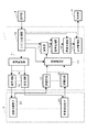
図1は、第1の実施形態に係る超音波診断装置の構成を表すブロック図である。超音波診断装置は、本体部1と、超音波プローブ2と、表示部3と、操作部4とを有する。
<First Embodiment>
[Constitution]
FIG. 1 is a block diagram showing the configuration of the ultrasonic diagnostic apparatus according to the first embodiment. The ultrasonic diagnostic apparatus includes a
(本体部1)
本体部1は、送信回路10と、送信制御部11と、受信回路12と、受信遅延部13と、加算部14と、信号処理部15と、画像生成部16と、表示制御部17と、システム制御部18とを有する。
(Main unit 1)
The
(送信回路10)
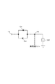
送信回路10は、超音波振動子20ごとに設けられる。図2及び図3は、この実施形態の送信回路10の構成を表す回路図である。図2の端子TEと図3の端子TEとは接続されている。送信回路10は、トランスTRと、正電圧電源V1と、負電圧電源V2と、切替部とを含んで構成される。トランスTRは1次巻線L1及び2次巻線L2を備える。本明細書において、1次巻線L1及び2次巻線L2のプラス側をそれぞれの巻線の巻始め側とする。同様に、1次巻線L1及び2次巻線L2のマイナス側をそれぞれの巻線の巻終わり側とする。また、1次巻線L1のプラス側の端を一端とし、1次巻線L1のマイナス側の端を他端とする。トランスTRは、2次巻線L2に発生した電圧に基づく送信信号を超音波振動子20へ出力して超音波振動子20を駆動する。正電圧電源V1は、グランドより高い電圧の電圧源である。また、正電圧電源V1は、電流を吐き出す。負電圧電源V2は、グランドより低い電圧の電圧源である。また、負電圧電源V2は、電流を吸い込む。なお、例えば送信信号のオーバーシュートを低減するため、トランスTRにおいて、抵抗器R1が1次巻線L1に対して並列に設けられ、抵抗器R2が2次巻線L2に対して並列に設けられてもよい。
(Transmission circuit 10)
The
切替部は、1次巻線L1と正電圧電源V1若しくは負電圧電源V2又はこれら双方との接続経路を、1次巻線L1の一端に正電圧電源V1を接続し1次巻線L1の他端に負電圧電源V2を接続する第1の接続経路、他端に正電圧電源V1を接続し一端に負電圧電源V2を接続する第2の接続経路、一端と他端とを短絡させる第3の接続経路、又は正電圧電源V1若しくは負電圧電源V2とグランドとを1次巻線L1を介して接続させるグランド接続経路に切り替えることによって、2次巻線L2に電圧を変化させて発生させる。グランド接続経路は、正電圧電源V1、1次巻線L1の一端、1次巻線L1の他端、グランドの順に対して電流が順方向となる第1のグランド接続経路を含む。 The switching unit connects the primary winding L1 and the positive voltage power source V1, the negative voltage power source V2, or both of them, connects the positive voltage power source V1 to one end of the primary winding L1, and other than the primary winding L1. A first connection path for connecting the negative voltage power supply V2 to one end, a second connection path for connecting the positive voltage power supply V1 to the other end and connecting the negative voltage power supply V2 to one end, and a third for short-circuiting one end and the other end. Is switched to a ground connection path for connecting the positive voltage power supply V1 or the negative voltage power supply V2 and the ground via the primary winding L1, and the voltage is generated in the secondary winding L2. The ground connection path includes a positive voltage power supply V1, one end of the primary winding L1, the other end of the primary winding L1, and a first ground connection path in which the current is forward with respect to the order of the ground.
切替部は、正電圧側スイッチと、負電圧側スイッチと、グランド側スイッチとを有する。正電圧側スイッチは、1次巻線L1の両端のそれぞれと正電圧電源V1との間に設けられたスイッチである。この実施形態におけるスイッチS1とスイッチS2とが正電圧側スイッチに相当する。負電圧側スイッチは、1次巻線L1の両端のそれぞれと負電圧電源V2との間に設けられたスイッチである。この実施形態におけるスイッチS3とスイッチS4とが負電圧側スイッチに相当する。グランド側スイッチは、1次巻線L1の他端とグランドとの間に設けられたスイッチである。この実施形態におけるスイッチS5がグランド側スイッチに相当する。 The switching unit includes a positive voltage side switch, a negative voltage side switch, and a ground side switch. The positive voltage side switch is a switch provided between both ends of the primary winding L1 and the positive voltage power source V1. The switch S1 and the switch S2 in this embodiment correspond to a positive voltage side switch. The negative voltage side switch is a switch provided between each of both ends of the primary winding L1 and the negative voltage power source V2. In this embodiment, the switch S3 and the switch S4 correspond to a negative voltage side switch. The ground side switch is a switch provided between the other end of the primary winding L1 and the ground. The switch S5 in this embodiment corresponds to a ground side switch.
正電圧側スイッチ(スイッチS1、スイッチS2)は、オン時に正電圧電源V1側から1次巻線L1側へ電流が順方向となる電界効果トランジスタ(MOSFET:Metal−Oxide−Semiconductor Field−Effect Transistor)であり、いわゆるP型MOSFETである。負電圧側スイッチ(スイッチS3、スイッチS4)は、オン時に1次巻線L1側から負電圧電源V2側へ電流が順方向となる電界効果トランジスタあり、いわゆるN型MOSFETである。グランド側スイッチ(スイッチS5)は、第1のグランド接続経路において1次巻線L1の他端とグランドとの間に設けられる。また、グランド側スイッチは、オン時に1次巻線L1の他端側からグランド側へ電流が順方向となる電界効果トランジスタであり、いわゆるN型MOSFETである。 The positive voltage side switch (switch S1, switch S2) is a field effect transistor (MOSFET: Metal-Oxide-Semiconductor Field-Effect Transistor) whose current is forward from the positive voltage power supply V1 side to the primary winding L1 side when turned on. This is a so-called P-type MOSFET. The negative voltage side switches (switch S3, switch S4) are field effect transistors in which the current is forward from the primary winding L1 side to the negative voltage power source V2 side when they are turned on, and are so-called N-type MOSFETs. The ground side switch (switch S5) is provided between the other end of the primary winding L1 and the ground in the first ground connection path. The ground-side switch is a field effect transistor in which current flows in the forward direction from the other end side of the primary winding L1 to the ground side when turned on, and is a so-called N-type MOSFET.
スイッチS1のソースには正電圧電源V1が接続され、スイッチS1のドレインには1次巻線L1の一端が接続される。また、スイッチS2のソースには正電圧電源V1が接続され、スイッチS2のドレインには1次巻線L1の他端が接続される。スイッチS3のドレインには1次巻線L1の一端が接続され、スイッチS3のソースには負電圧電源V2が接続される。スイッチS4のドレインには1次巻線L1の他端が接続され、スイッチS4のソースには負電圧電源V2が接続される。スイッチS5のドレインには1次巻線L1の他端が接続され、スイッチS5のソースにはグランドが接続される。 A positive voltage power supply V1 is connected to the source of the switch S1, and one end of the primary winding L1 is connected to the drain of the switch S1. A positive voltage power supply V1 is connected to the source of the switch S2, and the other end of the primary winding L1 is connected to the drain of the switch S2. One end of the primary winding L1 is connected to the drain of the switch S3, and the negative voltage power supply V2 is connected to the source of the switch S3. The other end of the primary winding L1 is connected to the drain of the switch S4, and the negative voltage power supply V2 is connected to the source of the switch S4. The other end of the primary winding L1 is connected to the drain of the switch S5, and the ground is connected to the source of the switch S5.
スイッチS1、スイッチS2、スイッチS3、スイッチS4、及びスイッチS5のそれぞれのゲートは、送信制御部11に接続される。切替部は、送信制御部11から制御信号を受け、これらスイッチを個別にオン・オフすることによって、1次巻線L1と正電圧電源V1若しくは負電圧電源V2又はこれら双方との接続経路を、第1の接続経路、第2の接続経路、第3の接続経路、又は第1のグランド経路に切り替える。
The gates of the switch S1, the switch S2, the switch S3, the switch S4, and the switch S5 are connected to the
ここで、本明細書では、超音波振動子20へ送られる送信信号の電圧レベルについて、接続経路毎に説明する。また、正電圧電源V1の電圧を「V11」とし、負電圧電源V2の電圧を「V21」とし、「V11」の絶対値は「V21」の絶対値より大きい例について説明する。また、トランスTRでは、1次巻線L1の電圧のk倍の電圧が2次巻線L2に発生する例について説明する。
Here, in this specification, the voltage level of the transmission signal sent to the
切替部が、スイッチS1及びスイッチS4をオン状態とし、スイッチS2、スイッチS3、及びスイッチS5をオフ状態として、接続経路を第1の接続経路に切り替えたとき、2次巻線L2には「k×(V11−V21)」の電圧が発生し、この電圧レベルの送信信号が超音波振動子20へ送られる。また、切替部が、スイッチS1及びスイッチS5をオン状態とし、スイッチS2、スイッチS3、及びスイッチS4をオフ状態として、接続経路を第1のグランド経路に切り替えたとき、2次巻線L2には「k×V11」の電圧が発生し、この電圧レベルの送信信号が超音波振動子20へ送られる。また、切替部が、スイッチS3及びスイッチS4をオン状態とし、スイッチS1、スイッチS2、及びスイッチS5をオフ状態として、接続経路を第3の接続経路に切り替えたとき、1次巻線L1の電圧はゼロであり、また、2次巻線L2の電圧はゼロである。それにより、ゼロ電圧の電圧レベルの送信信号が超音波振動子20へ送られる。また、切替部が、スイッチS2及びスイッチS3をオン状態とし、スイッチS1、スイッチS4、及びスイッチS5をオフ状態として、接続経路を第2の接続経路に切り替えたとき、2次巻線L2には「−k×(V11−V21)」の電圧が発生し、この電圧レベルの送信信号が超音波振動子20へ送られる。なお、該送信信号は、接続経路が第1の接続経路であるときの送信信号に対して極性が反転した信号である。このような接続経路の切替によって、送信回路10は4レベルの電圧の送信信号を超音波振動子20へ出力することができる。
When the switching unit turns on the switch S1 and the switch S4, turns off the switch S2, the switch S3, and the switch S5 and switches the connection path to the first connection path, the secondary winding L2 has “k X (V11−V21) ”is generated, and a transmission signal of this voltage level is sent to the
なお、送信回路10は、第1のグランド接続経路の電界効果トランジスタ(スイッチS5)と1次巻線L1の他端との間に設けられ1次巻線L1の他端からグランドへの方向を順方向とするダイオードD5をさらに有してもよい。それにより、ダイオードD5は、スイッチS5を逆電圧から保護する。
The
また、超音波振動子20には、2次巻線L2の一端と受信回路12とが接続されている。超音波振動子20と2次巻線L2の一端と受信回路12とのそれぞれに接続された配線の接続部を接続点P1とする。また、2次巻線L2の他端はグランドに接続されている。2次巻線L2の一端と接続点P1との間に、ダイオードD1とダイオードD2とによって構成されるダイオードスイッチが設けられる。ダイオードD1とダイオードD2とは、一方のアノード端子と他方のカソード端子とが同じ配線に接続されるように設けられる。
In addition, one end of the secondary winding L2 and the receiving
ダイオードD1とダイオードD2とは、受けた信号の振幅が、閾値以上の振幅であるときにオン状態になり信号を通過させ、閾値未満の振幅であるときにオフ状態になり信号を遮断する。通常、超音波振動子20へ送られる送信信号の振幅は、超音波振動子20から出力されるエコー信号の振幅より大きい。ダイオードD1とダイオードD2との閾値は、送信信号の振幅とエコー信号の振幅との間の値である。それにより、送信信号は、ダイオードスイッチを通過して超音波振動子20へ送られる。また、エコー信号は、ダイオードスイッチに遮断され、受信回路12へ送られる。
The diode D1 and the diode D2 are turned on when the amplitude of the received signal is greater than or equal to a threshold value and pass the signal, and are turned off when the amplitude of the received signal is less than the threshold value, thereby blocking the signal. Usually, the amplitude of the transmission signal sent to the
なお、接続点P1と受信回路12との間に、リミッタ(図示せず)が設けられてもよい。リミッタは定められた振幅以上の信号の通過を制限する。換言すると、リミッタは、定められた振幅未満の信号を通過させる。それにより、リミッタは、送信信号が受信回路12へ送られることを防ぐ。
A limiter (not shown) may be provided between the connection point P1 and the receiving
(送信制御部11)
送信制御部11は、切替部のスイッチS1のゲートG1、スイッチS2のゲートG2、スイッチS3のゲートG3、スイッチS4のゲートG4、及びスイッチS5のゲートG5のそれぞれへ制御信号を個別に出力し、スイッチS1、スイッチS2、スイッチS3、スイッチS4、及びスイッチS5を個別にオン・オフさせる。
(Transmission control unit 11)
The
(受信回路12)
受信回路12は、超音波振動子20ごとに設けられる。受信回路12は、図示しないプリアンプ回路とA/D変換器とを有する。プリアンプ回路は、超音波振動子20から受けたエコー信号を増幅する。A/D変換器は、増幅されたエコー信号をデジタル信号に変換し、受信遅延部13へ出力する。
(Receiving circuit 12)
The receiving
(受信遅延部13)
受信遅延部13は、受信回路12から受けたデジタル信号に、受信指向性を決定するために必要な遅延時間を与え、加算部14へ出力する。
(Reception delay unit 13)
The
(加算部14)
加算部14は、遅延時間が与えられたデジタル信号を加算する。この加算によって、受信指向性に応じた方向からの反射成分が強調される。加算部14は、加算したデジタル信号を受信信号として信号処理部15へ出力する。
(Adder 14)
The
(信号処理部15)
信号処理部15は、Bモード処理部を有する。Bモード処理部は加算部14から受信信号を受け、受信信号の振幅の映像化を行う。例えばBモード処理部は、受信信号にバンドパスフィルタ処理を施し、そして信号の包絡線を検波し、検波されたデータに対して対数変換による圧縮処理を施す。
(Signal processing unit 15)
The
また、信号処理部15は、ドプラ処理部を有してもよい。ドプラ処理部は、受信信号を位相検波することによりドプラ偏移周波数成分を求め、FFT(Fast Fourier Transform)処理を施すことによって、血流速度を表すドプラ周波数分布を生成する。
Further, the
また、信号処理部15は、CFM(Color Flow Mapping)処理部を有してもよい。CFM処理部は血流情報の映像化を行う。血流情報には、速度、分布、又はパワーなどの情報が含まれる。
Further, the
信号処理部15は、信号処理が施された受信信号(超音波ラスタデータ)を画像生成部16へ出力する。
The
(画像生成部16)
画像生成部16は、信号処理が施された受信信号(超音波ラスタデータ)を信号処理部15から受け、超音波画像データを生成する。画像生成部16は、例えばDSC(Digital Scan Converter:デジタルスキャンコンバータ)を有する。画像生成部16は、走査線の信号列で表される信号処理後の受信信号を、直交座標系で表される画像データに変換する(スキャンコンバージョン処理)。例えば、画像生成部16は、Bモード処理部によって信号処理が施された受信信号にスキャンコンバージョン処理を施して、被検体の組織の形態を表すBモード画像データを生成する。画像生成部16は、超音波画像データを表示制御部17へ出力する。
(Image generator 16)
The
(表示制御部17)
表示制御部17は、超音波画像データを画像生成部16から受け、超音波画像データに基づく超音波画像を表示部3に表示させる。
(Display control unit 17)
The
(システム制御部18)
システム制御部18は、超音波診断装置の各部を制御する。システム制御部18は、例えば、記憶装置と処理装置とを含んで構成される。記憶装置には、超音波診断装置の各部の機能を実行するためのコンピュータプログラムが記憶されている。処理装置は、これらコンピュータプログラムを実行することで、上記機能を実現する。
(System control unit 18)
The
(超音波プローブ2)
超音波プローブ2は、被検体へ超音波を送り、被検体からの反射波を受ける。超音波プローブ2には、複数の超音波振動子20が走査方向に1列に配置された1次元アレイプローブ、又は、複数の超音波振動子20が2次元的に配置された2次元アレイプローブが用いられる。また、走査方向に1列に配置された複数の超音波振動子20を、走査方向に直交する揺動方向に揺動させる機械式1次元アレイプローブが用いられてもよい。
(Ultrasonic probe 2)
The
(超音波振動子20)
超音波振動子20は、超音波プローブ2に複数設けられる。超音波振動子20は、圧電素子と該圧電素子を挟む一対の電極とを含んで構成される。超音波振動子20は、送信回路10から送信信号を受け、受けた送信信号に基づく電圧が印加されることによって超音波を発生する。また、超音波振動子20は、被検体からの反射波を受け、エコー信号を受信回路12へ出力する。
(Ultrasonic vibrator 20)
A plurality of
(表示部3)
表示部3は、超音波画像を表示する。表示部3は、例えば、CRT(Cathode Ray Tube)やLCD(Liquid Crystal Display)などの表示デバイスで構成される。表示部3は、必ずしも超音波診断装置の一体として備えられる必要はなく、一般的なインターフェイスを介して表示制御部17によって制御され、超音波画像を表示する構成でもよい。
(Display unit 3)
The
(操作部4)
操作部4は、ユーザによる操作を受けて、この操作の内容に応じた信号や情報を装置各部に入力する。操作部4は、例えば、キーボード、マウス、タッチパネルなどによって構成される。また、操作部4は、必ずしも超音波診断装置の一体として備えられる必要はなく、一般的なインターフェイスを介して信号や情報を装置各部に入力する構成でもよい。
(Operation unit 4)
In response to an operation by the user, the
[動作]
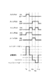
図4は、この実施形態に係る超音波診断装置の送信回路10の動作例を表すタイミングチャートである。このタイミングチャートは、各スイッチのオン・オフ状態と送信信号の電圧レベルとの関係を表す。
[Operation]
FIG. 4 is a timing chart showing an operation example of the
時点T1から時点T2までに亘り、切替部は、送信制御部11からの制御信号に基づいて、スイッチS1及びスイッチS4をオン状態とし、スイッチS2、スイッチS3、及びスイッチS5をオフ状態とする。それにより、接続経路は、第1の接続経路に切り替えられる。このとき、2次巻線L2には「k×(V11−V21)」の電圧が発生し、この電圧レベルの送信信号が超音波振動子20へ送られる。
From time T1 to time T2, the switching unit turns on the switch S1 and the switch S4 and turns off the switch S2, the switch S3, and the switch S5 based on the control signal from the
時点T2から時点T3までに亘り、切替部は、送信制御部11からの制御信号に基づいて、スイッチS1及びスイッチS5をオン状態とし、スイッチS2、スイッチS3、及びスイッチS4をオフ状態とする。それにより、接続経路は、第1のグランド経路に切り替えられる。このとき、2次巻線L2には「k×V11」の電圧が発生し、この電圧レベルの送信信号が超音波振動子20へ送られる。
From time T2 to time T3, the switching unit turns on the switch S1 and the switch S5 and turns off the switch S2, the switch S3, and the switch S4 based on the control signal from the
時点T3から時点T4までに亘り、切替部は、送信制御部11からの制御信号に基づいて、スイッチS3及びスイッチS4をオン状態とし、スイッチS1、スイッチS2、及びスイッチS5をオフ状態とする。それにより、接続経路は、第3の接続経路に切り替えられる。このとき、1次巻線L1の電圧はゼロであり、また、2次巻線L2の電圧はゼロである。それにより、ゼロ電圧の電圧レベルの送信信号が超音波振動子20へ送られる。
From time T3 to time T4, the switching unit turns on the switch S3 and the switch S4 and turns off the switch S1, the switch S2, and the switch S5 based on the control signal from the
時点T4から時点T5までに亘り、切替部は、送信制御部11からの制御信号に基づいて、スイッチS2及びスイッチS3をオン状態とし、スイッチS1、スイッチS4、及びスイッチS5をオフ状態とする。それにより、接続経路は、第2の接続経路に切り替えられる。このとき、2次巻線L2には「−k×(V11−V21)」の電圧が発生し、この電圧レベルの送信信号が超音波振動子20へ送られる。
From time T4 to time T5, the switching unit turns on the switch S2 and the switch S3 and turns off the switch S1, the switch S4, and the switch S5 based on the control signal from the
[効果]
この実施形態の超音波診断装置の効果について説明する。この実施形態の超音波診断装置は、トランスTRと、正電圧電源V1と、負電圧電源V2と、切替部とを有する。トランスTRは、1次巻線L1及び2次巻線L2を備え、2次巻線L2に発生した電圧に基づいて超音波振動子20を駆動する。切替部は、1次巻線L1と正電圧電源V1若しくは負電圧電源V2又はこれら双方との接続経路を、1次巻線L1の一端に正電圧電源V1を接続し1次巻線L1の他端に負電圧電源V2を接続する第1の接続経路、他端に正電圧電源V1を接続し一端に負電圧電源V2を接続する第2の接続経路、一端と他端とを短絡させる第3の接続経路、又は正電圧電源V1若しくは負電圧電源V2とグランドとを1次巻線L1を介して接続させるグランド接続経路に切り替えることによって、2次巻線L2に電圧を変化させて発生させる。また、グランド接続経路は、正電圧電源V1、1次巻線L1の一端、1次巻線L1の他端、グランドの順に対して電流が順方向となる第1のグランド接続経路を含む。このように、この実施形態の超音波診断装置は、1つの正電圧電源V1及び1つの負電圧電源V2により構成される送信回路10から多様な電圧レベルの送信信号を出力する。それにより、小さな規模の送信回路10から多様な電圧レベルの送信信号を超音波振動子20へ出力することができる超音波診断装置を提供することができる。
[effect]
The effect of the ultrasonic diagnostic apparatus of this embodiment will be described. The ultrasonic diagnostic apparatus of this embodiment includes a transformer TR, a positive voltage power supply V1, a negative voltage power supply V2, and a switching unit. The transformer TR includes a primary winding L1 and a secondary winding L2, and drives the
〈第1の実施形態の変形例1〉
[構成]
この変形例は、送信回路10の切替部と送信制御部11との構成が第1の実施形態に対して異なる。以下、異なる構成について説明する。図3及び図5は、この変形例の送信回路10の構成を表す回路図である。図3の端子TEと図5の端子TEとは、接続されている。
<
[Constitution]
In this modification, the configuration of the switching unit of the
切替部は、1次巻線L1と正電圧電源V1若しくは負電圧電源V2又はこれら双方との接続経路を、1次巻線L1の一端に正電圧電源V1を接続し1次巻線L1の他端に負電圧電源V2を接続する第1の接続経路、他端に正電圧電源V1を接続し一端に負電圧電源V2を接続する第2の接続経路、一端と他端とを短絡させる第3の接続経路、又は正電圧電源V1若しくは負電圧電源V2とグランドとを1次巻線L1を介して接続させるグランド接続経路に切り替えることによって、2次巻線L2に電圧を変化させて発生させる。グランド接続経路は、正電圧電源V1、1次巻線L1の他端、1次巻線L1の一端、グランドの順に対して電流が順方向となる第2のグランド接続経路を含む。 The switching unit connects the primary winding L1 and the positive voltage power source V1, the negative voltage power source V2, or both of them, connects the positive voltage power source V1 to one end of the primary winding L1, and other than the primary winding L1. A first connection path for connecting the negative voltage power supply V2 to one end, a second connection path for connecting the positive voltage power supply V1 to the other end and connecting the negative voltage power supply V2 to one end, and a third for short-circuiting one end and the other end. Is switched to a ground connection path for connecting the positive voltage power supply V1 or the negative voltage power supply V2 and the ground via the primary winding L1, and the voltage is generated in the secondary winding L2. The ground connection path includes a positive voltage power supply V1, the other end of the primary winding L1, one end of the primary winding L1, and a second ground connection path in which the current is forward with respect to the order of the ground.
切替部は、正電圧側スイッチと、負電圧側スイッチと、グランド側スイッチとを有する。正電圧側スイッチは、1次巻線L1の両端のそれぞれと正電圧電源V1との間に設けられたスイッチである。この変形例におけるスイッチS1とスイッチS2とが正電圧側スイッチに相当する。負電圧側スイッチは、1次巻線L1の両端のそれぞれと負電圧電源V2との間に設けられたスイッチである。この変形例におけるスイッチS3とスイッチS4とが負電圧側スイッチに相当する。グランド側スイッチは、1次巻線L1の一端とグランドとの間に設けられたスイッチである。この変形例におけるスイッチS6がグランド側スイッチに相当する。 The switching unit includes a positive voltage side switch, a negative voltage side switch, and a ground side switch. The positive voltage side switch is a switch provided between both ends of the primary winding L1 and the positive voltage power source V1. The switch S1 and the switch S2 in this modification correspond to a positive voltage side switch. The negative voltage side switch is a switch provided between each of both ends of the primary winding L1 and the negative voltage power source V2. The switches S3 and S4 in this modification correspond to negative voltage side switches. The ground side switch is a switch provided between one end of the primary winding L1 and the ground. The switch S6 in this modification corresponds to a ground side switch.
正電圧側スイッチ(スイッチS1、スイッチS2)は、オン時に正電圧電源V1側から1次巻線L1側へ電流が順方向となる電界効果トランジスタであり、いわゆるP型MOSFETである。負電圧側スイッチ(スイッチS3、スイッチS4)は、オン時に1次巻線L1側から負電圧電源V2側へ電流が順方向となる電界効果トランジスタあり、いわゆるN型MOSFETである。グランド側スイッチ(スイッチS6)は、第2のグランド接続経路において1次巻線L1の一端とグランドとの間に設けられる。また、グランド側スイッチは、オン時に1次巻線L1の一端側からグランド側へ電流が順方向となる電界効果トランジスタであり、いわゆるN型MOSFETである。 The positive voltage side switches (switch S1, switch S2) are field effect transistors in which the current is forward from the positive voltage power supply V1 side to the primary winding L1 side when they are turned on, and are so-called P-type MOSFETs. The negative voltage side switches (switch S3, switch S4) are field effect transistors in which the current is forward from the primary winding L1 side to the negative voltage power source V2 side when they are turned on, and are so-called N-type MOSFETs. The ground side switch (switch S6) is provided between one end of the primary winding L1 and the ground in the second ground connection path. The ground-side switch is a field effect transistor in which a current is forward from one end side of the primary winding L1 to the ground side when it is turned on, and is a so-called N-type MOSFET.
スイッチS1のソースには正電圧電源V1が接続され、スイッチS1のドレインには1次巻線L1の一端が接続される。また、スイッチS2のソースには正電圧電源V1が接続され、スイッチS2のドレインには1次巻線L1の他端が接続される。スイッチS3のドレインには1次巻線L1の一端が接続され、スイッチS3のソースには負電圧電源V2が接続される。スイッチS4のドレインには1次巻線L1の他端が接続され、スイッチS4のソースには負電圧電源V2が接続される。スイッチS6のドレインには1次巻線L1の一端が接続され、スイッチS6のソースにはグランドが接続される。 A positive voltage power supply V1 is connected to the source of the switch S1, and one end of the primary winding L1 is connected to the drain of the switch S1. A positive voltage power supply V1 is connected to the source of the switch S2, and the other end of the primary winding L1 is connected to the drain of the switch S2. One end of the primary winding L1 is connected to the drain of the switch S3, and the negative voltage power supply V2 is connected to the source of the switch S3. The other end of the primary winding L1 is connected to the drain of the switch S4, and the negative voltage power supply V2 is connected to the source of the switch S4. One end of the primary winding L1 is connected to the drain of the switch S6, and the ground is connected to the source of the switch S6.
切替部が、スイッチS1及びスイッチS4をオン状態とし、スイッチS2、スイッチS3、及びスイッチS6をオフ状態として、接続経路を第1の接続経路に切り替えたとき、2次巻線L2には「k×(V11−V21)」の電圧が発生し、この電圧レベルの送信信号が超音波振動子20へ送られる。また、切替部が、スイッチS3及びスイッチS4をオン状態とし、スイッチS1、スイッチS2、及びスイッチS6をオフ状態として、接続経路を第3の接続経路に切り替えたとき、1次巻線L1の電圧はゼロであり、また、2次巻線L2の電圧はゼロである。それにより、ゼロ電圧の電圧レベルの送信信号が超音波振動子20へ送られる。また、切替部が、スイッチS2及びスイッチS6をオン状態とし、スイッチS1、スイッチS3、及びスイッチS4をオフ状態として接続経路を第2のグランド接続経路に切り替えたとき、2次巻線L2には「−k×V11」の電圧が発生し、この電圧レベルの送信信号が超音波振動子20へ送られる。また、切替部が、スイッチS2及びスイッチS3をオン状態とし、スイッチS1、スイッチS4、及びスイッチS6をオフ状態として、接続経路を第2の接続経路に切り替えたとき、2次巻線L2には「−k×(V11−V21)」の電圧が発生し、この電圧レベルの送信信号が超音波振動子20へ送られる。なお、該送信信号は、接続経路が第1の接続経路であるときの送信信号に対して極性が反転した信号である。このような接続経路の切替によって、送信回路10は4レベルの電圧の送信信号を超音波振動子20へ出力することができる。
When the switching unit turns on the switch S1 and the switch S4, turns off the switch S2, the switch S3, and the switch S6 and switches the connection path to the first connection path, the secondary winding L2 has “k X (V11−V21) ”is generated, and a transmission signal of this voltage level is sent to the
なお、送信回路10は、第2のグランド接続経路の電界効果トランジスタ(スイッチS6)と1次巻線L1の一端との間に設けられ1次巻線L1の一端からグランドへの方向を順方向とするダイオードD6をさらに有してもよい。それにより、ダイオードD6は、スイッチS6を逆電圧から保護する。
The
送信制御部11は、切替部のスイッチS1のゲートG1、スイッチS2のゲートG2、スイッチS3のゲートG3、スイッチS4のゲートG4、及びスイッチS6のゲートG6のそれぞれへ制御信号を個別に出力し、スイッチS1、スイッチS2、スイッチS3、スイッチS4、及びスイッチS6を個別にオン・オフさせる。
The
[動作]
図6は、この変形例の超音波診断装置の送信回路10の動作例を表すタイミングチャートである。このタイミングチャートは、各スイッチのオン・オフ状態と送信信号の電圧レベルとの関係を表す。
[Operation]
FIG. 6 is a timing chart showing an operation example of the
時点T6から時点T7までに亘り、切替部は、送信制御部11からの制御信号に基づいて、スイッチS1及びスイッチS4をオン状態とし、スイッチS2、スイッチS3、及びスイッチS6をオフ状態とする。それにより、接続経路は、第1の接続経路に切り替えられる。このとき、2次巻線L2には「k×(V11−V21)」の電圧が発生し、この電圧レベルの送信信号が超音波振動子20へ送られる。
From time T6 to time T7, the switching unit turns on the switch S1 and the switch S4 and turns off the switch S2, the switch S3, and the switch S6 based on the control signal from the
時点T7から時点T8までに亘り、切替部は、送信制御部11からの制御信号に基づいて、スイッチS3及びスイッチS4をオン状態とし、スイッチS1、スイッチS2、及びスイッチS6をオフ状態とする。それにより、接続経路は、第3の接続経路に切り替えられる。このとき、1次巻線L1の電圧はゼロであり、また、2次巻線L2の電圧はゼロである。それにより、ゼロ電圧の電圧レベルの送信信号が超音波振動子20へ送られる。
From time T7 to time T8, the switching unit turns on the switch S3 and the switch S4 and turns off the switch S1, the switch S2, and the switch S6 based on the control signal from the
時点T8から時点T9までに亘り、切替部は、送信制御部11からの制御信号に基づいて、スイッチS2及びスイッチS6をオン状態とし、スイッチS1、スイッチS3、及びスイッチS4をオフ状態とする。それにより、接続経路は、第2のグランド接続経路に切り替えられる。このとき、2次巻線L2には「−k×V11」の電圧が発生し、この電圧レベルの送信信号が超音波振動子20へ送られる。
From time T8 to time T9, the switching unit turns on the switch S2 and the switch S6 and turns off the switch S1, the switch S3, and the switch S4 based on the control signal from the
時点T9から時点T10までに亘り、切替部は、送信制御部11からの制御信号に基づいて、スイッチS2及びスイッチS3をオン状態とし、スイッチS1、スイッチS4、及びスイッチS6をオフ状態とする。それにより、接続経路は、第2の接続経路に切り替えられる。このとき、2次巻線L2には「−k×(V11−V21)」の電圧が発生し、この電圧レベルの送信信号が超音波振動子20へ送られる。
From time T9 to time T10, the switching unit turns on the switches S2 and S3 and turns off the switches S1, S4, and S6 based on the control signal from the
[効果]
この変形例の超音波診断装置の効果について説明する。この変形例の超音波診断装置は、トランスTRと、正電圧電源V1と、負電圧電源V2と、切替部とを有する。トランスTRは、1次巻線L1及び2次巻線L2を備え、2次巻線L2に発生した電圧に基づいて超音波振動子20を駆動する。切替部は、1次巻線L1と正電圧電源V1若しくは負電圧電源V2又はこれら双方との接続経路を、1次巻線L1の一端に正電圧電源V1を接続し1次巻線L1の他端に負電圧電源V2を接続する第1の接続経路、1次巻線L1の他端に正電圧電源V1を接続し1次巻線L1の一端に負電圧電源V2を接続する第2の接続経路、1次巻線L1の一端と1次巻線L1の他端とを短絡させる第3の接続経路、又は正電圧電源V1若しくは負電圧電源V2とグランドとを1次巻線L1を介して接続させるグランド接続経路に切り替えることによって、2次巻線L2に電圧を変化させて発生させる。また、グランド接続経路は、正電圧電源V1、1次巻線L1の他端、1次巻線L1の一端、グランドの順に対して電流が順方向となる第2のグランド接続経路を含む。このように、この実施形態の超音波診断装置は、1つの正電圧電源V1及び1つの負電圧電源V2により構成される送信回路10から多様な電圧レベルの送信信号を出力する。それにより、小さな規模の送信回路10から多様な電圧レベルの送信信号を超音波振動子20へ出力することができる超音波診断装置を提供することができる。
[effect]
The effect of the ultrasonic diagnostic apparatus of this modification will be described. The ultrasonic diagnostic apparatus of this modification includes a transformer TR, a positive voltage power supply V1, a negative voltage power supply V2, and a switching unit. The transformer TR includes a primary winding L1 and a secondary winding L2, and drives the
〈第1の実施形態の変形例2〉
[構成]
この変形例は、送信回路10の切替部と送信制御部11との構成が、第1の実施形態と第1の実施形態の変形例1とに対して異なる。以下、異なる構成について説明する。図3及び図7は、この変形例の送信回路10の構成を表す回路図である。図3の端子TEと図7の端子TEとは、接続されている。
<
[Constitution]
In this modification, the configurations of the switching unit and the
切替部は、1次巻線L1と正電圧電源V1若しくは負電圧電源V2又はこれら双方との接続経路を、1次巻線L1の一端に正電圧電源V1を接続し1次巻線L1の他端に負電圧電源V2を接続する第1の接続経路、1次巻線L1の他端に正電圧電源V1を接続し1次巻線L1の一端に負電圧電源V2を接続する第2の接続経路、1次巻線L1の一端と1次巻線L1の他端とを短絡させる第3の接続経路、又は正電圧電源V1若しくは負電圧電源V2とグランドとを1次巻線L1を介して接続させるグランド接続経路に切り替えることによって、2次巻線L2に電圧を変化させて発生させる。グランド接続経路は、グランド、1次巻線L1の一端、1次巻線L1の他端、負電圧電源V2の順に対して電流が順方向となる第3のグランド接続経路を含む。 The switching unit connects the primary winding L1 and the positive voltage power source V1, the negative voltage power source V2, or both of them, connects the positive voltage power source V1 to one end of the primary winding L1, and other than the primary winding L1. A first connection path for connecting the negative voltage power supply V2 to the end, a second connection for connecting the positive voltage power supply V1 to the other end of the primary winding L1 and connecting the negative voltage power supply V2 to one end of the primary winding L1 Path, a third connection path for short-circuiting one end of the primary winding L1 and the other end of the primary winding L1, or a positive voltage power supply V1 or a negative voltage power supply V2 and the ground via the primary winding L1. By switching to the ground connection path to be connected, the voltage is generated in the secondary winding L2. The ground connection path includes a third ground connection path in which the current is forward with respect to the order of the ground, one end of the primary winding L1, the other end of the primary winding L1, and the negative voltage power supply V2.
切替部は、正電圧側スイッチと、負電圧側スイッチと、グランド側スイッチとを有する。正電圧側スイッチは、1次巻線L1の両端のそれぞれと正電圧電源V1との間に設けられたスイッチである。この変形例におけるスイッチS1とスイッチS2とが正電圧側スイッチに相当する。負電圧側スイッチは、1次巻線L1の両端のそれぞれと負電圧電源V2との間に設けられたスイッチである。この変形例におけるスイッチS3とスイッチS4とが負電圧側スイッチに相当する。グランド側スイッチは、1次巻線L1の一端とグランドとの間に設けられたスイッチである。この変形例におけるスイッチS7がグランド側スイッチに相当する。 The switching unit includes a positive voltage side switch, a negative voltage side switch, and a ground side switch. The positive voltage side switch is a switch provided between both ends of the primary winding L1 and the positive voltage power source V1. The switch S1 and the switch S2 in this modification correspond to a positive voltage side switch. The negative voltage side switch is a switch provided between each of both ends of the primary winding L1 and the negative voltage power source V2. The switches S3 and S4 in this modification correspond to negative voltage side switches. The ground side switch is a switch provided between one end of the primary winding L1 and the ground. The switch S7 in this modification corresponds to a ground side switch.
正電圧側スイッチ(スイッチS1、スイッチS2)は、オン時に正電圧電源V1側から1次巻線L1側へ電流が順方向となる電界効果トランジスタであり、いわゆるP型MOSFETである。負電圧側スイッチ(スイッチS3、スイッチS4)は、オン時に1次巻線L1側から負電圧電源V2側へ電流が順方向となる電界効果トランジスタあり、いわゆるN型MOSFETである。グランド側スイッチ(スイッチS7)は、第3のグランド接続経路において1次巻線L1の一端とグランドとの間に設けられる。また、グランド側スイッチは、オン時にグランド側から1次巻線L1の一端側へ電流が順方向となる電界効果トランジスタであり、いわゆるP型MOSFETである。 The positive voltage side switches (switch S1, switch S2) are field effect transistors in which the current is forward from the positive voltage power supply V1 side to the primary winding L1 side when they are turned on, and are so-called P-type MOSFETs. The negative voltage side switches (switch S3, switch S4) are field effect transistors in which the current is forward from the primary winding L1 side to the negative voltage power source V2 side when they are turned on, and are so-called N-type MOSFETs. The ground side switch (switch S7) is provided between one end of the primary winding L1 and the ground in the third ground connection path. The ground side switch is a field effect transistor in which a current is forward from the ground side to one end side of the primary winding L1 when turned on, and is a so-called P-type MOSFET.
スイッチS1のソースには正電圧電源V1が接続され、スイッチS1のドレインには1次巻線L1の一端が接続される。また、スイッチS2のソースには正電圧電源V1が接続され、スイッチS2のドレインには1次巻線L1の他端が接続される。スイッチS3のドレインには1次巻線L1の一端が接続され、スイッチS3のソースには負電圧電源V2が接続される。スイッチS4のドレインには1次巻線L1の他端が接続され、スイッチS4のソースには負電圧電源V2が接続される。スイッチS7のドレインには1次巻線L1の一端が接続され、スイッチS7のソースにはグランドが接続される。 A positive voltage power supply V1 is connected to the source of the switch S1, and one end of the primary winding L1 is connected to the drain of the switch S1. A positive voltage power supply V1 is connected to the source of the switch S2, and the other end of the primary winding L1 is connected to the drain of the switch S2. One end of the primary winding L1 is connected to the drain of the switch S3, and the negative voltage power supply V2 is connected to the source of the switch S3. The other end of the primary winding L1 is connected to the drain of the switch S4, and the negative voltage power supply V2 is connected to the source of the switch S4. One end of the primary winding L1 is connected to the drain of the switch S7, and the ground is connected to the source of the switch S7.
切替部が、スイッチS1及びスイッチS4をオン状態とし、スイッチS2、スイッチS3、及びスイッチS6をオフ状態として、接続経路を第1の接続経路に切り替えたとき、2次巻線L2には「k×(V11−V21)」の電圧が発生し、この電圧レベルの送信信号が超音波振動子20へ送られる。また、切替部が、スイッチS4及びスイッチS7をオン状態とし、スイッチS1、スイッチS2、及びスイッチS3をオフ状態として、接続経路を第3のグランド接続経路に切り替えたとき、2次巻線L2には「−k×V21」の電圧が発生し、この電圧レベルの送信信号が超音波振動子20へ送られる。また、切替部が、スイッチS3及びスイッチS4をオン状態とし、スイッチS1、スイッチS2、及びスイッチS7をオフ状態として、接続経路を第3の接続経路に切り替えたとき、2次巻線L2の電圧はゼロであり、ゼロ電圧の電圧レベルの送信信号が超音波振動子20へ送られる。また、切替部が、スイッチS3及びスイッチS4をオン状態とし、スイッチS1、スイッチS2、及びスイッチS7をオフ状態として、接続経路を第3の接続経路に切り替えたとき、1次巻線L1の電圧はゼロであり、また、2次巻線L2の電圧はゼロである。それにより、ゼロ電圧の電圧レベルの送信信号が超音波振動子20へ送られる。また、切替部が、スイッチS2及びスイッチS3をオン状態とし、スイッチS1、スイッチS4、及びスイッチS7をオフ状態として、接続経路を第2の接続経路に切り替えたとき、2次巻線L2には「−k×(V11−V21)」の電圧が発生し、この電圧レベルの送信信号が超音波振動子20へ送られる。なお、該送信信号は、接続経路が第1の接続経路であるときの送信信号に対して極性が反転した信号である。このような接続経路の切替によって、送信回路10は4レベルの電圧の送信信号を超音波振動子20へ出力することができる。
When the switching unit turns on the switch S1 and the switch S4, turns off the switch S2, the switch S3, and the switch S6 and switches the connection path to the first connection path, the secondary winding L2 has “k X (V11−V21) ”is generated, and a transmission signal of this voltage level is sent to the
なお、送信回路10は、第3のグランド接続経路の電界効果トランジスタ(スイッチS7)と1次巻線L1の一端との間に設けられグランドから1次巻線L1の一端への方向を順方向とするダイオードD7をさらに有してもよい。それにより、ダイオードD7は、スイッチS7を逆電圧から保護する。
The
送信制御部11は、切替部のスイッチS1のゲートG1、スイッチS2のゲートG2、スイッチS3のゲートG3、スイッチS4のゲートG4、及びスイッチS7のゲートG7のそれぞれへ制御信号を個別に出力し、スイッチS1、スイッチS2、スイッチS3、スイッチS4、及びスイッチS7を個別にオン・オフさせる。
The
[動作]
図8は、この変形例の超音波診断装置の送信回路10の動作例を表すタイミングチャートである。このタイミングチャートは、各スイッチのオン・オフ状態と送信信号の電圧レベルとの関係を表す。
[Operation]
FIG. 8 is a timing chart showing an operation example of the
時点T11から時点T12までに亘り、切替部は、送信制御部11からの制御信号に基づいて、スイッチS1及びスイッチS4をオン状態とし、スイッチS2、スイッチS3、及びスイッチS7をオフ状態とする。それにより、接続経路は、第1の接続経路に切り替えられる。このとき、2次巻線L2には「k×(V11−V21)」の電圧が発生し、この電圧レベルの送信信号が超音波振動子20へ送られる。
From time T11 to time T12, the switching unit turns on the switches S1 and S4 and turns off the switches S2, S3, and S7 based on the control signal from the
時点T12から時点T13までに亘り、切替部は、送信制御部11からの制御信号に基づいて、スイッチS4及びスイッチS7をオン状態とし、スイッチS1、スイッチS2、及びスイッチS3をオフ状態とする。それにより、接続経路は、第3のグランド接続経路に切り替えられる。このとき、2次巻線L2には「−k×V21」の電圧が発生し、この電圧レベルの送信信号が超音波振動子20へ送られる。
From time T12 to time T13, the switching unit turns on the switch S4 and the switch S7 and turns off the switch S1, the switch S2, and the switch S3 based on the control signal from the
時点T13から時点T14までに亘り、切替部は、送信制御部11からの制御信号に基づいて、スイッチS3及びスイッチS4をオン状態とし、スイッチS1、スイッチS2、及びスイッチS7をオフ状態とする。それにより、接続経路は、第3の接続経路に切り替えられる。このとき、1次巻線L1の電圧はゼロであり、また、2次巻線L2の電圧はゼロである。それにより、ゼロ電圧の電圧レベルの送信信号が超音波振動子20へ送られる。
From time T13 to time T14, the switching unit turns on the switch S3 and the switch S4 and turns off the switch S1, the switch S2, and the switch S7 based on the control signal from the
時点T14から時点T15までに亘り、切替部は、送信制御部11からの制御信号に基づいて、スイッチS2及びスイッチS3をオン状態とし、スイッチS1、スイッチS4、及びスイッチS7をオフ状態とする。それにより、接続経路は、第2の接続経路に切り替えられる。このとき、2次巻線L2には「−k×(V11−V21)」の電圧が発生し、この電圧レベルの送信信号が超音波振動子20へ送られる。
From time T14 to time T15, the switching unit turns on the switch S2 and the switch S3 and turns off the switch S1, the switch S4, and the switch S7 based on the control signal from the
[効果]
この変形例の超音波診断装置の効果について説明する。この変形例の超音波診断装置は、トランスTRと、正電圧電源V1と、負電圧電源V2と、切替部とを有する。トランスTRは、1次巻線L1及び2次巻線L2を備え、2次巻線L2に発生した電圧に基づいて超音波振動子20を駆動する。切替部は、1次巻線L1と正電圧電源V1若しくは負電圧電源V2又はこれら双方との接続経路を、1次巻線L1の一端に正電圧電源V1を接続し1次巻線L1の他端に負電圧電源V2を接続する第1の接続経路、1次巻線L1の他端に正電圧電源V1を接続し1次巻線L1の一端に負電圧電源V2を接続する第2の接続経路、1次巻線L1の一端と1次巻線L1の他端とを短絡させる第3の接続経路、又は正電圧電源V1若しくは負電圧電源V2とグランドとを1次巻線L1を介して接続させるグランド接続経路に切り替えることによって、2次巻線L2に電圧を変化させて発生させる。また、グランド接続経路は、グランド、1次巻線L1の一端、1次巻線L1の他端、負電圧電源V2の順に対して電流が順方向となる第3のグランド接続経路を含む。このように、この実施形態の超音波診断装置は、1つの正電圧電源V1及び1つの負電圧電源V2により構成される送信回路10から多様な電圧レベルの送信信号を出力する。それにより、小さな規模の送信回路10から多様な電圧レベルの送信信号を超音波振動子20へ出力することができる超音波診断装置を提供することができる。
[effect]
The effect of the ultrasonic diagnostic apparatus of this modification will be described. The ultrasonic diagnostic apparatus of this modification includes a transformer TR, a positive voltage power supply V1, a negative voltage power supply V2, and a switching unit. The transformer TR includes a primary winding L1 and a secondary winding L2, and drives the
〈第1の実施形態の変形例3〉
[構成]
この変形例の超音波診断装置は、送信回路10の切替部と送信制御部11との構成が、第1の実施形態と第1の実施形態の変形例1と第1の実施形態の変形例2とに対して異なる。以下、異なる構成について説明する。図3及び図9は、この変形例の送信回路10の構成を表す回路図である。図3の端子TEと図9の端子TEとは、接続されている。
<
[Constitution]
In the ultrasonic diagnostic apparatus of this modification, the configuration of the switching unit and the
切替部は、1次巻線L1と正電圧電源V1若しくは負電圧電源V2又はこれら双方との接続経路を、1次巻線L1の一端に正電圧電源V1を接続し1次巻線L1の他端に負電圧電源V2を接続する第1の接続経路、1次巻線L1の他端に正電圧電源V1を接続し1次巻線L1の一端に負電圧電源V2を接続する第2の接続経路、1次巻線L1の一端と1次巻線L1の他端とを短絡させる第3の接続経路、又は正電圧電源V1若しくは負電圧電源V2とグランドとを1次巻線L1を介して接続させるグランド接続経路に切り替えることによって、2次巻線L2に電圧を変化させて発生させる。グランド接続経路は、グランド、1次巻線L1の他端、1次巻線L1の一端、負電圧電源V2の順に対して電流が順方向となる第4のグランド接続経路を含む。 The switching unit connects the primary winding L1 and the positive voltage power source V1, the negative voltage power source V2, or both of them, connects the positive voltage power source V1 to one end of the primary winding L1, and other than the primary winding L1. A first connection path for connecting the negative voltage power supply V2 to the end, a second connection for connecting the positive voltage power supply V1 to the other end of the primary winding L1 and connecting the negative voltage power supply V2 to one end of the primary winding L1 Path, a third connection path for short-circuiting one end of the primary winding L1 and the other end of the primary winding L1, or a positive voltage power supply V1 or a negative voltage power supply V2 and the ground via the primary winding L1. By switching to the ground connection path to be connected, the voltage is generated in the secondary winding L2. The ground connection path includes a fourth ground connection path in which the current is forward with respect to the order of the ground, the other end of the primary winding L1, the one end of the primary winding L1, and the negative voltage power supply V2.
切替部は、正電圧側スイッチと、負電圧側スイッチと、グランド側スイッチとを有する。正電圧側スイッチは、1次巻線L1の両端のそれぞれと正電圧電源V1との間に設けられたスイッチである。この変形例におけるスイッチS1とスイッチS2とが正電圧側スイッチに相当する。負電圧側スイッチは、1次巻線L1の両端のそれぞれと負電圧電源V2との間に設けられたスイッチである。この変形例におけるスイッチS3とスイッチS4とが負電圧側スイッチに相当する。グランド側スイッチは、1次巻線L1の他端とグランドとの間に設けられたスイッチである。この変形例におけるスイッチS8がグランド側スイッチに相当する。 The switching unit includes a positive voltage side switch, a negative voltage side switch, and a ground side switch. The positive voltage side switch is a switch provided between both ends of the primary winding L1 and the positive voltage power source V1. The switch S1 and the switch S2 in this modification correspond to a positive voltage side switch. The negative voltage side switch is a switch provided between each of both ends of the primary winding L1 and the negative voltage power source V2. The switches S3 and S4 in this modification correspond to negative voltage side switches. The ground side switch is a switch provided between the other end of the primary winding L1 and the ground. The switch S8 in this modification corresponds to a ground side switch.
正電圧側スイッチ(スイッチS1、スイッチS2)は、オン時に正電圧電源V1側から1次巻線L1側へ電流が順方向となる電界効果トランジスタであり、いわゆるP型MOSFETである。負電圧側スイッチ(スイッチS3、スイッチS4)は、オン時に1次巻線L1側から負電圧電源V2側へ電流が順方向となる電界効果トランジスタあり、いわゆるN型MOSFETである。グランド側スイッチ(スイッチS8)は、第4のグランド接続経路において1次巻線L1の他端とグランドとの間に設けられる。グランド側スイッチは、オン時にグランド側から1次巻線L1の他端側へ電流が順方向となる電界効果トランジスタであり、いわゆるP型MOSFETである。 The positive voltage side switches (switch S1, switch S2) are field effect transistors in which the current is forward from the positive voltage power supply V1 side to the primary winding L1 side when they are turned on, and are so-called P-type MOSFETs. The negative voltage side switches (switch S3, switch S4) are field effect transistors in which the current is forward from the primary winding L1 side to the negative voltage power source V2 side when they are turned on, and are so-called N-type MOSFETs. The ground side switch (switch S8) is provided between the other end of the primary winding L1 and the ground in the fourth ground connection path. The ground side switch is a field effect transistor in which a current flows in a forward direction from the ground side to the other end side of the primary winding L1 when turned on, and is a so-called P-type MOSFET.
スイッチS1のソースには正電圧電源V1が接続され、スイッチS1のドレインには1次巻線L1の一端が接続される。また、スイッチS2のソースには正電圧電源V1が接続され、スイッチS2のドレインには1次巻線L1の他端が接続される。スイッチS3のドレインには1次巻線L1の一端が接続され、スイッチS3のソースには負電圧電源V2が接続される。スイッチS4のドレインには1次巻線L1の他端が接続され、スイッチS4のソースには負電圧電源V2が接続される。スイッチS8のドレインには1次巻線L1の他端が接続され、スイッチS8のソースにはグランドが接続される。 A positive voltage power supply V1 is connected to the source of the switch S1, and one end of the primary winding L1 is connected to the drain of the switch S1. A positive voltage power supply V1 is connected to the source of the switch S2, and the other end of the primary winding L1 is connected to the drain of the switch S2. One end of the primary winding L1 is connected to the drain of the switch S3, and the negative voltage power supply V2 is connected to the source of the switch S3. The other end of the primary winding L1 is connected to the drain of the switch S4, and the negative voltage power supply V2 is connected to the source of the switch S4. The other end of the primary winding L1 is connected to the drain of the switch S8, and the ground is connected to the source of the switch S8.
切替部が、スイッチS1及びスイッチS4をオン状態とし、スイッチS2、スイッチS3、及びスイッチS8をオフ状態として、接続経路を第1の接続経路に切り替えたとき、2次巻線L2には「k×(V11−V21)」の電圧が発生し、この電圧レベルの送信信号が超音波振動子20へ送られる。また、切替部が、スイッチS3及びスイッチS4をオン状態とし、スイッチS1、スイッチS2、及びスイッチS8をオフ状態として、接続経路を第3の接続経路に切り替えたとき、1次巻線L1の電圧はゼロであり、また、2次巻線L2の電圧はゼロである。それにより、ゼロ電圧の電圧レベルの送信信号が超音波振動子20へ送られる。また、切替部が、スイッチS3及びスイッチS8をオン状態とし、スイッチS1、スイッチS2、及びスイッチS4をオフ状態として、接続経路を第4のグランド接続経路に切り替えたとき、2次巻線L2には「k×V21」の電圧が発生し、この電圧レベルの送信信号が超音波振動子20へ送られる。また、切替部が、スイッチS2及びスイッチS3をオン状態とし、スイッチS1、スイッチS4、及びスイッチS8をオフ状態として、接続経路を第2の接続経路に切り替えたとき、2次巻線L2には「−k×(V11−V21)」の電圧が発生し、この電圧レベルの送信信号が超音波振動子20へ送られる。なお、該送信信号は、接続経路が第1の接続経路であるときの送信信号に対して極性が反転した信号である。このような接続経路の切替によって、送信回路10は4レベルの電圧の送信信号を超音波振動子20へ出力することができる。
When the switching unit turns on the switch S1 and the switch S4, turns off the switch S2, the switch S3, and the switch S8 and switches the connection path to the first connection path, the secondary winding L2 has “k X (V11−V21) ”is generated, and a transmission signal of this voltage level is sent to the
なお、送信回路10は、第4のグランド接続経路の電界効果トランジスタ(スイッチS8)と1次巻線L1の他端との間に設けられグランドから1次巻線L1の他端への方向を順方向とするダイオードD8をさらに有してもよい。それにより、スイッチS8を逆電圧から保護する。
The
送信制御部11は、切替部のスイッチS1のゲートG1、スイッチS2のゲートG2、スイッチS3のゲートG3、スイッチS4のゲートG4、及びスイッチS8のゲートG8のそれぞれへ制御信号を個別に出力し、スイッチS1、スイッチS2、スイッチS3、スイッチS4、及びスイッチS8を個別にオン・オフさせる。
The
[動作]
図10は、この変形例の超音波診断装置の送信回路10の動作例を表すタイミングチャートである。このタイミングチャートは、各スイッチのオン・オフ状態と送信信号の電圧レベルとの関係を表す。
[Operation]
FIG. 10 is a timing chart illustrating an operation example of the
時点T16から時点T17までに亘り、切替部は、送信制御部11からの制御信号に基づいて、スイッチS1及びスイッチS4をオン状態とし、スイッチS2、スイッチS3、及びスイッチS8をオフ状態とする。それにより、接続経路は、第1の接続経路に切り替えられる。このとき、2次巻線L2には「k×(V11−V21)」の電圧が発生し、この電圧レベルの送信信号が超音波振動子20へ送られる。
From time T16 to time T17, the switching unit turns on the switch S1 and the switch S4 and turns off the switch S2, the switch S3, and the switch S8 based on the control signal from the
時点T17から時点T18までに亘り、切替部は、送信制御部11からの制御信号に基づいて、スイッチS3及びスイッチS4をオン状態とし、スイッチS1、スイッチS2、及びスイッチS8をオフ状態とする。それにより、接続経路は、第3の接続経路に切り替えられる。このとき、1次巻線L1の電圧はゼロであり、また、2次巻線L2の電圧はゼロである。それにより、ゼロ電圧の電圧レベルの送信信号が超音波振動子20へ送られる。
From time T17 to time T18, the switching unit turns on the switch S3 and the switch S4 and turns off the switch S1, the switch S2, and the switch S8 based on the control signal from the
時点T18から時点T19までに亘り、切替部は、送信制御部11からの制御信号に基づいて、スイッチS3及びスイッチS8をオン状態とし、スイッチS1、スイッチS2、及びスイッチS4をオフ状態とする。それにより、接続経路は、第4のグランド接続経路に切り替えられる。このとき、2次巻線L2には「k×V21」の電圧が発生し、この電圧レベルの送信信号が超音波振動子20へ送られる。
From time T18 to time T19, the switching unit turns on the switch S3 and the switch S8 and turns off the switch S1, the switch S2, and the switch S4 based on the control signal from the
時点T19から時点T20までに亘り、切替部は、送信制御部11からの制御信号に基づいて、スイッチS2及びスイッチS3をオン状態とし、スイッチS1、スイッチS4、及びスイッチS8をオフ状態とする。それにより、接続経路は、第2の接続経路に切り替えられる。このとき、2次巻線L2には「−k×(V11−V21)」の電圧が発生し、この電圧レベルの送信信号が超音波振動子20へ送られる。
From time T19 to time T20, the switching unit turns on the switch S2 and the switch S3 and turns off the switch S1, the switch S4, and the switch S8 based on the control signal from the
[効果]
この変形例の超音波診断装置の効果について説明する。この変形例の超音波診断装置は、トランスTRと、正電圧電源V1と、負電圧電源V2と、切替部とを有する。トランスTRは、1次巻線L1及び2次巻線L2を備え、2次巻線L2に発生した電圧に基づいて超音波振動子20を駆動する。切替部は、1次巻線L1と正電圧電源V1若しくは負電圧電源V2又はこれら双方との接続経路を、1次巻線L1の一端に正電圧電源V1を接続し1次巻線L1の他端に負電圧電源V2を接続する第1の接続経路、1次巻線L1の他端に正電圧電源V1を接続し1次巻線L1の一端に負電圧電源V2を接続する第2の接続経路、1次巻線L1の一端と1次巻線L1の他端とを短絡させる第3の接続経路、又は正電圧電源V1若しくは負電圧電源V2とグランドとを1次巻線L1を介して接続させるグランド接続経路に切り替えることによって、2次巻線L2に電圧を変化させて発生させる。また、グランド接続経路は、グランド、1次巻線L1の他端、1次巻線L1の一端、負電圧電源V2の順に対して電流が順方向となる第4のグランド接続経路を含む。このように、この実施形態の超音波診断装置は、1つの正電圧電源V1及び1つの負電圧電源V2により構成される送信回路10から多様な電圧レベルの送信信号を出力する。それにより、小さな規模の送信回路10から多様な電圧レベルの送信信号を超音波振動子20へ出力することができる超音波診断装置を提供することができる。
[effect]
The effect of the ultrasonic diagnostic apparatus of this modification will be described. The ultrasonic diagnostic apparatus of this modification includes a transformer TR, a positive voltage power supply V1, a negative voltage power supply V2, and a switching unit. The transformer TR includes a primary winding L1 and a secondary winding L2, and drives the
なお、第1の実施形態と前述した変形例との間で回路構成を参酌し、グランド接続経路が、第1のグランド接続経路、第2のグランド接続経路、第3のグランド接続経路、第4のグランド接続経路の任意の組み合わせを含んでもよい。以下、第2の実施形態の説明において、グランド接続経路が、第1のグランド接続経路、第2のグランド接続経路、第3のグランド接続経路、及び第4のグランド接続経路を含む実施形態について説明する。 The circuit configuration is considered between the first embodiment and the modification described above, and the ground connection paths are the first ground connection path, the second ground connection path, the third ground connection path, and the fourth. Any combination of the ground connection paths may be included. Hereinafter, in the description of the second embodiment, an embodiment will be described in which the ground connection path includes a first ground connection path, a second ground connection path, a third ground connection path, and a fourth ground connection path. To do.
〈第2の実施形態〉
第2の実施形態の超音波診断装置は、送信回路10の切替部と送信制御部11との構成が、第1の実施形態と第1の実施形態の変形例1と第1の実施形態の変形例2と第1の実施形態の変形例3とに対して異なる。以下、異なる構成について説明する。図3及び図11は、この実施形態の送信回路10の構成を表す回路図である。図3の端子TEと図9の端子TEとは、接続されている。
<Second Embodiment>
In the ultrasonic diagnostic apparatus of the second embodiment, the configuration of the switching unit and the
切替部は、1次巻線L1と正電圧電源V1若しくは負電圧電源V2又はこれら双方との接続経路を、1次巻線L1の一端に正電圧電源V1を接続し1次巻線L1の他端に負電圧電源V2を接続する第1の接続経路、1次巻線L1の他端に正電圧電源V1を接続し1次巻線L1の一端に負電圧電源V2を接続する第2の接続経路、1次巻線L1の一端と1次巻線L1の他端とを短絡させる第3の接続経路、又は正電圧電源V1若しくは負電圧電源V2とグランドとを1次巻線L1を介して接続させるグランド接続経路に切り替えることによって、2次巻線L2に電圧を変化させて発生させる。グランド接続経路は、正電圧電源V1、1次巻線L1の一端、1次巻線L1の他端、グランドの順に対して電流が順方向となる第1のグランド接続経路、正電圧電源V1、1次巻線L1の他端、1次巻線L1の一端、グランドの順に対して電流が順方向となる第2のグランド接続経路、グランド、1次巻線L1の一端、1次巻線L1の他端、負電圧電源V2の順に対して電流が順方向となる第3のグランド接続経路、及びグランド、1次巻線L1の他端、1次巻線L1の一端、負電圧電源V2の順に対して電流が順方向となる第4のグランド接続経路を含む。 The switching unit connects the primary winding L1 and the positive voltage power source V1, the negative voltage power source V2, or both of them, connects the positive voltage power source V1 to one end of the primary winding L1, and other than the primary winding L1. A first connection path for connecting the negative voltage power supply V2 to the end, a second connection for connecting the positive voltage power supply V1 to the other end of the primary winding L1 and connecting the negative voltage power supply V2 to one end of the primary winding L1 Path, a third connection path for short-circuiting one end of the primary winding L1 and the other end of the primary winding L1, or a positive voltage power supply V1 or a negative voltage power supply V2 and the ground via the primary winding L1. By switching to the ground connection path to be connected, the voltage is generated in the secondary winding L2. The ground connection path includes a positive voltage power supply V1, one end of the primary winding L1, the other end of the primary winding L1, a first ground connection path in which the current is forward with respect to the order of the ground, the positive voltage power supply V1, The other end of the primary winding L1, one end of the primary winding L1, a second ground connection path in which the current is forward with respect to the order of the ground, the ground, one end of the primary winding L1, and the primary winding L1 , The third ground connection path in which the current is in the forward direction with respect to the order of the negative voltage power source V2, the ground, the other end of the primary winding L1, the one end of the primary winding L1, and the negative voltage power source V2. A fourth ground connection path in which the current is forward with respect to the forward direction is included.
切替部は、正電圧側スイッチと、負電圧側スイッチと、グランド側スイッチとを有する。正電圧側スイッチは、1次巻線L1の両端のそれぞれと正電圧電源V1との間に設けられたスイッチである。この実施形態におけるスイッチS1とスイッチS2とが正電圧側スイッチに相当する。負電圧側スイッチは、1次巻線L1の両端のそれぞれと負電圧電源V2との間に設けられたスイッチである。この実施形態におけるスイッチS3とスイッチS4とが負電圧側スイッチに相当する。グランド側スイッチは、1次巻線L1の他端とグランドとの間に設けられたスイッチS5及びスイッチS8、並びに1次巻線L1の一端とグランドとの間に設けられたスイッチS6及びスイッチS7を含む。なお、スイッチS5とスイッチS8とは、1次巻線L1に対して並列に設けられる。また、スイッチS6とスイッチS7とは1次巻線L1に対して並列に設けられる。 The switching unit includes a positive voltage side switch, a negative voltage side switch, and a ground side switch. The positive voltage side switch is a switch provided between both ends of the primary winding L1 and the positive voltage power source V1. The switch S1 and the switch S2 in this embodiment correspond to a positive voltage side switch. The negative voltage side switch is a switch provided between each of both ends of the primary winding L1 and the negative voltage power source V2. In this embodiment, the switch S3 and the switch S4 correspond to a negative voltage side switch. The ground side switches are switches S5 and S8 provided between the other end of the primary winding L1 and the ground, and switches S6 and S7 provided between one end of the primary winding L1 and the ground. including. Note that the switch S5 and the switch S8 are provided in parallel to the primary winding L1. Further, the switch S6 and the switch S7 are provided in parallel with the primary winding L1.
正電圧側スイッチ(スイッチS1、スイッチS2)は、オン時に正電圧電源V1側から1次巻線L1側へ電流が順方向となる電界効果トランジスタであり、いわゆるP型MOSFETである。負電圧側スイッチ(スイッチS3、スイッチS4)は、オン時に1次巻線L1側から負電圧電源V2側へ電流が順方向となる電界効果トランジスタあり、いわゆるN型MOSFETである。 The positive voltage side switches (switch S1, switch S2) are field effect transistors in which the current is forward from the positive voltage power supply V1 side to the primary winding L1 side when they are turned on, and are so-called P-type MOSFETs. The negative voltage side switches (switch S3, switch S4) are field effect transistors in which the current is forward from the primary winding L1 side to the negative voltage power source V2 side when they are turned on, and are so-called N-type MOSFETs.
スイッチS5は、第1のグランド接続経路において1次巻線L1の他端とグランドとの間に設けられる。また、スイッチS5は、オン時に1次巻線L1の他端側からグランド側へ電流が順方向となる電界効果トランジスタであり、いわゆるN型MOSFETである。スイッチS6は、第2のグランド接続経路において1次巻線L1の一端とグランドとの間に設けられる。また、スイッチS6は、オン時に1次巻線L1の一端側からグランド側へ電流が順方向となる電界効果トランジスタであり、いわゆるN型MOSFETである。スイッチS7は、第3のグランド接続経路において1次巻線L1の一端とグランドとの間に設けられる。また、スイッチS7は、オン時にグランド側から1次巻線L1の一端側へ電流が順方向となる電界効果トランジスタであり、いわゆるP型MOSFETである。スイッチS8は、第4のグランド接続経路において1次巻線L1の他端とグランドとの間に設けられる。スイッチS8は、オン時にグランド側から1次巻線L1の他端側へ電流が順方向となる電界効果トランジスタであり、いわゆるP型MOSFETである。 The switch S5 is provided between the other end of the primary winding L1 and the ground in the first ground connection path. The switch S5 is a field effect transistor in which a current is forward from the other end side of the primary winding L1 to the ground side when turned on, and is a so-called N-type MOSFET. The switch S6 is provided between one end of the primary winding L1 and the ground in the second ground connection path. The switch S6 is a field effect transistor in which a current is forward from one end side of the primary winding L1 to the ground side when it is turned on, and is a so-called N-type MOSFET. The switch S7 is provided between one end of the primary winding L1 and the ground in the third ground connection path. The switch S7 is a field effect transistor in which a current is forward from the ground side to one end side of the primary winding L1 when it is turned on, and is a so-called P-type MOSFET. The switch S8 is provided between the other end of the primary winding L1 and the ground in the fourth ground connection path. The switch S8 is a so-called P-type MOSFET that is a field effect transistor in which a current is forward from the ground side to the other end side of the primary winding L1 when turned on.
スイッチS1のソースには正電圧電源V1が接続され、スイッチS1のドレインには1次巻線L1の一端が接続される。また、スイッチS2のソースには正電圧電源V1が接続され、スイッチS2のドレインには1次巻線L1の他端が接続される。スイッチS3のドレインには1次巻線L1の一端が接続され、スイッチS3のソースには負電圧電源V2が接続される。スイッチS4のドレインには1次巻線L1の他端が接続され、スイッチS4のソースには負電圧電源V2が接続される。 A positive voltage power supply V1 is connected to the source of the switch S1, and one end of the primary winding L1 is connected to the drain of the switch S1. A positive voltage power supply V1 is connected to the source of the switch S2, and the other end of the primary winding L1 is connected to the drain of the switch S2. One end of the primary winding L1 is connected to the drain of the switch S3, and the negative voltage power supply V2 is connected to the source of the switch S3. The other end of the primary winding L1 is connected to the drain of the switch S4, and the negative voltage power supply V2 is connected to the source of the switch S4.
スイッチS5のドレインには1次巻線L1の他端が接続され、スイッチS5のソースにはグランドが接続される。スイッチS6のドレインには1次巻線L1の一端が接続され、スイッチS6のソースにはグランドが接続される。スイッチS7のドレインには1次巻線L1の一端が接続され、スイッチS7のソースにはグランドが接続される。スイッチS8のドレインには1次巻線L1の他端が接続され、スイッチS8のソースにはグランドが接続される。 The other end of the primary winding L1 is connected to the drain of the switch S5, and the ground is connected to the source of the switch S5. One end of the primary winding L1 is connected to the drain of the switch S6, and the ground is connected to the source of the switch S6. One end of the primary winding L1 is connected to the drain of the switch S7, and the ground is connected to the source of the switch S7. The other end of the primary winding L1 is connected to the drain of the switch S8, and the ground is connected to the source of the switch S8.
切替部が、スイッチS1及びスイッチS4をオン状態とし、スイッチS2、スイッチS3、スイッチS5、スイッチS6、スイッチS7、及びスイッチS8をオフ状態として、接続経路を第1の接続経路に切り替えたとき、2次巻線L2には「k×(V11−V21)」の電圧が発生し、この電圧レベルの送信信号が超音波振動子20へ送られる。また、切替部が、スイッチS1及びスイッチS5をオン状態とし、スイッチS2、スイッチS3、スイッチS4、スイッチS6、スイッチS7、及びスイッチS8をオフ状態として、接続経路を第1のグランド経路に切り替えたとき、2次巻線L2には「k×V11」の電圧が発生し、この電圧レベルの送信信号が超音波振動子20へ送られる。また、切替部が、スイッチS4及びスイッチS7をオン状態とし、スイッチS1、スイッチS2、スイッチS3、スイッチS5、スイッチS6及びスイッチS8をオフ状態として、接続経路を第3のグランド接続経路に切り替えたとき、2次巻線L2には「−k×V21」の電圧が発生し、この電圧レベルの送信信号が超音波振動子20へ送られる。また、切替部が、スイッチS3及びスイッチS4をオン状態とし、スイッチS1、スイッチS2、スイッチS5、スイッチS6、スイッチS7、及びスイッチS8をオフ状態として、接続経路を第3の接続経路に切り替えたとき、1次巻線L1の電圧はゼロであり、また、2次巻線L2の電圧はゼロである。それにより、ゼロ電圧の電圧レベルの送信信号が超音波振動子20へ送られる。また、切替部が、スイッチS3及びスイッチS8をオン状態とし、スイッチS1、スイッチS2、スイッチS4、スイッチS5、スイッチS6、及びスイッチS7をオフ状態として、接続経路を第4のグランド接続経路に切り替えたとき、2次巻線L2には「k×V21」の電圧が発生し、この電圧レベルの送信信号が超音波振動子20へ送られる。なお、該送信信号は、接続経路が第3のグランド接続経路であるときの送信信号に対して極性が反転した信号である。また、切替部が、スイッチS2及びスイッチS6をオン状態とし、スイッチS1、スイッチS3、スイッチS4、スイッチS5、スイッチS7及びスイッチS8をオフ状態として接続経路を第2のグランド接続経路に切り替えたとき、2次巻線L2には「−k×V11」の電圧が発生し、この電圧レベルの送信信号が超音波振動子20へ送られる。なお、該送信信号は、接続経路が第1のグランド接続経路であるときの送信信号に対して極性が反転した信号である。また、切替部が、スイッチS2及びスイッチS3をオン状態とし、スイッチS1、スイッチS4、スイッチS5、スイッチS6、スイッチS7、及びスイッチS8をオフ状態として、接続経路を第2の接続経路に切り替えたとき、2次巻線L2には「−k×(V11−V21)」の電圧が発生し、この電圧レベルの送信信号が超音波振動子20へ送られる。なお、該送信信号は、接続経路が第1の接続経路であるときの送信信号に対して極性が反転した信号である。このような切り替えによって、送信回路10は7レベルの電圧の送信信号を超音波診断装置へ送ることができる。
When the switching unit turns on the switch S1 and the switch S4, turns off the switch S2, the switch S3, the switch S5, the switch S6, the switch S7, and the switch S8, and switches the connection path to the first connection path. A voltage of “k × (V11−V21)” is generated in the secondary winding L2, and a transmission signal of this voltage level is sent to the
なお、送信回路10は、第1のグランド接続経路の電界効果トランジスタ(スイッチS5)と1次巻線L1の他端との間に設けられ1次巻線L1の他端からグランドへの方向を順方向とするダイオードD5、第2のグランド接続経路の電界効果トランジスタ(スイッチS6)と1次巻線L1の一端との間に設けられ1次巻線L1の一端からグランドへの方向を順方向とするダイオードD6、第3のグランド接続経路の電界効果トランジスタ(スイッチS7)と1次巻線L1の一端との間に設けられグランドから1次巻線L1の一端への方向を順方向とするダイオードD7、及び第4のグランド接続経路の電界効果トランジスタ(スイッチS8)と1次巻線L1の他端との間に設けられグランドから1次巻線L1の他端への方向を順方向とするダイオードD8をさらに有してもよい。それにより、ダイオードD5、ダイオードD6、ダイオードD7、及びダイオードD8は、スイッチS5、スイッチS6、スイッチS7、及びスイッチS8を逆電圧から保護する。
The
送信制御部11は、切替部のスイッチS1のゲートG1、スイッチS2のゲートG2、スイッチS3のゲートG3、スイッチS4のゲートG4、スイッチS5のゲートG5、スイッチS6のゲートG6、スイッチS7のゲートG7、及びスイッチS8のゲートG8のそれぞれへ制御信号を個別に出力し、スイッチS1、スイッチS2、スイッチS3、スイッチS4、スイッチS5、スイッチS6、スイッチS7、及びスイッチS8を個別にオン・オフさせる。
The
[動作]
図12は、この変形例の超音波診断装置の送信回路10の動作例を表すタイミングチャートである。このタイミングチャートは、各スイッチのオン・オフ状態と送信信号の電圧レベルとの関係を表す。
[Operation]
FIG. 12 is a timing chart showing an operation example of the
時点T21から時点T22までに亘り、切替部は、送信制御部11からの制御信号に基づいて、スイッチS1及びスイッチS4をオン状態とし、スイッチS2、スイッチS3、スイッチS5、スイッチS6、スイッチS7、及びスイッチS8をオフ状態とする。それにより、接続経路は、第1の接続経路に切り替えられる。このとき、2次巻線L2には「k×(V11−V21)」の電圧が発生し、この電圧レベルの送信信号が超音波振動子20へ送られる。
From time T21 to time T22, the switching unit turns on the switches S1 and S4 based on the control signal from the
時点T22から時点T23までに亘り、切替部は、送信制御部11からの制御信号に基づいて、スイッチS1及びスイッチS5をオン状態とし、スイッチS2、スイッチS3、スイッチS4、スイッチS6、スイッチS7、及びスイッチS8をオフ状態とする。それにより、接続経路は、第1のグランド経路に切り替えられる。このとき、2次巻線L2には「k×V11」の電圧が発生し、この電圧レベルの送信信号が超音波振動子20へ送られる。
From time T22 to time T23, the switching unit turns on the switch S1 and the switch S5 based on the control signal from the
時点T23から時点T24までに亘り、切替部は、送信制御部11からの制御信号に基づいて、スイッチS4及びスイッチS7をオン状態とし、スイッチS1、スイッチS2、スイッチS3、スイッチS5、スイッチS6、及びスイッチS8をオフ状態とする。それにより、接続経路は、第3のグランド接続経路に切り替えられる。このとき、2次巻線L2には「−k×V21」の電圧が発生し、この電圧レベルの送信信号が超音波振動子20へ送られる。
From time T23 to time T24, the switching unit turns on the switches S4 and S7 based on the control signal from the
時点T24から時点T25までに亘り、切替部は、送信制御部11からの制御信号に基づいて、スイッチS3及びスイッチS4をオン状態とし、スイッチS1、スイッチS2、スイッチS5、スイッチS6、スイッチS7、及びスイッチS8をオフ状態とする。それにより、接続経路は、第3の接続経路に切り替えられる。このとき、1次巻線L1の電圧はゼロであり、また、2次巻線L2の電圧はゼロである。それにより、ゼロ電圧の電圧レベルの送信信号が超音波振動子20へ送られる。
From time T24 to time T25, the switching unit turns on the switches S3 and S4 based on the control signal from the
時点T25から時点T26までに亘り、切替部は、送信制御部11からの制御信号に基づいて、スイッチS3及びスイッチS8をオン状態とし、スイッチS1、スイッチS2、スイッチS4、スイッチS5、スイッチS6、及びスイッチS7をオフ状態とする。それにより、接続経路は、第4のグランド接続経路に切り替えられる。このとき、2次巻線L2には「k×V21」の電圧が発生し、この電圧レベルの送信信号が超音波振動子20へ送られる。
From time T25 to time T26, the switching unit turns on the switches S3 and S8 based on the control signal from the
時点T26から時点T27までに亘り、切替部は、送信制御部11からの制御信号に基づいて、スイッチS2及びスイッチS6をオン状態とし、スイッチS1、スイッチS3、スイッチS4、スイッチS5、スイッチS7、及びスイッチS8をオフ状態とする。それにより、接続経路は、第2のグランド接続経路に切り替えられる。このとき、2次巻線L2には「−k×V11」の電圧が発生し、この電圧レベルの送信信号が超音波振動子20へ送られる。
From time T26 to time T27, the switching unit turns on the switches S2 and S6 based on the control signal from the
時点T27から時点T28までに亘り、切替部は、送信制御部11からの制御信号に基づいて、スイッチS2及びスイッチS3をオン状態とし、スイッチS1、スイッチS4、スイッチS5、スイッチS6、スイッチS7、及びスイッチS8をオフ状態とする。それにより、接続経路は、第2の接続経路に切り替えられる。このとき、2次巻線L2には「−k×(V11−V21)」の電圧が発生し、この電圧レベルの送信信号が超音波振動子20へ送られる。
From time T27 to time T28, the switching unit turns on the switches S2 and S3 based on the control signal from the
[効果]
この実施形態の超音波診断装置の効果について説明する。この実施形態の超音波診断装置は、トランスTRと、正電圧電源V1と、負電圧電源V2と、切替部とを有する。トランスTRは、1次巻線L1及び2次巻線L2を備え、2次巻線L2に発生した電圧に基づいて超音波振動子20を駆動する。切替部は、1次巻線L1と正電圧電源V1若しくは負電圧電源V2又はこれら双方との接続経路を、1次巻線L1の一端に正電圧電源V1を接続し1次巻線L1の他端に負電圧電源V2を接続する第1の接続経路、1次巻線L1の他端に正電圧電源V1を接続し1次巻線L1の一端に負電圧電源V2を接続する第2の接続経路、1次巻線L1の一端と1次巻線L1の他端とを短絡させる第3の接続経路、又は正電圧電源V1若しくは負電圧電源V2とグランドとを1次巻線L1を介して接続させるグランド接続経路に切り替えることによって、2次巻線L2に電圧を変化させて発生させる。また、グランド接続経路は、正電圧電源V1、1次巻線L1の一端、1次巻線L1の他端、グランドの順に対して電流が順方向となる第1のグランド接続経路、正電圧電源V1、1次巻線L1の他端、1次巻線L1の一端、グランドの順に対して電流が順方向となる第2のグランド接続経路、グランド、1次巻線L1の一端、1次巻線L1の他端、負電圧電源V2の順に対して電流が順方向となる第3のグランド接続経路、及びグランド、1次巻線L1の他端、1次巻線L1の一端、負電圧電源V2の順に対して電流が順方向となる第4のグランド接続経路を含む。このように、この実施形態の超音波診断装置は、1つの正電圧電源V1及び1つの負電圧電源V2により構成される送信回路10からさらに多様な電圧レベルの送信信号を出力する。それにより、小さな規模の送信回路10から多様な電圧レベルの送信信号を超音波振動子20へ出力することができる超音波診断装置を提供することができる。
[effect]
The effect of the ultrasonic diagnostic apparatus of this embodiment will be described. The ultrasonic diagnostic apparatus of this embodiment includes a transformer TR, a positive voltage power supply V1, a negative voltage power supply V2, and a switching unit. The transformer TR includes a primary winding L1 and a secondary winding L2, and drives the
〈超音波プローブの実施形態について〉
図13は、この実施形態の超音波プローブの構成を表すブロック図である。この実施形態は、送信回路10と送信制御部11との配置が異なる。送信回路10と送信制御部11とは、この実施形態の超音波プローブ2aに配置される。送信制御部11は、この実施形態の本体部1aからの制御信号によって動作する。送信回路10と送信制御部11との動作には、第1の実施形態、第1の実施形態の変形例1、第1の実施形態の変形例2、第1の実施形態の変形例3、第2の実施形態のいずれかの動作を援用することが可能である。
<About embodiment of ultrasonic probe>
FIG. 13 is a block diagram showing the configuration of the ultrasonic probe of this embodiment. In this embodiment, the arrangement of the
〈実施形態に共通の効果〉
以上述べた少なくともひとつの実施形態の超音波診断装置又は超音波プローブは、トランスTRと、正電圧電源V1と、負電圧電源V2と、切替部とを有する。トランスTRは、1次巻線L1及び2次巻線L2を備え、2次巻線L2に発生した電圧に基づいて超音波振動子20を駆動する。切替部は、1次巻線L1と正電圧電源V1若しくは負電圧電源V2又はこれら双方との接続経路を、1次巻線L1の一端に正電圧電源V1を接続し1次巻線L1の他端に負電圧電源V2を接続する第1の接続経路、他端に正電圧電源V1を接続し一端に負電圧電源V2を接続する第2の接続経路、一端と他端とを短絡させる第3の接続経路、又は正電圧電源V1若しくは負電圧電源V2とグランドとを1次巻線L1を介して接続させるグランド接続経路に切り替えることによって、2次巻線L2に電圧を変化させて発生させる。このように、この実施形態の超音波診断装置は、1つの正電圧電源V1及び1つの負電圧電源V2により構成される送信回路10から多様な電圧レベルの送信信号を出力する。それにより、小さな規模の送信回路10から多様な電圧レベルの送信信号を超音波振動子20へ出力することができる超音波診断装置を提供することができる。
<Effects common to the embodiments>
The ultrasonic diagnostic apparatus or ultrasonic probe of at least one embodiment described above includes a transformer TR, a positive voltage power supply V1, a negative voltage power supply V2, and a switching unit. The transformer TR includes a primary winding L1 and a secondary winding L2, and drives the
また、送信回路が多様な電圧レベルの送信信号を出力することができることを利用して、図3の回路におけるダイオードスイッチの後段部分において生じ得る送信信号の残存成分と受信信号との干渉を低減することができる。超音波診断装置の動作中、送信信号の終了部分の送信信号が2次巻線の後段部分に残存したまま、超音波振動子が超音波を受信し、エコー信号を出力する場合がある。このとき、図3の回路におけるダイオードスイッチの後段部分において送信信号の残存成分と受信信号との干渉し、受信回路が受ける信号にノイズが発生する場合がある。このノイズは、送信信号の残存成分の電圧レベルが高いほど大きい。以上述べた少なくともひとつの実施形態の超音波診断装置又は超音波プローブは、例えば送信信号の受信信号の電圧レベルを低くすることにより、送信信号の残存成分と受信信号との干渉を低減することができる。 Further, by utilizing the fact that the transmission circuit can output transmission signals of various voltage levels, interference between the remaining component of the transmission signal and the reception signal that can occur in the subsequent stage of the diode switch in the circuit of FIG. 3 is reduced. be able to. During the operation of the ultrasonic diagnostic apparatus, the ultrasonic transducer may receive an ultrasonic wave and output an echo signal while the transmission signal at the end of the transmission signal remains in the subsequent stage of the secondary winding. At this time, there is a case where the remaining component of the transmission signal interferes with the reception signal in the subsequent stage of the diode switch in the circuit of FIG. 3, and noise is generated in the signal received by the reception circuit. This noise increases as the voltage level of the remaining component of the transmission signal increases. The ultrasonic diagnostic apparatus or ultrasonic probe according to at least one embodiment described above can reduce interference between the residual component of the transmission signal and the reception signal, for example, by lowering the voltage level of the reception signal of the transmission signal. it can.
また、送信回路が多様な電圧レベルの送信信号を出力することができることを利用して、超音波を複数の焦点へ同時並列的に送信することができる。例えば、2つの焦点へ超音波を送信するとき、送信回路は、これら焦点毎についての送信遅延時間に基づいて、一方の焦点への送信信号と、他方の焦点への送信信号とを合成した送信信号を超音波振動子へ出力する。この送信信号の波形は、通常、階段状の信号となる。本発明の実施形態は、多様な電圧レベルを送信できるので、合成した送信信号を出力可能であるこのような送信信号を超音波振動子ごとに出力することにより、超音波は、複数の焦点へ同時並列的にフォーカスされる。従って、以上述べた少なくともひとつの実施形態の超音波診断装置又は超音波プローブは、超音波を複数の焦点へ同時並列的に送信することができる。 Further, by utilizing the fact that the transmission circuit can output transmission signals of various voltage levels, it is possible to transmit ultrasonic waves to a plurality of focal points simultaneously in parallel. For example, when transmitting an ultrasonic wave to two focal points, the transmission circuit synthesizes a transmission signal to one focal point and a transmission signal to the other focal point based on the transmission delay time for each focal point. The signal is output to the ultrasonic transducer. The waveform of this transmission signal is usually a stepped signal. Since the embodiment of the present invention can transmit various voltage levels, the ultrasonic wave can be transmitted to a plurality of focal points by outputting such a transmission signal that can output a combined transmission signal for each ultrasonic transducer. Focused in parallel. Therefore, the ultrasonic diagnostic apparatus or ultrasonic probe of at least one embodiment described above can transmit ultrasonic waves to a plurality of focal points simultaneously in parallel.
この発明の実施形態を説明したが、上記の実施形態は例として提示したものであり、発明の範囲を限定することを意図していない。これら新規な実施形態は、その他の様々な形態で実施されることが可能であり、発明の要旨を逸脱しない範囲で、種々の省略、置き換え、変更を行うことができる。これら実施形態やその変形は、発明の範囲や要旨に含まれるとともに、特許請求の範囲に記載された発明とその均等の範囲に含まれる。 Although the embodiment of the present invention has been described, the above-described embodiment has been presented as an example, and is not intended to limit the scope of the invention. These novel embodiments can be implemented in various other forms, and various omissions, replacements, and changes can be made without departing from the scope of the invention. These embodiments and modifications thereof are included in the scope and gist of the invention, and are included in the invention described in the claims and the equivalents thereof.
1、1a 本体部
2、2a 超音波プローブ
3 表示部
4 操作部
10 送信回路
11 送信制御部
12 受信回路
13 受信遅延部
14 加算部
15 信号処理部
16 画像生成部
17 表示制御部
18 システム制御部
20 超音波振動子
L1 1次巻線
L2 2次巻線
S1、S2、S3、S4、S5、S6、S7、S8 スイッチ
TR トランス
V1 正電圧電源
V2 負電圧電源
DESCRIPTION OF
Claims (12)
グランドが有する基準電位とは異なる第1の電位で前記基準電位との電位差を生じさせる正電圧電源と、
前記基準電位及び前記第1の電位とは異なる第2の電位で前記基準電位との電位差を生じさせる負電圧電源と、
前記正電圧電源及び前記負電圧電源のうち少なくとも1つと前記1次巻線との接続経路を、前記1次巻線の一端に前記正電圧電源を接続し前記1次巻線の他端に前記負電圧電源を接続する第1の接続経路、前記他端に前記正電圧電源を接続し前記一端に前記負電圧電源を接続する第2の接続経路、又は前記正電圧電源若しくは前記負電圧電源とグランドとを前記1次巻線を介して接続させるグランド接続経路に切り替える切替部と
を有することを特徴とする超音波診断装置。 A transformer comprising a primary winding and a secondary winding, and driving an ultrasonic transducer based on a voltage generated in the secondary winding;
A positive voltage power source that generates a potential difference from the reference potential at a first potential different from the reference potential of the ground ;
A negative voltage power source that generates a potential difference from the reference potential at a second potential different from the reference potential and the first potential ;
A connection path between at least one of the positive voltage power supply and the negative voltage power supply and the primary winding is connected to one end of the primary winding, and the other end of the primary winding is connected to the other end of the primary winding. first connection path connecting the negative voltage power supply, a second connection path connecting the negative voltage power supply to said one end connected to the positive voltage power source to the other end, or the positive voltage source or the negative voltage power supply an ultrasonic diagnostic apparatus characterized by having a ground and the primary winding switching Ru switched to ground connection path for connecting through the replacement unit.
前記負電圧電源は、前記基準電位より低い前記第2の電位を有することにより前記基準電位との電位差を生じさせるThe negative voltage power source generates a potential difference from the reference potential by having the second potential lower than the reference potential.
ことを特徴とする請求項1に記載の超音波診断装置。The ultrasonic diagnostic apparatus according to claim 1.
前記負電圧側スイッチは、オン時に前記1次巻線側から前記負電圧電源側へ電流が順方向となる電界効果トランジスタであり、
前記グランド側スイッチは、前記第1のグランド接続経路において前記他端と前記グランドとの間に設けられオン時に前記他端側から前記グランド側へ電流が順方向となる電界効果トランジスタ、前記第2のグランド接続経路において前記一端と前記グランドとの間に設けられオン時に前記一端側から前記グランド側へ電流が順方向となる電界効果トランジスタ、前記第3のグランド接続経路において前記グランドと前記一端との間に設けられオン時に前記グランド側から前記一端側へ電流が順方向となる電界効果トランジスタ、及び前記第4のグランド接続経路において前記グランドと前記他端との間に設けられオン時に前記グランド側から前記他端側へ電流が順方向となる電界効果トランジスタを含む
ことを特徴とする請求項6に記載の超音波診断装置。 The positive voltage side switch is a field effect transistor in which the current is forward from the positive voltage power supply side to the primary winding side when turned on,
The negative voltage side switch is a field effect transistor in which a current is forward from the primary winding side to the negative voltage power source side when turned on,
The ground-side switch is provided between the other end and the ground in the first ground connection path, and is a field effect transistor in which a current is forward from the other end side to the ground side when turned on. A field effect transistor which is provided between the one end and the ground in the ground connection path and in which a current is forward from the one end side to the ground side when turned on; and the ground and the one end in the third ground connection path A field-effect transistor that is provided between the ground and the other end in the forward direction, and that is provided between the ground and the other end in the fourth ground connection path. according to claim 6, characterized in that it comprises a field effect transistor current from the side to the other end in the forward direction Ultrasound diagnostic device.
グランドが有する基準電位とは異なる第1の電位で前記基準電位との電位差を生じさせる正電圧電源と、A positive voltage power source that generates a potential difference from the reference potential at a first potential different from the reference potential of the ground;
前記基準電位及び前記第1の電位とは異なる第2の電位で前記基準電位との電位差を生じさせる負電圧電源と、A negative voltage power source that generates a potential difference from the reference potential at a second potential different from the reference potential and the first potential;
前記1次巻線の両端のそれぞれと前記正電圧電源との間に設けられ、前記1次巻線の両端のそれぞれと前記正電圧電源との接続をオン・オフ可能な一対の正電圧側スイッチと、A pair of positive voltage side switches provided between both ends of the primary winding and the positive voltage power source, and capable of turning on / off the connection between each end of the primary winding and the positive voltage power source. When,
前記1次巻線の両端のそれぞれと前記負電圧電源との間に設けられ、前記2次巻線の両端のそれぞれと前記第2の電源との接続をオン・オフ可能な一対の負電圧側スイッチと、A pair of negative voltage sides provided between both ends of the primary winding and the negative voltage power supply, and capable of turning on / off the connection between each end of the secondary winding and the second power supply. A switch,
前記1次巻線の一端若しくは他端又は両端のそれぞれとグランドとの間に設けられ、前記1次巻線と前記グランドとの接続をオン・オフ可能なグランド側スイッチとA ground-side switch that is provided between one end, the other end, or both ends of the primary winding and the ground, and is capable of turning on and off the connection between the primary winding and the ground;
を有することを特徴とする超音波診断装置。An ultrasonic diagnostic apparatus comprising:
前記一対の負電圧側スイッチのそれぞれは、オン時に前記1次巻線側から前記負電圧電源側へ電流が順方向となるように設けられたN型MOSFETであり、Each of the pair of negative voltage side switches is an N-type MOSFET provided so that a current flows in a forward direction from the primary winding side to the negative voltage power source side when turned on,
前記グランド側スイッチは、オン時に前記他端側から前記グランド側へ電流が順方向となるように前記他端と前記グランドとの間に設けられたN型MOSFET、オン時に前記一端側から前記グランド側へ電流が順方向となるように前記一端と前記グランドとの間に設けられたN型MOSFET、オン時に前記グランド側から前記一端側へ電流が順方向となるように前記グランドと前記一端との間に設けられたP型MOSFET、若しくはオン時に前記グランド側から前記他端側へ電流が順方向となるように前記グランドと前記他端との間に設けられたP型MOSFET、又はこれらの組み合わせを含むことを特徴とする請求項9に記載の超音波診断装置。The ground-side switch is an N-type MOSFET provided between the other end and the ground so that a current flows in a forward direction from the other end side to the ground side when the switch is on. An N-type MOSFET provided between the one end and the ground so that the current is forward to the side, and the ground and the one end so that the current is forward from the ground side to the one end when turned on A P-type MOSFET provided between the ground and the other end so that a current flows in a forward direction from the ground side to the other end side when turned on, or these The ultrasonic diagnostic apparatus according to claim 9, comprising a combination.
1次巻線及び2次巻線を備え、前記2次巻線に発生した電圧に基づいて前記超音波振動子を駆動するトランスと、
グランドが有する基準電位とは異なる第1の電位で前記基準電位との電位差を生じさせる正電圧電源と、
前記基準電位及び前記第1の電位とは異なる第2の電位で前記基準電位との電位差を生じさせる負電圧電源と、
前記正電圧電源及び前記負電圧電源のうち少なくとも1つと前記1次巻線との接続経路を、前記1次巻線の一端に前記正電圧電源を接続し前記1次巻線の他端に前記負電圧電源を接続する第1の接続経路、前記他端に前記正電圧電源を接続し前記一端に前記負電圧電源を接続する第2の接続経路、又は前記正電圧電源若しくは前記負電圧電源とグランドとを前記1次巻線を介して接続させるグランド接続経路に切り替える切替部と
を有することを特徴とする超音波プローブ。 An ultrasonic transducer,
A transformer having a primary winding and a secondary winding, and driving the ultrasonic transducer based on a voltage generated in the secondary winding;
A positive voltage power source that generates a potential difference from the reference potential at a first potential different from the reference potential of the ground ;
A negative voltage power source that generates a potential difference from the reference potential at a second potential different from the reference potential and the first potential ;
A connection path between at least one of the positive voltage power supply and the negative voltage power supply and the primary winding is connected to one end of the primary winding, and the other end of the primary winding is connected to the other end of the primary winding. first connection path connecting the negative voltage power supply, a second connection path connecting the negative voltage power supply to said one end connected to the positive voltage power source to the other end, or the positive voltage source or the negative voltage power supply ultrasonic probe and having a ground and said toggle its sWITCHING unit to the ground connection path for connecting through the primary winding.
1次巻線及び2次巻線を備え、前記2次巻線に発生した電圧に基づいて前記超音波振動子を駆動するトランスと、A transformer having a primary winding and a secondary winding, and driving the ultrasonic transducer based on a voltage generated in the secondary winding;
グランドが有する基準電位とは異なる第1の電位で前記基準電位との電位差を生じさせる正電圧電源と、A positive voltage power source that generates a potential difference from the reference potential at a first potential different from the reference potential of the ground;
前記基準電位及び前記第1の電位とは異なる第2の電位で前記基準電位との電位差を生じさせる負電圧電源と、A negative voltage power source that generates a potential difference from the reference potential at a second potential different from the reference potential and the first potential;
前記1次巻線の両端のそれぞれと前記正電圧電源との間に設けられ、前記1次巻線の両端のそれぞれと前記正電圧電源との接続をオン・オフ可能な一対の正電圧側スイッチと、A pair of positive voltage side switches provided between both ends of the primary winding and the positive voltage power source, and capable of turning on / off the connection between each end of the primary winding and the positive voltage power source. When,
前記1次巻線の両端のそれぞれと前記負電圧電源との間に設けられ、前記2次巻線の両端のそれぞれと前記負電圧電源との接続をオン・オフ可能な一対の負電圧側スイッチと、A pair of negative voltage side switches provided between both ends of the primary winding and the negative voltage power source and capable of turning on / off the connection between each end of the secondary winding and the negative voltage power source. When,
前記1次巻線の一端若しくは他端又は両端のそれぞれとグランドとの間に設けられ、前記1次巻線と前記グランドとの接続をオン・オフ可能なグランド側スイッチとA ground-side switch that is provided between one end, the other end, or both ends of the primary winding and the ground, and is capable of turning on and off the connection between the primary winding and the ground;
を有することを特徴とする超音波プローブ。An ultrasonic probe comprising:
Priority Applications (3)
| Application Number | Priority Date | Filing Date | Title |
|---|---|---|---|
| JP2013130141A JP6038735B2 (en) | 2013-06-21 | 2013-06-21 | Ultrasonic diagnostic apparatus and ultrasonic probe |
| PCT/JP2014/065438 WO2014203778A1 (en) | 2013-06-21 | 2014-06-11 | Ultrasonic diagnostic device and ultrasonic probe |
| US14/976,666 US10123777B2 (en) | 2013-06-21 | 2015-12-21 | Ultrasound diagnosis apparatus and ultrasound probe |
Applications Claiming Priority (1)
| Application Number | Priority Date | Filing Date | Title |
|---|---|---|---|
| JP2013130141A JP6038735B2 (en) | 2013-06-21 | 2013-06-21 | Ultrasonic diagnostic apparatus and ultrasonic probe |
Publications (3)
| Publication Number | Publication Date |
|---|---|
| JP2015002878A JP2015002878A (en) | 2015-01-08 |
| JP2015002878A5 JP2015002878A5 (en) | 2016-05-26 |
| JP6038735B2 true JP6038735B2 (en) | 2016-12-07 |
Family
ID=52104515
Family Applications (1)
| Application Number | Title | Priority Date | Filing Date |
|---|---|---|---|
| JP2013130141A Active JP6038735B2 (en) | 2013-06-21 | 2013-06-21 | Ultrasonic diagnostic apparatus and ultrasonic probe |
Country Status (3)
| Country | Link |
|---|---|
| US (1) | US10123777B2 (en) |
| JP (1) | JP6038735B2 (en) |
| WO (1) | WO2014203778A1 (en) |
Families Citing this family (3)
| Publication number | Priority date | Publication date | Assignee | Title |
|---|---|---|---|---|
| CN104757998B (en) * | 2015-03-23 | 2018-02-02 | 深圳市理邦精密仪器股份有限公司 | A kind of method and device of reduction power consumption for ultrasonic system |
| US10595822B2 (en) * | 2015-03-25 | 2020-03-24 | Hitachi, Ltd. | Ultrasonic-wave probe, ultrasonic-wave diagnosis apparatus, and test method of ultrasonic-wave probe |
| EP3480621B1 (en) * | 2017-11-01 | 2022-05-11 | Samsung Medison Co., Ltd. | Ultrasound apparatus and control method thereof |
Family Cites Families (5)
| Publication number | Priority date | Publication date | Assignee | Title |
|---|---|---|---|---|
| JP5231921B2 (en) * | 2008-09-29 | 2013-07-10 | 株式会社東芝 | Ultrasonic diagnostic equipment |
| WO2010103747A1 (en) * | 2009-03-12 | 2010-09-16 | パナソニック株式会社 | Ultrasonic diagnostic device |
| JP2011234848A (en) * | 2010-05-10 | 2011-11-24 | Toshiba Corp | Ultrasonic oscillator driving circuit and ultrasonic diagnostic device |
| JP5717533B2 (en) * | 2011-05-16 | 2015-05-13 | ジーイー・メディカル・システムズ・グローバル・テクノロジー・カンパニー・エルエルシー | Ultrasonic transducer drive circuit and ultrasonic image display device |
| JP2013106625A (en) * | 2011-11-17 | 2013-06-06 | Toshiba Corp | Ultrasonic diagnostic apparatus |
-
2013
- 2013-06-21 JP JP2013130141A patent/JP6038735B2/en active Active
-
2014
- 2014-06-11 WO PCT/JP2014/065438 patent/WO2014203778A1/en active Application Filing
-
2015
- 2015-12-21 US US14/976,666 patent/US10123777B2/en active Active
Also Published As
| Publication number | Publication date |
|---|---|
| WO2014203778A1 (en) | 2014-12-24 |
| US20160106393A1 (en) | 2016-04-21 |
| JP2015002878A (en) | 2015-01-08 |
| US10123777B2 (en) | 2018-11-13 |
Similar Documents
| Publication | Publication Date | Title |
|---|---|---|
| JP4991355B2 (en) | Ultrasonic diagnostic apparatus and ultrasonic probe | |
| JP4886447B2 (en) | Ultrasonic transducer drive circuit and ultrasonic diagnostic apparatus | |
| JP5238438B2 (en) | Ultrasonic diagnostic equipment | |
| JP4886443B2 (en) | Ultrasonic transducer drive circuit and ultrasonic diagnostic apparatus | |
| US8265569B2 (en) | Apparatus and method for transmit/receive switching | |
| CN102596045B (en) | Ultrasonic diagnosis device | |
| JP5592119B2 (en) | Ultrasonic system with transmission / reception switching device | |
| JP2008018087A (en) | Ultrasonic diagnostic equipment, ultrasonic diagnostic equipment using ultrasonic probe and ultrasonic diagnostic system | |
| JP2007117668A (en) | Ultrasonic probe and ultrasonographic apparatus | |
| JP6038735B2 (en) | Ultrasonic diagnostic apparatus and ultrasonic probe | |
| JP6005956B2 (en) | Ultrasonic diagnostic equipment | |
| JP6266223B2 (en) | Ultrasonic diagnostic apparatus and power supply apparatus | |
| JP5019561B2 (en) | Ultrasonic probe and ultrasonic diagnostic apparatus | |
| JP5377498B2 (en) | Ultrasonic diagnostic equipment | |
| JP5325502B2 (en) | Ultrasonic image forming apparatus and ultrasonic image forming method | |
| JP6251030B2 (en) | Ultrasonic probe and ultrasonic diagnostic apparatus | |
| JP5645856B2 (en) | Transmission / reception circuit, ultrasonic probe, and ultrasonic image display device | |
| US20190298313A1 (en) | Harmonic Ultrasound Imaging | |
| JP2004008684A (en) | Ultrasonic diagnostic apparatus | |
| JP6049342B2 (en) | Ultrasonic diagnostic equipment | |
| JP7293104B2 (en) | Ultrasound diagnostic equipment and ultrasound probe | |
| JP6073658B2 (en) | Ultrasonic diagnostic equipment | |
| JP2022123577A (en) | Ultrasonic diagnostic device | |
| JP2006223384A (en) | Ultrasonic diagnostic apparatus |
Legal Events
| Date | Code | Title | Description |
|---|---|---|---|
| A521 | Request for written amendment filed |
Free format text: JAPANESE INTERMEDIATE CODE: A523 Effective date: 20160328 |
|
| A621 | Written request for application examination |
Free format text: JAPANESE INTERMEDIATE CODE: A621 Effective date: 20160328 |
|
| A711 | Notification of change in applicant |
Free format text: JAPANESE INTERMEDIATE CODE: A711 Effective date: 20160527 |
|
| TRDD | Decision of grant or rejection written | ||
| A01 | Written decision to grant a patent or to grant a registration (utility model) |
Free format text: JAPANESE INTERMEDIATE CODE: A01 Effective date: 20161004 |
|
| A61 | First payment of annual fees (during grant procedure) |
Free format text: JAPANESE INTERMEDIATE CODE: A61 Effective date: 20161102 |
|
| R150 | Certificate of patent or registration of utility model |
Ref document number: 6038735 Country of ref document: JP Free format text: JAPANESE INTERMEDIATE CODE: R150 |
|
| S533 | Written request for registration of change of name |
Free format text: JAPANESE INTERMEDIATE CODE: R313533 |
|
| R350 | Written notification of registration of transfer |
Free format text: JAPANESE INTERMEDIATE CODE: R350 |