JP6038457B2 - Game board molding method - Google Patents
Game board molding method Download PDFInfo
- Publication number
- JP6038457B2 JP6038457B2 JP2012013480A JP2012013480A JP6038457B2 JP 6038457 B2 JP6038457 B2 JP 6038457B2 JP 2012013480 A JP2012013480 A JP 2012013480A JP 2012013480 A JP2012013480 A JP 2012013480A JP 6038457 B2 JP6038457 B2 JP 6038457B2
- Authority
- JP
- Japan
- Prior art keywords
- mold
- game area
- game
- molding
- game board
- Prior art date
- Legal status (The legal status is an assumption and is not a legal conclusion. Google has not performed a legal analysis and makes no representation as to the accuracy of the status listed.)
- Active
Links
- 238000000465 moulding Methods 0.000 title claims description 90
- 238000000034 method Methods 0.000 title claims description 17
- 230000002093 peripheral effect Effects 0.000 claims description 41
- 229920003002 synthetic resin Polymers 0.000 claims description 17
- 239000000057 synthetic resin Substances 0.000 claims description 17
- 238000002347 injection Methods 0.000 claims description 15
- 239000007924 injection Substances 0.000 claims description 15
- 238000001746 injection moulding Methods 0.000 description 14
- 238000003825 pressing Methods 0.000 description 12
- 238000005520 cutting process Methods 0.000 description 7
- 239000002184 metal Substances 0.000 description 7
- 238000005034 decoration Methods 0.000 description 6
- 238000001125 extrusion Methods 0.000 description 6
- 238000004519 manufacturing process Methods 0.000 description 6
- 239000002699 waste material Substances 0.000 description 6
- 230000001771 impaired effect Effects 0.000 description 3
- 238000007493 shaping process Methods 0.000 description 3
- 239000000463 material Substances 0.000 description 2
- 239000011120 plywood Substances 0.000 description 2
- 229920005989 resin Polymers 0.000 description 2
- 239000011347 resin Substances 0.000 description 2
- NLHHRLWOUZZQLW-UHFFFAOYSA-N Acrylonitrile Chemical compound C=CC#N NLHHRLWOUZZQLW-UHFFFAOYSA-N 0.000 description 1
- 241000255777 Lepidoptera Species 0.000 description 1
- 241000287127 Passeridae Species 0.000 description 1
- 229920000122 acrylonitrile butadiene styrene Polymers 0.000 description 1
- 238000001816 cooling Methods 0.000 description 1
- 230000000694 effects Effects 0.000 description 1
- 230000007613 environmental effect Effects 0.000 description 1
- 229920005668 polycarbonate resin Polymers 0.000 description 1
- 239000004431 polycarbonate resin Substances 0.000 description 1
- 238000006748 scratching Methods 0.000 description 1
- 230000002393 scratching effect Effects 0.000 description 1
Images


Landscapes
- Pinball Game Machines (AREA)
Description
本発明は、パチンコ、アレンジボール、雀球等の弾球遊技機の内部に設けられる合成樹脂製の遊技板の成形方法、成形用金型、およびその遊技板に関するものである。 The present invention relates to a method for molding a synthetic resin game board provided inside a ball game machine such as a pachinko, an arrangement ball, and a sparrow ball, a molding die, and a game board thereof.
パチンコ遊技機の遊技板は、遊技球を遊技領域に誘導する2本のガイドレールが装着されると共に、ガイドレールで囲まれた遊技領域に図柄変動表示装置、入賞装置等の遊技部品が配置される。そして、これらの遊技部品の周辺に障害釘、風車等が植設され、これにより遊技領域を落下する遊技球の経路に変化を与えている。
近年、遊技板は、環境保護の観点や意匠上の観点から、従来の合板に代えて合成樹脂製のものが提案され、特に透明な合成樹脂により成形された遊技板は、裏面に配置した図柄変動表示装置や電飾等各種装飾部材をも遊技者から見ることができるので、従来の合板製のものではできない斬新なデザイン構成を採ることを可能にしている。
The game board of the pachinko machine is equipped with two guide rails for guiding the game ball to the game area, and game parts such as a symbol variation display device and a winning device are arranged in the game area surrounded by the guide rails. The In addition, obstacle nails, windmills, and the like are planted around these game parts, thereby changing the path of the game ball that falls in the game area.
In recent years, from the viewpoint of environmental protection and design, game boards have been proposed that are made of synthetic resin instead of conventional plywood. Especially, game boards molded with transparent synthetic resin are placed on the back side. Various decorative members such as variable display devices and electric decorations can be seen from the player, so that it is possible to adopt a novel design configuration that cannot be made with conventional plywood products.
ところで、合成樹脂製の遊技板を製造するには、特許文献1に示された押出成形による方法と、特許文献2および特許文献3に示された射出成形による方法とが従来から知られている。
特許文献1に示された押出成形による方法は、先ず厚手の平板を押出成形し、該平板の所定位置に切削加工により上記のような遊技部品を取り付けるための貫通状の開口を形成するものである。このような押出成形による方法は、加工時間を要し生産効率がよくない欠点があるほか、貫通状の開口を切削することで生じた切削屑が無駄になるので材料歩留まりが悪く、特に大型ディスプレイや大型役物を取り付けるための大きな開口部を形成すると大量の切削屑が生じ、切削屑を廃材として処分する費用が嵩むと同時に資源の無駄になるといった問題がある。
By the way, in order to manufacture a game board made of synthetic resin, a method by extrusion molding shown in
In the method by extrusion molding shown in
一方、射出成形による方法は、金型によって遊技板を成形すると同時に遊技部品を取り付けるための開口も形成することができるので、生産性がよく、切削屑も生じないといった利点がある。しかし、周知のように一般に射出成形法は、合成樹脂が冷却する際の不揃いな収縮を防止し、ヒケ、反り、変形等が生じないようにするために、製品の肉厚を製品全体でほぼ均一になるように設定する必要がある。そのために、遊技板を射出成形する場合は、特許文献2および特許文献3に示されたように、多数のボスを遊技領域の裏面に一体に成形することで、肉厚をほぼ均一にしている。即ち、障害釘を打ち込むための釘孔が中心部に形成された多数のボスを遊技領域の裏面に突出状に形成することにより、該釘孔が一定以上の深さになるようにすることで、障害釘がぐら付くことなく固植できるようにしている。なお、特許文献2および特許文献3に示された方法では、射出成形用金型が離型する際にボスの上端面をスリーブピンと呼ばれる突出ピン(エジェクトピン)により突き出して、遊技板を該金型の成形面から離間させることにより、突出ピンの押圧跡が該ボスの上端面以外に残らないようにしている。
On the other hand, the method by injection molding is advantageous in that it can be formed with a mold and an opening for attaching a gaming part can be formed at the same time, so that productivity is good and no cutting waste is generated. However, as is well known, generally, the injection molding method prevents uneven shrinkage when the synthetic resin cools, and the thickness of the product is substantially reduced over the entire product in order to prevent sink marks, warpage, deformation, etc. It must be set to be uniform. Therefore, when the game board is injection-molded, as shown in
ところがこのようにボスが形成された遊技板では、遊技機の機種に従い障害釘の位置をいろいろ変更しようとすると、該ボスの成形位置をも変更しなければならないので、射出成形用金型自体を変えなければならず、即座に機種に応じた微細な対処をすることが困難になるという問題がある。また、透明な合成樹脂により成形され、多数のボスを形成してなる遊技板は、該ボスが光を屈折、乱反射させ、透明性、透光性を損うために、上記のように遊技板内に図柄変動表示装置や電飾等各種装飾部材を配置しても、これらを透視し難くなるとともに光が透過し難くなるので、斬新で効果的な演出、装飾ができないという問題があった。 However, in the game board with bosses formed in this way, if the position of the obstacle nail is changed in accordance with the type of the gaming machine, the molding position of the boss must be changed. There is a problem that it becomes difficult to take minute measures according to the model immediately. In addition, the game board formed of a transparent synthetic resin and formed with a large number of bosses is a game board as described above, because the boss refracts light and diffusely reflects light and impairs transparency and translucency. Even if various decorative members such as a symbol variation display device and electric decoration are arranged in the inside, it is difficult to see through them and light is difficult to transmit, so there is a problem that novel and effective production and decoration cannot be performed.
そこで、ボスを形成することなく、遊技板全体の肉厚を厚くすることで一定以上の深さの釘孔を確保し、障害釘がぐら付かないようにすることが考えられるが、そうすると、図18に示した透明なる遊技板のように、遊技部品を取り付けるための開口a〜eの周囲に突出ピンの押圧跡fが付き、特に遊技板の肉厚が厚くしかも大きな開口を形成する必要があるものでは該開口の付近を変形することなく離型させるために多数の突出ピンを配備する必要があるので遊技領域gに多数の押圧跡fが付き、該押圧跡によって該遊技板の遊技領域の透視性が損なわれる。このため、遊技板全体の肉厚を厚くすることによっても透視性が損なわれるとういう問題点は解決できない状況であった。なお、図18の符号hは、遊技領域gの外側(ガイドレールが装着されるラインの外側)の非遊技領域を示す。
このように押出成形による方法と射出成形による方法には一長一短がある。このために従来では未だ大多数の遊技板が押出成形と切削加工により製造されており非効率的であった。
Therefore, it is possible to secure a nail hole with a certain depth or more by increasing the thickness of the entire game board without forming a boss, so that obstacle nails do not wobble. Like the transparent game board shown in FIG. 18, there is a pressing mark f of the protruding pin around the openings a to e for attaching the game parts, and it is particularly necessary to make the game board thick and have a large opening. In some cases, since it is necessary to provide a large number of protruding pins in order to release the vicinity of the opening without deformation, a large number of press marks f are attached to the game area g, and the game area of the game board is caused by the press marks. The transparency of is impaired. For this reason, the problem that transparency is impaired by increasing the thickness of the entire game board cannot be solved. In addition, the code | symbol h of FIG. 18 shows the non-game area | region outside the game area | region g (outside the line where a guide rail is mounted | worn).
As described above, the extrusion molding method and the injection molding method have advantages and disadvantages. For this reason, in the past, the majority of game boards have been produced by extrusion and cutting, which is inefficient.
本発明は上記のような問題点を解決し、生産効率が優れた射出成形により製造される合成樹脂製の遊技板でありながらも、遊技領域の透明性を確保し得る成形方法、成形用金型および遊技板を提供しようとするものである。 The present invention solves the above-mentioned problems and is a synthetic resin game board manufactured by injection molding with excellent production efficiency, but can provide a molding method and mold metal that can ensure the transparency of the game area. It is intended to provide a mold and a game board.
そのために本発明に係る遊技板の成形方法は、固定型または可動型を一方型とし、該一方型と相対する固定型または可動型を他方型とする射出成形用金型により、遊技領域に遊技部品を取り付けるための開口が形成され、外周縁に額縁状の外縁リブが形成される合成樹脂製の遊技板を成形する方法であって、前記遊技領域を含む遊技板の前面全体を成形するための型面が一方型に形成され、前記開口を形成するコア部が他方型に設けられ、前記遊技領域の裏面を成形する遊技領域成形用型板が前記コア部の外周に前記コア部に対して相対的に進退動可能なるように他方型に設けられ、さらに該遊技領域成形用型板とともに前記外縁リブを成形する外周域成形用型板が該遊技領域成形用型板に対して独立して相対的に進退動可能なるように他方型に設けられ、遊技領域成形用型板と外周域成形用型板とを同時に一体的に前記コア部に対して相対的に突き出すことにより前記コア部から遊技板を離脱させ、その後に外周域成形用型板を遊技領域成形用型板からさらに相対的に突き出すことにより該遊技板を遊技領域成形用型板から離脱させることを特徴とする。
また、本発明に係る遊技板成形用金型は、遊技領域に遊技部品を取り付けるための開口が形成され、外周縁に額縁状の外縁リブが形成される合成樹脂製の遊技板を成形する射出成形用金型であって、該射出成形用金型は固定型または可動型を一方型とし該一方型と相対する固定型または可動型を他方型とし、前記遊技領域を含む遊技板の前面全体を成形するための型面が一方型に形成され、前記開口を形成するコア部が他方型に設けられ、前記遊技領域の裏面を成形する遊技領域成形用型板が前記コア部の外周に前記コア部に対して相対的に進退動可能なるように他方型に設けられ、さらに該遊技領域成形用型板とともに前記外縁リブを成形する外周域成形用型板が該遊技領域成形用型板に対して独立して相対的に進退動可能なるように他方型に設けられ、遊技領域成形用型板と外周域成形用型板とを同時に一体的に前記コア部に対して相対的に突き出すことにより前記コア部から遊技板を離脱させる先行離型手段と、該先行離型手段が作動した後に外周域成形用型板を遊技領域成形用型板からさらに相対的に突き出すことにより該遊技板を遊技領域成形用型板から離脱させる後行離型手段を備えてなることを特徴とする。
また、本発明に係る遊技板の成形方法は、固定型または可動型を一方型とし、該一方型と相対する固定型または可動型を他方型とする射出成形用金型により、遊技領域に遊技部品を取り付けるための開口が形成され、外周縁に額縁状の外縁リブが形成された合成樹脂製の遊技板の成形方法であり、前記遊技領域を含む遊技板の前面全体は一方型の型面により成形され、前記開口は他方型に設けられたコア部により成形され、前記遊技領域の裏面は前記コア部に対して相対的に進退動可能なるように他方型に設けられた遊技領域成形用型板により成形され、前記外縁リブは該遊技領域成形用型板の外周縁に該遊技領域成形用型板に対して独立して相対的に進退動可能なるように他方型に設けられた外周域成形用型板により成形されていることを特徴とする。
To that end, the game board molding method according to the present invention is based on an injection mold having a fixed mold or a movable mold as one mold and a fixed mold or a movable mold facing the other mold as the other mold. A method of forming a game board made of a synthetic resin in which an opening for attaching a part is formed and a frame-like outer edge rib is formed on an outer peripheral edge, for molding the entire front surface of the game board including the game area The mold surface is formed in one mold, the core part forming the opening is provided in the other mold, and a game area molding template for molding the back surface of the game area is formed on the outer periphery of the core part with respect to the core part In addition, an outer peripheral area molding template that is provided on the other mold so as to be relatively movable back and forth and that forms the outer edge rib together with the game area molding template is independent of the game area molding template. To be able to move forward and backward relatively The game area molding template and the outer peripheral area molding template are simultaneously and integrally protruded relative to the core section so that the game board is detached from the core section, and then the outer peripheral area molding is performed. The game board is separated from the game area molding template by further protruding the game board from the game area molding template.
Further, the game board molding die according to the present invention is an injection for molding a game board made of a synthetic resin in which an opening for attaching a game part is formed in the game area and a frame-shaped outer edge rib is formed on the outer peripheral edge. A mold for injection molding, wherein the mold for injection molding is a fixed mold or a movable mold as one mold, and a fixed mold or a movable mold opposed to the one mold as the other mold, and the entire front surface of the game board including the game area A mold surface for molding the game area is formed on one mold, a core part for forming the opening is provided on the other mold, and a game area molding template for molding the back surface of the game area is formed on the outer periphery of the core part. An outer peripheral area forming template that is provided on the other mold so as to be able to move forward and backward relative to the core portion, and that forms the outer edge rib together with the game area forming template, is provided on the game area forming template. The other side can move forward and backward independently A preceding mold release means for detaching the game board from the core part by projecting the game area molding template and the outer peripheral area molding template simultaneously and integrally relative to the core part; There is a subsequent release means for separating the game area molding template from the game area molding template by further projecting the outer area molding template from the game area molding template after the preceding mold release means is actuated. It is characterized by.
In addition, the game board molding method according to the present invention provides a game area in which a fixed mold or a movable mold is used as one mold, and an injection mold having a fixed mold or a movable mold opposed to the one mold as the other mold. This is a method for molding a synthetic resin game board in which an opening for attaching a component is formed and a frame-shaped outer edge rib is formed on the outer periphery, and the entire front surface of the game board including the game area is a one-side mold surface The opening is formed by a core part provided in the other mold, and the back surface of the game area is for forming a game area provided in the other mold so that it can move forward and backward relative to the core part. An outer periphery provided on the other mold so that the outer edge rib can be moved forward and backward independently of the game area molding template at the outer peripheral edge of the game area molding template. That it has been molded by the area molding template And butterflies.
本発明によれば、射出成形により遊技板を製造しても該遊技板の特に遊技領域の裏面に傷や押圧跡が付くことなく、その透明性、透光性を確保することができるので、遊技板内に配置した図柄変動表示装置や電飾等各種装飾部材による斬新な演出を行うことができる。 According to the present invention, even if a game board is manufactured by injection molding, it is possible to ensure transparency and translucency without scratches or pressing marks on the back surface of the game area, in particular, the game area. Innovative effects can be provided by various decorative members such as a symbol variation display device and electric decoration arranged in the game board.
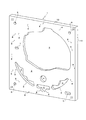
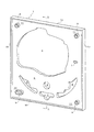
図1〜図3に示した長方形板状の遊技板1は、本発明に係る射出成形用金型に透明なポリカーボネイト樹脂、ABS樹脂、アクリロニトリル樹脂等の合成樹脂を射出することにより一体成形されたもので、該遊技板1の中央部に厚さ10mm程度で表面が平坦なるように遊技領域2が成形され、該遊技領域2に機種に応じた配置にて多数の障害釘が打ち込まれる。3は電子ディスプレイやセンター役物等の大型の遊技部品を取り付けるために該遊技領域に表裏貫通状に形成された大きな開口、4は該開口3の下部であって始動用可変入賞装置等の遊技部品を取り付けるために表裏貫通状に形成された開口、5はさらに該開口4の下部であって大入賞口装置等の遊技部品を取り付けるために表裏貫通状に形成された開口、6は該遊技板1の下部両側に普通入賞装置、装飾部材等の遊技部品を取り付けるために表裏貫通状に形成された開口、7は通過チャッカー等の遊技部品を取り付けるために遊技領域2に表裏貫通状に形成された小さな開口である。なお、8は遊技板1の表面にガイドレール(図示せず)を固定ピンにより固定するためにガイドレールの長手方向に沿って所定間隔で多数形成した固定ピン差込用の小孔、9は遊技板1の四隅角部にその組付、位置合わせ、配線通し等のために形成された貫通孔である。また、10は該遊技板1の外周縁に裏側へ額縁状に突出するように成形された外縁リブである。11は遊技領域2の外側(ガイドレールが装着されるラインの外側)の非遊技領域を示す。
The rectangular board-shaped
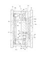
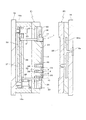
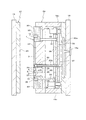
次にこの遊技板1を成形する射出成形用金型および成形方法の実施例を図4〜図7に従い説明する。同図において、20は固定盤18に固設された射出成形用金型の固定型、21は該固定型と相対するように可動盤19の前面に桁部材19aを介して固設された可動型で、図4に示した状態では固定型20に対し可動型21を進出させて型閉状態とすることにより、両型間にキャビティーが形成される。そして射出成形機の射出ノズル(図示しない)から合成樹脂が固定盤18に設けられたスプルーブッシュ18aを介して固定型20内に形成されたホットランナ20aを経て該キャビティーに射出されることにより、遊技板1が成形される。なお、固定型20には遊技板1の遊技領域2を含む前面全体を成形するため凹窪状の型面22が該キャビティーに面するように形成されている。
Next, an embodiment of an injection mold for molding the
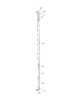
一方、可動型21には、図示したように、遊技領域2にある前記開口3〜5を形成するためのコア部23〜25が形成され、図4に示した型閉状態では該各コア部は先端面を固定型20の型面22に圧接させた状態としている。そしてこれらのコア部23〜25の外周に相当する可動型21前面の凹窪部26に遊技領域成形用型板30が進退動可能に設けられる。なお、図示していないが、可動型21にはコア部23〜25の他、前記開口6,7を形成するためのコア部、および前記小孔8、貫通孔9を形成するための突状部もそれぞれ形成される。31は遊技領域成形用型板30を進退動させるために該型板30の背後に縦に設けられた突出棒、32は該突出棒の基端部を当接させている突出プレート、33は該突出プレートに固設した油圧シリンダで、該油圧シリンダのピストンロッドが可動盤19の前面に止着され、該油圧シリンダを作動することにより、該突出プレート32を進退動させ、突出棒31を突出させる。該突出棒31と突出プレート32と油圧シリンダ33とにより先行離型手段が構成される。なお、突出棒31および油圧シリンダ33は図面ではそれぞれ1本であるが、これらは遊技領域成形用型板30を進退動させるために必要に応じて複数本設けられる。
On the other hand, as shown in the figure, the
また、35は遊技領域成形用型板30に対して独立して進退動可能なるように設けられた外周域成形用型板、36は該外周域成形用型板を進退動させるために該型板35の背後に縦に設けられた突出棒、37は該突出棒の基端部を当接させている突出プレート、38は該突出プレートに固設した油圧シリンダで、該油圧シリンダのピストンロッドが可動盤19の前面に止着され、該油圧シリンダを作動することにより、該突出プレート37を進退動させ、突出棒36を突出させる。該突出棒36と突出プレート37と油圧シリンダ38とにより後行離型手段が構成され、後述するように、該油圧シリンダ38は前記油圧シリンダ33が作動した後に作動するよう設定される。なお、突出棒36および油圧シリンダ38は図面ではそれぞれ1本であるが、これらについても外周域成形用型板35を進退動させるために必要に応じて複数本設けられる。39は該突出棒36の基端部を突出プレート37上に保持するために設けられた保持プレートである。
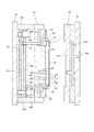
このように構成された射出成形用金型では、図4に示したようにキャビティーに射出された合成樹脂が冷却・固化することにより遊技板1が成形される。そして、図5に示したように可動盤19、可動型21を後退させることにより型開する。この型開時に図6に示したように先ず油圧シリンダ33を作動させることにより突出プレート32を介して突出棒31を突出させ遊技領域成形用型板30と外周域成形用型板35とを同時に一体的に突き出す。この作動によりコア部23〜25から遊技板1を離脱させる。なおこのとき遊技板1はその他のコア部および前記突状部からも離脱する。この離脱作動時に遊技領域成形用型板30と外周域成形用型板35とが該遊技板1の裏面全体を押圧することによりその押圧力が分散する。このため、遊技板1が肉厚で大きな開口3が存在することで離型抵抗が大きいにも拘わらず、遊技領域2の裏面を傷付けたり、押圧跡を残したりするおそれがない。
In the injection mold thus configured, the
その後、油圧シリンダ38を作動させ、図7に示したように、突出プレート37を介して突出棒36を突出させ、外周域成形用型板35をさらに突き出し、該外周域成形用型板35によって遊技板1の外縁リブ10の端面を押圧することにより該遊技板1を遊技領域成形用型板30から離脱させる。このように、遊技板1を遊技領域成形用型板30から離脱させる際も、外周域成形用型板35が遊技板1の外縁リブ10の端面を押圧することから、遊技領域2の裏面を傷付けたり、押圧跡を残したりすることがない。
Thereafter, the
なお、この実施形態では、油圧シリンダ33と油圧シリンダ38を設け、第1段階で油圧シリンダ33を作動させ、第2段階で油圧シリンダ38を作動させるようにしたが、可動盤19、可動型21が後退動する過程で、先ず突出プレート32が射出成形機に設けられた固定体(図示しない)に当たることで油圧シリンダ33を作動させるのと同様に突出棒31を突出させ遊技領域成形用型板30と外周域成形用型板35とが同時に一体的に突き出され、次いで突出プレート37が固定体(図示しない)に当たることで油圧シリンダ38を作動させるのと同様に突出棒36を突出させ外周域成形用型板35がさらに突き出されるように構成することもできる。この射出成形用金型は、可動型21内に独立して進退動する突出プレート32と突出プレート37とを設けたことにより、自由なタイミングで2段階にて遊技板を離型させることを可能にしている。
In this embodiment, the
このように本発明に係る遊技板1は射出成形により製造され、押出成形のように開口等を切削加工しないため、材料の歩留まりがよく、生産性もよい。そして本発明によっては、遊技板1の裏面に傷や押圧跡が付いて遊技領域の透明性、透光性が損なわれるようなおそれがなく、図柄変動表示装置や電飾等各種装飾部材をパチンコ遊技機等の遊技機における遊技板1の内側に配置することにより、遊技者が遊技板1内を鮮明に透視することができるとともに、電飾の光がよく通り、斬新な演出を行うことができる。なお、本発明によって成形される遊技板は、無色透明のものに限らず、有色透明のものや半透明、透光性のものにすることができる。
As described above, the
本発明によれば、遊技板の裏面に傷や押圧跡が全く付かないように成形することを可能にするが、透明性、透光性の遊技板であっても、例えば、非遊技領域11のように、透明性、透光性を必要とせず押圧跡があっても支障がないような部位を突出ピンによって補助的に押圧することで遊技板を離型させてもよい。例えば、図8に示したように、突出プレート37上に突出ピン40を設け、該突出ピン40を遊技領域成形用型板30に貫通させて遊技板の裏面に対向させ、油圧シリンダ38を作動させることにより外周域成形用型板35が突き出されるのと同時に該突出ピン40が突き出されるようにする。このように、突出ピン40を併用することによっても、面積の広い大型の遊技板を変形のおそれなく高精度に成形することができる。なお、図8について図7と同一符号は同一部分を示す。
According to the present invention, it is possible to mold the back of the game board so as not to be scratched or pressed at all. However, even if it is a transparent and translucent game board, for example, the
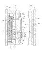
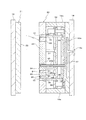
実施例1に示した射出成形用金型は、固定型20に遊技板1の遊技領域2を含む前面全体を成形するため型面22を形成し、可動型21にコア部23〜25、遊技領域成形用型板30および外周域成形用型板35を設けたが、本発明の実施例2として図9〜図12に示した射出成形用金型は、固定型20にコア部23〜25、遊技領域成形用型板30および外周域成形用型板35を設け、可動型21に型面22を形成したものである。即ち、この実施例では、可動型21に平面状の型面22を形成する一方、固定盤18の前面に桁部材19aを介して固定型20を固設し、該固定型20に開口3〜5を形成するためのコア部23〜25を形成するとともに、該固定型20前面の凹窪部26に遊技領域成形用型板30を進退動可能に設け、該型板30の背後に突出棒31を設け、該突出棒31を突出させるために該突出棒31と突出プレート32と油圧シリンダ33とにより先行離型手段を構成し、さらに、該遊技領域成形用型板30に対して独立して進退動可能なるように外周域成形用型板35を設け、該型板35の背後に突出棒36を設け、該突出棒36を突出させるために該突出棒36と突出プレート37と油圧シリンダ38とにより後行離型手段を構成し、該油圧シリンダ38を油圧シリンダ33が作動した後に作動するよう設定したものである。なお、20bはキャビティーに樹脂を射出するためホットランナ20aと連通するように固定盤18の前面に突出するように設けられた射出ノズルである。その他、この実施例2における実施例1と同一符号は同一部分または相当部分を示す。
In the injection mold shown in the first embodiment, a
このように構成した射出成形用金型では、図10に示したように可動盤19、可動型21を後退させ型開した状態にて、図11に示したように、先ず油圧シリンダ33を作動させることにより、突出プレート32を介して突出棒31を突出させ遊技領域成形用型板30と外周域成形用型板35とを同時に一体的に突き出し、コア部23〜25から遊技板1を離脱させる。このとき遊技領域成形用型板30と外周域成形用型板35とが該遊技板1の裏面全体を押圧することにより押圧力が分散され、遊技領域2の裏面を傷付けたり、押圧跡を残すおそれがない。その後、油圧シリンダ38を作動させ、図12に示したように、外周域成形用型板35のみをさらに突き出し、該外周域成形用型板35によって遊技板1の外縁リブ10の端面を押圧することにより該遊技板1を遊技領域成形用型板30から離脱させる。
In the injection molding die constructed as described above, the
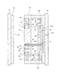
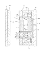
また、図13〜図16に示した実施例3は、実施例2と同様に、固定型20にコア部23〜25、遊技領域成形用型板30および外周域成形用型板35を設け、可動型21に型面22を形成したものであるが、油圧シリンダ33と突出プレート32と突出棒31とからなる先行離型手段を作動させることにより図15に示したようにコア部23〜25が後退動し、その後に油圧シリンダ38と突出プレート37と突出棒36とからなる後行離型手段を作動させることにより図16に示したように外周域成形用型板35が突出するように構成したものである。このような型構造とした場合にも裏面に傷や押圧跡がない遊技板1を成形することができる。この実施例3についても実施例1、2と同一符号は同一部分または相当部分を示す。
なお、この実施例3に場合も実施例1と同様に、油圧シリンダ38を作動させることにより外周域成形用型板35が突出されるのと同時に突出ピンが突出されるようにしてもよい。この場合に、突出ピンを非遊技領域11に配置することにより、遊技領域2に押圧跡を残さないようにすることができる。
Further, in the third embodiment shown in FIGS. 13 to 16, similarly to the second embodiment, the fixed
In the case of the third embodiment, as in the first embodiment, the projecting pin may be projected at the same time that the outer peripheral
なお、実施例2および実施例3では、図17に拡大図を示したように、遊技板1の外縁リブ10の外周面がテーパ面状に形成され、該テーパ面に外周域成形用型板35を係合させることで、遊技板1を押し出し得るようにしている。このようにテーパ面状に形成することにより、遊技板1が外周域成形用型板35から離脱し易くなる。
In Example 2 and Example 3, as shown in an enlarged view in FIG. 17, the outer peripheral surface of the
以上、実施例について説明したように本発明は、遊技板の前面全体を成形するための型面22が固定型20または可動型21のいずれか一方に形成され、コア部23〜25、遊技領域成形用型板30および外周域成形用型板35が該型面22と相対する固定型20または可動型21に設けられる。即ち、固定型20または可動型21を一方型とし、該一方型と相対する固定型または可動型を他方型とすると、一方型に型面22を形成し、他方型にコア部23〜25、遊技領域成形用型板30および外周域成形用型板35を設ければよい。そして、先行離型手段を作動させて遊技領域成形用型板30と外周域成形用型板35とを同時に一体的にコア部23〜25に対して相対的に突き出すことにより該コア部から遊技板1を離脱させた後、後行離型手段を作動させて外周域成形用型板35を遊技領域成形用型板30からさらに相対的に突き出して該遊技板1を遊技領域成形用型板30から離脱させることにより、遊技領域に傷や押圧跡のない合成樹脂製の遊技板1を射出成形により効率よく製造することを可能にする。
As described above, according to the present invention, in the present invention, the
1 遊技板
2 遊技領域
3〜7 開口
10 外縁リブ
11 非遊技領域
20 固定型
21 可動型
22 型面
23〜25 コア部
26 凹窪部
30 遊技領域成形用型板
31 突出棒
32 突出プレート
33 油圧シリンダ
35 外周域成形用型板
36 突出棒
37 突出プレート
38 油圧シリンダ
DESCRIPTION OF
Claims (2)
Priority Applications (1)
| Application Number | Priority Date | Filing Date | Title |
|---|---|---|---|
| JP2012013480A JP6038457B2 (en) | 2012-01-25 | 2012-01-25 | Game board molding method |
Applications Claiming Priority (1)
| Application Number | Priority Date | Filing Date | Title |
|---|---|---|---|
| JP2012013480A JP6038457B2 (en) | 2012-01-25 | 2012-01-25 | Game board molding method |
Publications (2)
| Publication Number | Publication Date |
|---|---|
| JP2013150724A JP2013150724A (en) | 2013-08-08 |
| JP6038457B2 true JP6038457B2 (en) | 2016-12-07 |
Family
ID=49047646
Family Applications (1)
| Application Number | Title | Priority Date | Filing Date |
|---|---|---|---|
| JP2012013480A Active JP6038457B2 (en) | 2012-01-25 | 2012-01-25 | Game board molding method |
Country Status (1)
| Country | Link |
|---|---|
| JP (1) | JP6038457B2 (en) |
Families Citing this family (8)
| Publication number | Priority date | Publication date | Assignee | Title |
|---|---|---|---|---|
| JP5925601B2 (en) * | 2012-05-30 | 2016-05-25 | 株式会社足立ライト工業所 | Injection molding method and injection mold |
| JP7691712B2 (en) * | 2022-11-28 | 2025-06-12 | 株式会社大一商会 | Gaming Machines |
| JP7691711B2 (en) * | 2022-11-28 | 2025-06-12 | 株式会社大一商会 | Gaming Machines |
| JP7691709B2 (en) * | 2022-11-28 | 2025-06-12 | 株式会社大一商会 | Gaming Machines |
| JP7691714B2 (en) * | 2022-11-28 | 2025-06-12 | 株式会社大一商会 | Gaming Machines |
| JP7691713B2 (en) * | 2022-11-28 | 2025-06-12 | 株式会社大一商会 | Gaming Machines |
| JP7691708B2 (en) * | 2022-11-28 | 2025-06-12 | 株式会社大一商会 | Gaming Machines |
| JP7691710B2 (en) * | 2022-11-28 | 2025-06-12 | 株式会社大一商会 | Gaming Machines |
Family Cites Families (3)
| Publication number | Priority date | Publication date | Assignee | Title |
|---|---|---|---|---|
| JP2796204B2 (en) * | 1991-05-31 | 1998-09-10 | アルゼ株式会社 | Gaming board for ball game machine |
| JP4110300B2 (en) * | 1997-05-23 | 2008-07-02 | タイヨーエレック株式会社 | Method for manufacturing game board of bullet ball gaming machine |
| JP2005276770A (en) * | 2004-03-26 | 2005-10-06 | Nichias Corp | Separator for fuel cell, manufacturing method and manufacturing apparatus thereof |
-
2012
- 2012-01-25 JP JP2012013480A patent/JP6038457B2/en active Active
Also Published As
| Publication number | Publication date |
|---|---|
| JP2013150724A (en) | 2013-08-08 |
Similar Documents
| Publication | Publication Date | Title |
|---|---|---|
| JP6038457B2 (en) | Game board molding method | |
| CN205588574U (en) | Injection mold of two - color plastic goods of equal difference of front and back mould | |
| JP5925601B2 (en) | Injection molding method and injection mold | |
| JP5959859B2 (en) | Game board molding method | |
| CN103737805B (en) | The precision die of notebook computer base bonnet | |
| CN101767410B (en) | Double-color mold with sequential slider drive mechanism | |
| CN104802370A (en) | Mold of front mold ejection and demolding structure | |
| KR200421064Y1 (en) | Slope Undercut Treatment Structure | |
| JP5875411B2 (en) | Injection compression molding method and injection compression mold | |
| KR20090004630U (en) | Slide core for vertical and horizontal undercut ejection | |
| CN216579042U (en) | Exchange mold insert mechanism injection mold fast | |
| CN210308891U (en) | Back-off core-pulling injection mold | |
| JP6490906B2 (en) | Game board mold and game board | |
| JP2002347085A (en) | Injection-molding mold | |
| KR20080004359U (en) | Mold assembly | |
| JP6490905B2 (en) | Game board mold and game board | |
| CN202097869U (en) | Mold with controlled deformation structure | |
| KR200347911Y1 (en) | A metal mold that molding shape is changed | |
| KR0136498Y1 (en) | Gate automatic cutting device of mold | |
| KR200280828Y1 (en) | A metallic mold having slider with injection gateway function | |
| JP7731125B2 (en) | Injection mold | |
| CN223147628U (en) | Injection mold | |
| CN119427679B (en) | Injection mold fixed mold side spring block demoulding mechanism | |
| KR100636804B1 (en) | Method of manufacturing a release member assembly for a mobile phone | |
| CN216100195U (en) | Inclined pulling structure of precision mold |
Legal Events
| Date | Code | Title | Description |
|---|---|---|---|
| A621 | Written request for application examination |
Free format text: JAPANESE INTERMEDIATE CODE: A621 Effective date: 20150114 |
|
| A977 | Report on retrieval |
Free format text: JAPANESE INTERMEDIATE CODE: A971007 Effective date: 20151209 |
|
| A131 | Notification of reasons for refusal |
Free format text: JAPANESE INTERMEDIATE CODE: A131 Effective date: 20151217 |
|
| A521 | Request for written amendment filed |
Free format text: JAPANESE INTERMEDIATE CODE: A523 Effective date: 20160121 |
|
| A131 | Notification of reasons for refusal |
Free format text: JAPANESE INTERMEDIATE CODE: A131 Effective date: 20160531 |
|
| A521 | Request for written amendment filed |
Free format text: JAPANESE INTERMEDIATE CODE: A523 Effective date: 20160629 |
|
| TRDD | Decision of grant or rejection written | ||
| A01 | Written decision to grant a patent or to grant a registration (utility model) |
Free format text: JAPANESE INTERMEDIATE CODE: A01 Effective date: 20161011 |
|
| A61 | First payment of annual fees (during grant procedure) |
Free format text: JAPANESE INTERMEDIATE CODE: A61 Effective date: 20161102 |
|
| R150 | Certificate of patent or registration of utility model |
Ref document number: 6038457 Country of ref document: JP Free format text: JAPANESE INTERMEDIATE CODE: R150 |
|
| R250 | Receipt of annual fees |
Free format text: JAPANESE INTERMEDIATE CODE: R250 |
|
| R250 | Receipt of annual fees |
Free format text: JAPANESE INTERMEDIATE CODE: R250 |
|
| R250 | Receipt of annual fees |
Free format text: JAPANESE INTERMEDIATE CODE: R250 |