JP6038112B2 - Method for classification of tooth surfaces - Google Patents
Method for classification of tooth surfaces Download PDFInfo
- Publication number
- JP6038112B2 JP6038112B2 JP2014501167A JP2014501167A JP6038112B2 JP 6038112 B2 JP6038112 B2 JP 6038112B2 JP 2014501167 A JP2014501167 A JP 2014501167A JP 2014501167 A JP2014501167 A JP 2014501167A JP 6038112 B2 JP6038112 B2 JP 6038112B2
- Authority
- JP
- Japan
- Prior art keywords
- boundary
- tooth
- ratio
- image
- grayscale value
- Prior art date
- Legal status (The legal status is an assumption and is not a legal conclusion. Google has not performed a legal analysis and makes no representation as to the accuracy of the status listed.)
- Expired - Fee Related
Links
Images


Classifications
-
- G—PHYSICS
- G06—COMPUTING OR CALCULATING; COUNTING
- G06T—IMAGE DATA PROCESSING OR GENERATION, IN GENERAL
- G06T7/00—Image analysis
- G06T7/0002—Inspection of images, e.g. flaw detection
- G06T7/0012—Biomedical image inspection
-
- G—PHYSICS
- G06—COMPUTING OR CALCULATING; COUNTING
- G06T—IMAGE DATA PROCESSING OR GENERATION, IN GENERAL
- G06T9/00—Image coding
- G06T9/20—Contour coding, e.g. using detection of edges
-
- A—HUMAN NECESSITIES
- A61—MEDICAL OR VETERINARY SCIENCE; HYGIENE
- A61B—DIAGNOSIS; SURGERY; IDENTIFICATION
- A61B5/00—Measuring for diagnostic purposes; Identification of persons
- A61B5/0059—Measuring for diagnostic purposes; Identification of persons using light, e.g. diagnosis by transillumination, diascopy, fluorescence
- A61B5/0071—Measuring for diagnostic purposes; Identification of persons using light, e.g. diagnosis by transillumination, diascopy, fluorescence by measuring fluorescence emission
-
- A—HUMAN NECESSITIES
- A61—MEDICAL OR VETERINARY SCIENCE; HYGIENE
- A61B—DIAGNOSIS; SURGERY; IDENTIFICATION
- A61B5/00—Measuring for diagnostic purposes; Identification of persons
- A61B5/0059—Measuring for diagnostic purposes; Identification of persons using light, e.g. diagnosis by transillumination, diascopy, fluorescence
- A61B5/0082—Measuring for diagnostic purposes; Identification of persons using light, e.g. diagnosis by transillumination, diascopy, fluorescence adapted for particular medical purposes
- A61B5/0088—Measuring for diagnostic purposes; Identification of persons using light, e.g. diagnosis by transillumination, diascopy, fluorescence adapted for particular medical purposes for oral or dental tissue
-
- A—HUMAN NECESSITIES
- A61—MEDICAL OR VETERINARY SCIENCE; HYGIENE
- A61B—DIAGNOSIS; SURGERY; IDENTIFICATION
- A61B5/00—Measuring for diagnostic purposes; Identification of persons
- A61B5/45—For evaluating or diagnosing the musculoskeletal system or teeth
- A61B5/4538—Evaluating a particular part of the muscoloskeletal system or a particular medical condition
- A61B5/4542—Evaluating the mouth, e.g. the jaw
- A61B5/4547—Evaluating teeth
-
- A—HUMAN NECESSITIES
- A61—MEDICAL OR VETERINARY SCIENCE; HYGIENE
- A61B—DIAGNOSIS; SURGERY; IDENTIFICATION
- A61B6/00—Apparatus or devices for radiation diagnosis; Apparatus or devices for radiation diagnosis combined with radiation therapy equipment
- A61B6/50—Apparatus or devices for radiation diagnosis; Apparatus or devices for radiation diagnosis combined with radiation therapy equipment specially adapted for specific body parts; specially adapted for specific clinical applications
- A61B6/51—Apparatus or devices for radiation diagnosis; Apparatus or devices for radiation diagnosis combined with radiation therapy equipment specially adapted for specific body parts; specially adapted for specific clinical applications for dentistry
-
- A—HUMAN NECESSITIES
- A61—MEDICAL OR VETERINARY SCIENCE; HYGIENE
- A61B—DIAGNOSIS; SURGERY; IDENTIFICATION
- A61B6/00—Apparatus or devices for radiation diagnosis; Apparatus or devices for radiation diagnosis combined with radiation therapy equipment
- A61B6/52—Devices using data or image processing specially adapted for radiation diagnosis
- A61B6/5211—Devices using data or image processing specially adapted for radiation diagnosis involving processing of medical diagnostic data
- A61B6/5217—Devices using data or image processing specially adapted for radiation diagnosis involving processing of medical diagnostic data extracting a diagnostic or physiological parameter from medical diagnostic data
-
- A—HUMAN NECESSITIES
- A61—MEDICAL OR VETERINARY SCIENCE; HYGIENE
- A61C—DENTISTRY; APPARATUS OR METHODS FOR ORAL OR DENTAL HYGIENE
- A61C9/00—Impression cups, i.e. impression trays; Impression methods
- A61C9/004—Means or methods for taking digitized impressions
- A61C9/0046—Data acquisition means or methods
-
- G—PHYSICS
- G01—MEASURING; TESTING
- G01J—MEASUREMENT OF INTENSITY, VELOCITY, SPECTRAL CONTENT, POLARISATION, PHASE OR PULSE CHARACTERISTICS OF INFRARED, VISIBLE OR ULTRAVIOLET LIGHT; COLORIMETRY; RADIATION PYROMETRY
- G01J3/00—Spectrometry; Spectrophotometry; Monochromators; Measuring colours
- G01J3/46—Measurement of colour; Colour measuring devices, e.g. colorimeters
- G01J3/50—Measurement of colour; Colour measuring devices, e.g. colorimeters using electric radiation detectors
- G01J3/508—Measurement of colour; Colour measuring devices, e.g. colorimeters using electric radiation detectors measuring the colour of teeth
-
- G—PHYSICS
- G16—INFORMATION AND COMMUNICATION TECHNOLOGY [ICT] SPECIALLY ADAPTED FOR SPECIFIC APPLICATION FIELDS
- G16H—HEALTHCARE INFORMATICS, i.e. INFORMATION AND COMMUNICATION TECHNOLOGY [ICT] SPECIALLY ADAPTED FOR THE HANDLING OR PROCESSING OF MEDICAL OR HEALTHCARE DATA
- G16H50/00—ICT specially adapted for medical diagnosis, medical simulation or medical data mining; ICT specially adapted for detecting, monitoring or modelling epidemics or pandemics
- G16H50/30—ICT specially adapted for medical diagnosis, medical simulation or medical data mining; ICT specially adapted for detecting, monitoring or modelling epidemics or pandemics for calculating health indices; for individual health risk assessment
-
- A—HUMAN NECESSITIES
- A61—MEDICAL OR VETERINARY SCIENCE; HYGIENE
- A61B—DIAGNOSIS; SURGERY; IDENTIFICATION
- A61B5/00—Measuring for diagnostic purposes; Identification of persons
- A61B5/72—Signal processing specially adapted for physiological signals or for diagnostic purposes
- A61B5/7235—Details of waveform analysis
- A61B5/7264—Classification of physiological signals or data, e.g. using neural networks, statistical classifiers, expert systems or fuzzy systems
- A61B5/7267—Classification of physiological signals or data, e.g. using neural networks, statistical classifiers, expert systems or fuzzy systems involving training the classification device
-
- G—PHYSICS
- G06—COMPUTING OR CALCULATING; COUNTING
- G06T—IMAGE DATA PROCESSING OR GENERATION, IN GENERAL
- G06T2207/00—Indexing scheme for image analysis or image enhancement
- G06T2207/10—Image acquisition modality
- G06T2207/10064—Fluorescence image
-
- G—PHYSICS
- G06—COMPUTING OR CALCULATING; COUNTING
- G06T—IMAGE DATA PROCESSING OR GENERATION, IN GENERAL
- G06T2207/00—Indexing scheme for image analysis or image enhancement
- G06T2207/20—Special algorithmic details
- G06T2207/20081—Training; Learning
-
- G—PHYSICS
- G06—COMPUTING OR CALCULATING; COUNTING
- G06T—IMAGE DATA PROCESSING OR GENERATION, IN GENERAL
- G06T2207/00—Indexing scheme for image analysis or image enhancement
- G06T2207/30—Subject of image; Context of image processing
- G06T2207/30004—Biomedical image processing
- G06T2207/30036—Dental; Teeth
-
- G—PHYSICS
- G06—COMPUTING OR CALCULATING; COUNTING
- G06V—IMAGE OR VIDEO RECOGNITION OR UNDERSTANDING
- G06V2201/00—Indexing scheme relating to image or video recognition or understanding
- G06V2201/03—Recognition of patterns in medical or anatomical images
Landscapes
- Health & Medical Sciences (AREA)
- Life Sciences & Earth Sciences (AREA)
- Engineering & Computer Science (AREA)
- Medical Informatics (AREA)
- Physics & Mathematics (AREA)
- General Health & Medical Sciences (AREA)
- Public Health (AREA)
- Animal Behavior & Ethology (AREA)
- Veterinary Medicine (AREA)
- Biomedical Technology (AREA)
- Pathology (AREA)
- Heart & Thoracic Surgery (AREA)
- Molecular Biology (AREA)
- Surgery (AREA)
- Biophysics (AREA)
- Oral & Maxillofacial Surgery (AREA)
- Dentistry (AREA)
- Radiology & Medical Imaging (AREA)
- Nuclear Medicine, Radiotherapy & Molecular Imaging (AREA)
- General Physics & Mathematics (AREA)
- Optics & Photonics (AREA)
- High Energy & Nuclear Physics (AREA)
- Computer Vision & Pattern Recognition (AREA)
- Spectroscopy & Molecular Physics (AREA)
- Theoretical Computer Science (AREA)
- Epidemiology (AREA)
- Quality & Reliability (AREA)
- Physiology (AREA)
- Physical Education & Sports Medicine (AREA)
- Orthopedic Medicine & Surgery (AREA)
- Rheumatology (AREA)
- Audiology, Speech & Language Pathology (AREA)
- Databases & Information Systems (AREA)
- Primary Health Care (AREA)
- Data Mining & Analysis (AREA)
- Multimedia (AREA)
- Dental Tools And Instruments Or Auxiliary Dental Instruments (AREA)
- Image Processing (AREA)
- Image Analysis (AREA)
- Endoscopes (AREA)
Description
本発明は、一般に、口腔内および歯科画像処理に関する。より具体的には、その後に続く処理のための歯の表面の分類のための方法に関する。 The present invention relates generally to intraoral and dental image processing. More specifically, it relates to a method for classification of tooth surfaces for subsequent processing.
検出、治療、予防手法の改善にもかかわらず、虫歯は、すべての年齢群の人々を冒す広く流行している疾患であり続けている。適切かつ直ちに治療が行われないと、齲蝕は、永久的な歯の損傷、歯の喪失さえにも成る可能性がある。 Despite improved detection, treatment, and prevention techniques, dental caries continue to be a prevalent disease affecting people of all ages. If not properly and immediately treated, caries can result in permanent tooth damage, even tooth loss.
齲蝕検出の従来の方法は、放射線(X線)画像処理によってしばしば補助される、視覚による検査および尖った歯科用探針器での触診を含む。これらの方法を利用した検出は、幾分主観的である可能性があって、開業医の経験、感染部位の場所、感染の程度、観察条件、X線装置および処理の精度、ならびに他の要素を含む多くの要素のため精度に変化がある。従来の検出手法に関連して、X線照射への暴露の他、脆弱化した歯を害し、触診方法により感染を拡大するリスクもある。齲蝕が視覚、触診検査で明らかになる時までには、疾病は、一般に進行したステージにあり、充填剤が必要で、時宜を得て治療されなければ歯の喪失に至る可能性がある。 Conventional methods of caries detection include visual inspection and palpation with a pointed dental probe, often aided by radiation (X-ray) imaging. Detection using these methods can be somewhat subjective, and includes practitioner experience, location of infection site, degree of infection, observation conditions, accuracy of x-ray equipment and processing, and other factors. There are variations in accuracy due to many factors including. In addition to exposure to X-ray irradiation, there is a risk of harming weakened teeth and spreading infection by palpation methods in connection with conventional detection techniques. By the time the caries becomes apparent by visual and palpation, the disease is generally at an advanced stage, requires fillers and can lead to tooth loss if not treated in a timely manner.
改善された齲蝕検出方法の必要に応えて、X線を採用しない改善された画像処理手法に大いに関心があった。商用化された1つの方法は、歯が高輝度の青色光を照射されたときに起こる蛍光発光を採用している。この手法は、量子光誘起蛍光発光(QLF)と称され、いくつかの波長による励起下で健全で健康な歯のエナメル質が齲蝕感染によって損傷された非石灰化エナメル質よりもより高輝度の蛍光発光を発生させる原理に基づいて動作する。石灰化分の喪失と青色光励起の蛍光発光の喪失との強い相関関係は、したがって歯の齲蝕領域の特定および評価に利用される。スペクトルのある領域で、齲蝕領域のバクテリアおよびバクテリアの副産物が健康な領域よりもより顕著に吸収し、蛍光発光する別の関係が、赤色光励起で発見された。 In response to the need for improved caries detection methods, there has been much interest in improved image processing techniques that do not employ X-rays. One method that has been commercialized employs fluorescence emission that occurs when teeth are illuminated with high intensity blue light. This technique is called Quantum Light Induced Fluorescence (QLF), which is brighter than non-calcified enamel in which healthy and healthy tooth enamel is damaged by caries infection under excitation by several wavelengths. It operates on the principle of generating fluorescence. The strong correlation between the loss of calcification and the loss of fluorescence emission of blue light excitation is therefore exploited in the identification and evaluation of dental caries areas. In a region of the spectrum, another relationship was found with red light excitation where bacteria and bacteria by-products in the caries region absorb more significantly and fluoresce than in the healthy region.
蛍光発光手法において、得られる画像コントラストは、疾患の重症度に対応すると認識されている。これらの手法を利用した齲蝕の正確な特定は、齲蝕と健全な歯の構造との間の蛍光発光の違いが早期ステージの齲蝕では非常に小さいので、初期または早期齲蝕を超えて疾患がより進行したステージであることをしばしば必要とする。このような場合では、蛍光発光手法を利用した検出精度は、従来の方法に対して、際立った改善を示さないことがある。この理由で、蛍光発光効果の利用は、初期齲蝕の正確な診断を妨げる実用限界を有するように見える。その結果、齲蝕疾患は、より重大、例えば充填物を必要とするようになるまで、検出されずにあり続けることがある。 In fluorescent emission techniques, it is recognized that the resulting image contrast corresponds to the severity of the disease. The precise identification of caries using these methods is because the difference in fluorescence emission between caries and healthy tooth structure is very small in early stage caries, so the disease progresses beyond initial or early caries. Often need to be on stage. In such a case, the detection accuracy using the fluorescence emission method may not show a marked improvement over the conventional method. For this reason, the use of the fluorescence effect appears to have practical limits that prevent accurate diagnosis of initial caries. As a result, caries disease may remain undetected until it becomes more serious, for example, it requires a filling.
極早期ステージにおける齲蝕の検出は、予防歯科にとって特別な関心がある。すでに説明したように、従来の手法では、疾患が回復させることのできるステージで齲蝕を検出するのに、概して失敗する。経験に基づくと、初期齲蝕は歯のエナメル質内部まで実質的には侵入していない病変である。歯の象牙質部分を脅かす前にそのような齲蝕病変が特定されるときに、早期損傷を回復し、充填物の必要を防ぐ再石灰化がしばしば達成されることができる。より進行した齲蝕は、しかしながら、治療することが増大的により困難になり、非常に多くの場合、ある種類の充填またはその他の種類の治療介入を必要とする。 The detection of caries in the very early stage is of special interest for preventive dentistry. As already explained, conventional approaches generally fail to detect caries at a stage where the disease can be recovered. Based on experience, initial caries is a lesion that has not penetrated substantially into the enamel of the tooth. When such carious lesions are identified before threatening the dentin portion of the tooth, remineralization can often be achieved to restore early damage and prevent the need for filling. More advanced caries, however, becomes increasingly more difficult to treat and very often requires some type of filling or other type of therapeutic intervention.
齲蝕を未然に防ぐための非侵襲的歯科手法の機会を活用するために、発症時に齲蝕が検出されるのが望ましい。多くの場合において、検出のこのレベルは、QLF等、既存の蛍光発光画像処理手法を利用して達成するのは、困難であることが発見された。その結果、早期齲蝕は、検出されずにあり続ける可能性があり、したがって、陽性の検出が得られたときには、低コストの予防的措置を利用した回復の機会が失われている可能性がある。 In order to take advantage of the opportunity of non-invasive dental procedures to prevent caries, it is desirable that caries be detected at the time of onset. In many cases, this level of detection has been found difficult to achieve using existing fluorescence imaging techniques such as QLF. As a result, early caries can continue to be undetected and, therefore, if a positive detection is obtained, chances of recovery using low-cost precautionary measures may be lost .
同一出願人による米国特許出願第2008/0056551号において、歯の反射率および蛍光発光画像両者を採用する方法および装置が齲蝕を検出するために利用される。齲蝕を検出するための改善された歯科画像処理手法を提供するために初期齲蝕のために蛍光発光効果と組み合わせて、観測される後方散乱または反射率を採用する。この手法は、反射率増進を伴う蛍光発光画像処理(FIRE)と称され、以前のアプローチよりも画像のコントラストを促進し、予防措置が効果を起こし易いステージでの初期齲蝕を検出する。有利なことに、FIRE検出は、蛍光発光のみを測定する既存の蛍光発光アプローチを利用するものに示されるより、齲蝕感染のより早いステージで正確である可能性がある。本出願は、FIRE画像を生成するための、ダウンシフト方法を説明する。 In commonly assigned US Patent Application No. 2008/0056551, a method and apparatus that employs both tooth reflectivity and fluorescence emission images is utilized to detect caries. Adopt the observed backscatter or reflectivity in combination with the fluorescent emission effect for the initial caries to provide an improved dental imaging technique for detecting caries. This technique, referred to as Fluorescence Emission Image Processing (FIRE) with enhanced reflectance, promotes image contrast over previous approaches and detects initial caries at stages where precautionary measures are likely to be effective. Advantageously, FIRE detection may be more accurate at an earlier stage of caries infection than shown using those that utilize existing fluorescence approaches that measure fluorescence only. This application describes a downshift method for generating a FIRE image.
同一出願人による同時係属の「METHOD FOR DETECTION OF CARIES」と題する第PCT/CN2009/000078号は、照射変化に対する低減された感度を伴うFIRE画像の生成のための形態的方法を説明する。 No. PCT / CN2009 / 000078 entitled “METHOD FOR DETECTION OF CARIES” by the same applicant describes a morphological method for generating FIRE images with reduced sensitivity to illumination changes.
歯の表面はそれ自体複雑である。歯の頬側および舌側表面は、特徴的に平滑であって、歯の片側から反対側へ漸次変化する輪郭を伴う。一方、咬合面は典型的に穴があり、歯の表面に渡って、著しい数のスロープおよび輪郭の推移がある。これら表面の特徴の相違点の結果、同じ種類の画像処理および分析手法は、両者の種類の歯の表面で同じようには、しばしば効果がない。頬側または舌側表面に沿った齲蝕領域の特徴的外観は、咬合面の齲蝕とは著しく異なる可能性がある。これら非類似の種類の表面は、齲蝕領域と鏡面反射のコントラストに関して、例えば異なって反応する可能性がある。低石灰化および他の効果は、疑わしい齲蝕領域を検出するように設計された画像処理アルゴリズムを混乱させる可能性がある。 The tooth surface is itself complex. The buccal and lingual surfaces of the teeth are characteristically smooth, with contours that gradually change from one side of the tooth to the other. On the other hand, the occlusal surface is typically perforated and there is a significant number of slopes and contour transitions across the tooth surface. As a result of these surface feature differences, the same types of image processing and analysis techniques are often not as effective as both types of tooth surfaces. The characteristic appearance of the carious region along the buccal or lingual surface can be significantly different from the carious surface caries. These dissimilar types of surfaces may react differently, for example, with respect to the caries area and the specular contrast. Hypocalcification and other effects can confuse image processing algorithms designed to detect suspicious carious areas.
齲蝕検出に加えて、歯の表面の特徴付けは、例えば、歯の色合いおよび外見に関連する処理を含む、他の種類の口腔内および歯科画像処理、ならびに口腔内画像の全般的な分類に有用である可能性がある。 In addition to caries detection, tooth surface characterization is useful for other types of intraoral and dental image processing, including, for example, processing related to tooth tint and appearance, and general classification of intraoral images There is a possibility.
したがって、他の処理はもちろん、齲蝕検出手法の適用を試みる前に歯の表面の種類を分類することは、有益であることが理解され得る。画像分析におけるこの追加のステップは、齲蝕検出精度を改善するのに寄与し、偽陽性の数を削減する可能性がある。 It can therefore be seen that it is beneficial to classify the tooth surface type before attempting to apply the caries detection technique as well as other processes. This additional step in image analysis contributes to improved caries detection accuracy and may reduce the number of false positives.
本発明の目的は、虫歯検出のための画像処理手法を促進することにある。本発明の実施形態は、歯の表面の性質に依存して、適切な画像処理方法が利用されることができるように歯の表面をより正確に分類する必要に対処するものである。本発明の方法の優位性は、歯の表面が平滑面または咬合面であることを、操作者の介入なしに、自動的に決定可能なことであり、したがって、齲蝕検出アルゴリズムがその次の適用されるときに、偽陽性の数を削減する。 An object of the present invention is to promote an image processing technique for caries detection. Embodiments of the present invention address the need to more accurately classify tooth surfaces so that appropriate image processing methods can be utilized, depending on the nature of the tooth surface. The advantage of the method of the present invention is that it can automatically determine that the tooth surface is a smooth or occlusal surface, without operator intervention, so that the caries detection algorithm can be applied in the next application. When it comes to reducing the number of false positives.
したがって、1つ以上の、以下の優位性を伴う歯の表面の分類方法が説明される。(1)歯の表面は、自動的に分類され得る、(2)結果はかなり堅牢であって、照射の変動には感応性がない、(3)本方法は、大規模の計算複雑性を利用せず、リアルタイムで実行され得る、(4)本方法は、静止画像または動画にて自動ハイライトを伴って齲蝕検出に利用される。本方法は、異なる種類の口腔内カメラ画像システムの多くで直ちに使用できる。本方法を応用することは、患者の歯の疾患を適切に評価するのに要される時間量を削減するのに、役立ち得る。 Accordingly, a method for classifying tooth surfaces with one or more of the following advantages is described. (1) The tooth surface can be automatically classified, (2) the results are fairly robust and insensitive to variations in irradiation, (3) the method has a large computational complexity (4) This method is used for caries detection with automatic highlighting in still images or moving images. The method can be used immediately with many different types of intraoral camera imaging systems. Applying this method can help reduce the amount of time required to properly assess a patient's dental disease.
これらの目的は、例証的な例としてのみ与えられ、かかる目的は、本発明の1つ以上の実施形態の例示であり得る。開示される発明によって本質的に達成される他の望ましい目的および利点が、当業者に想到されるか、または明らかとなり得る。本発明は、添付の特許請求の範囲によって規定される。 These objects are given as illustrative examples only, and such objects may be illustrative of one or more embodiments of the present invention. Other desirable objectives and advantages inherently achieved by the disclosed invention will occur or become apparent to those skilled in the art. The invention is defined by the appended claims.
本発明の一態様によれば、口腔内画像処理のための方法が提供され、該方法は、コンピュータシステム上で少なくとも部分的に実行され、1つ以上の歯のデジタル画像を得るステップと、1つ以上の歯の第1の境界および第2の境界を検出するステップと、第1の境界および第2の境界のそれぞれにおいて、境界の片側の歯領域の平均グレースケール値と、境界の反対側のバックグラウンド領域の平均グレースケール値との境界比を計算し、計算された境界比をメモリに記憶するステップと、第1の境界の近傍の歯領域の平均グレースケール値と、第2の境界の近傍の歯領域の平均グレースケール値との第3の比を計算し、第3の比をメモリに記憶するステップと、少なくとも計算された境界比および第3の比を含むベクトルを形成し、記憶するステップと、記憶されたベクトルに従って、歯の表面を平滑面または咬合面のいずれかに分類するステップと、歯の表面の分類に従って、デジタル画像を処理するステップと、処理結果を報告するステップと、を含む、方法である。 According to one aspect of the present invention, a method for intraoral image processing is provided, the method being performed at least partially on a computer system to obtain a digital image of one or more teeth; Detecting a first boundary and a second boundary of one or more teeth; an average grayscale value of a tooth region on one side of the boundary and an opposite side of the boundary in each of the first boundary and the second boundary; Calculating a boundary ratio with the average grayscale value of the background area of the first area, storing the calculated boundary ratio in a memory, an average grayscale value of the tooth area in the vicinity of the first boundary, and a second boundary Calculating a third ratio with an average gray scale value of the tooth region in the vicinity of the first and storing the third ratio in a memory, and forming a vector including at least the calculated boundary ratio and the third ratio; Memory Classifying the tooth surface as either a smooth surface or an occlusal surface according to the stored vector, processing the digital image according to the classification of the tooth surface, and reporting the processing results. , Including.
本発明の前述のおよび他の目的、特徴、および利点は、添付の図面において例証される、本発明の実施形態の次のより特定の説明から明らかとなるであろう。図面の要素は、相互に対して必ずしも一定の縮尺ではない。 The foregoing and other objects, features and advantages of the present invention will become apparent from the following more particular description of embodiments of the invention, as illustrated in the accompanying drawings. The elements of the drawings are not necessarily to scale relative to each other.
以下は、本発明の好ましい実施形態の詳細な説明であり、図面が参照され、その中で同一の参照番号は複数の図面のそれぞれにおいて同じ構造の要素を特定する。 The following is a detailed description of the preferred embodiments of the invention, reference being made to the drawings in which the same reference numerals identify the same structural elements in each of the several figures.
本出願は、参照することによって全体が本明細書に取り込まれる、「A METHOD FOR TOOTH SURFACE CLASSIFICATION」と題する2011年3月21日に出願された米国仮出願第61/454,761号に対して、優先権を主張する。 This application is relative to US Provisional Application No. 61 / 454,761, filed Mar. 21, 2011, entitled “A METHOD FOR TOOTH SURFACE CLASSIFICATION”, which is incorporated herein by reference in its entirety. , Claim priority.
「第1の」、「第2の」、「第3の」等という用語は、使用されるときには、順番または優先関係を必ずしも意味しないが、1つの要素または期間を他からより明確に区別するために使用されることがある。 The terms “first”, “second”, “third”, etc., when used do not necessarily imply order or preference, but more clearly distinguish one element or period from the other. May be used for
表示された特徴に対する「ハイライト表示」という用語は、情報および画像表示技術分野の当業者に理解される、その従来の意味を有する。一般に、ハイライト表示は、見る者の注意を引き付けるために、何らかの形態の局所化された表示の向上を使用する。例えば、個別の歯もしくは他の構造、または1つの特徴から次の特徴への経路等の画像の一部分をハイライト表示することは、注釈の付加、近傍もしくは上に位置する記号の表示、輪郭を描くこともしくはトレースすること、他の画像もしくは情報コンテンツを異なる色もしくは著しく異なる輝度もしくはグレースケール値で表示すること、表示の一部分の点滅表示もしくはアニメ化、またはより高度の鮮明さもしくはコントラストでの表示に制限されないが、これらを含む、多くの方法のいずれかにより達成され得る。 The term “highlighting” for a displayed feature has its conventional meaning as understood by those skilled in the information and image display arts. In general, highlighting uses some form of localized display enhancement to attract the attention of the viewer. For example, highlighting a portion of an image, such as an individual tooth or other structure, or a path from one feature to the next, adds annotations, displays nearby or overlying symbols, outlines Drawing or tracing, displaying other images or information content in different colors or significantly different brightness or grayscale values, flashing or animating a portion of the display, or displaying with higher clarity or contrast It can be achieved by any of a number of methods, including but not limited to these.
図1の論理フロー図は、本発明の実施形態による、齲蝕検出の一連のステップを示す。初期化ステップS100において、分析のための1つ以上の歯のデジタル画像データが得られる。境界検出ステップS110が実行され、歯領域セグメンテーションの結果に基づいて、歯の境界を計算する。画像正規化ステップが、ピクセル輝度値を後続の画像処理に好適なプリセット範囲に正規化するために実行される。例として、図2は、正規化された白色光画像10を示す。図3は、対応する蛍光発光画像20を示す。
The logic flow diagram of FIG. 1 illustrates a series of steps for caries detection according to an embodiment of the present invention. In initialization step S100, digital image data of one or more teeth for analysis is obtained. A boundary detection step S110 is executed to calculate a tooth boundary based on the result of the tooth region segmentation. An image normalization step is performed to normalize the pixel luminance values to a preset range suitable for subsequent image processing. As an example, FIG. 2 shows a normalized
バックグラウンド領域検出がその次に続き、ここでは、歯領域セグメンテーションユーティリティが歯領域を歯茎領域およびバックグラウンド領域から分離するために使用される。歯領域および歯茎領域の輝度は、バックグラウンドのものより高いので、バックグラウンド領域が、閾手法に基づいて最初に検出され得る。現状のアルゴリズムにおいて、正規化された白色光画像を処理するために固定閾値が利用される。代替では、白色光画像および図3の蛍光発光画像20の対応するチャネルが、閾値を境に2値化するのに利用される。この代替の順序において、本アルゴリズムは、白色光画像および蛍光発光画像の緑色チャネルを、それぞれ閾値を境に2値化する。その次に、閾領域の和集合が計算され、その中で白色光画像および蛍光発光画像からの閾結果がバックグラウンド領域とみなされる。
Background area detection follows, where a tooth area segmentation utility is used to separate the tooth area from the gum area and the background area. Since the brightness of the tooth and gum regions is higher than that of the background, the background region can be detected first based on the threshold approach. In current algorithms, a fixed threshold is used to process the normalized white light image. Alternatively, the corresponding channel of the white light image and the
図1の順序を続けると、歯茎領域が、境界検出ステップS110の一部として検出される。歯茎は、白色光画像で赤であるので、色情報によって直ちに特定され、除去され得る。本発明の実施形態によると、白色光画像の赤色チャネルと緑色チャネルとの間の比が、歯領域から歯茎を区別するために利用される。ある領域の色チャネルの比がプリセット値よりも高いならば、画像の対応する部分は、歯茎領域として計算され得る。バックグラウンド領域および歯茎領域を除去後、残る領域は歯領域の一部であるとみなされる。 Continuing the sequence of FIG. 1, the gum region is detected as part of the boundary detection step S110. Since the gums are red in the white light image, they can be immediately identified and removed by the color information. According to an embodiment of the present invention, the ratio between the red and green channels of the white light image is utilized to distinguish the gums from the tooth area. If the ratio of the color channel of an area is higher than a preset value, the corresponding part of the image can be calculated as the gum area. After removing the background and gum areas, the remaining area is considered part of the tooth area.
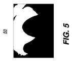
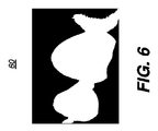
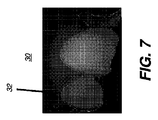
図4〜6は、図2〜3に示される画像のセグメンテーション結果を提供するために利用される2成分閾画像の例を示す。図4は、白で示される歯でも歯茎組織でもない画像コンテンツを伴うバックグラウンド領域画像40を示す。図5は、歯茎組織が白で示される歯茎領域画像50を示す。図6は、歯コンテンツが白で示される歯領域画像60を示す。図7に示されるように、外形32は、歯領域の境界に沿ってトレースされることができ、したがって、例えば境界画像30に表示するための歯の境界を特定する。
4-6 show examples of two-component threshold images that are utilized to provide the segmentation results of the images shown in FIGS. FIG. 4 shows a
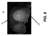
歯の境界が検出されると、場所情報に基づいて、歯の境界は、境界分割ステップS120(図1)で2つのセクションに分割される。その次に、分割された歯の境界に基づいて、特徴が取り出されることが可能である。頬側および舌側表面では、歯の境界分離は、歯茎領域の近傍の第1のセクションおよびバックグラウンド領域の近傍の第2のセクションの、2つのセクションを特定する。図8は、頬側表面の境界分割画像70を示す。境界線74および76は、この表面タイプの異なる境界セクションを示す。線74を境界とする非歯領域は歯茎領域であって、緑色チャネルのより高いピクセル輝度値を有する。線76を境界とする非歯領域は、バックグラウンド領域であって、緑色チャネルのより低いピクセル輝度値を有する。
When a tooth boundary is detected, based on the location information, the tooth boundary is divided into two sections in a boundary dividing step S120 (FIG. 1). Then, features can be retrieved based on the divided tooth boundaries. On the buccal and lingual surfaces, the tooth boundary separation identifies two sections: a first section near the gum region and a second section near the background region. FIG. 8 shows a boundary divided
咬合面では、図9の画像80に示されるように、歯の境界は、歯列の方向に従って、2つのセクションに分割される。1つのセクションが線82で示され、この線に隣接する非歯領域は、緑色チャネルにおいて、より低いピクセル輝度値を有する。他のセクションは、線84でハイライト表示され、この線に隣接する非歯領域は、緑色チャネルにおいて、より高いピクセル輝度値を有する。境界は、歯を横断して画像に沿って変化し得る距離Dで分離される。
At the occlusal surface, the tooth boundary is divided into two sections according to the direction of the dentition, as shown in the
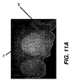
図1の順序を再び参照すると、特徴抽出ステップS130は、歯の表面のさらなる分類のために、境界分割ステップS120の結果をその次に利用する。図10の論理フロー図は、特徴抽出ステップS130で利用される一連のステップを示す。特定ステップS131は、境界分割ステップS120からの、図8の線74で歯茎線に沿って特定された境界等、第1の境界セクションを、例えば特定する。図11Aを参照すると、この第1の境界曲線は、画像拡張等、形態的画像処理手法を利用して、例えば最初に拡張される。これは、線74を拡張し、第1の境界セクション44を画定する。
Referring back to the sequence of FIG. 1, feature extraction step S130 uses the result of boundary segmentation step S120 next for further classification of the tooth surface. The logic flow diagram of FIG. 10 shows a series of steps used in the feature extraction step S130. The specifying step S131 specifies, for example, the first boundary section such as the boundary specified along the gum line by the
図10の順序を続けると、後続のサブステップは、図11Bおよび図11Cに示されるように、第1の境界セクション44を2つの部分に分割する。図11Bは、線74の歯茎組織側に位置するか、またはオーバーラップする、第1の境界セクション44のその部分として、第1の部分46がどのように画定されるかを示す。この部分は、隣接する歯茎領域で平均値または他の統計値として計算される、グレースケール分散値FeaUpperGumを有する。
Continuing with the sequence of FIG. 10, subsequent substeps divide the
図11Cは、線74の歯側にオーバーラップする第1の境界セクション44のその部分として、第2の部分48がどのように画定されかを示す。この部分は、隣接する歯領域で平均値または他の統計値として計算される、グレースケール分散値FeaUpperToothを有する。
FIG. 11C shows how the
これら画定された領域を前提として、第1の比の計算ステップS132は、片側の境界の近傍の歯領域、第2の部分48の平均グレースケール値と、反対側の境界の近傍の歯茎領域、第1の部分46の平均グレースケール値との第1の境界比として計算される値Feature1をその次に計算し、メモリに記憶する、つまり、
Feature1=FeaUpperTooth/FeaUpperGum
であり、または代替では、その逆数として表現される比である。
Feature1b=FeaUpperGum/FeaUpperTooth
Given these defined areas, the first ratio calculation step S132 includes a tooth area near the one-side boundary, an average grayscale value of the
Feature1 = FeaUpperTooth / FeaUpperGum
Or, alternatively, a ratio expressed as its reciprocal.
Feature1b = FeaUpperGum / FeaUpperTooth
本開示の文脈において、特定の場所における「近傍」という用語は、境界間との全距離の3分の1以内、好ましくは、この長さの3分の1よりも近いことを意味する。図9は、境界間の典型的な距離Dを示す。 In the context of this disclosure, the term “neighbor” at a particular location means within one third of the total distance between the boundaries, preferably closer than one third of this length. FIG. 9 shows a typical distance D between the boundaries.
図10の順序を続けると、後続の特定ステップS133は境界分割ステップS120からの、図8の線76でバックグラウンドに沿って特定される境界等、第2の境界セクションを、例えば特定する。図12Aを参照すると、この第2の境界カーブは、最初は、画像拡張等、形態的画像処理手法を利用して、例えば拡張される。これは、線76を拡張し、第2の境界セクション54を画定する。
Continuing with the order of FIG. 10, a subsequent identification step S133 identifies, for example, a second boundary section, such as the boundary identified along the background at
第2の比の計算ステップS134は、片側の境界の近傍の歯領域の平均グレースケール値と、反対側の境界の近傍のバックグラウンド領域の平均グレースケール値との第2の境界比をその次に計算し、メモリに記憶する。図11A、11B、および11Cで示される順序に類似して、図12A、12B、および12Cは、個別の領域がどのように特定されるか図説する。 In the second ratio calculation step S134, the second boundary ratio between the average grayscale value of the tooth region near the one-side boundary and the average grayscale value of the background region near the opposite-side boundary is calculated next. Is calculated and stored in the memory. Similar to the order shown in FIGS. 11A, 11B, and 11C, FIGS. 12A, 12B, and 12C illustrate how individual regions are identified.
図10の順序を続けると、後続のサブステップは、第2の境界セクション54を、図12Bおよび12Cに示されるように、2つの部分に分割する。図12Bは、第1の部分56がどのようにして、線76の歯組織側にあるか、またはオーバーラップする第2の境界セクション54の部分として、画定されるかを示す。この部分は、隣接する歯領域の平均値または他の統計値として計算される、グレースケール分散値FeaLowerToothを有する。
Continuing with the sequence of FIG. 10, a subsequent substep divides the
図12Cは、第2の部分58が、線76のバックグラウンド側にオーバーラップする、第2の境界セクション54の部分として、どのように画定されるかを示す。この部分は、隣接するバックグラウンド領域の平均値または他の統計値として計算される、グレースケール 分散値FeaLowerBackを有する。
FIG. 12C shows how the
これら、画定された領域を前提として、第2の比計算ステップS134は、
Feature2=FeaLowerTooth/FeaLowerBack
として、計算される値Feature2を、または代替では、その逆数として表現される比をその次に計算し、メモリに記憶する。
Feature2b=FeaLowerBack/FeaLowerTooth
Given these defined areas, the second ratio calculation step S134
Feature2 = FeaLowerTooth / FeaLowerBack
As the calculated value Feature2 or, alternatively, the ratio expressed as its reciprocal, and stores it in memory.
Feature2b = FeaLowerBack / FeaLowerTooth
第3の比計算ステップ図10のS136は、第1の境界セクションと第2の境界セクションの近傍の歯領域の平均グレースケール値の比をその次に計算し、記憶する。つまり、
Feature3=FeaUpperTooth/FeaLowerTooth
または代替では、その逆数である。
Feature3b=FeaLowerTooth/FeaUpperTooth
Third Ratio Calculation Step S136 in FIG. 10 then calculates and stores the ratio of the average grayscale values of the tooth regions in the vicinity of the first boundary section and the second boundary section. That means
Feature3 = FeaUpperTooth / FeaLowerTooth
Or alternatively, the reciprocal.
Feature3b = FeaLowerTooth / FeaUpperTooth
3次元特徴ベクトルまたは類似のデータ構造は、先行するステップから計算された比データを利用して、特徴ベクトル生成ステップS138でその次に形成される。生成されたベクトルは、したがって、第1の境界比、第2の境界比、第3の比を含む。このように形成される特徴ベクトルは記憶され、歯の表面の分類のために利用され得る。 A three-dimensional feature vector or similar data structure is then formed in feature vector generation step S138 using the ratio data calculated from the previous step. The generated vector thus includes a first boundary ratio, a second boundary ratio, and a third ratio. The feature vectors thus formed can be stored and used for classification of the tooth surface.
3次元ベクトル構成は、Feature1、Feature2およびFeature3を、または、その逆数を任意の順番で利用できる。代替では、2次元ベクトルが、[Feature1,Feature2]または[Feature2,Feature1]を利用して、形成されることができる。 The three-dimensional vector configuration can use Feature1, Feature2, and Feature3, or their reciprocals in any order. Alternatively, a two-dimensional vector can be formed utilizing [Feature1, Feature2] or [Feature2, Feature1].
選択的ベクトル正規化プロセスは、

分類子ロードステップS140(図1)は、歯の表面の分類の適切な分類子を、ロードする。本発明の一実施形態によれば、分類子ロードステップS140は、このタスクのために、PCA(主成分分析)分類子をロードする。主成分分析(PCA)は、相関関係がある可能性のある観察結果の集合を、主成分と称される線形非相関変数の値の集合に変換する直交変換を利用する数学的手法である。主成分の数は、初期の変数の数以下である。PCA分類子は、分類子ソフトウェアがテストサンプルセットを利用してトレーニングされることを可能にする、ニューラルネットワーク手法を利用して、典型的に開発される。PCA分類ツールが、形状および輪郭分類に特に適している一方で、他の分類子の種類は、代替で利用される可能性がある。分類子が表面の特徴を区別するように、十分にトレーニングされると、患者画像は、分類ステップS150が分析するのに利用するために、その次に記憶される可能性がある。分類は次に、歯画像を、頬側もしくは舌側表面または咬合面画像のいずれかとして画定する。 The classifier loading step S140 (FIG. 1) loads the appropriate classifier for the tooth surface classification. According to one embodiment of the invention, the classifier load step S140 loads a PCA (principal component analysis) classifier for this task. Principal component analysis (PCA) is a mathematical technique that uses orthogonal transformation to transform a set of observations that may be correlated into a set of values of linear uncorrelated variables called principal components. The number of principal components is less than or equal to the number of initial variables. PCA classifiers are typically developed using neural network techniques that allow classifier software to be trained using a set of test samples. While the PCA classification tool is particularly suitable for shape and contour classification, other classifier types may be used alternatively. Once the classifier is sufficiently trained to distinguish surface features, the patient image may then be stored for use by the classification step S150 for analysis. Classification then defines the tooth image as either a buccal or lingual surface or an occlusal surface image.
さらに、図1の手続きの順序に従い、図13に示される展開された論理フローを利用すると、特徴ベクトル90が分類プロセスS150で処理された後、分類が完了されると、齲蝕検出ステップS160はその次に実行される。図13の論理フローに示されるように、齲蝕検出ステップS160は、特定された表面の分類の種類に依存する異なるパラメータまたはアルゴリズムを適用する。結果162が、平滑面を示すときに、齲蝕検出ステップS166は、舌側または表面に適用される。結果164が荒れた表面を示すときに、齲蝕検出ステップS168が、咬合面に適用される。報告ステップS170は、歯の番号および表面を列挙し、または1つ以上の齲蝕部位を、画像化した歯を示すディスプレイコンソール上にハイライト表示する等、齲蝕検出の結果を、例えばその次に報告する。齲蝕検出ステップS160は、図1に示される順序に提供された歯の表面の分類を利用できる画像処理の一種類であることに注意されたい。代替の処理ステップは、歯の外見分析または画像ビューの分類等、他の方法で歯の表面の分類を利用するために、例えば提供され得る。
Further, using the expanded logic flow shown in FIG. 13 in accordance with the order of procedures in FIG. 1, after the
当業者により認められるように、本発明は、システムの一部が、画像を得て表示するため、操作者の命令および入力データを受容するため、ならびに操作者の入力に対して応答するための命令でプログラムされるコンピュータプログラム製品、または他の制御論理プロセッサ機器を利用して実行される、システムまたは方法として実施されてもよい。したがって、本発明の実施形態は、全体にハードウェアの実施形態の形態であってもよく、または、本明細書で「回路」または「システム」としてすべて概して称されてもよい、ソフトウェアとハードウェアの態様を組み合わせる実施形態であってもよい。さらには、本発明の一部は、コンピュータ可読記憶媒体に実施される、1つ以上のコンピュータまたはホストプロセッサで実行される命令を伴う、コンピュータプログラム製品の形式をとってもよい。この媒体は、磁気ディスク(ハードドライブもしくは記憶ディスク等)もしくは磁気テープ等の磁気記憶媒体;光学ディスク、光学テープ、もしくは機械可読なバーコード等の光学記憶媒体;半導体ハードドライブ、ランダムアクセスメモリ(RAM)もしくは読み出し専用メモリ(ROM)等の半導体記憶機器;またはコンピュータプログラムを記憶するのに利用される任意の他の物理的機器もしくは媒体を、例えば含んでもよい。本発明の方法を実行するコンピュータプログラムは、インターネットまたは他の通信媒体でホストプロセッサと接続されるコンピュータ可読媒体に記憶されてもよい。 As will be appreciated by those skilled in the art, the present invention provides a portion of the system for obtaining and displaying images, for accepting operator commands and input data, and for responding to operator input. It may be implemented as a system or method that is executed utilizing a computer program product programmed with instructions, or other control logic processor equipment. Accordingly, embodiments of the present invention may be in the form of hardware embodiments entirely, or software and hardware that may all be generally referred to herein as “circuits” or “systems”. The embodiment which combines these aspects may be sufficient. Furthermore, portions of the present invention may take the form of a computer program product with instructions executed on one or more computers or host processors embodied on a computer-readable storage medium. This medium is a magnetic storage medium such as a magnetic disk (hard drive or storage disk) or magnetic tape; an optical storage medium such as an optical disk, optical tape, or machine-readable barcode; a semiconductor hard drive, a random access memory (RAM) ) Or a read only memory (ROM) or other semiconductor storage device; or any other physical device or medium utilized to store a computer program, for example. A computer program that performs the method of the present invention may be stored on a computer-readable medium connected to a host processor over the Internet or other communication medium.
本開示の文脈では「コンピュータアクセス可能メモリ」と均等である「メモリ」という用語は、例えばデータベースを含む、画像データを記憶し操作するために使用され、コンピュータシステムにアクセス可能である任意の種類の一時的またはより永続的なデータ記憶ワークスペースを指すことができることに注意されたい。メモリは、磁気記憶または光学記憶等、長期間記憶媒体を例えば利用した、非揮発性であり得る。代替では、メモリは、マイクロプロセッサまたは他の制御論理プロセッサ機器で、一時バッファまたはワークスペースとして利用されるランダムアクセスメモリ(RAM)等、電子回路を利用する、より揮発性であり得る。表示データは、表示機器と直接的に関連し、表示されるデータを提供するために、必要に応じて定期的にリフレッシュされる、一時記憶バッファに例えば典型的に記憶される。この一時記憶バッファも、この用語が本開示で使用されるときには、メモリとして見なすことができる。メモリは、計算および他の処理の中間結果および最終結果を実行し、記憶するためのデータワークスペースとしても利用される。コンピュータアクセス可能メモリは、揮発性、非揮発性、または揮発性および非揮発性のタイプのハイブリッドな組み合わせである可能性がある。 The term “memory” that is equivalent to “computer-accessible memory” in the context of this disclosure is used to store and manipulate image data, including, for example, a database, and is of any kind accessible to a computer system. Note that this can refer to a temporary or more permanent data storage workspace. The memory can be non-volatile, for example using a long-term storage medium, such as magnetic storage or optical storage. Alternatively, the memory may be more volatile, utilizing electronic circuitry, such as random access memory (RAM) that is used as a temporary buffer or workspace in a microprocessor or other control logic processor equipment. Display data is typically stored, for example, in a temporary storage buffer that is directly associated with the display device and is periodically refreshed as needed to provide the data to be displayed. This temporary storage buffer can also be considered as memory when the term is used in this disclosure. The memory is also used as a data workspace for executing and storing intermediate and final results of calculations and other processes. Computer-accessible memory can be volatile, non-volatile, or a hybrid combination of volatile and non-volatile types.
当業者は、そのようなコンピュータプログラムの同等なものがハードウェアの内に構成されてもよいことを直ちに認識するであろう。コンピュータ利用可または可読媒体は、例えば紙または他の媒体の光学的スキャンを経由して命令が電子的に捕捉されることが可能で、その次にコンパイルされ、解釈され、または必要ならば好適な方式で処理され、コンピュータのメモリにその次に記憶されるので、実行可能命令がその上にプリントされる紙または別の好適な媒体であってもよい。本明細書の文脈では、コンピュータ利用可またはコンピュータ可読媒体は、命令実行システム、装置、または機器で、または関連して使用されるコンピュータ命令を含み、記憶し、通信し、伝搬し、転送することが可能な任意の媒体であってもよい。 Those skilled in the art will immediately recognize that the equivalent of such a computer program may be configured in hardware. Computer-usable or readable media can be captured, eg, via optical scanning of paper or other media, and then compiled, interpreted, or suitable if necessary Processed in a manner and then stored in the computer's memory, the executable instructions may be paper or another suitable medium printed thereon. In the context of this specification, a computer-usable or computer-readable medium includes, stores, communicates, propagates, and transmits computer instructions used in or in connection with an instruction execution system, apparatus, or device. May be any medium capable of.
本発明は1つ以上の実装について説明されたが、添付の請求項の趣旨および範囲を逸脱せずに、説明した例に変更および/または修正を行うことができる。さらに、複数の実装のうちの1つのみについて本発明の特定の特徴が開示されたが、そのような特徴は、任意の所与のまたは特定の機能にとって所望され、かつ優位性が有り得るように他の実装の1つ以上の他の特徴と組み合わせることができる。 Although the invention has been described in terms of one or more implementations, changes and / or modifications can be made to the examples described without departing from the spirit and scope of the appended claims. Moreover, while specific features of the invention have been disclosed for only one of a plurality of implementations, such features may be desirable and advantageous for any given or specific function. It can be combined with one or more other features of other implementations.
「〜のうちの少なくとも1つ」という用語は、列挙されたアイテムのうちの1つ以上が選択可能であることを意味するように使用される。「約」という用語は、変更が説明された本実施形態に対してプロセスまたは構造で不適合とならない限りにおいて、列挙された値が幾分変更され得ることを示す。最後に、「例示的」は、理想であることを意味するのではなく、説明が例として利用されることを示す。 The term “at least one of” is used to mean that one or more of the listed items are selectable. The term “about” indicates that the listed values can be modified somewhat, as long as the changes do not become incompatible with the process or structure for the described embodiment. Finally, “exemplary” does not mean ideal but indicates that the description is used as an example.
Claims (3)
反射率画像処理手法及び蛍光発光画像処理手法の少なくとも一方により1つ以上の歯のデジタル画像を得るステップと、
前記1つ以上の歯の第1の境界および第2の境界を検出するステップと、
前記第1の境界の片側の歯領域の平均グレースケール値と、前記第1の境界の反対側の非歯領域の平均グレースケール値との第1の比、および、前記第2の境界の片側の歯領域の平均グレースケール値と、前記第2の境界の反対側の非歯領域の平均グレースケール値との第2の比を計算し、計算された前記第1の比および前記第2の比をメモリに記憶するステップと、
前記第1の境界の近傍の前記歯領域の前記平均グレースケール値と、前記第2の境界の近傍の前記歯領域の前記平均グレースケール値との第3の比を計算し、前記第3の比を前記メモリに記憶するステップと、
前記第1の比、前記第2の比、および前記第3の比を用いて、歯の表面を平滑面または咬合面のいずれかに分類するステップと、
前記歯の表面の分類に従って、前記デジタル画像を用いて歯科画像処理および口腔内画像処理の少なくとも一方を実行するステップと、
処理結果を報告するステップと、
を含む、方法。 A method for intraoral image processing, said method being performed at least in part on a computer system;
Obtaining a digital image of one or more teeth by at least one of a reflectance image processing technique and a fluorescence emission image processing technique ;
Detecting a first boundary and a second boundary of the one or more teeth;
Before SL and the average gray scale value of one side of the tooth region of the first boundary, the first ratio between the average gray scale value of the non-tooth region opposite the first boundary, and, of the second boundary Calculating a second ratio between an average grayscale value of one tooth area and an average grayscale value of a non-tooth area opposite the second boundary, and calculating the first ratio and the second Storing the ratio in a memory;
Calculating a third ratio between the average grayscale value of the tooth region near the first boundary and the average grayscale value of the tooth region near the second boundary; Storing the ratio in the memory;
Classifying the surface of the tooth as either a smooth surface or an occlusal surface using the first ratio, the second ratio, and the third ratio ;
Performing at least one of dental image processing and intraoral image processing using the digital image according to the classification of the tooth surface;
Reporting the processing results;
Including the method.
前記平均グレースケール値は、前記第1の境界と第2の境界との間の距離の3分の1以内である前記デジタル画像の部分からのものである、請求項1に記載の方法。 The digital image is a still image or a moving image obtained by an intraoral camera image system,
The method of claim 1, wherein the average grayscale value is from a portion of the digital image that is within one third of the distance between the first boundary and a second boundary.
反射率画像処理手法及び蛍光発光画像処理手法の少なくとも一方により1つ以上の歯のデジタル画像を得るステップと、
前記1つ以上の歯の第1の境界および第2の境界を検出するステップと、
前記第1の境界および第2の境界のそれぞれにおいて、前記境界の片側の歯領域の平均グレースケール値と、前記境界の反対側の非歯領域の平均グレースケール値との境界比を計算し、計算された前記境界比をメモリに記憶するステップと、
前記第1の境界の近傍の前記歯領域の前記平均グレースケール値と、前記第2の境界の近傍の前記歯領域の前記平均グレースケール値との第3の比を計算し、前記第3の比を前記メモリに記憶するステップと、
少なくとも計算された前記境界比および前記第3の比を含むベクトルを形成し、記憶するステップと、
記憶された前記ベクトルに従って、歯の表面を平滑面または咬合面のいずれかに分類するステップと、
前記歯の表面の分類に従って、齲蝕を検出するために前記デジタル画像を処理するステップと、
処理結果をディスプレイ上で報告するステップと、
を含む、方法。 A method for caries detection, wherein the method is performed at least in part on a computer system having a display;
Obtaining a digital image of one or more teeth by at least one of a reflectance image processing technique and a fluorescence emission image processing technique ;
Detecting a first boundary and a second boundary of the one or more teeth;
For each of the first boundary and the second boundary, calculating a boundary ratio between an average grayscale value of a tooth region on one side of the boundary and an average grayscale value of a non-tooth region on the opposite side of the boundary; Storing the calculated boundary ratio in a memory;
Calculating a third ratio between the average grayscale value of the tooth region near the first boundary and the average grayscale value of the tooth region near the second boundary; Storing the ratio in the memory;
Forming and storing a vector including at least the calculated boundary ratio and the third ratio;
Classifying the tooth surface as either smooth or occlusal according to the stored vector;
Processing the digital image to detect caries according to a classification of the tooth surface;
Reporting processing results on the display;
Including the method.
Applications Claiming Priority (3)
| Application Number | Priority Date | Filing Date | Title |
|---|---|---|---|
| US201161454761P | 2011-03-21 | 2011-03-21 | |
| US61/454,761 | 2011-03-21 | ||
| PCT/US2012/029646 WO2012129160A2 (en) | 2011-03-21 | 2012-03-19 | A method for tooth surface classification |
Publications (3)
| Publication Number | Publication Date |
|---|---|
| JP2014509908A JP2014509908A (en) | 2014-04-24 |
| JP2014509908A5 JP2014509908A5 (en) | 2015-04-30 |
| JP6038112B2 true JP6038112B2 (en) | 2016-12-07 |
Family
ID=46879990
Family Applications (1)
| Application Number | Title | Priority Date | Filing Date |
|---|---|---|---|
| JP2014501167A Expired - Fee Related JP6038112B2 (en) | 2011-03-21 | 2012-03-19 | Method for classification of tooth surfaces |
Country Status (7)
| Country | Link |
|---|---|
| US (1) | US9020236B2 (en) |
| EP (1) | EP2688479B1 (en) |
| JP (1) | JP6038112B2 (en) |
| KR (1) | KR101911567B1 (en) |
| CN (1) | CN103442645B (en) |
| ES (1) | ES2692545T3 (en) |
| WO (1) | WO2012129160A2 (en) |
Families Citing this family (31)
| Publication number | Priority date | Publication date | Assignee | Title |
|---|---|---|---|---|
| US8768016B2 (en) * | 2009-06-19 | 2014-07-01 | Carestream Health, Inc. | Method for quantifying caries |
| US9870613B2 (en) * | 2014-11-05 | 2018-01-16 | Carestream Health, Inc. | Detection of tooth condition using reflectance images with red and green fluorescence |
| KR101623356B1 (en) * | 2014-12-31 | 2016-05-24 | 오스템임플란트 주식회사 | Dental implant planning guide method, apparatus and recording medium thereof |
| US9547903B2 (en) * | 2015-04-16 | 2017-01-17 | Carestream Health, Inc. | Method for quantifying caries |
| EP3383311B1 (en) | 2015-12-04 | 2024-07-31 | 3Shape A/S | Deriving tooth condition information for populating digital dental charts |
| EP3459494B1 (en) * | 2016-05-10 | 2022-07-27 | Kambara, Masaki | Dental health assessment assisting system |
| JP2018022260A (en) * | 2016-08-02 | 2018-02-08 | 株式会社オプテック | Image processor |
| CN108243605A (en) * | 2016-10-24 | 2018-07-03 | 深圳市龙岗中心医院 | A kind of maxillary central incisors sorting technique and system |
| DE102017203475A1 (en) * | 2017-03-03 | 2018-09-06 | Sirona Dental Systems Gmbh | Method of constructing a restoration |
| EP3398504A1 (en) * | 2017-05-05 | 2018-11-07 | Koninklijke Philips N.V. | Oral care system to detect localized inflammation |
| CN110769777B (en) * | 2017-06-16 | 2023-08-11 | 阿莱恩技术有限公司 | Automatic detection of tooth type and eruption status |
| EA201700561A1 (en) * | 2017-11-16 | 2019-05-31 | Общество С Ограниченной Ответственностью "Доммар" | METHOD AND SYSTEM OF TEETH ALIGNMENT ON THE BASIS OF MODELING THE CROWN AND ROOTS MOVEMENT |
| US11823376B2 (en) | 2018-05-16 | 2023-11-21 | Benevis Informatics, Llc | Systems and methods for review of computer-aided detection of pathology in images |
| CN112136157B (en) * | 2018-05-29 | 2024-04-26 | 麦迪西姆有限公司 | Method, system and computer program for segmenting the dental pulp region of a tooth based on an image |
| DE102018210259A1 (en) * | 2018-06-22 | 2019-12-24 | Sirona Dental Systems Gmbh | Process for the construction of a drilling template |
| US11389131B2 (en) | 2018-06-27 | 2022-07-19 | Denti.Ai Technology Inc. | Systems and methods for processing of dental images |
| KR102176490B1 (en) | 2018-08-24 | 2020-11-10 | 이재우 | Methods for Segmentation and Processing of Dental Images for Diagnosing, Predicting, or Managing Oral Conditions |
| EP3899972A2 (en) | 2018-12-21 | 2021-10-27 | The Procter & Gamble Company | Apparatus and method for operating a personal grooming appliance or household cleaning appliance |
| EP3967235A4 (en) * | 2019-03-25 | 2022-11-30 | Bonewise Inc. | DEVICE AND METHOD FOR EVALUATION OF BONE AGE OF TEETH AND RECORDING MEDIUM FOR RECORDING INSTRUCTIONS FOR EVALUATION OF BONE AGE |
| CN113692250B (en) * | 2019-04-11 | 2024-07-23 | 株式会社迪耀 | Image data preprocessing device |
| US10984529B2 (en) | 2019-09-05 | 2021-04-20 | Pearl Inc. | Systems and methods for automated medical image annotation |
| US11676701B2 (en) | 2019-09-05 | 2023-06-13 | Pearl Inc. | Systems and methods for automated medical image analysis |
| KR102255592B1 (en) * | 2019-11-19 | 2021-05-25 | 주식회사 레이 | method of processing dental CT images for improving precision of margin line extracted therefrom |
| US11055789B1 (en) | 2020-01-17 | 2021-07-06 | Pearl Inc. | Systems and methods for insurance fraud detection |
| US11978207B2 (en) * | 2021-06-03 | 2024-05-07 | The Procter & Gamble Company | Oral care based digital imaging systems and methods for determining perceived attractiveness of a facial image portion |
| US12340510B2 (en) | 2020-06-04 | 2025-06-24 | The Procter & Gamble Company | Oral care based digital imaging systems and methods for analyzing attributes of a facial image portion |
| AU2021296514A1 (en) * | 2020-06-24 | 2022-06-09 | Oral Tech Ai Pty Ltd | Computer-implemented detection and processing of oral features |
| CN116634915A (en) * | 2020-12-22 | 2023-08-22 | 葛兰素史克消费保健(美国)控股有限责任公司 | Systems and methods for capturing images of teeth and identifying early enamel erosion in teeth |
| US11776677B2 (en) | 2021-01-06 | 2023-10-03 | Pearl Inc. | Computer vision-based analysis of provider data |
| CN113425440A (en) * | 2021-06-24 | 2021-09-24 | 广州华视光学科技有限公司 | System and method for detecting caries and position thereof based on artificial intelligence |
| EP4366656A4 (en) * | 2021-07-06 | 2025-03-26 | Orthodontia Vision Inc. | SYSTEM AND METHOD FOR DETERMINING AN ORTHODONTIC OCCLUSION CLASS |
Family Cites Families (12)
| Publication number | Priority date | Publication date | Assignee | Title |
|---|---|---|---|---|
| JPH0365605A (en) * | 1989-08-03 | 1991-03-20 | Nippon Telegr & Teleph Corp <Ntt> | Measuring method of edge length in digital image |
| WO2005013843A2 (en) * | 2003-08-08 | 2005-02-17 | The Regents Of The Univeristy Of California | Near-infrared transillumination for the imaging of early dental decay |
| US7324661B2 (en) * | 2004-04-30 | 2008-01-29 | Colgate-Palmolive Company | Computer-implemented system and method for automated and highly accurate plaque analysis, reporting, and visualization |
| JP4918383B2 (en) | 2007-03-16 | 2012-04-18 | オリンパス株式会社 | Outline detecting apparatus, outline detecting method and program thereof |
| US8866894B2 (en) * | 2008-01-22 | 2014-10-21 | Carestream Health, Inc. | Method for real-time visualization of caries condition |
| JP4594429B2 (en) * | 2008-06-30 | 2010-12-08 | オリンパス株式会社 | Dental colorimetry apparatus, system, method, and program |
| US8520922B2 (en) * | 2009-01-20 | 2013-08-27 | Carestream Health, Inc. | Method and apparatus for detection of caries |
| US8768016B2 (en) * | 2009-06-19 | 2014-07-01 | Carestream Health, Inc. | Method for quantifying caries |
| US9113799B2 (en) | 2009-07-30 | 2015-08-25 | Telesystems Co., Ltd. | Radiation imaging apparatus and imaging method using radiation |
| DE102011010975A1 (en) * | 2011-02-10 | 2012-08-16 | Martin Tank | Method and analysis system for geometrical analysis of scan data of oral structures |
| US8897902B2 (en) * | 2011-02-18 | 2014-11-25 | 3M Innovative Properties Company | Orthodontic digital setups |
| US8923581B2 (en) * | 2012-03-16 | 2014-12-30 | Carestream Health, Inc. | Interactive 3-D examination of root fractures |
-
2012
- 2012-03-19 CN CN201280014154.5A patent/CN103442645B/en active Active
- 2012-03-19 EP EP12760500.4A patent/EP2688479B1/en active Active
- 2012-03-19 ES ES12760500.4T patent/ES2692545T3/en active Active
- 2012-03-19 WO PCT/US2012/029646 patent/WO2012129160A2/en not_active Ceased
- 2012-03-19 KR KR1020137024437A patent/KR101911567B1/en not_active Expired - Fee Related
- 2012-03-19 JP JP2014501167A patent/JP6038112B2/en not_active Expired - Fee Related
- 2012-03-19 US US14/002,998 patent/US9020236B2/en not_active Expired - Fee Related
Also Published As
| Publication number | Publication date |
|---|---|
| EP2688479B1 (en) | 2018-08-29 |
| KR101911567B1 (en) | 2018-10-24 |
| JP2014509908A (en) | 2014-04-24 |
| CN103442645B (en) | 2016-11-09 |
| EP2688479A4 (en) | 2014-09-10 |
| CN103442645A (en) | 2013-12-11 |
| WO2012129160A2 (en) | 2012-09-27 |
| US9020236B2 (en) | 2015-04-28 |
| US20140037180A1 (en) | 2014-02-06 |
| KR20140012669A (en) | 2014-02-03 |
| WO2012129160A3 (en) | 2012-12-06 |
| ES2692545T3 (en) | 2018-12-04 |
| EP2688479A2 (en) | 2014-01-29 |
Similar Documents
| Publication | Publication Date | Title |
|---|---|---|
| JP6038112B2 (en) | Method for classification of tooth surfaces | |
| EP2312528B1 (en) | Method for identifying a tooth region | |
| KR101646792B1 (en) | Method for quantifying caries | |
| US9870613B2 (en) | Detection of tooth condition using reflectance images with red and green fluorescence | |
| EP2312529B1 (en) | A method for locating an interproximal tooth region | |
| US9547903B2 (en) | Method for quantifying caries | |
| US8908936B2 (en) | Method for extracting a carious lesion area | |
| KR20200023225A (en) | Methods for Segmentation and Processing of Dental Images for Diagnosing, Predicting, or Managing Oral Conditions | |
| Frejlichowski et al. | Automatic segmentation of digital orthopantomograms for forensic human identification |
Legal Events
| Date | Code | Title | Description |
|---|---|---|---|
| A521 | Request for written amendment filed |
Free format text: JAPANESE INTERMEDIATE CODE: A523 Effective date: 20150311 |
|
| A621 | Written request for application examination |
Free format text: JAPANESE INTERMEDIATE CODE: A621 Effective date: 20150311 |
|
| A977 | Report on retrieval |
Free format text: JAPANESE INTERMEDIATE CODE: A971007 Effective date: 20160217 |
|
| A131 | Notification of reasons for refusal |
Free format text: JAPANESE INTERMEDIATE CODE: A131 Effective date: 20160223 |
|
| A521 | Request for written amendment filed |
Free format text: JAPANESE INTERMEDIATE CODE: A523 Effective date: 20160513 |
|
| TRDD | Decision of grant or rejection written | ||
| A01 | Written decision to grant a patent or to grant a registration (utility model) |
Free format text: JAPANESE INTERMEDIATE CODE: A01 Effective date: 20161011 |
|
| A61 | First payment of annual fees (during grant procedure) |
Free format text: JAPANESE INTERMEDIATE CODE: A61 Effective date: 20161101 |
|
| R150 | Certificate of patent or registration of utility model |
Ref document number: 6038112 Country of ref document: JP Free format text: JAPANESE INTERMEDIATE CODE: R150 |
|
| R250 | Receipt of annual fees |
Free format text: JAPANESE INTERMEDIATE CODE: R250 |
|
| R250 | Receipt of annual fees |
Free format text: JAPANESE INTERMEDIATE CODE: R250 |
|
| R250 | Receipt of annual fees |
Free format text: JAPANESE INTERMEDIATE CODE: R250 |
|
| LAPS | Cancellation because of no payment of annual fees |