JP5959539B2 - Orthodontic digital setup - Google Patents
Orthodontic digital setup Download PDFInfo
- Publication number
- JP5959539B2 JP5959539B2 JP2013554630A JP2013554630A JP5959539B2 JP 5959539 B2 JP5959539 B2 JP 5959539B2 JP 2013554630 A JP2013554630 A JP 2013554630A JP 2013554630 A JP2013554630 A JP 2013554630A JP 5959539 B2 JP5959539 B2 JP 5959539B2
- Authority
- JP
- Japan
- Prior art keywords
- tooth
- block
- teeth
- dental arch
- dentition
- Prior art date
- Legal status (The legal status is an assumption and is not a legal conclusion. Google has not performed a legal analysis and makes no representation as to the accuracy of the status listed.)
- Active
Links
- 238000000034 method Methods 0.000 claims description 235
- 210000000214 mouth Anatomy 0.000 claims description 7
- 238000009877 rendering Methods 0.000 claims description 6
- 210000002455 dental arch Anatomy 0.000 description 145
- 230000036346 tooth eruption Effects 0.000 description 136
- 210000004513 dentition Anatomy 0.000 description 134
- 230000033001 locomotion Effects 0.000 description 131
- 230000008569 process Effects 0.000 description 104
- 230000006870 function Effects 0.000 description 52
- 239000013598 vector Substances 0.000 description 42
- 238000013519 translation Methods 0.000 description 37
- 230000014616 translation Effects 0.000 description 37
- 230000008859 change Effects 0.000 description 21
- 230000011218 segmentation Effects 0.000 description 9
- 238000004422 calculation algorithm Methods 0.000 description 8
- 230000009471 action Effects 0.000 description 7
- 230000007547 defect Effects 0.000 description 7
- 238000004519 manufacturing process Methods 0.000 description 7
- 238000012986 modification Methods 0.000 description 7
- 230000004048 modification Effects 0.000 description 7
- 230000002093 peripheral effect Effects 0.000 description 7
- 230000004044 response Effects 0.000 description 7
- 241000282465 Canis Species 0.000 description 6
- 238000004088 simulation Methods 0.000 description 6
- 230000000007 visual effect Effects 0.000 description 6
- 238000004364 calculation method Methods 0.000 description 5
- 238000004590 computer program Methods 0.000 description 5
- 238000001514 detection method Methods 0.000 description 5
- 230000000694 effects Effects 0.000 description 5
- 210000004195 gingiva Anatomy 0.000 description 5
- 238000012545 processing Methods 0.000 description 5
- 230000001105 regulatory effect Effects 0.000 description 5
- 210000001519 tissue Anatomy 0.000 description 5
- 230000008901 benefit Effects 0.000 description 4
- 210000004763 bicuspid Anatomy 0.000 description 4
- 238000003860 storage Methods 0.000 description 4
- 206010061274 Malocclusion Diseases 0.000 description 3
- 230000015572 biosynthetic process Effects 0.000 description 3
- 238000012790 confirmation Methods 0.000 description 3
- 238000010586 diagram Methods 0.000 description 3
- 239000007943 implant Substances 0.000 description 3
- 230000003993 interaction Effects 0.000 description 3
- 210000001847 jaw Anatomy 0.000 description 3
- 230000013011 mating Effects 0.000 description 3
- 230000009467 reduction Effects 0.000 description 3
- 238000005070 sampling Methods 0.000 description 3
- 238000012935 Averaging Methods 0.000 description 2
- 239000000853 adhesive Substances 0.000 description 2
- 230000001070 adhesive effect Effects 0.000 description 2
- 230000001055 chewing effect Effects 0.000 description 2
- 238000005056 compaction Methods 0.000 description 2
- 238000003745 diagnosis Methods 0.000 description 2
- 238000005516 engineering process Methods 0.000 description 2
- 238000007689 inspection Methods 0.000 description 2
- 239000000523 sample Substances 0.000 description 2
- FHVDTGUDJYJELY-UHFFFAOYSA-N 6-{[2-carboxy-4,5-dihydroxy-6-(phosphanyloxy)oxan-3-yl]oxy}-4,5-dihydroxy-3-phosphanyloxane-2-carboxylic acid Chemical compound O1C(C(O)=O)C(P)C(O)C(O)C1OC1C(C(O)=O)OC(OP)C(O)C1O FHVDTGUDJYJELY-UHFFFAOYSA-N 0.000 description 1
- 241000282412 Homo Species 0.000 description 1
- 208000006650 Overbite Diseases 0.000 description 1
- 241001024096 Uleiota Species 0.000 description 1
- 229940072056 alginate Drugs 0.000 description 1
- 229920000615 alginic acid Polymers 0.000 description 1
- 235000010443 alginic acid Nutrition 0.000 description 1
- 238000004458 analytical method Methods 0.000 description 1
- 210000003484 anatomy Anatomy 0.000 description 1
- 239000005557 antagonist Substances 0.000 description 1
- 230000005540 biological transmission Effects 0.000 description 1
- 238000005266 casting Methods 0.000 description 1
- 230000009194 climbing Effects 0.000 description 1
- 238000004040 coloring Methods 0.000 description 1
- 230000000295 complement effect Effects 0.000 description 1
- 238000010205 computational analysis Methods 0.000 description 1
- 238000002591 computed tomography Methods 0.000 description 1
- 238000012937 correction Methods 0.000 description 1
- 210000004489 deciduous teeth Anatomy 0.000 description 1
- 238000011156 evaluation Methods 0.000 description 1
- 230000001815 facial effect Effects 0.000 description 1
- 238000002594 fluoroscopy Methods 0.000 description 1
- 230000005484 gravity Effects 0.000 description 1
- 210000003128 head Anatomy 0.000 description 1
- 210000004283 incisor Anatomy 0.000 description 1
- 230000002452 interceptive effect Effects 0.000 description 1
- 230000001788 irregular Effects 0.000 description 1
- 238000012804 iterative process Methods 0.000 description 1
- 239000003550 marker Substances 0.000 description 1
- 239000000463 material Substances 0.000 description 1
- 238000013421 nuclear magnetic resonance imaging Methods 0.000 description 1
- 230000002085 persistent effect Effects 0.000 description 1
- 230000004962 physiological condition Effects 0.000 description 1
- 230000006461 physiological response Effects 0.000 description 1
- 229920003023 plastic Polymers 0.000 description 1
- -1 polyvinylsiloxane Polymers 0.000 description 1
- 238000003825 pressing Methods 0.000 description 1
- 230000002265 prevention Effects 0.000 description 1
- 239000000047 product Substances 0.000 description 1
- 230000008439 repair process Effects 0.000 description 1
- 238000011160 research Methods 0.000 description 1
- 238000012552 review Methods 0.000 description 1
- 238000005096 rolling process Methods 0.000 description 1
- 238000000926 separation method Methods 0.000 description 1
- 239000013589 supplement Substances 0.000 description 1
- 210000001738 temporomandibular joint Anatomy 0.000 description 1
- 238000012360 testing method Methods 0.000 description 1
- 230000001225 therapeutic effect Effects 0.000 description 1
- 210000004357 third molar Anatomy 0.000 description 1
- 230000036339 tooth positioning Effects 0.000 description 1
- 238000012285 ultrasound imaging Methods 0.000 description 1
- 238000012800 visualization Methods 0.000 description 1
Images


Classifications
-
- A—HUMAN NECESSITIES
- A61—MEDICAL OR VETERINARY SCIENCE; HYGIENE
- A61C—DENTISTRY; APPARATUS OR METHODS FOR ORAL OR DENTAL HYGIENE
- A61C7/00—Orthodontics, i.e. obtaining or maintaining the desired position of teeth, e.g. by straightening, evening, regulating, separating, or by correcting malocclusions
- A61C7/002—Orthodontic computer assisted systems
-
- G—PHYSICS
- G06—COMPUTING; CALCULATING OR COUNTING
- G06T—IMAGE DATA PROCESSING OR GENERATION, IN GENERAL
- G06T19/00—Manipulating 3D models or images for computer graphics
-
- G—PHYSICS
- G16—INFORMATION AND COMMUNICATION TECHNOLOGY [ICT] SPECIALLY ADAPTED FOR SPECIFIC APPLICATION FIELDS
- G16B—BIOINFORMATICS, i.e. INFORMATION AND COMMUNICATION TECHNOLOGY [ICT] SPECIALLY ADAPTED FOR GENETIC OR PROTEIN-RELATED DATA PROCESSING IN COMPUTATIONAL MOLECULAR BIOLOGY
- G16B5/00—ICT specially adapted for modelling or simulations in systems biology, e.g. gene-regulatory networks, protein interaction networks or metabolic networks
-
- A—HUMAN NECESSITIES
- A61—MEDICAL OR VETERINARY SCIENCE; HYGIENE
- A61C—DENTISTRY; APPARATUS OR METHODS FOR ORAL OR DENTAL HYGIENE
- A61C7/00—Orthodontics, i.e. obtaining or maintaining the desired position of teeth, e.g. by straightening, evening, regulating, separating, or by correcting malocclusions
- A61C7/002—Orthodontic computer assisted systems
- A61C2007/004—Automatic construction of a set of axes for a tooth or a plurality of teeth
-
- G—PHYSICS
- G06—COMPUTING; CALCULATING OR COUNTING
- G06T—IMAGE DATA PROCESSING OR GENERATION, IN GENERAL
- G06T2210/00—Indexing scheme for image generation or computer graphics
- G06T2210/41—Medical
-
- G—PHYSICS
- G16—INFORMATION AND COMMUNICATION TECHNOLOGY [ICT] SPECIALLY ADAPTED FOR SPECIFIC APPLICATION FIELDS
- G16H—HEALTHCARE INFORMATICS, i.e. INFORMATION AND COMMUNICATION TECHNOLOGY [ICT] SPECIALLY ADAPTED FOR THE HANDLING OR PROCESSING OF MEDICAL OR HEALTHCARE DATA
- G16H50/00—ICT specially adapted for medical diagnosis, medical simulation or medical data mining; ICT specially adapted for detecting, monitoring or modelling epidemics or pandemics
- G16H50/50—ICT specially adapted for medical diagnosis, medical simulation or medical data mining; ICT specially adapted for detecting, monitoring or modelling epidemics or pandemics for simulation or modelling of medical disorders
Description
デジタル的に実現される歯科矯正法、及びより詳細には歯科矯正診断及び治療を支援するためのコンピュータを用いた方法を提供する。 A digitally implemented orthodontic method, and more particularly, a computer-based method for supporting orthodontic diagnosis and treatment is provided.
歯科矯正の分野は、機能及び美的外観を改善するために患者の歯群の位置を治すことに関する。例えば歯科矯正治療では、患者の前歯、犬歯、及び小臼歯に固定される、ブラケットとして知られる小さな溝付き装置がしばしば使用される。各ブラケットの溝に受容されるアーチワイヤが、望ましい向きに歯群の動きを案内するための軌道として機能する。アーチワイヤの端部は、患者の大臼歯に固定される、バッカルチューブとして知られる装置に通常は受容される。アーチワイヤ及び各装置は一般的に「ブレース」と呼ばれている。歯科矯正治療は、透明なプラスチック製の歯の位置決めトレイ又は他の機能的装置によって行うこともできる。 The field of orthodontics relates to curing the position of a patient's teeth to improve function and aesthetic appearance. For example, orthodontic treatment often uses small fluted devices known as brackets that are secured to the patient's anterior, canine and premolars. The archwire received in each bracket groove serves as a track to guide the movement of the teeth in the desired orientation. The end of the archwire is normally received in a device known as a buccal tube that is secured to the patient's molar teeth. The archwire and each device are generally called “braces”. Orthodontic treatment can also be performed by a transparent plastic tooth positioning tray or other functional device.
従来、歯科矯正行為は、特定の患者に合った適正な装置の選択、口腔内への装置の配置、及び治療全体を通じた装置の調節などの手で行われる工程に頼っていた。より最近では、技術の進歩にともないこれらの工程の一部は、コンピュータの使用によって支援されるようになりつつある。例えば、コンピュータを使用して個々の患者の歯群の配置を表すデータの取得を案内することができる。次いでこのデータを用いて患者の歯列を視覚化し、治療の任意の段階において歯科矯正治療の計画を診断して支援することができる。更に、これらのデータは、患者に合わせてカスタマイズされたブラケットなどの装置の製造に使用することができる。 Traditionally, orthodontic action has relied on manual processes such as selecting the right device for a particular patient, placing the device in the oral cavity, and adjusting the device throughout the treatment. More recently, as technology advances, some of these processes are being supported by the use of computers. For example, a computer can be used to guide the acquisition of data representing the placement of individual patient teeth. This data can then be used to visualize the patient's dentition and diagnose and assist in orthodontic treatment planning at any stage of treatment. Furthermore, these data can be used in the manufacture of devices such as brackets customized for the patient.
カスタマイズされた装置を使用することには多くの利点がある。第1に、装置の処方によって、不正咬合した歯群の開始位置のばらつきに対応し、歯群へのより効率的な力の伝達が可能となる。第2に、歯科矯正アーチワイヤ又はブラケットベースがカスタマイズされることにより、アーチワイヤが歯群の表面の外形とより密接に一致しうるために大幅に高さの低いブラケットの使用が可能となる。これにより、特に舌側装置において、患者の快適性が向上する。第3に、接着面の形状を歯群の表面に対して正確に相補的となるように製造することで装置の接着を助け、接着の信頼性を最大に高めることができる。 There are many advantages to using customized equipment. First, the prescription of the device allows for more efficient transmission of force to the tooth group in response to variations in the starting position of the tooth group that has been maloccluded. Second, the orthodontic archwire or bracket base can be customized to allow the use of brackets that are significantly lower in height because the archwire can more closely match the profile of the surface of the teeth. This improves patient comfort, particularly in lingual devices. Thirdly, manufacturing the adhesive surface so that the shape of the adhesive surface is exactly complementary to the surface of the tooth group can help to adhere the device and maximize the reliability of the adhesion.
歯群の形状を表す未処理のデータがコンピュータによって受信される場合、データは3次元(3D)空間内の点群にすぎないことがしばしばである。通常、この点群は、1以上の歯、歯肉組織、及び他の周囲の口腔構造を含む患者の歯列の3Dオブジェクトモデルを形成するために表面処理される。このデータが歯科矯正診断及び治療において有用であるためには、個々の歯を表す1以上の別個の動かすことが可能な3Dオブジェクトモデルを生成するために歯列の表面は一般的に「セグメント化」される。これらの歯群モデルは歯肉から別のオブジェクトとして分離されることが更に好ましい。 When raw data representing the shape of a tooth group is received by a computer, the data is often only a point cloud in three-dimensional (3D) space. Typically, this point cloud is surface treated to form a 3D object model of the patient's dentition that includes one or more teeth, gingival tissue, and other surrounding oral structures. In order for this data to be useful in orthodontic diagnosis and treatment, the surface of the dentition is generally “segmented” to generate one or more separate movable 3D object models representing individual teeth. " More preferably, these dentition models are separated from the gingiva as separate objects.
セグメント化によって、使用者は、歯群の配列を一群の個々のオブジェクトとして特性評価し、操作することが可能となる。有利な点として、これらのモデルからアーチ長さ、咬合設定、及び更にはABO評価などの診断情報を導出することが可能である。更なる利点として、デジタル歯科矯正セットアップにより、製造工程における柔軟性を与えることができる。物理的プロセスをデジタルプロセスで置き換えることによって、データ取得工程とデータ操作工程とを、歯型又は印象をある場所から別の場所へ輸送する必要なく、別々の場所で実行することが可能である。物理的物体をあちこちに輸送する必要を低減又はなくすことにより、顧客及びカスタマイズされた装置の製造者の両者にとって大幅なコストの節減につながりうる。 Segmentation allows the user to characterize and manipulate the array of teeth as a group of individual objects. Advantageously, diagnostic information such as arch length, occlusal settings, and even ABO evaluation can be derived from these models. As a further advantage, the digital orthodontic setup can provide flexibility in the manufacturing process. By replacing the physical process with a digital process, the data acquisition and data manipulation steps can be performed at different locations without having to transport the tooth mold or impression from one location to another. By reducing or eliminating the need to transport physical objects around, it can lead to significant cost savings for both customers and customized equipment manufacturers.
デジタル的に実現された歯科矯正法の技術的に困難な側面の一部は、セグメント化プロセスにおける歯のオブジェクトとしての適正な認識に関するものである。歯群は大きさ及び形状に大きなばらつきが見られる傾向があり、コンピュータが特定の歯と隣の歯、及び歯肉組織などの他の周辺構造とを区別することが困難になっている。特に問題となるのは、ぎざぎざで摩耗があり、予測不能でありうる歯の咀嚼面である。これらは、歯の表面を周辺構造から自動的に区別しようとするコンピュータによる動作の妨げとなりうる。ヒトは1本の歯に属する表面を容易に区別することが可能であるが、ヒトがアーチ全体のセグメント化プロセスを手動で行うことは時間がかかる作業となりうる。 Some of the technically difficult aspects of digitally implemented orthodontics relate to proper recognition of teeth as teeth objects in the segmentation process. Tooth groups tend to show large variations in size and shape, making it difficult for computers to distinguish between a specific tooth and the neighboring teeth and other peripheral structures such as gingival tissue. Of particular concern is the chewing surface of teeth, which can be jagged and worn and can be unpredictable. These can interfere with computer operations that attempt to automatically distinguish the tooth surface from surrounding structures. Although humans can easily distinguish surfaces belonging to a single tooth, it can be time consuming for a human to manually perform the entire arch segmentation process.
この問題は、口腔表面上の1本の歯の少なくとも一部を識別するために仮想表面を使用する2工程の方法を用いることによって軽減することが可能である。仮想表面が画定された時点で、口腔表面の残りの部分が自動的に分析されて歯の表面を周囲の口腔表面から分離する境界が識別されることにより、セグメント化された歯オブジェクトが画定される。この方法は、1本の歯の部分であることが既に分かっている口腔表面の部分を除外することにより、半自動的なプロセスの利点は維持しつつ使用者の認識を高める。コンピュータ化されたセグメント化の成功率は、エラーを誘導しやすいクラウンを除外することによって大幅に高くなる。更に、このような計算は、それぞれの連続した歯が識別された後で、分析される口腔表面の面積を減少させることによって大幅に加速される。 This problem can be mitigated by using a two-step method that uses a virtual surface to identify at least a portion of a tooth on the oral surface. Once the virtual surface is defined, the rest of the oral surface is automatically analyzed to identify the boundaries that separate the tooth surface from the surrounding oral surface, thereby defining the segmented tooth object. The This method increases the user's awareness while maintaining the benefits of a semi-automatic process by excluding portions of the oral surface that are already known to be part of a single tooth. The success rate of computerized segmentation is greatly increased by excluding crowns that are prone to error. Further, such calculations are greatly accelerated by reducing the area of the oral surface being analyzed after each successive tooth is identified.
一態様では、歯の歯肉縁を認識するための、コンピュータにより実行される方法が提供される。該方法は、前記コンピュータ内に、少なくとも1本の歯を含む口腔の少なくとも一部の3次元表面をデジタル的に定義する表面モデルデータを受信することと、前記表面モデルデータのレンダリングをユーザインターフェースに提示することと、前記レンダリングされた表面モデル上に歯と関連付けられた所定の点を指定する入力データを受信することと、前記コンピュータのプロセッサを用いて、前記入力データに基づいて前記歯の表面モデル上に外周を導出することと、前記コンピュータのプロセッサを用いて、前記3次元表面に沿った前記外周上の各点から外側に延びる複数の経路に沿って前記表面モデルを分析することによって、前記歯の表面と周辺の口腔の表面とを分離する表面モデルに境界を画定するデータである歯肉縁データを生成することと、を含む。 In one aspect, a computer-implemented method for recognizing the gingival margin of a tooth is provided. The method includes receiving in the computer surface model data that digitally defines a three-dimensional surface of at least a portion of the oral cavity including at least one tooth, and rendering the surface model data to a user interface. Presenting, receiving input data specifying a predetermined point associated with a tooth on the rendered surface model, and using a processor of the computer, based on the input data, the surface of the tooth Deriving a perimeter on the model and using the computer processor to analyze the surface model along a plurality of paths extending outwardly from points on the perimeter along the three-dimensional surface; Gingival margin data, which is data that delimits a surface model that separates the tooth surface from the surrounding oral cavity surface Including generation and that you, the.
別の態様では、仮想の歯に対する歯の座標系を定義する、コンピュータにより実行される方法であって、デジタルディスプレイのユーザインターフェースに仮想の歯を提示することと、前記仮想の歯上に所定の点を定義する点入力データを受信することと、前記仮想の歯と関連付けられた第1及び第2の軸を定義する軸入力データを受信することと、コンピュータのプロセッサを用いて、前記点の周辺の前記歯の表面の部分に対するほぼ法線となるベクトルを計算することと、前記軸入力及び前記計算されたベクトルに基づいて前記歯の座標系を計算することと、を含む、方法が提供される。 In another aspect, a computer-implemented method for defining a coordinate system of a tooth with respect to a virtual tooth, presenting the virtual tooth on a user interface of a digital display; Receiving point input data defining a point; receiving axis input data defining first and second axes associated with the virtual tooth; using a processor of the computer; Calculating a vector that is substantially normal to a peripheral portion of the tooth surface and calculating the coordinate system of the tooth based on the axis input and the calculated vector. Is done.
更に別の態様では、第1の仮想の歯と第2の仮想の歯との間の衝突をシミュレートする、コンピュータにより実行される方法であって、前記コンピュータ内に、3次元空間において前記第1の仮想の歯及び前記第2の仮想の歯を定義するデジタルデータを受信することと、第1の軸に沿った、又は第1の軸を中心とした前記第1の仮想の歯の許容される運動に関する許容される運動入力データを受信することと、コンピュータのプロセッサを用いて、3次元空間において、前記許容される運動入力データに基づいて前記第1の仮想の歯の運動を規制しつつ、前記第1の仮想の歯を前記第2の仮想の歯と接触させることをシミュレートすることと、ディスプレイのユーザインターフェースに、前記シミュレーションから得られたデータを表示することと、を含む、方法が提供される。 In yet another aspect, a computer-implemented method for simulating a collision between a first virtual tooth and a second virtual tooth, the computer comprising the first virtual tooth in a three-dimensional space. Receiving digital data defining one virtual tooth and the second virtual tooth, and accepting the first virtual tooth along or about the first axis Receiving acceptable movement input data relating to the movement being performed and using a computer processor to regulate movement of the first virtual tooth in a three-dimensional space based on the permitted movement input data While simulating contacting the first virtual tooth with the second virtual tooth and displaying the data obtained from the simulation on the user interface of the display. Comprising it and a method are provided.
更に別の態様では、第1の歯列弓と第2の歯列弓との間の衝突をシミュレートする、コンピュータにより実行される方法であって、前記コンピュータ内に、3次元空間において前記第1の仮想の歯列弓及び前記第2の仮想の歯列弓を定義するデジタルデータを受信することと、第1の軸に沿った、又は第1の軸を中心とした前記第1の仮想の歯列弓の許容される運動に関する許容される運動入力データを受信することと、コンピュータのプロセッサを用いて、3次元空間において、前記許容される運動入力データに基づいて前記第1の仮想の歯列弓の運動を規制しつつ、前記第1の仮想の歯列弓を前記第2の仮想の歯列弓と接触させることをシミュレートすることと、ディスプレイのユーザインターフェースに、前記シミュレーションから得られたデータを表示することと、を含む、方法が提供される。
(項目1)
歯の歯肉縁を認識するための、コンピュータにより実行される方法であって、
前記コンピュータ内に、少なくとも1本の歯を含む口腔の少なくとも一部の3次元表面をデジタル的に画定する表面モデルデータを受信することと、
前記表面モデルデータのレンダリングをユーザインターフェースに提示することと、
前記レンダリングされた表面モデル上に歯と関連付けられた所定の点を指定する入力データを受信することと、
前記コンピュータのプロセッサを用いて、前記入力データに基づいて前記歯の前記表面モデル上に外周を導出することと、
前記コンピュータのプロセッサを用いて、3次元表面に沿った前記外周上の各点から外側に延びる複数の経路に沿って前記表面モデルを分析することによって、前記歯の表面と周辺の口腔の表面とを分離する表面モデルに境界を画定するデータである歯肉縁データを生成することと、を含む、方法。
(項目2)
前記ユーザインターフェースに、前記歯肉縁データと関連付けられた、前記表面モデルのレンダリング上の視覚的標示を提示することを更に含む、項目1に記載のコンピュータにより実行される方法。
(項目3)
前記外周が前記表面モデル上の閉鎖経路である、項目1に記載のコンピュータにより実行される方法。
(項目4)
前記歯の前記表面モデルと交差する幾何学的形状を指定する更なる入力データを受信することを更に含み、
前記外周が、前記幾何学的形状と前記表面モデルとの交点に基づいて導出され、前記点が前記外周内にある、項目1に記載のコンピュータにより実行される方法。
(項目5)
前記幾何学的形状が閉鎖表面である、項目4に記載のコンピュータにより実行される方法。
(項目6)
前記外周がフリーハンドのユーザ入力によって画定される、項目1に記載のコンピュータにより実行される方法。
(項目7)
前記歯の前記表面モデルと交差する仮想の補助表面を指定する更なる入力データを受信することを更に含み、
前記外周が、前記補助表面と前記表面モデルとがどこで互いに交差するかに基づいて導出され、前記外周が前記点を包囲する、項目1に記載のコンピュータにより実行される方法。
(項目8)
前記補助表面が球面を含む、項目7に記載の方法。
(項目9)
前記球面が、前記指定された点の周囲にほぼ対称的に配置される、項目8に記載の方法。
(項目10)
歯の種類を指定するユーザ入力を受信することを更に含み、前記仮想の補助表面が、前記指定された歯の種類にしたがって変化する所定の直径を有する、項目7に記載の方法。
(項目11)
仮想の歯に対する歯の座標系を画定する、コンピュータにより実行される方法であって、
デジタルディスプレイのユーザインターフェースに仮想の歯を提示することと、
前記仮想の歯上に所定の点を画定する点入力データを受信することと、
前記仮想の歯と関連付けられた第1及び第2の軸を画定する軸入力データを受信することと、
コンピュータのプロセッサを用いて、前記点の周辺の前記歯の表面の部分に対するほぼ法線となるベクトルを計算することと、
前記軸入力及び前記計算されたベクトルに基づいて前記歯の座標系を計算することと、を含む、コンピュータにより実行される方法。
(項目12)
使用者から、前記歯の座標系と関連付けられた前記仮想の歯に対する改変データを受信することと、
前記改変データと一致するように前記ユーザインターフェースを更新することと、を更に含む、項目11に記載のコンピュータにより実行される方法。
(項目13)
前記改変データが、前記仮想の歯を変形させることに関連付けられた入力を含む、項目11に記載のコンピュータにより実行される方法。
(項目14)
前記改変データが、前記仮想の歯に装置を取り付けることに関連付けられた入力を含む、項目11に記載のコンピュータにより実行される方法。
(項目15)
前記ユーザインターフェースにクロスヘアを提示し、使用者からの入力に基づいて、前記仮想の歯に対する前記クロスヘアの向きに使用者が満足するまで前記クロスヘアを回転させることを更に含み、結果として得られる回転されたクロスヘアの基礎が前記軸入力を含む、項目11に記載のコンピュータにより実行される方法。
(項目16)
前記第1の軸と第2の軸との見かけの交点が、前記仮想の歯上に所定の点を画定するために用いられる、項目11に記載のコンピュータにより実行される方法。
(項目17)
前記ユーザインターフェース内の前記座標系と関連付けられた視覚的標示を標示することを更に含む、項目11に記載のコンピュータにより実行される方法。
(項目18)
前記視覚的標示が、前記歯の座標系のx、y、及びz軸の表現を含む、項目17に記載のコンピュータにより実行される方法。
(項目19)
前記視覚的標示が、歯の近心−遠心、頬唇−舌、及び咬合−歯肉軸の表現を含む、項目17に記載のコンピュータにより実行される方法。
(項目20)
第1の仮想の歯と第2の仮想の歯との間の衝突をシミュレートする、コンピュータにより実行される方法であって、
前記コンピュータ内に、3次元空間において前記第1の仮想の歯及び前記第2の仮想の歯を画定するデジタルデータを受信することと、
第1の軸に沿った、又は第1の軸を中心とした前記第1の仮想の歯の許容される運動に関する許容される運動入力データを受信することと、
コンピュータのプロセッサを用いて、3次元空間において、前記許容される運動入力データに基づいて前記第1の仮想の歯の運動を規制しつつ、前記第1の仮想の歯を前記第2の仮想の歯と接触させることをシミュレートすることと、
ディスプレイのユーザインターフェースに、前記シミュレーションから得られたデータを表示することと、を含む、コンピュータにより実行される方法。
(項目21)
前記結果として得られるデータが、前記シミュレーションから得られる第1及び第2の仮想の歯の位置の一方又は両方の3次元レンダリングを含む、項目20に記載のコンピュータにより実行される方法。
(項目22)
前記許容される運動入力データを用いて、それに沿った、又はそれを中心とした前記第1の歯の運動が許容される第2の軸を画定する、項目20に記載のコンピュータにより実行される方法。
(項目23)
前記第2の軸が、それに沿った、又はそれを中心とした前記第1の歯の運動が規制される軸である、項目22に記載のコンピュータにより実行される方法。
(項目24)
シミュレートすることが、前記第2の軸に沿って、又は前記第2の軸を中心として加えられる力をシミュレートすることを含む、項目22又は23に記載のコンピュータにより実行される方法。
(項目25)
前記シミュレーションが、前記第2の軸に沿った、又は前記第2の軸を中心とした前記第1の仮想の歯又は前記第2の仮想の歯の運動を制限する、項目24に記載のコンピュータにより実行される方法。
(項目26)
前記第2の軸が顆頭軸である、項目22又は23に記載のコンピュータにより実行される方法。
(項目27)
第1の歯列弓と第2の歯列弓との間の衝突をシミュレートする、コンピュータにより実行される方法であって、
前記コンピュータ内に、3次元空間において前記第1の仮想の歯列弓及び前記第2の仮想の歯列弓を画定するデジタルデータを受信することと、
第1の軸に沿った、又は第1の軸を中心とした前記第1の仮想の歯列弓の許容される運動に関する許容される運動入力データを受信することと、
前記コンピュータのプロセッサを用いて、3次元空間において、前記許容される運動入力データに基づいて前記第1の仮想の歯列弓の運動を規制しつつ、前記第1の仮想の歯列弓を前記第2の仮想の歯列弓と接触させることをシミュレートすることと、
ディスプレイのユーザインターフェースに、前記シミュレーションから得られたデータを表示することと、を含む、コンピュータにより実行される方法。
In yet another aspect, a computer-implemented method for simulating a collision between a first dental arch and a second dental arch, wherein the method is implemented in a three-dimensional space within the computer. Receiving digital data defining one virtual dental arch and the second virtual dental arch, and the first virtual along or about the first axis Receiving allowable motion input data relating to allowable motion of the dental arch and using a computer processor in a three-dimensional space based on the allowable motion input data Simulating the contact of the first virtual dental arch with the second virtual dental arch while regulating the movement of the dental arch, and a display user interface obtained from the simulation Including the and displaying the data, a method is provided.
(Item 1)
A computer-implemented method for recognizing the gingival margin of a tooth, comprising:
Receiving in the computer surface model data that digitally defines a three-dimensional surface of at least a portion of the oral cavity including at least one tooth;
Presenting a rendering of the surface model data to a user interface;
Receiving input data specifying predetermined points associated with teeth on the rendered surface model;
Deriving an outer circumference on the surface model of the tooth based on the input data using a processor of the computer;
Analyzing the surface model along a plurality of paths extending outwardly from each point on the circumference along a three-dimensional surface using the computer's processor; Generating gingival margin data that is data defining a boundary to a surface model that separates.
(Item 2)
The computer-implemented method of
(Item 3)
The computer-implemented method of
(Item 4)
Further comprising receiving further input data specifying a geometry that intersects the surface model of the tooth;
The computer-implemented method of
(Item 5)
(Item 6)
The computer-implemented method of
(Item 7)
Further comprising receiving further input data specifying a virtual auxiliary surface that intersects the surface model of the tooth;
The computer-implemented method of
(Item 8)
8. A method according to
(Item 9)
9. A method according to
(Item 10)
8. The method of
(Item 11)
A computer-implemented method for defining a tooth coordinate system for a virtual tooth, comprising:
Presenting virtual teeth on the digital display user interface;
Receiving point input data defining a predetermined point on the virtual tooth;
Receiving axis input data defining first and second axes associated with the virtual tooth;
Using a computer processor to calculate a vector that is approximately normal to the portion of the tooth surface around the point;
Computing the coordinate system of the tooth based on the axis input and the calculated vector.
(Item 12)
Receiving from a user modification data for the virtual tooth associated with the tooth coordinate system;
12. The computer-implemented method of item 11, further comprising updating the user interface to match the modified data.
(Item 13)
The computer-implemented method of claim 11, wherein the modification data includes an input associated with deforming the virtual tooth.
(Item 14)
The computer-implemented method of claim 11, wherein the modification data includes input associated with attaching a device to the virtual tooth.
(Item 15)
Presenting the crosshair to the user interface and further comprising rotating the crosshair based on input from the user until the user is satisfied with the orientation of the crosshair relative to the virtual tooth, resulting in rotation The computer-implemented method of claim 11, wherein a crosshair basis includes the axis input.
(Item 16)
(Item 17)
The computer-implemented method of claim 11, further comprising marking a visual marking associated with the coordinate system in the user interface.
(Item 18)
18. The computer-implemented method of item 17, wherein the visual indication includes a representation of the x, y, and z axes of the tooth coordinate system.
(Item 19)
18. The computer-implemented method of item 17, wherein the visual indication includes a mesial-distal tooth, a buccal lip-tongue, and an occlusal-gingival axis representation.
(Item 20)
A computer implemented method for simulating a collision between a first virtual tooth and a second virtual tooth, comprising:
Receiving in the computer digital data defining the first virtual tooth and the second virtual tooth in a three-dimensional space;
Receiving allowable motion input data relating to allowable motion of the first virtual tooth along or about the first axis;
Using a computer processor, the first virtual tooth is moved to the second virtual tooth in a three-dimensional space while regulating the movement of the first virtual tooth based on the allowable movement input data. Simulating contact with teeth;
Displaying the data obtained from the simulation on a user interface of a display.
(Item 21)
21. The computer-implemented method of
(Item 22)
21. The computer-implemented item of
(Item 23)
23. The computer-implemented method of item 22, wherein the second axis is an axis along which or about the movement of the first tooth is regulated.
(Item 24)
24. A computer-implemented method according to item 22 or 23, wherein simulating includes simulating a force applied along or about the second axis.
(Item 25)
Item 25. The computer of item 24, wherein the simulation limits movement of the first virtual tooth or the second virtual tooth along or about the second axis. The method performed by.
(Item 26)
24. A computer-implemented method according to item 22 or 23, wherein the second axis is the condylar axis.
(Item 27)
A computer-implemented method for simulating a collision between a first dental arch and a second dental arch, comprising:
Receiving in the computer digital data defining the first virtual dental arch and the second virtual dental arch in a three-dimensional space;
Receiving allowable motion input data relating to allowable motion of the first virtual dental arch along or about the first axis;
Using the processor of the computer, the movement of the first virtual dental arch is regulated in the three-dimensional space based on the allowable movement input data, and the first virtual dental arch is Simulating contacting with a second virtual dental arch;
Displaying the data obtained from the simulation on a user interface of a display.
図1Aは、クライアントコンピュータ12を含む代表的なコンピュータ環境10を示すブロック図である。好ましくは、クライアントコンピュータ12はプロセッサ、入力装置、記憶装置、及び表示装置を有する。クライアントコンピュータ12は、患者16の歯列弓の一部又は全体のデジタル表現と相互に作用しあうことで患者16の歯科矯正のデジタルセットアップを生成及び可視化するための環境を歯科矯正医14に与える。必要に応じて、また図に示されるように、クライアントコンピュータ12はネットワーク20を介して製造施設18と通信する。
FIG. 1A is a block diagram illustrating an
クライアントコンピュータは使用者によって操作される。使用者は患者の1乃至複数の歯列弓、又はそのサブセットの3D表現を可視化、処理、及び操作するためにコンピュータ上で実行されるモデリングソフトウェアと相互に作用しあう。コンピュータは、製造施設18、歯科技工室、又は歯科医院に置くことができる。別の可能性として、ソフトウェアを動作させるための計算リソースが、異なる場所の2台以上のコンピュータに分散されてもよい。必要に応じて、使用者とモデリングソフトウェアとの間の相互作用は、カスタマイズされたブレース又は整列トレイなどの1以上の装置を製造施設18において作製することを考慮して行われる。
The client computer is operated by the user. The user interacts with modeling software executed on a computer to visualize, process, and manipulate a 3D representation of one or more dental arches or subsets of the patient. The computer can be located in the
図1Bは、デジタル歯科矯正セットアップの代表的なワークフローを示している。この代表的な実施形態では、歯科矯正デジタルセットアップは、歯の表面を認識し、歯の表面を周辺の歯科構造から分離し、歯の表面の形状を補い、歯の表面を所望の位置(場所及び向き)に向かって動かすための方法を提供する。これらの方法は、中間的治療又は最終的治療の目的を達成するために不正咬合を診断するうえで有利に使用することができる。患者の歯列のデジタル表現によって、治療途中における修正を行うか又は米国特許出願公開第2010/0260405号(シナデール(Cinader))に述べられるような1以上の歯科矯正装置を指定することもできる。 FIG. 1B shows a typical workflow for a digital orthodontic setup. In this exemplary embodiment, the orthodontic digital setup recognizes the tooth surface, separates the tooth surface from the surrounding dental structure, supplements the shape of the tooth surface, and places the tooth surface in the desired location (location). And a method for moving toward). These methods can be advantageously used in diagnosing malocclusions to achieve intermediate or final therapeutic goals. The digital representation of the patient's dentition may also make corrections in the middle of the treatment or specify one or more orthodontic devices as described in US 2010/0260405 (Cinader).
図に示されるように、このワークフローは、データの取得及び処理(ブロック52)、歯のセグメント化(ブロック54)、座標系の定義(ブロック56)、歯根株形成(ブロック58)、基準面の定義(ブロック60)、アーチフォームへの歯の配置(ブロック61)、咬合の設定(ブロック62)、及び歯列弓の咬合い(ブロック64)を含む、基本的な工程に更に分割することができる。以下の項では、これらの工程のそれぞれについて検討するが、本発明はこれらの工程のすべてよりも少ない工程、これらの工程のすべてよりも多い工程、かつ/又は、図1Bに示される順序とは異なる順序で行われる工程を表しうる点に留意されたい。 As shown in the figure, this workflow includes data acquisition and processing (block 52), tooth segmentation (block 54), coordinate system definition (block 56), root stump formation (block 58), reference plane Further division into basic steps, including definition (block 60), placement of teeth on the archform (block 61), occlusion setting (block 62), and dental arch occlusion (block 64) it can. In the following sections, each of these steps will be discussed, but the present invention is less than all of these steps, more than all of these steps, and / or the order shown in FIG. 1B. Note that the steps may be performed in a different order.
データの取得及び処理
デジタル歯科矯正セットアップは、図1Bのブロック52に示されるように、患者の歯列を表すデータを取得してこのデータをデジタル処理することで開始される。患者の歯列配置のデジタル歯列表面(又は表面モデル)が与えられ、ローカルな又は遠隔コンピュータに保存される。歯列表面(又は口腔表面)は、患者の口腔の少なくとも一部の形状を表す。歯列表面は、患者の両方の歯列弓、上顎若しくは下顎歯列弓のみ、又は一方若しくは両方の歯列弓の一部のみを表しうる。必要に応じて、患者の歯科構造の一部のみを表す歯列表面が、例えば歯のすべてではなく一部についてのみ治療が必要とされる場合に望ましい場合がある。本明細書において使用するところの「歯列表面」と「口腔表面」とは互換可能である。
Data Acquisition and Processing A digital orthodontic setup begins by acquiring data representing the patient's dentition and digitally processing this data, as shown in
特定の実施形態では、第1の歯列表面は、ブロンテス・テクノロジーズ社(Brontes Technology, Inc.)(マサチューセッツ州レキシントン)により国際特許出願公開第WO 2007/084727号(ボアジェス(Boerjes)ら)に述べられる能動波面サンプリングを利用した口腔内スキャナのような携帯型の口腔内スキャナを使用して与えることができる。また、他の口腔内スキャナ又は口腔内接触プローブを使用することもできる。 In certain embodiments, the first dentition surface is described in International Patent Application Publication No. WO 2007/084727 (Boerjes et al.) By Brontes Technology, Inc. (Lexington, Mass.). Can be provided using a portable intraoral scanner, such as an intraoral scanner utilizing active wavefront sampling. Other intraoral scanners or intraoral contact probes can also be used.
歯列表面は、患者の歯のポジ又はネガ印象のいずれかを走査することによって与えることができる。別の選択肢として、歯列表面は、患者の歯の模型上に接触プローブを使用することによって与えることもできる。走査に使用される模型は、アルギン酸塩又はポリビニルシロキサンなどの適当な印象材から患者の歯列の印象を注型成型し、この印象を走査することによって作製することができる。歯型が印象から注型成形されている場合には、代わりに歯型を走査することもできる。印象又は模型を走査するには、X線透視法、レーザー走査、コンピュータ断層撮影、核磁気共鳴画像法、及び超音波画像法を含む任意の適当な走査法を使用することができる。他の可能な走査方法について米国特許出願公開第2007/0031791号(シナデール(Cinader)ら)に述べられている。 The dentition surface can be provided by scanning either the positive or negative impression of the patient's teeth. As another option, the dentition surface may be provided by using a contact probe on the patient's dental model. The model used for scanning can be made by casting an impression of the patient's dentition from a suitable impression material such as alginate or polyvinylsiloxane and scanning the impression. If the tooth mold is cast from an impression, the tooth mold can be scanned instead. Any suitable scanning method can be used to scan the impression or model, including fluoroscopy, laser scanning, computed tomography, nuclear magnetic resonance imaging, and ultrasound imaging. Another possible scanning method is described in US 2007/0031791 (Cinader et al.).
更なる処理工程を、3D歯列表面を形成するうえで実行することができる。例えば、エラーを表すか又は必要のないデータポイントを除去することによって未加工データを必要に応じて「浄化」することができる。例えば、隣接するデータポイントの通常の予測される幾何学的関係から大きく外れた1以上のデータポイント(すなわち、異常値)を含む歯の表面を表すデータファイルを、データ加工ソフトウェア又は人の介入によって修復してエラーとなるデータポイントを除去することができる。更に、欠けている歯のデータポイントをデータ処理ソフトウェアにより追加又は推定することによって、データポイントによって画定されるリアルな滑らかに湾曲した歯又は顎骨の形状を形成することもできる。 Further processing steps can be performed in forming the 3D dentition surface. For example, the raw data can be “cleaned” as needed by removing data points that represent errors or are not needed. For example, a data file representing a tooth surface containing one or more data points (i.e. outliers) that deviate significantly from the normal predicted geometric relationship of adjacent data points can be generated by data processing software or human intervention. You can repair and remove data points that are in error. In addition, missing or smooth tooth data points can be added or estimated by data processing software to form realistic, smoothly curved tooth or jawbone shapes defined by the data points.
好ましい実施形態では、次にデジタルデータを「表面化処理」する、すなわち、ジオマジック社(Geomagic, Inc.)(ノースカロライナ州リサーチトライアングルパーク)などの供給業者により販売されるモデリングソフトウェアによってデジタル点群から3D表面に変換する。 In a preferred embodiment, the digital data is then “surfaced”, ie 3D from the digital point cloud by modeling software sold by a supplier such as Geomagic, Inc. (Research Triangle Park, NC). Convert to surface.
図2Aは、この図では数字100によって表される代表的な患者の不正咬合した歯列の代表的な3Dモデル表面を示している。歯列表面100は、上顎及び下顎歯列弓の両方を表す表面三角形の3Dメッシュとして3Dユーザインターフェース上にレンダリングされている。この図から分かるように、歯列表面110は、不正咬合した歯群110だけではなく、周辺の歯肉組織112も含んでいる。
FIG. 2A shows a representative 3D model surface of a representative patient's maloccluded dentition, represented by the numeral 100 in this figure. The
歯のセグメント化
歯列表面を形成するためのデータの取得後、歯列表面は、例えば、それぞれの歯を別々のオブジェクトとして独立して動かすことができるように個別の要素に仮想的に分離される。これは図1Bにおいてブロック54によって示される。
Tooth segmentationAfter acquiring data to form the dentition surface, the dentition surface is virtually separated into individual elements so that, for example, each tooth can be moved independently as a separate object. The This is indicated by
図2Aを参照すると、歯列表面100によって表される歯群のタイプについての更なる情報を与えるための代表的なツールバー102が与えられている。ツールバー102は、成人の歯列弓の32本の歯の完全なセットを示すパーマー表記法で示された要素群104を含んでいる。ユニバーサル又は国際歯科連盟(Federation Dentaire Internationale(FDI))表記法などの異なる種類の表記法を使用することができる。
Referring to FIG. 2A, an
図2Bは、歯列表面100に関して1以上の歯のタイプに関するユーザ入力を入力するための簡素化された方法を示している。ツールバー102上の各要素104をクリックすることにより、ダイアログボックス106が現れる。ダイアログボックス106により、使用者がその歯に固有の情報を入力することができるようになる。例えば、図2Bでは、ダイアログボックス106は、上顎左第三大臼歯の歯列表面100が欠損していることを示すために使用されている。例えば、欠損している歯、インプラント、抜歯される歯、固定された歯、及び乳歯に関する更なる情報をツールバー102を用いて便宜よく入力することができる。このようなユーザインターフェースの更なる態様は、発行された米国特許第7,613,527号(ラビー(Raby)ら)に見ることができる。
FIG. 2B illustrates a simplified method for entering user input for one or more tooth types with respect to the
図3は、歯列表面100上の1以上の点を指定する入力データを与えることによってコンピュータが個々の歯を認識することを使用者が助けるプロセスを示している。この例では、各点は、カーソル制御装置を用いて歯列表面100のそれぞれの歯110上に指定される。適当なカーソル制御装置は、マウス、トラックボール、ペン、又はタッチスクリーンであってもよい。各点の位置が選択された時点で、対応する歯を、歯110上で点の位置の周囲に配置される仮想補助表面(この場合、球面108)によってマークする。各球面108は、使用者が選択した位置を囲み、その周囲に同心状に配置され、歯列表面100と同時に示される(この場合、3D空間でそれぞれの歯110と交差している)。更に、各球面108はツールバー102上の要素104に索引付けされており、各球面は歯列弓内の正確に1本の歯に対して登録される。
FIG. 3 illustrates a process that helps the user to recognize the individual teeth by providing the input data specifying one or more points on the
図3の例に示されるように、球面108と歯列表面100とは互いに交差して球面108及び歯列表面100上に仮想交線を形成する。各点の位置は、対応する球面108と交差する歯列表面100のすべての部分が1本の歯110の一部であるように指定される。別の言い方をすれば、球面108は、周辺の歯肉組織112又は他の隣接する歯110のいずれとも交差しない(これは、図3に示されるように球面108が歯110の咬合面よりも上方に延びることは除外しない点に留意されたい)。
As shown in the example of FIG. 3, the
この制約条件のため、歯列表面100の仮想交線によって囲まれる部分は、個々の歯110の部分的な歯の表面として指定される。このようにして、それぞれの歯110を画定することは、大臼歯110の溝状部分及び隆起部分が球面110内に部分的又は全体的に含まれうることから、歯のセグメント化におけるエラーを防止するうえで非常に効果的である。この結果、歯110のこれらの領域を、後の計算による分析における考慮から除くことができるため、誤った歯の境界を識別するリスクが低減される。
Because of this constraint, the portion of the
必要に応じて、球面108に(図に示されるように)陰影を付けるか又は色分けすることによって、使用者がマークされた特定の歯を容易に識別することが可能となる。一例として、緑色の球面108を用いて第1小臼歯を表し、オレンジ色の球面を用いて犬歯を表すことができる。有利な点として、このようなコーディングスキームは、特に1以上の歯が欠損している場合に、歯110上に球面108を配置する際のユーザーエラーをなくすための助けとなる。
If desired, the
特定の実施形態では、球面のサイズは、選択された位置に関連付けられた歯に基づいて予め決定される。球面108のサイズは、患者集団の統計的な基準値に基づいて、関連付けられた歯のサイズと概ね対応したサイズであることが好ましい。図3では、例えば、第一及び第二大臼歯には比較的大きな球面108’が関連付けられ、前歯には比較的小さな球面108”が関連付けられている。
In certain embodiments, the size of the spherical surface is predetermined based on the teeth associated with the selected position. The size of the
この実施形態ではそれぞれの歯110は球面108によってマークされているが、この目的で他の補助表面も考えられる。例えば、補助表面は、楕円体、トーラス、又は立方体などの別の幾何学的形態でありうる。補助表面は、開多様体表面又は閉多様体表面のいずれかでありうる。必要に応じて、開放端を有する円筒、ディスク、又は長方形の表面などの開放表面(1以上の境界を有する)を使用することができる。しかしながら、球面は向きに依存せず、計算による分析をより高速で行えることから球面108を使用することが特に好ましい。
In this embodiment, each
外周を画定するための補助表面の使用は有用ではあるが必ずしも必要というわけではない。例えば、外周は使用者によるフリーハンドでの入力によって仮想の歯表面上に直接画定することができる。 The use of an auxiliary surface to define the perimeter is useful but not necessary. For example, the perimeter can be defined directly on the virtual tooth surface by freehand input by the user.
図4は、上記に述べたような球面108を配置することによって完全にマークされた歯列表面100の上顎歯列弓の歯群110を示す。必要に応じて、また図に示されるように、大臼歯114上に配置された球面108が大臼歯114の咬合面と交差するのに対して、前歯116上に配置された球面108は前歯116の舌側面と交差する。それぞれの球面108とそれぞれの歯114、116との互いの交点は、それぞれの歯114、116の表面上に閉じた外周を画定する。3D空間内に画定された外周は概ね円形の形状でありうるが歯の表面が高度に不規則である場合にはそうでなくともよい。
FIG. 4 shows the
球面108のすべてが上顎及び下顎歯列弓上に配置された後、球面108のうちの1以上に更なる調整を行うことができる。例えば、図5A及び5Bに示されるように、下顎大臼歯114上の球面118のサイズは、使用者によってより大きなサイズからより小さなサイズへと手動で調整される。代表的な2工程のプロセスでは、図5Aにおいてカーソル制御装置を使用して球面118を選択し、続いて図5Bにおいてキーボード又はカーソル制御装置の動作(マウスのスクロールホイールを転がすことなど)を用いて球面118を縮小させる。図6は、歯114に対する球面118の位置の調整を示している。図に示されるように、球面118をクリックして新しい位置へとドラッグすることによって球面118を必要なだけ移動させる。1以上の球面108のサイズ及び位置を調整することにより、各球面108を歯列表面110の既知の欠陥から分離された状態に保つ助けとなり、よりロバスト性の高いセグメント化プロセスが与えられる。
Once all of the
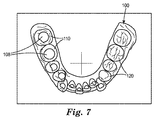
図7は、セグメント化プロセスの自動化された態様を示している。球面108のすべてが配置及び調整された時点で、使用者はコンピュータに歯のセグメント化手順を実行するように命令する。図の実施形態では、コンピュータアルゴリズムが歯列表面100の下顎歯列弓のそれぞれの歯110について実行され、下顎左第二大臼歯から始まり、下顎右第二大臼歯で終わる。他の歯の順序付けも可能であり、ツールバーにおいて使用される歯の番号付けの表記法に応じて、又は地域的慣行若しくは個々の使用者の好みに応じて適当である場合がある。
FIG. 7 shows an automated aspect of the segmentation process. Once all of the
好ましい一実施形態では、対応する球面108内に位置する歯列表面100のすべての表面三角形が部分的な歯の表面又は個々の歯の表面120の一部として指定される。歯の表面120が最初に画定された時点で、歯列表面100が、球面108から歯列表面110に沿って外側に延びる複数の経路に沿って分析されることによって歯の表面120と周辺構造とを分離する境界が自動的に認識される。それぞれの歯の表面120が完全に画定された時点で、対応する球面108が取り除かれ、図7に示されるように歯の表面120が色付け又は陰影付けされる。
In a preferred embodiment, all surface triangles of the
図8は、歯の表面120と周辺構造122とを分割する代表的な歯肉境界124をより詳細に示している。特定の一実施形態では、境界124は歯列表面110の表面に沿って凹面度をプロービングすることによって決定される。表面三角形が開始点としての歯の表面120の一部として既に指定された状態で、コンピュータアルゴリズムが、所定の数値特性を有する歯列表面110の表面三角形を外側に探索することによって進行する。この数値特性は、歯列表面100の局所的凹面度を決定するか又はその決定を助けうるものである。
FIG. 8 shows in greater detail an exemplary
アルゴリズムは、潜在的な境界三角形である表面三角形を探索するように進行する。潜在的な境界三角形は、歯と周辺構造との間の境界が見つかった可能性を示唆する条件である、凹面度の閾値を満たすものである。この閾値は、例えば、数値特性が閾値を上回るか、閾値を下回るか、又は所定の値の範囲にある場合に満たされうる。好ましい一実施形態では、数値特性は、所定の表面三角形の平面と、3個の可能な隣接する表面三角形の内の1つの平面との間に形成される角度である。また、数値特性は、表面三角形の内角、アスペクト比、又は全体の面積であってもよい。 The algorithm proceeds to search for surface triangles that are potential boundary triangles. A potential boundary triangle meets a concave degree threshold, which is a condition that suggests that a boundary between the tooth and the surrounding structure may have been found. This threshold value may be satisfied, for example, when the numerical characteristic is above the threshold value, below the threshold value, or within a predetermined value range. In a preferred embodiment, the numerical property is the angle formed between a plane of a given surface triangle and one of three possible adjacent surface triangles. The numerical characteristic may be an inner angle of the surface triangle, an aspect ratio, or an entire area.
上記の探索プロセスが繰り返し適用されることによって、それぞれの境界三角形が凹面度の閾値の要求条件を満たす、連続的な境界三角形がつながったチェーンが特定される。したがって特定された一連の三角形は、提案される歯肉境界を画定しうるものである。提案される歯肉境界は、例えば、それぞれの境界三角形が所定の閾値を満たす数値特性を有し、更に、この条件を同様に満たす隣接三角形を最大で2個有する場合に許容可能とみなされる。好ましい一実施形態では、数値特性は閾値が5°で始まる表面三角形の角度である。この条件を用いて、許容可能な歯肉境界(すなわち、歯肉縁)を与えるための表面三角形のセットを提案することができる。この条件が許容不能と判明した場合、閾値を0.5°刻みで小さくなるように繰り返し変化させ、このプロセスを許容可能な歯肉境界が与えられるまで繰り返す。 By repeatedly applying the above search process, a chain in which continuous boundary triangles are connected, each boundary triangle satisfying the requirement of the threshold value of concaveness, is identified. Thus, the identified series of triangles can define the proposed gingival boundary. The proposed gingival boundary is considered acceptable if, for example, each boundary triangle has a numerical characteristic that satisfies a predetermined threshold and further has a maximum of two adjacent triangles that also satisfy this condition. In a preferred embodiment, the numerical characteristic is the angle of the surface triangle starting with a threshold of 5 °. This condition can be used to propose a set of surface triangles to provide an acceptable gingival boundary (ie, gingival margin). If this condition turns out to be unacceptable, the threshold is repeatedly changed to decrease by 0.5 ° and the process is repeated until an acceptable gingival boundary is given.
更なる制約条件をソフトウェアにハードコード化してアルゴリズムの性能又はロバスト性を向上させることができる。例えば、歯の表面120の最大寸法を指定することができる。特定の実施形態では、歯の表面120のサイズは、12mm以下、14mm以下、15mm以下、16mm以下、又は18mm以下として指定される。必要に応じて、歯の表面120の最小寸法に制限を設けてもよい。
Additional constraints can be hard coded into the software to improve algorithm performance or robustness. For example, the maximum dimension of the
図8において、境界124は、特定された表面三角形のセットを結合するスプライン関数(立方スプライン関数など)を用いることによって滑らかにレンダリングされる。このように境界124が画定された後、歯の境界と交線との間の歯列表面の部分が第2の部分的な歯の表面として指定される。最後に、第1の部分的な歯の表面と第2の部分的な歯の表面とを合わせることによって完成された歯の表面120が形成される。
In FIG. 8, the
必要に応じて、また図に示されるように、境界124には、境界124に沿って配置された複数の調整可能なノード126が設けられている。ノード126は制御点として機能し、下記に述べるように使用者が境界124のエラーを修正することを可能とする。
As necessary and as shown, the
図9及び10は、使用者によって特定された境界124の欠陥を修正、すなわち「治す」ための従来のプロセスを示している。図に示されるように、使用者はポインターを使用して第1のノード130をクリックし、第2のノード132の方向にドラッグすることによって境界124に沿って閉じる必要のある隙間を示す。第1のノード130が第2のノード132に重ねて配置され、リリースされると、ソフトウェアがノード130、132間の境界124のエラーにより画定された部分を自動的に削除し、正しく補正された歯肉境界134が得られる。
FIGS. 9 and 10 illustrate a conventional process for correcting, or “cure”, the defect in the
図10は、ユーザインターフェースにおいて、歯の表面120を口腔の周辺表面から分離している歯肉境界136を示す、表面モデルのレンダリング上の視覚的標示を示している。この図に示されるように、境界136は歯の表面120を歯肉から、またお互いから分離している。歯肉境界136が条件を満たすものと判明した後、使用者は歯の表面120をそのまま許容する。図11及び12は、セグメント化された歯列表面138を示している。必要に応じて、また図に示されるように、境界136、ノード126、及び歯の陰影付けは、完成されたモデル138を分かりやすく示すために除かれている。
FIG. 10 shows a visual indication on the rendering of the surface model showing the
座標系の定義
歯列表面138が与えられた後、座標軸によって定義される座標系が、個別の歯の表面のそれぞれについて決定される。この工程は、図1Bのブロック56によって表される。
Coordinate System Definition After the
これらの座標軸を決定する1つの方法では、歯の表面上に1以上のランドマークを配置することを行う。例えば、図12及び13は、大臼歯表面142上の4個のランドマーク140の配置を示しており、それぞれのランドマークは大臼歯のそれぞれの咬頭の先端部に対応している。この例では、ランドマーク140の一は使用者により手動で選択される。使用者は、それぞれの歯の咬頭がよく見えるように歯の表面142に対して仮想カメラをパン、回転、又はズームすることができる。4個よりも多いか又は少ないランドマークを、与えられた歯の表面について定義することができる。特定の実施形態では、ソフトウェアは使用者に対して、歯列表面100に沿ってランドマーク140を順次配置することによってそれぞれの咬頭の位置を指定するように指示する。
One method of determining these coordinate axes involves placing one or more landmarks on the tooth surface. For example, FIGS. 12 and 13 show the arrangement of four
最初のランドマークの位置は、自動的又は半自動的に決定することもできる。例えば、コンピュータは、歯の表面142の全体的形状、歯の表面142の長軸、又は使用者によって指定される歯の表面142の他の特徴に基づいてランドマーク140の位置を提案することができる。必要に応じて、使用者はランドマーク140の配置を確認し、必要なだけ手動で調整を行うことができる。このプロセスは、咬頭を有する歯列表面100内の歯の表面142のすべてについて繰り返すことができる。これらには、大臼歯及び小臼歯が一般的に含まれる。
The position of the first landmark can also be determined automatically or semi-automatically. For example, the computer may suggest the location of the
ランドマーク140のすべてが歯の表面142上に配置された時点で、ランドマーク140は歯の表面142に対するそれぞれの座標系を定義するためにまとめて用いられる。例えば一実施形態では、大臼歯テーブル(大臼歯の咬合面に平行な基準面)が4個のランドマーク140に対する「最良適合」として最初に計算される。次に2個の頬唇側ランドマーク140が咬合面上に投射されることによって近心−遠心軸の位置及び方向が計算される。頬唇−舌軸も同様に大臼歯テーブル内に位置し、X軸に垂直な軸として計算される。最後に咬合−歯肉軸を他の2本の軸の外積から導出することができる。
Once all of the
必要に応じて、各ランドマークを歯の表面142の他の特徴に基づいて定義することもできる。例えば、歯の表面142の辺縁隆線/谷線を使用者が指定し、それぞれの歯の表面142について座標系を求める助けとすることもできる。図14Aは、歯の咬頭及び辺縁隆線の両方を対象とした最終的なランドマークを示す歯列表面100を示している。
If desired, each landmark can be defined based on other characteristics of the
図15〜17は、歯列表面100の歯について計算された座標系及び調整コントロールの3つの異なる図を示す。図に示されるように、第1の軸150(Z軸)は歯の表面152の認知される長軸に対して平行であり、第2の軸154は歯の切縁と同一直線上にあり、第3の軸156は軸150、154と交差し、頬唇側の歯の表面に対して実質的に垂直である。
FIGS. 15-17 show three different views of the coordinate system and adjustment controls calculated for the teeth on the
各座標軸は、6自由度で歯に対して便宜よく調整することができる。例えば各軸は、与えられた軸に沿った強調部分すなわち「チューブ」に適用される単純なクリック・アンド・ドラッグ動作によって並進させることができる。更に、各軸は、表示された軸の両端に見られる「ホイール」158を使用して容易に回転させることができる。ホイール158は、例えば、マウスのスクロールホイールを使用して作動させることができる。これにより、歯列表面110を方向付けする必要性を低減させる一方で、より容易かつ速やかなアラインメントが可能となることは有利な点である。
Each coordinate axis can be conveniently adjusted to the teeth with 6 degrees of freedom. For example, each axis can be translated by a simple click and drag action applied to an emphasis or “tube” along a given axis. In addition, each axis can be easily rotated using “wheels” 158 found at both ends of the displayed axis. The
ランドマーク140を使用することの代替手段として、「シングルクリック」法を用いて座標系を定義することができる。この方法では、仮想の歯上に所定の点を定義する点入力データを用い、仮想の歯に関連付けられた第1及び第2の軸を定義する軸入力データを受信し、前記点の周囲の歯の表面の一部分に対してほぼ法線となるベクトルを計算し、軸入力及び計算されたベクトルに基づいて歯の座標系を計算する。これは、頬唇側面が比較的小さなばらつきを示す切歯、犬歯、及び小臼歯について座標軸を決定するうえで特に有用である。図15〜17では、この実施形態が上顎右中歯の表面152について用いられている。座標系の生成は、下記に述べるように半自動的に行うことができる。
As an alternative to using the
図14Bは、3次元の表示環境における歯の表面の座標系を定義するための方向付けされたクロスヘアの使用を示している。この場合、垂直及び水平方向のクロスヘア151、153の位置は最初に使用者によって与えられ、垂直方向のクロスヘア151が歯の表面152の認知されるZ軸を反映している。水平方向のクロスヘア153と垂直方向のクロスヘア151との交点は、認知される歯の表面152の顔側軸(FA)点160などの認知される基準点を定義する。このユーザ入力は、歯の表面152上でカーソル制御装置を使用することで与えることができることは有利な点である。
FIG. 14B illustrates the use of oriented crosshairs to define the coordinate system of the tooth surface in a three-dimensional display environment. In this case, the position of the vertical and
必要な場合、クロスヘア150、154が直交しなくなるように水平方向のクロスヘア154を垂直方向のクロスヘア150に対して回転させることができる。この回転は、マウス上でスクロールホイール(又は他のポインティングデバイス)を動かしながら、キーボード上でコントロールキーを押さえるか、又は他の何らかの一時的なユーザ入力モードを入力することによって行うことができる。歯科矯正の処方との関連では、このような調整は、それぞれの歯の角度(又は「傾き」)の調整を表すうえで有用でありうる。有利な点として、このような調整は、患者の歯列の解剖学的構造に組み込まれた傾きを表すことが可能であり、これにより後で仮想歯群オブジェクトを所望の位置に向かって動かす際に適正な傾きを適用することができる。
If necessary, the
クロスヘア150、154及びFA点がこのようにして定義された状態で、FA点を位置の基準として用い、クロスヘアの少なくとも一方及び歯の表面の一部分に対する法線ベクトル(又は「法線」)を方向の基準として用いて座標系を計算することができる。これにより、コンピュータは、ユーザインターフェース上に、歯の座標系のX、Y及びZ軸を表す視覚的標示を与えることができる。
With the
一実施形態では、これは以下の方法を用いて実現することが可能である。 In one embodiment, this can be achieved using the following method.
a)矢状基準面Pが、垂直方向のクロスヘア150と表示面(図14Bのページの平面に等しい)との交線として定義される。平面Pは、図14Bに示される3D表示環境における垂直方向のクロスヘア150と仮想カメラの視点との交線を表す。次にこの平面Pと歯との間の交線が特定される(この結果はポリラインである)。このポリラインの最も咬合側の点を用いて歯の座標系の原点の位置が定義される。小臼歯については、この工程をわずかに変更したものが用いられる(すなわち、座標系の原点が頬唇側の咬頭のみを用いて定義されるように歯の舌側部分は除外される)。
b)クロスヘアオブジェクトの中心を中心として周囲に配置され、かつ表示面に垂直な、半径Rの円筒が形成される。代表的な一実施形態では、使用される半径は1mmである。
c)その円筒の内部で均一なポイントサンプリングを用いる(代表的な一実施形態では、この円筒状の領域の内部で約25個の点が使用される)。これらの点のそれぞれから歯の顔側面に向かって光線が延ばされる。歯の表面との交点を計算し、表面における法線を見つける。ポイントサンプリングからのすべての法線を平均化してFA点付近の歯の顔側面における平均法線を見つける。この工程では、局所的に粗い表面データによって生じうるすべてのスパイクを除去することができることは有利な点である。
d)上記工程c)で計算した平均法線を使用して座標系のY方向を定義する。
e)次に座標系の原点及び法線としてのY軸方向によって定義される平面上に垂直方向のクロスヘアを投射する。この投射の結果は、座標系のZ方向のベクトルである。
f)最後に、X方向のベクトルは単純に残りのベクトルである(z×y又はy×z)。
a) The sagittal reference plane P is defined as the intersection of the
b) A cylinder with a radius R, which is arranged around the center of the crosshair object and is perpendicular to the display surface, is formed. In one exemplary embodiment, the radius used is 1 mm.
c) Use uniform point sampling inside the cylinder (in a typical embodiment, about 25 points are used inside this cylindrical region). Rays extend from each of these points toward the face side of the tooth. Calculate the intersection with the tooth surface and find the normal on the surface. All normals from the point sampling are averaged to find the average normal on the face side of the tooth near the FA point. This process has the advantage that all spikes that can be caused by locally rough surface data can be removed.
d) Define the Y direction of the coordinate system using the average normal calculated in step c) above.
e) Next, a vertical crosshair is projected on the plane defined by the origin of the coordinate system and the Y-axis direction as the normal. The result of this projection is a vector in the Z direction of the coordinate system.
f) Finally, the vector in the X direction is simply the remaining vector (z × y or y × z).
他の変更例も可能である。例えば、FA点自体が座標系の原点を定義することができる。特定の実施形態では、上記工程(c)における点の配列は、表示面に対して平行な基準面内に位置し、仮想カメラの視点及び歯のFA点を通る線に沿って歯の上に投射される。特定の実施形態では、点の配列は、FA点において求められた法線ベクトルに沿って歯の上に投射される。点の配列は円筒状の領域から導出される必要はない。例えば、点の配列は、基準点の周囲の歯の部分を包囲する任意の幾何学的形状から導出することができる。上記の例のいずれにおいても、点の配列は、歯の表面を表すために用いられるそれぞれのポリゴン又は頂点に対する個々の法線ベクトルの平均である平均法線ベクトルに沿って歯の上に投射することができる。 Other variations are possible. For example, the FA point itself can define the origin of the coordinate system. In a specific embodiment, the array of points in step (c) above is located on a reference plane parallel to the display surface and on the tooth along a line passing through the virtual camera viewpoint and the FA point of the tooth. Projected. In certain embodiments, the array of points is projected onto the teeth along the normal vector determined at the FA points. The array of points need not be derived from a cylindrical region. For example, the array of points can be derived from any geometric shape that surrounds the portion of the tooth around the reference point. In any of the above examples, the array of points projects onto the teeth along an average normal vector that is the average of the individual normal vectors for each polygon or vertex used to represent the tooth surface. be able to.
図18は、すべての歯について座標系が定義された歯列表面100の上顎歯列弓を示している。更なる基準データとして、上記工程a〜cにおいて求めたそれぞれの歯の法線ベクトルがやはり図に示されている。有利な点として、この方法は、使用者が歯の構造の既知の欠陥を補正することを可能とするものである。1つの選択肢として、使用者が咬頭が摩耗していることを認識した場合、使用者は、その咬頭にランドマークを付けることを意図的に避けることにより、それぞれの歯について座標軸を設定する場合にこの欠陥の作用を避けることができる。また、このような欠陥は、上記に述べたような座標軸を手動で調整することによって修復することもできる。必要な場合、摩耗した咬頭のランドマークを「疑わしい」として特定し、注意を払いながらも更なる計算から除外することができる。
FIG. 18 shows an upper dental arch of the
このように座標系が定義されたなら、使用者は次に、座標系に関連付けられた1以上の仮想の歯に様々な改変を行うことができる。こうした改変には例えば、所定の歯軸に沿った、又はこれを中心とした歯の回転又は並進が含まれる。こうした改変には更に、歯への歯科矯正装置の取り付けが含まれる。好ましい一実施形態では、コンピュータは、こうした改変と整合するようにユーザインターフェースを更新する。 Once the coordinate system is defined in this way, the user can then make various modifications to one or more virtual teeth associated with the coordinate system. Such modifications include, for example, tooth rotation or translation along or about a predetermined tooth axis. Such modifications further include attaching orthodontic appliances to the teeth. In a preferred embodiment, the computer updates the user interface to be consistent with such modifications.
歯根株形成
座標系のすべてが定義された時点で、それぞれの歯の表面が閉多様体表面を与えるようにそれぞれの歯の表面に仮想的に人工歯根株を付加することができる。図1Bを再び参照すると、この工程はブロック58によって表されている。歯根株は、それぞれの歯の定義された座標系を反映し、使用者がそれぞれの歯の向きを隣の歯に対して視覚化する助けとなることから、歯科矯正のデジタルセットアップにおいて有用である。歯根株は治療計画を支援することもできる。例えば、歯根株は、治療の際に歯根間で生じうる干渉を予測するために歯科矯正医が使用することが可能な視覚化を与える。
Root root formation Once all of the coordinate systems have been defined, artificial root roots can be virtually added to each tooth surface such that each tooth surface provides a closed manifold surface. Referring back to FIG. 1B, this process is represented by
図19は、歯根株168の自動的な形成を示している。好ましい一実施形態では、歯根株168は、歯の表面の最終的な座標系及び人工歯根の予め定義された特徴的断面から計算される。予め定義された特徴的断面とは、モデル(又は理想化された)歯に由来し、モデル歯のZ軸に対して垂直な平面に沿った歯根の仮想的な「スライス」を表すものである。
FIG. 19 shows the automatic formation of the
以下の実施態様を用いて、走査された歯の表面に人工歯根を一体化することができる。 The following embodiments can be used to integrate an artificial tooth root into the surface of a scanned tooth.
1)それぞれの歯の表面に対してオブジェクト指向境界ボックスが定義される。
2)第2のより大きなオブジェクト指向境界ボックスが所定の歯根株の長さに基づいて歯の表面及び歯根株の両方について定義される。好ましくは所定の長さはハードコード化される。場合により、所定の長さはすべての歯根株について均一である。
3)次に、それぞれの歯の人工歯根の人工的断面が、方向付けされた境界ボックスのサイズに縮小される。
4)リアルスキャンされた点のポリゴンがそれぞれの人工的断面の平面内に生成される。
5)欠損した走査データの領域が、断面点を歯の表面によって変形させることによって与えられる。
6)リアルスキャンデータの領域上の水平スプラインが、リアルスキャンポリゴン及び変形された人工データに基づいて構築される。
7)リアススキャンデータ及び水平スプラインを考慮して垂直スプラインが定義される。
8)次にスキャンデータのない領域内に位置するスプラインが平滑化されて凹凸の強い領域が減らされる。この結果は、人工歯根株及び隣接歯間の歯の領域の表面を定義するスプライン点の3次元のグリッドである。
9)次にすべての人工部分のスプラインデータが三角形化される、すなわち3Dの三角形のメッシュに変換される。
10)最後に人工の縁部がリアルスキャンデータの縁部と接続されて歯根株が完全に一体化された歯の表面が生成される。
1) An object-oriented bounding box is defined for each tooth surface.
2) A second larger object-oriented bounding box is defined for both the tooth surface and root stock based on the length of the given root stock. Preferably, the predetermined length is hard coded. In some cases, the predetermined length is uniform for all root stocks.
3) Next, the artificial cross-section of each tooth artificial root is reduced to the size of the bounded bounding box.
4) Polygons of real scanned points are generated in the plane of each artificial cross section.
5) The missing scan data area is given by deforming the cross-sectional point by the tooth surface.
6) A horizontal spline on the real scan data area is constructed based on the real scan polygon and the deformed artificial data.
7) A vertical spline is defined taking into account the rear scan data and the horizontal spline.
8) Next, the spline located in the area where there is no scan data is smoothed to reduce the area with strong irregularities. The result is a three-dimensional grid of spline points that defines the surface of the tooth root area and the tooth area between adjacent teeth.
9) The spline data of all artificial parts is then triangulated, i.e. converted into a 3D triangular mesh.
10) Finally, the artificial edge is connected to the edge of the real scan data to produce a tooth surface with the root stock fully integrated.
図20は、一体化された歯要素の位置及び向きを操作するための調整コントロールの一環としての「チューブ」及び「ホイール」要素の使用を示している。この調整コントロールは、歯全体と関連付けられているため、歯の座標系に関連付けられたものとして上記に述べたものとは異なる。このため、この制御に対する調整により、歯がその座標軸とともに歯列弓に対して動く一方で、その座標軸は歯の幾何形状に対してその位置が保たれる。有利な点として、使用者は、歯科矯正の処方の極めて小さな変化に応じた歯の動きを可視化することが可能である。この図では、個々の歯の表面170のトルク及び角度におけるわずかな変化の影響が、歯列表面100内の周辺の歯に対して示されている。
FIG. 20 illustrates the use of “tube” and “wheel” elements as part of an adjustment control to manipulate the position and orientation of an integrated tooth element. Since this adjustment control is associated with the entire tooth, it differs from that described above as being associated with the tooth coordinate system. Thus, adjustments to this control move the tooth with respect to the dental arch along with its coordinate axis while maintaining its position relative to the tooth geometry. Advantageously, the user can visualize tooth movement in response to very small changes in orthodontic prescription. In this view, the effect of slight changes in the torque and angle of the
基準面の定義
歯根株が定位置に配された状態で、使用者は、この時点における歯列表面100の咬合面及び正中矢状面の一方又は両方を指定することができる(図1Bのブロック60)。咬合面は、歯の咬合部を通る仮想的な表面であり、平面によって概ね近似される。正中矢状面は、歯列弓の中央を長手方向に通り、歯列弓を左半分と右半分とに分割する仮想的な平面である。
Definition of Reference Surface With the root stock placed in a fixed position, the user can specify one or both of the occlusal surface and the mid-sagittal surface of the
図21は、歯列表面100上に咬合面172を導出するプロセスを示している。一実施形態では、コンピュータは、歯列表面100の個々の歯列弓に属する歯の表面の一部又はすべての形状若しくは座標系に基づいて咬合面172の初期近似を与える。例えば、咬合面172は、歯列表面100に重ね合わされた平面と接線方向に接する3個の点を特定することによって定義することができる。与えられた歯列弓について、これら3個の点は、左大臼歯からの少なくとも1個の接点、右大臼歯からの1個の接点、及び中央歯又は側歯からの1個の接点を一般的に含む。別の実施形態では、咬合面は、上記で定義したような歯の各座標系の各原点を表す各点に対する最良適合面として定義される。実際には、この平面は、歯の切縁、1個の咬頭先端部、又は頬側咬頭の先端部に概ね位置するこれらの原点の平均を表す。
FIG. 21 illustrates the process of deriving the
図22は、歯列表面100の正中矢状面174を導出した結果を示す。コンピュータは、歯列表面100の歯の表面の各座標系にしたがい、アーチフォームの形状に基づいてこの平面174を導出する。咬合面及び正中矢状面172、174の両方について、コンピュータは、使用者が適合するとみなされるように歯列表面100に対するそれらの位置及び/又は向きを手動で調整する選択肢を与える。
FIG. 22 shows the result of deriving the median
アーチフォームへの歯の配置
この時点で、歯列表面100は、歯根株が一体化された、別々の動くことができる一群の歯の表面を含んでいる。更に、咬合基準面及び正中基準面の両方が定義されている。この時点で、基本的な診断機能が利用可能である。例えば、使用者は、咬合面を重ね合わせることにより患者の歯列を対称性について調べることができる。次いで歯の表面の位置及び向きを調整して、図1Bのブロック61に表されるように上顎及び下顎のアーチフォームのそれぞれに歯の各表面を配置する。
Placement of teeth on the archform At this point, the
それぞれのアーチフォーム内の歯の各表面は、歯科矯正行為における公知の指針にしたがって配置される。例えば、これらの指針の一部のものは、自然の最適な歯列の歯の位置について述べたアンドリュー・ローレンス博士(Dr. Lawrence F. Andrew)による「Six Keys to Optimal Occlusion」に見ることができる。この情報は、「Straight Wire,The Concept and Appliance」(L.A.Wells,1989)という表題のアンドリュー博士の文献に記載されている。 Each tooth surface within each archform is placed according to known guidelines in orthodontic practice. For example, some of these guidelines can be found in “Six Keys to Optimal Occlusion” by Dr. Lawrence F. Andrew, who discusses the natural optimal dentition tooth position. . This information is described in Dr. Andrew's document entitled "Stright Wire, The Concept and Appliance" (LA Wells, 1989).
好ましくは、歯列表面100内の歯の各表面の配置は、1以上の定量的規則にしたがって行われる。一例として、規則によって、歯列弓内のすべての隙間を閉じることが求められる場合がある。好ましい一実施形態では、コンピュータアルゴリズムが、すべての歯の表面を所定のアーチフォームに規制しつつ、歯を歯列表面100の正中線の方向に押し詰めることによって歯の各表面間のすべての隙間を自動的に閉じる。使用者は、また、このような歯の押し詰め方法が、歯の表面が順次動かされるたびに自動的に行われるようにこの条件が維持されることを指定することもできる。
Preferably, the placement of each tooth surface within the
使用者は、歯の押し詰めプロセスに対する1以上の制約条件を指定することもできる。例えば、使用者は、1以上の歯の表面を「ピン留め」することを選択することにより、これらの歯の表面が歯列表面100に対して動かない一方で残りの歯が正中線の方向に押し詰められるようにすることができる。この制約条件は、1以上の歯の位置を動かすことを使用者が望まない場合に有利に適用することができる。
The user can also specify one or more constraints on the tooth compaction process. For example, the user may choose to “pin” one or more tooth surfaces so that the tooth surfaces do not move relative to the
発行米国特許第7,354,268号(ラビー(Raby)ら)に述べられるように、必要に応じて仮想アーチワイヤを定義することができ、1以上の歯の表面を仮想アーチワイヤに沿って特定の位置に動かすことができる。別の選択肢として、歯列表面100内の歯の各表面の位置を、発行米国特許第7,291,011号(ストーク(Stark))に述べられるように所定の歯科矯正の処方に基づいて決定することもできる。アーチフォームの定義は、上記の特許に述べられるような連続した円形の一連の円弧状セグメントで構成されたスプラインである必要はない。代わりに、アーチフォームは、連続した一連のパラメトリック3次曲線のセグメントで構成されたスプラインとして、又は他の何らかの連続的曲線の数学的定義にしたがって定義することもできる。
As described in issued US Pat. No. 7,354,268 (Raby et al.), A virtual archwire can be defined as desired, and one or more tooth surfaces can be routed along the virtual archwire. Can be moved to a specific position. As another option, the position of each tooth surface within the
1以上の歯を個別に調整することもできる。それぞれの歯の表面について調整することが可能な側面としては、トルク、傾き、1次回転、近心−遠心方向の動き(隣接歯間縮小(IPR)をともなうか又はともなわない)、咬合−歯肉方向の並進、及び頬唇−舌方向の並進が挙げられる。これらの側面のそれぞれは、それぞれの歯の表面の座標軸によって定義される6自由度の内の1つにおける運動に関連している。図15〜17で歯の表面152について上記に述べたように対応する調整を行うことができる。1以上の個別の歯に対する調整を用いて例えば所望のシュペー湾曲又はウィルソン湾曲を実施することができる。頬唇側又は舌側のブレースが治療を目的としている場合、1以上の歯の表面を特定のアーチワイヤ面に適合させるように調整を行うことができる。必要に応じて、これらの要求条件の1以上が歯科矯正医によって与えられる。
One or more teeth can also be adjusted individually. Sides that can be adjusted for each tooth surface include torque, tilt, primary rotation, mesial-distal movement (with or without adjacent interdental reduction (IPR)), occlusion-gingiva Directional translation and buccal lip-lingual translation. Each of these sides is associated with motion in one of six degrees of freedom defined by the coordinate axis of the respective tooth surface. Corresponding adjustments can be made as described above for the
図23は、協調的に調整された上顎基準歯列弓180及び上顎セットアップ歯列弓182上の複数の歯オブジェクトを示している。図に示されるように、使用者は、元の不正咬合を表す上顎基準歯列弓180の重ね合わされた像を見ながらアーチフォームの調整を行うことができ、上顎セットアップ歯列弓182は、元のアーチフォームの基本的形状をできるだけ保存するように調整される。アーチフォームの形状は、ノード184をクリックし、それぞれの歯列弓の形状を定義するスプライン186上にドラッグすることによって調整される。使用者は、スプライン186上に更なるノード又は制御ポイントを生成することによってアーチフォームの形状をより正確に調整することもできる。
FIG. 23 shows a plurality of tooth objects on the upper reference
歯列弓の長さ、犬歯間の幅、大臼歯間の幅、前歯の唇側傾斜を含む歯科矯正医によって指定される任意の数の定量的要求条件を満たすように上記に述べたような歯列表面100内の歯の各表面の操作を行うことができる。しかしながら、同時に、患者の生理的条件を考慮すると可能な歯の動きの種類には制約がある。すべての要求条件を満たすことが不可能な場合には、使用者は歯科矯正医と連絡を取って要求条件の内の1以上を緩和して許容可能な妥協点を決定することができる。
As stated above to meet any number of quantitative requirements specified by the orthodontist, including the length of the dental arch, the width between the canines, the width between the molars, the labial inclination of the anterior teeth Manipulation of each tooth surface within the
2本の歯が衝突する場合には、コンピュータがこのような衝突に対して応答する異なる方法がある。1つの種類の応答では、衝突する歯の表面同士は互いに交差させられる。必要に応じて、また図24に示されるように、衝突している歯の表面を「フラグ付け」する(例えば、表示されるように歯の表面183を色付けすることによる)ことによって2個の歯の表面間で交差が生じたことを示すことができる。第2の種類の応答では、衝突する歯の表面が単純に停止することにより、交差が生じることが防止される。第3の種類の応答では、衝突する歯が他方の歯と交差することが防止される一方で、衝突の性質に基づいて限定された歯の動きが可能である。例えば、歯の手動又は入力による動きはいずれも、1以上の隣接歯との接触が生じるまで、異なる軸に沿って、又は軸の周囲にその歯を強制的に動かす自動的な運動をともないうる。必要に応じて、コンピュータは、使用者が1以上の歯の表面の位置及び向きを調整する際に好ましい応答の種類を選択する選択肢を与える。
When two teeth collide, there are different ways in which the computer responds to such a collision. In one type of response, the impinging tooth surfaces intersect each other. If necessary, and as shown in FIG. 24, two flags can be created by “flagging” the impinging tooth surface (eg, by coloring the
上記に述べた第3の種類の衝突は、2個の歯の表面が衝突する際に生じる物理的及び生理学応答をシミュレートすることができるために特に有利となりうる。2個の歯の表面が直接干渉することを防止することが可能であるが、第1の歯の表面に対するシミュレートされた力(例えば、重力又は咬合力)の作用に基づいて第1の歯の表面の方向を逸らせて、第2の歯の表面を過ぎて滑らせることも可能である。別の言い方をすれば、第1及び第2の仮想の歯が衝突する場合であっても、入力データを許容可能な第1の歯の運動に向けることができる。しかしながら、衝突の結果、第1の歯の運動は、シミュレートされた力の作用に関連付けられた所定の方向に沿って、又はその方向の周囲に制限もされうる。これらの原理の一部は、下記及び図25〜41に述べられるアルゴリズムにおいて機能する。 The third type of collision described above can be particularly advantageous because it can simulate the physical and physiological responses that occur when two tooth surfaces collide. Although it is possible to prevent the two tooth surfaces from interfering directly, the first tooth is based on the effect of a simulated force (eg gravity or occlusal force) on the first tooth surface. It is also possible to deflect the surface of the second tooth and slide past the surface of the second tooth. In other words, even if the first and second virtual teeth collide, the input data can be directed to an acceptable first tooth movement. However, as a result of the collision, the movement of the first tooth may also be limited along or around a predetermined direction associated with the simulated force action. Some of these principles work in the algorithm described below and in FIGS.
加えられた力に基づいた衝突の検出
図25は、対象とする特定の歯の表面(すなわち、選択された歯)を他の歯の表面に対して動かす際に生じる歯と歯の衝突を検出し、それに応答するためのアルゴリズムの全体的フローチャートを示している。本明細書において使用するところの「歯」及び「歯の表面」なる用語は互換可能に用いられる。衝突の検出の目的では、歯には、天然歯冠、天然歯根、人工歯冠、ベニア、インレー、アンレー、インプラント、ブリッジ、部分義歯、又は歯に取り付けられる装置の少なくとも一部が含まれうる。更に、「交差」と「衝突」なる用語は互換可能に用いられる。このアルゴリズムは、歯列弓内における衝突及び対向する歯列弓間の衝突に適用することができる。このフローチャートにおいて下線を付した文は、別のフローチャートにおいて与えられ、本明細書の別の箇所に述べられる別の関数についての言及を示す。
Detection of Collisions Based on Applied Forces FIG. 25 detects tooth-to-tooth collisions that occur when moving a particular tooth surface of interest (ie, a selected tooth) relative to other tooth surfaces. And shows an overall flowchart of the algorithm for responding to it. As used herein, the terms “tooth” and “tooth surface” are used interchangeably. For the purposes of collision detection, teeth can include natural crowns, natural roots, artificial crowns, veneers, inlays, onlays, implants, bridges, partial dentures, or at least some of the devices attached to the teeth. Furthermore, the terms “intersection” and “collision” are used interchangeably. This algorithm can be applied to collisions within the dental arch and collisions between opposing dental arches. The underlined text in this flow chart is given in another flow chart and indicates a reference to another function described elsewhere in this specification.
最初に、ブロック200に示されるように、コンピュータがどの隣接歯が選択された歯と衝突しうるかを決定する。一般的に、これらの歯には、選択された歯の近心側及び遠心側の隣接歯、並びに反対の歯列弓上のあらゆる対向する歯が含まれる。ある歯は、最大で1本の近心側の隣接歯及び最大で1本の遠心側の隣接歯を一般的に有するが、反対側の歯列弓上に位置する2本以上の対合歯(すなわち対向歯)を有しうる。
Initially, as shown in
ブロック202では、コンピュータは6つの軸(すなわち3つの並進軸と3つの回転軸)の内のどれが加えられる力と関連付けられるかを選択する。ブロック204に進むと、コンピュータは、それに沿って、又はそれを中心として選択された軸が力の作用を表す正又は負の方向を選択する。例えば、近心方向を正の方向として、遠心方向を負の方向として、咬合方向を正の方向として、歯肉方向を負の方向として、といったように定義することができる。正及び負の方向について用いられる基準は、歯科矯正装置の処方又は仕様において一般的に用いられているものに準ずることが好ましい。
In
次に、ブロック206において、選択された力の軸以外の軸の内の1以上を調整することができる。これは、適当なユーザインターフェースを用いて使用者が行うことができる。例えば、これらの調整は、3D歯列表面に取り付けられた歯調整コントロールからの入力、又は歯特性パネルのスライダーであってもよい。選択された歯は、手動で調節される軸に沿って又はこの軸を中心として小刻みに動くことが好ましい。
Next, at
次にブロック208を参照すると、隣接歯と1個の接点が得られるまで選択された軸に沿って、又はこの軸を中心として選択された方向に力を加えるための関数が実行される。別の言い方をすれば、選択された歯が力の方向の隣接歯と交差している場合、選択された歯は交差がなくなるまで最初に逆方向に動かされる。 Referring now to block 208, a function is executed to apply a force along or about a selected axis until a contact with an adjacent tooth is obtained. In other words, if a selected tooth intersects an adjacent tooth in the direction of force, the selected tooth is first moved in the opposite direction until there is no intersection.
ブロック210では、使用者は次にソフトウェアのセットアップモードから出るか、又は選択を変える選択肢を有する。いずれかの条件が成り立つ場合にはプロセスはブロック206に戻り、そうでない場合にはプロセスは終了する。
At
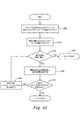
軸に沿って/軸を中心とした力を加える。
図26は、ブロック208によって表されるような、軸に沿った、又は軸を中心とした力を加える関数をより詳細に示すフローチャートを示している。先ず、ブロック212、214に示されるように、適当な並進又は回転の増分が最初に与えられる。この実施形態では、並進又は回転の増分は関数パラメータとして与えられる。
Apply force along / about the axis.
FIG. 26 shows a flowchart illustrating in more detail the function of applying a force along or about an axis, as represented by
ブロック216に進むと、コンピュータは、選択された歯がいずれかの隣接(近心側/遠心側/対合)歯と衝突しているか否かを判定する。この場合、考慮される隣接歯はブロック200において上記で選択されたものである。選択された歯が隣接歯と衝突している場合にはブール変数、「initiallyInCollision」(初期に衝突状態)が「true」に設定され、選択された歯がいずれの隣接歯とも衝突していない場合には「false」に設定される。
Proceeding to block 216, the computer determines whether the selected tooth collides with any adjacent (mesial / distal / paired) tooth. In this case, the adjacent teeth considered are those selected above in
ブロック218では、繰り返しカウンターが0に設定され、最大の繰り返し数「maxIterations」が所定の量(例えば、20)に設定される。次に、ワークフローはブロック220、222、224のうちの1以上へと続く。ブロック220、222、224のそれぞれは、ブロック202において選択された力の軸が3つの並進軸(近心−遠心方向、頬唇−舌方向、又は咬合−歯肉方向)の内の1つに対応するか否かを判定する。この条件が満たされた場合、コンピュータは、ブロック226、228、230によって表される別々の関数を実行して、加えられる力に応じて近心−遠心方向、頬唇−舌方向、又は咬合−歯肉方向のそれぞれへの並進を決定する。
At
選択された力の軸が3つの並進軸のいずれにも対応していない場合、ワークフローは図27に示されるフローチャートに進む。ブロック232、234、236によって示されるように、コンピュータは、選択された軸が3つの回転軸(1次回転、傾きの回転、又はトルク回転)の1つであるか否かを判定する。これらの回転軸のいずれかが当てはまる場合、ブロック238、240、242のいずれかにしたがって適当な1次回転、傾きの回転、又はトルク回転が決定される。
If the selected force axis does not correspond to any of the three translation axes, the workflow proceeds to the flowchart shown in FIG. As indicated by
ブロック244に示されるように、次に選択された歯が、最も新しい並進及び回転の設定を用いてアーチフォーム上に再配置される。この時点で歯は、ブロック226、228、230、238、240、242において決定される並進又は回転に基づいて微調整された位置又は向きを有しているはずである。ブロック246に移行すると、繰り返しカウントは1だけ増える。次にブロック248において、コンピュータは選択された歯がその隣接歯のいずれかと衝突状態にあるか否かを判定する。衝突状態にある場合、ブール変数「inCollision」(衝突状態)が「true」に設定され、そうでない場合には「false」に設定される。
As shown in
ブロック250は繰り返しにおける最後の工程を示し、ここでコンピュータが、ブール変数「initiallyInCollision」と「inCollision」とが同じであるか否か、かつ繰り返しの最大数に達しているか否かを判定する。これらの条件の両方が満たされている場合、ワークフローはブロック220に戻り、上記に述べたようにプロセスが再び繰り返される。両方の条件が満たされていない場合、プロセスは図28のフローチャートのブロック252へと続く。
ブロック252は、図26、27において上記に述べた繰り返しループを出るための理由を決定する。「inCollision」の値が妥当な繰り返し数の範囲内で変化しなかった場合、プロセスはブロック254に進み、ここで回転/並進に対するすべての変化が取り消される。別の言い方をすると、ブロック254では、選択された力の軸に応じて、「DistanceFromMidline」(正中線からの距離)、「TranslationNormalToArchform」(アーチフォームに垂直な並進)、「Eminence」(隆起)、「FirstOrderRotation」(一次回転)、「Tip」(傾き)、又は「Torque」(トルク)のそれぞれの初期値への復帰が起こる(図25を参照)。
これに対して、「inCollision」の値が妥当な繰り返し数の範囲内で変化した場合(「MaxIteration」よりも少ない回数)、プロセスはブロック256へと続く。ブロック256は、「initiallyInCollision」の値に基づいて歯が初期に衝突状態にあるか否かを判定する。
In contrast, if the value of “inCollision” changes within a reasonable number of iterations (number of times less than “MaxIteration”), the process continues to block 256.
「initiallyInCollision」が「TRUE」である場合、歯はすぐ前の並進又は回転を取り消す(ブロック258に記載)ことによって衝突状態から外されるか、又は選択された力の軸に応じて「DistanceFromMidline」、「TranslationNormalToArchform」、「Eminence」、「FirstOrderRotation」、「Tip」、又は「Torque」のそれぞれの前の値への復帰が起こる(図25より)。次にブロック260を参照すると、次に歯は現在の位置及び向きの設定でアーチフォーム上に再配置され、プロセスはブロック262に移行する。 If “initiallyInCollision” is “TRUE”, the tooth is removed from the collision state by canceling the previous translation or rotation (described in block 258), or “DistanceFromMidline” depending on the axis of force selected. , “TranslationNormalToArchform”, “Eminence”, “FirstOrderRotation”, “Tip”, or “Torque” is restored to the previous value (from FIG. 25). Referring now to block 260, the teeth are then repositioned on the archform with the current position and orientation settings, and the process moves to block 262.
「initiallyInCollision」が「FALSE」である場合、位置又は向きに対する調整は不要であり、プロセスはブロック262に直接移行する。 If “initiallyInCollision” is “FALSE”, no adjustment to position or orientation is required and the process moves directly to block 262.
ブロック262において、歯は隣接歯と交差しなくなるように動かされる。これについては、後の項でより詳しく述べる。
At
並進/回転の決定
この項では、選択された歯の6自由度に基づいて3つの可能な並進及び3つの可能な回転のそれぞれを決定するために用いられる6つの別々のフローチャート(図29〜34)について述べる。
Translation / Rotation Determination In this section, six separate flowcharts (FIGS. 29-34) used to determine each of the three possible translations and three possible rotations based on the six degrees of freedom of the selected tooth. )
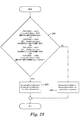
図29は、近心−遠心軸に沿った並進を決定するプロセスを示している。ブロック264は、力の方向、選択された歯が衝突状態にあるか否か、及び選択された歯が位置する象限の3つの因子の組み合わせに基づいて運動の方向を設定する。例えば、選択された歯が衝突状態にある場合、方向は、歯を衝突から遠ざかる方向に動かすように設定される。別の例として、正の近心−遠心の力の方向は、左から右の象限(又はその逆)に横切る場合に、これらの力の座標系の原点を横断するために逆転する。
FIG. 29 illustrates the process of determining translation along the mesial-distal axis.
正又は負の並進のいずれが必要とされるかに基づいて、プロセスはブロック266又はブロック268に進み、「DistanceFrom Midline」をそれぞれ漸増又は漸減させる。この場合、増分又は減分の大きさは、図26のブロック212によって予め定義される。
Based on whether positive or negative translation is required, the process proceeds to block 266 or block 268 and increments or decrements “DistanceFrom Midline”, respectively. In this case, the magnitude of the increment or decrement is predefined by
図30は、頬唇−舌軸に沿った並進を決定するプロセスを示している。この場合、ブロック270は、運動の方向、及び選択された歯が衝突状態にあるか否かの2つのみの因子によって決定される運動の方向を設定する。正又は負の並進のいずれが必要とされるかに応じて、プロセスはブロック272又はブロック274に進み、「TranslationNormalToArchform」をそれぞれ漸増又は漸減させる。「TranslationNormalToArchform」に対する増分又は減分の大きさは、図26のブロック212によって予め定義される。
FIG. 30 illustrates the process of determining translation along the buccal lip-lingual axis. In this case, block 270 sets the direction of motion as determined by only two factors: the direction of motion and whether the selected tooth is in a collision state. Depending on whether positive or negative translation is required, the process proceeds to block 272 or block 274, where “TranslationNormalToArchform” is incremented or decremented respectively. The magnitude of the increment or decrement for “TranslationNormalToArchform” is predefined by
図31は、咬合−歯肉軸に沿った並進を決定するプロセスを示している。ブロック276は、力の方向、及び選択された歯が衝突状態にあるか否かによって決定される運動の方向を設定する。正又は負の並進のいずれが必要とされるかに応じて、プロセスはブロック278又は280に進んで「Eminence」をそれぞれ漸増又は漸減させる。「Eminence」に対する増分又は減分の大きさは、図26のブロック212によって予め定義される。
FIG. 31 illustrates the process of determining translation along the occlusal-gingival axis.
図32は、咬合−歯肉軸(又は歯の長手方向軸)に沿った一次回転を決定するプロセスを示している。ブロック282は、力の方向、及び選択された歯が衝突状態にあるか否かによって決定される運動の方向を設定する。正又は負の並進のいずれが必要とされるかに応じて、プロセスはブロック284又は286に進んで「FirstOrderRotation」をそれぞれ漸増又は漸減させる。「FirstOrderRotation」に対する増分又は減分の大きさは、図26のブロック214によって予め定義される。
FIG. 32 illustrates the process of determining the primary rotation along the occlusal-gingival axis (or the longitudinal axis of the tooth).
図33は、頬唇−舌軸に沿った傾きの回転を決定するプロセスを示している。ブロック288は、力の方向、及び選択された歯が衝突状態にあるか否かによって決定される運動の方向を設定する。正又は負の並進のいずれが必要とされるかに応じて、プロセスはブロック290又は292に進んで「Tip」をそれぞれ漸増又は漸減させる。「Tip」に対する増分又は減分の大きさは、図26のブロック214によって予め定義される。
FIG. 33 illustrates the process of determining tilt rotation along the buccal lip-lingual axis.
図34は、近心−遠心軸を中心としたトルク回転を決定するプロセスを示している。ブロック294は、力の方向、及び選択された歯が衝突状態にあるか否かによって決定される運動の方向を設定する。正又は負の並進のいずれが必要とされるかに応じて、プロセスはブロック296又は298に進んで「Torque」をそれぞれ漸増又は漸減させる。「Torque」に対する増分又は減分の大きさは、図26のブロック214によって予め定義される。
FIG. 34 illustrates the process of determining torque rotation about the mesial-centrifugal axis.
選択された歯が衝突状態にあるか否かの決定
図35〜36は、選択された歯が隣接歯と衝突状態にあるか否かを判定するための代表的なプロセスを説明するフローチャートである。図35では、ブロック300により示されるように衝突の種類が最初に指定される。この例では、この入力は、「CheckMesialNeighbor」(近心側隣接歯の確認)、「CheckDistalNeighbor」(遠心側隣接歯の確認)、及び「CheckAntagonists」(対合歯の確認)の3つの可能な値から選択される関数パラメータとして与えられる。
Determining Whether Selected Teeth are in Collision FIGS. 35-36 are flowcharts illustrating an exemplary process for determining whether a selected tooth is in collision with an adjacent tooth. . In FIG. 35, the type of collision is first designated as indicated by
ブロック302は、選択された歯とその近心側の隣接歯との間に衝突があるか否かを判定するためのテストを表している。必要に応じて、またブロック302に示されるように、このような衝突は、選択された歯が最も近心側の歯ではなく、その近心側の隣接歯と交差するか、又は選択された歯が最も近心側の歯であり、反対側の象限(左に対する右、及びその逆)の最も近心側の歯と交差する場合にこのような衝突が存在する。
この条件が満たされない場合、プロセスは図36のフローチャートへと続く。 If this condition is not met, the process continues to the flowchart of FIG.
この条件が満たされる場合、プロセスはブロック304に進み、ここで選択された歯がその対応する象限における最も近心側であるかが問い合わされる。そうでない場合には、選択された歯の近心側の隣接歯はブロック306において選択された歯と衝突状態にあるものとして記録される。別の言い方をすれば、選択された歯は「inCollisionWithTeeth」(歯との衝突あり)リストに追加される。次にプロセスは図36のフローチャートに進む。選択された歯がその象限における最も近心側である場合、プロセスはブロック308に進み、ここで選択された歯の象限が決定される。この決定に基づき、左最近心歯(ブロック310)又は右最近心歯(ブロック312)が「inCollisionWithTeeth」リストに追加される。
If this condition is met, the process proceeds to block 304 where it is queried whether the selected tooth is the most mesial in its corresponding quadrant. Otherwise, the mesial adjacent tooth of the selected tooth is recorded as being in collision with the selected tooth at
図36において、プロセスはブロック314へと続き、適用可能な場合には遠心側の隣接歯との衝突について確認される。選択された歯と遠心側の隣接歯との間の交差が検出された場合には遠心側の隣接歯は「inCollisionWithTeeth」リストに追加される(ブロック316)。いずれの場合も、プロセスはブロック318に移行し、ここで選択された歯と交差する対合歯があるか否かを判定するための別の関数が実行される。 In FIG. 36, the process continues to block 314 where it is checked for collisions with the distal adjacent teeth if applicable. If an intersection between the selected tooth and the distal adjacent tooth is detected, the distal adjacent tooth is added to the “inCollectionWithTeeth” list (block 316). In either case, the process moves to block 318 where another function is performed to determine if there is a matching tooth that intersects the selected tooth.
ブロック320に移行すると、選択された歯が1以上の対合歯と交差すると判定され、「CheckAntagonists」(対合歯を確認)が選択されると、すべての交差する対合歯が「inCollisionWithTeeth」リスト(ブロック322)に追加される。図36に示されるように、ブロック320において条件が満たされるか否かとは無関係にプロセスはブロック324に進む。ブロック324は、「inCollisionWithTeeth」リストが歯を含んでいるか否かを判定する。yesである場合、関数は値「TRUE」を返し、そうでなければ関数は値「FALSE」を返す。
Moving to block 320, it is determined that the selected tooth intersects with one or more counter teeth, and if “Check Antagonists” is selected, all intersecting counter teeth are “in Collision With Teeth”. It is added to the list (block 322). As shown in FIG. 36, the process proceeds to block 324 regardless of whether the condition is met at block 320.
選択された歯と交差する対合歯の決定
図37のフローチャートは、選択された歯と対合歯が交差するか否かを判定する関数を与えるものである。ブロック326は、選択された歯が上顎歯列弓又は下顎歯列弓のいずれにあるかを判定する。次に、選択された歯を含む歯列弓と対向する歯列弓のすべての歯を含むように「OpposingArchTeeth」が定義される(ブロック328、330)。ブロック332に進むと、現在の歯が「OpposingArchTeeth」のリストの1番目の歯として設定される。次いで繰り返しプロセスが実行される。ブロック334は、現在の歯が実際の歯であり、ナル値ではないか否かを問い合わせる。現在の歯が実際の歯であると仮定すると、ブロック336は選択された歯が現在の歯と交差するか否かを判定する。交差する場合、現在の歯は対合歯のリストに追加される(ブロック338)。いずれの場合も、プロセスはブロック340に続き、現在の歯が「OpposingArchTeeth」のリストの次の歯に設定される。ここから、プロセスは、「OpposingArchTeeth」により列挙されたすべての歯がテストされるまで図37に示されるようにブロック334から始まるプロセスを繰り返す。
Determination of a pair of teeth that intersect with a selected tooth The flowchart of FIG. 37 provides a function that determines whether a selected tooth and a pair of teeth intersect.
最後に、ブロック342が、対合歯が見つかったか否かを判定する。対合歯が見つかった場合、関数は値「TRUE」を返し(ブロック345)、そうでない場合には関数は値「FALSE」を返す(ブロック343)。 Finally, block 342 determines whether a counter tooth has been found. If a pair of teeth is found, the function returns the value “TRUE” (block 345), otherwise the function returns the value “FALSE” (block 343).
選択された歯を隣接歯と衝突しなくなるように移動
選択された歯を隣接歯と衝突しなくなるように動かすために用いられる代表的なプロセスを、図38〜41に示される4つの部分からなるフローチャートで説明する。始めに、ブロック344が、衝突がなくなると考えられる点を決定するための交差値を決定する。この例では、交差値は関数パラメータであり、選択された歯と隣接歯との間の接触が、両者の間の最も接近した距離がこの交差の範囲内となる場合に満たされるように定義される。
Move the selected tooth so that it no longer collides with the adjacent tooth. The typical process used to move the selected tooth so that it no longer collides with the adjacent tooth consists of the four parts shown in FIGS. This will be described with reference to a flowchart. Initially, block 344 determines the intersection value to determine the point at which the collision is considered to be eliminated. In this example, the intersection value is a function parameter and is defined such that the contact between the selected tooth and the adjacent tooth is satisfied if the closest distance between them is within the range of this intersection. The
ブロック346では、異なる変数が初期化される。示される例では、乗算器はナル値に設定され、「currentlyInCollision」(現在、衝突状態)が「TRUE」に設定され、「inCollisionWithTeeth」(歯と衝突状態)がナル値に設定される。
At
ブロック348は、選択された歯と隣接歯との間の接触が交差の範囲内で実現されるまで繰り返すループの開始点を示す。次いで下記に述べる8種類の運動のそれぞれに基づいて運動がプローブされる。
ブロック348は、選択された歯のすぐ前の運動が「DistanceFromMidline」を変化させたか否かを判定する。変化させた場合、ブロック350が実行され、与えられた歯の特性について適切な運動の増分が計算される。この場合、例えば、運動の増分は、「DistanceFromMidline」(正中線からの距離)及び「PreviousDistanceFromMidline」(前の正中線からの距離)の2つの変数に基づいて計算することができる。図に示されるように、次にプロセスはブロック352に続く。
ブロック352は、選択された歯のすぐ前の運動が、「TranslationTangentToArchform」(アーチフォームの接線方向への並進)を変化させたか否かを判定する。変化させた場合、ブロック354が実行され、「TranslationTangentToArchform」及び「PreviousTranslationTangentToArchform」に基づいて計算された対応する運動の増分が計算される。図に示されるように、次にプロセスはブロック356に続く。
ブロック356は、選択された歯のすぐ前の運動が、「TranslationNormalToArchform」(アーチフォームの法線方向への並進)を変化させたか否かを判定する。変化させた場合、ブロック358が実行され、「TranslationNormalToArchform」及び「PreviousTranslationNormalToArchform」に基づいて計算された対応する運動の増分が計算される。図に示されるように、次にプロセスは図39のブロック360に続く。
ブロック360は、選択された歯のすぐ前の運動が、「Eminence」(隆起)を変化させたか否かを判定する。変化させた場合、ブロック362が実行され、「Eminence」及び「PreviousEminence」(前の隆起)に基づいて計算された対応する運動の増分が計算される。図に示されるように、次にプロセスはブロック364に続く。
ブロック364は、選択された歯のすぐ前の運動が、「FirstOrderRotation」(一次回転)を変化させたか否かを判定する。変化させた場合、ブロック366が実行され、「FirstOrderRotation」及び「PreviousFirstOrderRotation」(前の一次回転)に基づいて計算された対応する運動の増分が計算される。図に示されるように、次にプロセスはブロック368に続く。
ブロック368は、選択された歯のすぐ前の運動が、「Tip」(傾き)を変化させたか否かを判定する。変化させた場合、ブロック370が実行され、「Tip」及び「PreviousTip」(前の傾き)に基づいて計算された対応する運動の増分が計算される。図に示されるように、次にプロセスはブロック372に続く。
ブロック372は、選択された歯のすぐ前の運動が、「Torque」(トルク)を変化させたか否かを判定する。変化させた場合、ブロック374が実行され、「Torque」及び「PreviousTorque」(前のトルク)に基づいて計算された対応する運動の増分が計算される。図に示されるように、次にプロセスはブロック376に続く。
ブロック376は、選択された歯のすぐ前の運動が、「OpposingArchContactOffset」(対向歯列弓との接触オフセット)を変化させたか否かを判定する。変化させた場合、ブロック378が実行され、「OpposingArchContactOffset」及び「PreviousOpposingArchContactOffset」(前の対向歯列弓との接触オフセット)に基づいて計算された対応する運動の増分が計算される。図に示されるように、次にプロセスは図40のブロック388に続く。
ブロック388では、選択された歯をアーチフォーム上に仮想的に配置するための関数が実行される。ブロック390に移行すると、次にコンピュータは、選択された歯が隣接歯と衝突状態にあるか否かを判定するためのプロセスを実行する。次のブロック392は、選択された歯の衝突状態に変化があるか否かを判定する(すなわち、currentlyInCollision=InCollisionか?)。変化がある場合、乗算器及び「currentlyInCollision」の両方が無効化される(ブロック394)。
At
最後に、ブロック396が、運動の絶対値が交差よりも大きいか否か、又は選択された歯が依然として衝突状態にあるか否かを判定する。運動の絶対値が交差よりも大きいか、又は選択された歯が衝突状態にある場合、プロセスは図38におけるブロック348から再び繰り返される。そうでない場合には、関数は終了する。
Finally, block 396 determines whether the absolute value of the motion is greater than the intersection or whether the selected tooth is still in a collision state. If the absolute value of movement is greater than the intersection or the selected tooth is in a collision state, the process is repeated again from
所定の歯の特性に対する運動の増分の計算
図41は、選択された歯を衝突しなくなるように動かすために用いられる運動の増分を決定する関数に関するものである。この関数は、選択された歯が、衝突はしなくなるが隣接歯と「接触状態」に維持される位置に効率的に向かうように、図38〜40のループの各繰り返しにおいて運動の増分を調整する。
Calculation of motion increments for a given tooth characteristic FIG. 41 relates to a function that determines the motion increments used to move selected teeth out of collision. This function adjusts the increment of motion in each iteration of the loop of FIGS. 38-40 so that the selected tooth is effectively headed to a position where it will not collide but remain “in contact” with the adjacent tooth. To do.
このプロセスはブロック404及び406で始まり、ここで、「currMovementPropValue」(現在の運動適正値)及び「prevMovementPropValue」(前の運動適正値)に関する入力がそれぞれ与えられる。これらは、対象とする運動に対する選択された歯の現在及び前の位置を表す関数パラメータである。
The process begins at
乗算器が宣言されていない(すなわち乗算器がナル値である)場合(ブロック408)、プロセスは直接ブロック416に進む。しかしながら、乗算器がナル値である場合には、プロセスはこの変数を定義するためのブロック410に進む。ブロック410は、「currMovementPropValue」が「prevMovementPropValue」より小さいか否かを判定する。「currMovementPropValue」が「prevMovementPropValue」より小さい場合、運動の方向が反転するように乗算器は−1に設定される(ブロック412)。そうでない場合には乗算器は1に設定される(ブロック414)。
If the multiplier has not been declared (ie, the multiplier is a null value) (block 408), the process proceeds directly to block 416. However, if the multiplier is a null value, the process proceeds to block 410 for defining this variable.
ブロック416は、((currMovementPropVal−PrevMovementPropVal)/2)の絶対値として「movementAmount」を定義し、ブロック418は、「currMovementPropVal」を乗算器×movementAmountだけ漸増させる。次に、ブロック420では、「LastChangedMovementPropVal」(すぐ前に変更された運動適正値)は「currMovementPropVal」に設定され、これにより歯の持続的な特性が定義される。最後に、この関数はブロック422で終了し、「currMovementPropVal」の新しい値が返される。
咬合の設定
使用者は、図1Bのブロック62によって表されるように、所望の咬合にしたがって歯列表面100の歯の各表面に調整を行うことによって進む。対向する歯列弓の歯群間の相互作用は、同じ歯列弓の歯群間の相互作用と同様に処置することができる。「アーチフォームへの歯の配置」について上記に述べた基本的な器具及び手順の多くは同様に用いられるため、これらをここで再び検討することはしない。
Occlusion Setting The user proceeds by making adjustments to each tooth surface of the
一般的に、上顎歯列弓と下顎歯列弓との間の咬合の設定は、歯の適正な咬頭嵌合を定義することでしばしば始まる。例えば、歯科矯正医は、下顎第一大臼歯の頬側溝が上顎第一大臼歯の近心頬側咬頭と咬合する、I級の大臼歯の関係を必要とする場合がある。歯群が適正な大臼歯の関係に案内されうるか否かは、アーチフォーム、上顎及び下顎歯列弓の長さの間の関係、個々の歯の座標系(すなわちそれぞれの歯の位置及び向き)、並びに歯の大きさ及び形状によって決まりうる。この場合にもやはり、理想的な大臼歯の関係は歯の動きにおける制約条件に基づいて直ちに可能とならない場合がある。 In general, setting the occlusion between the upper dental arch and the lower dental arch often begins with defining the proper cusp fit of the teeth. For example, orthodontists may require a Class I molar relationship where the buccal groove of the lower first molar occludes the mesial buccal cusp of the upper first molar. Whether or not the teeth can be guided into the proper molar relationship depends on the archform, the relationship between the maxillary and mandibular arch lengths, the individual tooth coordinate system (ie the position and orientation of each tooth) As well as the size and shape of the teeth. Again, the ideal molar relationship may not be immediately possible based on constraints on tooth movement.
代表的な一実施形態では、使用者は、初期のアーチフォームを定義し、上顎及び下顎歯列弓のアーチの長さを検討し、所望の大臼歯の関係が指定された制約条件の下で実現可能であるか否かを判定する。例えば歯列弓の長さに相違がある場合、使用者は前歯の唇側傾斜(複数の前歯の集合的なトルク)を増大させて上顎歯列弓の長さを大きくすることができる。しかしながら、歯科矯正医が一定の過蓋咬合又は水平被蓋を規定する場合、使用者がこのような妥協を行うことが完全に制約される場合がある。その場合、他のどの変数において妥協が可能であるかを検討する必要が生じる。使用者が、必要な歯の動きが妨げられていると判断した場合、使用者は歯科矯正医と連絡を取ってアドバイスを受けることができる。 In one exemplary embodiment, the user defines the initial arch form, reviews the arch length of the maxillary and mandibular arches, and under the constraints where the desired molar relationship is specified. Determine whether it is feasible. For example, when there is a difference in the length of the dental arch, the user can increase the length of the upper dental arch by increasing the labial inclination of the front teeth (the collective torque of the front teeth). However, if the orthodontist defines a constant overbite or horizontal lid, the user may be completely restricted from making such a compromise. In that case, it will be necessary to consider in which other variables compromises are possible. If the user determines that the necessary tooth movement is being hindered, the user can contact an orthodontist for advice.
歯の大きさ及び形状は不変ではない。例えば、隣接歯間縮小の効果を、自動的又は半自動的プロセスを用いてシミュレートすることができる。特定の実施形態では、使用者は歯を一時的にピン留めすることにより、他の歯が調整及び再び押し詰められる際にもその歯が固定された状態に保たれる。使用者は、ある象限の最も近心側の歯群をピン留めされた歯として指定するとともに、いずれかの臼歯をピン留めすることができる。次に、説明される方法を用いて、アーチフォーム内の残りの歯を、ピン留めされた歯によって規制された状態で押し詰めることができる。次に、残りの歯についてアーチフォームを定義した後、残りの歯群間で隣接歯間縮小(IPR)を分配することができる。一実施形態では、IPRはこれらの残りの歯群間で均等に分配される。有利な点として、ソフトウェアは一次回転の結果として歯の幅の変化を補償することができる。 The size and shape of the teeth are not unchanged. For example, the effects of interproximal reduction can be simulated using an automatic or semi-automatic process. In certain embodiments, the user temporarily pins the tooth so that the tooth remains fixed as the other tooth is adjusted and re-squeezed. The user can designate the most mesial group of teeth in a quadrant as pinned teeth and can pin any molar. Then, using the method described, the remaining teeth in the archform can be squeezed while being regulated by the pinned teeth. Next, after defining the archform for the remaining teeth, the interproximal reduction (IPR) can be distributed among the remaining teeth. In one embodiment, the IPR is evenly distributed among these remaining teeth. Advantageously, the software can compensate for changes in tooth width as a result of the primary rotation.
歯列弓の咬合
図1Bのブロック64に示されるように、歯科矯正デジタルセットアップを、仮想的な歯列弓の咬合いにおいて更に精密なものとすることができる。仮想的な咬合いは、上顎及び下顎歯列弓が取り付けられた顎関節及び顎をシミュレートするものである。このデジタル表現は、咀嚼動作において見られるような可能な下顎の運動の完全な範囲を再現するうえで有用である。
Dental Occlusion As shown in
上記に述べた歯と歯との衝突と同様、歯列弓と歯列弓との衝突を歯群に仮想的な力を加えることによってシミュレートすることができる。これらの仮想的な力に応じて、上顎と下顎の歯列弓が接触を維持しながら交差が防止されるような自然な動きで動くように歯列弓をシミュレートすることができる。有利な点として、咬合器を使用して咬合を設定する物理的プロセスをソフトウェアを使用してシミュレートすることができる。 Similar to the tooth-to-tooth collision described above, the collision between the dental arch and the dental arch can be simulated by applying a virtual force to the teeth. In response to these virtual forces, the dental arch can be simulated such that the upper and lower dental arches move in a natural motion such that crossing is prevented while maintaining contact. Advantageously, the physical process of setting the bite using an articulator can be simulated using software.
特定の実施形態では、衝突の検出は、2個のモノリシック(すなわちセグメント化されていない)な歯列弓間で行われる。しかしながら、対向した歯列弓間の衝突の検出は、対向する歯群の1以上のペアが衝突状態にあるか否かを検出することを更に含みうる。これに代えるか又はこれと組み合わせて、衝突の検出は、一方の歯列弓の1以上の歯が第2の歯列弓の任意の部分と衝突状態にあるか否かを検出することを更に含みうる。 In certain embodiments, collision detection is performed between two monolithic (ie, unsegmented) dental arches. However, detecting a collision between opposing dental arches can further include detecting whether one or more pairs of opposing teeth are in a collision state. Alternatively or in combination, the collision detection further comprises detecting whether one or more teeth of one dental arch are in collision with any part of the second dental arch. May be included.
このようなプロセスを、下記に示す相互に関連した一連のフローチャートにおいて実例として説明する。 Such a process is illustrated by way of example in a series of interrelated flowcharts shown below.
仮想的な咬合いの際に加えられる力による歯列弓と歯列弓との衝突の防止
図42は、上顎及び下顎歯列弓の仮想的な咬合いに応じた歯列弓の運動をシミュレートする代表的なプロセスを説明した高次フローチャートである。ブロック424では、方向性を有する力を加えるための2つの軸の内の一方が選択される。このプロセスは、個々の歯ではなく、歯列弓の運動に関するものであるため、1つの並進方向と1つの回転方向、すなわち、1)顆頭軸に沿ったもの、及び2)顆頭軸を中心としたもの、の2つの可能性が与えられる。
Prevention of collision between dental arch and dental arch due to force applied during virtual occlusion Figure 42 simulates movement of dental arch according to virtual occlusion of upper and lower dental arches 3 is a high-order flowchart illustrating a typical process for processing. At
ブロック426では、上記で選択された軸に沿った/軸を中心とした方向が指定される。この方向は正(+)又は負(−)として与えられる。この例では、顆頭軸を中心とした開口角度の減少(顎を閉じる動作)が負の値によって表される。顆頭軸に沿った運動では、患者の左に向かう側方運動が負として定義され、患者の右に向かう側方運動が正として定義される。
At
次に、ブロック428に示されるように、使用者は、力が加えられる軸以外の軸のいずれか1つに調整を行う。代表的な一実施形態では、この調整は、ユーザインターフェースの咬合器特性パネルのスライダーを操作することによって行われる。可能な選択肢には、開口の閉鎖、左側方運動、又は右側方運動が含まれうる。上顎歯列弓は、手動で調整される軸に沿って/軸を中心として小刻みに動く。
Next, as shown in
ブロック430は、この軸に沿って/軸を中心として力を加える関数であり、図43〜44においてより詳しく後述する。この場合、コンピュータは、選択された力の軸に沿って/軸を中心として、対向する歯列弓との1個の接点が得られるまで選択された方向に上顎歯列弓を自動的に動かす。いずれかの歯が力の方向において対合歯と交差する場合、交差がなくなるまで最初に歯列弓全体が逆方向に戻される。
次にプロセスはブロック432へと続き、ここで使用者に、現在のプロセスから出るか又は選択を変更する選択肢が与えられる。現在のプロセスから出るか又は選択を変更する場合にはプロセスは終了し、そうでない場合にはプロセスはブロック428から再び開始される。
The process then continues to block 432 where the user is given the option to leave the current process or change the selection. If the current process is exited or the selection is changed, the process is terminated; otherwise, the process is started again at
軸に沿った/軸を中心とした歯列弓への力の作用
図43及び44は、所望の運動を与えるように歯列弓に力を加える代表的なプロセスのフローチャートを示している。
Force Action Along the Axis / Axis About the Dental Arch FIGS. 43 and 44 show a flowchart of an exemplary process for applying a force to the dental arch to provide the desired motion.
プロセスはブロック434及び436で始まり、「TranslationInclement」(並進増分)及び「RotationInclement」(回転増分)が入力として与えられるが、この場合、これらは関数パラメータとして与えられている。両方の変数が示されているが、前者は並進軸に対してのみ使用され、後者は回転軸に対してのみ使用される。ブロック438では、「maxIterations」(最大繰り返し数)が入力として与えられる。「maxIteration」は、歯列弓の乗り上げ運動を防止するために最大の繰り返し数を設定する。
The process begins at
ブロック440は、選択された歯列弓が対向する歯列弓と衝突状態にあるか否かを判定し、「TRUE」又は「FALSE」を返す関数を呼び出す。ブロック442は、変数「initiallyInCollision」(初期に衝突)を「inCollision」(衝突)に設定し、「iterationCourt」を0に設定する。
ブロック444は、歯列弓の衝突状態が変化せず、最大の繰り返し数に達しないかぎり繰り返されるループの開始を表す。選択された力の軸が顆頭並進軸である場合(ブロック444)、側方運動を決定する関数が実行される(ブロック446)。選択された力の軸が顆頭回転軸である場合(ブロック448)、開口角度を決定する関数が実行される(ブロック450)。いずれの場合もプロセスはブロック452へと続き、ここで「iterationCount」が1だけ増える。
図44に続き、ブロック454は、2つの歯列弓が互いに衝突状態にあるか否かを判定する関数を実行する。「initiallyInCollision」が「inCollision」に等しく、かつ「iterationCount」<「maxIterations」である場合(ブロック456)、プロセスはブロック444に戻る。そうでない場合には、プロセスはブロック458に進み、ループの終了の理由が決定される。最大の繰り返し数に達したことによりループが終了した場合、ブロック466は関数の開始以後のすべての咬合器の設定の変更を逆に戻し、関数は終了する。 Continuing with FIG. 44, block 454 executes a function that determines whether the two dental arches are in collision with each other. If “initiallyInCollision” is equal to “inCollision” and “iterationCount” <“maxIterations” (block 456), the process returns to block 444. If not, the process proceeds to block 458 where the reason for the end of the loop is determined. If the loop ends because the maximum number of iterations has been reached, block 466 reverses all articulator setting changes since the start of the function and the function ends.
衝突状態の変化のためにループが終了した場合、プロセスはブロック460に進み、「initiallyInCollision」が「TRUE」であるか否かが問い合わされる。「initiallyInCollision」が「TRUE」である場合、すぐ前の咬合器の設定の変更のみが取り消される(ブロック462)。最後に、ブロック464が、歯列弓を対向する歯列弓と交差しなくなるように動かす関数を実行し、関数は終了する。ブロック464の関数に関する更なる詳細を、図46〜48において後述する。
If the loop is terminated due to a change in the collision state, the process proceeds to block 460 where an inquiry is made as to whether “initiallyInCollision” is “TRUE”. If “initiallyInCollision” is “TRUE”, only the change in the previous articulator setting is canceled (block 462). Finally, block 464 executes a function that moves the dental arch so that it does not intersect the opposing dental arch, and the function ends. Further details regarding the function of
歯列弓が対向する歯列弓と衝突状態にあるか否かの判定
図45は、歯と歯との衝突を探すことによって上顎歯列弓が下顎歯列弓と衝突状態にあるか否かを判定する関数を示している。最初に、ブロック468がアクティブな歯列弓に存在するすべての歯のリストとして「activeArchTeeth」を定義する。次にブロック470が現在の歯を「activeArchTeeth」リストの第1の歯として定義する。
FIG. 45 shows whether the upper dental arch is in collision with the lower dental arch by looking for a collision between the teeth and the tooth. The function which determines is shown. Initially, block 468 defines “active ArchTeeth” as a list of all teeth present in the active dental arch.
ブロック472は、現在の歯がナル値ではなく、実際の歯であるか否かを判定する。実際の歯でない場合、関数は値「FALSE」を返す。実際の歯である場合、プロセスは、選択された歯と交差する対合歯を決定するための関数に進む(図37)。次にブロック478が、現在の歯がいずれかの対合歯と交差するか否かを判定する。現在の歯が対合歯と交差しない場合、現在の歯は「activeArchTeeth」リストの次の歯に設定され、プロセスはブロック472から再び繰り返す。そうでない場合には、関数は値「TRUE」を返す。
対応する歯列弓と交差しなくなるような歯列弓の移動
現在の歯列弓を対向する歯列弓と交差しなくなるように動かすために用いられる代表的なプロセスが、図46〜48に示される3つの部分からなるフローチャートによって示されている。
Moving the dental arch so that it no longer intersects with the corresponding dental arch A typical process used to move the current dental arch so that it no longer intersects the opposing dental arch is shown in FIGS. This is illustrated by a three part flow chart.
最初にブロック482において交差が与えられる。これは関数パラメータであり、対向する歯列弓との接触がこの距離の範囲内で生じるように定義される。ブロック484において特定の変数が初期化される。この例では、「settingChangeAmount」(変化量設定)が「INFINITY」(無限大)に設定され、乗算器がナル値に設定され、「currentlyinCollision」が「TRUE」に設定され、「setMaximumValue」(最大値設定)が「TRUE」に設定される。
Initially, an intersection is given at
ブロック486は、上顎歯列弓と下顎歯列弓との間の接触が所定の交差の範囲内で実現されるまで繰り返される繰り返しループの開始である。ブロック486は、すぐ前の歯列弓の運動が「GapeAngle」(開口角度)に対する変化であったか否かを判定する。すぐ前の歯列弓の運動が「GapeAngle」(開口角度)に対する変化であった場合、プロセスはブロック483に進み、所定の咬合器の設定について運動の増分を計算するための関数が実行される(図49において後述する)。この場合、咬合器の設定は、「GapeAngle」及び「PrevGapeAngle」(前の開口角度)である。図に示されるように、次にプロセスはブロック490に続く。
ブロック490は、すぐ前の歯列弓の運動が「LateralExcursion」(側方運動)に対する変化であった否かを判定する。すぐ前の歯列弓の運動が「LateralExcursion」(側方運動)に対する変化であった場合、プロセスはブロック492に進み、咬合器の設定値である「LateralExcursion」及び「PrevLateralExcursion」(前の側方運動)について運動の増分を計算するための関数が実行される。図に示されるように、次にプロセスはブロック494に続く。
ブロック494は、すぐ前の歯列弓の運動が「RightCondyleAngle」(右顆頭角)における変化であったか否かを判定する。すぐ前の歯列弓の運動が「RightCondyleAngle」における変化であった場合、プロセスはブロック496に進み、咬合器の設定値である「RightCondyleAngle」及び「PrevRightCondyleAngle」(前の右顆頭角)について運動の増分を計算するための関数が実行される。図に示されるように、次にプロセスは図47のブロック498に続く。
ブロック498は、すぐ前の歯列弓の運動が「LeftCondyleAngle」(左顆頭角)における変化であったか否かを判定する。すぐ前の歯列弓の運動が「LeftCondyleAngle」(左顆頭角)における変化であった場合、プロセスはブロック500に進み、咬合器の設定値である「LeftCondyleAngle」及び「PrevLeftCondyleAngle」(前の左顆頭角)について運動の増分を計算するための関数が実行される。図に示されるように、次にプロセスはブロック502に続く。
ブロック502は、すぐ前の歯列弓の運動が「RightBennettAngle」(右ベネット角)における変化であったか否かを判定する。すぐ前の歯列弓の運動が「RightBennettAngle」(右ベネット角)における変化であった場合、プロセスはブロック504に進み、咬合器の設定値である「RightBennettAngle」及び「PrevRightBennettAngle」(前の右ベネット角)について運動の増分を計算するための関数が実行される。図に示されるように、次にプロセスはブロック506に続く。
ブロック506は、すぐ前の歯列弓の運動が「LeftBennetAngle」(左ベネット角)における変化であったか否かを判定する。すぐ前の歯列弓の運動が「LeftBennetAngle」(左ベネット角)における変化であった場合、プロセスはブロック508に進み、咬合器の設定値である「LeftBennetAngle」及び「PrevLeftBennetAngle」(前の左ベネット角)について運動の増分を計算するための関数が実行される。図に示されるように、次にプロセスは図48のブロック520に続く。
ブロック520は、歯列弓が対向する歯列弓と衝突状態にあるか否かを判定する関数を実行する(図45を参照)。ここでは、歯列弓同士が衝突状態にある場合、「inCollision」が「TRUE」に設定され、そうでない場合には「inCollision」は「FALSE」に設定される。次にブロック522が、歯列弓の衝突状態に変化があったか否か(すなわち、「currentlyinCollision」は「inCollision」に最早等しくないか?)を判定する。変化があった場合には、ブロック524は乗算器及び「currentlyinCollision」を逆に戻す。
プロセスはブロック526に進み、点接触が確立されたか否かが判定される。「movementAmount」(運動の量)の絶対値が交差より大きいか、又は「currentlyinCollision」が「TRUE」である場合、このような接触は確立されておらず、サイクルはブロック486から再び繰り返される。そうでない場合にはプロセスは終了する。
The process proceeds to block 526 where it is determined whether point contact has been established. If the absolute value of “movementAmount” is greater than the crossing or “currentlyCollision” is “TRUE”, no such contact has been established and the cycle is repeated again from
所定の咬合器設定値の運動の増分の計算
図49は、歯列弓を衝突しなくなるように動かすために用いられる運動の増分を決定する代表的な関数に関するものである。この関数は、歯列弓が、衝突はしなくなるが対向する歯列弓と接触状態に維持される位置に効率的に向かうように、図46〜48のループの各繰り返しにおいて運動の増分を調整する。
Calculation of movement increments for a given articulator setpoint FIG. 49 relates to an exemplary function that determines the movement increments used to move the dental arch out of collision. This function adjusts the increment of motion in each iteration of the loop of FIGS. 46-48 so that the dental arch is effectively directed to a position where it will not collide but remain in contact with the opposing dental arch. To do.
ブロック534及び536は、それぞれ現在及び前の咬合器の設定値を与える関数パラメータである。ブロック538は、乗算器が呼び出し関数において宣言されているか否かを判定する。宣言されていない場合、乗算器は、「currArticulatorSetting」(現在の咬合器の設定値)又は「prevArticulatorSetting」(前の咬合器の設定値)の相対値に応じて−1(ブロック542)又は1(ブロック544)として定義され、これにより運動の適正な方法が示される。 Blocks 534 and 536 are function parameters that give the current and previous articulator settings, respectively. Block 538 determines whether a multiplier is declared in the calling function. If not declared, the multiplier is either -1 (block 542) or 1 (block 542) or 1 (block 542) or 1 (block articulator setting) (prev Articulator Setting) (previous articulator setting). Block 544), which indicates the proper method of exercise.
次にプロセスはブロック546に移行し、「movementAmount」が((currArticulatorSetting−prevArticulatorSetting)/2)の絶対値として定義される。次にブロック548が、現在の咬合器の設定値を、乗算器×「movementAmount」によって定義される量だけ漸増させる。ブロック550は、「LastChangedArticulatorSetting」(すぐ前に変更された咬合器の設定値)を咬合器の特性として持続する値である「currArticulatorSetting」(現在の咬合値の設定値)に設定する。最後にブロックは、「currArticulatorSetting」をこの関数の入力値に対する更新値として返す。 The process then moves to block 546 where “movementAmount” is defined as the absolute value of ((currArticulatorSetting-prevArticulatorSetting) / 2). Block 548 then incrementally increases the current articulator setting by an amount defined by the multiplier × “movementMountAmount”. Block 550 sets “LastChangedArticulatorSetting” (the articulator setting that was changed immediately before) to “currArticulatorSetting” (the current occlusal value setting), which is a value that persists as a characteristic of the articulator. Finally, the block returns “currArticulatorSetting” as an update value for the input value of this function.
図50及び51は、それぞれ開いた位置及び/又は閉じた位置にある仮想咬合器1500の上顎及び下顎歯列弓を表示したユーザインターフェースを示す。咬合器1500は、上側部分1502及び下側部分1504、並びに上側部分1502と下側部分1504とを互いに連結する1対の摺動可能な玉継ぎ手1506、1507を有している。継ぎ手1506、1507はそれぞれ、下側部分1504に配置された対応する1対の溝1508(図50及び51では片方のみが見える)内に位置している。
50 and 51 show a user interface displaying the upper and lower dental arches of the
歯列表面100の上顎及び下顎歯列弓1510、1512が、上側部分1502と下側部分1504との間に浮いている。歯列弓1510、1512のそれぞれは、互いに同調して動くようにそれぞれの部分1502、1504と仮想的に関連付けられている。
Upper and lower
継ぎ手1506、1507が溝1508内に位置していることから、上側部分1502は、開いた位置と閉じた位置(開口角度によって定義される)との間で旋回するのみでなく、一方の歯列弓が他方の歯列弓に対して左又は右に摺動する側方運動を与える自由を有している。図51では、継ぎ手1506が溝1508の一部に沿って遠心方向に移動しているのに対して、反対側の継ぎ手1507は反対側の溝1508の近心端と完全に係合した状態となっている。この結果、咬合器1500は、下顎歯列弓1512が上顎歯列弓1510に対して患者の左に向かって相対的に側方運動している効果を示している。
Since the
図51は、「アーチフォームへの歯の配置」の項において上記に述べた衝突検出器具の有用な応用の1つを示している。下顎歯列弓1512の歯群が上顎歯列弓1510の歯群と衝突する際に歯の表面1514、1516が適当な色又は陰影によって強調されることにより、顎の全体の運動範囲にわたってどこで干渉が生じるかが使用者に示される。
FIG. 51 shows one useful application of the collision detection instrument described above in the section “Arrangement of Teeth on Archform”. Where the teeth of the lower
以下に本明細書において提供される更なる実施形態について述べる。 The following describes further embodiments provided herein.
A)仮想の歯に対して座標系を定義する方法であって、
3次元の表示環境において前記歯を使用者に対して表示することと、
ユーザ入力を受信して各クロスヘアが歯の認知される基準点において交差して見えるように表示面上における第1及び第2のクロスヘアの配置を決定することと、
更なるユーザ入力を受信して、前記第1のクロスヘアが歯の認知される咬合−歯肉軸と整列するか、又は第2のクロスヘアが歯の認知される近心−遠心軸と整列するまで少なくとも一方のクロスヘアを回転させることと、
前記基準点の周囲の歯の表面の一部に対する法線ベクトルを決定することと、
前記基準点を位置の基準として用い、前記クロスヘアの一方と前記歯の表面からの法線ベクトルとを向きの基準として用いて座標系を計算することと、を含む、方法。
A) A method of defining a coordinate system for a virtual tooth,
Displaying the teeth to the user in a three-dimensional display environment;
Receiving user input and determining the placement of the first and second crosshairs on the display surface such that each crosshair appears to intersect at a perceived reference point of the tooth;
Receiving further user input and at least until the first crosshair is aligned with the perceived occlusal-gingival axis of the tooth or the second crosshair is aligned with the perceived mesial-distal axis of the tooth Rotating one crosshair,
Determining a normal vector for a portion of the tooth surface around the reference point;
Using the reference point as a position reference and calculating a coordinate system using one of the crosshairs and a normal vector from the tooth surface as an orientation reference.
B)一方又は両方のクロスヘアを回転させるための前記ユーザ入力が、ポインティングデバイスのスクロールホイールによって与えられる、実施形態Aの方法。 B) The method of embodiment A, wherein the user input for rotating one or both crosshairs is provided by a scroll wheel of a pointing device.
C)一方又は両方のクロスヘアを回転させるための前記ユーザ入力が、前記第2のクロスヘアに対して前記第1のクロスヘアを回転させるためのユーザ入力を含む、実施形態Aの方法。 C) The method of embodiment A wherein the user input for rotating one or both crosshairs includes a user input for rotating the first crosshair relative to the second crosshair.
D)第2のクロスヘアに対して前記第1のクロスヘアを回転させるための前記ユーザ入力が、一時的なユーザ入力モードにある状態でポインティングデバイスのスクロールホイールを回転させることによって与えられる、実施形態Cの方法。 D) Embodiment C, wherein the user input for rotating the first crosshair relative to a second crosshair is provided by rotating a scroll wheel of a pointing device while in a temporary user input mode. the method of.
E)座標系を計算することが、座標系の原点を、歯の認知される基準点として定義することを更に含む、実施形態Aに記載の方法。 E) The method of embodiment A, wherein computing the coordinate system further comprises defining the origin of the coordinate system as a recognized reference point for the tooth.
F)座標系を計算することが、
前記クロスヘアと前記表示環境内の仮想カメラの視点との交線に基づいて矢状基準面を定義することと、
前記矢状面が前記歯の表面と交差するポリラインを特定することと、
前記座標系の原点を前記ポリラインの最も咬合側の点として定義することと、を含む、実施形態Aの方法。
F) calculating the coordinate system
Defining a sagittal reference plane based on the line of intersection of the crosshairs and the viewpoint of the virtual camera in the display environment;
Identifying a polyline where the sagittal plane intersects the surface of the tooth;
Defining the origin of the coordinate system as the most occlusal point of the polyline.
G)前記基準点の周囲の歯の表面の一部に対する法線ベクトルを決定することが、
3D表示環境内の仮想カメラの表示面に対して平行な平面内に所定の点の配列を定義することと、
前記点を、前記仮想カメラの視点及び前記歯の前記基準点を通る線に沿って前記歯の表面上に投射することと、
前記歯の表面においてそれぞれの投射された点に対して更なる法線ベクトルを決定することと、
前記更なる法線ベクトルの平均に基づいて前記法線ベクトルを計算することと、を含む、実施形態Aの方法。
G) determining a normal vector for a portion of the tooth surface around the reference point;
Defining an array of predetermined points in a plane parallel to the display surface of the virtual camera in the 3D display environment;
Projecting the point onto the tooth surface along a line passing through the viewpoint of the virtual camera and the reference point of the tooth;
Determining a further normal vector for each projected point on the tooth surface;
Calculating the normal vector based on an average of the further normal vectors.
H)前記点の配列が前記基準面に対して平行な基準面内に位置する、実施形態Gの方法。 H) The method of embodiment G wherein the array of points is located in a reference plane parallel to the reference plane.
I)前記基準点の周囲の歯の表面の一部に対する法線ベクトルを決定することが、
前記歯の基準点における法線ベクトルを特定することと、
前記法線ベクトルに対して垂直な平面内に所定の点の配列を定義することと、
前記点を、前記法線ベクトルに沿って前記歯の表面上に投射することと、
前記歯の表面におけるそれぞれの投射された点に対して更なる法線ベクトルを求めることと、
前記更なる法線ベクトルの平均に基づいて前記法線ベクトルを計算することと、を含む、実施形態Aの方法。
I) determining a normal vector for a portion of the tooth surface around the reference point;
Identifying a normal vector at the reference point of the tooth;
Defining an array of predetermined points in a plane perpendicular to the normal vector;
Projecting the point onto the tooth surface along the normal vector;
Determining a further normal vector for each projected point on the tooth surface;
Calculating the normal vector based on an average of the further normal vectors.
J)前記歯の基準点における前記法線ベクトルに対して平行な平面が円筒面を形成し、前記平面内の前記点の配列の境界が前記円筒の半径によって形成される、実施形態Iの方法。 J) The method of embodiment I, wherein a plane parallel to the normal vector at the tooth reference point forms a cylindrical surface, and the boundary of the array of points in the plane is formed by the radius of the cylinder. .
K)前記法線ベクトルを求めることが、
前記歯の基準点において最初の法線ベクトルを特定することと、
前記最初の法線ベクトルに対して垂直な基準面内に位置する所定の点の配列を定義することと、
前記点の配列を前記最初の法線ベクトルに沿って前記歯に投射することと、
前記歯に投射されたそれぞれの点において更なる法線ベクトルを求めることと、
前記更なる法線ベクトルの平均に基づいて前記法線ベクトルを計算することと、を含む、実施形態Aの方法。
K) obtaining the normal vector;
Identifying an initial normal vector at the tooth reference point;
Defining an array of predetermined points located in a reference plane perpendicular to the first normal vector;
Projecting the array of points onto the teeth along the first normal vector;
Determining a further normal vector at each point projected on the tooth;
Calculating the normal vector based on an average of the further normal vectors.
L)前記法線ベクトルを求めることが、
前記基準点の周囲の前記歯の一部を包囲する幾何学的形状を定義することと、
前記包囲された前記歯の部分に対する平均の法線ベクトルに基づいて前記法線ベクトルを計算することと、を含む、実施形態Aの方法。
L) obtaining the normal vector,
Defining a geometric shape surrounding a portion of the tooth around the reference point;
Calculating the normal vector based on an average normal vector for the enclosed portion of the tooth.
M)前記包囲された前記歯の部分が複数のポリゴンによって表され、前記平均の法線ベクトルが前記各ポリゴンの法線ベクトルを平均化することによって計算される、実施形態Lの方法。 M) The method of embodiment L, wherein the enclosed tooth portion is represented by a plurality of polygons, and the average normal vector is calculated by averaging the normal vectors of each polygon.
N)前記包囲された前記歯の部分が複数のポリゴンによって表され、前記平均の法線ベクトルが前記ポリゴンの各頂点の法線ベクトルを平均化することによって計算される、実施形態Lの方法。 N) The method of embodiment L, wherein the enclosed tooth portion is represented by a plurality of polygons, and the average normal vector is calculated by averaging the normal vectors of each vertex of the polygon.
O)第1の仮想の歯と第2の仮想の歯との間の衝突を解消する方法であって、
第1の軸に沿って前記第1の歯に加えられる力をシミュレートすることと、
前記第2の歯に対する第2の軸に沿った、又は第2の軸を中心とした前記第1の歯の運動に関する入力を受信することと、
前記衝突に基づいて作用する力の方向の歯の運動を制限する一方で前記入力による運動の方向への歯の運動は許容することと、を含む、方法。
O) A method of resolving a collision between a first virtual tooth and a second virtual tooth,
Simulating a force applied to the first tooth along a first axis;
Receiving input relating to movement of the first tooth along or about a second axis relative to the second tooth;
Restricting tooth movement in the direction of the force acting on the basis of the collision while allowing tooth movement in the direction of movement by the input.
P)前記第2の軸に沿った、又は第2の軸を中心とした前記第1の歯の運動が、使用者による運動に基づいて決定される、実施形態Oの方法。 P) The method of embodiment O, wherein movement of the first tooth along or about the second axis is determined based on movement by a user.
Q)前記入力による歯の運動が、前記第2の軸に沿った、又は第2の軸を中心とした前記第1の歯の自動的な運動をともなう、前記第1の軸に沿った、又は第1の軸を中心とした前記第1の歯の所定の運動を含む、実施形態Oの方法。 Q) tooth movement due to the input is along the first axis along with the second axis or with automatic movement of the first tooth around the second axis; Or the method of embodiment O, comprising a predetermined movement of the first tooth about a first axis.
R)前記第1の歯と前記第2の歯とが、歯の運動の間、互いに接触状態を維持する、実施形態Oの方法。 R) The method of embodiment O wherein the first tooth and the second tooth maintain contact with each other during tooth movement.
S)前記第1の歯と前記第2の歯とが同じ歯列弓内にある、実施形態Oの方法。 S) The method of embodiment O wherein the first tooth and the second tooth are in the same dental arch.
T)前記第1の歯と前記第2の歯とが対向する歯列弓内にある、実施形態Oの方法。 T) The method of embodiment O wherein the first tooth and the second tooth are in opposing dental arches.
U)前記第1の歯と前記第2の歯との相対運動が、対向する歯列弓の仮想的な咬合いより導出される、実施形態Tの方法。 U) The method of embodiment T, wherein the relative movement between the first tooth and the second tooth is derived from a virtual bite of the opposing dental arch.
V)前記第1及び第2の軸の一方又は両方が顆頭軸である、実施形態Uの方法。 V) The method of embodiment U, wherein one or both of the first and second axes is the condylar axis.
W)前記許容される歯の運動が、前記第1の軸の並進又は回転成分を前記第2の軸の並進又は回転成分と組み合わせることによって、同時に2次元で変化する運動の経路を与える、実施形態Oの方法。 W) wherein the permissible tooth movement provides a path of movement that simultaneously changes in two dimensions by combining the translation or rotation component of the first axis with the translation or rotation component of the second axis. The method of form O.
X)前記歯が、天然歯冠、天然歯根、人工歯冠、ベニア、インレー、アンレー、インプラント、ブリッジ、部分義歯、又は歯に取り付けられる装置の少なくとも一部を更に含む、実施形態Oの方法。 X) The method of embodiment O, wherein the tooth further comprises at least a portion of a natural crown, natural root, artificial crown, veneer, inlay, onlay, implant, bridge, partial denture, or device attached to the tooth.
Y)対向する仮想の歯列弓間の衝突を解消する方法であって、
前記第1の軸に沿って、又は第1の軸を中心として前記第1の歯列弓に加えられる力をシミュレートすることと、
前記第2の軸に沿った、又は第2の軸を中心とした前記第2の歯列弓に対する前記第1の歯列弓の運動に関する入力を受信することと、
前記衝突に基づいて作用する力の方向の歯列弓の運動を制限する一方で前記入力による運動の方向への歯列弓の運動は許容することと、を含む、方法。
Y) A method for eliminating a collision between opposing virtual dental arches,
Simulating a force applied to the first dental arch along or about the first axis;
Receiving input relating to movement of the first dental arch relative to the second dental arch along or about the second axis;
Limiting the movement of the dental arch in the direction of the force acting on the basis of the collision while allowing the movement of the dental arch in the direction of movement by the input.
Z)前記第2の軸に沿った、又は第2の軸を中心とした前記第1の歯列弓の運動が、使用者による運動に基づいて決定される、実施形態Yの方法。 Z) The method of embodiment Y, wherein movement of the first dental arch along or about the second axis is determined based on movement by a user.
AA)前記入力による歯列弓の運動が、前記第2の軸に沿った、又は第2の軸を中心とした前記第1の歯列弓の自動的な運動をともなう、前記第1の軸に沿った、又は第1の軸を中心とした前記第1の歯列弓の所定の運動を含む、実施形態Yの方法。 AA) The first axis in which movement of the dental arch by the input is accompanied by automatic movement of the first dental arch along or about the second axis. The method of embodiment Y comprising a predetermined movement of the first dental arch along or about a first axis.
BB)前記対向する歯列弓が、歯列弓の運動の間、互いに接触状態を維持する、実施形態Yの方法。 BB) The method of embodiment Y, wherein the opposing dental arches maintain contact with each other during dental arch movement.
CC)前記第1の歯列弓と前記第2の歯列弓との相対運動が、対向する歯列弓の仮想的な咬合いより導出される、実施形態Yの方法。 CC) The method of embodiment Y, wherein the relative motion of the first dental arch and the second dental arch is derived from the virtual occlusion of the opposing dental arch.
DD)前記シミュレートされた力の作用が、所定の顆頭軸に沿って、又はこれを中心として生じる、実施形態Yの方法。 DD) The method of embodiment Y, wherein the simulated force action occurs along or about a predetermined condylar axis.
EE)前記対向する仮想の歯列弓間の衝突を検出することが、対向する歯の1以上のペアが衝突状態にあるか否かを検出することを含む、実施形態Yの方法。 EE) The method of embodiment Y, wherein detecting a collision between the opposing virtual dental arches includes detecting whether one or more pairs of opposing teeth are in a collision state.
FF)前記対向する仮想の歯列弓間の衝突を検出することが、前記第1の歯列弓内の1以上の歯が前記第2の歯列弓の任意の部分と衝突状態にあるか否かを検出することを含む、実施形態Yの方法。 FF) Detecting a collision between the opposing virtual dental arches is that one or more teeth in the first dental arch are in collision with any part of the second dental arch The method of embodiment Y, comprising detecting whether or not.
GG)前記許容される歯列弓の運動が、前記第1の軸の並進又は回転成分を前記第2の軸の並進又は回転成分と組み合わせることによって、同時に2次元で変化する運動の経路を与える、実施形態Yの方法。 GG) The allowed dental arch motion provides a path of motion that simultaneously changes in two dimensions by combining the translation or rotation component of the first axis with the translation or rotation component of the second axis. The method of embodiment Y.
A1)歯の表面を認識するための方法であって、
歯列表面上の所定の点を指定する入力を受信することと、
前記指定された点を用いて補助表面を導出し、該補助表面と交差する前記歯列表面の少なくとも一部が前記歯の表面の一部として定義されることと、
前記歯列表面を、前記補助表面から外側に延びる複数の経路に沿って、前記歯列表面に沿って分析することにより、前記歯の表面と周辺の歯列表面とを分離する境界を特定することと、を含む、方法。
A1) A method for recognizing a tooth surface,
Receiving input specifying a predetermined point on the dentition surface;
Deriving an auxiliary surface using the designated points, wherein at least a portion of the dentition surface intersecting the auxiliary surface is defined as a portion of the tooth surface;
Analyzing the dentition surface along the dentition surface along a plurality of paths extending outwardly from the auxiliary surface to identify a boundary separating the tooth surface from the surrounding dentition surface A method comprising:
A2)歯の表面を認識するための方法であって、
歯列表面上の所定の点を指定する入力を受信することと、
前記指定された点に基づいて仮想の閉鎖表面を導出し、該閉鎖表面の内部に位置する前記歯列表面の部分が前記歯の表面の一部として定義されることと、
前記歯列表面を、前記閉鎖表面から外側に延びる複数の経路に沿って、前記歯列表面に沿って分析することにより、前記歯の表面と周辺の歯列表面とを分離する境界を特定することと、を含む、方法。
A2) A method for recognizing a tooth surface,
Receiving input specifying a predetermined point on the dentition surface;
Deriving an imaginary closure surface based on the designated points, and defining a portion of the dentition surface located within the closure surface as a part of the tooth surface;
Analyzing the dentition surface along the dentition surface along a plurality of paths extending outwardly from the closure surface to identify a boundary separating the tooth surface from the surrounding dentition surface A method comprising:
A3)歯の表面を認識するための方法であって、
歯列の少なくとも一部の形状を表す仮想の歯列表面を与えることと、
前記歯列表面上に所定の点を決定することと、
前記点の周囲に仮想の補助表面を形成することにより、該補助表面と前記歯列表面とが互いに交差して前記補助表面及び前記歯列表面上に仮想の交線を形成することと、
前記交線によって包囲された前記歯列表面の部分を部分的歯の表面として指定することと、
前記歯列表面上の歯の境界を認識することと、
前記歯の境界と前記交線との間の前記歯列表面の前記部分を、第2の部分的歯の表面として指定することと、
前記第1及び第2の部分的歯の表面から歯の表面を形成することと、を含む、方法。
A3) A method for recognizing a tooth surface,
Providing a virtual dentition surface representing the shape of at least a portion of the dentition;
Determining a predetermined point on the dentition surface;
Forming a virtual auxiliary surface around the point so that the auxiliary surface and the dentition surface intersect each other to form a virtual intersection line on the auxiliary surface and the dentition surface;
Designating a portion of the dentition surface surrounded by the intersection line as a partial tooth surface;
Recognizing tooth boundaries on the dentition surface;
Designating the portion of the dentition surface between the tooth boundary and the intersection line as a second partial tooth surface;
Forming a tooth surface from the first and second partial tooth surfaces.
A4)前記歯列表面上の歯の境界を自動的に認識することが、前記補助表面から外側に延びる複数の経路に沿って前記歯列表面を分析することを含む、実施形態A3の方法。 A4) The method of embodiment A3, wherein automatically recognizing tooth boundaries on the dentition surface comprises analyzing the dentition surface along a plurality of paths extending outwardly from the auxiliary surface.
A5)前記補助状面が概ね球面である、実施形態A1、A2、又はA3の方法。 A5) The method of embodiment A1, A2, or A3, wherein the auxiliary surface is generally spherical.
A6)前記周辺の歯列表面が歯肉組織の表現を含む、実施形態A1又はA2の方法。 A6) The method of embodiment A1 or A2 wherein the peripheral dentition surface comprises a representation of gingival tissue.
A7)前記周辺の歯列表面が、1以上の隣接する天然又は人工歯の表現を含む、実施形態A1又はA2の方法。 A7) The method of embodiment A1 or A2, wherein the peripheral dentition surface comprises a representation of one or more adjacent natural or artificial teeth.
A8)前記入力を受信することが、ユーザ入力を受信することを含む、実施形態A1又はA2の方法。 A8) The method of embodiment A1 or A2 wherein receiving the input includes receiving user input.
A9)前記球面が前記指定された点の周囲にほぼ対称的に配置される、実施形態A5の方法。 A9) The method of embodiment A5, wherein the spherical surfaces are arranged approximately symmetrically around the designated point.
A10)歯の種類を指定する入力を受信することを更に含み、前記補助表面が前記指定された歯の種類にしたがって変化する所定の直径を有する、実施形態A1、A2、又はA3の方法。 A10) The method of embodiment A1, A2 or A3, further comprising receiving an input specifying a tooth type, wherein the auxiliary surface has a predetermined diameter that varies according to the specified tooth type.
A11)更なる入力に基づいて前記球面の位置を調整することを更に含む、実施形態A10の方法。 A11) The method of embodiment A10, further comprising adjusting the position of the spherical surface based on a further input.
A12)更なる入力に基づいて前記球面のサイズを調整することを更に含む、実施形態A10の方法。 A12) The method of embodiment A10, further comprising adjusting the size of the sphere based on further inputs.
A13)前記仮想の補助表面と歯列表面とを同時に表示することを更に含む、実施形態A1、A2、又はA3の方法。 A13) The method of embodiment A1, A2, or A3, further comprising displaying the virtual auxiliary surface and the dentition surface simultaneously.
A14)前記歯列表面を分析することが、前記歯列表面の局所的凹面度を決定することを含む、実施形態A1、A2、又はA3の方法。 A14) The method of embodiment A1, A2, or A3, wherein analyzing the dentition surface comprises determining a local concave degree of the dentition surface.
A15)前記局所的凹面度が、1以上の表面三角形の数値特性によって少なくとも部分的に決定される、実施形態A14の方法。 A15) The method of embodiment A14, wherein the local concave degree is determined at least in part by numerical properties of one or more surface triangles.
A16)前記数値特性が、前記表面三角形と隣接する表面三角形との間に形成される角度、アスペクト比、内角、及び面積から選択される、実施形態A15の方法。 A16) The method of embodiment A15, wherein the numerical property is selected from an angle, an aspect ratio, an interior angle, and an area formed between the surface triangle and an adjacent surface triangle.
A17)前記歯の表面と周辺の歯列表面との間の境界を特定することが、連続的な境界三角形のチェーンを特定することを含み、各境界三角形の数値特性が所定の値の範囲に含まれる、実施形態A15の方法。 A17) Identifying a boundary between the tooth surface and the surrounding dentition surface includes identifying a chain of continuous boundary triangles, and the numerical characteristics of each boundary triangle are within a predetermined value range. The method of Embodiment A15, included.
A18)前記歯の表面と周辺の歯列表面との間の境界を特定することが、前記境界表面三角形の少なくとも一部にスプラインをフィッティングすることを含む、実施形態A17の方法。 A18) The method of embodiment A17, wherein identifying a boundary between the tooth surface and a surrounding dentition surface comprises fitting a spline to at least a portion of the boundary surface triangle.
A19)各境界三角形が、所定の値の範囲に含まれる数値特性をやはり有する最大で2個の隣接境界三角形を有する、実施形態A17の方法。 A19) The method of embodiment A17, wherein each boundary triangle has a maximum of two adjacent boundary triangles that also have numerical characteristics included in the predetermined value range.
A20)前記数値特性が、前記境界三角形と隣接する表面三角形との間に形成される角度である、実施形態A19の方法。 A20) The method of embodiment A19, wherein the numerical property is an angle formed between the boundary triangle and an adjacent surface triangle.
A21)前記歯の表面と前記周辺の歯列表面との間の境界を特定することが、
所定の閾値を満たす数値特性を有する表面三角形のセットを提案することと、
前記表面三角形のセットが許容可能な歯肉境界を与えないことを判定することと、
許容可能な歯肉境界が与えられるまで前記所定の閾値を繰り返し減少させることと、を含む、実施形態A15の方法。
A21) identifying a boundary between the tooth surface and the surrounding dentition surface;
Proposing a set of surface triangles with numerical properties that meet a predetermined threshold;
Determining that the set of surface triangles does not provide an acceptable gingival boundary;
Repeating the predetermined threshold until an acceptable gingival boundary is provided. The method of embodiment A15.
A22)上記実施形態のいずれかの方法を用いて製造された歯科矯正装置。 A22) An orthodontic apparatus manufactured using any one of the above embodiments.
A23)有形の記憶媒体上に存在する、歯の表面を認識するためのコンピュータプログラムであって、コンピュータに、
前記歯列表面上に所定の点を指定する入力を受信させ、
前記指定された点に基づいて、その内部に位置する前記歯列表面の部分が前記歯の表面の一部として定義される仮想の閉鎖表面を導出させ、
前記歯列表面を、前記閉鎖表面から外側に延びる複数の経路に沿って、前記歯列表面に沿って分析させることにより、前記歯の表面と周辺の歯列表面とを分離する境界を特定させるように動作する実行可能な命令を含む、コンピュータプログラム。
A23) A computer program for recognizing a tooth surface existing on a tangible storage medium,
Receiving an input designating a predetermined point on the dentition surface;
Based on the specified point, a portion of the dentition surface located therein derives a virtual closure surface defined as part of the tooth surface;
Analyzing the dentition surface along the dentition surface along a plurality of paths extending outwardly from the closure surface to identify a boundary separating the tooth surface from the surrounding dentition surface A computer program comprising executable instructions that operate in a manner.
A24)有形の記憶媒体上に存在する、歯の表面を認識するためのコンピュータプログラムであって、コンピュータに、
前記歯列表面上に所定の点を指定する入力を受信させ、
前記指定された点に基づいて、その内部に位置する前記歯列表面の部分が前記歯の表面の一部として定義される仮想の閉鎖表面を導出させ、
前記歯列表面を、前記閉鎖表面から外側に延びる複数の経路に沿って、前記歯列表面に沿って分析させることにより、前記歯の表面と周辺の歯列表面とを分離する境界を特定させるように動作する実行可能な命令を含む、コンピュータプログラム。
A24) A computer program for recognizing a tooth surface existing on a tangible storage medium,
Receiving an input designating a predetermined point on the dentition surface;
Based on the specified point, a portion of the dentition surface located therein derives a virtual closure surface defined as part of the tooth surface;
Analyzing the dentition surface along the dentition surface along a plurality of paths extending outwardly from the closure surface to identify a boundary separating the tooth surface from a surrounding dentition surface A computer program comprising executable instructions that operate in a manner.
A25)有形の記憶媒体上に存在する、歯の表面を認識するためのコンピュータプログラムであって、コンピュータに、
歯列の少なくとも一部の形状を表す仮想の歯列表面を与えさせ、
前記歯列表面上に所定の点を決定させ、
前記点の周囲に仮想の補助表面を形成させることにより、該補助表面と前記歯列表面とが互いに交差して前記補助表面及び前記歯列表面上に仮想の交線を形成させ、
前記交線によって包囲された前記歯列表面の部分を部分的歯の表面として指定させ、
前記歯列表面上の歯の境界を認識させ、
前記歯の境界と前記交線との間の前記歯列表面の前記部分を、第2の部分的歯の表面として指定させ、
上記で触れた特許及び特許出願のすべてを本明細書に明確に援用するものである。上記に述べた実施形態は本発明を例示するものであり、他の構造もまた可能である。したがって、本発明は、上記に詳細に説明し、添付図面に示した実施形態に限定されるものと見なされるべきではなく、以下の特許請求の範囲の正当な範囲及びその均等物によってのみ限定されるものである。
A25) A computer program for recognizing a tooth surface existing on a tangible storage medium,
Giving a virtual dentition surface representing the shape of at least a portion of the dentition;
Determine a predetermined point on the dentition surface;
By forming a virtual auxiliary surface around the point, the auxiliary surface and the dentition surface intersect each other to form a virtual intersection line on the auxiliary surface and the dentition surface,
A portion of the dentition surface surrounded by the intersection line is designated as a partial tooth surface;
Recognizing tooth boundaries on the dentition surface;
Causing the portion of the dentition surface between the tooth boundary and the intersection line to be designated as a second partial tooth surface;
All of the patents and patent applications mentioned above are expressly incorporated herein by reference. The embodiments described above are illustrative of the present invention and other structures are possible. Accordingly, the invention is not to be seen as limited to the embodiments described in detail above and shown in the accompanying drawings, but is limited only by the reasonable scope of the following claims and their equivalents. Is.
Claims (1)
前記コンピュータ内に、少なくとも1本の歯を含む口腔の少なくとも一部の3次元表面をデジタル的に画定する表面モデルデータを受信することと、
前記表面モデルデータのレンダリングをユーザインターフェースに提示することと、
前記レンダリングされた表面モデル上に歯と関連付けられた所定の点を指定する入力データを受信することと、
前記コンピュータのプロセッサを用いて、前記入力データに基づいて前記歯の前記表面モデル上に外周を導出することと、
前記コンピュータのプロセッサを用いて、3次元表面に沿った前記外周上の各点から外側に延びる複数の経路に沿って前記表面モデルを分析することによって、前記歯の表面と周辺の口腔の表面とを分離する表面モデルに境界を画定するデータである歯肉縁データを生成することと、を含む、方法。 A computer-implemented method for recognizing the gingival margin of a tooth, comprising:
Receiving in the computer surface model data that digitally defines a three-dimensional surface of at least a portion of the oral cavity including at least one tooth;
Presenting a rendering of the surface model data to a user interface;
Receiving input data specifying predetermined points associated with teeth on the rendered surface model;
Deriving an outer circumference on the surface model of the tooth based on the input data using a processor of the computer;
Analyzing the surface model along a plurality of paths extending outwardly from each point on the circumference along a three-dimensional surface using the computer's processor; Generating gingival margin data that is data defining a boundary to a surface model that separates.
Applications Claiming Priority (3)
| Application Number | Priority Date | Filing Date | Title |
|---|---|---|---|
| US201161444644P | 2011-02-18 | 2011-02-18 | |
| US61/444,644 | 2011-02-18 | ||
| PCT/US2012/025605 WO2012112867A2 (en) | 2011-02-18 | 2012-02-17 | Orthodontic digital setups |
Publications (3)
| Publication Number | Publication Date |
|---|---|
| JP2014512891A JP2014512891A (en) | 2014-05-29 |
| JP2014512891A5 JP2014512891A5 (en) | 2015-04-09 |
| JP5959539B2 true JP5959539B2 (en) | 2016-08-02 |
Family
ID=46673196
Family Applications (1)
| Application Number | Title | Priority Date | Filing Date |
|---|---|---|---|
| JP2013554630A Active JP5959539B2 (en) | 2011-02-18 | 2012-02-17 | Orthodontic digital setup |
Country Status (5)
| Country | Link |
|---|---|
| US (3) | US8897902B2 (en) |
| EP (3) | EP3569167B1 (en) |
| JP (1) | JP5959539B2 (en) |
| DK (2) | DK2675390T3 (en) |
| WO (1) | WO2012112867A2 (en) |
Cited By (2)
| Publication number | Priority date | Publication date | Assignee | Title |
|---|---|---|---|---|
| WO2022092753A1 (en) * | 2020-10-28 | 2022-05-05 | 주식회사 메디트 | System for displaying orthodontic information regarding oral cavity |
| KR20220056761A (en) * | 2020-10-28 | 2022-05-06 | 주식회사 메디트 | Orthodontic Information Display System |
Families Citing this family (149)
| Publication number | Priority date | Publication date | Assignee | Title |
|---|---|---|---|---|
| US9421074B2 (en) * | 2001-04-13 | 2016-08-23 | Orametrix, Inc. | Unified three dimensional virtual craniofacial and dentition model and uses thereof |
| US10568716B2 (en) * | 2010-03-17 | 2020-02-25 | ClearCorrect Holdings, Inc. | Methods and systems for employing artificial intelligence in automated orthodontic diagnosis and treatment planning |
| US9211166B2 (en) * | 2010-04-30 | 2015-12-15 | Align Technology, Inc. | Individualized orthodontic treatment index |
| WO2012129160A2 (en) * | 2011-03-21 | 2012-09-27 | Carestream Health, Inc. | A method for tooth surface classification |
| US9403238B2 (en) | 2011-09-21 | 2016-08-02 | Align Technology, Inc. | Laser cutting |
| US9064332B2 (en) * | 2012-01-12 | 2015-06-23 | Siemens Medical Solutions Usa, Inc. | Fused-image visualization for surgery evaluation |
| US9375300B2 (en) | 2012-02-02 | 2016-06-28 | Align Technology, Inc. | Identifying forces on a tooth |
| US9220580B2 (en) | 2012-03-01 | 2015-12-29 | Align Technology, Inc. | Determining a dental treatment difficulty |
| US9433476B2 (en) * | 2012-03-01 | 2016-09-06 | Align Technology, Inc. | Interproximal reduction planning |
| US9414897B2 (en) | 2012-05-22 | 2016-08-16 | Align Technology, Inc. | Adjustment of tooth position in a virtual dental model |
| DK3024413T3 (en) * | 2013-07-24 | 2021-07-26 | Sirona Dental Systems Gmbh | Determining the position of the condylar joint axis to create a virtual articulator |
| CA2955936C (en) | 2013-09-20 | 2017-09-12 | Brandon OWEN | Bracket system |
| TWI581770B (en) * | 2013-11-06 | 2017-05-11 | Shi-Yu Chen | Dental correction assessment system |
| US9626462B2 (en) | 2014-07-01 | 2017-04-18 | 3M Innovative Properties Company | Detecting tooth wear using intra-oral 3D scans |
| US10192003B2 (en) * | 2014-09-08 | 2019-01-29 | 3M Innovative Properties Company | Method of aligning intra-oral digital 3D models |
| US10449016B2 (en) | 2014-09-19 | 2019-10-22 | Align Technology, Inc. | Arch adjustment appliance |
| US9610141B2 (en) | 2014-09-19 | 2017-04-04 | Align Technology, Inc. | Arch expanding appliance |
| US9744001B2 (en) | 2014-11-13 | 2017-08-29 | Align Technology, Inc. | Dental appliance with cavity for an unerupted or erupting tooth |
| RU2678463C2 (en) | 2014-12-09 | 2019-01-29 | 3М Инновейтив Пропертиз Компани | Methods of forming a dental restoration material |
| MX2017008545A (en) | 2014-12-30 | 2017-10-20 | 3M Innovative Properties Co | Dental appliance providing exposed occlusal surfaces. |
| US10504386B2 (en) | 2015-01-27 | 2019-12-10 | Align Technology, Inc. | Training method and system for oral-cavity-imaging-and-modeling equipment |
| US9737257B2 (en) * | 2015-01-30 | 2017-08-22 | 3M Innovative Properties Company | Estimating and predicting tooth wear using intra-oral 3D scans |
| RU2598765C2 (en) * | 2015-02-03 | 2016-09-27 | государственное бюджетное образовательное учреждение высшего профессионального образования "Кемеровская государственная медицинская академия" Министерства здравоохранения Российской Федерации | Device for denture defect replacement in orthodontic treatment of patients with adentia using brackets |
| WO2016143022A1 (en) * | 2015-03-09 | 2016-09-15 | 富士通株式会社 | Crown information acquisition program, information processing device, and crown information acquisition method |
| KR101883345B1 (en) * | 2015-05-27 | 2018-08-30 | 주식회사 디오코 | Method for automatically adjusting tooth in orthodontic simulation device, orthodontic simulation device applying the method, and computer readable record medium storing the same |
| US10624717B2 (en) * | 2015-10-07 | 2020-04-21 | Ulab Systems Inc. | Tooth modeling system |
| US10631953B2 (en) | 2015-10-07 | 2020-04-28 | uLab Systems, Inc. | Three-dimensional printed dental appliances using support structures |
| US11583365B2 (en) * | 2015-10-07 | 2023-02-21 | uLab Systems, Inc. | System and methods for tooth movement as a flock |
| US10335250B2 (en) | 2015-10-07 | 2019-07-02 | uLab Systems, Inc. | Three-dimensional printed dental appliances using lattices |
| US10548690B2 (en) | 2015-10-07 | 2020-02-04 | uLab Systems, Inc. | Orthodontic planning systems |
| US10357336B2 (en) | 2015-10-07 | 2019-07-23 | uLab Systems, Inc. | Systems and methods for fabricating dental appliances or shells |
| US11931222B2 (en) | 2015-11-12 | 2024-03-19 | Align Technology, Inc. | Dental attachment formation structures |
| US11554000B2 (en) | 2015-11-12 | 2023-01-17 | Align Technology, Inc. | Dental attachment formation structure |
| US11103330B2 (en) | 2015-12-09 | 2021-08-31 | Align Technology, Inc. | Dental attachment placement structure |
| US11596502B2 (en) | 2015-12-09 | 2023-03-07 | Align Technology, Inc. | Dental attachment placement structure |
| EP3967261A1 (en) | 2015-12-17 | 2022-03-16 | 3M Innovative Properties Company | Dental restoration molds |
| US11123165B2 (en) | 2015-12-17 | 2021-09-21 | 3M Innovative Properties Company | Dental restoration molds |
| US10874485B2 (en) * | 2016-02-24 | 2020-12-29 | 3Shape A/S | Comparing a current dental setup with a series of preset dental setups |
| KR101829409B1 (en) * | 2016-05-04 | 2018-02-19 | 주식회사 디오코 | Method for correcting teeth in tooth correcton simulation device |
| JP6658308B2 (en) | 2016-05-30 | 2020-03-04 | 富士通株式会社 | Tooth type determination program, crown position determination apparatus and method |
| JP6707991B2 (en) * | 2016-05-30 | 2020-06-10 | 富士通株式会社 | Tooth axis estimation program, tooth axis estimation apparatus and method, tooth profile data generation program, tooth profile data generation apparatus and method |
| US10383705B2 (en) | 2016-06-17 | 2019-08-20 | Align Technology, Inc. | Orthodontic appliance performance monitor |
| WO2017218947A1 (en) | 2016-06-17 | 2017-12-21 | Align Technology, Inc. | Intraoral appliances with sensing |
| US10304190B2 (en) | 2016-06-29 | 2019-05-28 | 3M Innovative Properties Company | Virtual model of articulation from intra-oral scans |
| KR101740385B1 (en) * | 2016-07-06 | 2017-05-26 | 배기선 | 3d grid template for manufacturing digital set-up model and teeth alignment method of digital set-up model by 3d grid template |
| US11547530B2 (en) | 2016-07-26 | 2023-01-10 | 3M Innovative Properties Company | Dental restoration molds |
| DK3578131T3 (en) | 2016-07-27 | 2020-12-21 | Align Technology Inc | Intraoral scanner with dental diagnostic features |
| US10507087B2 (en) | 2016-07-27 | 2019-12-17 | Align Technology, Inc. | Methods and apparatuses for forming a three-dimensional volumetric model of a subject's teeth |
| US10357342B2 (en) | 2016-09-21 | 2019-07-23 | uLab Systems, Inc. | Digital dental examination and documentation |
| WO2018057622A1 (en) | 2016-09-21 | 2018-03-29 | uLab Systems, Inc. | Combined orthodontic movement of teeth with airway development therapy |
| US10952821B2 (en) | 2016-09-21 | 2021-03-23 | uLab Systems, Inc. | Combined orthodontic movement of teeth with temporomandibular joint therapy |
| US10888395B2 (en) * | 2016-10-28 | 2021-01-12 | Align Technology, Inc. | Mold and aligner with cut line markings |
| WO2018085718A2 (en) | 2016-11-04 | 2018-05-11 | Align Technology, Inc. | Methods and apparatuses for dental images |
| US11559378B2 (en) | 2016-11-17 | 2023-01-24 | James R. Glidewell Dental Ceramics, Inc. | Scanning dental impressions |
| US10828133B2 (en) | 2016-12-02 | 2020-11-10 | Swift Health Systems Inc. | Indirect orthodontic bonding systems and methods for bracket placement |
| AU2017366755B2 (en) | 2016-12-02 | 2022-07-28 | Align Technology, Inc. | Methods and apparatuses for customizing rapid palatal expanders using digital models |
| WO2018102702A1 (en) | 2016-12-02 | 2018-06-07 | Align Technology, Inc. | Dental appliance features for speech enhancement |
| CN110035708B (en) | 2016-12-02 | 2021-11-05 | 阿莱恩技术有限公司 | Palatal expander and method of expanding a palate |
| WO2018102770A1 (en) | 2016-12-02 | 2018-06-07 | Align Technology, Inc. | Force control, stop mechanism, regulating structure of removable arch adjustment appliance |
| US10467815B2 (en) * | 2016-12-16 | 2019-11-05 | Align Technology, Inc. | Augmented reality planning and viewing of dental treatment outcomes |
| US11351012B2 (en) | 2016-12-16 | 2022-06-07 | 3M Innovative Properties Company | Orthodontic bracket footing |
| US10888399B2 (en) | 2016-12-16 | 2021-01-12 | Align Technology, Inc. | Augmented reality enhancements for dental practitioners |
| US10548700B2 (en) | 2016-12-16 | 2020-02-04 | Align Technology, Inc. | Dental appliance etch template |
| US10779718B2 (en) | 2017-02-13 | 2020-09-22 | Align Technology, Inc. | Cheek retractor and mobile device holder |
| JP7223704B2 (en) | 2017-03-15 | 2023-02-16 | スリーエム イノベイティブ プロパティズ カンパニー | Method of operating dental instruments and automatic manufacturing system for dental instruments |
| US10613515B2 (en) | 2017-03-31 | 2020-04-07 | Align Technology, Inc. | Orthodontic appliances including at least partially un-erupted teeth and method of forming them |
| US11045283B2 (en) | 2017-06-09 | 2021-06-29 | Align Technology, Inc. | Palatal expander with skeletal anchorage devices |
| CN107315909A (en) * | 2017-06-14 | 2017-11-03 | 黄庆杰 | It is a kind of to plant the computer input method and input method system for repairing fixed denture system |
| WO2019005808A1 (en) | 2017-06-26 | 2019-01-03 | Align Technology, Inc. | Biosensor performance indicator for intraoral appliances |
| US10885521B2 (en) | 2017-07-17 | 2021-01-05 | Align Technology, Inc. | Method and apparatuses for interactive ordering of dental aligners |
| CN111107806B (en) | 2017-07-21 | 2022-04-19 | 阿莱恩技术有限公司 | Jaw profile anchoring |
| WO2019023461A1 (en) | 2017-07-27 | 2019-01-31 | Align Technology, Inc. | Tooth shading, transparency and glazing |
| WO2019035979A1 (en) | 2017-08-15 | 2019-02-21 | Align Technology, Inc. | Buccal corridor assessment and computation |
| WO2019036677A1 (en) | 2017-08-17 | 2019-02-21 | Align Technology, Inc. | Dental appliance compliance monitoring |
| CN111107804A (en) | 2017-09-19 | 2020-05-05 | 3M创新有限公司 | Tooth repairing mould |
| US10813720B2 (en) | 2017-10-05 | 2020-10-27 | Align Technology, Inc. | Interproximal reduction templates |
| EP3691564B1 (en) | 2017-10-06 | 2023-08-16 | 3M Innovative Properties Company | Removable dental appliance including jumpers |
| US11058516B2 (en) | 2017-10-06 | 2021-07-13 | 3M Innovative Properties Company | Orthodontic palatal expander including split beams |
| CN111182849B (en) | 2017-10-06 | 2022-06-24 | 3M创新有限公司 | Removable dental appliance including a spring member |
| CN111182850B (en) | 2017-10-06 | 2022-09-13 | 3M创新有限公司 | Removable dental appliance comprising a spring bellows |
| WO2019069191A2 (en) * | 2017-10-06 | 2019-04-11 | 3M Innovative Properties Company | Automated process for intermediate orthodontic digital setup generation |
| WO2019069165A1 (en) | 2017-10-06 | 2019-04-11 | 3M Innovative Properties Company | Removable dental appliance including positioning member |
| DE102017124580B3 (en) * | 2017-10-20 | 2019-01-31 | Sicat Gmbh & Co. Kg | Method for detecting and visualizing tooth positions under the influence of biting forces |
| EP3700458B1 (en) | 2017-10-27 | 2023-06-07 | Align Technology, Inc. | Alternative bite adjustment structures |
| CN111295153B (en) | 2017-10-31 | 2023-06-16 | 阿莱恩技术有限公司 | Dental appliance with selective bite loading and controlled tip staggering |
| EP3703607A2 (en) | 2017-11-01 | 2020-09-09 | Align Technology, Inc. | Automatic treatment planning |
| WO2019100022A1 (en) | 2017-11-17 | 2019-05-23 | Align Technology, Inc. | Orthodontic retainers |
| TWI644655B (en) * | 2017-11-23 | 2018-12-21 | 勘德股份有限公司 | Digital dental mesh segmentation method and digital dental mesh segmentation device |
| EP3716885B1 (en) | 2017-11-30 | 2023-08-30 | Align Technology, Inc. | Orthodontic intraoral appliances comprising sensors |
| WO2019118876A1 (en) | 2017-12-15 | 2019-06-20 | Align Technology, Inc. | Closed loop adaptive orthodontic treatment methods and apparatuses |
| US10980613B2 (en) | 2017-12-29 | 2021-04-20 | Align Technology, Inc. | Augmented reality enhancements for dental practitioners |
| AU2019212649A1 (en) | 2018-01-26 | 2020-07-02 | Align Technology, Inc. | Diagnostic intraoral scanning and tracking |
| US20190254786A1 (en) * | 2018-02-16 | 2019-08-22 | Global Dental Sciences, LLC | Real Time Anatomical Adaptation |
| US11331165B2 (en) * | 2018-03-27 | 2022-05-17 | Klowen Braces, Inc. | Orthodontic treatment system |
| US11937991B2 (en) | 2018-03-27 | 2024-03-26 | Align Technology, Inc. | Dental attachment placement structure |
| CN116211501A (en) | 2018-04-11 | 2023-06-06 | 阿莱恩技术有限公司 | Palate expander, palate expander device and system, and method for forming palate expander |
| EP3790499B1 (en) | 2018-05-08 | 2024-04-10 | Align Technology, Inc. | Automatic ectopic teeth detection on scan |
| US10217237B1 (en) | 2018-06-21 | 2019-02-26 | 3D Med Ag | Systems and methods for forming a desired bend angle in an orthodontic appliance |
| CN108992188B (en) * | 2018-07-12 | 2020-10-20 | 杭州美齐科技有限公司 | Single tooth grid model repairing algorithm |
| US10251729B1 (en) | 2018-08-31 | 2019-04-09 | 3D Med Ag | Intra-oral device |
| US11291526B2 (en) | 2018-09-26 | 2022-04-05 | 3M Innovative Properties Company | Parylene dental articles |
| US10935958B2 (en) * | 2018-10-23 | 2021-03-02 | Ormco Corporation | Systems and methods for designing and manufacturing an orthodontic appliance |
| KR20230006609A (en) | 2018-11-15 | 2023-01-10 | 쓰리엠 이노베이티브 프로퍼티즈 컴파니 | Removable dental appliance with gingival ridges |
| CN113056240B (en) | 2018-11-15 | 2022-08-02 | 3M创新有限公司 | Removable dental appliance with interproximal reinforcement |
| US20200155274A1 (en) * | 2018-11-16 | 2020-05-21 | Align Technology, Inc. | Dental analysis with missing teeth prediction |
| DE102018133705B4 (en) * | 2018-12-29 | 2022-05-05 | Jens Reimann | Computer-aided method for designing an orthodontic treatment appliance and orthodontic treatment appliance |
| US11273009B2 (en) * | 2019-03-05 | 2022-03-15 | Sdc U.S. Smilepay Spv | Systems and methods for trimming dental aligners |
| CA3131694A1 (en) * | 2019-03-26 | 2020-10-01 | Kjeld A. AAMODT | Methods and systems for orthodontic treatment planning |
| JP2022535362A (en) * | 2019-05-31 | 2022-08-08 | スリーエム イノベイティブ プロパティズ カンパニー | Automatic creation of dental appliances for tooth restoration |
| US11622843B2 (en) | 2019-06-25 | 2023-04-11 | James R. Glidewell Dental Ceramics, Inc. | Processing digital dental impression |
| US11534271B2 (en) | 2019-06-25 | 2022-12-27 | James R. Glidewell Dental Ceramics, Inc. | Processing CT scan of dental impression |
| US11540906B2 (en) | 2019-06-25 | 2023-01-03 | James R. Glidewell Dental Ceramics, Inc. | Processing digital dental impression |
| JP7170933B2 (en) * | 2019-07-18 | 2022-11-14 | スリーエム イノベイティブ プロパティズ カンパニー | Virtual occlusion model for dental treatment |
| CN114375184A (en) | 2019-09-18 | 2022-04-19 | 3M创新有限公司 | Transfer device including a groove extending along a gum and related manufacturing method |
| US20220351829A1 (en) * | 2019-10-10 | 2022-11-03 | The Methodist Hospital System | An automatic approach to establish dental occlusion for 1-piece, 2-piece, and 3-piece maxillary orthognathic surgeries |
| RU2725280C1 (en) * | 2019-10-15 | 2020-06-30 | Общество С Ограниченной Ответственностью "Доммар" | Devices and methods for orthodontic treatment planning |
| US11273008B2 (en) | 2019-12-04 | 2022-03-15 | Oxilio Ltd | Systems and methods for generating 3D-representation of tooth-specific appliance |
| US10717208B1 (en) | 2019-12-04 | 2020-07-21 | Oxilio Ltd | Methods and systems for thermoforming orthodontic aligners |
| US10631956B1 (en) | 2019-12-04 | 2020-04-28 | Oxilio Ltd | Methods and systems for making an orthodontic aligner having fixing blocks |
| US10631954B1 (en) | 2019-12-04 | 2020-04-28 | Oxilio Ltd | Systems and methods for determining orthodontic treatments |
| US10695146B1 (en) | 2019-12-04 | 2020-06-30 | Oxilio Ltd | Systems and methods for determining orthodontic treatments |
| US10726949B1 (en) | 2019-12-05 | 2020-07-28 | Oxilio Ltd | Systems and methods for generating 3D-representation of tooth-specific platform for dental appliance |
| US10751149B1 (en) | 2020-02-18 | 2020-08-25 | Oxilio Ltd | Method of determining deformation of gingiva |
| US11562547B2 (en) | 2020-02-28 | 2023-01-24 | James R. Glidewell Dental Ceramics, Inc. | Digital block out of digital preparation |
| CN115300138A (en) * | 2020-03-12 | 2022-11-08 | 北京大学口腔医学院 | Computer aided design method for deciding orthodontic orthognathic combined treatment operation time |
| US10898298B1 (en) | 2020-04-08 | 2021-01-26 | Oxilio Ltd | Systems and methods for determining orthodontic treatment |
| US10856954B1 (en) | 2020-05-19 | 2020-12-08 | Oxilio Ltd | Systems and methods for determining tooth center of resistance |
| US11026767B1 (en) | 2020-07-23 | 2021-06-08 | Oxilio Ltd | Systems and methods for planning an orthodontic treatment |
| US10950061B1 (en) | 2020-07-23 | 2021-03-16 | Oxilio Ltd | Systems and methods for planning an orthodontic treatment |
| US10945812B1 (en) | 2020-07-24 | 2021-03-16 | Oxilio Ltd | Systems and methods for planning an orthodontic treatment |
| CN112137740B (en) * | 2020-08-13 | 2022-02-15 | 上海埃蒙迪材料科技股份有限公司 | Method for intelligent step-by-step tooth movement according to initial position and final position |
| CN114078187A (en) * | 2020-08-14 | 2022-02-22 | 华硕电脑股份有限公司 | Denture dentition model establishing method and system |
| US11544846B2 (en) | 2020-08-27 | 2023-01-03 | James R. Glidewell Dental Ceramics, Inc. | Out-of-view CT scan detection |
| US10993782B1 (en) | 2020-09-08 | 2021-05-04 | Oxilio Ltd | Systems and methods for determining a tooth trajectory |
| USD958170S1 (en) | 2020-09-08 | 2022-07-19 | Arkimos Ltd | Display screen or portion thereof with graphical user interface |
| KR102499539B1 (en) * | 2020-10-28 | 2023-02-15 | 주식회사 메디트 | Tooth Segmentation Information Display System for Ortho Treatment |
| US11116606B1 (en) | 2021-01-06 | 2021-09-14 | Arkimos Ltd. | Systems and methods for determining a jaw curve |
| US11058515B1 (en) | 2021-01-06 | 2021-07-13 | Arkimos Ltd. | Systems and methods for forming dental appliances |
| US11197744B1 (en) | 2021-01-06 | 2021-12-14 | Arkimos Ltd | Method and system for generating interdental filler models |
| US11191618B1 (en) | 2021-01-06 | 2021-12-07 | Arkimos Ltd | Systems and methods for forming a dental appliance |
| US11166787B1 (en) | 2021-01-06 | 2021-11-09 | Arkimos Ltd | Orthodontic attachment systems and methods |
| US11055850B1 (en) | 2021-01-06 | 2021-07-06 | Oxilio Ltd | Systems and methods for tooth segmentation |
| US20230380939A1 (en) | 2021-01-08 | 2023-11-30 | 3M Innovative Properties Company | Prescription attachments for use in each phase of combination orthodontic treatment |
| US20220218438A1 (en) * | 2021-01-14 | 2022-07-14 | Orthosnap Corp. | Creating three-dimensional (3d) animation |
| WO2022197524A1 (en) * | 2021-03-15 | 2022-09-22 | Ormco Corporation | Systems and methods for designing and manufacturing an orthodontic appliance |
| WO2023085966A1 (en) * | 2021-11-15 | 2023-05-19 | SmileDirectClub LLC | Modeling a bite adjustment for an orthodontic treatment plan |
| US11534267B1 (en) | 2022-02-08 | 2022-12-27 | Oxilio Ltd | Systems and methods for determining an orthodontic treatment plan |
| US11517400B1 (en) * | 2022-04-14 | 2022-12-06 | Oxilio Ltd | Systems and methods for determining a position for an orthodontic attachment |
| WO2024052875A1 (en) | 2022-09-09 | 2024-03-14 | Solventum Intellectual Properties Company | Transfer apparatus for orthodontic appliances and related methods of manufacturing |
Family Cites Families (56)
| Publication number | Priority date | Publication date | Assignee | Title |
|---|---|---|---|---|
| US6409504B1 (en) * | 1997-06-20 | 2002-06-25 | Align Technology, Inc. | Manipulating a digital dentition model to form models of individual dentition components |
| US5975893A (en) * | 1997-06-20 | 1999-11-02 | Align Technology, Inc. | Method and system for incrementally moving teeth |
| US8496474B2 (en) * | 1997-06-20 | 2013-07-30 | Align Technology, Inc. | Computer automated development of an orthodontic treatment plan and appliance |
| US9084653B2 (en) * | 1998-01-14 | 2015-07-21 | Cadent, Ltd. | Methods for use in dental articulation |
| JP3641208B2 (en) * | 1998-10-08 | 2005-04-20 | アライン テクノロジー, インコーポレイテッド | Computerized dental treatment planning and instrument development |
| US6512994B1 (en) * | 1999-11-30 | 2003-01-28 | Orametrix, Inc. | Method and apparatus for producing a three-dimensional digital model of an orthodontic patient |
| US6602070B2 (en) * | 1999-05-13 | 2003-08-05 | Align Technology, Inc. | Systems and methods for dental treatment planning |
| US6318994B1 (en) * | 1999-05-13 | 2001-11-20 | Align Technology, Inc | Tooth path treatment plan |
| US6633789B1 (en) | 2000-02-17 | 2003-10-14 | Align Technology, Inc. | Effiicient data representation of teeth model |
| WO2001074268A1 (en) | 2000-03-30 | 2001-10-11 | Align Technology, Inc. | System and method for separating three-dimensional models |
| US6971873B2 (en) * | 2000-04-19 | 2005-12-06 | Orametrix, Inc. | Virtual bracket library and uses thereof in orthodontic treatment planning |
| US7040896B2 (en) * | 2000-08-16 | 2006-05-09 | Align Technology, Inc. | Systems and methods for removing gingiva from computer tooth models |
| US6386878B1 (en) * | 2000-08-16 | 2002-05-14 | Align Technology, Inc. | Systems and methods for removing gingiva from teeth |
| US8021147B2 (en) * | 2001-04-13 | 2011-09-20 | Orametrix, Inc. | Method and system for comprehensive evaluation of orthodontic care using unified workstation |
| US7717708B2 (en) * | 2001-04-13 | 2010-05-18 | Orametrix, Inc. | Method and system for integrated orthodontic treatment planning using unified workstation |
| US6733289B2 (en) * | 2001-07-30 | 2004-05-11 | 3M Innovative Properties Company | Method and apparatus for selecting a prescription for an orthodontic brace |
| US7155373B2 (en) * | 2002-02-22 | 2006-12-26 | 3M Innovative Properties Company | Selection of orthodontic brackets |
| US7156661B2 (en) * | 2002-08-22 | 2007-01-02 | Align Technology, Inc. | Systems and methods for treatment analysis by teeth matching |
| US7033327B2 (en) * | 2002-09-13 | 2006-04-25 | 3M Innovative Properties Company | Method of determining the long axis of an object |
| WO2004028391A2 (en) * | 2002-09-26 | 2004-04-08 | Ormco Corporation | Custom orthodontic appliance system and method |
| DE10252298B3 (en) * | 2002-11-11 | 2004-08-19 | Mehl, Albert, Prof. Dr. Dr. | Process for the production of tooth replacement parts or tooth restorations using electronic tooth representations |
| US7695278B2 (en) * | 2005-05-20 | 2010-04-13 | Orametrix, Inc. | Method and system for finding tooth features on a virtual three-dimensional model |
| US7361018B2 (en) * | 2003-05-02 | 2008-04-22 | Orametrix, Inc. | Method and system for enhanced orthodontic treatment planning |
| US7004754B2 (en) * | 2003-07-23 | 2006-02-28 | Orametrix, Inc. | Automatic crown and gingiva detection from three-dimensional virtual model of teeth |
| US7474932B2 (en) * | 2003-10-23 | 2009-01-06 | Technest Holdings, Inc. | Dental computer-aided design (CAD) methods and systems |
| US7210929B2 (en) * | 2003-12-12 | 2007-05-01 | 3M Innovative Properties Company | Method of orienting an orthodontic appliance to a tooth |
| US7880751B2 (en) * | 2004-02-27 | 2011-02-01 | Align Technology, Inc. | Method and system for providing dynamic orthodontic assessment and treatment profiles |
| US7354268B2 (en) | 2004-10-06 | 2008-04-08 | 3M Innovative Properties Company | Movement of orthodontic objects along a virtual archwire within a three-dimensional (3D) environment |
| US7291011B2 (en) | 2004-10-06 | 2007-11-06 | 3M Innovative Properties Company | Placing orthodontic objects along an archwire within a three-dimensional (3D) environment |
| JP4451817B2 (en) * | 2004-11-24 | 2010-04-14 | 株式会社アドバンス | Dental technology evaluation system |
| US20060275731A1 (en) | 2005-04-29 | 2006-12-07 | Orthoclear Holdings, Inc. | Treatment of teeth by aligners |
| US7641473B2 (en) * | 2005-05-20 | 2010-01-05 | Orametrix, Inc. | Method and apparatus for digitally evaluating insertion quality of customized orthodontic arch wire |
| US8029277B2 (en) * | 2005-05-20 | 2011-10-04 | Orametrix, Inc. | Method and system for measuring tooth displacements on a virtual three-dimensional model |
| US20070031791A1 (en) | 2005-08-03 | 2007-02-08 | 3M Innovative Properties Company | Scanning models for digital orthodontics |
| US8192197B2 (en) * | 2005-09-23 | 2012-06-05 | Orametrix, Inc. | Method and apparatus for digitally evaluating insertion quality of customized orthodontic arch wire |
| DE102005055526A1 (en) | 2005-11-22 | 2007-06-06 | BEGO Bremer Goldschlägerei Wilh. Herbst GmbH & Co. KG | Method and system for producing a dental prosthesis |
| CA2670420A1 (en) * | 2005-12-05 | 2007-06-14 | Brian C. Reising | Orthodontic bracket and method of attaching orthodontic brackets to teeth |
| US7813591B2 (en) | 2006-01-20 | 2010-10-12 | 3M Innovative Properties Company | Visual feedback of 3D scan parameters |
| US7613527B2 (en) | 2006-03-16 | 2009-11-03 | 3M Innovative Properties Company | Orthodontic prescription form, templates, and toolbar for digital orthodontics |
| WO2007110376A1 (en) * | 2006-03-24 | 2007-10-04 | Sicat Gmbh & Co. Kg | Method and device for producing tooth prosthesis parts |
| US7844429B2 (en) * | 2006-07-19 | 2010-11-30 | Align Technology, Inc. | System and method for three-dimensional complete tooth modeling |
| EP2043509B2 (en) * | 2006-07-25 | 2016-05-25 | The Procter and Gamble Company | Methods and products for analyzing gingival tissues |
| US8442283B2 (en) * | 2006-08-30 | 2013-05-14 | Anatomage Inc. | Patient-specific three-dimensional dentition model |
| US7711447B2 (en) * | 2006-10-20 | 2010-05-04 | Align Technology, Inc. | System and method for automated generating of a cutting curve on a surface |
| GB0707454D0 (en) * | 2007-04-18 | 2007-05-23 | Materialise Dental Nv | Computer-assisted creation of a custom tooth set-up using facial analysis |
| US7865259B2 (en) * | 2007-12-06 | 2011-01-04 | Align Technology, Inc. | System and method for improved dental geometry representation |
| WO2009085752A2 (en) | 2007-12-21 | 2009-07-09 | 3M Innovative Properties Company | Orthodontic treatment monitoring based on reduced images |
| US7942672B2 (en) * | 2008-02-15 | 2011-05-17 | Align Technology, Inc. | Gingiva modeling |
| CN100586611C (en) | 2008-02-27 | 2010-02-03 | 华南理工大学 | Selective laser melting direct manufacturing method of customized tongue side orthodontic bracket |
| CN101284302B (en) | 2008-02-27 | 2011-06-15 | 华南理工大学 | Selective laser sintering indirect manufacturing method of individuation tongue side orthodontic bracket |
| GB0807754D0 (en) * | 2008-04-29 | 2008-06-04 | Materialise Dental Nv | Method to determine the impact of a prposed dental modification on the temporomandobular joint |
| CN101310964B (en) | 2008-07-10 | 2010-08-11 | 华南理工大学 | Selective laser fusion rapid molding method and device of medical implantation material wax mould |
| JP6058889B2 (en) * | 2008-11-20 | 2017-01-11 | アライン テクノロジー, インコーポレイテッド | Orthodontic system and method including parametric attachment |
| US8765031B2 (en) * | 2009-08-13 | 2014-07-01 | Align Technology, Inc. | Method of forming a dental appliance |
| US8896592B2 (en) * | 2009-08-21 | 2014-11-25 | Align Technology, Inc. | Digital dental modeling |
| CN101647729B (en) | 2009-09-11 | 2012-11-14 | 广州瑞通生物科技有限公司 | Manufacture method of individual orthodontic appliance for tongue |
-
2012
- 2012-02-17 JP JP2013554630A patent/JP5959539B2/en active Active
- 2012-02-17 US US14/000,151 patent/US8897902B2/en active Active
- 2012-02-17 WO PCT/US2012/025605 patent/WO2012112867A2/en active Application Filing
- 2012-02-17 DK DK12746702.5T patent/DK2675390T3/en active
- 2012-02-17 DK DK19183243.5T patent/DK3569167T3/en active
- 2012-02-17 EP EP19183243.5A patent/EP3569167B1/en active Active
- 2012-02-17 EP EP21178336.0A patent/EP3906870B1/en active Active
- 2012-02-17 EP EP12746702.5A patent/EP2675390B1/en active Active
-
2014
- 2014-10-30 US US14/528,966 patent/US9622835B2/en active Active
-
2017
- 2017-01-26 US US15/416,286 patent/US10335251B2/en active Active
Cited By (3)
| Publication number | Priority date | Publication date | Assignee | Title |
|---|---|---|---|---|
| WO2022092753A1 (en) * | 2020-10-28 | 2022-05-05 | 주식회사 메디트 | System for displaying orthodontic information regarding oral cavity |
| KR20220056761A (en) * | 2020-10-28 | 2022-05-06 | 주식회사 메디트 | Orthodontic Information Display System |
| KR102401298B1 (en) | 2020-10-28 | 2022-05-25 | 주식회사 메디트 | Orthodontic Information Display System |
Also Published As
| Publication number | Publication date |
|---|---|
| WO2012112867A2 (en) | 2012-08-23 |
| JP2014512891A (en) | 2014-05-29 |
| EP3906870B1 (en) | 2023-07-26 |
| US20130325431A1 (en) | 2013-12-05 |
| EP3906870A1 (en) | 2021-11-10 |
| WO2012112867A3 (en) | 2013-01-17 |
| EP2675390A4 (en) | 2015-12-02 |
| US10335251B2 (en) | 2019-07-02 |
| US20170128161A1 (en) | 2017-05-11 |
| EP3569167A2 (en) | 2019-11-20 |
| US9622835B2 (en) | 2017-04-18 |
| DK3569167T3 (en) | 2021-06-28 |
| DK2675390T3 (en) | 2019-09-30 |
| EP3569167A3 (en) | 2020-01-08 |
| EP2675390B1 (en) | 2019-07-10 |
| US8897902B2 (en) | 2014-11-25 |
| US20150057983A1 (en) | 2015-02-26 |
| EP3569167B1 (en) | 2021-06-16 |
| EP2675390A2 (en) | 2013-12-25 |
Similar Documents
| Publication | Publication Date | Title |
|---|---|---|
| JP5959539B2 (en) | Orthodontic digital setup | |
| JP7186710B2 (en) | Construction method of the restoration | |
| EP3324876B1 (en) | Method for tracking and predicting malocclusion and related issues | |
| EP3593755B1 (en) | Computer program product for planning, visualization and optimization of dental restorations | |
| JP5859986B2 (en) | Dynamic virtual articulator | |
| EP2134290B1 (en) | Computer-assisted creation of a custom tooth set-up using facial analysis | |
| US6632089B2 (en) | Orthodontic treatment planning with user-specified simulation of tooth movement | |
| US9572636B2 (en) | Method and system for finding tooth features on a virtual three-dimensional model | |
| WO2006065955A2 (en) | Image based orthodontic treatment methods |
Legal Events
| Date | Code | Title | Description |
|---|---|---|---|
| A521 | Request for written amendment filed |
Free format text: JAPANESE INTERMEDIATE CODE: A523 Effective date: 20150216 |
|
| A621 | Written request for application examination |
Free format text: JAPANESE INTERMEDIATE CODE: A621 Effective date: 20150216 |
|
| A131 | Notification of reasons for refusal |
Free format text: JAPANESE INTERMEDIATE CODE: A131 Effective date: 20151215 |
|
| A977 | Report on retrieval |
Free format text: JAPANESE INTERMEDIATE CODE: A971007 Effective date: 20151218 |
|
| A521 | Request for written amendment filed |
Free format text: JAPANESE INTERMEDIATE CODE: A523 Effective date: 20160309 |
|
| TRDD | Decision of grant or rejection written | ||
| A01 | Written decision to grant a patent or to grant a registration (utility model) |
Free format text: JAPANESE INTERMEDIATE CODE: A01 Effective date: 20160524 |
|
| A61 | First payment of annual fees (during grant procedure) |
Free format text: JAPANESE INTERMEDIATE CODE: A61 Effective date: 20160621 |
|
| R150 | Certificate of patent or registration of utility model |
Ref document number: 5959539 Country of ref document: JP Free format text: JAPANESE INTERMEDIATE CODE: R150 |
|
| R250 | Receipt of annual fees |
Free format text: JAPANESE INTERMEDIATE CODE: R250 |
|
| R250 | Receipt of annual fees |
Free format text: JAPANESE INTERMEDIATE CODE: R250 |
|
| R250 | Receipt of annual fees |
Free format text: JAPANESE INTERMEDIATE CODE: R250 |
|
| R250 | Receipt of annual fees |
Free format text: JAPANESE INTERMEDIATE CODE: R250 |
|
| S111 | Request for change of ownership or part of ownership |
Free format text: JAPANESE INTERMEDIATE CODE: R313111 |