JP6037908B2 - Dimensional document cutting media supply system and method of manufacture and use thereof - Google Patents
Dimensional document cutting media supply system and method of manufacture and use thereof Download PDFInfo
- Publication number
- JP6037908B2 JP6037908B2 JP2013060301A JP2013060301A JP6037908B2 JP 6037908 B2 JP6037908 B2 JP 6037908B2 JP 2013060301 A JP2013060301 A JP 2013060301A JP 2013060301 A JP2013060301 A JP 2013060301A JP 6037908 B2 JP6037908 B2 JP 6037908B2
- Authority
- JP
- Japan
- Prior art keywords
- media
- cutting
- sheet
- feeder
- cutting machine
- Prior art date
- Legal status (The legal status is an assumption and is not a legal conclusion. Google has not performed a legal analysis and makes no representation as to the accuracy of the status listed.)
- Expired - Fee Related
Links
Images


Classifications
-
- B—PERFORMING OPERATIONS; TRANSPORTING
- B26—HAND CUTTING TOOLS; CUTTING; SEVERING
- B26D—CUTTING; DETAILS COMMON TO MACHINES FOR PERFORATING, PUNCHING, CUTTING-OUT, STAMPING-OUT OR SEVERING
- B26D5/00—Arrangements for operating and controlling machines or devices for cutting, cutting-out, stamping-out, punching, perforating, or severing by means other than cutting
- B26D5/20—Arrangements for operating and controlling machines or devices for cutting, cutting-out, stamping-out, punching, perforating, or severing by means other than cutting with interrelated action between the cutting member and work feed
- B26D5/30—Arrangements for operating and controlling machines or devices for cutting, cutting-out, stamping-out, punching, perforating, or severing by means other than cutting with interrelated action between the cutting member and work feed having the cutting member controlled by scanning a record carrier
- B26D5/34—Arrangements for operating and controlling machines or devices for cutting, cutting-out, stamping-out, punching, perforating, or severing by means other than cutting with interrelated action between the cutting member and work feed having the cutting member controlled by scanning a record carrier scanning being effected by a photosensitive device
-
- B—PERFORMING OPERATIONS; TRANSPORTING
- B26—HAND CUTTING TOOLS; CUTTING; SEVERING
- B26D—CUTTING; DETAILS COMMON TO MACHINES FOR PERFORATING, PUNCHING, CUTTING-OUT, STAMPING-OUT OR SEVERING
- B26D7/00—Details of apparatus for cutting, cutting-out, stamping-out, punching, perforating, or severing by means other than cutting
- B26D7/01—Means for holding or positioning work
- B26D7/015—Means for holding or positioning work for sheet material or piles of sheets
-
- B—PERFORMING OPERATIONS; TRANSPORTING
- B65—CONVEYING; PACKING; STORING; HANDLING THIN OR FILAMENTARY MATERIAL
- B65H—HANDLING THIN OR FILAMENTARY MATERIAL, e.g. SHEETS, WEBS, CABLES
- B65H7/00—Controlling article feeding, separating, pile-advancing, or associated apparatus, to take account of incorrect feeding, absence of articles, or presence of faulty articles
- B65H7/20—Controlling associated apparatus
-
- B—PERFORMING OPERATIONS; TRANSPORTING
- B65—CONVEYING; PACKING; STORING; HANDLING THIN OR FILAMENTARY MATERIAL
- B65H—HANDLING THIN OR FILAMENTARY MATERIAL, e.g. SHEETS, WEBS, CABLES
- B65H9/00—Registering, e.g. orientating, articles; Devices therefor
-
- B—PERFORMING OPERATIONS; TRANSPORTING
- B26—HAND CUTTING TOOLS; CUTTING; SEVERING
- B26F—PERFORATING; PUNCHING; CUTTING-OUT; STAMPING-OUT; SEVERING BY MEANS OTHER THAN CUTTING
- B26F1/00—Perforating; Punching; Cutting-out; Stamping-out; Apparatus therefor
- B26F1/38—Cutting-out; Stamping-out
- B26F1/3806—Cutting-out; Stamping-out wherein relative movements of tool head and work during cutting have a component tangential to the work surface
- B26F1/3813—Cutting-out; Stamping-out wherein relative movements of tool head and work during cutting have a component tangential to the work surface wherein the tool head is moved in a plane parallel to the work in a coordinate system fixed with respect to the work
-
- B—PERFORMING OPERATIONS; TRANSPORTING
- B65—CONVEYING; PACKING; STORING; HANDLING THIN OR FILAMENTARY MATERIAL
- B65H—HANDLING THIN OR FILAMENTARY MATERIAL, e.g. SHEETS, WEBS, CABLES
- B65H2511/00—Dimensions; Position; Numbers; Identification; Occurrences
- B65H2511/20—Location in space
-
- B—PERFORMING OPERATIONS; TRANSPORTING
- B65—CONVEYING; PACKING; STORING; HANDLING THIN OR FILAMENTARY MATERIAL
- B65H—HANDLING THIN OR FILAMENTARY MATERIAL, e.g. SHEETS, WEBS, CABLES
- B65H2511/00—Dimensions; Position; Numbers; Identification; Occurrences
- B65H2511/50—Occurence
- B65H2511/51—Presence
- B65H2511/514—Particular portion of element
-
- B—PERFORMING OPERATIONS; TRANSPORTING
- B65—CONVEYING; PACKING; STORING; HANDLING THIN OR FILAMENTARY MATERIAL
- B65H—HANDLING THIN OR FILAMENTARY MATERIAL, e.g. SHEETS, WEBS, CABLES
- B65H2701/00—Handled material; Storage means
- B65H2701/10—Handled articles or webs
- B65H2701/13—Parts concerned of the handled material
- B65H2701/131—Edges
- B65H2701/1311—Edges leading edge
Description
本明細書にて開示される実施形態は一般的に文書を作成するためのシステムおよび方法に関する。より詳細には、本開示は次元性文書の生産のためのシステムおよび方法に関する。 Embodiments disclosed herein generally relate to systems and methods for creating documents. More particularly, this disclosure relates to systems and methods for the production of dimensional documents.
メガホン、小箱、フォト・ジオ・ドーム等のような次元性文書を生成するための従来のシステムは一般的に複雑で高価である。例えば、これらのシステムは印刷システム、コーティングシステムおよび型抜きシステムを含む場合があり、これらの操作を順番に自動的に実行するためにすべてが接続される。カスタム印刷を有する次元性文書を生成する1つの既知の方法では、テキストおよび/または画像はストックに印刷され、次に2次元文書はフラットまたはロータリー打抜きシステムを使用してストックから切断され、2次元文書は3次元文書を形成するために折り曲げられて接着される。いくつかのケースでは、印刷はより高い安定度および強度を提供するために重いストックに後から接着される薄いストックに対して行われる。他のケースでは、印刷はより重い重量のストックに実行される。 Conventional systems for generating dimensional documents such as megaphones, small boxes, photo geo domes, etc. are generally complex and expensive. For example, these systems may include printing systems, coating systems, and die cutting systems, all connected to automatically perform these operations in sequence. In one known method of generating a dimensional document with custom printing, text and / or images are printed on stock, and then the two-dimensional document is cut from the stock using a flat or rotary punching system. The document is folded and glued to form a three-dimensional document. In some cases, printing is performed on a thin stock that is later glued to a heavy stock to provide higher stability and strength. In other cases, printing is performed on heavier weight stock.
別の既知の方法では、印刷および/または画像は2次元文書を形成するためにプレカットストックに印刷され、次に2次元文書は3次元文書を形成するために折り曲げられて接着される。この方法では、印刷は一般的に重い重量のストック上に行われ、そのようなストックを扱うことができる印刷装置を必要とする。また、プレカットストックは一般的に高価で、在庫を持たなければならず、この方法では生成することができるサイズおよびデザインの面でプリンタの柔軟性を制限する。 In another known method, prints and / or images are printed on precut stock to form a two-dimensional document, which is then folded and glued to form a three-dimensional document. In this method, printing is generally performed on heavy weight stock and requires a printing device capable of handling such stock. Also, pre-cut stock is generally expensive and must have inventory, which limits the flexibility of the printer in terms of size and design that can be produced.
それら上述したものよりも複雑でなく、および/または安価である従来のシステムでは一度に1シートしか処理できない。小規模プリントショップに適した公知のシステムは、デジタル切断機に1枚のプリントシートを手置きし、接続されたコンピュータから切断ジョブを実行し、切断が完了した時点で切断機からそのジョブを取り外して次のプリントシートをその後の切断用に載せるために専用のオペレータを必要とする。小規模プリントショップのニーズを満たすために、労力のオーバーヘッドを最小限に抑えるために自動フィードオンおよびフィードオフ動作付きの低コストシステムが必要となる。 Conventional systems that are less complex and / or less expensive than those described above can process only one sheet at a time. A well-known system suitable for small print shops places a single print sheet on a digital cutting machine, executes a cutting job from a connected computer, and removes the job from the cutting machine when cutting is complete. A special operator is required to load the next printed sheet for subsequent cutting. To meet the needs of small print shops, a low-cost system with automatic feed-on and feed-off operations is required to minimize labor overhead.
本明細書に記載される一実施形態は、切断面およびデジタル切断装置を含む媒体切断機と、第1のフィーダと、切断面上の媒体のシートを位置決めするように構成されたポジショナと、第2のフィーダと、プロセッサと、を備える媒体供給および切断システムである。第1のフィーダは、切断面に隣接して配置され、または接続され、第1のフィード装置を使用してインフィード容器から切断機に向かって媒体の個々のシートを自動的に搬送するように構成される。ポジショナは媒体のシートの最初の縁端を検知する第1のセンサを含む。第2のフィーダは切断面に隣接して配置され、または接続され、切断機からアウトフィード容器に媒体の切断シートを自動的に搬送する。プロセッサは切断機、第1のフィーダ、ポジショナ、および第2のフィーダを動作させる。 One embodiment described herein includes a media cutting machine including a cutting surface and a digital cutting device, a first feeder, a positioner configured to position a sheet of media on the cutting surface, and a first A media supply and cutting system comprising two feeders and a processor. The first feeder is positioned or connected adjacent to the cutting surface so as to automatically convey individual sheets of media from the infeed container to the cutting machine using the first feed device. Composed. The positioner includes a first sensor that senses the first edge of the sheet of media. The second feeder is placed or connected adjacent to the cutting surface and automatically transports a cut sheet of media from the cutting machine to the outfeed container. The processor operates the cutting machine, the first feeder, the positioner, and the second feeder.
本明細書に記載される別の実施形態は、媒体インフィード容器と、第1のフィーダと、媒体アウトフィード容器と、第2のフィーダと、プロセッサと、を備える媒体供給システムである。第1のフィーダはデジタル切断機の第1の側に後付けするように構成され、媒体インフィード容器からデジタル切断機へ前方フィード方向に媒体の個々のシートを自動的に搬送するように構成された第1のフィード装置を含む。第2のフィーダは切断機から媒体アウトフィード容器に媒体の個々のシートを自動的に搬送するように構成される。プロセッサは第1のフィーダおよび第2のフィーダを動作させるように構成される。 Another embodiment described herein is a media supply system that includes a media infeed container, a first feeder, a media outfeed container, a second feeder, and a processor. The first feeder is configured to retrofit to the first side of the digital cutting machine and is configured to automatically convey individual sheets of media from the media infeed container to the digital cutting machine in the forward feed direction. A first feed device is included. The second feeder is configured to automatically convey individual sheets of media from the cutter to the media outfeed container. The processor is configured to operate the first feeder and the second feeder.
さらに別の実施形態は、媒体インフィード容器、媒体アウトフィード容器、第1のフィーダ、およびデジタル切断機を得るステップを備える、自動デジタル切断機の製造方法である。第1のフィーダは前方フィード方向に媒体の個々のシートを自動的に搬送するように構成された第1のフィード装置を含む。デジタル切断機は単一シート手動供給用に構成され、前後方向に媒体のシートを移動させるように構成された切断機フィード装置、およびコントローラを含む。この方法は、媒体インフィード容器、第1のフィーダ、および媒体アウトフィード容器とともに、デジタル切断機を後付けするステップと、切断前に第1のフィーダを使用して切断機に供給媒体を自動的に位置決めする切断機フィード装置を利用するようにコントローラをプログラミングするステップと、を備える。 Yet another embodiment is a method of manufacturing an automatic digital cutting machine comprising the steps of obtaining a media infeed container, a media outfeed container, a first feeder, and a digital cutting machine. The first feeder includes a first feed device configured to automatically convey individual sheets of media in the forward feed direction. The digital cutter is configured for single sheet manual feeding and includes a cutter feed device configured to move a sheet of media in the front-rear direction and a controller. The method includes the step of retrofitting a digital cutting machine with a media infeed container, a first feeder, and a media outfeed container, and automatically using the first feeder to feed the supply medium to the cutting machine before cutting. Programming the controller to utilize a cutter feed device for positioning.
さらに実施形態は、第1のフィード装置を含む自動第1のフィーダを使用してインフィード容器から媒体のシートを取得するステップと、第1のフィーダを使用して第1および第2バッフル間に前方フィード方向で切断面に媒体のシートを自動的に移動するステップと、切断面上の媒体のシートを自動的に位置決めするステップと、を備える、デジタル切断機の切断面に、および切断面から媒体を供給する方法である。媒体のシートは次に切断面上の所望の位置に媒体のシートを位置決めするように第2のフィード装置を使用して後方フィード方向に移動され、切断され、第2のフィード装置を使用して切断機から自動的に供給出力され、そしてアウトフィード容器中に放出される。 Further embodiments include obtaining a sheet of media from an infeed container using an automatic first feeder that includes a first feed device, and between the first and second baffles using the first feeder. Automatically moving the sheet of media to the cutting surface in the forward feed direction and automatically positioning the sheet of media on the cutting surface to and from the cutting surface of the digital cutting machine A method of supplying a medium. The sheet of media is then moved in a backward feed direction using a second feed device to position the sheet of media at a desired location on the cutting surface, cut, and using the second feed device. It is automatically fed out from the cutting machine and discharged into the outfeed container.
本明細書で用いる場合、「次元性文書」は媒体の平坦なシートを切断し、折り曲げて形成される3次元オブジェクトを参照する。ほとんどの場合、次元性文書はその表面上に配置されたテキストおよび画像などのような印刷物を有する(またはいくつかのケースでは均一に着色または染色された色を有する)。「媒体」は、紙、段ボール、板紙、ビニールなどのように次元性文書に形成することができる、任意のシート状のストックを参照する。「切断」は切るおよび/または切れ目を付けることを意味する。「デジタル切断機」は媒体をデジタルに切断かつこれに切れ目を付けるために使用される装置である。本明細書で使用する「フィーダ」は媒体を供給する装置を参照する。本明細書で使用する「フィード装置」はフィードロール、または真空フィード装置を参照する。「リタードフィード技術」はフィードロールおよびリタードロールまたはパッドを使用してシートを正確に分離し供給するためのさまざまな技術を参照する。「真空フィード技術」は真空を使用して供給路を介してシートを移動するためのさまざまな技術を参照する。「切断面」は媒体が切断中に位置決めされている切断機のプラットフォームまたは他の水平、傾斜または垂直、平坦または非平坦面を参照する。 As used herein, a “dimensional document” refers to a three-dimensional object formed by cutting and bending a flat sheet of media. In most cases, dimensional documents have printed materials such as text and images placed on their surface (or in some cases have a uniformly colored or dyed color). “Media” refers to any sheet stock that can be formed into a dimensional document, such as paper, cardboard, paperboard, vinyl, and the like. “Cut” means to cut and / or cut. A “digital cutter” is a device used to digitally cut and cut media. As used herein, a “feeder” refers to a device that supplies media. As used herein, “feed device” refers to a feed roll or vacuum feed device. "Retard feed technology" refers to various technologies for accurately separating and feeding sheets using feed rolls and retard rolls or pads. “Vacuum feed technology” refers to various techniques for moving sheets through a supply path using vacuum. “Cut surface” refers to the cutting machine platform or other horizontal, inclined or vertical, flat or non-flat surface on which the media is positioned during cutting.
本明細書に記載される一実施形態は、次元性文書を形成する際に使用される切断機に媒体のシートを供給するプロセスを自動化する装置である。システムは、シート媒体上のデジタル切断作業を行うことのできる切断システムに、自動フィードオン機能を追加し、必要に応じて自動フィードオフ機能を含む。実施形態では、1つ以上のロールおよび/またはリタードパッドを採用するリタードフィード技術を取り入れたインフィーダ追加することにより、および/または切断面に自動的に給紙するために、ソフトウェアおよび/またはファームウェアと一緒にハードウェアを含む、真空フィード技術を取り入れることにより自動化は達成される。切断機から切断シートを排出するソフトウェアおよび/またはファームウェアと一緒にハードウェアを取り入れることにより、および切断ジョブが完了した後に切断媒体を受け取るためのスタッキングアウトフィード容器を統合することにより、さらに自動化が生ずる。 One embodiment described herein is an apparatus that automates the process of feeding a sheet of media to a cutting machine used in forming a dimensional document. The system adds an automatic feed-on function to a cutting system capable of performing digital cutting operations on sheet media and includes an automatic feed-off function as needed. In embodiments, software and / or firmware by adding an infeeder incorporating retard feed technology that employs one or more rolls and / or retard pads, and / or for automatically feeding a cut surface Automation is achieved by incorporating vacuum feed technology, including hardware along with. Further automation occurs by incorporating hardware along with software and / or firmware that ejects the cutting sheet from the cutting machine and by integrating a stacking-out feed container for receiving cutting media after the cutting job is completed .
一実施形態では、自動媒体インフィーダ、インフィーダから供給媒体を自動的に受け取るように改造された手動供給切断機、および出力スタッキング容器は、総合的な自動化されたシステムを形成するために連続的に統合される。システムは経済的に生産され、小規模プリントショップ内に収容するのに十分な少量のスペースのみを占有し、小規模プリントショップを複雑で高価な自動フィードおよび切断システムの貴重な代替手段とする。本明細書で説明する実施形態により、小規模プリントショップが重い重量の媒体上に次元性文書を作成するビジネスに参入できるようになり、中小企業の顧客が使用できるパッキングの自動生成および他の次元性ドキュメントサービスを行う。 In one embodiment, the automatic media infeeder, the manual feed cutting machine modified to automatically receive feed media from the infeeder, and the output stacking vessel are continuous to form a comprehensive automated system. Integrated into. The system is economically produced and occupies only a small amount of space sufficient to be accommodated in a small print shop, making the small print shop a valuable alternative to complex and expensive automatic feed and cutting systems. The embodiments described herein allow small print shops to enter the business of creating dimensional documents on heavy weight media, automatically generating packing and other dimensions that can be used by small business customers. Do sex document services.
実施形態では、インフィード媒体ハンドリングシステムはリタードフィード技術を採用している。リタードフィード技術の特定の実施形態の詳細は、米国特許第4,368,881号に記載されている。リタードフィード技術の使用により、特に有利には、重い重量のカバーストックを、切断機への単一シートとして媒体のミスフィードを生じることなく自動的に供給することができる。対照的に、従来の低価格デジタル切断機はオペレータが手動で各シートを供給する必要がある。実施形態では、リタードフィード技術はリタードロールを取り入れている。実施形態では、リタードパッドは多くの場合バックルフィーダの一部として使用することができる。リタードフィード技術はフラッファと一緒にあるいはなしで使用することができる。 In an embodiment, the infeed media handling system employs retard feed technology. Details of particular embodiments of retard feed technology are described in US Pat. No. 4,368,881. Through the use of retard feed technology, it is particularly advantageous that heavy weight cover stock can be automatically fed as a single sheet to the cutter without media misfeed. In contrast, conventional low cost digital cutting machines require the operator to manually supply each sheet. In an embodiment, the retard feed technology incorporates a retard roll. In embodiments, the retard pad can often be used as part of a buckle feeder. The retard feed technology can be used with or without a fluffer.
実施形態では、真空フィード技術は切断機内および外で媒体を供給するために使用することができる。吸盤および/または真空ベルトを用いた真空フィードはフラッファを使用してまたは使用せずに使用することができる。実施形態では、バックルフィーダは切断機内および外で媒体を供給するために使用することができる。 In embodiments, vacuum feed technology can be used to feed media in and out of the cutter. Vacuum feed using a suction cup and / or a vacuum belt can be used with or without a fluffer. In embodiments, the buckle feeder can be used to feed media in and out of the cutter.
図1は次元性文書を生成するための自動供給切断システムを図式的に示す。全体的に10として指定される切断システムは、インフィード容器12、自動インフィーダ14、切断機16、図1の実施形態では切断機の内側に配置されている自動アウトフィーダ18、および出力容器20を含む。インフィード容器12は複数のシートを含む媒体スタックを保持するように構成される。フィーダは通常切断機に個別にシートを搬送するように構成されている。図1に示す実施形態では、切断システムはカート21に搭載されているが、テーブルまたは他の取付面を使用することもできる。図1に示す実施形態はデジタル・カット・ファイルの何タイプが使用されるかを決定するために、メディア上のデータを読み取るセンサ28を含む。実施形態では、データは1次元または2次元バーコード、2次元QRコード(登録商標)、またはその種の他のもの等の情報コードである。いくつかの実施形態では、切断命令は切断機に常駐し、センサは使用されるべき命令を示すデータを検知する。実施形態では、センサは光学式スキャナーなどのような光学式読取器である。
FIG. 1 schematically shows an automatic feeding and cutting system for generating dimensional documents. A cutting system generally designated as 10 includes an
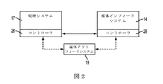
図2〜図3はさまざまな実施形態での切断機および媒体供給システム間の関係を示す。図2の実施形態では、切断機は切断ナイフを含む切断システム17およびコントローラ26を含む。自動インフィーダは媒体インフィードシステム14およびコントローラ28を含む。自動アウトフィーダの一部である、媒体アウトフィードシステム19は媒体インフィードコントローラ、切断機コントローラ、または別のコントローラ(図示せず)により制御することができる。図2の実施例は既存の切断機を自動インフィードおよびアウトフィードシステムに統合するため改造される場合に使用することができる。図3の実施形態では、統合された媒体供給および切断システム23は単一のコントローラ25を有する。この実施形態は、例えば、追加の装置およびソフトウェアを組み込むために既存の切断機を適合させることにより、または統合された供給および切断システムを構築することにより使用することができる。
2-3 illustrate the relationship between the cutting machine and the media supply system in various embodiments. In the embodiment of FIG. 2, the cutting machine includes a
図4A〜図4Dに示されているように、本明細書に記載される一実施形態は10’として指定された自動供給切断システムである。自動インフィーダ14’は、リタード・フィード・アセンブリ30、リタード・フィード・アセンブリ30の上流にあるナッジャーロール36、および切断機16’内に媒体のシート24を供給するためのニップ44を形成する下流の一対のテイクアウェイロール40および42を必要に応じて含む。媒体のシートは多くの場合、必ずしもそうではないが、事前印刷である。リタード・フィード・アセンブリ30はテイクアウェイロール40および42に、および/または切断機16’内にシートを転送するためのニップ38を一緒に形成する駆動ロール32およびリタードロール34を含む。動作中にナッジャーロール36はインフィード容器12’からスタック22の最上位のシート24に接触し、スタック22からリタード・フィード・アセンブリ30に最上位のシート24を前進させるために回転させる。
As shown in FIGS. 4A-4D, one embodiment described herein is an automatic feed cutting system designated as 10 '. The automatic infeeder 14 'forms a
リタードロール34はシャフト52上での回転用に支持される円筒部50を含む。リタードロール34は必要に応じて二重供給シートを分離するために不可欠なスリップクラッチ(図示せず)を有する。スリップクラッチの技術の詳細は米国特許第5,435,538号に記載されている。
The retard roll 34 includes a
一対のテイクアウェイロール40および42はリタード・フィード・アセンブリ30の下流に配置され、上側バッフル74および中間バッフル76によりシートの上および下に規定された媒体搬送路70に沿って、切断機16’内に媒体のシート24を移動させる。図4A〜図4Cに示す実施形態では、媒体のシート24は前方フィード方向に移動する。図4A〜図4Dに示す実施形態では、上側バッフル74は横向き傾斜、若干S字曲線で上流端にあるSの上方凹部とを有する断面のシート状である。中間バッフル76は実質的に均一な幅の媒体経路を形成するために、上側バッフル74の上流部の形状に適合している。図4A〜図4Dに示す実施形態では、中間バッフル76は下側バッフル78に接続され、機能については以下に説明する。この実施形態では、中間バッフル76および下側バッフル78は一般的に横向きV字形の断面を有するシートから形成される。実施形態では、上側バッフル74は2つの部分、すなわち上側第1のバッフル74aおよび上側第2のバッフル74bから形成され、上側第2のバッフル74aは媒体を切断機内に向け、上側第2のバッフル74bは媒体のシートを切断面上に向ける。上側第2のバッフル74bは、例えば切断機16’に入る際に媒体詰まりが発生した場合媒体のシート24へのアクセスを容易にするためシャフト75に対して相対的に軸回転することができる。
A pair of takeaway rolls 40 and 42 are disposed downstream of the
切断機16’はハウジング79、切断面80、および切断機16’を通ってシート24を移動させるように構成されたニップ86を画定する一対の切断機ロール82および84を含む。シート24の前縁88が切断機16’に入った後、シート24はシートの前縁部がニップ86により拾い上げられるまでテイクアウェイロール40および42により(またはテイクアウェイロールが使用されていない場合リタード・フィード・アセンブリにより)切断機16内を移動する。シート24の前縁部が切断機ロール84および86間に配置された後、シートの後縁部90はテイクアウェイロール40および42を、および媒体搬送路70の下側バッフル76を越えて通過する。この時点で、シート24の後縁90は切断面80上に下向きに落下する。シート24は切断機ロール82および84を使用して切断機16’内に沿って移動し続ける。
The cutter 16 'includes a
第1の縁端センサ92はシート24の前縁88および/または後縁90を検知するように配置されている。実施形態では、後縁90がセンサ92を超えて通過した後、シートは所定の期間が経過して後縁90が切断面80上にくるまでフィーダから排出され続ける。一旦シート24全体が切断面80上に置かれると、シート24の移動方向は任意に反転させることができ、シート24の後縁90は下側バッフル78の下の媒体搬送路70の下に後方に誘導される。いくつかのケースではシート24の後縁90はインフィード容器12’に向かって上流へ切断面を効果的に拡張する拡張プラットフォーム102上のフィーダ16’から排出される。シート24はシートの前縁88が第2の縁端センサ96により検知されるまで逆方向に移動し続ける。切断用位置合わせプロセスを開始するためにシートが正確に位置決めされていると第2の縁端センサ96が判断した場合、シート24の移動は切断機ロール82および84の回転を停止させることにより停止する。シートは次に切断のために位置合わせされ、シートはデジタル切断ナイフやペン100でデジタル切断される。文書位置合わせシステムを含めて、従来のデジタル切断システムは使用することができる。採用されている切断機の種類に応じて、シートおよび/またはデジタル切断刃は切断処理中に移動する。
The
図4A〜図4Dに示すシステムの変形例では、センサ92および96の一方または両方を使用する代わりに、開ループシステム、または部分的な開ループシステムは、切断機16’内におよび/または切断機16’内で移動する媒体のシート24のシートサイズのデータおよびシート速度の計算を使用して、切断機16’内に媒体のシートを適切に位置決めするために使用することができる。他の変形例では、追加または代替のセンサは切断機16’内でシートの位置を検知するために使用することができる。
In a variation of the system shown in FIGS. 4A-4D, instead of using one or both of the
切断が完了した後、切断されたシートは切断機ロール82および84を使用して出力容器20’に排出される。シート24の排出を行うために、従来の切断機は切断機ロールにこの機能を実行させるためにプログラミングすることにより適応することができる。この場合、自動アウトフィーダ18’は切断機ロール82および84を含む。別の実施形態では、ロールの追加セット(図示せず)は媒体の切断シートを排出するために追加される。
After cutting is complete, the cut sheet is discharged into output container 20 'using cutter rolls 82 and 84. In order to eject the
図4A〜図4Dに示す実施形態では、切断面80はプラットフォームであり、第1の切断プラットフォーム101および切断面の上流側に後方に延びる、および必要に応じて切断機16’自体の上流側の外側に、切断機16’の上流側(インフィード容器側)にシートが入っていくようにシートを収容するために水平方向に延びる、延長プラットフォーム102を含む。対照的に、従来の手動供給切断機は通常切断機の下流側から供給される。拡張リーフ102は媒体のシート24の後縁部をシート24の後縁部が切断機16’に入る前に前縁部と同一平面にすることができる。上側バッフル74および中間バッフル76の構成の組み合わせである、この構成はリタード・フィード・アセンブリ30の下流側詰まりエラーを最小限にする。
In the embodiment shown in FIGS. 4A-4D, the cutting
いくつかのケースでは、切断機16’、または切断機16’よりも下流に配置されたコンポーネントは、文書を次元性形状に折り畳みし易くするために媒体に折り目や折り罫を付与する。いくつかの切断機は切断後に折り罫ステージを含む。既知の折り罫システムの非限定的な例は、2012年12月11日に米国特許第8,328,706号として発行された米国特許公開第2011/0152048号に記載されている。 In some cases, the cutting machine 16 'or a component located downstream of the cutting machine 16' imparts creases and creases to the media to facilitate folding the document into a dimensional shape. Some cutting machines include a crease stage after cutting. A non-limiting example of a known crease system is described in US Patent Publication No. 2011/0152048, issued December 11, 2012 as US Patent No. 8,328,706.
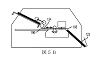
図5A〜図5Cはテイクアウェイロールが使用されない実施形態を概略的に示す。この構成では、全体的に110として指定される切断システムは、インフィード容器112、自動インフィーダ114、切断機116、自動アウトフィーダ118、および出力容器120を含む。インフィード容器112および出力容器120の部分は切断機116のハウジング179内に配置される。インフィード容器112および出力容器120は各々が媒体スタックを保持するように構成され、シート124のアンカットスタック122およびカットスタック123として示される。
5A-5C schematically illustrate an embodiment in which no takeaway roll is used. In this configuration, the cutting system designated generally as 110 includes an
自動インフィーダ114はリタード・フィード・アセンブリ130およびリタード・フィード・アセンブリ130から上流のナッジャーロール136を含む。リタード・フィード・アセンブリ130は駆動ロール132および切断機116内にシートを転送するためのニップ138を一緒に形成するリタードロール134を含む。動作中にナッジャーロール136はインフィード容器112からスタック122の最上位のシート124に接触し、最上位のシート124をスタック122からリタード・フィード・アセンブリ130に前進させるために回転させる。
The
リタードロール134はシャフト152上での回転用に支持される円筒部150を含む。リタードロールは二重供給シートの分離を容易にする。上記に示すように、スリップクラッチ技術の詳細は米国特許第5,435,538号に記載されている。
The
駆動ロール132およびリタードロール134は媒体のシート124を切断機116を通って前方に移動させるために回転させる。切断機116は切断面180および一対の切断ロール182。シート124はシートの前縁部が切断機ニップ186により拾い上げられるまで、駆動ロール132およびリタードロール134により切断機116を通って移動される。シート124の前縁部が切断機ロール182および184間に配置された後、シートの後縁190はリタード・フィード・アセンブリ130から排出される。この時点で、シート124の後縁190は切断面180から上流に延びる拡張プラットフォーム202上に下向きに落下する。シート124は切断機ロール182および184を使用して切断機116の内側に沿って移動し続ける。一旦切断プレート180上に水平に配置されると、シート124は位置合わせされ、デジタル切断ナイフ200で切断され、図4A〜図4Dに関連して上述されているのと同様であってもよい方法で排出される。上側バッフル、中間バッフルおよび下側バッフル(図5A〜図5Cには図示されず)はオプションであり、それぞれ図4A〜図4Dの実施例と同様の構成を一般的に有することができる。図4A〜図4Dの実施例で使用されるものと同種のセンサを使用することができ、および/または他の適切なセンサ配置を採用することができる。
前述したように、図5A〜図5Cに示す本実施形態では、リタード・フィード・アセンブリ130は切断面180の上流部の上部に垂直に切断機116内に配置される。この実施形態では、拡張プラットフォーム202は切断機116内側の第1の切断プラットフォーム201の上流側から上流方向に水平に延びる。シート124の後縁部はシート124の後端部が十分に切断機116の内部に入るまで前端部と同一平面にならない。
As described above, in the present embodiment shown in FIGS. 5A-5C, the
図1の実施例と同様に、図4および図5の実施形態は識別コードスキャナーなどのようなデータセンサを組み込むことができる。自動化のこの追加されたステップはさらに同じインフィード容器から媒体を利用するシーケンスで複数の異なった印刷ジョブの処理を高速化する。 Similar to the example of FIG. 1, the embodiments of FIGS. 4 and 5 may incorporate a data sensor such as an identification code scanner. This additional step of automation further speeds up the processing of multiple different print jobs in a sequence that utilizes media from the same in-feed container.
図6および図7に示すフローチャートは自動媒体供給および切断システムの動作を説明する。自動モードは図6に示され、そして一部自動、一部手動モードは図7で説明される。簡潔に明言され、図6で説明した自動方式では、個々の媒体シート(またはシートの一束内の最初のシート)には、デジタル切断にどのプログラムファイルが使用されるかを指定する識別コードが印刷されている。システムの電源がオンされた後、識別コードスキャナー28はスタックの一番上の媒体シート上のバーコードなどのような識別コードを読み取り、どのファイルが切断に使用されるべきであるかに関する信号をデジタル切断機に送信する。適切なファイルが選択され、ファイルが切断ナイフを動作させるために利用される。システムが一部手動モードで動作する時は、識別コードスキャナーは使用されない。オペレータが使用する切断プログラムを識別し、ホストPC(図8〜図9を参照)上にある切断ファイルをロードする。次に切断指示であるこのファイルが切断機に送信され、切断ファイルに含まれる指示に従いシートを切断する。
The flowcharts shown in FIGS. 6 and 7 illustrate the operation of the automatic media supply and cutting system. The automatic mode is illustrated in FIG. 6, and the partially automatic and partially manual modes are illustrated in FIG. In the automatic method, briefly stated and described in FIG. 6, each media sheet (or the first sheet in a bundle of sheets) has an identification code that specifies which program file is used for digital cutting. It is printed. After the system is powered on, the
より具体的には、図6に示すように、自動化プロセスは一般に300で指定される。オペレータは必要に応じて310で切断する文書の数を選択する。(いくつかの実施形態では、切断される文書の数を選択する代わりに、供給される媒体上の読み取り識別コードがなくなるまで、またはインフィード容器に媒体が存在しなくなるまで、フィードおよび切断機が動作する。)ジョブは「スタートボタン」を押すか、または別の方法で312で開始される。フィーダは314でオンになり、その結果316で媒体の最初のシートの自動供給となる。フィーダは多くの場合ナッジャーロールおよびリタード・フィード・アセンブリを含む。テイクアウェイロールは(含まれている場合)リタード・フィード・システムとともにオンになるか、または媒体の存在が検知された時に起動される。媒体は自動的にフィーダを使用して、一度に1枚供給される。シートが切断機に向かって移動している間に、センサ28(例えば、光学式スキャナーであってもよい)はシート上のデータを読み取り、対応する情報をコントローラに送信する。媒体のシートはその前縁が第1のセンサ318で検知されるまでシステム内を前方方向に移動する。媒体のシートは切断機ニップに入り、その前縁が切断機320の内側の第2のセンサで検知されるまで前進し続ける。第2のセンサによる検知後、シートの移動方向は多くの場合322で反転される。第2のセンサがシートを検知しない場合は、供給エラーが発生したと想定され、シート供給エラーが324で修正される。プロセスは312および314または316に戻り再始動する。
More specifically, as shown in FIG. 6, the automated process is generally designated 300. The operator selects the number of documents to be cut at 310 as needed. (In some embodiments, instead of selecting the number of documents to be cut, the feed and cutting machine may run until there is no read identification code on the supplied media or until there is no media in the in-feed container. The job is started at 312 by pressing the “start button” or otherwise. The feeder is turned on at 314, resulting in automatic feeding of the first sheet of media at 316. The feeder often includes a nudger roll and a retard feed assembly. Takeaway roll is turned on with the retard feed system (if included) or activated when the presence of media is detected. The media is automatically fed one at a time using the feeder. While the sheet is moving toward the cutter, sensor 28 (which may be an optical scanner, for example) reads the data on the sheet and sends the corresponding information to the controller. The sheet of media moves forward in the system until its leading edge is detected by the
シートの移動方向が322で反転される場合、第2のセンサによるシートの縁端検知によりシートが正しく位置合わせされるまで逆方向に移動する。この時点で、切断機ニップは326で停止する。識別コードが存在することが見出された場合、328に示すように、媒体からの(事前読み取りされた)識別コード情報は使用する適切な切断プログラムを決定するためにコントローラにより使用される。(識別コードが見出されなかった場合は、切断されていないシートが切断機ニップの順方向への回転により出力容器に338で排出される。)コントローラはどの切断プログラムが媒体を切断するために使用されるのかの信号を切断機に送信し、適切なシート位置合わせアルゴリズムが330で起動される。位置合わせ記号が332で見出された後、媒体は334でデジタル切断される。(位置合わせ記号の見出に問題がある場合は、おそらく位置合わせ不良の問題が発生し、シートが338で排出される。) When the moving direction of the sheet is reversed at 322, the sheet moves in the reverse direction until the sheet is correctly aligned by detecting the edge of the sheet by the second sensor. At this point, the cutter nip stops at 326. If an identification code is found to be present, the (pre-read) identification code information from the media is used by the controller to determine the appropriate cutting program to use, as shown at 328. (If no identification code is found, the uncut sheet is ejected to the output container at 338 by forward rotation of the cutter nip.) The controller determines which cutting program to cut the media. A signal as to whether it will be used is sent to the cutter and an appropriate sheet registration algorithm is activated at 330. After the alignment symbol is found at 332, the media is digitally cut at 334. (If there is a problem in finding the alignment symbol, there is probably a misalignment problem and the sheet is ejected at 338.)
一旦切断が完了すると、切断機ニップは切断シートを排出するために338で起動される。切断機ニップによるこの動作は、例えばアウトフィード容器に切断媒体を供給するのに切断機ニップを利用するように切断機コントローラをプログラミングすることにより、達成することができる。排出後、切断機ニップは340でオフにすることができる。ジョブ内にまだシートがあるかどうかの判断は342でされる。そうである場合、プロセスは316に戻る。そうでない場合、ジョブは344で終了する。 Once cutting is complete, the cutter nip is activated at 338 to eject the cut sheet. This operation by the cutter nip can be accomplished, for example, by programming the cutter controller to utilize the cutter nip to supply the cutting media to the outfeed container. After discharge, the cutter nip can be turned off at 340. A determination is made at 342 as to whether there are more sheets in the job. If so, the process returns to 316. Otherwise, the job ends at 344.
図6に示すプロセスの一変形例では、切断機内でのシートの位置決めは後方への移動を必要とせずに発生してもよい。この場合、シートの移動は通常、326で切断機ニップの回転を停止させることにより停止する。別の変形例では、フィード機構の異なるタイプが、例えば、真空フィード技術、特に媒体のシートを切断機に供給するため、および必要に応じて切断機内におよび外にシートを移動するためにも、プロセス内で使用される。 In a variation of the process shown in FIG. 6, the positioning of the sheet within the cutting machine may occur without requiring backward movement. In this case, the sheet movement is usually stopped by stopping the rotation of the cutter nip at 326. In another variant, different types of feed mechanisms are used, for example, for vacuum feed technology, in particular for feeding sheets of media to the cutter and for moving sheets into and out of the cutter as required. Used in the process.
図7に示し、400として指定される、一部手動動作システムの場合は、オペレータは411で切断プログラムを選択し、必要に応じて切断する文書の数を選択する(例えば、インフィード容器中の媒体シートの数が切断するシート数に等しくない限り)。ジョブは412で「スタートボタン」を押すか、または別の方法で開始される。フィーダは414でオンにされ(多くの場合ナッジャーロールおよびリタード・フィード・アセンブリも)、その結果416で媒体の最初のシートの自動供給となる。テイクアウェイロールは(含まれる場合)リタード・フィード・システムとともにオンになるか、または媒体の存在が検知された場合に起動される。リタードフィーダおよびテイクアウェイロールのニップを使用して、媒体は自動的に、一度に1シート供給される。媒体のシートはその前縁が第1のセンサ418で検知されるまでシステム内を前方に移動する。媒体のシートは、切断機ニップを通って、その前縁が420で切断機内側の第2のセンサで検知されるまで前進し続ける。第2のセンサによる検知後、シートの移動方向は多くの場合422で反転される。第2のセンサがシートを検知しない場合は、供給エラーが発生したと想定され、シート供給エラーが424で修正される。プロセスは412および414または416に戻り再始動する。
In the case of a partially manually operated system shown in FIG. 7 and designated as 400, the operator selects a cutting program at 411 and selects the number of documents to cut as needed (eg, in an in-feed container). Unless the number of media sheets is equal to the number of sheets to be cut). The job is started 412 by pressing the “start button” or otherwise. The feeder is turned on at 414 (often also a nudger roll and retard feed assembly), resulting in an automatic feed of the first sheet of media at 416. Takeaway roll is turned on with the retard feed system (if included) or activated when the presence of media is detected. The media is automatically fed one sheet at a time using the nip of the retard feeder and takeaway roll. The sheet of media moves forward in the system until its leading edge is detected by the
シートの移動方向が422で反転された後、第2のセンサによるシートの縁端検知によりシートが適切に位置合わせされるまで、シートは逆方向に移動する。この時点で、切断機ニップは426で停止する。適切なシート位置合わせアルゴリズムは411で選択された切断プログラムに基づいて430で起動される。位置合わせ記号が432で見出された後、媒体は434でデジタル切断される。(位置合わせ記号の見出に問題がある場合は、おそらく位置合わせ不良の問題が発生し、シートが438で排出される。) After the moving direction of the sheet is reversed at 422, the sheet moves in the reverse direction until the sheet is properly aligned by the edge detection of the sheet by the second sensor. At this point, the cutter nip stops at 426. An appropriate sheet registration algorithm is activated at 430 based on the cutting program selected at 411. After the alignment symbol is found at 432, the media is digitally cut at 434. (If there is a problem in finding the alignment symbol, there is probably a misalignment problem and the sheet is ejected at 438.)
一旦切断が完了すると、切断機ニップは切断シートを排出するために438で起動される。排出後、切断機ニップは440でオフにすることができる。ジョブ内にまだシートがあるかどうかの判断は442でされる。そうである場合、プロセスは416に戻る。そうでない場合、ジョブは444で終了する。 Once cutting is complete, the cutter nip is activated at 438 to eject the cut sheet. After discharge, the cutter nip can be turned off at 440. A determination is made at 442 whether there are more sheets in the job. If so, the process returns to 416. Otherwise, the job ends at 444.
図7に示すプロセスの一変形例では、切断機内でのシートの位置決めは後方への移動を必要とせずに発生してもよい。この場合、シートの移動は通常326で切断機ニップの回転を停止させることにより停止する。別の変形例では、フィード機構の異なるタイプが、例えば、真空フィード技術、特に媒体のシートを切断機に供給するため、および必要に応じて切断機内におよび外にシートを移動するためにも、プロセス内で使用される。 In a variation of the process shown in FIG. 7, the positioning of the sheet within the cutting machine may occur without requiring backward movement. In this case, the movement of the sheet is normally stopped at 326 by stopping the rotation of the cutter nip. In another variant, different types of feed mechanisms are used, for example, for vacuum feed technology, in particular for feeding sheets of media to the cutter and for moving sheets into and out of the cutter as required. Used in the process.
図8〜図9は、図2〜図3に示す供給および切断システムで使用するためのプログラム命令を実装するために使用できるコンピュータシステムの非限定的な例を表す。図2のシステムの特定の実施形態に対応する図8では、PCプロセッサ500、切断機プロセッサ502、およびフィーダプロセッサ501は、バスまたは他のデータ転送サブシステム504により相互接続される。バスまたは他のデータ転送サブシステム506は、PCプロセッサ500を、物理的なキーボードおよび/またはタッチスクリーンの形態であってもよいキーボード508、マウス510、メモリ512、ディスプレイ514および1つ以上のディスクドライブ516を含むさまざまなタイプの他のシステムコンポーネントと相互接続する。バスまたは他のデータ転送サブシステム518は、切断機プロセッサ502を、物理的なキーパッドおよび/またはタッチスクリーンの形態であってもよいキーパッド520、ディスプレイ522、メモリ524および1つ以上のディスクドライブ526を含むさまざまなタイプの他のシステムコンポーネントと相互接続する。バスまたは他のデータ転送サブシステム503は、フィーダプロセッサ501を、メモリ530と相互接続する。媒体は切断機プロセッサ502またはフィーダプロセッサ501を使用して切断機から取り除くことができる。図3のシステムに対応する図9では、統合化供給および切断用プロセッサ542は、バスまたは他のデータ転送サブシステム543により物理的なキーパッドおよび/またはタッチスクリーンの形態であってもよいキーパッド544、ディスプレイ546、メモリ548、および1つ以上のディスクドライブ550を含むさまざまなタイプの他のシステムコンポーネントと相互接続される。プロセッサ542はまたデータバス541を介してネットワーク540に接続される。図に示す電子的接続は選択した、および利用可能な技術に応じて有線または無線であることができる。
FIGS. 8-9 represent non-limiting examples of computer systems that can be used to implement program instructions for use in the feeding and cutting system shown in FIGS. In FIG. 8, corresponding to a particular embodiment of the system of FIG. 2, the
媒体ローディングシステムと統合する、または組み合わせることができるデジタル切断機の非限定的な例はGraphtec Craft Robo Pro、 Roland Desktop、 Cricut、 MakiおよびIolineを含む。このシステムで使用するために適合させることができるフィード技術の非限定的な例は、多機能印刷装置で使用されるバイパスフィーダの適合バージョンに組み込むことができるゼロックス(登録商標)リタードフィード技術である。 Non-limiting examples of digital cutting machines that can be integrated or combined with a media loading system include Graphtec Craft Robot Pro, Rollan Desktop, Cricut, Maki and Ioline. A non-limiting example of a feed technology that can be adapted for use with this system is the Xerox® retard feed technology that can be incorporated into an adapted version of a bypass feeder used in a multifunction printing device. .
図1〜図11に示す実施形態は、実行される切断の複雑さに応じて時間あたり媒体の5〜60シート、時間あたり10〜45シート、または時間あたり15〜30シートの範囲で切断するのに特に適している。 The embodiment shown in FIGS. 1-11 cuts in the range of 5-60 sheets of media per hour, 10-45 sheets per hour, or 15-30 sheets per hour, depending on the complexity of the cutting performed. Especially suitable for.
典型的なシステムは小規模プリントショップでシステムの使用が可能な、8〜25平方フィート、または10〜18平方フィート、または10〜15平方フィートの範囲で床面積を占める。システムが占める体積は典型的には20〜100立方フィート、または20〜60立方フィート、または20〜40立方フィートの範囲である。 Typical systems occupy floor space in the range of 8-25 square feet, or 10-18 square feet, or 10-15 square feet, which can be used in small print shops. The volume occupied by the system is typically in the range of 20-100 cubic feet, or 20-60 cubic feet, or 20-40 cubic feet.
上記したように、システムはプリントショップが経済的に競争力のある方法で小容量印刷ジョブ用の低価格次元性文書を生成することを可能にする。システムおよび方法は2から500個の範囲の小容量および短期の包装用途における使用に特によく適する。1〜500、または1〜250、または1〜100の範囲の印刷ジョブが説明されたシステムおよび方法を用いた切断によく適する。 As described above, the system allows print shops to generate low cost dimensionality documents for small volume print jobs in an economically competitive manner. The system and method are particularly well suited for use in small volumes ranging from 2 to 500 and short term packaging applications. Print jobs in the range 1-500, or 1-250, or 1-100 are well suited for cutting using the described systems and methods.
Claims (15)
切断面およびデジタル切断装置を含む媒体切断機と、
媒体のシートを支持するように構成された媒体インフィード容器と、
前記切断面に隣接して配置されるまたは接続される第1のフィーダであって、前記第1のフィーダは前記媒体切断機に向かって前記インフィード容器から個々の媒体のシートを自動的に搬送するように構成された第1のフィード装置を含む、前記第1のフィーダと、
前記切断面に媒体の個々のシートを位置決めするように構成されたポジショナであって、前記媒体切断機内に配置される第1のフィードニップを含む第2のフィード装置を含む前記ポジショナと、
切断された媒体のシートを受け取るように構成されたアウトフィード容器と、
前記切断面に隣接して配置されたまたは接続された第2のフィーダであって、前記第2のフィーダは切断された媒体のシートを前記媒体切断機から前記アウトフィード容器へ自動的に搬送するように構成された、前記第2のフィーダと、
前記媒体切断機、前記第1のフィーダ、前記ポジショナおよび前記第2のフィーダを動作するように構成されたプロセッサと、
前記シートのデータを読み取るように構成されたセンサをさらに含み、
自動モードでは、電源がオンされた後、前記センサは、スタックの一番上の前記シートにおける前記データに含まれる情報コードを読みとり、読みとった前記情報コードに対応して切断に使用されるべきファイルに関する信号を前記媒体切断機に送信し、
他方、一部手動モードでは、前記媒体切断機が、オペレータが識別した切断プログラムに対応する切断ファイルを受信する、媒体供給および切断システム。 A media supply and cutting system,
A media cutting machine including a cutting surface and a digital cutting device;
A media infeed container configured to support a sheet of media;
A first feeder located adjacent to or connected to the cutting surface, the first feeder automatically transporting individual media sheets from the infeed container towards the media cutting machine; The first feeder including a first feed device configured to:
A positioner configured to position individual sheets of media on the cutting surface, the positioner comprising a second feed device including a first feed nip disposed in the media cutter;
An outfeed container configured to receive a sheet of cut media;
A second feeder located adjacent to or connected to the cutting surface, wherein the second feeder automatically transports a sheet of cut media from the media cutting machine to the outfeed container; The second feeder configured as described above;
A processor configured to operate the media cutting machine, the first feeder, the positioner, and the second feeder;
Further comprising a sensor configured to read the data of the sheet;
In the automatic mode, after the power is turned on, the sensor reads the information code included in the data in the top sheet of the stack, and the file to be used for cutting corresponding to the read information code. A signal to the media cutting machine,
On the other hand, in a partially manual mode, the media supply and cutting system in which the media cutting machine receives a cutting file corresponding to the cutting program identified by the operator .
さらに、前記媒体切断機の内側に第2のセンサを備え、
前記シートは、前記シートの前記最初の縁端が前記第1のセンサで検知されるまで前方方向に移動した後、前記第1のフィードニップに入ってその最初の縁端が前記第2のセンサで検知されるまで前進しつづけ、
その最初の縁端が前記第2のセンサで検知された後、前記シートの移動方向が反転して、前記シートは、前記第2のセンサよる検知によって正しく位置あわせされるまで逆方向に移動し、
前記シートが正しく位置あわせされて、前記第1のフィードニップが停止した時点で、前記情報コードが存在するか否かが判定される、
請求項1に記載の媒体供給および切断システム。 The positioner viewed contains a first sensor for detecting the first edge of the sheet of media,
Furthermore, a second sensor is provided inside the medium cutting machine,
The sheet moves forward until the first edge of the sheet is detected by the first sensor, and then enters the first feed nip where the first edge is the second sensor. Keep moving forward until it is detected at
After the first edge is detected by the second sensor, the moving direction of the sheet is reversed, and the sheet moves in the reverse direction until it is correctly aligned by the detection by the second sensor. ,
When the sheet is correctly aligned and the first feed nip stops, it is determined whether the information code is present;
The media supply and cutting system according to claim 1.
媒体インフィード容器と、
デジタル切断機と、
前記デジタル切断機の一次側に後付けされるように構成された第1のフィーダであって、前記第1のフィーダは媒体の個々のシートを前記媒体インフィード容器から前記デジタル切断機に前方フィード方向に自動的に搬送するように構成された第1のフィード装置を含む、第1のフィーダと、
媒体アウトフィード容器と、
媒体の個々のシートを前記デジタル切断機から前記媒体アウトフィード容器に自動的に搬送するように構成された第2のフィーダと、
前記第1のフィーダ、前記第2のフィーダ、および前記デジタル切断機を動作するように構成されたプロセッサであって、前記プロセッサは、前記第1のフィーダを動作するように構成されたフィーダプロセッサを含み、前記フィーダプロセッサは、データ転送サブシステムにより前記切断機を動作するように構成された切断機プロセッサに接続された、前記プロセッサと、を備え、
前記媒体としてのシートのデータを読み取るように構成されたセンサをさらに含み、
自動モードでは、電源がオンされた後、前記センサは、スタックの一番上の前記シートにおける前記データに含まれる情報コードを読みとり、読みとった前記情報コードに対応して切断に使用されるべきファイルに関する信号を前記デジタル切断機に送信し、
他方、一部手動モードでは、前記デジタル切断機が、オペレータが識別した切断プログラムに対応する切断ファイルを受信する、媒体供給システム。 A medium supply system,
A medium infeed container;
A digital cutting machine,
A first feeder configured to be retrofitted to a primary side of the digital cutting machine, wherein the first feeder feeds individual sheets of media from the media infeed container to the digital cutting machine in a forward feed direction; A first feeder including a first feed device configured to automatically convey
A medium outfeed container;
A second feeder configured to automatically transport individual sheets of media from the digital cutter to the media outfeed container;
A processor configured to operate the first feeder, the second feeder, and the digital cutting machine, wherein the processor includes a feeder processor configured to operate the first feeder. The feeder processor comprising: a processor connected to a cutting machine processor configured to operate the cutting machine by a data transfer subsystem ;
A sensor configured to read data of the sheet as the medium;
In the automatic mode, after the power is turned on, the sensor reads the information code included in the data in the top sheet of the stack, and the file to be used for cutting corresponding to the read information code. Signal to the digital cutting machine,
On the other hand, in the partial manual mode, the digital cutting machine receives a cutting file corresponding to the cutting program identified by the operator .
第1のフィード装置を含む自動第1のフィーダを使用して個々のシートを保持するように構成されたインフィード容器から媒体のシートを取得するステップと、
前記第1のフィーダを使用して媒体のシートを前方フィード方向に第1および第2のバッフルとの間で前記切断面に自動的に移動するステップと、
前記切断面に媒体のシートを自動的に配置するステップと、
前記切断面上に所望の位置で媒体のシートを位置決めするために第2のフィード装置を使用して後方フィード方向に媒体のシートを移動するステップと、
媒体のシートを切断するステップと、
切断された媒体のシートを自動的に前記切断機外に供給するステップと、
アウトフィード容器に媒体のシートを放出するステップと、
センサで前記シートのデータを読み取るステップと、
自動モードでは、電源がオンされた後、前記センサが、スタックの一番上の前記シートにおける前記データに含まれる情報コードを読みとって、読みとった前記情報コードに対応して切断に使用されるべきファイルに関する信号を前記デジタル切断機に送信する一方、一部手動モードでは、前記デジタル切断機が、オペレータが識別した切断プログラムに対応する切断ファイルを受信するステップと、
を含む方法。 A method of supplying media to and from a cutting surface of a digital cutting machine, comprising:
Obtaining a sheet of media from an infeed container configured to hold individual sheets using an automatic first feeder including a first feed device;
Automatically moving a sheet of media to the cutting surface between the first and second baffles in a forward feed direction using the first feeder;
Automatically placing a sheet of media on the cut surface;
Moving the sheet of media in a backward feed direction using a second feed device to position the sheet of media at a desired position on the cut surface;
Cutting the sheet of media;
Automatically feeding the cut sheet of media out of the cutting machine;
Discharging a sheet of media into an outfeed container;
Reading the sheet data with a sensor;
In the automatic mode, after the power is turned on, the sensor should read the information code included in the data in the top sheet of the stack and be used for cutting corresponding to the read information code. Transmitting a signal relating to a file to the digital cutting machine, while in partial manual mode, the digital cutting machine receives a cutting file corresponding to a cutting program identified by an operator;
Including methods.
The method of claim 12 , wherein the second feed device includes a feed nip.
Applications Claiming Priority (2)
| Application Number | Priority Date | Filing Date | Title |
|---|---|---|---|
| US13/439,369 | 2012-04-04 | ||
| US13/439,369 US8827580B2 (en) | 2012-04-04 | 2012-04-04 | Media feeding system for cutting dimensional documents and methods of making and using same |
Publications (3)
| Publication Number | Publication Date |
|---|---|
| JP2013216096A JP2013216096A (en) | 2013-10-24 |
| JP2013216096A5 JP2013216096A5 (en) | 2016-04-21 |
| JP6037908B2 true JP6037908B2 (en) | 2016-12-07 |
Family
ID=49210087
Family Applications (1)
| Application Number | Title | Priority Date | Filing Date |
|---|---|---|---|
| JP2013060301A Expired - Fee Related JP6037908B2 (en) | 2012-04-04 | 2013-03-22 | Dimensional document cutting media supply system and method of manufacture and use thereof |
Country Status (6)
| Country | Link |
|---|---|
| US (1) | US8827580B2 (en) |
| JP (1) | JP6037908B2 (en) |
| CN (1) | CN103358346B (en) |
| BR (1) | BR102013007910A2 (en) |
| DE (1) | DE102013205515A1 (en) |
| MX (1) | MX2013003601A (en) |
Families Citing this family (5)
| Publication number | Priority date | Publication date | Assignee | Title |
|---|---|---|---|---|
| US10245803B2 (en) * | 2013-03-13 | 2019-04-02 | Xerox Corporation | Apparatus, system and method for cutting and creasing media |
| JP6218595B2 (en) * | 2013-12-25 | 2017-10-25 | キヤノン株式会社 | Sheet processing apparatus and image forming apparatus |
| JP6913478B2 (en) * | 2017-02-20 | 2021-08-04 | 株式会社Screenホールディングス | Printing equipment and printing method |
| CN108098920A (en) * | 2018-01-16 | 2018-06-01 | 宁波沃瑞印刷技术有限公司 | A kind of number page label die cutting machine |
| JP7322582B2 (en) * | 2019-08-09 | 2023-08-08 | 株式会社リコー | Sheet processing equipment, image forming system |
Family Cites Families (29)
| Publication number | Priority date | Publication date | Assignee | Title |
|---|---|---|---|---|
| US3866901A (en) | 1973-10-01 | 1975-02-18 | Xerox Corp | Reverse buckle feeder |
| US4368881A (en) | 1979-06-27 | 1983-01-18 | Savin Corporation | Friction paper feeder |
| JPH01101171A (en) * | 1987-10-09 | 1989-04-19 | Internatl Business Mach Corp <Ibm> | Continuous paper-cut paper feeder |
| US5275077A (en) | 1991-02-27 | 1994-01-04 | Mimaki Engineering Co., Ltd. | Method of forming perforated cut line by cutting plotter |
| JPH05132198A (en) * | 1991-11-06 | 1993-05-28 | Brother Ind Ltd | Manual paper feed device |
| JPH0544592U (en) | 1991-11-26 | 1993-06-15 | 武藤工業株式会社 | Automatic paper cutting device for plotter |
| JP3289153B2 (en) | 1992-11-11 | 2002-06-04 | 武藤工業株式会社 | Plotter sheet cutting method |
| AU5611394A (en) * | 1992-11-19 | 1994-06-08 | Dana-Farber Cancer Institute | Antibodies for gm-csf receptor and uses thereof |
| US5435538A (en) | 1994-01-03 | 1995-07-25 | Xerox Corporation | Retard roll with integral torque limiting slip clutch with reversing bias |
| US5829898A (en) * | 1995-08-29 | 1998-11-03 | Dynetics Engineering Corporation | Printing assembly with discrete load enhancement apparatus and method |
| US6109745A (en) * | 1998-07-17 | 2000-08-29 | Eastman Kodak Company | Borderless ink jet printing on receivers |
| JP4366547B2 (en) * | 1999-12-28 | 2009-11-18 | ブラザー工業株式会社 | Laminating equipment |
| US6664995B2 (en) | 2002-02-06 | 2003-12-16 | Brady Worldwide, Inc. | Label media-specific plotter cutter depth control |
| US6863273B2 (en) * | 2002-02-12 | 2005-03-08 | Bowe Bell & Howell Company | Document handling apparatus with dynamic infeed mechanism and related method |
| JP4107261B2 (en) * | 2003-11-14 | 2008-06-25 | セイコーエプソン株式会社 | Printer with cutter mechanism |
| JP4238811B2 (en) * | 2004-10-21 | 2009-03-18 | コニカミノルタビジネステクノロジーズ株式会社 | Paper cutting device and paper post-processing device |
| US7934718B2 (en) | 2005-03-24 | 2011-05-03 | Xerox Corporation | Sheet feeding of faster rate printing systems with plural slower rate sheet feeders |
| US7588245B2 (en) | 2005-11-03 | 2009-09-15 | Xerox Corporation | Friction retard sheet feeder |
| US7746524B2 (en) | 2005-12-23 | 2010-06-29 | Xerox Corporation | Bi-directional inverter printing apparatus and method |
| US7559549B2 (en) | 2006-12-21 | 2009-07-14 | Xerox Corporation | Media feeder feed rate |
| US8056897B2 (en) | 2007-03-29 | 2011-11-15 | Xerox Corporation | Moving sensor for sheet edge position measurement |
| JP4990001B2 (en) | 2007-03-30 | 2012-08-01 | 株式会社ミマキエンジニアリング | Printer / plotter device |
| US7731188B2 (en) | 2007-07-18 | 2010-06-08 | Xerox Corporation | Sheet registration system with auxiliary nips |
| US9132599B2 (en) | 2008-09-05 | 2015-09-15 | Xerox Corporation | System and method for image registration for packaging |
| JP2010188427A (en) | 2009-02-13 | 2010-09-02 | Mimaki Engineering Co Ltd | Cutting plotter and method of cut-plotting |
| CN102596772A (en) * | 2009-08-26 | 2012-07-18 | 博莱沃创新工艺公司 | Crafting apparatus including a workpiece feed path bypass assembly and workpiece feed path analyzer |
| JP2011121777A (en) * | 2009-12-14 | 2011-06-23 | Ricoh Elemex Corp | Paper feeding and conveying device |
| US8328706B2 (en) | 2009-12-17 | 2012-12-11 | Xerox Corporation | System and method for converting a printed substrate |
| US8316749B2 (en) * | 2010-05-13 | 2012-11-27 | Eastman Kodak Company | Finisher for cutting or scoring receiver |
-
2012
- 2012-04-04 US US13/439,369 patent/US8827580B2/en active Active
-
2013
- 2013-03-22 JP JP2013060301A patent/JP6037908B2/en not_active Expired - Fee Related
- 2013-03-27 MX MX2013003601A patent/MX2013003601A/en not_active Application Discontinuation
- 2013-03-27 DE DE102013205515A patent/DE102013205515A1/en not_active Withdrawn
- 2013-04-02 BR BRBR102013007910-3A patent/BR102013007910A2/en not_active Application Discontinuation
- 2013-04-03 CN CN201310115982.4A patent/CN103358346B/en not_active Expired - Fee Related
Also Published As
| Publication number | Publication date |
|---|---|
| CN103358346B (en) | 2019-01-22 |
| CN103358346A (en) | 2013-10-23 |
| MX2013003601A (en) | 2014-05-09 |
| US8827580B2 (en) | 2014-09-09 |
| DE102013205515A1 (en) | 2013-10-10 |
| US20130266358A1 (en) | 2013-10-10 |
| JP2013216096A (en) | 2013-10-24 |
| BR102013007910A2 (en) | 2015-06-16 |
Similar Documents
| Publication | Publication Date | Title |
|---|---|---|
| JP6037908B2 (en) | Dimensional document cutting media supply system and method of manufacture and use thereof | |
| US9802330B2 (en) | Document production system and method with automated die exchange | |
| US10245803B2 (en) | Apparatus, system and method for cutting and creasing media | |
| JP5695559B2 (en) | Method and apparatus for manufacturing package in digital control process | |
| JP5410354B2 (en) | Sheet processing device | |
| TWI534751B (en) | Ticket production device and ticket production method | |
| US10087035B2 (en) | Sheet post-processing device which folds a conveyed sheet at two or more positions | |
| JP4698363B2 (en) | Sheet processing apparatus and image forming apparatus | |
| JP4478397B2 (en) | Printing apparatus and printing method | |
| JP4861215B2 (en) | Sheet processing apparatus and image forming apparatus | |
| US11299365B2 (en) | Variable rotation of paddle for finisher | |
| US8313187B2 (en) | Modular RFID imaging device option | |
| JP2005096450A (en) | Recording apparatus and control method for its recording medium conveyance | |
| JP2007084269A (en) | Sheet treatment device and image forming device | |
| JP2005178001A (en) | Incorrect collating detecting machine utilizing non-contact ic tag, doble-feeding/page-missing detecting machine, bookbinding machine, method for detecting incorrect collating and method for detecting double-feeding/page-missing | |
| JP6218273B2 (en) | Collating machine and bookbinding system equipped with the collating machine | |
| JP2023148900A (en) | Binding device | |
| JP5176630B2 (en) | 3-form random binding machine | |
| JP5586643B2 (en) | Paper processing apparatus and paper conveying method | |
| JP5571723B2 (en) | Paper processing apparatus and paper conveying method | |
| JP3028968U (en) | Paper storage device | |
| JP2006188292A (en) | Paper feeder and printing system | |
| JP2007084159A (en) | Sheet handling device and image forming device | |
| JP2006212959A (en) | Image forming system | |
| JP2014019099A (en) | Image formation system, and communication control method for image formation system |
Legal Events
| Date | Code | Title | Description |
|---|---|---|---|
| A521 | Request for written amendment filed |
Free format text: JAPANESE INTERMEDIATE CODE: A523 Effective date: 20160303 |
|
| A621 | Written request for application examination |
Free format text: JAPANESE INTERMEDIATE CODE: A621 Effective date: 20160303 |
|
| A871 | Explanation of circumstances concerning accelerated examination |
Free format text: JAPANESE INTERMEDIATE CODE: A871 Effective date: 20160303 |
|
| A975 | Report on accelerated examination |
Free format text: JAPANESE INTERMEDIATE CODE: A971005 Effective date: 20160328 |
|
| A131 | Notification of reasons for refusal |
Free format text: JAPANESE INTERMEDIATE CODE: A131 Effective date: 20160524 |
|
| A521 | Request for written amendment filed |
Free format text: JAPANESE INTERMEDIATE CODE: A523 Effective date: 20160810 |
|
| TRDD | Decision of grant or rejection written | ||
| A01 | Written decision to grant a patent or to grant a registration (utility model) |
Free format text: JAPANESE INTERMEDIATE CODE: A01 Effective date: 20161011 |
|
| A61 | First payment of annual fees (during grant procedure) |
Free format text: JAPANESE INTERMEDIATE CODE: A61 Effective date: 20161101 |
|
| R150 | Certificate of patent or registration of utility model |
Ref document number: 6037908 Country of ref document: JP Free format text: JAPANESE INTERMEDIATE CODE: R150 |
|
| R250 | Receipt of annual fees |
Free format text: JAPANESE INTERMEDIATE CODE: R250 |
|
| R250 | Receipt of annual fees |
Free format text: JAPANESE INTERMEDIATE CODE: R250 |
|
| LAPS | Cancellation because of no payment of annual fees |