JP6032792B2 - Vehicle horn disc - Google Patents
Vehicle horn disc Download PDFInfo
- Publication number
- JP6032792B2 JP6032792B2 JP2012061593A JP2012061593A JP6032792B2 JP 6032792 B2 JP6032792 B2 JP 6032792B2 JP 2012061593 A JP2012061593 A JP 2012061593A JP 2012061593 A JP2012061593 A JP 2012061593A JP 6032792 B2 JP6032792 B2 JP 6032792B2
- Authority
- JP
- Japan
- Prior art keywords
- disk
- divided
- disc
- sound
- vibration
- Prior art date
- Legal status (The legal status is an assumption and is not a legal conclusion. Google has not performed a legal analysis and makes no representation as to the accuracy of the status listed.)
- Active
Links
- 230000005284 excitation Effects 0.000 claims description 9
- 230000002093 peripheral effect Effects 0.000 claims description 6
- 238000010586 diagram Methods 0.000 description 4
- 238000004458 analytical method Methods 0.000 description 2
- 239000012528 membrane Substances 0.000 description 2
- 241000282412 Homo Species 0.000 description 1
- 230000003321 amplification Effects 0.000 description 1
- 238000007796 conventional method Methods 0.000 description 1
- 238000005520 cutting process Methods 0.000 description 1
- 239000004615 ingredient Substances 0.000 description 1
- 238000009434 installation Methods 0.000 description 1
- 238000003698 laser cutting Methods 0.000 description 1
- 238000004519 manufacturing process Methods 0.000 description 1
- 238000000034 method Methods 0.000 description 1
- 238000003199 nucleic acid amplification method Methods 0.000 description 1
- 230000010355 oscillation Effects 0.000 description 1
Images


Classifications
-
- G—PHYSICS
- G10—MUSICAL INSTRUMENTS; ACOUSTICS
- G10K—SOUND-PRODUCING DEVICES; METHODS OR DEVICES FOR PROTECTING AGAINST, OR FOR DAMPING, NOISE OR OTHER ACOUSTIC WAVES IN GENERAL; ACOUSTICS NOT OTHERWISE PROVIDED FOR
- G10K9/00—Devices in which sound is produced by vibrating a diaphragm or analogous element, e.g. fog horns, vehicle hooters or buzzers
- G10K9/12—Devices in which sound is produced by vibrating a diaphragm or analogous element, e.g. fog horns, vehicle hooters or buzzers electrically operated
- G10K9/13—Devices in which sound is produced by vibrating a diaphragm or analogous element, e.g. fog horns, vehicle hooters or buzzers electrically operated using electromagnetic driving means
-
- B—PERFORMING OPERATIONS; TRANSPORTING
- B60—VEHICLES IN GENERAL
- B60Q—ARRANGEMENT OF SIGNALLING OR LIGHTING DEVICES, THE MOUNTING OR SUPPORTING THEREOF OR CIRCUITS THEREFOR, FOR VEHICLES IN GENERAL
- B60Q5/00—Arrangement or adaptation of acoustic signal devices
-
- G—PHYSICS
- G10—MUSICAL INSTRUMENTS; ACOUSTICS
- G10K—SOUND-PRODUCING DEVICES; METHODS OR DEVICES FOR PROTECTING AGAINST, OR FOR DAMPING, NOISE OR OTHER ACOUSTIC WAVES IN GENERAL; ACOUSTICS NOT OTHERWISE PROVIDED FOR
- G10K13/00—Cones, diaphragms, or the like, for emitting or receiving sound in general
Description
本発明は、車両用警音器のディスクに係り、より詳しくは、単一ディスクタイプの警音器で様々な周波数の音を発生させ、警音器の音色を柔らかいものに改善できる車両用警音器のディスクに関する。 The present invention relates to a vehicle horn disc, and more particularly, a single disc type horn generates various frequencies of sound and can improve the tone of the horn to a soft one. It relates to a sound disk.
通常の自動車には、緊急状況や、歩行者及び他の車両に対して警告が必要な場合に運転者の操作により警報音を発生させる警音器(Horn)が装着されている。
車両用警音器としては、ディスクタイプまたはシェルタイプの警音器が広く使われており、ディスクタイプはダイヤフラム及びディスク、そしてこれらを振動させるための電磁石を主要構成とし、ダイヤフラムの振動に連動して電磁石コイルへの電流を断続するための接点を有する。
A normal automobile is equipped with a horn that generates an alarm sound by a driver's operation in an emergency situation or when a warning is required for pedestrians and other vehicles.
As a vehicle sounding device, a disk type or shell type sounding device is widely used. The disk type mainly includes a diaphragm, a disk, and an electromagnet for vibrating the diaphragm, and interlocks with the vibration of the diaphragm. And a contact for interrupting current to the electromagnetic coil.
ディスクタイプの警音器は、主にディスクの振動により音を発生させるものであり、単一ディスクを用いる単一ディスクタイプ、または複数のディスクを用いる多重ディスクタイプの構成がある。
単一ディスクタイプの警音器については特許文献1〜3に開示されており、多重ディスクタイプの警音器については特許文献4,5に開示されている。
シェルタイプの警音器は、メンブレインにシェル状のホーンを被せて音の低周波成分を補強することで、メンブレインの振動とシェルの音響増幅により音を発生させる。
The disk type alarm sound is generated mainly by the vibration of the disk, and has a single disk type using a single disk or a multiple disk type structure using a plurality of disks.
Single disk type horns are disclosed in
A shell-type alarm sound is produced by covering a membrane with a shell-shaped horn to reinforce the low-frequency component of the sound, thereby generating sound by vibration of the membrane and acoustic amplification of the shell.
図1は従来のディスクタイプの警音器を示す構成図である。
図1に示したとおり、本体11の中心に凹込み溝11aが形成され、凹込み溝11a内にはポール(Pole)12が突出形成され、ポール12にはコイル13が巻き取られる。
また、本体11の周縁部に沿ってダイヤフラム14が結合され、ダイヤフラム14から上側に離隔配置されるディスク15がアーマチュア(armature)16により固定され、アーマチュア16はポール12の上側に離隔配置される。
また、本体11の内部一側にはスタンド17と板ばね18の一端が一緒に固定され、スタンド17と板ばね18は他側に延びてスタンド17と板ばね18の間に接点19を形成する。
このような構成でバッテリー(B)の(+)電源はスタンド17に電気的に接続され、接地された作動スイッチ(HS)を有する配線はコイル13となり最終的に板ばね18に電気的に接続される。
ディスク15、ダイヤフラム14、及びアーマチュア16は、1つの振動子を構成し、この振動子が速く振動することにより音が発生する。
FIG. 1 is a block diagram showing a conventional disk type alarm.
As shown in FIG. 1, a
In addition, a
One end of the
With this configuration, the (+) power source of the battery (B) is electrically connected to the
The
単一ディスクタイプの警音器は、音の主要周波数成分(共振周波数)が3kHz付近に位置して音が鋭く、音色が劣る問題がある。
人が聞くことができる音の周波数は20Hz〜20kHzの区間である。また、人の耳が最も敏感に感じる区間は2kHz〜5kHzの区間で、その区間の音は非常に鋭く聞こえる。
一方、多重ディスクタイプの警音器は複数のディスクを用いるため、様々な周波数成分を有する和音を発生させて単一音が与える不快感をある程度低減できるが、単一ディスクタイプの警音器に比べて複数のディスクによる重量増加とコストアップの問題がある。
また、シェルタイプの警音器は、2kHz未満の様々な周波数成分の音を発生させて音があまり鋭くないという利点はあるが、1車両当たり1つのディスクを使用するディスクタイプとは異なり、音圧に対する規制があって音が小さくなるため、車両ごとに2つずつ装着しなければならず、それによって、ディスクタイプよりも設置費用が高くなるという問題がある。
The single disk type horn has a problem that the main frequency component (resonance frequency) of the sound is located near 3 kHz, the sound is sharp, and the timbre is inferior.
The frequency of the sound that can be heard by humans is in the range of 20 Hz to 20 kHz. In addition, the section where the human ear feels most sensitive is a section of 2 kHz to 5 kHz, and the sound in that section sounds very sharp.
On the other hand, since the multi-disc type horn uses a plurality of discs, it is possible to generate a chord having various frequency components to reduce the discomfort given by a single sound to some extent. In comparison, there are problems of weight increase and cost increase due to multiple disks.
In addition, the shell type horn has the advantage that it produces sounds with various frequency components below 2 kHz and the sound is not very sharp, but unlike the disc type that uses one disc per vehicle, Since there is a restriction on the pressure and the sound is reduced, there is a problem that two vehicles must be installed for each vehicle, which causes a higher installation cost than the disk type.
本発明は上記の問題を解決するためになされたものであって、その目的とするところは、単一ディスクタイプの警音器で様々な周波数成分の音を発生させて警音器の音色を柔らかいものに改善できる車両用警音器のディスクを提供することにある。 The present invention has been made to solve the above-mentioned problems, and the object of the present invention is to generate sounds of various frequency components with a single disk type audible alarm and to change the tone of the audible alarm. The object is to provide a vehicle horn disc that can be improved to be soft.
上記の目的を達成するためになされた本発明の車両用警音器のディスクは、
車両用警音器のディスクであって、
ディスクの全領域が、振動特性が相異なる複数の領域に分割され、前記複数の領域が前記ディスクの円周方向に沿って配置された構造を有し、
前記複数の領域は、相異なる面積を有するように分割形成されたことにより、相異なる振動特性を有し、前記ディスクの外周縁から中心に向かって長く形成された切開部が形成されて分割された構造であり、
共振周波数は、各分割領域の面積によって異なることを特徴とする。
In order to achieve the above-mentioned object, the disk of the vehicle horn according to the present invention,
A vehicle horn disc,
The entire area of the disk is divided into a plurality of areas having different vibration characteristics, and the plurality of areas are arranged along the circumferential direction of the disk,
The plurality of regions are divided and formed so as to have different areas, so that they have different vibration characteristics, and an incision part formed long from the outer peripheral edge of the disk toward the center is formed and divided. Structure
Resonant frequency, characterized by a different this by the area of each divided region.
前記切開部は、ディスクの外周縁から中心に向かって半径方向に沿って長く形成され、
前記ディスクの振動により発生する音の周波数成分は、「加振力周波数成分×ディスク振動周波数成分」で表され、加振力は、ディスクの中心点に適用されることを特徴とする。
The incision is formed long along the radial direction from the outer peripheral edge of the disc toward the center,
The frequency component of the sound generated by the vibration of the disc is represented by “excitation force frequency component × disc oscillation frequency component”, and the excitation force is applied to the center point of the disc.
本発明のディスクを単一ディスクタイプの警音器に適用する場合、ディスクの非均等分割構造により、様々な周波数成分の音を発生させ、振動時に多数の共振周波数を有するため、警音器の音色を改善することができ、それによって車両の高級化を達成することができる。
また、本発明のディスクを用いた場合、従来の多重ディスクタイプの警音器及びシェルタイプの警音器に比べて重量及び費用の低減が可能となり、従来の問題を解消することができる。
When the disc of the present invention is applied to a single disc type horn, since the sound of various frequency components is generated by the non-uniform division structure of the disc and has many resonance frequencies during vibration, The timbre can be improved, and thereby the upgrading of the vehicle can be achieved.
Further, when the disc of the present invention is used, the weight and cost can be reduced as compared with the conventional multi-disc type alarm and shell type alarm, and the conventional problems can be solved.
以下、添付した図面を参照して本発明の実施例について詳細に説明する。
本発明は、単一ディスクタイプの警音器に用いられるディスクに関するものであって、様々な周波数の音を発生させることができ、警音器の音色を改善して高級感を味わうことができる車両用警音器のディスクに関する。
Hereinafter, embodiments of the present invention will be described in detail with reference to the accompanying drawings.
The present invention relates to a disk used for a single disk type horn, can generate sounds of various frequencies, and can improve the timbre of the horn and enjoy a high-class feeling. The present invention relates to a vehicle sounder disc.
本発明のディスクは、振動時に多数の共振周波数を有するようにその形状を改善し、それによって、従来のディスクに比べて柔らかい音を発生させることができる。
このような本発明のディスクを使用する場合、従来の多重ディスクタイプの警音器及びシェルタイプの警音器に比べて重量及び費用の低減が可能となるため、本発明は、従来の問題が解消された単一ディスクタイプの警音器を提供することができる。
The disk of the present invention is improved in its shape so as to have a large number of resonance frequencies during vibration, thereby generating a softer sound than the conventional disk.
When such a disc of the present invention is used, since the weight and cost can be reduced as compared with the conventional multi-disc type horn and shell type horn, the present invention has the conventional problems. It is possible to provide a single disk type alarm sound which is eliminated.
図2は本発明の実施例による警音器用ディスクの平面図であり、図3は本発明の実施例による警音器用ディスクの断面図である。
本発明のディスク20は、平面上で見た時、円形の構造を有する従来の形状を改良して図2に示したとおり様々な領域に分割された花びら状に製作される。
具体的には、本発明のディスク20は外周縁から中心21に向かって長く形成された切開部22により、全体形状が複数の領域23a〜23cに分割され、花びら状に分割された各領域23a〜23cがそれぞれ振動特性が相異なる構造を有する。
FIG. 2 is a plan view of a sounder disk according to an embodiment of the present invention, and FIG. 3 is a cross-sectional view of a sounder disk according to an embodiment of the present invention.
The
Specifically, the
ここで、ディスク20の中心21は、図1に示した警音器1においてアーマチュア16に結合される部分であり、それによって、本発明のディスク20は各分割領域が円周方向に沿って配置される構造となる。
この時、切開部22は、複数形成され、通常外周縁から中心方向に、半径に沿って長く形成される。複数の切開部22により2個以上の分割領域が形成される。
また、切開部22が形成されていない位置におけるディスク20の断面形状は、図3に示したとおり、公知のディスク15の断面形状とほぼ同じ形状である。
さらに、各分割領域の振動特性を異なるものにするために、本発明のディスク20は切開部22により分割された各領域23a〜23cの面積A1〜A3が相異なる非均等分割される。各分割領域23a〜23cの面積が異なる(A1≠A2、A1≠A3、A2≠A3)ため、分割領域ごとに共振周波数が異なることになる。
このように本発明は、ディスク20が非均等に分割された構造に形成されたことに主な特徴がある。
Here, the
At this time, a plurality of
Further, the cross-sectional shape of the
Furthermore, in order to make the vibration characteristics of the divided areas different, the
As described above, the present invention is mainly characterized in that the
上記構成において、分割領域23a〜23cのうちの一部または全体面積A1〜A3が同一である場合(A1=A2、A1=A3、A1=A2=A3など)、すなわちディスク20を均等に分割する場合、同一面積の分割領域が同じ周波数成分を有することになるため、警音器の音質及び音色を改善しようとする本発明の目的を達成しにくい。
In the above configuration, when a part of the divided
上記の実施例では、ディスク20に計3個の切開部22を形成し、面積が異なる3個の領域23a〜23cに分割したが、切開部をさらに少なくまたは多く形成して2個の領域または4個、5個の領域に分割してもよい。
例えば、切開部22を2個形成して2個の領域に分割するか、または切開部を4個形成して4個の領域に分割することができる(図5の(b)参照)。
また、他の実施例として、各分割領域の面積を分割し、分割領域の面積比を1:0.5(分割領域2個)、または1:0.5:0.25(分割領域3個)、または1:0.8:0.6:0.4:0.2(分割領域5個)にしてもよい。
このように本発明のディスクは、切開部及び分割領域の個数、分割領域の面積比、切開部の位置などを多様に変更することができる。
In the above embodiment, a total of three
For example, two
As another embodiment, the area of each divided region is divided, and the area ratio of the divided regions is 1: 0.5 (two divided regions) or 1: 0.5: 0.25 (three divided regions). ), Or 1: 0.8: 0.6: 0.4: 0.2 (5 divided areas).
As described above, the disc of the present invention can be variously changed in the number of incisions and divided areas, the area ratio of the divided areas, the position of the incisions, and the like.
上記の分割構造のディスクを製造する方法は、従来のディスクを機械加工して各分割線に沿って切開する方法を用いてもよいが、多くの場合、切開のための加工手段としてはレーザ切削、水圧切削などの方法が用いられる。
このように非均等分割構造のディスクを使用すると、従来の非分割ディスクに比べてあまり鋭くない音を発生させるが、分割された領域がそれぞれ異なる共振周波数を有するため、音の周波数成分が3個以上に増加し、それによって、より柔らかい音を発生させることができる。
The above-described method of manufacturing a disc having a divided structure may be a conventional method in which a disc is machined and incised along each dividing line, but in many cases, laser cutting is used as a processing means for incision. A method such as hydraulic cutting is used.
When a disc with a non-uniformly divided structure is used in this way, a sound that is not so sharp as compared to a conventional non-divided disc is generated. However, since the divided regions have different resonance frequencies, there are three sound frequency components. More than that, a softer sound can be generated.
上述のとおり、人が聞くことができる音の周波数成分は20Hz〜20kHzの区間である。また、人の耳が最も敏感に感じる区間は2kHz〜5kHz区間で、その区間の音は非常に鋭く聞こえる。
また、一般的な音は様々な周波数成分で構成され、この時、2kHz〜5kHzでの周波数成分が大きい場合は耳に鋭く聞こえ、それよりも低い周波数成分が混ざっている場合はより柔らかく聞こえる。
As described above, the frequency component of the sound that a person can hear is a section of 20 Hz to 20 kHz. In addition, the section in which the human ear feels most sensitive is the 2 kHz to 5 kHz section, and the sound in that section sounds very sharp.
A general sound is composed of various frequency components. At this time, when the frequency component at 2 kHz to 5 kHz is large, the sound is heard sharply, and when a frequency component lower than that is mixed, it sounds softer.
警音器は、主にディスクの振動により音が発生するが、発生する音には、図4に示したとおり、約350Hz(加振力の1次高調波(Harmonic))及びその倍数の周波数成分が存在する。
この時、従来の非分割ディスク構造では、ディスクの振動モードが位置している3kHz帯域で高い値を有し、それによって、振動時の音が鋭く聞こえる。
音の周波数成分は、「加振力周波数成分×ディスク振動周波数成分」で表すことができ、ディスク振動周波数成分はディスクの共振周波数のうち、大きい値を有する。
そのため、音の周波数成分を修正する場合、ディスクの共振周波数を修正しなければならない。
The sound generator generates sound mainly due to the vibration of the disk. As shown in FIG. 4, the generated sound is about 350 Hz (first harmonic of the excitation force (Harmonic)) and its multiple frequency. Ingredients are present.
At this time, the conventional non-divided disk structure has a high value in the 3 kHz band where the vibration mode of the disk is located, so that the sound during vibration can be heard sharply.
The frequency component of the sound can be expressed as “excitation force frequency component × disc vibration frequency component”, and the disc vibration frequency component has a large value among the resonance frequencies of the disc.
Therefore, when correcting the frequency component of the sound, the resonance frequency of the disk must be corrected.
従来の非分割ディスク構造では、音が3kHz帯域で高い値を有する。より柔らかく聞こえるためには、ディスクの共振周波数が2kHz未満の帯域に高い値が存在しなければならない。
したがって、ディスクを分割して2kHz未満で共振周波数をさらに発生させると、2kHz未満で音がブースティング(Boosting)してより柔らかい音を発生させることができる。
In the conventional non-divided disk structure, the sound has a high value in the 3 kHz band. In order to sound softer, there must be a high value in the band where the resonant frequency of the disk is less than 2 kHz.
Therefore, when the disk is divided and a resonance frequency is further generated at less than 2 kHz, the sound can be boosted at less than 2 kHz to generate a softer sound.
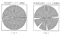
図5は従来のディスク(a)と本発明の非均等分割ディスク(b)に対する振動解析用モデルの例を示す図面であり、図6のグラフは図5の各ディスクが中心点に水平方向の加振力を受けた時、Z方向(図3の垂直方向)の振動エネルギーを示す図面である。
従来の非分割ディスクは、図6に示したとおり、2個の主要ピークが存在するが、非均等分割ディスクでは5個の主要ピークが存在するため、Z方向の加振に反応する共振周波数が非分割ディスクに比べて非均等分割ディスクにさらに多く存在することを推定することができる。
実際ディスクの共振周波数は、表1に示したとおり、振動ピークよりも多い。しかし、ディスクの加振力(垂直方向)に反応する共振周波数は非分割ディスクでは2個、非均等分割ディスクでは5個であって、あまり多くない。
FIG. 5 is a diagram showing an example of a vibration analysis model for the conventional disk (a) and the non-uniformly divided disk (b) of the present invention. The graph of FIG. 6 is a graph in which each disk of FIG. It is drawing which shows the vibration energy of a Z direction (vertical direction of FIG. 3) when receiving an excitation force.
As shown in FIG. 6, the conventional non-divided disk has two main peaks, but the non-uniform divided disk has five main peaks, and therefore the resonance frequency that reacts to the vibration in the Z direction is low. It can be estimated that there are more non-uniformly divided disks than non-divided disks.
Actually, as shown in Table 1, the resonance frequency of the disk is larger than the vibration peak. However, the resonance frequency that responds to the excitation force (vertical direction) of the disk is two for the non-divided disk and five for the non-uniformly divided disk, which is not so many.

また、非均等分割ディスクの主要振動モードでは、非分割ディスクモードの分割を観察できるが、図7に示したとおり、非分割ディスクの1次主要モードは非均等分割ディスクの1次及び2次の主要モードに分割され、非分割ディスクの2次主要モードは非均等分割ディスクの3次、4次、5次の主要モードに分割される。
これは分割ディスクの分割領域がそれぞれ異なる振動特性を有するからであり、ディスクの非均等分割によるものである。
Further, in the main vibration mode of the non-uniformly divided disk, the division of the non-divided disk mode can be observed, but as shown in FIG. 7, the primary main mode of the non-divided disk is the primary and secondary of the non-uniformly divided disk. The main mode is divided, and the secondary main mode of the non-divided disk is divided into the third, fourth and fifth main modes of the non-uniformly divided disk.
This is because the divided areas of the divided disks have different vibration characteristics, and are due to non-uniform division of the disks.
本発明による非均等分割構造のディスクを使用すると、従来の非分割ディスクを使用する場合に比べて、様々な周波数成分の音を発生でき、それによって、音をより柔らかいものに改善することができる。 The use of the disc with the non-uniform division structure according to the present invention can generate sounds of various frequency components compared to the case of using the conventional non-division disc, thereby improving the sound to be softer. .
以上、本発明に関する好ましい実施形態について説明したが、本発明は上述した実施形態に限定されるものではなく、本発明の実施形態から当該発明が属する技術分野において通常の知識を有する者によって容易に変更され、均等であると認められる範囲のすべての変更を含む。 The preferred embodiments related to the present invention have been described above. However, the present invention is not limited to the above-described embodiments, and can be easily performed by those having ordinary knowledge in the technical field to which the present invention belongs from the embodiments of the present invention. Includes all changes that are changed and found to be equal.
1 警音器
11 本体
11a 凹込み溝
12 ポール
13 コイル
14 ダイヤフラム
15 (従来の非分割)ディスク
16 アーマチュア
17 スタンド
18 板ばね
19 接点
20 (本発明の非均等分割)ディスク
21 中心
22 切開部
23a,23b,23c 分割領域
A1,A2,A3 分割領域の面積
B バッテリー
HS 作動スイッチ
DESCRIPTION OF
Claims (3)
ディスクの全領域が、振動特性が相異なる複数の領域に分割され、前記複数の領域が前記ディスクの円周方向に沿って配置された構造を有し、
前記複数の領域は、相異なる面積を有するように分割形成されたことにより、相異なる振動特性を有し、前記ディスクの外周縁から中心に向かって長く形成された切開部が形成されて分割された構造であり、
共振周波数は、各分割領域の面積によって異なることを特徴とする車両用警音器のディスク。 A vehicle horn disc,
The entire area of the disk is divided into a plurality of areas having different vibration characteristics, and the plurality of areas are arranged along the circumferential direction of the disk,
The plurality of regions are divided and formed so as to have different areas, so that they have different vibration characteristics, and an incision part formed long from the outer peripheral edge of the disk toward the center is formed and divided. Structure
Resonant frequency, the disk of a vehicle horn, wherein the different this by the area of each divided region.
れたことを特徴とする請求項1に記載の車両用警音器のディスク。 2. The vehicle sounder disk according to claim 1 , wherein the incision portion is formed to extend in a radial direction from an outer peripheral edge of the disk toward a center. 3.
Applications Claiming Priority (2)
| Application Number | Priority Date | Filing Date | Title |
|---|---|---|---|
| KR1020110132541A KR101293987B1 (en) | 2011-12-12 | 2011-12-12 | Disk of horn for vehicle |
| KR10-2011-0132541 | 2011-12-12 |
Publications (2)
| Publication Number | Publication Date |
|---|---|
| JP2013122568A JP2013122568A (en) | 2013-06-20 |
| JP6032792B2 true JP6032792B2 (en) | 2016-11-30 |
Family
ID=48464844
Family Applications (1)
| Application Number | Title | Priority Date | Filing Date |
|---|---|---|---|
| JP2012061593A Active JP6032792B2 (en) | 2011-12-12 | 2012-03-19 | Vehicle horn disc |
Country Status (6)
| Country | Link |
|---|---|
| US (1) | US8689723B2 (en) |
| JP (1) | JP6032792B2 (en) |
| KR (1) | KR101293987B1 (en) |
| CN (1) | CN103165123B (en) |
| DE (1) | DE102012204584A1 (en) |
| IN (1) | IN2012DE00811A (en) |
Families Citing this family (3)
| Publication number | Priority date | Publication date | Assignee | Title |
|---|---|---|---|---|
| JP5916931B1 (en) * | 2015-07-28 | 2016-05-11 | 衆智達技研株式会社 | Electronic horn |
| JP6249074B1 (en) * | 2016-09-30 | 2017-12-20 | マツダ株式会社 | Horn resonance tube and horn with the same |
| KR102394806B1 (en) * | 2017-11-29 | 2022-05-04 | 현대자동차주식회사 | Device for operating horn of vehicle |
Family Cites Families (16)
| Publication number | Priority date | Publication date | Assignee | Title |
|---|---|---|---|---|
| JPS59131299A (en) * | 1983-12-12 | 1984-07-28 | Tatsuo Fukami | Piezoelectric electroacoustic transducer |
| JPS61249097A (en) * | 1985-04-26 | 1986-11-06 | 株式会社デンソー | Alarm for vehicle |
| JP2773889B2 (en) * | 1989-03-15 | 1998-07-09 | 松下電器産業株式会社 | Piezoelectric sounder |
| JP2949643B2 (en) * | 1990-11-22 | 1999-09-20 | 日通工株式会社 | Digitally driven piezoelectric speaker |
| JPH06186981A (en) * | 1992-12-18 | 1994-07-08 | Nissan Motor Co Ltd | Alarming horn |
| KR19980027870U (en) * | 1996-11-19 | 1998-08-05 | 오상수 | Assembly structure of car horn |
| KR19990035167A (en) | 1997-10-31 | 1999-05-15 | 양재신 | Auxiliary horn method of vehicle |
| JPH11143475A (en) * | 1997-11-12 | 1999-05-28 | Mitsuba Corp | Horn |
| KR100346555B1 (en) | 1999-12-20 | 2002-07-27 | 이무원 | Klaxon system for car |
| KR100391317B1 (en) | 2001-04-30 | 2003-07-12 | 현대자동차주식회사 | Horn using chord for automobile |
| JP3799001B2 (en) * | 2001-09-10 | 2006-07-19 | 富士彦 小林 | Piezoelectric speaker |
| US20050179523A1 (en) * | 2004-02-13 | 2005-08-18 | Chao-Ning Chiang | Dual sound coil structure for a sounder device |
| KR100757249B1 (en) | 2006-07-18 | 2007-09-10 | 현대자동차주식회사 | Adjustment device of horn point for cars |
| CN101909231A (en) * | 2009-06-03 | 2010-12-08 | 富准精密工业(深圳)有限公司 | Sound film and speaker employing same |
| KR101635021B1 (en) * | 2010-01-29 | 2016-07-01 | 엘지전자 주식회사 | Receiver module and portable terminal having the same |
| KR101308178B1 (en) | 2010-08-06 | 2013-09-16 | 이보형 | Improved endurance for Automobile Horn |
-
2011
- 2011-12-12 KR KR1020110132541A patent/KR101293987B1/en active IP Right Grant
-
2012
- 2012-03-19 JP JP2012061593A patent/JP6032792B2/en active Active
- 2012-03-20 IN IN811DE2012 patent/IN2012DE00811A/en unknown
- 2012-03-20 US US13/424,840 patent/US8689723B2/en active Active
- 2012-03-22 DE DE102012204584A patent/DE102012204584A1/en active Pending
- 2012-03-30 CN CN201210131122.5A patent/CN103165123B/en not_active Expired - Fee Related
Also Published As
| Publication number | Publication date |
|---|---|
| US20130145982A1 (en) | 2013-06-13 |
| KR20130065928A (en) | 2013-06-20 |
| KR101293987B1 (en) | 2013-08-07 |
| CN103165123B (en) | 2018-11-06 |
| IN2012DE00811A (en) | 2015-08-21 |
| DE102012204584A1 (en) | 2013-06-13 |
| US8689723B2 (en) | 2014-04-08 |
| CN103165123A (en) | 2013-06-19 |
| JP2013122568A (en) | 2013-06-20 |
Similar Documents
| Publication | Publication Date | Title |
|---|---|---|
| JP5344016B2 (en) | Vehicle presence reporting device | |
| JP5206762B2 (en) | Vehicle alarm device | |
| JP5029706B2 (en) | Vehicle presence notification device | |
| US9580010B2 (en) | Vehicle approach notification apparatus | |
| JP2012148642A (en) | Vehicle approach notification system | |
| US20130093578A1 (en) | Vehicle existence annunciator device and method for controlling the same | |
| JP2013166538A (en) | Vehicle presence notification apparatus | |
| JP6032792B2 (en) | Vehicle horn disc | |
| JPWO2019211990A1 (en) | Vibration control device | |
| JP2013216168A (en) | Vehicle existence notifying device | |
| WO2019080505A1 (en) | Active noise reduction method and system, and new energy vehicle | |
| JP5626787B2 (en) | Speaker | |
| US20240034230A1 (en) | Vehicle warning system | |
| JP6449332B2 (en) | Speaker device | |
| JP2022089801A (en) | Glasses with parametric audio unit | |
| JP6007894B2 (en) | Siren sound output device | |
| KR101836522B1 (en) | Disk of horn for vehicle | |
| JP4445182B2 (en) | Speaker device | |
| CN220234951U (en) | Mask of tweeter and tweeter | |
| KR100391317B1 (en) | Horn using chord for automobile | |
| JP7256992B2 (en) | Vehicle proximity notification device | |
| JP7049904B2 (en) | Vibration control device | |
| EP4304896A1 (en) | Vehicle warning system with feedback | |
| JPH08185187A (en) | Alarming horn for vehicle and alarming system for vehicle | |
| JP2012126206A (en) | Sound generator, and vehicle presence notification apparatus |
Legal Events
| Date | Code | Title | Description |
|---|---|---|---|
| A621 | Written request for application examination |
Free format text: JAPANESE INTERMEDIATE CODE: A621 Effective date: 20150306 |
|
| A977 | Report on retrieval |
Free format text: JAPANESE INTERMEDIATE CODE: A971007 Effective date: 20160121 |
|
| A131 | Notification of reasons for refusal |
Free format text: JAPANESE INTERMEDIATE CODE: A131 Effective date: 20160209 |
|
| A521 | Request for written amendment filed |
Free format text: JAPANESE INTERMEDIATE CODE: A523 Effective date: 20160506 |
|
| TRDD | Decision of grant or rejection written | ||
| A01 | Written decision to grant a patent or to grant a registration (utility model) |
Free format text: JAPANESE INTERMEDIATE CODE: A01 Effective date: 20161018 |
|
| A61 | First payment of annual fees (during grant procedure) |
Free format text: JAPANESE INTERMEDIATE CODE: A61 Effective date: 20161021 |
|
| R150 | Certificate of patent or registration of utility model |
Ref document number: 6032792 Country of ref document: JP Free format text: JAPANESE INTERMEDIATE CODE: R150 |
|
| R250 | Receipt of annual fees |
Free format text: JAPANESE INTERMEDIATE CODE: R250 |
|
| R250 | Receipt of annual fees |
Free format text: JAPANESE INTERMEDIATE CODE: R250 |
|
| R250 | Receipt of annual fees |
Free format text: JAPANESE INTERMEDIATE CODE: R250 |
|
| R250 | Receipt of annual fees |
Free format text: JAPANESE INTERMEDIATE CODE: R250 |
|
| R250 | Receipt of annual fees |
Free format text: JAPANESE INTERMEDIATE CODE: R250 |