JP6028507B2 - Electric vehicle drive - Google Patents
Electric vehicle drive Download PDFInfo
- Publication number
- JP6028507B2 JP6028507B2 JP2012224983A JP2012224983A JP6028507B2 JP 6028507 B2 JP6028507 B2 JP 6028507B2 JP 2012224983 A JP2012224983 A JP 2012224983A JP 2012224983 A JP2012224983 A JP 2012224983A JP 6028507 B2 JP6028507 B2 JP 6028507B2
- Authority
- JP
- Japan
- Prior art keywords
- gear
- piston
- friction engagement
- fixed
- planetary
- Prior art date
- Legal status (The legal status is an assumption and is not a legal conclusion. Google has not performed a legal analysis and makes no representation as to the accuracy of the status listed.)
- Expired - Fee Related
Links
Images


Classifications
-
- F—MECHANICAL ENGINEERING; LIGHTING; HEATING; WEAPONS; BLASTING
- F16—ENGINEERING ELEMENTS AND UNITS; GENERAL MEASURES FOR PRODUCING AND MAINTAINING EFFECTIVE FUNCTIONING OF MACHINES OR INSTALLATIONS; THERMAL INSULATION IN GENERAL
- F16H—GEARING
- F16H61/00—Control functions within control units of change-speed- or reversing-gearings for conveying rotary motion ; Control of exclusively fluid gearing, friction gearing, gearings with endless flexible members or other particular types of gearing
- F16H61/26—Generation or transmission of movements for final actuating mechanisms
- F16H61/28—Generation or transmission of movements for final actuating mechanisms with at least one movement of the final actuating mechanism being caused by a non-mechanical force, e.g. power-assisted
- F16H61/32—Electric motors actuators or related electrical control means therefor
-
- B—PERFORMING OPERATIONS; TRANSPORTING
- B60—VEHICLES IN GENERAL
- B60K—ARRANGEMENT OR MOUNTING OF PROPULSION UNITS OR OF TRANSMISSIONS IN VEHICLES; ARRANGEMENT OR MOUNTING OF PLURAL DIVERSE PRIME-MOVERS IN VEHICLES; AUXILIARY DRIVES FOR VEHICLES; INSTRUMENTATION OR DASHBOARDS FOR VEHICLES; ARRANGEMENTS IN CONNECTION WITH COOLING, AIR INTAKE, GAS EXHAUST OR FUEL SUPPLY OF PROPULSION UNITS IN VEHICLES
- B60K17/00—Arrangement or mounting of transmissions in vehicles
- B60K17/04—Arrangement or mounting of transmissions in vehicles characterised by arrangement, location, or kind of gearing
- B60K17/12—Arrangement or mounting of transmissions in vehicles characterised by arrangement, location, or kind of gearing of electric gearing
-
- B—PERFORMING OPERATIONS; TRANSPORTING
- B60—VEHICLES IN GENERAL
- B60L—PROPULSION OF ELECTRICALLY-PROPELLED VEHICLES; SUPPLYING ELECTRIC POWER FOR AUXILIARY EQUIPMENT OF ELECTRICALLY-PROPELLED VEHICLES; ELECTRODYNAMIC BRAKE SYSTEMS FOR VEHICLES IN GENERAL; MAGNETIC SUSPENSION OR LEVITATION FOR VEHICLES; MONITORING OPERATING VARIABLES OF ELECTRICALLY-PROPELLED VEHICLES; ELECTRIC SAFETY DEVICES FOR ELECTRICALLY-PROPELLED VEHICLES
- B60L15/00—Methods, circuits, or devices for controlling the traction-motor speed of electrically-propelled vehicles
- B60L15/20—Methods, circuits, or devices for controlling the traction-motor speed of electrically-propelled vehicles for control of the vehicle or its driving motor to achieve a desired performance, e.g. speed, torque, programmed variation of speed
- B60L15/2054—Methods, circuits, or devices for controlling the traction-motor speed of electrically-propelled vehicles for control of the vehicle or its driving motor to achieve a desired performance, e.g. speed, torque, programmed variation of speed by controlling transmissions or clutches
-
- F—MECHANICAL ENGINEERING; LIGHTING; HEATING; WEAPONS; BLASTING
- F16—ENGINEERING ELEMENTS AND UNITS; GENERAL MEASURES FOR PRODUCING AND MAINTAINING EFFECTIVE FUNCTIONING OF MACHINES OR INSTALLATIONS; THERMAL INSULATION IN GENERAL
- F16H—GEARING
- F16H3/00—Toothed gearings for conveying rotary motion with variable gear ratio or for reversing rotary motion
- F16H3/44—Toothed gearings for conveying rotary motion with variable gear ratio or for reversing rotary motion using gears having orbital motion
- F16H3/46—Gearings having only two central gears, connected by orbital gears
-
- F—MECHANICAL ENGINEERING; LIGHTING; HEATING; WEAPONS; BLASTING
- F16—ENGINEERING ELEMENTS AND UNITS; GENERAL MEASURES FOR PRODUCING AND MAINTAINING EFFECTIVE FUNCTIONING OF MACHINES OR INSTALLATIONS; THERMAL INSULATION IN GENERAL
- F16H—GEARING
- F16H3/00—Toothed gearings for conveying rotary motion with variable gear ratio or for reversing rotary motion
- F16H3/44—Toothed gearings for conveying rotary motion with variable gear ratio or for reversing rotary motion using gears having orbital motion
- F16H3/62—Gearings having three or more central gears
- F16H3/66—Gearings having three or more central gears composed of a number of gear trains without drive passing from one train to another
- F16H3/663—Gearings having three or more central gears composed of a number of gear trains without drive passing from one train to another with conveying rotary motion between axially spaced orbital gears, e.g. RAVIGNEAUX
-
- H—ELECTRICITY
- H02—GENERATION; CONVERSION OR DISTRIBUTION OF ELECTRIC POWER
- H02K—DYNAMO-ELECTRIC MACHINES
- H02K7/00—Arrangements for handling mechanical energy structurally associated with dynamo-electric machines, e.g. structural association with mechanical driving motors or auxiliary dynamo-electric machines
- H02K7/10—Structural association with clutches, brakes, gears, pulleys or mechanical starters
- H02K7/116—Structural association with clutches, brakes, gears, pulleys or mechanical starters with gears
-
- B—PERFORMING OPERATIONS; TRANSPORTING
- B60—VEHICLES IN GENERAL
- B60K—ARRANGEMENT OR MOUNTING OF PROPULSION UNITS OR OF TRANSMISSIONS IN VEHICLES; ARRANGEMENT OR MOUNTING OF PLURAL DIVERSE PRIME-MOVERS IN VEHICLES; AUXILIARY DRIVES FOR VEHICLES; INSTRUMENTATION OR DASHBOARDS FOR VEHICLES; ARRANGEMENTS IN CONNECTION WITH COOLING, AIR INTAKE, GAS EXHAUST OR FUEL SUPPLY OF PROPULSION UNITS IN VEHICLES
- B60K1/00—Arrangement or mounting of electrical propulsion units
- B60K2001/001—Arrangement or mounting of electrical propulsion units one motor mounted on a propulsion axle for rotating right and left wheels of this axle
-
- B—PERFORMING OPERATIONS; TRANSPORTING
- B60—VEHICLES IN GENERAL
- B60L—PROPULSION OF ELECTRICALLY-PROPELLED VEHICLES; SUPPLYING ELECTRIC POWER FOR AUXILIARY EQUIPMENT OF ELECTRICALLY-PROPELLED VEHICLES; ELECTRODYNAMIC BRAKE SYSTEMS FOR VEHICLES IN GENERAL; MAGNETIC SUSPENSION OR LEVITATION FOR VEHICLES; MONITORING OPERATING VARIABLES OF ELECTRICALLY-PROPELLED VEHICLES; ELECTRIC SAFETY DEVICES FOR ELECTRICALLY-PROPELLED VEHICLES
- B60L2240/00—Control parameters of input or output; Target parameters
- B60L2240/10—Vehicle control parameters
- B60L2240/12—Speed
-
- B—PERFORMING OPERATIONS; TRANSPORTING
- B60—VEHICLES IN GENERAL
- B60L—PROPULSION OF ELECTRICALLY-PROPELLED VEHICLES; SUPPLYING ELECTRIC POWER FOR AUXILIARY EQUIPMENT OF ELECTRICALLY-PROPELLED VEHICLES; ELECTRODYNAMIC BRAKE SYSTEMS FOR VEHICLES IN GENERAL; MAGNETIC SUSPENSION OR LEVITATION FOR VEHICLES; MONITORING OPERATING VARIABLES OF ELECTRICALLY-PROPELLED VEHICLES; ELECTRIC SAFETY DEVICES FOR ELECTRICALLY-PROPELLED VEHICLES
- B60L2240/00—Control parameters of input or output; Target parameters
- B60L2240/40—Drive Train control parameters
- B60L2240/42—Drive Train control parameters related to electric machines
- B60L2240/421—Speed
-
- B—PERFORMING OPERATIONS; TRANSPORTING
- B60—VEHICLES IN GENERAL
- B60L—PROPULSION OF ELECTRICALLY-PROPELLED VEHICLES; SUPPLYING ELECTRIC POWER FOR AUXILIARY EQUIPMENT OF ELECTRICALLY-PROPELLED VEHICLES; ELECTRODYNAMIC BRAKE SYSTEMS FOR VEHICLES IN GENERAL; MAGNETIC SUSPENSION OR LEVITATION FOR VEHICLES; MONITORING OPERATING VARIABLES OF ELECTRICALLY-PROPELLED VEHICLES; ELECTRIC SAFETY DEVICES FOR ELECTRICALLY-PROPELLED VEHICLES
- B60L2240/00—Control parameters of input or output; Target parameters
- B60L2240/40—Drive Train control parameters
- B60L2240/42—Drive Train control parameters related to electric machines
- B60L2240/423—Torque
-
- B—PERFORMING OPERATIONS; TRANSPORTING
- B60—VEHICLES IN GENERAL
- B60L—PROPULSION OF ELECTRICALLY-PROPELLED VEHICLES; SUPPLYING ELECTRIC POWER FOR AUXILIARY EQUIPMENT OF ELECTRICALLY-PROPELLED VEHICLES; ELECTRODYNAMIC BRAKE SYSTEMS FOR VEHICLES IN GENERAL; MAGNETIC SUSPENSION OR LEVITATION FOR VEHICLES; MONITORING OPERATING VARIABLES OF ELECTRICALLY-PROPELLED VEHICLES; ELECTRIC SAFETY DEVICES FOR ELECTRICALLY-PROPELLED VEHICLES
- B60L2240/00—Control parameters of input or output; Target parameters
- B60L2240/40—Drive Train control parameters
- B60L2240/48—Drive Train control parameters related to transmissions
- B60L2240/486—Operating parameters
-
- F—MECHANICAL ENGINEERING; LIGHTING; HEATING; WEAPONS; BLASTING
- F16—ENGINEERING ELEMENTS AND UNITS; GENERAL MEASURES FOR PRODUCING AND MAINTAINING EFFECTIVE FUNCTIONING OF MACHINES OR INSTALLATIONS; THERMAL INSULATION IN GENERAL
- F16H—GEARING
- F16H3/00—Toothed gearings for conveying rotary motion with variable gear ratio or for reversing rotary motion
- F16H3/44—Toothed gearings for conveying rotary motion with variable gear ratio or for reversing rotary motion using gears having orbital motion
- F16H2003/442—Toothed gearings for conveying rotary motion with variable gear ratio or for reversing rotary motion using gears having orbital motion comprising two or more sets of orbital gears arranged in a single plane
-
- F—MECHANICAL ENGINEERING; LIGHTING; HEATING; WEAPONS; BLASTING
- F16—ENGINEERING ELEMENTS AND UNITS; GENERAL MEASURES FOR PRODUCING AND MAINTAINING EFFECTIVE FUNCTIONING OF MACHINES OR INSTALLATIONS; THERMAL INSULATION IN GENERAL
- F16H—GEARING
- F16H61/00—Control functions within control units of change-speed- or reversing-gearings for conveying rotary motion ; Control of exclusively fluid gearing, friction gearing, gearings with endless flexible members or other particular types of gearing
- F16H61/26—Generation or transmission of movements for final actuating mechanisms
- F16H61/28—Generation or transmission of movements for final actuating mechanisms with at least one movement of the final actuating mechanism being caused by a non-mechanical force, e.g. power-assisted
- F16H2061/2884—Screw-nut devices
-
- F—MECHANICAL ENGINEERING; LIGHTING; HEATING; WEAPONS; BLASTING
- F16—ENGINEERING ELEMENTS AND UNITS; GENERAL MEASURES FOR PRODUCING AND MAINTAINING EFFECTIVE FUNCTIONING OF MACHINES OR INSTALLATIONS; THERMAL INSULATION IN GENERAL
- F16H—GEARING
- F16H61/00—Control functions within control units of change-speed- or reversing-gearings for conveying rotary motion ; Control of exclusively fluid gearing, friction gearing, gearings with endless flexible members or other particular types of gearing
- F16H61/26—Generation or transmission of movements for final actuating mechanisms
- F16H61/28—Generation or transmission of movements for final actuating mechanisms with at least one movement of the final actuating mechanism being caused by a non-mechanical force, e.g. power-assisted
- F16H2061/2892—Generation or transmission of movements for final actuating mechanisms with at least one movement of the final actuating mechanism being caused by a non-mechanical force, e.g. power-assisted other gears, e.g. worm gears, for transmitting rotary motion to the output mechanism
-
- F—MECHANICAL ENGINEERING; LIGHTING; HEATING; WEAPONS; BLASTING
- F16—ENGINEERING ELEMENTS AND UNITS; GENERAL MEASURES FOR PRODUCING AND MAINTAINING EFFECTIVE FUNCTIONING OF MACHINES OR INSTALLATIONS; THERMAL INSULATION IN GENERAL
- F16H—GEARING
- F16H2200/00—Transmissions for multiple ratios
- F16H2200/0021—Transmissions for multiple ratios specially adapted for electric vehicles
-
- F—MECHANICAL ENGINEERING; LIGHTING; HEATING; WEAPONS; BLASTING
- F16—ENGINEERING ELEMENTS AND UNITS; GENERAL MEASURES FOR PRODUCING AND MAINTAINING EFFECTIVE FUNCTIONING OF MACHINES OR INSTALLATIONS; THERMAL INSULATION IN GENERAL
- F16H—GEARING
- F16H2200/00—Transmissions for multiple ratios
- F16H2200/003—Transmissions for multiple ratios characterised by the number of forward speeds
- F16H2200/0034—Transmissions for multiple ratios characterised by the number of forward speeds the gear ratios comprising two forward speeds
-
- F—MECHANICAL ENGINEERING; LIGHTING; HEATING; WEAPONS; BLASTING
- F16—ENGINEERING ELEMENTS AND UNITS; GENERAL MEASURES FOR PRODUCING AND MAINTAINING EFFECTIVE FUNCTIONING OF MACHINES OR INSTALLATIONS; THERMAL INSULATION IN GENERAL
- F16H—GEARING
- F16H2200/00—Transmissions for multiple ratios
- F16H2200/20—Transmissions using gears with orbital motion
- F16H2200/2002—Transmissions using gears with orbital motion characterised by the number of sets of orbital gears
- F16H2200/2005—Transmissions using gears with orbital motion characterised by the number of sets of orbital gears with one sets of orbital gears
-
- F—MECHANICAL ENGINEERING; LIGHTING; HEATING; WEAPONS; BLASTING
- F16—ENGINEERING ELEMENTS AND UNITS; GENERAL MEASURES FOR PRODUCING AND MAINTAINING EFFECTIVE FUNCTIONING OF MACHINES OR INSTALLATIONS; THERMAL INSULATION IN GENERAL
- F16H—GEARING
- F16H2200/00—Transmissions for multiple ratios
- F16H2200/20—Transmissions using gears with orbital motion
- F16H2200/202—Transmissions using gears with orbital motion characterised by the type of Ravigneaux set
- F16H2200/2023—Transmissions using gears with orbital motion characterised by the type of Ravigneaux set using a Ravigneaux set with 4 connections
-
- F—MECHANICAL ENGINEERING; LIGHTING; HEATING; WEAPONS; BLASTING
- F16—ENGINEERING ELEMENTS AND UNITS; GENERAL MEASURES FOR PRODUCING AND MAINTAINING EFFECTIVE FUNCTIONING OF MACHINES OR INSTALLATIONS; THERMAL INSULATION IN GENERAL
- F16H—GEARING
- F16H2200/00—Transmissions for multiple ratios
- F16H2200/20—Transmissions using gears with orbital motion
- F16H2200/203—Transmissions using gears with orbital motion characterised by the engaging friction means not of the freewheel type, e.g. friction clutches or brakes
- F16H2200/2035—Transmissions using gears with orbital motion characterised by the engaging friction means not of the freewheel type, e.g. friction clutches or brakes with two engaging means
-
- Y—GENERAL TAGGING OF NEW TECHNOLOGICAL DEVELOPMENTS; GENERAL TAGGING OF CROSS-SECTIONAL TECHNOLOGIES SPANNING OVER SEVERAL SECTIONS OF THE IPC; TECHNICAL SUBJECTS COVERED BY FORMER USPC CROSS-REFERENCE ART COLLECTIONS [XRACs] AND DIGESTS
- Y02—TECHNOLOGIES OR APPLICATIONS FOR MITIGATION OR ADAPTATION AGAINST CLIMATE CHANGE
- Y02T—CLIMATE CHANGE MITIGATION TECHNOLOGIES RELATED TO TRANSPORTATION
- Y02T10/00—Road transport of goods or passengers
- Y02T10/60—Other road transportation technologies with climate change mitigation effect
- Y02T10/64—Electric machine technologies in electromobility
-
- Y—GENERAL TAGGING OF NEW TECHNOLOGICAL DEVELOPMENTS; GENERAL TAGGING OF CROSS-SECTIONAL TECHNOLOGIES SPANNING OVER SEVERAL SECTIONS OF THE IPC; TECHNICAL SUBJECTS COVERED BY FORMER USPC CROSS-REFERENCE ART COLLECTIONS [XRACs] AND DIGESTS
- Y02—TECHNOLOGIES OR APPLICATIONS FOR MITIGATION OR ADAPTATION AGAINST CLIMATE CHANGE
- Y02T—CLIMATE CHANGE MITIGATION TECHNOLOGIES RELATED TO TRANSPORTATION
- Y02T10/00—Road transport of goods or passengers
- Y02T10/60—Other road transportation technologies with climate change mitigation effect
- Y02T10/72—Electric energy management in electromobility
Description
本発明は、電動モータの出力を変速(減速)してから駆動輪に伝達する、電気自動車用駆動装置の改良に関する。 The present invention relates to an improvement in a drive device for an electric vehicle that transmits an output of an electric motor to drive wheels after shifting (decelerating) the output of the electric motor.
近年に於ける化石燃料の消費量低減の流れを受けて、電気自動車の研究が進み、一部で実施されている。電気自動車の動力源である電動モータは、化石燃料を直接燃焼させる事により動く内燃機関(エンジン)とは異なり、出力軸のトルク及び回転速度の特性が自動車用として好ましい(一般的に、起動時に最大トルクを発生する)ので、必ずしも内燃機関を駆動源とする一般的な自動車の様な変速機を設ける必要はない。但し、電気自動車の場合でも、変速機を設ける事により、加速性能及び高速性能を改善できる。具体的には、変速機を設ける事で、車両の走行速度と加速度との関係を、ガソリンエンジンを搭載すると共に、動力の伝達系統中に変速機を設けた自動車に近い、滑らかなものにできる。この点に就いて、図19を参照しつつ説明する。 In response to the recent trend of reducing fossil fuel consumption, research on electric vehicles has progressed and some have been implemented. Unlike an internal combustion engine (engine) that moves by directly burning fossil fuel, an electric motor that is a power source of an electric vehicle is preferable for an automobile in terms of output shaft torque and rotational speed characteristics (generally at startup) Therefore, it is not always necessary to provide a transmission such as a general automobile using an internal combustion engine as a drive source. However, even in the case of an electric vehicle, acceleration performance and high speed performance can be improved by providing a transmission. Specifically, by providing a transmission, the relationship between the running speed and acceleration of the vehicle can be made smooth, similar to an automobile equipped with a gasoline engine and a transmission in the power transmission system. . This point will be described with reference to FIG.
例えば、電気自動車の駆動源である電動モータの出力軸と、駆動輪に繋がるデファレンシャルギヤの入力部との間部分に、減速比の大きな動力伝達装置を設けた場合、電気自動車の加速度(G)と走行速度(km/h)との関係は、図19の実線aの左半部と鎖線bとを連続させた様になる。即ち、低速時の加速性能は優れているが、高速走行ができなくなる。これに対して、前記間部分に減速比の小さな動力伝達装置を設けた場合、前記関係は、図19の鎖線cと実線aの右半部とを連続させた様になる。即ち、高速走行は可能になるが、低速時の加速性能が損なわれる。これに対して、前記出力軸と前記入力部との間に変速機を設け、車速に応じてこの変速機の減速比を変えれば、前記実線aの左半部と右半部とを連続させた如き特性を得られる。この特性は、図19に破線dで示した、同程度の出力を有するガソリンエンジン車とほぼ同等であり、加速性能及び高速性能に関して、動力の伝達系統中に変速機を設けたガソリンエンジン車と同等の性能を得られる事が分かる。 For example, when a power transmission device having a large reduction ratio is provided between an output shaft of an electric motor that is a drive source of an electric vehicle and an input portion of a differential gear connected to the drive wheel, the acceleration (G) of the electric vehicle And the traveling speed (km / h) are such that the left half of the solid line a in FIG. 19 and the chain line b are continuous. In other words, acceleration performance at low speed is excellent, but high-speed running is not possible. On the other hand, when a power transmission device with a small reduction ratio is provided in the intermediate portion, the relationship is such that the chain line c in FIG. 19 and the right half of the solid line a are continuous. That is, high-speed travel is possible, but acceleration performance at low speed is impaired. On the other hand, if a transmission is provided between the output shaft and the input unit and the reduction ratio of the transmission is changed according to the vehicle speed, the left half part and the right half part of the solid line a are made continuous. The following characteristics can be obtained. This characteristic is almost the same as that of a gasoline engine vehicle having the same level of output as shown by a broken line d in FIG. 19, and in terms of acceleration performance and high speed performance, a gasoline engine vehicle having a transmission in a power transmission system and It can be seen that equivalent performance can be obtained.
図20は、電動モータの出力軸と、駆動輪に繋がるデファレンシャルギヤの入力部との間に変速機を設けた電気自動車用駆動装置の従来構造の1例として、特許文献1に記載の構造を示している。この電気自動車用駆動装置は、電動モータ1の出力軸の回転を、変速装置2を介して回転伝達装置3に伝達し、左右1対の駆動輪を回転駆動する様に構成している。この変速装置2は、前記電動モータ1の出力軸と同心である、駆動側回転軸4と、この駆動側回転軸4と平行に設けられた従動側回転軸5との間に、減速比が互いに異なる、1対の歯車伝達機構6a、6bを設けて成る。そして、1対のクラッチ機構7a、7bの切り換えにより、何れか一方の歯車伝達機構6a(6b)のみを、動力の伝達を可能な状態として、前記駆動側回転軸4と前記従動側回転軸5との間の減速比を大小の2段階に切り換え可能としている。即ち、前記両クラッチ機構7a、7bのうちの一方のクラッチ機構7aを、アクチュエータにより制御可能なものとし、同じく他方のクラッチ機構7bを、前記従動側回転軸5の側の回転速度が前記駆動側回転軸4の回転速度よりも、所定の減速比により定まる値以上となった場合に接続が外れる、オーバランニングクラッチとしている。前記一方のクラッチ機構7aを接続した状態では、前記他方のクラッチ機構7bは切断され(空転して)、前記駆動側回転軸4の回転トルクは、前記両歯車伝達機構6a、6bのうちの一方の(減速比の小さい)歯車伝達機構6aを介して前記従動側回転軸5に伝達される。前記一方のクラッチ機構7aを切断した状態では、前記他方のクラッチ機構7bが接続され、前記駆動側回転軸4の回転トルクは、他方の(減速比の大きい)歯車伝達機構6bを介し前記従動側回転軸5に伝達される。
そして、前記回転伝達装置3は、前記従動側回転軸5の回転をデファレンシャルギヤ8の入力部に伝達し、左右1対の駆動輪に繋がる出力軸9a、9bを回転駆動する。
FIG. 20 shows a structure described in Patent Document 1 as an example of a conventional structure of an electric vehicle drive device in which a transmission is provided between an output shaft of an electric motor and an input portion of a differential gear connected to a drive wheel. Show. This electric vehicle drive device is configured to transmit the rotation of the output shaft of the electric motor 1 to the rotation transmission device 3 via the transmission 2 and to rotationally drive the pair of left and right drive wheels. The speed change device 2 has a reduction ratio between a drive-side rotary shaft 4 that is concentric with the output shaft of the electric motor 1 and a driven-side rotary shaft 5 provided in parallel with the drive-side rotary shaft 4. A pair of
The rotation transmission device 3 transmits the rotation of the driven side rotation shaft 5 to the input portion of the differential gear 8 and rotationally drives the
上述した従来構造の場合、径方向に離隔した状態で、互いに平行に配置された駆動側回転軸4と従動側回転軸5との間に、1対の歯車伝達機構6a、6bを設けている為、電気自動車用駆動装置が大型化してしまう。即ち、この歯車伝達機構6a(6b)は、前記駆動側回転軸4の軸方向中間部に設けた歯車10a(10b)と、前記従動側回転軸5の軸方向中間部に設けた歯車10c(10d)とを噛合させて動力を伝達する。従って、これら両歯車10a、10c(10b、10d)は、前記電動モータ1の出力する総ての動力を伝達できる様に、十分な強度及び耐久性が必要とされる。この結果、前記両歯車伝達機構6a、6bを組み込んだ電気自動車用駆動装置が大型化したり、重量が嵩んでしまう可能性がある。
又、前記両クラッチ機構7a、7bのうち、一方のクラッチ機構7aは、断接(係合)状態を切り換える為のアクチュエータを有している。この一方のクラッチ機構7aは、前記駆動側回転軸4の軸方向中間部に設けられており、この駆動側回転軸4が回転している状態のまま、前記両歯車伝達機構6a、6bのうちの一方の歯車伝達機構6aを構成する歯車10aの断接状態(前記駆動側回転軸4とこの歯車10aとが同期して回転する状態と、この歯車10aがこの駆動側回転軸4に対して空転する状態と)を切り換える。この為に、上述した従来構造に於いては、前記一方のクラッチ機構7aとして、電磁クラッチを使用しており、前記電気自動車用駆動装置の構造が複雑になる可能性がある。又、トルクの伝達容量を確保する事も難しい。
In the case of the above-described conventional structure, a pair of
Of the two
一方、電気自動車の利便性を向上させるべく、充電1回当りの走行距離を長くする為には、電気自動車用駆動装置を小型且つ軽量にし、単位走行距離当りの消費電力を少なくする事が重要である。電気自動車用駆動装置を小型化する為の技術として、特許文献2〜3には、管状である電動モータの出力軸の内径側と外径側とに、この出力軸と同心で、互いに異なる減速比を有する変速機構に接続された回転軸をそれぞれ設け、1対のクラッチによりこれら内径側、外径側両回転軸のうち、何れか一方の回転軸を回転駆動する技術が記載されている。但し、前記両特許文献2〜3に記載の構造の場合にも、前記両回転軸同士の間での動力の伝達は、1対の歯車の係合により行われる。又、前記両クラッチは、これら両回転軸が回転した状態のまま、これら両回転軸の軸方向中間部に設けられた歯車が、これら両回転軸に対し同期して回転する状態と、同じく空転する状態とをそれぞれ切り換える為のアクチュエータが必要であり、電気自動車用駆動装置の構造の簡易化を図る為には改良の余地がある。 On the other hand, in order to improve the convenience of electric vehicles, in order to increase the travel distance per charge, it is important to make the electric vehicle drive device small and light and to reduce the power consumption per unit travel distance. It is. As a technique for reducing the size of a drive device for an electric vehicle, Patent Documents 2 to 3 describe different decelerations concentric with the output shaft on the inner diameter side and the outer diameter side of a tubular electric motor. A technique is described in which a rotation shaft connected to a transmission mechanism having a ratio is provided, and one of the rotation shafts of the inner diameter side and the outer diameter side is rotated by a pair of clutches. However, also in the case of the structures described in both Patent Documents 2 to 3, power is transmitted between the rotating shafts by engagement of a pair of gears. Further, both the clutches are in the same state as in the state in which the gears provided in the axial direction intermediate portions of the two rotating shafts rotate in synchronization with the two rotating shafts while the two rotating shafts rotate. In order to simplify the structure of the electric vehicle drive device, there is room for improvement.
本発明は、上述の様な事情に鑑み、小型且つ簡易に構成でき、充電1回当りの走行距離を長くして、電気自動車の利便性を向上する事ができる電気自動車用駆動装置を実現すべく発明したものである。 In view of the above-described circumstances, the present invention realizes a drive device for an electric vehicle that can be configured in a small and simple manner, can increase the travel distance per charge, and can improve the convenience of the electric vehicle. Invented accordingly.
本発明の電気自動車用駆動装置は、電動モータと、遊星歯車式変速機と、回転伝達装置とを備える。
このうちの電動モータは、前記遊星歯車式変速の駆動側回転軸を回転駆動する。
又、この遊星歯車式変速機は、この駆動側回転軸と、従動側回転軸と、第一、第二両遊星歯車機構と、リング歯車と、第一、第二両制動装置とを組み合わせて成るものである。
このうちの第一遊星歯車機構は、第一太陽歯車と、複数個(例えば3〜4個)の第一遊星歯車と、キャリアとから構成され、このキャリアに回転可能に支持されたこれら各第一遊星歯車を、前記第一太陽歯車に噛合させるシングルピニオン式である。そして、この第一太陽歯車は、前記駆動側回転軸により回転駆動する状態で設けられている。
又、前記第二遊星歯車機構は、第二太陽歯車と、前記各第一遊星歯車と同軸に設けられてこれら各第一遊星歯車と同期して回転する複数個の第二遊星歯車と、これら各第二遊星歯車と同数の第三遊星歯車と、前記キャリアとから構成され、このキャリアに回転可能に支持されて対となる前記各第二、第三遊星歯車を互いに噛合させると共に、このうちの内径寄りの各第三遊星歯車を前記第二太陽歯車に噛合させるダブルピニオン式である。そして、前記キャリアにより前記従動側回転軸を回転駆動する様にしている。
又、前記リング歯車は、前記各第一遊星歯車若しくは前記各第二、第三遊星歯車のうちの外径寄りの各第二遊星歯車に噛合している。
又、前記両制動装置のうちの第一制動装置は前記リング歯車を、同じく第二制動装置は前記第二太陽歯車を、変速機を収納したケース等の固定の部分に対し回転が阻止される状態と、同じく回転が許容される状態とを、それぞれ切り換えるものである。そして、減速比の大きい低速モード状態では、前記第一制動装置により、前記リング歯車が前記固定の部分に対して回転するのを阻止し、前記第二制動装置を解放して、前記第二太陽歯車がこの固定の部分に対して回転するのを許容する。一方、減速比の小さい高速モード状態では、前記第一制動装置を解放して、前記リング歯車が前記固定の部分に対して回転するのを許容し、前記第二制動装置により、前記第二太陽歯車がこの固定の部分に対して回転するのを阻止する。
The electric vehicle drive device of the present invention includes an electric motor, a planetary gear type transmission, and a rotation transmission device.
Of these, the electric motor rotationally drives the drive side rotary shaft of the planetary gear type speed change.
Further, this planetary gear type transmission is a combination of the drive side rotating shaft, the driven side rotating shaft, the first and second planetary gear mechanisms, the ring gear, and the first and second braking devices. It consists of.
Of these, the first planetary gear mechanism includes a first sun gear, a plurality of (for example, three to four) first planetary gears, and a carrier, and each of the first planetary gear mechanisms rotatably supported by the carrier. The single planetary gear is a single pinion type that meshes with the first sun gear. And this 1st sun gear is provided in the state rotationally driven by the said drive side rotating shaft.
The second planetary gear mechanism includes a second sun gear, a plurality of second planetary gears provided coaxially with the first planetary gears and rotating in synchronization with the first planetary gears, Each second planetary gear is composed of the same number of third planetary gears and the carrier, and the second and third planetary gears that are rotatably supported by the carrier and are paired with each other. This is a double pinion type in which each of the third planetary gears close to the inner diameter is engaged with the second sun gear. The driven rotary shaft is rotationally driven by the carrier.
The ring gear meshes with each of the first planetary gears or each of the second planetary gears closer to the outer diameter of the second and third planetary gears.
The first braking device of the two braking devices is prevented from rotating with respect to a fixed portion such as a case housing a transmission, and the second braking device is similarly configured with the second sun gear. The state is switched between a state and a state where rotation is allowed. In the low speed mode state with a large reduction ratio, the first braking device prevents the ring gear from rotating with respect to the fixed portion, releases the second braking device, and The gear is allowed to rotate relative to this fixed part. On the other hand, in the high speed mode state with a small reduction ratio, the first braking device is released to allow the ring gear to rotate with respect to the fixed portion, and the second braking device allows the second solar device to rotate. The gear is prevented from rotating relative to this fixed part.
又、前記第一、第二両制動装置の作動状態を切り換える為のアクチュエータを、サーボモータの回転駆動力を軸方向の推力に変換し、この軸方向の推力に基づいて前記固定の部分(この固定の部分に対し、回転を阻止した状態で組み付けた部材を含む。以下同じ。)と相手部材(前記リング歯車若しくは前記第二太陽歯車又はこれらと同期して回転する部分)の摩擦係合部とを互いに近付く方向に軸方向に相対変位させ、前記相手部材をこの固定の部分に押し付けて、これら固定の部分と前記相手部材とを摩擦係合させる。そして、この相手部材のこの固定の部分に対する回転を阻止する。
更に、前記第一、第二両制動装置の作動状態を、単一のアクチュエータにより切り換えるものとする。そして、前記サーボモータを所定方向に回転した場合に、前記リング歯車又はこのリング歯車と同期して回転する部分に設けた第一摩擦係合部と、前記固定の部分とを互いに近付く方向に軸方向に相対変位させ、この第一摩擦係合部をこの固定の部分に向け押し付けて摩擦係合させる事により、前記リング歯車がこの固定の部分に対し回転するのを阻止する。又、前記第二太陽歯車又はこの第二太陽歯車と同期して回転する部分に設けた第二摩擦係合部と、前記固定の部分とを互いに離隔する方向に相対変位させ、この第二摩擦係合部をこの固定の部分に向けて押し付ける力を解除する事により、前記第二太陽歯車がこの固定の部分に対し回転するのを許容する。一方、前記サーボモータを前記所定方向と反対方向に回転した場合に、前記第一摩擦係合部と前記固定の部分とを互いに離隔する方向に軸方向に相対変位させ、この第一摩擦係合部をこの固定の部分に向けて押し付ける力を解除する事により、前記リング歯車がこの固定の部分に対し回転するのを許容する。又、前記第二摩擦係合部とこの固定の部分とを互いに近付く方向に軸方向に相対変位させ、この第二摩擦係合部をこの固定の部分に向け押し付けて摩擦係合させる事により、前記第二太陽歯車がこの固定の部分に対し回転するのを阻止する。
Further, the first, the actuator for switching the operating state of the second double-brake device converts the rotational driving force of the servo motor in the axial direction of thrust, the fixed portion on the basis of the thrust of the axial direction (this Including a member assembled in a state in which rotation is prevented with respect to a fixed portion, the same applies hereinafter) and a mating member (the ring gear, the second sun gear, or a portion that rotates in synchronization with these) Are relatively displaced in the axial direction so as to approach each other, the mating member is pressed against the fixed portion, and the fixed portion and the mating member are frictionally engaged. And the rotation with respect to this fixed part of this other member is blocked.
Further , the operating states of the first and second braking devices are switched by a single actuator. Then, when the servo motor is rotated in a predetermined direction, the first frictional engagement portion provided in the ring gear or a portion rotating in synchronization with the ring gear and the fixed portion are axially moved toward each other. The ring gear is prevented from rotating with respect to the fixed portion by relative displacement in the direction and pressing the first friction engagement portion against the fixed portion to cause frictional engagement. In addition, the second frictional engagement portion provided in the second sun gear or a portion rotating in synchronization with the second sun gear and the fixed portion are relatively displaced in a direction away from each other, and the second friction The second sun gear is allowed to rotate with respect to the fixed portion by releasing the force pressing the engaging portion toward the fixed portion. On the other hand, when the servo motor is rotated in a direction opposite to the predetermined direction, the first friction engagement portion and the fixed portion are relatively displaced in the axial direction in a direction away from each other, and the first friction engagement is performed. The ring gear is allowed to rotate relative to the fixed part by releasing the force pressing the part against the fixed part. Further, the second friction engagement portion and the fixed portion are relatively displaced in the axial direction in a direction approaching each other, and the second friction engagement portion is pressed against the fixed portion to be frictionally engaged. The second sun gear is prevented from rotating relative to this fixed part.
上述の様な本発明の電気自動車用駆動装置を実施する場合、例えば請求項2に記載した発明の様に、前記アクチュエータを、ピストンと、ウォームホイールとを備えるものとする。このうちのピストンは、軸方向中間部の外周面を雄ねじ部としたもので、前記遊星歯車式変速機を納めるケーシング内に、回転を阻止された状態で軸方向の変位を可能に設ける。又、前記ウォームホイールは、前記サーボモータの出力軸に支持固定されたウォームギヤと噛合するもので、全体を円筒状とする。又、前記ウォームホイールの内周面に、前記雄ねじ部と螺合する雌ねじ部を設ける。又、前記第一、第二両制動装置を、前記ピストンに関して互いに軸方向反対側に配置する。そして、前記サーボモータを所定方向に回転した場合に、前記ピストンを、このピストンの軸方向片端部により前記第一摩擦係合部を前記固定の部分に向けて押し付ける方向に変位させる。一方、前記サーボモータを前記所定方向と反対方向に回転した場合に、前記ピストンを、このピストンの軸方向他端部により前記第二摩擦係合部を前記固定の部分に向けて押し付ける方向に変位させる。 When the electric vehicle drive device of the present invention as described above is implemented, the actuator is provided with a piston and a worm wheel, for example, as in the invention described in claim 2 . Of these pistons, the outer peripheral surface of the intermediate portion in the axial direction is a male screw portion, and is provided in the casing in which the planetary gear type transmission is housed so as to be capable of axial displacement while being prevented from rotating. The worm wheel meshes with a worm gear supported and fixed to the output shaft of the servo motor, and has a cylindrical shape as a whole. An internal thread portion that is screwed with the external thread portion is provided on the inner peripheral surface of the worm wheel. Further, the first and second braking devices are arranged on opposite sides in the axial direction with respect to the piston. When the servo motor is rotated in a predetermined direction, the piston is displaced in a direction in which the first friction engagement portion is pressed toward the fixed portion by one axial end portion of the piston. On the other hand, when the servo motor is rotated in a direction opposite to the predetermined direction, the piston is displaced in a direction in which the second friction engagement portion is pressed toward the fixed portion by the other axial end portion of the piston. Let
或いは、請求項3に記載した発明の様に、前記アクチュエータを、第一、第二両ピストンと、ウォームホイールとを備えるものとする。このうちの第一、第二両ピストンは、それぞれの軸方向基端部の外周面を、互いにねじ切り方向を互いに反対方向とした第一、第二両雄ねじ部とし、前記遊星歯車式変速機を納めるケーシング内に、回転を阻止した状態で軸方向の変位を可能に、それぞれ設ける。又、前記ウォームホイールは、前記サーボモータの出力軸に支持固定されたウォームギヤと噛合するもので、内周面を軸方向片半部の大径部と軸方向他半部の小径部とを段部により連続させた段付円筒面とする。そして、前記ウォームホイールの内周面のうちの大径部に前記第一雄ねじ部と螺合する第一雌ねじ部を、同じく小径部に前記第二雄ねじ部と螺合する第二雌ねじ部を、それぞれ設ける。又、前記第一、第二両制動装置を、前記ピストンに対し互いに軸方向に関して同じ側に配置する。そして、前記サーボモータを所定方向に回転させた場合に、前記第一ピストンを、この第一ピストンの軸方向先端部により前記第一摩擦係合部を前記固定の部分に向けて押し付ける方向に変位させ、前記第二ピストンを、この第二ピストンの先端部により前記第二摩擦係合部を前記固定の部分に向けて押し付ける力を解除する方向に変位させる。一方、前記サーボモータを前記所定方向と反対方向に回転させた場合に、前記第一ピストンを、この第一ピストンの軸方向先端部により前記第一摩擦係合部を前記固定の部分に向けて押し付ける力を解除する方向に変位させ、前記第二ピストンを、この第二ピストンの先端部により前記第二摩擦係合部を前記固定の部分に向けて押し付ける方向に変位させる。 Alternatively, as in the invention described in claim 3 , the actuator includes both first and second pistons and a worm wheel. Of these, the first and second pistons have outer circumferential surfaces of their axial base end portions as first and second male threaded portions whose threading directions are opposite to each other, and the planetary gear type transmission is In the casing to be accommodated, an axial displacement is possible in a state where rotation is prevented. The worm wheel meshes with a worm gear supported and fixed to the output shaft of the servo motor, and the inner peripheral surface is divided into a large-diameter portion in one axial half portion and a small-diameter portion in the other axial half portion. It is a stepped cylindrical surface made continuous by the part. And, the first female screw portion that is screwed with the first male screw portion into the large diameter portion of the inner peripheral surface of the worm wheel, and the second female screw portion that is screwed with the second male screw portion into the small diameter portion, Provide each. The first and second braking devices are arranged on the same side with respect to the piston in the axial direction. Then, when the servo motor is rotated in a predetermined direction, the first piston is displaced in a direction in which the first friction engagement portion is pressed toward the fixed portion by the axial tip portion of the first piston. Then, the second piston is displaced in a direction to release the force pressing the second friction engagement portion toward the fixed portion by the tip portion of the second piston. On the other hand, when the servo motor is rotated in a direction opposite to the predetermined direction, the first piston is directed toward the fixed portion by the axial tip of the first piston. The pressing force is displaced in the direction of releasing, and the second piston is displaced by the tip of the second piston in the direction of pressing the second friction engagement portion toward the fixed portion.
上述の様な本発明を実施する場合に好ましくは、前記低速モード状態での、前記従動側回転軸の回転トルクの絶対値を前記電動モータの出力トルクで除した値である、減速比(摩擦損失のない、伝達効率=100%と仮定して算出)を、同じく前記高速モード状態での減速比で除した値である、段間比を、2若しくは2の近傍(例えば1.8〜2.2程度)とする。 When implementing the present invention as described above, it is preferable that the reduction ratio (friction) is a value obtained by dividing the absolute value of the rotational torque of the driven-side rotary shaft by the output torque of the electric motor in the low-speed mode state. The interstage ratio is a value near 2 or 2 (for example, 1.8 to 2), which is a value obtained by dividing the transmission efficiency without loss and the transmission efficiency = 100% by the reduction ratio in the high speed mode state. About 2).
上述の様に構成する本発明によれば、電気自動車用駆動装置を小型且つ簡易に構成する事ができる。即ち、変速機構として、1対の遊星歯車機構により構成される遊星歯車式変速機を用いている為、動力を複数の遊星歯車に分散し伝達する事ができて、前記両遊星歯車機構の遊星歯車1個当たりのトルク伝達容量を低く抑えられる。即ち、例えば前記両遊星歯車機構を構成する各遊星歯車の数(第一〜第三各遊星歯車のそれぞれの個数)を3〜4個とすると、1個の遊星歯車に加わる動力は総ての動力の3割程度である。従って、前記各遊星歯車1個当たりが、前記遊星歯車式変速機の伝達する最大総動力の3割程度を伝達できる様に設計すれば良い。又、第一、第二両太陽歯車及びリング歯車は、それぞれ複数箇所で前記各遊星歯車と噛合する事で動力を伝達する。この為、これら各歯車の各歯に必要とされる強度及び剛性を、前述した従来構造の様に、互いに1箇所でのみ噛合している1対の歯車の噛み合いにより動力を伝達する場合と比較して低く抑えられる。この結果、一般的な歯車機構による変速機構を用いた場合と比較して、変速機構の小型・軽量化を図れる。
又、減速比の切り換えを1対の制動装置により、第二太陽歯車とリング歯車とを、固定の部分に対し回転が阻止される状態と、同じく許容される状態とに、それぞれ切り換える事により行う。即ち、減速比を切り換える為に、回転体同士(例えば、回転軸と、この回転軸の軸方向中間部に設けられた歯車)の断接(係合)状態を切り換える必要がないので、前記両制動装置を構成するアクチュエータを、前述した従来構造のクラッチ装置と比較して簡易な構造とする事ができる。この結果、前記遊星歯車式変速機を組み込んだ電気自動車用駆動装置を、小型且つ簡易に構成する事ができる。又、各部のトルク伝達容量も確保し易い。
According to the present invention configured as described above, the electric vehicle drive device can be configured in a small and simple manner. That is, since a planetary gear type transmission constituted by a pair of planetary gear mechanisms is used as the transmission mechanism, power can be distributed and transmitted to a plurality of planetary gears, and the planetary gears of the two planetary gear mechanisms can be transmitted. The torque transmission capacity per gear can be kept low. That is, for example, if the number of planetary gears constituting each of the planetary gear mechanisms (the number of each of the first to third planetary gears) is 3 to 4, the power applied to one planetary gear is all It is about 30% of power. Therefore, it may be designed so that each planetary gear can transmit about 30% of the maximum total power transmitted by the planetary gear type transmission. The first and second sun gears and the ring gear transmit power by engaging with the planetary gears at a plurality of locations. For this reason, the strength and rigidity required for each tooth of each gear are compared with the case where power is transmitted by meshing of a pair of gears meshed only at one place as in the conventional structure described above. To keep it low. As a result, the transmission mechanism can be made smaller and lighter than when a transmission mechanism using a general gear mechanism is used.
Further, the reduction ratio is switched by switching the second sun gear and the ring gear between a state where rotation is prevented with respect to the fixed portion and a state where the second sun gear and the ring gear are allowed to be allowed, respectively. . That is, in order to switch the reduction ratio, it is not necessary to switch the connection / disengagement (engagement) state between the rotating bodies (for example, the rotating shaft and the gear provided in the axial intermediate portion of the rotating shaft). The actuator constituting the braking device can have a simple structure as compared with the above-described conventional clutch device. As a result, the electric vehicle drive device incorporating the planetary gear type transmission can be configured in a small and simple manner. Moreover, it is easy to ensure the torque transmission capacity of each part.
又、低速モード状態に於ける減速比を高速モード状態に於ける減速比で除した値である段間比を、2若しくは2の近傍とすれば、車両の加速性能及び高速性能を、十分効果的に改善できる。即ち、一般的な電気自動車用電動モータは、最大トルクを出力している状態での最高回転速度と、電動モータの最高回転速度との比は、1:2程度である。一方、一般的な変速機を搭載したガソリンエンジン車と同程度の走行性能を得る為には、最大トルクを出力している状態での最高速度と、総合的な最高速度との比を、1:4程度にする事が望まれる。従って、一般的な電気自動車用電動モータを使用する場合、低速走行時の減速比と高速走行時の減速比との関係を2:1程度とする事で、前述した図19に示した、実線aの左半部と右半部とを連続させた如き特性を得られ、車両の加速性能及び高速性能を、前記図19に破線dで示した、一般的な変速機を搭載したガソリンエンジン車に近い、滑らかなものにできる。 In addition, if the interstage ratio, which is the value obtained by dividing the reduction ratio in the low-speed mode state by the reduction ratio in the high-speed mode state, is 2 or near 2, the vehicle acceleration performance and high-speed performance are sufficiently effective. Can be improved. That is, in a general electric motor for an electric vehicle, the ratio between the maximum rotation speed in a state where the maximum torque is output and the maximum rotation speed of the electric motor is about 1: 2. On the other hand, in order to obtain a driving performance comparable to that of a gasoline engine vehicle equipped with a general transmission, the ratio of the maximum speed when the maximum torque is output to the overall maximum speed is 1 : It is desired to be about 4. Therefore, when a general electric motor for an electric vehicle is used, the solid line shown in FIG. 19 described above can be obtained by setting the relationship between the reduction ratio during low-speed driving and the reduction ratio during high-speed driving to about 2: 1. A gasoline engine vehicle equipped with a general transmission, which has the characteristics that the left half and the right half of a are continuous, and the vehicle acceleration performance and high speed performance are indicated by the broken line d in FIG. Can be made smooth.
[参考例の第1例]
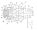
図1〜2は、本発明に関する参考例の形態の第1例を示している。本参考例の電気自動車用駆動装置は、電動モータ1aと、遊星歯車式変速機11と、回転伝達装置3aとを備える。このうちの電動モータ1aは、その出力軸により、この出力軸と同心に設けられた、前記遊星歯車式変速機11の駆動側回転軸4aを回転駆動する。
[First example of reference example ]
1 and 2 show a first example of a form of a reference example relating to the present invention. The electric vehicle drive device of this reference example includes an
又、この遊星歯車式変速機11は、前記電動モータ1aと前記回転伝達装置3aとの間に設置され、この電動モータ1aの動力を所定の変速比で変速してから、中空円管状の従動側回転軸5aを介し、前記回転伝達装置3aに伝達する。前記遊星歯車式変速機11は、前記電動モータ1aの出力軸と同心に配置された、前記駆動側回転軸4a及び前記従動側回転軸5aと、第一、第二両遊星歯車機構12、13と、リング歯車22と、第一、第二両制動装置14、15とから構成される。このうちの第一遊星歯車機構12は、第一太陽歯車16と、複数個(例えば3〜4個)の第一遊星歯車17、17と、キャリア18とにより構成している。前記各第一遊星歯車機構12は、このキャリア18に回転可能に支持された前記各第一遊星歯車17、17を、前記第一太陽歯車16に噛合させる、シングルピニオン式としている。この第一太陽歯車16は、前記駆動側回転軸4aの端部(図1の左端部)に設けられ、この駆動側回転軸4aにより回転駆動される。
The planetary
又、前記第二遊星歯車機構13は、第二太陽歯車19と、前記各第一遊星歯車17、17と同軸に設けられ、これら各第一遊星歯車17、17と同期して回転する各第二遊星歯車20、20と、これら各第二遊星歯車20、20と同数の第三遊星歯車21、21と、前記キャリア18とにより構成している。前記第二遊星歯車機構13は、このキャリア18に回転可能に支持されて対となる第二、第三各遊星歯車20、21を互いに噛合させると共に、このうちの内径寄りの各第三遊星歯車21、21を前記第二太陽歯車19に、それぞれ噛合させる、ダブルピニオン式としている。本参考例の場合、前記第一、第二各遊星歯車17、20のピッチ円直径及び歯数を同じとし、これら第一、第二各遊星歯車17、20を軸方向に連続して(一体に)設ける事で、所謂ロングピニオンギヤとしている。又、前記キャリア18は、前記従動側回転軸5aに動力を伝達する様に支持されている。
又、前記リング歯車22は、前記第二、第三各遊星歯車20、21のうちの、外径寄りの各第二遊星歯車20、20に噛合している。
The second
The
又、前記第一制動装置14は、前記リング歯車22と、変速機を収納したケース等の、固定の部分との間に設けられている。この様な第一制動装置14は、アクチュエータを制御して係合(断接)状態を切り換える事により、前記リング歯車22が固定の部分に対し回転が阻止される状態と、同じく許容される(空転する)状態とを切り換える。同様に、前記第二制御装置15は、前記第二太陽歯車19と前記固定の部分との間に設けられ、アクチュエータを制御して断接状態を切り換える事により、前記第二太陽歯車19が固定の部分に対し回転が阻止される状態と、同じく許容される(空転する)状態とを切り換える。尚、前記第一、第二両制動装置14、15のアクチュエータの構造は特に問わない。即ち、機械式のものを使用する事もできるし、油圧式や電磁式のものを使用しても良い。
The
又、前記回転伝達装置3aは、複数の歯車を組み合わせた、一般的な歯車伝達機構であり、前記遊星歯車式変速機11の従動側回転軸5aの回転をデファレンシャルギヤ8aの入力部に伝達し、このデファレンシャルギヤ8aの出力軸9c、9dにより、等速ジョイントを介して左右1対の駆動輪を回転駆動する様に構成している。
The
上述の様に構成する本参考例の電気自動車用駆動装置のうちの前記遊星歯車式変速機11は、前記第一、第二両制動装置14、15の断接状態を切り換える事で、前記駆動側回転軸4aと前記従動側回転軸5aとの間の減速比が大きい低速モード状態と、同じく減速比の小さい高速モード状態との何れか一方の状態で運転する。即ち、前記第一制動装置14を接続して前記リング歯車22の回転を阻止し、前記第二制動装置15を切断して前記第二太陽歯車19の回転を許容する(この第二太陽歯車19を空転させる)事で、前記低速モード状態を実現する。一方、前記第一制動装置14を切断して前記リング歯車22の回転を許容し(このリング歯車22を空転させ)、前記第二制動装置15を接続して前記第二太陽歯車19の回転を阻止する事で、前記高速モード状態を実現する。以下、それぞれの場合に就いて説明する。
The planetary
[第一制動装置14を接続し、第二制動装置15を切断する低速モード]
この低速モードでは、前記第一、第二両制動装置14、15のアクチュエータをそれぞれ制御する事で、図2の(A)に太線で示す様に、前記リング歯車22の回転を阻止し、前記第二太陽歯車19の回転を許容する。
この様な低速モード状態に於いて、前記電動モータ1aの動力は、次の(A)に示す経路を通って、前記従動側回転軸5aに伝達される。
(A) 電動モータ1a→駆動側回転軸4a→第一太陽歯車16→各第一遊星歯車17、17の自転運動→各第二遊星歯車20、20の自転運動→リング歯車22との噛合に基づく各第二遊星歯車20、20の公転運動→キャリア18→従動側回転軸5a
[Low speed mode in which the
In this low speed mode, by controlling the actuators of the first and
In such a low-speed mode state, the power of the
(A)
この様に、低速モード状態では、前記第一太陽歯車16を介して前記各第一遊星歯車17、17に伝達された電動モータ1aの動力が、前記リング歯車22との噛合に基づいて自転しつつ公転する、前記各第二遊星歯車20、20を介して、前記キャリア18に伝達される。この様に、低速モード状態では、ピッチ円直径が大きく、歯数の多いリング歯車22との噛合に基づいて自転しつつ公転する、前記各第二遊星歯車20、20を介して動力を伝達する事で、前記遊星歯車式変速機11の減速比を大きくする事ができる。
Thus, in the low speed mode state, the power of the
この様な、低速モード状態での減速比iLは、前記第一太陽歯車16の歯数をZ16、前記リング歯車22の歯数をZ22とした場合、次の(1)式で表わされる。

[第一制動装置14を切断し、第二制動装置15を接続する高速モード]
この高速モードでは、前記第一、第二両制動装置14、15のアクチュエータをそれぞれ制御する事で、図2の(B)に太線で示す様に、前記リング歯車22の回転を許容し、前記第二太陽歯車19の回転を阻止する。
この様な高速モード状態に於いて、前記電動モータ1aの動力は、次の(B)に示す経路を通って、前記従動側回転軸5aに伝達される。
(B) 電動モータ1a→駆動側回転軸4a→第一太陽歯車16→各第一遊星歯車17、17の自転運動→各第二遊星歯車20、20の自転運動→各第三遊星歯車21、21の自転運動→第二太陽歯車19との噛合に基づく各第三遊星歯車21、21の公転運動→キャリア18→従動側回転軸5a
[High-speed mode in which the
In this high speed mode, by controlling the actuators of the first and
In such a high-speed mode state, the power of the
(B)
この様に、高速モード状態では、前記第一太陽歯車16を介して前記各第一遊星歯車17、17に伝達された電動モータ1aの動力が、前記第二太陽歯車19との噛合に基づいて自転しつつ公転する、前記各第三遊星歯車21、21を介してキャリア18に伝達される。この様に、高速モード状態では、ピッチ円直径が小さく、歯数の少ない第二太陽歯車19との噛合に基づいて自転しつつ公転する、前記各第三遊星歯車21、21を介して動力を伝達する事で、前記遊星歯車式変速機11の減速比が小さくなる。
Thus, in the high speed mode state, the power of the
この様な、高速モード状態での減速比iHは、前記第二太陽歯車19の歯数をZ19とした場合、次の(2)式で表わされる。
ここで、本参考例の場合、前記低速モード状態と前記高速モード状態との間の段間比I(この低速モード状態に於ける減速比/この高速モード状態に於ける減速比)を、2若しくは2の近傍としている。低速モード状態に於ける減速比と、高速モード状態に於ける減速比とは、それぞれ前記(1)、(2)式で表わされるので、前記段間比Iは次の(3)式で表わされる。
上述の様に構成される本参考例の電気自動車用駆動装置によれば、この電気自動車用駆動装置を小型且つ簡易に構成できるので、充電1回当りの走行距離を長くし、電気自動車の利便性を向上させる事ができる。即ち、変速機構として前記遊星歯車式変速機11を用いており、動力を複数の遊星歯車17、20、21に分散して伝達する為、これら各遊星歯車17、20、21の1個当たりが伝達するトルクを低く抑えられる。又、前記第一太陽歯車16は前記各第一遊星歯車17、17と、前記リング歯車22は前記各第二遊星歯車20、20と、前記第二太陽歯車19は前記各第三遊星歯車21、21と、それぞれ複数箇所で噛合する事で動力を伝達する。従って、前記各歯車16、19、22の歯に必要とされる強度や剛性は、前述した従来構造の様に、1対の歯車10a、10c(10b、10d)の1箇所ずつ噛合により動力を伝達する場合と比較して低く抑えられる。この結果、一般的な歯車機構による変速機構を用いた場合と比較して、変速機構を小型・軽量化する事が可能となる。
According to the electric vehicle drive device of the present reference example configured as described above, the electric vehicle drive device can be configured in a small and simple manner, so that the travel distance per charge is increased and the convenience of the electric vehicle is increased. Can be improved. That is, the planetary
又、前記遊星歯車式変速機11は、減速比の異なる低速モードと高速モードとを、前記第一、第二両制動装置14、15を制御する(選択的に作動させる)事で、前記リング歯車22及び前記第二太陽歯車19の回転の可否を、それぞれ切り換える事により選択する。本参考例の場合、前記第一、第二両制動装置14、15は、前記両歯車19、22を、常に静止している(回転する事がない)部分に対する回転の可否を切り換えるものであり、前述した従来構造の様に、回転体同士(回転軸と歯車)の相対回転の可否を切り換える必要がない。この為、前記第一、第二両制動装置14、15の断接状態を切り換える為のアクチュエータとして油圧式の様に、小型でしかも大きな力を発生させられるものを使用できて、トルクの伝達容量を確保しつつ、前記遊星歯車式変速機11を組み込んだ電気自動車用駆動装置の構造の簡易化を図れる。
The planetary
又、前記各歯車16、19、22の歯数Z16、Z19、Z22を適切な値に規制する事で、前記低速モードと前記高速モードとの間の段間比を2若しくは2の近傍にできる。この結果、前記電動モータ1aを使用した電気自動車用駆動装置に於いて、一般的な変速機を搭載したガソリンエンジン車と同等の性能が得られ、車両の加速性能及び高速性能を改善できる。
Further, by controlling the number of teeth Z 16 , Z 19 , Z 22 of each gear 16 , 19 , 22 to an appropriate value, the step ratio between the low speed mode and the high speed mode is 2 or 2. Can be in the vicinity. As a result, in the electric vehicle drive device using the
[参考例の第2例]
図3は、本発明に関する参考例の第2例を示している。本参考例の電気自動車用駆動装置を構成する遊星歯車式変速機11aは、リング歯車22aを、シングルピニオン式である第一遊星歯車機構12aの第一遊星歯車17、17に噛合させている。
その他の部分の構成及び作用は、上述した参考例の第1例と同様であるから、同等部分には同一符号を付して、重複する説明は省略する。
[Second example of reference example ]
FIG. 3 shows a second example of a reference example relating to the present invention. In the planetary
Since the configuration and operation of the other parts are the same as those in the first example of the reference example described above, the same parts are denoted by the same reference numerals, and redundant description is omitted.
[参考例の第3例]
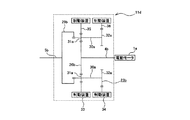
図4〜5は、本発明に関する参考例の第3例を示している。本参考例の場合、第一、第二両制動装置14a、15aの断接状態を切り換える為のアクチュエータ37a、37bを、それぞれ、サーボモータの回転駆動力を軸方向の推力に変換する電動式のものとしている。即ち、前記両アクチュエータ37a、37bは、図示しないサーボモータと、ピストン38と、ウォームホイール39とをそれぞれ備える。このうちのピストン38は、軸方向中間部の外周面を雄ねじ部40としたもので、遊星歯車式変速機11aを収納したケーシング内に、回転を阻止した状態で、軸方向の変位のみを可能に支持している。又、前記ウォームホイール39は、前記サーボモータの出力軸に支持固定されたウォームギヤ(図示省略)と噛合するもので、全体を円環状としており、前記ケーシング内に、軸方向の変位を阻止した状態で、回転のみ可能に支持している。又、前記ウォームホイール39の内周面に、前記雄ねじ部40と螺合する雌ねじ部41を設けている。尚、本参考例の場合、前記両アクチュエータ37a、37bを前記遊星歯車式変速機11aの軸方向中間部に設ける為、前記ピストン38を円筒状とし、内径側に、この遊星歯車式変速機11aを構成する各部材を配置している。但し、前記両アクチュエータ37a、37bの両方或いは何れか一方を、前記遊星歯車式変速機11aと軸方向に隣接する部分に設ける場合には、当該アクチュエータのピストンを円柱状とする事もできる。
[Third example of reference example ]
4 to 5 show a third example of the reference example related to the present invention. In the case of this reference example , the
上述の様に構成するアクチュエータ37a(37b)の作動時には、前記サーボモータの出力軸を所定方向に回転し、前記ウォームホイール39を回転駆動する。そして、前記雄ねじ部40と前記雌ねじ部41との螺合に基づいて、前記ピストン38の先端部により、リング歯車22aと同期した回転を可能に支持された第一回転部材42に設けられた、湿式多板クラッチを構成する回転側摩擦プレートである第一摩擦係合部43(又は、第二太陽歯車19と同期した回転を可能に支持された第二回転部材44に設けられた、湿式多板クラッチを構成する回転側摩擦プレートである第二摩擦係合部45)を、前記遊星歯車式変速機11aを収納したケーシング内に設けられて回転しない部分である、湿式多板クラッチを構成する非回転側摩擦プレートを設けた固定の部分46に向け(図4〜5の左方に)押し付ける。そして、前記第一摩擦係合部43(又は、前記第二摩擦係合部45)と、前記固定の部分46とを摩擦係合させて、前記リング歯車22a(又は、前記第二太陽歯車19)の回転を阻止する。これに対し、このリング歯車22a(又はこの第二太陽歯車19)の回転を許容する場合には、前記サーボモータの出力軸を前記所定方向とは逆方向に回転し、前記ピストン38を、このピストン38の先端部が前記第一摩擦係合部43(又は、前記第二摩擦係合部45)を、前記固定の部分46に向け押し付けている力を解除する方向(図4〜5の右方)に変位させる。この結果、前記リング歯車22a(又は、前記第二太陽歯車19)の回転が許容される。
When the
本参考例の電気自動車用駆動装置の場合、駆動側回転軸4aと従動側回転軸5aとの間の減速比の大きい低速モード状態で運転する場合には、図示しない制御装置により、図5の(A)に示す様に、前記両アクチュエータ37a、37bのうち一方のアクチュエータ37aのサーボモータを前記所定方向に回転して、前記リング歯車22aの前記固定の部分46に対する回転を阻止し、同じく他方のアクチュエータ37bのサーボモータを前記所定方向と反対方向に回転して、前記第二太陽歯車19の回転を許容する。これに対し、減速比の小さい高速モードで運転する場合には、前記制御装置により、同図の(B)に示す様に、前記一方のアクチュエータ37aのサーボモータを前記所定方向と反対方向に回転して、前記リング歯車22aの回転を許容し、前記他方のアクチュエータ37bのサーボモータを前記所定方向に回転して、前記第二太陽歯車19の回転を阻止する。
In the case of the electric vehicle drive device of this reference example , when operating in the low speed mode state in which the reduction ratio between the drive side
又、本参考例の場合、前記サーボモータの出力軸の回転を、この出力軸に支持固定されたウォームギヤと前記ウォームホイール39との噛合、及び、前記ピストン38の雄ねじ部40とこのウォームホイール39の雌ねじ部41との螺合に基づいて、このピストン38の軸方向の推力に変換する。そして、この軸方向の推力に基づきこのピストン38の先端面により前記第一摩擦係合部43(又は、前記第二摩擦係合部45)を、前記固定の部分46に向け押し付けて、これら第一摩擦係合部43(又は、第二摩擦係合部45)と固定の部分46とを摩擦係合させる。この状態で、前記ウォームギヤと前記ウォームホイール39との噛合、及び、前記雄ねじ部40と前記雌ねじ部41との螺合により、前記第一摩擦係合部43(又は、前記第二摩擦係合部45)が、前記固定の部分46に向け押し付けている力を解除する方向に変位するのを抑えられる。この為、前記第一摩擦係合部43(又は、前記第二摩擦係合部45)と前記固定の部分46とを摩擦係合した状態で、前記サーボモータに通電し続ける必要がなく、無駄な電力消費を防止できる。
Further, in the case of this reference example , the rotation of the output shaft of the servo motor is caused by meshing between the
尚、前記ウォームホイール39の回転を前記ピストン38の軸方向の推力に変換する為の構造として、前記雄ねじ部40と前記雌ねじ部41との螺合の代わりに、ボールねじ機構を採用する事もできる。即ち、ウォームホイールの内周面に断面形状が部分円弧形で螺旋状に形成した外径側ボールねじ溝と、ピストンの外周面に断面形状が部分円弧形で螺旋状に形成した内径側ボールねじ溝との間に複数個のボールを転動自在に設ける。ウォームギヤとウォームホイールとの噛合だけで摩擦係合部が、固定の部分に向け押し付けている力を解除する方向に変位するのを抑えられるのであれば、上述の様なボールねじ機構を採用する事により、前記雄ねじ部40と前記雌ねじ部41との螺合による場合と比較して、サーボモータの出力を小さく抑えられ、このサーボモータの消費電力の低減や小型化を図れる。
その他の部分の構成及び作用は、上述した参考例の第2例と同様であるから、同等部分には同一符号を付して、重複する説明は省略する。
As a structure for converting the rotation of the
Since the configuration and operation of the other parts are the same as those of the second example of the reference example described above, the same parts are denoted by the same reference numerals, and redundant description is omitted.
[実施の形態の第1例]
図6〜12は、請求項1〜2に対応する、本発明の実施の形態の第1例を示している。本例の場合、第一、第二両制動装置14b、15bの断接状態を、単一のアクチュエータ37cにより切り換える様に構成している。この為に、本例のアクチュエータ37cは、ピストン38aの軸方向中間部の外周面に雄ねじ部40aを設けている。そして、この雄ねじ部40aを、ウォームホイール39の内周面に設けた雌ねじ部41と螺合している。又、前記第一、第二両制動装置14b、15bを、前記アクチュエータ37cに関して互いに軸方向反対側に配置している(これら第一、第二両制動装置14b、15bを構成する第一、第二両摩擦係合部43、45が、前記ピストン38aの軸方向両端面にそれぞれ対向する様にしている)。
[ First example of embodiment]
6 to 12 show a first example of an embodiment of the present invention corresponding to claims 1 and 2 . In the case of this example, the first and
本例の電気自動車用駆動装置は、減速比の大きい低速モード状態で運転する場合には、図12の(A)に示す様に、サーボモータ47の出力軸を所定方向{同図の(A)の時計方向}に回転し、この出力軸に支持固定したウォームギヤ48との噛合に伴い前記ウォームホイール39を回転駆動する。すると、前記ピストン38aが、前記雄ねじ部40aと雌ねじ部41との螺合に基づいて変位し、このピストン38aの軸方向片端部{図12の(A)の右端部}が前記第一摩擦係合部43を固定の部分46に向けて押し付け、同じく軸方向他端部{同図の(A)の左端部}が前記第二摩擦係合部45を前記固定の部分46に向けて押し付ける力を解除する方向{同図の(A)の右方}に変位する。この結果、前記第一摩擦係合部43と前記固定の部分46とが摩擦係合してリング歯車22aの回転が阻止されると共に、第二太陽歯車19の回転が許容される。
When the driving apparatus for an electric vehicle of this example is operated in a low speed mode state with a large reduction ratio, as shown in FIG. 12A, the output shaft of the
これに対し、減速比の小さい高速モード状態で運転する場合には、図12の(B)に示す様に、前記サーボモータ47の出力軸を前記所定方向とは反対方向{同図の(B)の反時計方向}に回転し、前記ウォームホイール39を回転駆動する。すると、前記ピストン38aが、前記螺合に基づいて変位し、このピストン38aの軸方向片端部が前記第一摩擦係合部43を固定の部分46に向けて押し付ける力を解除し、同じく軸方向他端部が前記第二摩擦係合部45を前記固定の部分46に向けて押し付ける。この結果、これら第二摩擦係合部45と固定の部分46とが摩擦係合して前記第二太陽歯車19の回転が阻止されると共に、前記リング歯車22aの回転が許容される。
On the other hand, when operating in the high speed mode state with a small reduction ratio, as shown in FIG. 12B, the output shaft of the
上述の様な本例の電気自動車用駆動装置によれば、前記第一、第二両制動装置14b、15bの断接状態を、単一のアクチュエータ37cにより切り換える事ができる。この為、電気自動車用駆動装置を、前述した参考例の第3例の場合と比較して、更に小型且つ簡易に構成でき、電気自動車の利便性をより向上させる事ができる。
その他の部分の構成及び作用は、前述した参考例の第2〜3例と同様であるから、同等部分には同一符号を付して、重複する説明は省略する。
According to the electric vehicle driving apparatus of the present example as described above, the connection / disconnection state of the first and
Since the configuration and operation of the other parts are the same as those in the second to third examples of the reference example described above, the same parts are denoted by the same reference numerals, and redundant description is omitted.
[実施の形態の第2例]
図13〜15は、請求項1、3に対応する、本発明の実施の形態の第2例を示している。本例の場合も、上述した実施の形態の第1例の場合と同様に、第一、第二両制動装置14c、15cを単一のアクチュエータ37dにより切り換える様に構成している。本例のアクチュエータ37dは、図示しないサーボモータと、第一、第二両ピストン49、50と、ウォームホイール39aとを備える。このうちの第一、第二両ピストン49、50は、それぞれの軸方向基端部(図13〜15の左端部)の外周面を、互いにねじ切り方向を反対方向とした第一、第二両雄ねじ部51、52としている。又、前記ウォームホイール39aは、内周面を軸方向片半部(図13〜15の右半部)の大径部53と、軸方向他半部(図13〜15の左半部)の小径部54とを段部55により連続させた段付円筒面としている。そして、前記ウォームホイール39aの内周面のうち前記大径部53に前記第一雄ねじ部51と螺合する第一雌ねじ部56を、同じく小径部54に前記第二雄ねじ部52と螺合する第二雌ねじ部57を、それぞれ設けている。
[ Second Example of Embodiment]
13 to 15 show a second example of an embodiment of the present invention corresponding to claims 1 and 3 . Also in the case of this example, similarly to the case of the first example of the above-described embodiment, the first and
又、前記第一、第二両制動装置14c、15cを、前記アクチュエータ37dに対し軸方向に関して互いに同じ側に配置し、これら第一、第二両制動装置14c、15cを構成する第一、第二両摩擦係合部43、45が、前記第一、第二両ピストン49、50の先端面にそれぞれ対向する様に構成している。この為に、このうちの第一ピストン49を円筒状とし、内径側に前記第二ピストン50の軸方向中間部乃至先端部を挿通した状態で、前記第一雄ねじ部51を前記第一雌ねじ部56に螺合し支持している。
The first and
本例の電気自動車用駆動装置は、減速比の大きい低速モード状態で運転する場合には、図15の(A)に示す様に、前記サーボモータの出力軸を所定方向{同図の(A)の時計方向}に回転し、前記ウォームホイール39aを回転駆動する。すると、前記雄ねじ部51と前記第一雌ねじ部56との螺合に基づいて、前記第一ピストン49が変位し、この第一ピストン49の先端部{図15の(A)の右端部}が前記第一摩擦係合部43を、固定の部分46に向けて押し付ける{同図の(A)の右方に変位する}。一方、前記第二ピストン47は、前記第一雄ねじ部51と反対方向にねじ切られた前記第二雄ねじ部52と、前記第二雌ねじ部57との螺合に基づいて、この第二ピストン47の先端部が前記第二摩擦係合部45を前記固定の部分46に向けて押し付ける力を解除する方向{同図の(A)の左方}に変位する。この結果、図14〜15の(A)に示す様に、前記第一摩擦係合部43と前記固定の部分46とが摩擦係合してリング歯車22の回転が阻止されると共に、第二太陽歯車19の回転が許容される。
When the driving apparatus for an electric vehicle of this example is operated in a low speed mode state with a large reduction ratio, as shown in FIG. 15A, the output shaft of the servo motor is set in a predetermined direction {(A of FIG. ) In the clockwise direction} to rotationally drive the
これに対し、減速比の小さい高速モード状態で運転する場合には、図15の(B)に示す様に、前記サーボモータの出力軸を前記所定方向と反対方向{同図の(B)の反時計方向}に回転させ、前記ウォームホイール39aを回転駆動する。すると、前記雄ねじ部51と前記第一雌ねじ部56との螺合に基づいて、前記第一ピストン49が、この第一ピストン49の先端部が前記第一摩擦係合部43を前記固定の部分46に向けて押し付ける力を解除する方向{同図の(B)の左方}に変位する。一方、前記第二ピストン47は、前記第二雄ねじ部50と前記第二雌ねじ部57との螺合に基づいて、この第二ピストン47の先端部が前記第二摩擦係合部45を前記固定の部分46に向けて押し付ける{同図の(B)の右方に変位する}。この結果、図14〜15の(B)に示す様に、これら第二摩擦係合部45と固定の部分46とが摩擦係合して前記第二太陽歯車19の回転が阻止されると共に、前記リング歯車22の回転が許容される。
On the other hand, when operating in the high speed mode state with a small reduction ratio, as shown in FIG. 15 (B), the output shaft of the servo motor is set in the direction opposite to the predetermined direction {in FIG. Rotate counterclockwise} to drive the
本例の電気自動車用駆動装置の場合、前述した実施の形態の第1例の場合と同様に、前記第一、第二両制動装置14c、15cの断接状態を、単一のアクチュエータ37dにより切り換える事ができる為、電気自動車の利便性をより向上させる事ができる。
更に、本例の場合、前記第一、第二両制動装置14c、15cを、遊星歯車式変速機11を構成する第一、第二両遊星歯車機構12、13と軸方向に隣接する状態で配置している。そして、前記第一、第二両制動装置14c、15cは、前記両歯車22、19と同期して回転する第一、第二両回転部材42、44に設けた前記第一、第二両摩擦係合部43、45を、前記固定の部分46に対し軸方向に相対変位させる事で、前記両歯車22、19の回転の可否を切り換える様に構成している。この為、前記第一、第二両回転部材42、44を含め、前記第一、第二両制動装置14c、15cを構成する部材の寸法、形状及び配置を適切に規制すれば、これら両制動装置14c、15cの外径を、前記両遊星歯車機構12、13の外径以下に抑えられ、前記電動自動車用駆動装置のより一層の小型化を図れる。
その他の部分の構成及び作用は、前述した参考例の第1、3、及び、実施の形態の第1例と同様であるから、同等部分には同一符号を付して、重複する説明は省略する。
In the case of the electric vehicle drive device of this example, as in the case of the first example of the above-described embodiment, the connection state of the first and
Further, in this example, the first and
Since the configuration and operation of other parts are the same as those of the first and third examples of the reference example described above and the first example of the embodiment, the same parts are denoted by the same reference numerals, and redundant description is omitted. To do.
前述した図1に示す、本発明の電気自動車用駆動装置を構成する遊星歯車式変速機11の段間比Iに関して、具体的な値の1例を示す。
先ず、第一、第二両遊星歯車機構12、13を構成する各歯車16、17(、20)、19、21、22の歯数Z16、Z17(=Z20)、Z19、Z21、Z22に就いて、以下の様に規制する。
Z16=31
Z17=17
Z19=15
Z21=19
Z22=65
この条件下で、前述した(1)式〜(3)式より求められる、低速モードでの減速比iLと、高速モードでの減速比iHと、段間比Iとは、以下の通りとなる。
iL=0.323
iH=0.674
I=2.09
One example of specific values is shown for the interstage ratio I of the planetary
First, the number of teeth Z 16 , Z 17 (= Z 20 ), Z 19 , Z of the
Z 16 = 31
Z 17 = 17
Z 19 = 15
Z 21 = 19
Z 22 = 65
Under these conditions, the reduction ratio i L in the low speed mode, the reduction ratio i H in the high speed mode, and the interstage ratio I, which are obtained from the expressions (1) to (3) described above, are as follows. It becomes.
i L = 0.323
i H = 0.674
I = 2.09
本発明の電気自動車用駆動装置を実施する場合に、電動モータと、遊星歯車式変速機の駆動側入力軸との間に、例えば摩擦ローラ式減速機等の減速機を設けても良い。この様にすれば、効率の良い、小型且つ高回転型の電動モータを使用して、前記遊星歯車式変速機部分の運転速度を適正値にできる。又、前記第一、第二両制動装置のアクチュエータの構造は特に問わない。即ち、機械式のものを使用する事もできるし、油圧式や電磁式のものを使用しても良い。 When implementing the electric vehicle drive device of the present invention, a reduction gear such as a friction roller reduction gear may be provided between the electric motor and the drive-side input shaft of the planetary gear type transmission. In this way, the operation speed of the planetary gear transmission can be set to an appropriate value by using an efficient, small and high rotation type electric motor. Moreover, the structure of the actuators of the first and second braking devices is not particularly limited. That is, a mechanical type can be used, or a hydraulic type or an electromagnetic type can be used.
以下では、本発明と同様に、電気自動車用駆動装置の小型化を図る為、この電気自動車用駆動装置に組み込む変速機に遊星歯車機構を用いた、遊星歯車式変速機の具体例(本発明に関する参考例)に就いて説明する。
[本発明に関する参考例の第4例]
図16は、本発明に関する参考例の第4例を示している。本参考例は、遊星歯車式変速機11bを、電動モータ1aの出力軸により回転駆動される駆動側回転軸4bと、遊星歯車機構23と、従動側回転軸5bと、クラッチ機構24と、制動装置25とから構成している。この従動側回転軸5bは、前記駆動側回転軸4bと同心に設けられ、その回転を回転伝達装置3aに入力し、デファレンシャルギヤ8a(図1〜2参照)の入力部に伝達する様にしている。
Hereinafter, as in the present invention, in order to reduce the size of the electric vehicle drive device, a specific example of the planetary gear type transmission using the planetary gear mechanism in the transmission incorporated in the electric vehicle drive device (the present invention). Reference example) will be described.
[ Fourth example of a reference example related to the present invention]
FIG. 16 shows a fourth example of the reference example relating to the present invention. In this reference example, the planetary gear type transmission 11b is driven by a drive side
又、前記遊星歯車機構23は、太陽歯車26と、複数の遊星歯車27、27と、リング歯車28と、キャリア29とから構成される。前記遊星歯車機構23は、このキャリア29に回転可能に支持された前記各遊星歯車27、27を、前記太陽歯車26に噛合させると共に、前記リング歯車28にも噛合させるシングルピニオン式としている。前記太陽歯車26は、前記駆動側回転軸4bの軸方向中間部に設けられ、この駆動側回転軸4bにより回転駆動される。又、前記キャリア29は、前記従動側回転軸5bに動力を伝達する様に支持されている。
The planetary gear mechanism 23 includes a
又、前記クラッチ機構24は、前記駆動側回転軸4bと前記従動側回転軸5bとの間に設けられ、動力が伝達される状態と同じく伝達されない状態とを切り換え可能にしている。前記制動装置25は、前記リング歯車28とケース等の固定の部分との間に設けられ、このリング歯車28をこの固定の部分に対し回転が許容される状態と、同じく阻止される状態とを切り換え可能としている。
The
上述の様に構成される本参考例の遊星歯車式変速機11bは、前記クラッチ機構24と前記制動装置25との断接状態をそれぞれ切り換える事で、前記駆動側回転軸4bと前記従動側回転軸5bとの間の減速比が大きい低速モード状態と、同じく減速比の小さい高速モード状態との何れか一方の状態で運転する。即ち、前記クラッチ機構24を切断して前記駆動側回転軸4bと前記従動側回転軸5bとの間での直接の動力伝達を不能とし、前記制動装置25を接続して、前記固定の部分に対する前記リング歯車28の回転を阻止する事で、前記低速モードを実現する。
この低速モードに於ける前記遊星歯車式変速機11bの減速比iL1は、前記両歯車26、28の歯数をZ26、Z28とすると、次の(4)式の様に表わされる。
The reduction ratio i L1 of the planetary gear type transmission 11b in this low speed mode is expressed as the following equation (4), assuming that the number of teeth of both the gears 26 and 28 is Z 26 and Z 28 .
又、前記クラッチ機構24を接続して前記駆動側回転軸4bと前記従動側回転軸5bとの間での直接の動力伝達を可能とし、前記制動装置25を切断して前記固定の部分に対する前記リング歯車28の回転を許容する事で、前記高速モードを実現する。この高速モードに於ける前記遊星歯車式変速機11bの減速比iH1は1となる(減速されない)。
従って、前記低速モードと前記高速モードとの間の段間比I1は次の(5)式で表わされる。
Accordingly, the interstage ratio I 1 between the low speed mode and the high speed mode is expressed by the following equation (5).
[本発明に関する参考例の第5例]
図17は、本発明に関する参考例の第5例を示している。本参考例は、遊星歯車式変速機11cを、電動モータ1aと同心に設けられた駆動側回転軸4bと、遊星歯車機構23aと、従動側回転軸5bと、クラッチ機構24と、制動装置25aとから構成している。このうちの遊星歯車機構23aは、キャリア29aに回転可能に支持された、複数の遊星軸30、30の軸方向一端部(図17の左端部)にそれぞれ支持固定された第一遊星歯車31、31を太陽歯車26aに、同じく軸方向他端部(図17の右端部)にそれぞれ支持固定された第二遊星歯車32、32をリング歯車28aに、それぞれ噛合させている。
又、前記制動装置25aは、前記リング歯車28aと固定の部分との間に設けられ、このリング歯車28aをこの固定の部分に対し回転が許容される状態と、同じく阻止される状態とを切り換え可能としている。
[ Fifth Example of Reference Example Related to the Present Invention]
FIG. 17 shows a fifth example of the reference example relating to the present invention. In this reference example, the planetary
The
この様に構成される本参考例の遊星歯車式変速機11cは、上述した参考例の第1例と同様に、前記クラッチ機構24及び前記制動装置25aの断接状態を切り換える事により、減速比の大きい低速モードと、同じく小さい高速モードとを切り換える。この低速モードに於ける前記遊星歯車式変速機11cの減速比iL2は、前記各歯車26a、28a、31、32の歯数をZ26a、Z28a、Z31、Z32とすると、次の(6)式の様に表わされる。
この様な、段間比I2は、前記各歯数Z26a、Z28a、Z31、Z32を適切な値に規制して、2若しくは2の近傍とする事ができる為、前記遊星歯車式変速機11cを取り込んだ電気自動車用駆動装置に於いて、一般的な変速機を搭載したガソリンエンジン車と同等の性能が得られ、車両の加速性能及び高速性能の改善できる。但し、本参考例の場合も、上述した参考例の第1例と同様に、前記両回転軸4b、5b同士の間で動力を伝達する状態と伝達しない状態とを、これら両回転軸4b、5bが回転している状態のまま、切り換える為のクラッチ機構24が必要となり、構造が複雑になる可能性がある。
The interstage ratio I 2 can be set to 2 or 2 by restricting the number of teeth Z 26a , Z 28a , Z 31 , Z 32 to an appropriate value. In the electric vehicle drive device incorporating the
[本発明に関する参考例の第6例]
図18は、本発明に関する参考例の第6例を示している。本参考例は、遊星歯車式変速機11dを、駆動側回転軸4bと、遊星歯車機構23bと、従動側回転軸5bと、第一、第二両制動装置33、34とから構成している。このうちの遊星歯車機構23bは、キャリア29bに回転可能に支持された、複数の遊星軸30a、30aの軸方向中間部にそれぞれ支持固定した第一遊星歯車31a、31aを太陽歯車26bに噛合させると共に、第一リング歯車35にも噛合させている。又、前記各遊星軸30a、30aの端部(図18の右端部)にそれぞれ支持固定した第二遊星歯車32a、32aを第二リング歯車36に噛合させている。そして、これら第一、第二両リング歯車35、36を、前記両制動装置33、34により、固定の部分に対し回転を許容する状態と回転を阻止する状態とを、それぞれ切り換え可能としている。
[ Sixth Reference Example for the Present Invention]
FIG. 18 shows a sixth example of the reference example relating to the present invention. In this reference example, the planetary
上述の様に構成する本参考例の遊星歯車式変速機11dの場合、前記両制動装置33、34の断接状態を切り換える事により、減速比の異なる2つのモードを切り換える。即ち、前記第一制動装置33を接続して前記第一リング歯車35の回転を阻止し、前記第二制動装置34を切断して前記第二リング歯車36の回転を許容した第一のモードに於ける減速比iaは、次の(8)式で表わされる。
又、前記第一制動装置33を切断して前記第一リング歯車35の回転を許容し、前記第二制動装置34を接続して前記第二リング歯車36の回転を阻止した第二のモードに於ける減速比ibは、次の(9)式で表わされる。
ここで、前記第一遊星歯車31aの歯数Z31aが、前記第二遊星歯車32aの歯数Z32aよりも少ない(Z31a<Z32a)場合、前記第一のモードに於ける減速比iaが、前記第二のモードに於ける減速比ibよりも大きくなる(ia>ib)。又、前記第一、第二両リング歯車35、36の歯数Z35、Z36は、それぞれ次の(10)〜(11)の様に表わされる。
![]()
![]()
![]()
![]()
この様に表わされるIc1を、前記各歯車31a、32aの歯数Z31a、Z32aを適切に規制し、2若しくは2の近傍とする事は難しい。即ち、段間比Ic1を2若しくは2の近傍とするには、前記(12)式より、前記第一遊星歯車31aの歯数Z31aを0若しくは0の近傍としなければならない。実際には、この歯数Z31aを0若しくは0の近傍とする事は難しく、段間比Ic1を2若しくは2の近傍とする事は困難である。
従って、本参考例の遊星歯車式変速機11dを組み込んだ電気自動車用駆動装置に於いて、一般的な変速機を搭載したガソリンエンジン車と同等の性能が得る事での車両の加速性能及び高速性能の改善を図りづらい。
It is difficult to set I c1 expressed in this way to be close to 2 or 2 by appropriately regulating the number of teeth Z 31a and Z 32a of the
Therefore, in the electric vehicle drive device incorporating the planetary
一方、前記第一遊星歯車31aの歯数Z31aが、前記第二遊星歯車32aの歯数Z32aよりも多い(Z31a>Z32a)場合、前記第一のモードに於ける減速比iaが、前記第二のモードに於ける減速比ibよりも小さくなる(ia<ib)。従って、前記遊星歯車式変速機11dの段間比Ic2=(ib/ia)は、次の(13)式の様に表わされる。
この様に表わされる段間比Ic2を2若しくは2の近傍とするには、前記(13)式より、前記第一遊星歯車31aの歯数Z31aを、前記第二遊星歯車32aの歯数Z32aの3倍程度(Z31a≒3Z32a)としなければならない。前記歯数Z31aをこの歯数Z32aの3倍程度とすると、前記第一遊星歯車31a及び前記第一リング歯車35のピッチ円直径が大きくなり、前記遊星歯車式変速機11dが大型化してしまう可能性がある。
In order to set the interstage ratio I c2 expressed in this way to 2 or in the vicinity of 2, the number of teeth Z 31a of the first
1 電動モータ
2 変速装置
3、3a 回転伝達装置
4 駆動側回転軸
5 従動側回転軸
6a、6b 歯車伝達機構
7a、7b クラッチ機構
8、8a デファレンシャルギヤ
9a〜9d 出力軸
10a〜10d 歯車
11、11a〜11d 遊星歯車式変速機
12、12a 第一遊星歯車機構
13 第二遊星歯車機構
14、14a〜14c 第一制動装置
15、15a〜15c 第二制動装置
16 第一太陽歯車
17 第一遊星歯車
18 キャリア
19 第二太陽歯車
20 第二遊星歯車
21 第三遊星歯車
22、22a リング歯車
23、23a、23b 遊星歯車機構
24 クラッチ装置
25、25a 制動装置
26、26a、26b 太陽歯車
27 遊星歯車
28、28a リング歯車
29、29a、29b キャリア
30、30a 遊星軸
31、31a 第一遊星歯車
32、32a 第二遊星歯車
33 第一制動装置
34 第二制動装置
35 第一リング歯車
36 第二リング歯車
37a〜37d アクチュエータ
38、38a ピストン
39、39a ウォームホイール
40、40a 雄ねじ部
41 雌ねじ部
42 第一回転部材
43 第一摩擦係合部
44 第二回転部材
45 第二摩擦係合部
46 固定の部分
47 サーボモータ
48 ウォームギヤ
49 第一ピストン
50 第二ピストン
51 第一雄ねじ部
52 第二雄ねじ部
53 大径部
54 小径部
55 段部
56 第一雌ねじ部
57 第二雌ねじ部
DESCRIPTION OF SYMBOLS 1 Electric motor 2 Transmission device 3, 3a Rotation transmission device 4 Drive side rotation shaft 5 Drive side rotation shaft 6a, 6b Gear transmission mechanism 7a, 7b Clutch mechanism 8, 8a Differential gear 9a-9d Output shaft 10a-10d Gear 11, 11a -11d planetary gear type transmission 12, 12a first planetary gear mechanism 13 second planetary gear mechanism 14, 14a-14c first braking device 15, 15a-15c second braking device 16 first sun gear 17 first planetary gear 18 Carrier 19 Second sun gear 20 Second planetary gear 21 Third planetary gear 22, 22a Ring gear 23, 23a, 23b Planetary gear mechanism 24 Clutch device 25, 25a Braking device 26, 26a, 26b Sun gear 27 Planetary gear 28, 28a Ring gear 29, 29a, 29b Carrier 30, 30a Planetary shaft 31, 31a First planetary gear 32, 32a Second planetary gear 33 First brake device 34 Second brake device 35 First ring gear 36 Second ring gear 37a-37d Actuator 38, 38a Piston 39, 39a Worm wheel 40, 40a Male thread portion 41 Female screw portion 42 First rotating member 43 First friction engaging portion 44 Second rotating member 45 Second friction engaging portion 46 Fixed portion 47 Servo motor 48 Worm gear 49 First piston 50 Second piston 51 First male screw portion 52 First Double male thread part 53 Large diameter part 54 Small diameter part 55 Step part 56 First female thread part 57 Second female thread part
Claims (3)
前記遊星歯車式変速機は、前記駆動側回転軸と、前記従動側回転軸と、第一、第二両遊星歯車機構と、リング歯車と、第一、第二両制動装置とを組み合わせて成り、
このうちの前記第一遊星歯車機構は、第一太陽歯車と、複数個の第一遊星歯車と、キャリアとから構成され、このキャリアに回転可能に支持されたこれら各第一遊星歯車を、前記第一太陽歯車に噛合させるシングルピニオン式であり、この第一太陽歯車は、前記駆動側回転軸により回転駆動する状態で設けられており、
前記第二遊星歯車機構は、第二太陽歯車と、前記各第一遊星歯車と同軸に設けられ、これら各第一遊星歯車と同期して回転する複数個の第二遊星歯車と、これら各第二遊星歯車と同数の第三遊星歯車と、前記キャリアとから構成され、このキャリアに回転可能に支持されて対となる前記各第二、第三遊星歯車同士を互いに噛合させると共に、このうちの内径寄りの各第三遊星歯車を前記第二太陽歯車に噛合させるダブルピニオン式であり、前記キャリアにより前記従動側回転軸を回転駆動する様にしており、
前記リング歯車は、前記各第一遊星歯車若しくは前記各第二、第三遊星歯車のうちの外径寄りの各第二遊星歯車に噛合しており、
前記第一制動装置は前記リング歯車を、前記第二制動装置は前記第二太陽歯車を、固定の部分に対し回転が阻止される状態と、同じく回転が許容される状態とにそれぞれ切り換えるものであり、減速比の大きい低速モード状態では、前記第一制動装置を作動させる事により前記リング歯車が前記固定の部分に対して回転するのを阻止すると共に、前記第二制動装置を非作動とする事により前記第二太陽歯車がこの固定の部分に対して回転するのを許容し、減速比の小さい高速モード状態では、前記第一制動装置を非作動とする事により前記リング歯車が前記固定の部分に対して回転するのを許容すると共に、前記第二制動装置を作動させる事により前記第二太陽歯車がこの固定の部分に対して回転するのを阻止しており、
前記第一、第二両制動装置の作動状態を切り換える為のアクチュエータが、サーボモータの回転駆動力を軸方向の推力に変換し、この軸方向の推力に基づいて前記固定の部分と相手部材の摩擦係合部とを互いに近付く方向に軸方向に相対変位させ、この相手部材を前記固定の部分を押し付ける事により、これら固定の部分と相手部材とを摩擦係合するものであり、
単一のアクチュエータにより前記第一、第二両制動装置の作動状態を切り換える為に、前記サーボモータを所定方向に回転させた場合に、前記リング歯車又はこのリング歯車と同期して回転する部分に設けた第一摩擦係合部と、前記固定の部分とを互いに近付く方向に相対変位させ、この第一摩擦係合部をこの固定の部分に向け押し付けて摩擦係合させる事により、前記リング歯車がこの固定の部分に対し回転するのを阻止し、前記第二太陽歯車又はこの第二太陽歯車と同期して回転する部分に設けた第二摩擦係合部と、前記固定の部分とを互いに離隔する方向に軸方向に相対変位させ、この第二摩擦係合部をこの固定の部分に向けて押し付ける力を解除する事で、前記第二太陽歯車がこの固定の部分に対し回転するのを許容し、前記サーボモータを前記所定方向と反対方向に回転させた場合に、前記第一摩擦係合部と前記固定の部分とを互いに離隔する方向に軸方向に相対変位させ、この第一摩擦係合部をこの固定の部分に向けて押し付ける力を解除する事で、前記リング歯車がこの固定の部分に対し回転するのを許容し、前記第二摩擦係合部と前記固定の部分とを互いに近付く方向に軸方向に相対変位させ、この第二摩擦係合部をこの固定の部分に向け押し付けて摩擦係合させる事により、前記第二太陽歯車がこの固定の部分に対し回転するのを阻止する事を特徴とする電気自動車用駆動装置。 An electric motor, a planetary gear type transmission having a drive side rotation shaft that is driven to rotate by an output shaft of the electric motor, and rotation of a driven side rotation shaft of the planetary gear type transmission to a pair of left and right drive wheels In a drive device for an electric vehicle provided with a rotation transmission device for transmission,
The planetary gear type transmission is a combination of the driving side rotating shaft, the driven side rotating shaft, first and second planetary gear mechanisms, a ring gear, and both first and second braking devices. ,
Of these, the first planetary gear mechanism is composed of a first sun gear, a plurality of first planetary gears, and a carrier, and each of the first planetary gears rotatably supported by the carrier, It is a single pinion type that meshes with the first sun gear, and this first sun gear is provided in a state of being rotationally driven by the drive side rotating shaft,
The second planetary gear mechanism includes a second sun gear, a plurality of second planetary gears that are provided coaxially with the first planetary gears, and that rotate in synchronization with the first planetary gears. The second planetary gear is composed of the same number of third planetary gears as the two planetary gears, and the carrier, and the second and third planetary gears that are paired by being rotatably supported by the carrier are engaged with each other. It is a double pinion type in which each third planetary gear close to the inner diameter meshes with the second sun gear, and the driven rotation shaft is driven to rotate by the carrier,
The ring gear meshes with each of the first planetary gears or each of the second planetary gears near the outer diameter of the second and third planetary gears,
The first braking device switches the ring gear, and the second braking device switches the second sun gear between a state where rotation is prevented with respect to a fixed portion and a state where rotation is allowed. Yes, in the low speed mode state with a large reduction ratio, operating the first braking device prevents the ring gear from rotating with respect to the fixed portion, and deactivates the second braking device. This allows the second sun gear to rotate with respect to this fixed portion, and in the high speed mode state with a small reduction ratio, the ring gear is fixed by deactivating the first braking device. Allowing the second sun gear to rotate relative to the fixed part by allowing the second braking device to operate and allowing the part to rotate relative to the part ;
An actuator for switching the operating states of the first and second braking devices converts the rotational driving force of the servo motor into axial thrust, and based on this axial thrust, the fixed portion and the mating member The friction engagement portion is relatively displaced in the axial direction in a direction approaching each other, and the mating member is pressed against the fixing portion, whereby the fixing portion and the mating member are frictionally engaged.
When the servo motor is rotated in a predetermined direction in order to switch the operating state of the first and second braking devices by a single actuator, the ring gear or a portion that rotates in synchronization with the ring gear The ring gear is provided by relatively displacing the provided first friction engagement portion and the fixed portion toward each other, and pressing the first friction engagement portion toward the fixed portion for friction engagement. Is prevented from rotating with respect to the fixed portion, and the second sun gear or the second friction engagement portion provided on the portion rotating in synchronization with the second sun gear and the fixed portion are mutually connected. Relative displacement in the axial direction in the direction of separation and releasing the force that presses the second frictional engagement part toward the fixed part allows the second sun gear to rotate relative to the fixed part. Allow the servo When the motor is rotated in a direction opposite to the predetermined direction, the first friction engagement portion and the fixed portion are relatively displaced in an axial direction in a direction away from each other, and the first friction engagement portion is By releasing the pressing force toward the fixed portion, the ring gear is allowed to rotate with respect to the fixed portion, and the second frictional engagement portion and the fixed portion are moved toward each other. It is possible to prevent the second sun gear from rotating with respect to the fixed portion by relatively displacing it in the axial direction and pressing the second friction engagement portion against the fixed portion to cause frictional engagement. A drive device for an electric vehicle.
このうちのピストンは、軸方向中間部の外周面を雄ねじ部としたもので、前記遊星歯車式変速機を納めるケーシング内に、回転を阻止された状態で軸方向の変位を可能に設けられており、
前記ウォームホイールは、全体を円筒状とし、内周面に前記雄ねじ部と螺合する雌ねじ部を設けており、
前記第一、第二両制動装置を、前記ピストンに関して互いに軸方向反対側に配置しており、前記サーボモータを所定方向に回転させた場合に、前記ピストンが、このピストンの軸方向片端部により前記第一摩擦係合部を前記固定の部分に向けて押し付ける方向に変位し、前記サーボモータを前記所定方向と反対方向に回転させた場合に、前記ピストンが、このピストンの軸方向他端部により前記第二摩擦係合部を前記固定の部分に向けて押し付ける方向に変位するものである、請求項1に記載の電気自動車用駆動装置。 The actuator includes a piston and a worm wheel meshing with a worm gear supported and fixed to an output shaft of the servo motor;
Of these pistons, the outer peripheral surface of the intermediate portion in the axial direction is a male threaded portion, and is provided in the casing in which the planetary gear type transmission is housed so as to be capable of axial displacement while being prevented from rotating. And
The worm wheel has a cylindrical shape as a whole, and is provided with an internal thread portion that engages with the external thread portion on an inner peripheral surface,
The first and second braking devices are arranged opposite to each other in the axial direction with respect to the piston, and when the servo motor is rotated in a predetermined direction, the piston is moved by one axial end of the piston. When the first friction engagement portion is displaced in the direction of pressing toward the fixed portion and the servo motor is rotated in a direction opposite to the predetermined direction, the piston is moved to the other axial end portion of the piston. The electric vehicle drive device according to claim 1 , wherein the second friction engagement portion is displaced in a direction of pressing the second friction engagement portion toward the fixed portion.
このうちの第一、第二両ピストンは、それぞれの軸方向基端部の外周面を、互いにねじ切り方向を互いに反対方向とした第一、第二両雄ねじ部としたもので、前記遊星歯車式変速機を納めるケーシング内に、回転を阻止された状態で軸方向の変位を可能にそれぞれ設けられており、
前記ウォームホイールは、内周面を軸方向片半部の大径部と軸方向他半部の小径部とを段部により連続させた段付円筒面としており、前記内周面のうちの大径部に前記第一雄ねじ部と螺合する第一雌ねじ部を、同じく小径部に前記第二雄ねじ部と螺合する第二雌ねじ部を、それぞれ設けており、
前記第一、第二両制動装置を、前記第一、第二両ピストンに対し互いに軸方向に関して同じ側に配置しており、前記サーボモータを所定方向に回転させた場合に、前記第一ピストンが、この第一ピストンの軸方向先端部により前記第一摩擦係合部を前記固定の部分に向けて押し付ける方向に変位し、前記第二ピストンが、この第二ピストンの先端部により前記第二摩擦係合部を前記固定の部分に向けて押し付ける力を解除する方向に変位し、前記サーボモータの出力軸を前記所定方向と反対方向に回転させた場合に、前記第一ピストンが、この第一ピストンの軸方向先端部により前記第一摩擦係合部を前記固定の部分に向けて押し付ける力を解除する方向に変位し、前記第二ピストンが、この第二ピストンの先端部により前記第二摩擦係合部を前記固定の部分に向けて押し付ける方向に変位するものである、請求項1に記載の電気自動車用駆動装置。 The actuator includes both first and second pistons, and a worm wheel meshing with a worm gear supported and fixed to the output shaft of the servo motor.
Of these, the first and second pistons are the first and second male threaded portions whose outer circumferential surfaces of the axial base end portions are mutually opposite in threading direction. In the casing that houses the transmission, each is provided with axial displacement while being prevented from rotating,
In the worm wheel, the inner peripheral surface is a stepped cylindrical surface in which a large-diameter portion of one half of the axial direction and a small-diameter portion of the other half of the axial direction are continuous by a stepped portion. A first female threaded portion that engages with the first male threaded portion at the diameter portion, and a second female threaded portion that is threadedly engaged with the second male threaded portion at the smaller diameter portion, respectively,
The first and second braking devices are arranged on the same side in the axial direction with respect to the first and second pistons, and when the servo motor is rotated in a predetermined direction, the first piston Is displaced in a direction in which the first friction engagement portion is pressed toward the fixed portion by the axial front end portion of the first piston, and the second piston is displaced by the second piston end portion by the second piston. When the output force of the servo motor is rotated in the direction opposite to the predetermined direction when the friction engagement portion is displaced in a direction to release the force pressing the friction engagement portion toward the fixed portion, the first piston is moved to the first piston. The first piston is displaced in a direction to release the force pressing the first friction engagement portion toward the fixed portion by the tip of the second piston, and the second piston is moved by the tip of the second piston. Friction engagement part It is intended to be displaced in the direction of pressing toward the portion of the fixed, electric vehicle drive device according to claim 1.
Priority Applications (5)
| Application Number | Priority Date | Filing Date | Title |
|---|---|---|---|
| JP2012224983A JP6028507B2 (en) | 2011-10-28 | 2012-10-10 | Electric vehicle drive |
| US14/354,765 US9067491B2 (en) | 2011-10-28 | 2012-10-24 | Drive apparatus for an electric automobile |
| PCT/JP2012/077516 WO2013062017A1 (en) | 2011-10-28 | 2012-10-24 | Electric vehicle driving device |
| EP12843885.0A EP2772665B1 (en) | 2011-10-28 | 2012-10-24 | Electric vehicle driving device |
| CN201280053031.2A CN103917803A (en) | 2011-10-28 | 2012-10-24 | Electric vehicle driving device |
Applications Claiming Priority (3)
| Application Number | Priority Date | Filing Date | Title |
|---|---|---|---|
| JP2011236658 | 2011-10-28 | ||
| JP2011236658 | 2011-10-28 | ||
| JP2012224983A JP6028507B2 (en) | 2011-10-28 | 2012-10-10 | Electric vehicle drive |
Publications (3)
| Publication Number | Publication Date |
|---|---|
| JP2013108619A JP2013108619A (en) | 2013-06-06 |
| JP2013108619A5 JP2013108619A5 (en) | 2015-07-16 |
| JP6028507B2 true JP6028507B2 (en) | 2016-11-16 |
Family
ID=48167844
Family Applications (1)
| Application Number | Title | Priority Date | Filing Date |
|---|---|---|---|
| JP2012224983A Expired - Fee Related JP6028507B2 (en) | 2011-10-28 | 2012-10-10 | Electric vehicle drive |
Country Status (5)
| Country | Link |
|---|---|
| US (1) | US9067491B2 (en) |
| EP (1) | EP2772665B1 (en) |
| JP (1) | JP6028507B2 (en) |
| CN (1) | CN103917803A (en) |
| WO (1) | WO2013062017A1 (en) |
Cited By (1)
| Publication number | Priority date | Publication date | Assignee | Title |
|---|---|---|---|---|
| WO2022176579A1 (en) | 2021-02-18 | 2022-08-25 | ユニプレス株式会社 | Two-step transmission for electric automobile |
Families Citing this family (24)
| Publication number | Priority date | Publication date | Assignee | Title |
|---|---|---|---|---|
| DE102015103584A1 (en) | 2015-03-11 | 2016-09-15 | Gkn Driveline International Gmbh | Gear arrangement and electric drive with such a gear arrangement |
| DE102015217521A1 (en) * | 2015-09-14 | 2017-03-16 | Siemens Aktiengesellschaft | Drive device for a motor vehicle, in particular an electric or hybrid vehicle |
| JP6533517B2 (en) * | 2015-09-29 | 2019-06-19 | 日鍛バルブ株式会社 | Torque transmission device |
| US9719584B1 (en) * | 2016-05-25 | 2017-08-01 | Guangzhou Sunmile Dynamic Technologies Corp., Ltd | Two-speed transaxle for electric vehicle |
| JP6418218B2 (en) * | 2016-10-06 | 2018-11-07 | トヨタ自動車株式会社 | Differential limiting device for vehicle |
| DE102017004932A1 (en) * | 2016-12-21 | 2018-06-21 | Daimler Ag | Transmission device for a motor vehicle |
| CN107061642A (en) * | 2017-03-15 | 2017-08-18 | 清华大学 | A kind of two grades of gearboxes of dual brake formula electric car and its control method |
| KR101909108B1 (en) * | 2017-04-04 | 2018-12-10 | 주식회사 인팩 | Multistage Reduction Drive System |
| DE102017007081B4 (en) * | 2017-07-27 | 2019-06-06 | Daimler Ag | Electric axle drive device for a motor vehicle, in particular for a commercial vehicle, and motor vehicle with at least one such electric axle drive device |
| CN109795310B (en) * | 2017-11-17 | 2023-08-11 | 宇通客车股份有限公司 | Hybrid power system and vehicle using same |
| DE102018211672A1 (en) | 2018-07-12 | 2020-01-16 | Robert Bosch Gmbh | Power shift multi-speed transmission |
| KR102532314B1 (en) * | 2018-07-30 | 2023-05-16 | 현대자동차주식회사 | Transmission for electric vehicle |
| CN108953539A (en) * | 2018-09-05 | 2018-12-07 | 恒大法拉第未来智能汽车(广东)有限公司 | Two speed transmission and electric car |
| CN108843751B (en) * | 2018-09-19 | 2019-09-06 | 吉林大学 | A kind of integration power drive system and its control method |
| CN111376714B (en) * | 2018-12-29 | 2022-04-15 | 比亚迪股份有限公司 | Electrically-driven speed reducer, electrically-driven axle power assembly and vehicle |
| CN111376713B (en) * | 2018-12-29 | 2021-07-20 | 比亚迪股份有限公司 | Electrically-driven speed reducer, electrically-driven axle power assembly and vehicle |
| CN109780146A (en) * | 2019-03-13 | 2019-05-21 | 重庆德音科技有限公司 | Two gears automatic speed changer for machine for electric vehicle |
| CN110065387A (en) * | 2019-04-26 | 2019-07-30 | 湖北启源科技有限公司 | A kind of electric piston drive type electric vehicle and its working method |
| WO2020263553A1 (en) * | 2019-06-28 | 2020-12-30 | Horton, Inc. | Transmission system with planetary gearing operable in forward and reverse modes |
| CN112829739B (en) * | 2019-11-22 | 2023-04-07 | 广州汽车集团股份有限公司 | Method for controlling operating mode of hybrid drive device and hybrid system |
| DE102020112624A1 (en) | 2020-05-11 | 2021-11-11 | Schaeffler Technologies AG & Co. KG | Transmission device for an electric drive of a vehicle |
| CN113266672A (en) * | 2021-05-06 | 2021-08-17 | 恒大新能源汽车投资控股集团有限公司 | Gear shifting reminding method and system and vehicle |
| CN113236731B (en) * | 2021-05-10 | 2023-01-06 | 柳工柳州传动件有限公司 | Planetary gearbox and electric engineering machinery |
| WO2023048134A1 (en) * | 2021-09-24 | 2023-03-30 | 株式会社アイシン | Vehicle drive device |
Family Cites Families (17)
| Publication number | Priority date | Publication date | Assignee | Title |
|---|---|---|---|---|
| JPS608548A (en) | 1983-06-25 | 1985-01-17 | Mazda Motor Corp | Speed changing device of automatic speed changer |
| JPS608548U (en) * | 1983-06-29 | 1985-01-21 | トヨタ自動車株式会社 | Electric vehicle transmission |
| US4966267A (en) * | 1989-09-21 | 1990-10-30 | Borg-Warner Automotive Diversified Transmission Products Corporation | Ball screw actuated clutch combination |
| US5517876A (en) * | 1994-08-04 | 1996-05-21 | Eaton Corporation | Transmission spring loaded shift device |
| JP2004249943A (en) * | 2003-02-21 | 2004-09-09 | Toyota Motor Corp | Driving device for vehicle |
| JP2005090682A (en) * | 2003-09-19 | 2005-04-07 | Suzuki Motor Corp | Automatic transmission |
| JP2005180507A (en) * | 2003-12-17 | 2005-07-07 | Nsk Ltd | Actuator for automatic transmission |
| JP2006022879A (en) | 2004-07-07 | 2006-01-26 | Gkn ドライブライン トルクテクノロジー株式会社 | Electric motor drive mechanism |
| JP2009002499A (en) * | 2007-06-25 | 2009-01-08 | Bunji Koshiishi | Planetary gear type automobile starting device using torque for actuating supercharger |
| JP2009250375A (en) * | 2008-04-08 | 2009-10-29 | Toyota Motor Corp | Vehicle drive |
| WO2010041531A1 (en) * | 2008-10-06 | 2010-04-15 | Ntn株式会社 | Electric motor driving device |
| JP5568229B2 (en) | 2008-10-06 | 2014-08-06 | Ntn株式会社 | Electric motor drive device |
| JP2010223298A (en) | 2009-03-23 | 2010-10-07 | Ntn Corp | Electric motor driving device |
| JP5413719B2 (en) * | 2009-07-31 | 2014-02-12 | 日立オートモティブシステムズ株式会社 | Electric brake device |
| JP5051476B2 (en) * | 2009-08-10 | 2012-10-17 | アイシン・エィ・ダブリュ株式会社 | Vehicle drive device |
| JP2011208681A (en) * | 2010-03-29 | 2011-10-20 | Jatco Ltd | Vehicular reduction gear |
| CN103814237B (en) * | 2011-09-26 | 2016-05-18 | 日本精工株式会社 | Electric automobile-use drive unit |
-
2012
- 2012-10-10 JP JP2012224983A patent/JP6028507B2/en not_active Expired - Fee Related
- 2012-10-24 CN CN201280053031.2A patent/CN103917803A/en active Pending
- 2012-10-24 WO PCT/JP2012/077516 patent/WO2013062017A1/en active Application Filing
- 2012-10-24 US US14/354,765 patent/US9067491B2/en not_active Expired - Fee Related
- 2012-10-24 EP EP12843885.0A patent/EP2772665B1/en not_active Not-in-force
Cited By (2)
| Publication number | Priority date | Publication date | Assignee | Title |
|---|---|---|---|---|
| WO2022176579A1 (en) | 2021-02-18 | 2022-08-25 | ユニプレス株式会社 | Two-step transmission for electric automobile |
| US11933398B2 (en) | 2021-02-18 | 2024-03-19 | Unipres Corporation | Two-speed transmission apparatus for electric vehicle |
Also Published As
| Publication number | Publication date |
|---|---|
| EP2772665A1 (en) | 2014-09-03 |
| JP2013108619A (en) | 2013-06-06 |
| WO2013062017A1 (en) | 2013-05-02 |
| EP2772665A4 (en) | 2016-10-26 |
| US9067491B2 (en) | 2015-06-30 |
| US20140287863A1 (en) | 2014-09-25 |
| EP2772665B1 (en) | 2018-12-05 |
| CN103917803A (en) | 2014-07-09 |
Similar Documents
| Publication | Publication Date | Title |
|---|---|---|
| JP6028507B2 (en) | Electric vehicle drive | |
| JP2013108619A5 (en) | ||
| JP4763044B2 (en) | Transmission having a countershaft separable in a direct gear | |
| JP4274268B2 (en) | Power transmission device | |
| KR101575272B1 (en) | Transmission system of hybrid electric vehicle | |
| US9366321B2 (en) | Planetary gear transmission and electric vehicle | |
| JP5842998B2 (en) | Vehicle transmission | |
| JP5733410B2 (en) | Electric vehicle drive | |
| KR20020070482A (en) | Transmission devices, for ground vehicles and more particularly for motors-cars | |
| EP2855182A1 (en) | Two-speed transmission and electric vehicle | |
| JPWO2012026181A1 (en) | Vehicle engine starting device | |
| CN110131327B (en) | Spiral actuator of automobile clutch | |
| JP2013044406A (en) | Electric transmission and drive device for electric vehicle | |
| JP2023041927A (en) | Power transmission path switching device | |
| US20210222757A1 (en) | Power transmission unit | |
| CN110296194B (en) | Planetary three-gear shifting device | |
| JP7428171B2 (en) | power transmission device | |
| JP6802725B2 (en) | Vehicle oil pump drive | |
| JP2009001120A (en) | Power transmission device | |
| CN205859060U (en) | A kind of automotive transmission | |
| JP2009051262A (en) | Power output device | |
| JP7166735B2 (en) | vehicle transmission | |
| WO2014091770A1 (en) | Interrupting device and power transmission device provided with said interrupting device | |
| JP4894698B2 (en) | Continuously variable transmission | |
| CN105840758A (en) | Continuously variable device |
Legal Events
| Date | Code | Title | Description |
|---|---|---|---|
| A521 | Request for written amendment filed |
Free format text: JAPANESE INTERMEDIATE CODE: A523 Effective date: 20150527 |
|
| A621 | Written request for application examination |
Free format text: JAPANESE INTERMEDIATE CODE: A621 Effective date: 20150527 |
|
| A131 | Notification of reasons for refusal |
Free format text: JAPANESE INTERMEDIATE CODE: A131 Effective date: 20160223 |
|
| A521 | Request for written amendment filed |
Free format text: JAPANESE INTERMEDIATE CODE: A523 Effective date: 20160422 |
|
| TRDD | Decision of grant or rejection written | ||
| A01 | Written decision to grant a patent or to grant a registration (utility model) |
Free format text: JAPANESE INTERMEDIATE CODE: A01 Effective date: 20160920 |
|
| A61 | First payment of annual fees (during grant procedure) |
Free format text: JAPANESE INTERMEDIATE CODE: A61 Effective date: 20161003 |
|
| R150 | Certificate of patent or registration of utility model |
Ref document number: 6028507 Country of ref document: JP Free format text: JAPANESE INTERMEDIATE CODE: R150 |
|
| LAPS | Cancellation because of no payment of annual fees |