「第1実施形態」
本発明に係る第1実施形態を図1〜図7を参照して以下に説明する。第1実施形態のディスクブレーキは、二輪車や四輪車等の車両用、具体的には自動二輪車用のディスクブレーキである。
“First Embodiment”
A first embodiment according to the present invention will be described below with reference to FIGS. The disc brake of the first embodiment is a disc brake for vehicles such as two-wheeled vehicles and four-wheeled vehicles, specifically for motorcycles.
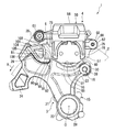
図1〜図4に示すように、このディスクブレーキ1は、ディスク2と、ディスク2の軸線方向の一側に配置されるキャリア3と、ディスク2を跨ぐようにキャリア3に支持されるキャリパ4とを有している。また、このディスクブレーキ1は、図3,図4に示すように二枚の摩擦パッド5,6を有しており、伸縮自在のブーツ12,13を有している。なお、図1,図2,図4,図5に示す矢印Rは、車両の前進時のディスク2の回転方向を示しており、この回転方向における入口側(図1,図4の左側、図2,図5の右側)をディスク回入側、出口側をディスク回出側として以下説明を行う。また、ディスク2の軸線方向をディスク軸方向、ディスク2の径方向をディスク径方向、ディスク2の回転方向をディスク回転方向とする。
As shown in FIGS. 1 to 4, the disc brake 1 includes a disc 2, a carrier 3 disposed on one side in the axial direction of the disc 2, and a caliper 4 supported by the carrier 3 so as to straddle the disc 2. And have. The disc brake 1 has two friction pads 5 and 6 as shown in FIGS. 3 and 4 and has elastic boots 12 and 13. 1, 2, 4, and 5 indicate the rotation direction of the disk 2 when the vehicle moves forward, and the entrance side in this rotation direction (the left side of FIGS. 1 and 4, FIG. 5). 2, the right side of FIG. 5) will be described below as the disk inlet side and the outlet side as the disk outlet side. The axial direction of the disk 2 is the disk axial direction, the radial direction of the disk 2 is the disk radial direction, and the rotational direction of the disk 2 is the rotational direction of the disk.
ディスク2は円板状をなしており、ディスクブレーキ1の制動対象である車両の図示略の車輪に設けられて、車輪の中心軸線と同心の回転中心軸線Oを中心に車輪と一体に回転する。
The disc 2 has a disc shape and is provided on a wheel (not shown) of a vehicle that is the subject of braking of the disc brake 1 and rotates integrally with the wheel about a rotation center axis O that is concentric with the center axis of the wheel. .
キャリア3は、車両の非回転部に固定されるもので、図1に示すように、ブラケット15と、いずれもブラケット15に一体的に固定されるスライドピン16,17とを有している。スライドピン16,17はキャリパ4のディスク軸方向の移動を案内するものである。
The carrier 3 is fixed to a non-rotating portion of the vehicle, and includes a bracket 15 and slide pins 16 and 17 that are fixed to the bracket 15 integrally as shown in FIG. The slide pins 16 and 17 guide the movement of the caliper 4 in the disk axis direction.
ブラケット15は、本実施形態においては、アルミニウム合金で一体成形されており、図3に示すように、主としてディスク2の一面側であるアウタ側(図3の右側であって車輪とは反対側)に配置されて、車両のディスク2の近傍の非回転部に固定されるものである。なお、ブラケット15の材質は、アルミニウム合金に限らず、鋳鉄等を用いて形成してもよい。
In this embodiment, the bracket 15 is integrally formed of an aluminum alloy, and as shown in FIG. 3, the outer side that is mainly one side of the disk 2 (the right side in FIG. 3 and the side opposite to the wheels). And is fixed to a non-rotating portion in the vicinity of the disk 2 of the vehicle. The material of the bracket 15 is not limited to an aluminum alloy, and may be formed using cast iron or the like.
ブラケット15は、図5および図6にも示すように、基板部21と、基板部21の長さ方向の一側の幅方向の一側に形成されたボス部22と、基板部21の長さ方向のボス部22と同側であって幅方向のボス部22とは反対側に形成された腕部23とを有している。また、ブラケット15は、基板部21の長さ方向のボス部22とは反対側であって幅方向のボス部22と同側に形成された係止部24と、基板部21の長さ方向の係止部24と同側であって幅方向の係止部24とは反対側に形成された腕部25とを有している。さらに、ブラケット15は、腕部25の腕部23側の近接位置にあって基板部21の厚さ方向一側に突出するパッド支持部(支持部)26を有している。
As shown in FIGS. 5 and 6, the bracket 15 includes a substrate portion 21, a boss portion 22 formed on one side in the width direction on the one side in the length direction of the substrate portion 21, and the length of the substrate portion 21. It has an arm portion 23 formed on the same side as the boss portion 22 in the vertical direction and on the opposite side of the boss portion 22 in the width direction. The bracket 15 includes a locking portion 24 formed on the opposite side to the boss portion 22 in the length direction of the substrate portion 21 and on the same side as the boss portion 22 in the width direction, and the length direction of the substrate portion 21. The arm portion 25 is formed on the same side as the locking portion 24 and on the opposite side of the locking portion 24 in the width direction. Further, the bracket 15 has a pad support portion (support portion) 26 that is located close to the arm portion 23 side of the arm portion 25 and protrudes to one side in the thickness direction of the substrate portion 21.
基板部21、ボス部22、腕部23、係止部24および腕部25は、ディスク2のアウタ側に配置され、パッド支持部26は、図4に示すようにディスク2のインナ側(図4の上側)まで延出している。パッド支持部26には、そのディスク軸方向の中間位置に、ディスク2を配置するための図示略の配置溝がディスク径方向に沿って内側から形成されており、よって、パッド支持部26は、ディスク2を跨ぐように配置される。
The board portion 21, the boss portion 22, the arm portion 23, the locking portion 24, and the arm portion 25 are disposed on the outer side of the disc 2, and the pad support portion 26 is disposed on the inner side of the disc 2 (see FIG. 4). (Upper side of 4). An unillustrated arrangement groove for arranging the disk 2 is formed in the pad support portion 26 at an intermediate position in the disk axial direction from the inside along the disk radial direction. It is arranged so as to straddle the disk 2.
図5に示すように、ブラケット15のボス部22には、基板部21の厚さ方向に沿って貫通穴28が形成されている。ブラケット15は、この貫通穴28内に図示略の車軸が配置され、腕部23がディスク径方向の中間位置にてディスク回入側かつディスク径方向外側に斜めに延出し、腕部25がディスク径方向外端位置にてディスク回入側かつディスク径方向外側に斜めに延出する状態で、車両の非回転部に取り付けられる。
As shown in FIG. 5, a through hole 28 is formed in the boss portion 22 of the bracket 15 along the thickness direction of the substrate portion 21. The bracket 15 has an axle (not shown) disposed in the through hole 28, the arm portion 23 extends obliquely to the disc insertion side and the disc radial direction outer side at an intermediate position in the disc radial direction, and the arm portion 25 is a disc. It is attached to the non-rotating part of the vehicle in a state where it extends obliquely toward the disk entry side and the disk radial direction outside at the radially outer end position.
図6にも示すように、ブラケット15には、腕部23の延出先端に内側ピン取付孔30が貫通穴28と平行に形成されており、腕部25の延出先端に外側ピン取付孔31が貫通穴28と平行に形成されている。内側ピン取付孔30には、内周部にメネジ32が形成されており、外側ピン取付孔31にも、内周部にメネジ33が形成されている。
As shown in FIG. 6, the bracket 15 has an inner pin mounting hole 30 formed in parallel with the through hole 28 at the extended tip of the arm portion 23, and an outer pin mounting hole at the extended tip of the arm portion 25. 31 is formed in parallel with the through hole 28. A female screw 32 is formed in the inner peripheral portion of the inner pin mounting hole 30, and a female screw 33 is formed in the inner peripheral portion of the outer pin mounting hole 31.
図3に示すように、スライドピン16は、ボルト部材36とカラー37とからなっている。ボルト部材36は、工具が係合可能な六角柱形状の頭部38と軸部39とを有している。軸部39は、頭部38とは反対側の所定範囲の外周部にオネジ40が形成されており、このオネジ40を除く部分が円柱状の嵌合部41となっている。カラー37は、円筒状をなしていて、ボルト部材36の嵌合部41を嵌合させることになり、この嵌合部41を覆うことになる。
As shown in FIG. 3, the slide pin 16 includes a bolt member 36 and a collar 37. The bolt member 36 has a hexagonal column-shaped head portion 38 and a shaft portion 39 with which a tool can be engaged. The shaft portion 39 has a male screw 40 formed on the outer peripheral portion of a predetermined range opposite to the head portion 38, and a portion excluding the male screw 40 is a cylindrical fitting portion 41. The collar 37 has a cylindrical shape, and the fitting portion 41 of the bolt member 36 is fitted therein, and the fitting portion 41 is covered.
ボルト部材36は、カラー37に嵌合部41を嵌合させた状態で、ブラケット15の内側ピン取付孔30のメネジ32にオネジ40において螺合されることになる。このようにネジ止めされたボルト部材36は、その頭部38がブラケット15とでカラー37を挟持することになり、その結果、カラー37とともにブラケット15に固定される。ボルト部材36およびカラー37からなるスライドピン16は、このようにしてブラケット15に取り付けられることになり、この状態で、全体的に、ディスク軸方向に沿う姿勢でブラケット15からディスク2とは反対側(アウタ側)に延出する。スライドピン16は、カラー37がブーツ13内に嵌合されており、カラー37の外周面がブーツ13で覆われている。スライドピン16は、このブーツ13を介してキャリパ4をディスク軸方向に移動可能に支持する。
The bolt member 36 is screwed to the female screw 32 of the inner pin mounting hole 30 of the bracket 15 at the male screw 40 in a state where the fitting portion 41 is fitted to the collar 37. The bolt member 36 screwed in this way has its head 38 sandwiching the collar 37 with the bracket 15, and as a result, is fixed to the bracket 15 together with the collar 37. The slide pin 16 composed of the bolt member 36 and the collar 37 is attached to the bracket 15 in this way, and in this state, the bracket 15 and the disk 2 are opposite to the disk 2 in a posture along the disk axial direction as a whole. Extend to (outer side). The slide pin 16 has a collar 37 fitted in the boot 13, and the outer peripheral surface of the collar 37 is covered with the boot 13. The slide pin 16 supports the caliper 4 through the boot 13 so as to be movable in the disk axial direction.
図4に示すように、スライドピン17は、工具が係合可能な六角柱形状の頭部43と軸部44とを有している。軸部44には、頭部43側の所定範囲の外周部にオネジ45が形成されており、このオネジ45を除く部分が円柱状のガイド部46となっている。スライドピン17は、ブラケット15の外側ピン取付孔31のメネジ33にオネジ45において螺合されることになり、ガイド部46においてキャリパ4をディスク軸方向に移動可能に支持する。
As shown in FIG. 4, the slide pin 17 has a hexagonal column-shaped head portion 43 and a shaft portion 44 with which a tool can be engaged. The shaft portion 44 is formed with a male screw 45 on an outer peripheral portion in a predetermined range on the head 43 side, and a portion excluding the male screw 45 is a cylindrical guide portion 46. The slide pin 17 is screwed into the female screw 33 of the outer pin mounting hole 31 of the bracket 15 at the male screw 45, and supports the caliper 4 so as to be movable in the disk axis direction at the guide portion 46.
キャリパ4は、図4に示すスライドピン17のガイド部46と、図3に示すスライドピン16のカラー37とで、ディスク軸方向に摺動可能となるようにキャリア3に支持されており、いわゆるピンスライド型のキャリパとなっている。キャリパ4は、図1に示すように、キャリパボディ50とピストン51とパッドピン52とを有している。
The caliper 4 is supported on the carrier 3 by a guide portion 46 of the slide pin 17 shown in FIG. 4 and a collar 37 of the slide pin 16 shown in FIG. It is a pin slide type caliper. As shown in FIG. 1, the caliper 4 includes a caliper body 50, a piston 51, and a pad pin 52.
キャリパボディ50は、アルミニウム合金等から鋳造により一体成形された後、切削加工されることで形成される。キャリパボディ50は、図3,図4に示すようにディスク2を跨いだ状態で、キャリア3の図4に示すスライドピン17のガイド部46および図3に示すスライドピン16に摺動可能に取り付けられている。キャリパボディ50は、ディスク2のアウタ側に配置されるシリンダ部55と、シリンダ部55のディスク径方向外側からディスク2の径方向外側を越えるようにインナ側に延出するブリッジ部56と、ブリッジ部56のインナ側の端部からシリンダ部55に対向するようにディスク径方向内側に延出する爪部57とを有している。
The caliper body 50 is formed by being integrally formed by casting from an aluminum alloy or the like and then being cut. The caliper body 50 is slidably attached to the guide portion 46 of the slide pin 17 shown in FIG. 4 of the carrier 3 and the slide pin 16 shown in FIG. 3 while straddling the disk 2 as shown in FIGS. It has been. The caliper body 50 includes a cylinder part 55 disposed on the outer side of the disk 2, a bridge part 56 extending from the outer side of the cylinder part 55 in the disk radial direction to the inner side of the disk 2, and a bridge It has a claw portion 57 that extends inward in the disk radial direction so as to face the cylinder portion 55 from the inner end portion of the portion 56.
図1に示すように、キャリパボディ50には、シリンダ部55のディスク回転方向の中間位置からディスク径方向内方かつディスク回入側に斜めに突出するようにして摺動案内部60が形成されており、また、ブリッジ部56からディスク回出側に突出するようにして摺動案内部61が形成されている。図3に示すように、摺動案内部60には、ブーツ保持穴62がディスク軸方向に貫通して形成されている。このブーツ保持穴62には、ブーツ13が嵌合されており、摺動案内部60は、このブーツ13とともにスライドピン16のカラー37に摺動可能に支持される。図4に示すように、摺動案内部61には、ディスク軸方向のシリンダ部55側からディスク軸方向の途中位置までピン摺接穴63が形成されている。このピン摺接穴63には、スライドピン17のガイド部46が嵌合されており、摺動案内部61は、このガイド部46に摺動可能に支持される。
As shown in FIG. 1, the caliper body 50 is formed with a sliding guide portion 60 so as to project obliquely from the intermediate position of the cylinder portion 55 in the disk rotation direction inward in the disk radial direction and toward the disk insertion side. In addition, a sliding guide portion 61 is formed so as to protrude from the bridge portion 56 to the disk delivery side. As shown in FIG. 3, a boot holding hole 62 is formed in the sliding guide portion 60 so as to penetrate in the disk axial direction. The boot 13 is fitted in the boot holding hole 62, and the sliding guide portion 60 is slidably supported on the collar 37 of the slide pin 16 together with the boot 13. As shown in FIG. 4, a pin sliding contact hole 63 is formed in the sliding guide portion 61 from the cylinder portion 55 side in the disc axial direction to an intermediate position in the disc axial direction. The guide portion 46 of the slide pin 17 is fitted in the pin sliding contact hole 63, and the sliding guide portion 61 is slidably supported by the guide portion 46.
ブーツ12は、ゴム製であり、スライドピン17のガイド部46のキャリア3とキャリパ4との間部分を覆う。ブーツ12は、キャリパ4の摺動案内部61のスライドピン17に対する移動時に伸縮するように蛇腹状をなしており、一端部がキャリパ4の摺動案内部61に係止され、他端部がキャリア3の腕部25に係止されている。
The boot 12 is made of rubber and covers a portion between the carrier 3 and the caliper 4 of the guide portion 46 of the slide pin 17. The boot 12 has a bellows shape so as to expand and contract when the slide guide portion 61 of the caliper 4 moves relative to the slide pin 17, and one end portion is locked to the slide guide portion 61 of the caliper 4, and the other end portion is Locked to the arm 25 of the carrier 3.
図3に示すブーツ13も、ゴム製であり、スライドピン16のカラー37を覆う。ブーツ13は、円筒状の中間部分が、摺動案内部60とともにカラー37上を摺動するように摺動案内部60のブーツ保持穴62内に嵌合されており、その両側部分が伸縮可能に蛇腹状をなしている。ブーツ13は、一端部がスライドピン16のカラー37の一端側の外周部に係止され、他端部がカラー37の他端側の外周部に係止されている。
The boot 13 shown in FIG. 3 is also made of rubber and covers the collar 37 of the slide pin 16. The boot 13 is fitted in the boot holding hole 62 of the sliding guide portion 60 so that the cylindrical intermediate portion slides on the collar 37 together with the sliding guide portion 60, and both side portions thereof can be expanded and contracted. It has a bellows shape. One end of the boot 13 is locked to the outer peripheral portion on one end side of the collar 37 of the slide pin 16, and the other end is locked to the outer peripheral portion on the other end side of the collar 37.
シリンダ部55には、図1に示すように有底のボア65が形成されている。ボア65は、図2に示す爪部57側に向かって開口するようにディスク軸方向に沿って形成されており、図1に示すピストン51は、シリンダ部55のボア65に摺動可能に嵌合されている。
As shown in FIG. 1, a bottomed bore 65 is formed in the cylinder portion 55. The bore 65 is formed along the disk axial direction so as to open toward the claw portion 57 shown in FIG. 2, and the piston 51 shown in FIG. 1 is slidably fitted into the bore 65 of the cylinder portion 55. Are combined.
図3および図4に示すように、シリンダ部55のディスク径方向外側かつディスク回入側には、ディスク回入側に突出する突出部67が形成されており、爪部57のディスク回入側にも、ディスク回入側に突出する突出部68が形成されている。
As shown in FIGS. 3 and 4, a projecting portion 67 that protrudes toward the disk insertion side is formed on the disk radial direction outside of the cylinder portion 55 and on the disk insertion side. In addition, a projecting portion 68 projecting to the disk entry side is formed.
図4に示すように、パッドピン52は、キャリパボディ50の突出部67に形成されたディスク軸方向に延びる貫通孔69および突出部68に形成されたディスク軸方向に延びる貫通孔70に嵌合されるものであり、この嵌合状態で突出部67および突出部68を結ぶように延在している。パッドピン52は、ディスク軸方向に沿っており、ディスク2よりもディスク径方向外側かつブリッジ部56および爪部57よりもディスク回入側において、ディスク2を跨ぐように配置されている。
As shown in FIG. 4, the pad pin 52 is fitted into a through hole 69 formed in the protrusion 67 of the caliper body 50 extending in the disk axial direction and a through hole 70 formed in the protrusion 68 extending in the disk axial direction. In this fitted state, the protrusion 67 and the protrusion 68 are connected to each other. The pad pin 52 extends along the disk axial direction, and is disposed so as to straddle the disk 2 on the disk radial direction outside of the disk 2 and on the disk insertion side of the bridge part 56 and the claw part 57.
図3に示すように、摩擦パッド5は、ディスク2の一面とピストン51およびシリンダ部55との間に配置されるアウタ側の摩擦パッドであり、摩擦パッド6は、ディスク2の他面と爪部57との間に配置されるインナ側の摩擦パッドである。摩擦パッド5,6は、同形状の図1および図2に示す裏板75と、裏板75に貼付される同形状の図3に示す摩擦材76とからなっており、裏板75に対する摩擦材76の貼付面が表裏逆向きになっている。つまり、摩擦パッド5,6は、鏡面対称形状をなしている。
As shown in FIG. 3, the friction pad 5 is an outer friction pad disposed between one surface of the disk 2 and the piston 51 and the cylinder portion 55, and the friction pad 6 is formed between the other surface of the disk 2 and the claw. It is an inner friction pad arranged between the portion 57. The friction pads 5, 6 are composed of the back plate 75 shown in FIGS. 1 and 2 having the same shape and the friction material 76 shown in FIG. 3 attached to the back plate 75. The sticking surface of the material 76 is reverse. That is, the friction pads 5 and 6 have a mirror symmetrical shape.
摩擦パッド5,6は、摩擦材76においてディスク2に当接することになり、図5に摩擦パッド6を示すように、摩擦材76の中心(重心、図心)を通り、摩擦材76の厚さ方向に沿う軸線が押圧中心軸線Xとなる。なお、摩擦材76の押圧中心軸線Xは、ディスク軸方向に沿うことになり、図1に示すピストン51の中心軸線と一致するように配置される。ここでは、ピストン51が一つであるため、摩擦材76の押圧中心軸線Xがピストン51の中心軸線と一致するように配置されることになるが、ピストン51がディスク回転方向に間隔をあけて複数設けられる場合、すべてのピストンの中心軸線の中心が摩擦材76の押圧中心軸線Xと一致するように配置される。
The friction pads 5 and 6 come into contact with the disk 2 in the friction material 76 and pass through the center (center of gravity, centroid) of the friction material 76 as shown in FIG. The axis along the vertical direction is the pressing center axis X. The pressing center axis X of the friction material 76 is along the disk axis direction, and is arranged so as to coincide with the center axis of the piston 51 shown in FIG. Here, since there is one piston 51, the pressing center axis X of the friction material 76 is arranged so as to coincide with the center axis of the piston 51. However, the piston 51 is spaced in the disk rotation direction. When a plurality of pistons are provided, they are arranged so that the centers of the center axes of all the pistons coincide with the pressing center axis X of the friction material 76.
裏板75は、一枚の板材から形成されるもので、図7に示すように、摩擦材76が貼付される主板部78と、主板部78の長さ方向一側の幅方向一側から斜め外方に延出する腕部79と、主板部78の長さ方向中間部の幅方向一側から幅方向に沿って外方に突出する突起部80と、主板部78の長さ方向他側に形成されたキャリア当接部(当接部)81とを有している。腕部79には、裏板75の厚さ方向に沿って貫通孔82が形成されている。
The back plate 75 is formed from a single plate material. As shown in FIG. 7, the main plate portion 78 to which the friction material 76 is attached and the width direction one side of the main plate portion 78 in the length direction are provided. An arm 79 extending obliquely outward, a protrusion 80 projecting outward along the width direction from one side in the width direction of the middle portion of the main plate portion 78, the length direction of the main plate portion 78, and the like And a carrier contact portion (contact portion) 81 formed on the side. A through hole 82 is formed in the arm portion 79 along the thickness direction of the back plate 75.
図3に示すように、アウタ側の摩擦パッド5は、摩擦材76をディスク2側に裏板75をシリンダ部55側に配置した状態とされ、この状態で、裏板75の貫通孔82にキャリパ4のパッドピン52を挿通させ、図1に示すように裏板75のディスク回出側の端部のキャリア当接部81においてキャリア3のパッド支持部26に当接する。これにより、摩擦パッド5は、図3に示す腕部79がパッドピン52に、図1に示すキャリア当接部81がパッド支持部26に、それぞれディスク軸方向に摺動可能に支持される。
As shown in FIG. 3, the friction pad 5 on the outer side is in a state in which the friction material 76 is disposed on the disk 2 side and the back plate 75 is disposed on the cylinder portion 55 side. The pad pin 52 of the caliper 4 is inserted, and as shown in FIG. Thus, the friction pad 5 is supported by the arm portion 79 shown in FIG. 3 on the pad pin 52 and the carrier contact portion 81 shown in FIG.
図3に示すように、インナ側の摩擦パッド6は、摩擦材76をディスク2側に裏板75を爪部57側に配置した状態とされ、この状態で、摩擦パッド5と同様に、裏板75の貫通孔82にキャリパ4のパッドピン52を挿通させ、図2に示すように裏板75のディスク回出側の端部のキャリア当接部81においてキャリア3のパッド支持部26に当接する。これにより、摩擦パッド6も、図3に示す腕部79がパッドピン52に、図2に示すキャリア当接部81がパッド支持部26に、それぞれディスク軸方向に摺動可能に支持される。
As shown in FIG. 3, the friction pad 6 on the inner side is in a state in which the friction material 76 is disposed on the disk 2 side and the back plate 75 is disposed on the claw part 57 side. The pad pin 52 of the caliper 4 is inserted through the through hole 82 of the plate 75, and contacts the pad support portion 26 of the carrier 3 at the carrier contact portion 81 at the end of the back plate 75 on the disk delivery side as shown in FIG. . As a result, the friction pad 6 is also supported by the arm portion 79 shown in FIG. 3 on the pad pin 52 and the carrier contact portion 81 shown in FIG.
キャリパ4は、図1に示すシリンダ部55のボア65にブレーキ液が導入されると、図3に示すピストン51がシリンダ部55に対しディスク軸方向に沿ってディスク2の方向に前進しアウタ側の摩擦パッド5をディスク2に向けて押圧することになる。すると、摩擦パッド5がディスク2の一面に摩擦材76において当接する。また、これにより生じる反力で、キャリパ4は、摺動案内部60においてブーツ13とともにキャリア3のスライドピン16上を摺動し、図4に示す摺動案内部61においてピン摺接穴63に嵌合されたスライドピン17上を摺動して、シリンダ部55をディスク2から離間させる方向に移動する。すると、爪部57が他方の摩擦パッド6の摩擦材76をディスク2の他面に当接させる。このようにして、キャリパ4は、爪部57とピストン51とによって摩擦パッド5,6を両側から挟んでディスク2に押圧することにより、ディスク2つまり車輪の回転にブレーキをかける。
When the brake fluid is introduced into the bore 65 of the cylinder portion 55 shown in FIG. 1, the caliper 4 moves forward in the direction of the disc 2 along the disc axial direction with respect to the cylinder portion 55 and moves toward the outer side. The friction pad 5 is pressed toward the disk 2. Then, the friction pad 5 comes into contact with one surface of the disk 2 at the friction material 76. Further, the caliper 4 slides on the slide pin 16 of the carrier 3 together with the boot 13 in the sliding guide portion 60 by the reaction force generated by this, and in the sliding guide portion 61 shown in FIG. It slides on the fitted slide pin 17 and moves in a direction in which the cylinder portion 55 is separated from the disk 2. Then, the claw portion 57 brings the friction material 76 of the other friction pad 6 into contact with the other surface of the disk 2. Thus, the caliper 4 brakes the rotation of the disk 2, that is, the wheel by pressing the friction pads 5 and 6 against the disk 2 from both sides by the claw portion 57 and the piston 51.
以上により、摩擦パッド5,6は、ディスク2の両面側に配置され、キャリア3のブラケット15のディスク回出側のパッド支持部26とキャリパ4のディスク回入側のパッドピン52とに摺動可能に支持されて、キャリパ4によりディスク2に押圧される。
As described above, the friction pads 5 and 6 are arranged on both sides of the disk 2 and can slide on the pad support part 26 on the disk delivery side of the bracket 15 of the carrier 3 and the pad pin 52 on the disk delivery side of the caliper 4. To the disc 2 by the caliper 4.
本実施形態において、図5に示すように、ブラケット15のパッド支持部26には、ディスク径方向内側にあってディスク回転方向(具体的にはディスク回入側)に向く面部90と、ディスク径方向外側にあってディスク回転方向(具体的にはディスク回入側)に向く面部91と、ディスク径方向外端部にあって、ディスク径方向外方に向く面部92とを有している。面部90,91は隣り合っており、面部91,92も隣り合っている。
In the present embodiment, as shown in FIG. 5, the pad support portion 26 of the bracket 15 includes a surface portion 90 that is on the inner side in the disk radial direction and faces the disk rotation direction (specifically, the disk insertion side), and the disk diameter. It has a surface portion 91 that is on the outer side in the direction and faces the disc rotation direction (specifically, the disc insertion side), and a surface portion 92 that is on the outer end portion in the disc radial direction and faces outward in the disc radial direction. The surface portions 90 and 91 are adjacent to each other, and the surface portions 91 and 92 are also adjacent to each other.
面部90は、ディスク軸方向に平行をなしており、ディスク2の回転中心軸線Oと摩擦材76の押圧中心軸線Xとを通りディスク径方向に延在する基準ディスク径方向線Yに対して、ディスク径方向外側ほど基準ディスク径方向線Y側に位置するように傾いている。言い換えれば、面部90は、ディスク2の回転中心軸線Oと摩擦材76の押圧中心軸線Xとを含む基準平面に平行な面を、ディスク軸方向に平行な状態を維持しつつディスク径方向外側ほど基準平面側に位置するように傾斜させた平面となっている。
The surface portion 90 is parallel to the disc axial direction, and with respect to a reference disc radial direction line Y extending in the disc radial direction through the rotation center axis O of the disc 2 and the pressing center axis X of the friction material 76. The outer side in the disk radial direction is inclined so as to be positioned on the reference disk radial direction line Y side. In other words, the surface portion 90 is a surface parallel to a reference plane including the rotation center axis O of the disk 2 and the pressing center axis X of the friction material 76, while maintaining a state parallel to the disk axis direction toward the outer side in the disk radial direction. The plane is inclined so as to be located on the reference plane side.
面部91は、ディスク軸方向に平行をなしており、基準ディスク径方向線Yに対して、ディスク径方向外側ほど基準ディスク径方向線Yとは反対側に位置するように傾いている。言い換えれば、面部91は、ディスク2の回転中心軸線Oと摩擦材76の押圧中心軸線Xとを含む基準平面に平行な面を、ディスク軸方向に平行な状態を維持しつつディスク径方向外側ほど基準平面とは反対側に位置するように傾斜させた平面となっている。
The surface portion 91 is parallel to the disc axial direction, and is inclined with respect to the reference disc radial direction line Y so as to be located on the opposite side of the reference disc radial direction line Y toward the disc radial direction outer side. In other words, the surface portion 91 has a surface parallel to the reference plane including the rotation center axis O of the disk 2 and the pressing center axis X of the friction material 76, while maintaining a state parallel to the disk axis direction toward the outer side in the disk radial direction. The plane is inclined so as to be located on the side opposite to the reference plane.
面部90,91の上記形状により、パッド支持部26の面部90,91で形成される部位がディスク回転方向の押圧中心軸線X側に向けて先細の凸形状をなす凸状部94となっている。なお、面部90,91のなす角度は鈍角であり、面部90の基準ディスク径方向線Yとのなす角度α1と面部91の基準ディスク径方向線Yとのなす角度α2とは同じとなっている。
Due to the shape of the surface portions 90 and 91, the portion formed by the surface portions 90 and 91 of the pad support portion 26 is a convex portion 94 that forms a tapered convex shape toward the pressing center axis X side in the disk rotation direction. . The angle formed by the surface portions 90 and 91 is an obtuse angle, and the angle α1 formed by the reference disk radial direction line Y of the surface portion 90 and the angle α2 formed by the reference disk radial direction line Y of the surface portion 91 are the same. .
摩擦材76の押圧中心軸線Xは、基準ディスク径方向線Yの延在方向において、パッド支持部26の面部90,91の範囲内に配置されている。より具体的に、摩擦材76の押圧中心軸線Xは、基準ディスク径方向線Yの延在方向における位置を、面部90,91の交差部つまり凸状部94の頂部95と一致させている。
The pressing center axis X of the friction material 76 is disposed within the range of the surface portions 90 and 91 of the pad support portion 26 in the extending direction of the reference disk radial direction line Y. More specifically, the pressing center axis X of the friction material 76 matches the position of the reference disk radial direction line Y in the extending direction with the intersecting portion of the surface portions 90 and 91, that is, the top portion 95 of the convex portion 94.
面部92は、ディスク軸方向に平行をなしており、基準ディスク径方向線Yに対して直交する平面内に配置されている。面部91,92は、鈍角をなして交差している。
The surface portion 92 is parallel to the disk axial direction and is disposed in a plane perpendicular to the reference disk radial direction line Y. The surface portions 91 and 92 intersect at an obtuse angle.
以上により、2つの面部90,91は、基準ディスク径方向線Yに対して傾いている。また、摩擦材76の押圧中心軸線Xが、基準ディスク径方向線Yの延在方向におけるパッド支持部26の面部90,91の範囲内に存在しており、具体的に、基準ディスク径方向線Yの延在方向の位置を、面部90,91の交わる交点(頂部95)と一致させている。また、2つの面部90,91は、基準ディスク径方向線Yとのなす角度α1,α2が略同角度となっている。さらに、パッド支持部26の2つの面部90,91で形成される部位が、摩擦材76の押圧中心軸線Xに向かう凸形状となっている。
As described above, the two surface portions 90 and 91 are inclined with respect to the reference disk radial direction line Y. Further, the pressing center axis X of the friction material 76 exists within the range of the surface portions 90 and 91 of the pad support portion 26 in the extending direction of the reference disk radial direction line Y. Specifically, the reference disk radial direction line The position of Y in the extending direction is made to coincide with the intersection (top 95) where the surface portions 90 and 91 intersect. Further, the angles α1 and α2 formed between the two surface portions 90 and 91 and the reference disk radial direction line Y are substantially the same angle. Further, a portion formed by the two surface portions 90 and 91 of the pad support portion 26 has a convex shape toward the pressing center axis X of the friction material 76.
上記したキャリア3のパッド支持部26の形状に合うように、裏板75のキャリア当接部81が形成されている。キャリア当接部81には、ディスク径方向内側にあってディスク回転方向(具体的にはディスク回出側)に向く面部100と、ディスク径方向外側にあってディスク回転方向(具体的にはディスク回出側)に向く面部101と、ディスク径方向外端部にあって、ディスク径方向内方に向く面部102とを有している。面部100,101は隣り合っており、面部101,102も隣り合っている。
A carrier contact portion 81 of the back plate 75 is formed so as to match the shape of the pad support portion 26 of the carrier 3 described above. The carrier abutting portion 81 has a surface portion 100 on the inner side in the disk radial direction and facing the disk rotation direction (specifically, the disk delivery side), and on the outer side in the disk radial direction and specifically in the disk rotation direction (specifically, the disk And a surface portion 102 at the outer end in the disk radial direction and facing inward in the disk radial direction. The surface portions 100 and 101 are adjacent to each other, and the surface portions 101 and 102 are also adjacent to each other.
面部100は、ディスク軸方向に平行をなしており、基準ディスク径方向線Yに対して、ディスク径方向外側ほど基準ディスク径方向線Y側に位置するように傾いている。言い換えれば、面部100は、ディスク2の回転中心軸線Oと摩擦材76の押圧中心軸線Xとを含む基準平面に平行な面を、ディスク軸方向に平行な状態を維持しつつディスク径方向外側ほど基準平面側に位置するように傾斜させた平面となっている。
The surface portion 100 is parallel to the disc axial direction, and is inclined with respect to the reference disc radial direction line Y so as to be positioned closer to the reference disc radial direction line Y toward the outer side in the disc radial direction. In other words, the surface portion 100 has a surface parallel to a reference plane including the rotation center axis O of the disk 2 and the pressing center axis X of the friction material 76, while maintaining a state parallel to the disk axis direction toward the outer side in the disk radial direction. The plane is inclined so as to be located on the reference plane side.
面部101は、ディスク軸方向に平行をなしており、基準ディスク径方向線Yに対して、ディスク径方向外側ほど基準ディスク径方向線Yとは反対側に位置するように傾いている。言い変えれば、面部101は、ディスク2の回転中心軸線Oと摩擦材76の押圧中心軸線Xとを含む基準平面に平行な面を、ディスク軸方向に平行な状態を維持しつつディスク径方向外側ほど基準平面とは反対側に位置するように傾斜させた平面となっている。
The surface portion 101 is parallel to the disc axial direction, and is inclined with respect to the reference disc radial direction line Y so that the outer side in the disc radial direction is located on the opposite side of the reference disc radial direction line Y. In other words, the surface portion 101 has a surface parallel to a reference plane including the rotation center axis O of the disk 2 and the pressing center axis X of the friction material 76 while maintaining a state parallel to the disk axis direction while maintaining a state parallel to the disk axis direction. The plane is inclined so as to be located on the side opposite to the reference plane.
面部100,101の上記形状により、キャリア当接部81の面部100,101で形成される部位がディスク回転方向の押圧中心軸線X側に向けて凹む凹形状をなす凹状部104となっている。なお、面部100の基準ディスク径方向線Yとのなす角度は、面部90と同じ角度α1となっており、面部101の基準ディスク径方向線Yとのなす角度も、面部91と同じ角度α2となっている。
Due to the shape of the surface portions 100 and 101, the portion formed by the surface portions 100 and 101 of the carrier contact portion 81 is a concave portion 104 that forms a concave shape that is recessed toward the pressing center axis X side in the disc rotation direction. The angle formed by the reference disk radial direction line Y of the surface portion 100 is the same angle α1 as that of the surface portion 90, and the angle formed by the reference disk radial direction line Y of the surface portion 101 is also the same angle α2 as that of the surface portion 91. It has become.
摩擦材76の押圧中心軸線Xは、基準ディスク径方向線Yの方向において、キャリア当接部81の面部100,101の範囲内に配置されている。より具体的に、摩擦材76の押圧中心軸線Xは、基準ディスク径方向線Yの方向における位置を、面部100,101の交差部つまり凹状部104の最深部105と一致させている。
The pressing center axis X of the friction material 76 is disposed within the range of the surface portions 100 and 101 of the carrier contact portion 81 in the direction of the reference disk radial direction line Y. More specifically, the pressing center axis X of the friction material 76 matches the position in the direction of the reference disk radial direction line Y with the intersecting portion of the surface portions 100, 101, that is, the deepest portion 105 of the concave portion 104.
面部102は、ディスク軸方向に平行をなしており、基準ディスク径方向線Yに対して直交する平面内に配置されている。面部101,102のなす角度は、面部91,92のなす角度と同等になっている。
The surface portion 102 is parallel to the disk axial direction and is disposed in a plane perpendicular to the reference disk radial direction line Y. The angle formed by the surface portions 101 and 102 is equal to the angle formed by the surface portions 91 and 92.
キャリア当接部81は、面部100がパッド支持部26の面部90に当接し、面部101がパッド支持部26の面部91に当接し、面部102がパッド支持部26の面部92に当接する。キャリア当接部81は、パッド支持部26の2つの面部90,91の両方に同時に当接可能に形成されている。なお、摩擦パッド5,6は、キャリア当接部81以外の部分ではキャリア3に当接することはなく、言い換えれば、キャリア3はパッド支持部26以外の部分では摩擦パッド5,6に当接することはない。
In the carrier contact portion 81, the surface portion 100 contacts the surface portion 90 of the pad support portion 26, the surface portion 101 contacts the surface portion 91 of the pad support portion 26, and the surface portion 102 contacts the surface portion 92 of the pad support portion 26. The carrier contact portion 81 is formed so as to be capable of simultaneously contacting both the two surface portions 90 and 91 of the pad support portion 26. Note that the friction pads 5 and 6 do not contact the carrier 3 at portions other than the carrier contact portion 81, in other words, the carrier 3 contacts the friction pads 5 and 6 at portions other than the pad support portion 26. There is no.
以上により、2つの面部100,101は、基準ディスク径方向線Yに対して傾いている。また、摩擦材76の押圧中心軸線Xが、基準ディスク径方向線Yの延在方向におけるキャリア当接部81の面部100,101の範囲内に存在しており、具体的に、基準ディスク径方向線Yの延在方向の位置を、面部100,101の交わる交点(最深部105)と一致させている。また、2つの面部100,101は、基準ディスク径方向線Yとのなす角度α1,α2が略同角度となっている。さらに、キャリア当接部81の2つの面部100,101で形成される部位が、摩擦材76の押圧中心軸線Xに向かう凹形状となっている。
As described above, the two surface portions 100 and 101 are inclined with respect to the reference disk radial direction line Y. Further, the pressing center axis X of the friction material 76 exists within the range of the surface portions 100 and 101 of the carrier contact portion 81 in the extending direction of the reference disk radial direction line Y, specifically, the reference disk radial direction. The position in the extending direction of the line Y is made to coincide with the intersection (deepest part 105) where the surface parts 100 and 101 intersect. Further, the angles α1 and α2 formed between the two surface portions 100 and 101 and the reference disk radial direction line Y are substantially the same angle. Furthermore, the site | part formed by the two surface parts 100 and 101 of the carrier contact part 81 becomes the concave shape which goes to the press center axis line X of the friction material 76. FIG.
上記した特許文献1に記載のディスクブレーキでは、摩擦パッドの平面からの制動トルクをキャリアの平面にて受ける形状となっているため、摩擦パッドがキャリアに対してディスク径方向に振動しやすい。このため、ブレーキ鳴きを生じやすくブレーキ鳴き抑制の点から改善の余地がある。
In the disc brake described in Patent Document 1 described above, since the braking torque from the plane of the friction pad is received by the plane of the carrier, the friction pad easily vibrates in the disc radial direction with respect to the carrier. For this reason, there is room for improvement in terms of brake squeezing suppression that is likely to cause brake squeal.
これに対して、以上に述べた第1実施形態のディスクブレーキ1によれば、キャリア3のパッド支持部26が、ディスク2の回転中心軸線Oと摩擦パッド5,6の摩擦材76の押圧中心軸線Xとを通る基準ディスク径方向線Yに対して傾く2つの面部90,91を有し、摩擦パッド5,6の裏板75のキャリア当接部81が、パッド支持部26の2つの面部90,91の両方に当接可能に形成されているため、摩擦パッド5,6がキャリア3に対してディスク径方向に振動することを抑制でき、耐振性を向上できる。したがって、ブレーキ鳴きを抑制することができる。特に、制動中に摩擦パッド5,6に生じる、車体前後軸に対する回転方向、ディスク回転方向およびディスク径方向の各方向の振動を抑制することができ、これらに起因するブレーキ鳴きを抑制できる。
On the other hand, according to the disc brake 1 of the first embodiment described above, the pad support portion 26 of the carrier 3 is the center of pressing of the friction material 76 of the rotation center axis O of the disc 2 and the friction pads 5 and 6. It has two surface portions 90 and 91 that are inclined with respect to a reference disk radial direction line Y passing through the axis X, and the carrier contact portion 81 of the back plate 75 of the friction pads 5 and 6 is the two surface portions of the pad support portion 26. Since it is formed so as to be able to come into contact with both 90 and 91, it is possible to suppress the friction pads 5 and 6 from vibrating in the disk radial direction with respect to the carrier 3, and to improve the vibration resistance. Therefore, brake squeal can be suppressed. In particular, it is possible to suppress vibrations in the rotational direction with respect to the longitudinal axis of the vehicle body, the disk rotation direction, and the disk radial direction, which are generated in the friction pads 5 and 6 during braking, and brake noise caused by these can be suppressed.
また、摩擦材76の押圧中心軸線Xが、ディスク2の回転中心軸線Oと摩擦パッド5,6の摩擦材76の押圧中心軸線Xとを通る基準ディスク径方向線Yの延在方向におけるキャリア当接部81の範囲内に存在するため、ディスクブレーキ1をコンパクトできる。
In addition, the carrier contact in the extending direction of the reference disk radial direction line Y through which the pressing center axis X of the friction material 76 passes through the rotation center axis O of the disk 2 and the pressing center axis X of the friction material 76 of the friction pads 5 and 6. Since it exists in the range of the contact part 81, the disc brake 1 can be made compact.
また、パッド支持部26の2つの面部90,91で形成される部位が、摩擦材76の押圧中心軸線Xに向かう凸形状の凸状部94となるため、キャリア3の強度を高めることができる。これにより、キャリア3を靭性の低いアルミニウム合金で形成し、裏板75を靭性の高い鋼材で形成しても、キャリア3に生じる損傷を抑制することができる。
Moreover, since the site | part formed by the two surface parts 90 and 91 of the pad support part 26 becomes the convex-shaped convex part 94 which goes to the press center axis line X of the friction material 76, the intensity | strength of the carrier 3 can be raised. . Thereby, even if the carrier 3 is formed of an aluminum alloy having low toughness and the back plate 75 is formed of a steel material having high toughness, damage caused to the carrier 3 can be suppressed.
また、2つの面部90,91の交わる交点が、ディスク2の回転中心軸線Oと摩擦材76の押圧中心軸線Xとを通る基準ディスク径方向線Yの延在方向の位置を摩擦材76の押圧中心軸線Xと一致させているため、摩擦パッド5,6がキャリア3に対してディスク径方向に振動することを効果的に抑制できる。したがって、ブレーキ鳴きを効果的に抑制することができる。つまり、2つの面部90,91で制動力を受けたときにディスク径方向の分力を平均化できるため、ディスク径方向およびディスク回転方向の摩擦材76の振動を抑制することができる。
Further, the intersection of the two surface portions 90 and 91 is the position where the friction material 76 presses the position in the extending direction of the reference disk radial direction line Y passing through the rotation center axis O of the disk 2 and the pressing center axis X of the friction material 76. Since it is made to correspond to the central axis X, it can suppress effectively that the friction pads 5 and 6 vibrate with respect to the carrier 3 in the disc radial direction. Therefore, brake squeal can be effectively suppressed. That is, since the component force in the disk radial direction can be averaged when the braking force is applied to the two surface portions 90 and 91, the vibration of the friction material 76 in the disk radial direction and the disk rotation direction can be suppressed.
また、2つの面部90,91は、ディスク2の回転中心軸線Oと摩擦材76の押圧中心軸線Xとを通る基準ディスク径方向線Yとのなす角度が略同角度となっているため、この基準ディスク径方向線Yに沿う両方向の振動を効果的に抑制できる。したがって、ブレーキ鳴きを効果的に抑制することができる。つまり、2つの面部90,91で制動力を受けたときにディスク径方向の分力を平均化できるため、ディスク径方向およびディスク回転方向の摩擦材76の振動を抑制することができる。
In addition, the angle between the two surface portions 90 and 91 formed by the reference disk radial direction line Y passing through the rotation center axis O of the disk 2 and the pressing center axis X of the friction material 76 is substantially the same. Vibrations in both directions along the reference disk radial direction line Y can be effectively suppressed. Therefore, brake squeal can be effectively suppressed. That is, since the component force in the disk radial direction can be averaged when the braking force is applied to the two surface portions 90 and 91, the vibration of the friction material 76 in the disk radial direction and the disk rotation direction can be suppressed.
キャリア3が角度をもった2つの面部90,91で制動力を受けることで制動力が分散(分力)されるため、耐強度部品を削減することができる。したがって、コストを低減することができる。
Since the braking force is dispersed (component force) when the carrier 3 receives the braking force at the two surface portions 90 and 91 having an angle, the strength-resistant parts can be reduced. Therefore, cost can be reduced.
キャリア3が角度をもった2つの面部90,91で摩擦パッド5,6の振動を抑制するため、摩擦パッド5,6の耐振性を向上させるスプリングを廃止または薄板化することができる。したがって、コストを低減することができる。
Since the carrier 3 suppresses the vibration of the friction pads 5 and 6 by the two surface portions 90 and 91 having an angle, the spring for improving the vibration resistance of the friction pads 5 and 6 can be eliminated or thinned. Therefore, cost can be reduced.
キャリア3が角度をもった2つの面部90,91で摩擦パッド5,6を保持するため、ディスク径方向の位置決めだけのための構造が不要となる。したがって、コストを低減することができる。
Since the carrier 3 holds the friction pads 5 and 6 by the two surface portions 90 and 91 having an angle, a structure only for positioning in the disk radial direction is not required. Therefore, cost can be reduced.
「第1参考技術」
次に、第1参考技術を主に図8に基づいて第1実施形態との相違部分を中心に説明する。なお、第1実施形態と共通する部位については、同一称呼、同一の符号で表す。
" First Reference Technology "
Next, the first reference technique will be mainly described based on FIG. 8 with a focus on differences from the first embodiment. In addition, about the site | part which is common in 1st Embodiment, it represents with the same name and the same code | symbol.
第1参考技術の摩擦パッド110は、ディスク2に当接する摩擦材111と、摩擦材111が貼付されるディスク回転方向中央の主板部112およびディスク回転方向両端部のキャリア当接部113,113を有する裏板114とを有している。
The friction pad 110 of the first reference technique includes a friction material 111 that contacts the disk 2, a main plate portion 112 at the center of the disk rotation direction to which the friction material 111 is attached, and carrier contact portions 113 and 113 at both ends of the disk rotation direction. And a back plate 114 having the same.
第1参考技術のキャリア118には、ディスク回転方向に離間して一対のパッド支持部120,120が互いに対向するように形成されている。パッド支持部120,120は、それぞれ、ディスク径方向外側に向く面部121と、この面部121のディスク回転方向の押圧中心軸線Xとは反対側の端縁部からディスク径方向内側に延出して押圧中心軸線Xとは反対側に向く面部122と、この面部122のディスク径方向内側の端縁部からディスク回転方向の押圧中心軸線Xとは反対側に延出してディスク径方向外側に向く面部123とを有している。
The carrier 118 of the first reference technique is formed so that a pair of pad support portions 120 and 120 face each other while being separated in the disk rotation direction. The pad support portions 120, 120 respectively extend from the surface portion 121 facing outward in the disk radial direction and the edge of the surface portion 121 opposite to the pressing center axis X in the disk rotation direction to the inner side in the disk radial direction. A surface portion 122 facing away from the central axis X and a surface portion 123 extending from the inner edge of the surface portion 122 in the radial direction of the disc to the side opposite to the pressing central axis X in the disc rotation direction and facing outward in the radial direction of the disc. And have.
また、パッド支持部120,120は、それぞれ、面部123のディスク回転方向の押圧中心軸線Xとは反対側の端縁部からディスク径方向外側に延出して押圧中心軸線X側に向く面部124と、面部124のディスク径方向外側の端縁部からディスク回転方向の押圧中心軸線X側に延出してディスク径方向内側に向く面部125と、この面部125のディスク回転方向の押圧中心軸線X側の端縁部からディスク径方向内側に延出して押圧中心軸線Xとは反対側に向く面部126と、この面部126のディスク径方向内側の端縁部からディスク回転方向の押圧中心軸線X側に延出してディスク径方向内側に向く面部127とを有している。
Further, the pad support portions 120 and 120 respectively have a surface portion 124 that extends outward from the edge of the surface portion 123 opposite to the pressing center axis X in the disc rotation direction toward the pressing center axis X side. The surface portion 125 extends from the outer edge of the disk portion 124 in the disk radial direction toward the pressing center axis X side in the disk rotation direction and faces inward in the disk radial direction, and the surface portion 125 on the pressing center axis line X side in the disk rotation direction. A surface portion 126 extending inward in the radial direction of the disc from the end edge and facing away from the pressing center axis X, and extending from the end portion of the inner surface in the radial direction of the disc 126 toward the pressing center axis X in the disc rotation direction. And a surface portion 127 which faces the inner side in the disk radial direction.
面部124は、ディスク軸方向に平行をなしており、基準ディスク径方向線Yに平行をなしている。言い換えれば、面部124は、ディスク2の回転中心軸線Oと摩擦材76の押圧中心軸線Xとを含む基準平面に平行をなしている。
The surface portion 124 is parallel to the disk axial direction and is parallel to the reference disk radial direction line Y. In other words, the surface portion 124 is parallel to a reference plane including the rotation center axis O of the disk 2 and the pressing center axis X of the friction material 76.
面部121,123,125,127は、それぞれ、ディスク軸方向に平行をなしており、基準ディスク径方向線Yに直交する平面内に配置されている。
The surface portions 121, 123, 125, and 127 are parallel to the disk axial direction, and are disposed in a plane orthogonal to the reference disk radial direction line Y.
面部122は、ディスク軸方向に平行をなしており、基準ディスク径方向線Yに対して、ディスク径方向外側ほど基準ディスク径方向線Yとは反対側に位置するように傾斜している。言い換えれば、面部122は、ディスク2の回転中心軸線Oと摩擦材76の押圧中心軸線Xとを含む基準平面に平行な面を、ディスク軸方向に平行な状態を維持しつつディスク径方向外側ほど基準平面とは反対側に位置するように傾斜させた平面となっている。
The surface portion 122 is parallel to the disc axial direction, and is inclined with respect to the reference disc radial direction line Y so that the outer side in the disc radial direction is located on the opposite side of the reference disc radial direction line Y. In other words, the surface portion 122 has a surface parallel to a reference plane including the rotation center axis O of the disk 2 and the pressing center axis X of the friction material 76, while maintaining a state parallel to the disk axis direction toward the outer side in the disk radial direction. The plane is inclined so as to be located on the side opposite to the reference plane.
面部126は、ディスク軸方向に平行をなしており、基準ディスク径方向線Yに対して、ディスク径方向外側ほど基準ディスク径方向線Y側に位置するように傾斜している。言い換えれば、面部126は、ディスク2の回転中心軸線Oと摩擦材76の押圧中心軸線Xとを含む基準平面に平行な面を、ディスク軸方向に平行な状態を維持しつつディスク径方向外側ほど基準平面側に位置するように傾斜させた平面となっている。
The surface portion 126 is parallel to the disc axial direction, and is inclined with respect to the reference disc radial direction line Y so as to be positioned on the reference disc radial direction line Y side toward the outer side in the disc radial direction. In other words, the surface portion 126 has a surface parallel to a reference plane including the rotation center axis O of the disk 2 and the pressing center axis X of the friction material 76, while maintaining a state parallel to the disk axis direction toward the outer side in the disk radial direction. The plane is inclined so as to be located on the reference plane side.
面部122,126の上記形状により、パッド支持部120の面部122,126で形成される部位がディスク回転方向の押圧中心軸線Xとは反対側に向けて先細の凸形状をなしている。なお、面部122,126のなす角度は鈍角であり、面部122の基準ディスク径方向線Yとのなす角度α11と面部126の基準ディスク径方向線Yとのなす角度α12とは同じとなっている。
Due to the shape of the surface portions 122 and 126, the portion formed by the surface portions 122 and 126 of the pad support portion 120 has a tapered convex shape toward the side opposite to the pressing center axis X in the disk rotation direction. The angle formed by the surface portions 122 and 126 is an obtuse angle, and the angle α11 formed by the reference disk radial direction line Y of the surface portion 122 and the angle α12 formed by the reference disk radial direction line Y of the surface portion 126 are the same. .
摩擦材111の押圧中心軸線Xは、基準ディスク径方向線Yの方向において、面部122,126を含むパッド支持部120の範囲内に配置されている。より具体的に、摩擦材111の押圧中心軸線Xは、基準ディスク径方向線Yの方向における位置を、面部122,126を延長して交わる延長交差線と一致させている。
The pressing center axis X of the friction material 111 is disposed within the range of the pad support 120 including the surface portions 122 and 126 in the direction of the reference disk radial direction line Y. More specifically, the pressing center axis X of the friction material 111 matches the position in the direction of the reference disk radial direction line Y with an extended intersection line that extends by extending the surface portions 122 and 126.
以上により、2つの面部122,126は、基準ディスク径方向線Yに対して傾いている。また、摩擦材111の押圧中心軸線Xが、基準ディスク径方向線Yの延在方向における面部122,126を含むパッド支持部120の範囲内に存在しており、具体的に、基準ディスク径方向線Yの延在方向の位置を、面部122,126を延長して交わる延長交点と一致させている。また、2つの面部122,126は、基準ディスク径方向線Yとのなす角度α11,α12が略同角度となっている。さらに、パッド支持部120の2つの面部122,126で形成される部位が、摩擦材111の押圧中心軸線Xとは反対側に向かう凸形状となっている。
As described above, the two surface portions 122 and 126 are inclined with respect to the reference disk radial direction line Y. In addition, the pressing center axis X of the friction material 111 exists within the range of the pad support 120 including the surface portions 122 and 126 in the extending direction of the reference disk radial direction line Y, specifically, the reference disk radial direction. The position of the line Y in the extending direction is made to coincide with the extended intersection that extends by extending the surface portions 122 and 126. Further, the angles α11 and α12 formed between the two surface portions 122 and 126 and the reference disk radial direction line Y are substantially the same angle. Furthermore, the site | part formed by the two surface parts 122 and 126 of the pad support part 120 becomes the convex shape which goes to the opposite side to the press center axis line X of the friction material 111. FIG.
上記したキャリア118のパッド支持部120,120の形状に合うように、摩擦パッド110の裏板114の主板部112からディスク回転方向両側に突出するキャリア当接部113,113が形成されている。
Carrier contact portions 113 and 113 projecting from the main plate portion 112 of the back plate 114 of the friction pad 110 to both sides in the disk rotation direction are formed so as to match the shape of the pad support portions 120 and 120 of the carrier 118 described above.
キャリア当接部113,113は、それぞれ、ディスク径方向内側に向く面部131と、この面部131のディスク回転方向の押圧中心軸線Xとは反対側の端縁部からディスク径方向内側に延出して押圧中心軸線X側に向く面部132と、この面部132のディスク径方向内側の端縁部からディスク回転方向の押圧中心軸線Xとは反対側に延出してディスク径方向内側に向く面部133とを有している。
The carrier contact portions 113, 113 respectively extend from the surface portion 131 facing inward in the disc radial direction and the edge of the surface portion 131 opposite to the pressing center axis X in the disc rotation direction to the inside in the disc radial direction. A surface portion 132 facing toward the pressing center axis X side, and a surface portion 133 extending from the edge portion on the inner side in the disk radial direction of the surface portion 132 to the side opposite to the pressing center axis line X in the disk rotation direction and facing toward the inner side in the disk radial direction. Have.
また、キャリア当接部113,113は、それぞれ、面部133のディスク回転方向の押圧中心軸線Xとは反対側の端縁部からディスク径方向外側に延出して押圧中心軸線Xとは反対側に向く面部134と、面部134のディスク径方向外側の端縁部からディスク回転方向の押圧中心軸線X側に延出してディスク径方向外側に向く面部135と、この面部135のディスク回転方向の押圧中心軸線X側の端縁部からディスク径方向内側に延出して押圧中心軸線X側に向く面部136と、この面部136のディスク径方向内側の端縁部からディスク回転方向の押圧中心軸線X側に延出してディスク径方向外側に向く面部137とを有している。
Further, the carrier contact portions 113, 113 respectively extend outward from the edge of the surface 133 on the opposite side to the pressing center axis X in the disc rotation direction on the disc radial direction and on the opposite side to the pressing center axis X. A surface portion 134 that faces the disk portion, a surface portion 135 that extends from the edge of the surface portion 134 on the outer side in the disk radial direction toward the pressing center axis X in the disk rotation direction and faces toward the outer side in the disk radial direction; A surface 136 that extends inward in the radial direction of the disk from the edge on the axis X side and faces toward the pressing center axis X, and an edge on the inner side of the disk in the radial direction of the surface 136 extends toward the pressing center axis X in the disk rotation direction. And a surface portion 137 extending outward in the disk radial direction.
面部134は、ディスク軸方向に平行をなしており、基準ディスク径方向線Yに平行をなしている。言い換えれば、面部134は、ディスク2の回転中心軸線Oと摩擦材76の押圧中心軸線Xとを含む基準平面に平行をなしている。
The surface portion 134 is parallel to the disk axial direction and is parallel to the reference disk radial direction line Y. In other words, the surface portion 134 is parallel to a reference plane including the rotation center axis O of the disk 2 and the pressing center axis X of the friction material 76.
面部131,133,135,137は、それぞれ、ディスク軸方向に平行をなしており、基準ディスク径方向線Yに直交する平面内に配置されている。
The surface portions 131, 133, 135, and 137 are parallel to the disc axis direction, and are arranged in a plane perpendicular to the reference disc radial direction line Y.
面部132は、ディスク軸方向に平行をなしており、基準ディスク径方向線Yに対して、ディスク径方向外側ほど基準ディスク径方向線Yとは反対側に位置するように傾斜している。言い換えれば、面部132は、ディスク2の回転中心軸線Oと摩擦材76の押圧中心軸線Xとを含む基準平面に平行な面を、ディスク軸方向に平行な状態を維持しつつディスク径方向外側ほど基準平面とは反対側に位置するように傾斜させた平面となっている。
The surface portion 132 is parallel to the disc axial direction, and is inclined with respect to the reference disc radial direction line Y so that the outer side in the disc radial direction is located on the opposite side of the reference disc radial direction line Y. In other words, the surface portion 132 has a surface parallel to a reference plane including the rotation center axis O of the disk 2 and the pressing center axis X of the friction material 76, while maintaining a state parallel to the disk axis direction toward the outer side in the disk radial direction. The plane is inclined so as to be located on the side opposite to the reference plane.
面部136は、ディスク軸方向に平行をなしており、基準ディスク径方向線Yに対して、ディスク径方向外側ほど基準ディスク径方向線Y側に位置するように傾斜している。言い換えれば、面部136は、ディスク2の回転中心軸線Oと摩擦材76の押圧中心軸線Xとを含む基準平面に平行な面を、ディスク軸方向に平行な状態を維持しつつディスク径方向外側ほど基準平面側に位置するように傾斜させた平面となっている。
The surface portion 136 is parallel to the disc axial direction, and is inclined with respect to the reference disc radial direction line Y so as to be positioned on the reference disc radial direction line Y side toward the outer side in the disc radial direction. In other words, the surface portion 136 has a surface parallel to a reference plane including the rotation center axis O of the disk 2 and the pressing center axis X of the friction material 76, while maintaining a state parallel to the disk axis direction as the outer side in the disk radial direction. The plane is inclined so as to be located on the reference plane side.
面部132,136の上記形状により、キャリア当接部113,113の面部132,136で形成される部位がディスク回転方向の押圧中心軸線Xとは反対側に向けて先細の凹形状をなしている。なお、面部132,136のなす角度は鈍角であり、面部132の基準ディスク径方向線Yとのなす角度は、面部122の基準ディスク径方向線Yとのなす角度と同じ角度α11であり、面部136の基準ディスク径方向線Yとのなす角度は、面部126の基準ディスク径方向線Yとのなす角度と同じ角度α12となっている。
Due to the shape of the surface portions 132 and 136, the portion formed by the surface portions 132 and 136 of the carrier contact portions 113 and 113 has a tapered concave shape toward the side opposite to the pressing center axis X in the disk rotation direction. . The angle formed by the surface portions 132 and 136 is an obtuse angle, and the angle formed by the reference disk radial direction line Y of the surface portion 132 is the same angle α11 as the angle formed by the reference disk radial direction line Y of the surface portion 122 and the surface portion. The angle formed by the reference disk radial direction line 136 of 136 is the same angle α12 as the angle formed by the reference disk radial direction line Y of the surface portion 126.
摩擦材111の押圧中心軸線Xは、基準ディスク径方向線Yの方向において、面部132,136を含むキャリア当接部113の範囲内に配置されている。より具体的に、摩擦材111の押圧中心軸線Xは、基準ディスク径方向線Yにおける位置を、面部132,136を延長して交わる延長交差線と一致させている。
The pressing center axis X of the friction material 111 is arranged in the range of the carrier contact portion 113 including the surface portions 132 and 136 in the direction of the reference disk radial direction line Y. More specifically, the pressing center axis X of the friction material 111 matches the position in the reference disk radial direction line Y with an extended intersection line that extends by extending the surface portions 132 and 136.
そして、両側のキャリア当接部113,113は、それぞれ、面部132がパッド支持部120の面部122に当接し、面部136がパッド支持部120の面部126に当接し、面部131がパッド支持部120の面部121に当接し、面部137がパッド支持部120の面部127に当接する。キャリア当接部113,113は、パッド支持部120の2つの面部122,126の両方に同時に当接可能に形成されている。
In each of the carrier contact portions 113 and 113 on both sides, the surface portion 132 contacts the surface portion 122 of the pad support portion 120, the surface portion 136 contacts the surface portion 126 of the pad support portion 120, and the surface portion 131 corresponds to the pad support portion 120. The surface portion 137 contacts the surface portion 127 of the pad support portion 120. The carrier contact portions 113 and 113 are formed so as to be capable of simultaneously contacting both the two surface portions 122 and 126 of the pad support portion 120.
以上により、2つの面部132,136は、基準ディスク径方向線Yに対して傾いている。また、摩擦材111の押圧中心軸線Xが、基準ディスク径方向線Yの延在方向における面部132,136を含むキャリア当接部113の範囲内に存在しており、具体的に、基準ディスク径方向線Yの延在方向の位置を、面部132,136を延長して交わる延長交点と一致させている。また、2つの面部132,136は、基準ディスク径方向線Yとのなす角度α11,α12が略同角度となっている。さらに、キャリア当接部113の2つの面部132,136で形成される部位が、摩擦材111の押圧中心軸線Xとは反対側に向かう凹形状となっている。
As described above, the two surface portions 132 and 136 are inclined with respect to the reference disk radial direction line Y. Further, the pressing center axis X of the friction material 111 exists within the range of the carrier contact portion 113 including the surface portions 132 and 136 in the extending direction of the reference disk radial direction line Y. Specifically, the reference disk diameter The position of the direction line Y in the extending direction is made to coincide with an extended intersection that extends by extending the surface portions 132 and 136. The angles α11 and α12 formed by the two surface portions 132 and 136 and the reference disk radial direction line Y are substantially the same angle. Furthermore, the site | part formed by the two surface parts 132 and 136 of the carrier contact part 113 becomes a concave shape which goes to the opposite side to the press center axis line X of the friction material 111. FIG.
第1参考技術によれば、パッド支持部120,120およびキャリア当接部113,113をディスク回転方向に対して対称に形成し、摩擦パッド110の4つの面部132,132,136,136を、キャリア118の4つの面部122,122,126,126で保持する。このため、モーメントの発生を抑制することができ、引張方向で制動トルクを受けることができる、したがって、耐振性を向上できて、ブレーキ鳴きをさらに抑制することができる。その上、パッドピンが不要となるとともに、キャリア118および摩擦パッド110がいずれも鏡面対称形状となり、コストを低減することができる。
According to the first reference technique , the pad support portions 120, 120 and the carrier contact portions 113, 113 are formed symmetrically with respect to the disk rotation direction, and the four surface portions 132, 132, 136, 136 of the friction pad 110 are It is held by the four surface portions 122, 122, 126, 126 of the carrier 118. For this reason, generation | occurrence | production of a moment can be suppressed and a braking torque can be received in a tension | pulling direction, Therefore Vibration resistance can be improved and a brake squeal can be suppressed further. In addition, pad pins are not required, and both the carrier 118 and the friction pad 110 have a mirror-symmetric shape, and the cost can be reduced.
「第2参考技術」
次に、第2参考技術を主に図9に基づいて第1実施形態,第1参考技術との相違部分を中心に説明する。なお、第1実施形態,第1参考技術と共通する部位については、同一称呼、同一の符号で表す。
“ Second Reference Technology ”
Next, the second reference technique will be described mainly with reference to FIG. 9, focusing on the differences from the first embodiment and the first reference technique . In addition, about the site | part which is common in 1st Embodiment and 1st reference technique , it represents with the same name and the same code | symbol.
第2参考技術の摩擦パッド150は、ディスク2に当接する摩擦材151と、摩擦材151が貼付されるディスク回転方向中央の主板部152およびディスク回転方向の両端部のキャリア当接部153,153を有する裏板154とを有している。
The friction pad 150 of the second reference technology includes a friction material 151 that contacts the disk 2, a main plate portion 152 at the center of the disk rotation direction to which the friction material 151 is attached, and carrier contact portions 153 and 153 at both ends in the disk rotation direction. And a back plate 154 having.
第2参考技術のキャリア158には、ディスク回転方向に離間して一対のパッド支持部159,159が互いに対向するように形成されている。パッド支持部159,159には、それぞれ、ディスク径方向内側にあってディスク回転方向の押圧中心軸線Xに向く面部160と、ディスク径方向外側にあってディスク回転方向の押圧中心軸線X側に向く面部161とを有している。面部160,161は隣り合っている。
A pair of pad support portions 159 and 159 are formed on the carrier 158 of the second reference technology so as to be spaced apart from each other in the disk rotation direction. The pad support portions 159 and 159 are respectively provided with a surface portion 160 on the inner side in the disk radial direction and facing the pressing center axis X in the disk rotation direction, and on the outer side in the disk radial direction and on the pressing center axis X side in the disk rotation direction. And a surface portion 161. The surface portions 160 and 161 are adjacent to each other.
面部160は、ディスク軸方向に平行をなしており、基準ディスク径方向線Yに対して、ディスク径方向外側ほど基準ディスク径方向線Yとは反対側に位置するように傾斜している。言い換えれば、面部160は、ディスク2の回転中心軸線Oと摩擦材151の押圧中心軸線Xとを含む基準平面に平行な面を、ディスク軸方向に平行な状態を維持しつつディスク径方向外側ほど基準平面とは反対側に位置するように傾斜させた平面となっている。
The surface portion 160 is parallel to the disc axial direction, and is inclined with respect to the reference disc radial direction line Y so that the outer side in the disc radial direction is located on the opposite side of the reference disc radial direction line Y. In other words, the surface portion 160 has a surface parallel to a reference plane including the rotation center axis O of the disk 2 and the pressing center axis X of the friction material 151, while maintaining a state parallel to the disk axis direction toward the outer side in the disk radial direction. The plane is inclined so as to be located on the side opposite to the reference plane.
面部161は、ディスク軸方向に平行をなしており、基準ディスク径方向線Yに対して、ディスク径方向外側ほど基準ディスク径方向線Y側に位置するように傾斜している。言い換えれば、面部161は、ディスク2の回転中心軸線Oと摩擦材151の押圧中心軸線Xとを含む基準平面に平行な面を、ディスク軸方向に平行な状態を維持しつつディスク径方向外側ほど基準平面側に位置するように傾斜させた平面となっている。
The surface portion 161 is parallel to the disc axial direction, and is inclined with respect to the reference disc radial direction line Y so that the outer side in the disc radial direction is located on the reference disc radial direction line Y side. In other words, the surface portion 161 has a surface parallel to a reference plane including the rotation center axis O of the disk 2 and the pressing center axis X of the friction material 151, while maintaining a state parallel to the disk axis direction as the outer side in the disk radial direction. The plane is inclined so as to be located on the reference plane side.
面部160,161の上記形状により、パッド支持部159の面部160,161で形成される部位がディスク回転方向の押圧中心軸線Xとは反対側に向けて先細の凹形状をなす凹状部164となっている。なお、面部160,161のなす角度は鈍角であり、面部160の基準ディスク径方向線Yとのなす角度α21と、面部161の基準ディスク径方向線Yとのなす角度α22とは、α21<α22となっている。摩擦材151の押圧中心軸線Xは、基準ディスク径方向線Yの方向において、パッド支持部159の面部160,161の範囲内に配置されている。
Due to the shape of the surface portions 160 and 161, the portion formed by the surface portions 160 and 161 of the pad support portion 159 becomes a concave portion 164 that forms a tapered concave shape toward the side opposite to the pressing center axis X in the disk rotation direction. ing. The angle formed by the surface portions 160 and 161 is an obtuse angle, and the angle α21 formed by the reference disk radial direction line Y of the surface portion 160 and the angle α22 formed by the reference disk radial direction line Y of the surface portion 161 are α21 <α22. It has become. The pressing center axis X of the friction material 151 is disposed within the range of the surface portions 160 and 161 of the pad support portion 159 in the direction of the reference disk radial direction line Y.
以上により、2つの面部160,161は、基準ディスク径方向線Yに対して傾いている。また、摩擦材151の押圧中心軸線Xが、基準ディスク径方向線Yの延在方向におけるパッド支持部159の面部160,161の範囲内に存在している。さらに、パッド支持部159,159それぞれの2つの面部160,161で形成される部位が、摩擦材151の押圧中心軸線Xに対し反対に向かう凹形状となっている。
As described above, the two surface portions 160 and 161 are inclined with respect to the reference disk radial direction line Y. Further, the pressing center axis X of the friction material 151 exists in the range of the surface portions 160 and 161 of the pad support portion 159 in the extending direction of the reference disk radial direction line Y. Furthermore, the site | part formed by the two surface parts 160 and 161 of each pad support part 159 and 159 becomes the concave shape which goes to the pressing center axis line X of the friction material 151 in the opposite direction.
上記したキャリア158のパッド支持部159,159の形状に合うように、摩擦パッド150の裏板154のキャリア当接部153,153が形成されている。キャリア当接部153,153には、ディスク径方向内側にあってディスク回転方向の押圧中心軸線Xとは反対に向く面部170と、ディスク径方向外側にあってディスク回転方向の押圧中心軸線Xとは反対に向くに向く面部171とを有している。面部170,171は隣り合っている。
Carrier contact portions 153 and 153 of the back plate 154 of the friction pad 150 are formed so as to match the shape of the pad support portions 159 and 159 of the carrier 158 described above. The carrier abutting portions 153 and 153 have a surface portion 170 on the inner side in the disk radial direction and facing away from the pressing center axis X in the disk rotation direction, and a pressing center axis X in the disk radial direction on the outer side in the disk rotation direction. Has a surface portion 171 facing in the opposite direction. The surface portions 170 and 171 are adjacent to each other.
面部170は、ディスク軸方向に平行をなしており、基準ディスク径方向線Yに対し、ディスク径方向外側ほど基準ディスク径方向線Yとは反対側に位置するように傾斜している。言い換えれば、面部170は、ディスク2の回転中心軸線Oと摩擦材151の押圧中心軸線Xとを含む基準平面に平行な面を、ディスク軸方向に平行な状態を維持しつつディスク径方向外側ほど基準平面とは反対側に位置するように傾斜させた平面となっている。
The surface portion 170 is parallel to the disc axial direction, and is inclined with respect to the reference disc radial direction line Y so that the outer side in the disc radial direction is located on the opposite side of the reference disc radial direction line Y. In other words, the surface portion 170 has a surface parallel to the reference plane including the rotation center axis O of the disk 2 and the pressing center axis X of the friction material 151, while maintaining a state parallel to the disk axis direction as the outer side in the disk radial direction. The plane is inclined so as to be located on the side opposite to the reference plane.
面部171は、ディスク軸方向に平行をなしており、基準ディスク径方向線Yに対し、ディスク径方向外側ほど基準ディスク径方向線Y側に位置するように傾斜している。言い換えれば、面部171は、ディスク2の回転中心軸線Oと摩擦材151の押圧中心軸線Xとを含む基準平面に平行な面を、ディスク軸方向に平行な状態を維持しつつディスク径方向外側ほど基準平面側に位置するように傾斜させた平面となっている。
The surface portion 171 is parallel to the disk axial direction, and is inclined with respect to the reference disk radial direction line Y so as to be positioned on the reference disk radial direction line Y side toward the outer side in the disk radial direction. In other words, the surface portion 171 has a plane parallel to the reference plane including the rotation center axis O of the disk 2 and the pressing center axis X of the friction material 151, while maintaining a state parallel to the disk axis direction as the outer side in the disk radial direction. The plane is inclined so as to be located on the reference plane side.
面部170,171の上記形状により、キャリア当接部153の面部170,171で形成される部位がディスク回転方向の押圧中心軸線Xとは反対側に向けて凸形状をなす凸状部174となっている。なお、面部170,171のなす角度は鈍角であり、面部170の基準ディスク径方向線Yとのなす角度は面部160の基準ディスク径方向線Yとのなす角度α21と同じとなっており、面部171の基準ディスク径方向線Yとのなす角度は面部161の基準ディスク径方向線Yとのなす角度α22と同じとなっている。摩擦材151の押圧中心軸線Xは、基準ディスク径方向線Yの方向において、キャリア当接部153の面部170,171の範囲内に配置されている。
Due to the above-described shape of the surface portions 170 and 171, the portion formed by the surface portions 170 and 171 of the carrier contact portion 153 becomes a convex portion 174 that has a convex shape toward the side opposite to the pressing center axis X in the disk rotation direction. ing. Note that the angle formed by the surface portions 170 and 171 is an obtuse angle, and the angle formed by the reference disk radial direction line Y of the surface portion 170 is the same as the angle α21 formed by the reference disk radial direction line Y of the surface portion 160. The angle formed by the reference disc radial direction line Y of 171 is the same as the angle α22 formed by the reference disc radial direction line Y of the surface portion 161. The pressing center axis X of the friction material 151 is disposed within the range of the surface portions 170 and 171 of the carrier contact portion 153 in the direction of the reference disk radial direction line Y.
キャリア当接部153,153は、それぞれ、面部170がパッド支持部159の面部160に当接し、面部171がパッド支持部159の面部161に当接する。キャリア当接部153,153は、それぞれ、2つの面部160,161の両方に同時に当接可能に形成されている。なお、摩擦パッド150は、キャリア当接部153,153以外の部分ではキャリア158に当接することはなく、言い換えれば、キャリア158はパッド支持部159,159以外の部分では摩擦パッド150に当接することはない。
In the carrier contact portions 153 and 153, the surface portion 170 contacts the surface portion 160 of the pad support portion 159, and the surface portion 171 contacts the surface portion 161 of the pad support portion 159. The carrier contact portions 153 and 153 are formed so as to be capable of simultaneously contacting both the two surface portions 160 and 161, respectively. Note that the friction pad 150 does not contact the carrier 158 at portions other than the carrier contact portions 153 and 153, in other words, the carrier 158 contacts the friction pad 150 at portions other than the pad support portions 159 and 159. There is no.
以上により、2つの面部170,171は、ディスク2の回転中心軸線Oと摩擦材151の押圧中心軸線Xとを通る基準ディスク径方向線Yに対して傾いている。また、摩擦材151の押圧中心軸線Xが、ディスク2の回転中心軸線Oと摩擦材151の押圧中心軸線Xとを通る基準ディスク径方向線Yの延在方向におけるキャリア当接部153の面部170,171の範囲内に存在している。また、キャリア当接部153,153それぞれの2つの面部170,171で形成される部位が、摩擦材151の押圧中心軸線Xとは反対側に向かう凸形状となっている。
As described above, the two surface portions 170 and 171 are inclined with respect to the reference disk radial direction line Y passing through the rotation center axis O of the disk 2 and the pressing center axis X of the friction material 151. Further, the surface portion 170 of the carrier contact portion 153 in the extending direction of the reference disk radial direction line Y in which the pressing center axis X of the friction material 151 passes through the rotation center axis O of the disk 2 and the pressing center axis X of the friction material 151. , 171. Further, the portions formed by the two surface portions 170 and 171 of the carrier contact portions 153 and 153 have a convex shape toward the side opposite to the pressing center axis X of the friction material 151.
上記実施形態は、ディスクの両面側でキャリアに摺動可能に支持されキャリパにより前記ディスクに押圧される摩擦パッドを備え、該摩擦パッドが、前記ディスクに当接する摩擦材と、該摩擦材が貼付されディスク回転方向の端部の当接部により前記キャリアの支持部に支持される裏板とを有するディスクブレーキにおいて、前記支持部は、前記ディスクの回転中心と前記摩擦材の押圧中心とを通るディスク径方向線に対して傾く2つの面部を有し、前記当接部は、前記2つの面部の両方に当接可能に形成され、前記摩擦材の押圧中心が、前記ディスク径方向線の延在方向における前記当接部の範囲内に存在することを特徴とする。これにより、摩擦パッドがキャリアに対してディスク径方向に振動することを抑制できるため、ブレーキ鳴きを抑制することができる。また、ディスクブレーキをコンパクトできる。
The above embodiment includes a friction pad that is slidably supported by the carrier on both sides of the disk and pressed against the disk by a caliper, the friction pad being in contact with the disk, and the friction material being affixed. In the disc brake having a back plate supported by the support portion of the carrier by the contact portion of the end portion in the disc rotation direction, the support portion passes through the rotation center of the disc and the pressing center of the friction material. It has two surface portions that are inclined with respect to the disk radial direction line, and the contact portion is formed so as to be able to contact both of the two surface portions, and the pressing center of the friction material is an extension of the disk radial direction line. It exists in the range of the said contact part in a present direction, It is characterized by the above-mentioned. Thereby, since it can suppress that a friction pad vibrates to a disk radial direction with respect to a carrier, a brake squeal can be suppressed. Also, the disc brake can be made compact.
また、前記2つの面部の交わる交点または前記2つの面部を延長して交わる延長交点が、前記ディスク径方向線の延在方向の位置を前記摩擦材の押圧中心と一致させているため、摩擦パッドがキャリアに対してディスク径方向に振動することを効果的に抑制できることになり、ブレーキ鳴きを効果的に抑制することができる。
In addition, since the intersection of the two surface portions or the extended intersection of the two surface portions extends and the position in the extending direction of the disk radial direction line coincides with the pressing center of the friction material, the friction pad Can effectively suppress the vibration in the disk radial direction with respect to the carrier, and the brake noise can be effectively suppressed.
また、前記2つの面部は、前記ディスク径方向線とのなす角度が略同角度となっているため、摩擦パッドがキャリアに対してディスク径方向に振動することを効果的に抑制できることになり、ブレーキ鳴きを効果的に抑制することができる。
In addition, since the two surface portions have substantially the same angle with the disk radial line, the friction pad can be effectively suppressed from vibrating in the disk radial direction with respect to the carrier. Brake noise can be effectively suppressed.
また、前記支持部の前記2つの面部で形成される部位が、前記摩擦材の押圧中心に向かう凸形状となっているため、キャリアの剛性を高めることができる。
Moreover, since the site | part formed by the said 2 surface part of the said support part becomes the convex shape which goes to the press center of the said friction material, the rigidity of a carrier can be improved.
また、ディスクの両面側でキャリアに摺動可能に支持されキャリパにより前記ディスクに押圧される摩擦パッドを備え、該摩擦パッドが、前記ディスクに当接する摩擦材と、該摩擦材が貼付されディスク回転方向の端部の当接部により前記キャリアの支持部に支持される裏板とを有するディスクブレーキにおいて、前記支持部は、前記ディスクの回転中心と前記摩擦材の押圧中心とを通るディスク径方向線に対して傾く2つの面部を有し、前記当接部は、前記2つの面部の両方に当接可能に形成され、前記支持部の前記2つの面部で形成される部位が、前記摩擦材の押圧中心に向かう凸形状となっていることを特徴とする。これにより、摩擦パッドがキャリアに対してディスク径方向に振動することを抑制できるため、ブレーキ鳴きを抑制することができる。また、キャリアの剛性を高めることができる。
In addition, a friction pad that is slidably supported by the carrier on both sides of the disk and is pressed against the disk by a caliper, the friction pad is in contact with the disk, and the friction material is affixed to the disk to rotate the disk. In a disc brake having a backing plate supported by a support portion of the carrier by a contact portion at a direction end, the support portion is a disc radial direction passing through the rotation center of the disc and the pressing center of the friction material The contact portion is formed to be able to contact both of the two surface portions, and a portion formed by the two surface portions of the support portion is the friction material. It has a convex shape toward the pressing center. Thereby, since it can suppress that a friction pad vibrates to a disk radial direction with respect to a carrier, a brake squeal can be suppressed. Further, the rigidity of the carrier can be increased.