JP6027770B2 - Treatment instrument, manipulator, and surgery support system - Google Patents
Treatment instrument, manipulator, and surgery support system Download PDFInfo
- Publication number
- JP6027770B2 JP6027770B2 JP2012116742A JP2012116742A JP6027770B2 JP 6027770 B2 JP6027770 B2 JP 6027770B2 JP 2012116742 A JP2012116742 A JP 2012116742A JP 2012116742 A JP2012116742 A JP 2012116742A JP 6027770 B2 JP6027770 B2 JP 6027770B2
- Authority
- JP
- Japan
- Prior art keywords
- pulley
- wire
- bending
- treatment
- driving force
- Prior art date
- Legal status (The legal status is an assumption and is not a legal conclusion. Google has not performed a legal analysis and makes no representation as to the accuracy of the status listed.)
- Active
Links
Images

Classifications
-
- A—HUMAN NECESSITIES
- A61—MEDICAL OR VETERINARY SCIENCE; HYGIENE
- A61B—DIAGNOSIS; SURGERY; IDENTIFICATION
- A61B90/00—Instruments, implements or accessories specially adapted for surgery or diagnosis and not covered by any of the groups A61B1/00 - A61B50/00, e.g. for luxation treatment or for protecting wound edges
- A61B90/50—Supports for surgical instruments, e.g. articulated arms
-
- A—HUMAN NECESSITIES
- A61—MEDICAL OR VETERINARY SCIENCE; HYGIENE
- A61B—DIAGNOSIS; SURGERY; IDENTIFICATION
- A61B34/00—Computer-aided surgery; Manipulators or robots specially adapted for use in surgery
- A61B34/30—Surgical robots
-
- A—HUMAN NECESSITIES
- A61—MEDICAL OR VETERINARY SCIENCE; HYGIENE
- A61B—DIAGNOSIS; SURGERY; IDENTIFICATION
- A61B34/00—Computer-aided surgery; Manipulators or robots specially adapted for use in surgery
- A61B34/30—Surgical robots
- A61B34/37—Leader-follower robots
-
- A—HUMAN NECESSITIES
- A61—MEDICAL OR VETERINARY SCIENCE; HYGIENE
- A61B—DIAGNOSIS; SURGERY; IDENTIFICATION
- A61B34/00—Computer-aided surgery; Manipulators or robots specially adapted for use in surgery
- A61B34/70—Manipulators specially adapted for use in surgery
-
- A—HUMAN NECESSITIES
- A61—MEDICAL OR VETERINARY SCIENCE; HYGIENE
- A61B—DIAGNOSIS; SURGERY; IDENTIFICATION
- A61B34/00—Computer-aided surgery; Manipulators or robots specially adapted for use in surgery
- A61B34/70—Manipulators specially adapted for use in surgery
- A61B34/71—Manipulators operated by drive cable mechanisms
-
- A—HUMAN NECESSITIES
- A61—MEDICAL OR VETERINARY SCIENCE; HYGIENE
- A61B—DIAGNOSIS; SURGERY; IDENTIFICATION
- A61B34/00—Computer-aided surgery; Manipulators or robots specially adapted for use in surgery
- A61B34/70—Manipulators specially adapted for use in surgery
- A61B34/77—Manipulators with motion or force scaling
-
- A—HUMAN NECESSITIES
- A61—MEDICAL OR VETERINARY SCIENCE; HYGIENE
- A61B—DIAGNOSIS; SURGERY; IDENTIFICATION
- A61B17/00—Surgical instruments, devices or methods
- A61B17/28—Surgical forceps
- A61B17/29—Forceps for use in minimally invasive surgery
- A61B2017/2926—Details of heads or jaws
- A61B2017/2927—Details of heads or jaws the angular position of the head being adjustable with respect to the shaft
-
- A—HUMAN NECESSITIES
- A61—MEDICAL OR VETERINARY SCIENCE; HYGIENE
- A61B—DIAGNOSIS; SURGERY; IDENTIFICATION
- A61B34/00—Computer-aided surgery; Manipulators or robots specially adapted for use in surgery
- A61B34/30—Surgical robots
- A61B2034/305—Details of wrist mechanisms at distal ends of robotic arms
-
- A—HUMAN NECESSITIES
- A61—MEDICAL OR VETERINARY SCIENCE; HYGIENE
- A61B—DIAGNOSIS; SURGERY; IDENTIFICATION
- A61B90/00—Instruments, implements or accessories specially adapted for surgery or diagnosis and not covered by any of the groups A61B1/00 - A61B50/00, e.g. for luxation treatment or for protecting wound edges
- A61B90/06—Measuring instruments not otherwise provided for
- A61B2090/061—Measuring instruments not otherwise provided for for measuring dimensions, e.g. length
Landscapes
- Health & Medical Sciences (AREA)
- Surgery (AREA)
- Engineering & Computer Science (AREA)
- Life Sciences & Earth Sciences (AREA)
- Heart & Thoracic Surgery (AREA)
- Animal Behavior & Ethology (AREA)
- Robotics (AREA)
- Biomedical Technology (AREA)
- Nuclear Medicine, Radiotherapy & Molecular Imaging (AREA)
- Medical Informatics (AREA)
- Molecular Biology (AREA)
- Veterinary Medicine (AREA)
- General Health & Medical Sciences (AREA)
- Public Health (AREA)
- Pathology (AREA)
- Oral & Maxillofacial Surgery (AREA)
- Manipulator (AREA)
- Surgical Instruments (AREA)
Description
本発明は、処置具、マニピュレータ、及び手術支援システムに関する。 The present invention relates to a treatment tool, a manipulator, and a surgery support system.
従来、手術を支援するためのシステムとして、遠隔操作可能なアームに処置具が取り付けられたマニピュレータを備えた手術支援システムが知られている。
マニピュレータには、関節などの可動部が設けられており、可動部が動作することによってマニピュレータは所望の姿勢に変位する。マニピュレータの可動部は、可動部へ動力を伝達する駆動源及び伝達部材と、可動部の変位量を検出する検出手段とによって上記所望の姿勢となるように制御される。
2. Description of the Related Art Conventionally, a surgery support system including a manipulator in which a treatment tool is attached to a remotely operable arm is known as a system for assisting surgery.
The manipulator is provided with a movable portion such as a joint, and the manipulator is displaced to a desired posture when the movable portion operates. The movable part of the manipulator is controlled so as to have the desired posture by a drive source and a transmission member that transmit power to the movable part, and a detection unit that detects the amount of displacement of the movable part.
たとえば特許文献1には、湾曲部を有する内視鏡挿入部と、湾曲部を湾曲動作させるための動力を伝達するためのワイヤと、ワイヤの変位量を検出する変位量検出手段とを備えた検出装置が開示されている。
また、特許文献2には、関節を動作させる動力伝達用ワイヤと、関節の変位量を検出するために動力伝達用ワイヤに連結された変位センシング用ワイヤと、変位センシング用ワイヤの移動量を検出するセンサとを備えた変位量検出機構が開示されている。
For example,
Further, in
特許文献1に記載の検出装置では、湾曲部を湾曲動作させるための動力によってワイヤが伸びることにより、変位量検出手段によって検出される変位量はワイヤが伸びた分だけずれてしまう。また、特許文献2に記載の変位量検出機構では、関節を動作させるための牽引力により動力伝達用ワイヤが伸びることにより、センサによって検出される移動量は動力伝達用ワイヤが伸びた分だけずれてしまう。
このように、特許文献1,2に記載の構成では、湾曲部や関節などへ動力を伝達するワイヤの伸びの影響により、変位量を検出する精度が落ちるという問題がある。
In the detection device described in
As described above, in the configurations described in
本発明は、上述した事情に鑑みてなされたものであって、その目的は、変位量を精度よく検出することができる処置具、マニピュレータ及び手術支援システムを提供することである。 The present invention has been made in view of the above-described circumstances, and an object thereof is to provide a treatment instrument, a manipulator, and a surgery support system that can detect a displacement amount with high accuracy.
本発明の処置具は、駆動源が発する駆動力により処置部が作動する処置具であって、前記駆動源に連結された線状の駆動力伝達部材と、前記処置部に設けられ、前記駆動力伝達部材が接続され、前記駆動源から前記駆動力伝達部材を介して前記駆動力が伝達され該駆動力を前記処置部の動作に変換する連結部と、前記連結部により移動される線状の作動量検出部材と、を備え、前記連結部は、所定の支点を回動中心として回動可能であり前記所定の支点から第一距離だけ離間した外周に前記駆動力伝達部材が巻き掛けられた第一プーリと、前記第一プーリの回転中心と同軸状に回転中心を有して回動可能であり前記第一プーリよりも直径が大きく前記第一距離よりも長い第二距離だけ前記所定の支点から離間した外周に前記作動量検出部材が巻き掛けられた第二プーリと、を有し、前記駆動力伝達部材は、前記第一プーリに固定され、前記作動量検出部材は、前記第二プーリに固定されていることを特徴とする処置具である。 The treatment instrument of the present invention is a treatment instrument in which a treatment section is operated by a driving force generated by a drive source, and is provided in the linear drive force transmission member connected to the drive source, the treatment section, and the drive A force transmission member is connected, a connecting portion for transmitting the driving force from the driving source via the driving force transmitting member and converting the driving force into an operation of the treatment portion, and a linear shape moved by the connecting portion The connecting portion is rotatable about a predetermined fulcrum as a rotation center, and the driving force transmission member is wound around an outer periphery separated from the predetermined fulcrum by a first distance. The first pulley and a rotation center coaxial with the rotation center of the first pulley are rotatable, the diameter is larger than the first pulley, and the second distance is longer than the first distance. The operation amount detection member is disposed on the outer periphery separated from the fulcrum of Treatment includes a second pulley hung came, and the driving force transmitting member is fixed to the first pulley, the operation amount detecting member, characterized in that it is fixed to the second pulley It is a tool.
また、前記駆動力伝達部材をガイドする駆動用ガイド部材と、前記作動量検出部材をガイドする検出用ガイド部材と、前記駆動用ガイド部材及び前記検出用ガイド部材を固定支持する支持部材と、を備えていてもよい。 A driving guide member for guiding the driving force transmission member; a detection guide member for guiding the operation amount detection member; and a support member for fixing and supporting the driving guide member and the detection guide member. You may have.
また、前記支持部材は、前記駆動用ガイド部材から前記第一プーリへ向かう前記駆動力伝達部材が、前記駆動用ガイド部材の先端から前記駆動力伝達部材と前記第一プーリとの接点へ向かう直線状となるように、前記駆動用ガイド部材を固定支持し、前記検出用ガイド部材から前記第二プーリへ向かう前記作動量検出部材が、前記検出用ガイド部材の先端から前記作動量検出部材と前記第二プーリとの接点に向かう直線状となるように、前記検出用ガイド部材を固定支持してもよい。 Further, the support member is a straight line in which the driving force transmission member from the driving guide member toward the first pulley is directed from the tip of the driving guide member to a contact point between the driving force transmission member and the first pulley. The driving amount detecting member that fixedly supports the driving guide member and moves from the detecting guide member toward the second pulley is configured so that the operating amount detecting member and the detecting member are The detection guide member may be fixedly supported so as to have a linear shape toward the contact point with the second pulley .
また、前記支持部材は、前記駆動用ガイド部材と前記第一プーリとの間及び前記検出用ガイド部材と前記第二プーリとの間において前記駆動力伝達部材と前記作動量検出部材とが平行となるように、前記駆動用ガイド部材と前記検出用ガイド部材とを固定支持してもよい。 Further, in the support member, the drive force transmission member and the operation amount detection member are parallel between the drive guide member and the first pulley and between the detection guide member and the second pulley. As described above, the drive guide member and the detection guide member may be fixedly supported.
また、本発明の処置具は、前記駆動力伝達部材及び前記作動量検出部材がともに屈曲される屈曲部が前記処置部と前記駆動源との間に設けられ、前記屈曲部は、前記駆動源側に対して前記処置部側が所定の屈曲軸を中心として回動し、前記駆動力伝達部材及び前記作動量検出部材は、前記屈曲軸近傍において前記屈曲軸との距離が互いに略等しくなるように配置されていてもよい。 In the treatment tool of the present invention, a bending portion where the driving force transmission member and the operation amount detection member are both bent is provided between the treatment portion and the driving source, and the bending portion is the driving source. The treatment portion side rotates about a predetermined bending axis with respect to the side, and the driving force transmission member and the operation amount detection member are substantially equal in distance to the bending axis in the vicinity of the bending axis. It may be arranged.
また、前記駆動力伝達部材並びに前記作動量検出部材がワイヤであってもよい。 Further, the driving force transmission member and the operation amount detection member may be wires.
本発明のマニピュレータは、本発明の処置具と、前記処置具が取り付けられたアームと、を備えることを特徴とするマニピュレータである。 A manipulator of the present invention is a manipulator comprising the treatment tool of the present invention and an arm to which the treatment tool is attached.
本発明の手術支援システムは、本発明の処置具を備える手術支援システムである。 The surgery support system of the present invention is a surgery support system including the treatment tool of the present invention.
本発明の処置具、マニピュレータ及び手術支援システムによれば、変位量を精度よく検出することができる。 According to the treatment tool, the manipulator, and the surgery support system of the present invention, the displacement amount can be detected with high accuracy.
(第1実施形態)
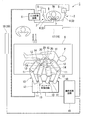
本発明の処置具、マニピュレータ及び手術支援システムについて説明する。図1は、本発明の第1実施形態の手術支援システムの全体図である。
まず、本実施形態の手術支援システム1の構成について説明する。
図1に示すように、本実施形態の手術支援システム1は、マスターアーム2とスレーブアーム10とからなる2種のアームを有し、マスターアーム2の動作に追従させるようにしてスレーブアーム10を遠隔制御するマスタースレーブ方式のシステムである。手術支援システム1には、患者Pに対して処置をする処置具20(図2参照)が取り付けられている。
(First embodiment)
The treatment tool, manipulator, and operation support system of the present invention will be described. FIG. 1 is an overall view of a surgery support system according to a first embodiment of the present invention.
First, the configuration of the
As shown in FIG. 1, the
手術支援システム1は、マスターアーム2と、入力処理回路6と、切替器7と、手術台9と、スレーブアーム10(マニピュレータ)、スレーブ制御回路13と、画像処理回路16と、ディスプレイ19と、を有している。
The
マスターアーム2は、複数のリンク機構3を有する。各リンク機構3は、複数のリンク部材4が互いに連結された構造を有している。各リンク機構3を構成するそれぞれのリンク部材4には、例えばインクリメンタルエンコーダ等の位置検出器5が設けられている。
The
マスターアーム2に設けられた位置検出器5は、各リンク部材4の動作を検出し、検出信号を入力処理回路6へ出力するようになっている。位置検出器5が出力した検出信号は、入力処理回路6に入力され、当該検出信号に基づいて、入力処理回路6においてマスターアーム2の操作量が検出される。
The
入力処理回路6には、上記マスターアーム2と、マスターアーム2の操作に対応して動作するスレーブアーム10を選択するための切替器7とが電気的に接続されている。入力処理回路6は、マスターアーム2の操作量を検出し、検出された操作量に応じてスレーブアーム10を動作させるための信号を生成し、スレーブ制御回路13へ出力する。
切替器7は、たとえばスレーブアーム10の各々に対応する複数の押しボタンスイッチ8を有し、押下された押しボタンスイッチ8に対応した選択信号を入力処理回路6へ出力するようになっている。
また、入力処理回路6には、マスターアーム2とスレーブアーム10との動作比率を変更するスケーリング変更スイッチや、システムを緊急停止させたりするためのフットスイッチ等の操作部材が接続されていてもよい。
The input processing circuit 6 is electrically connected to the
The switch 7 has a plurality of push button switches 8 corresponding to each of the
The input processing circuit 6 may be connected to operation members such as a scaling change switch for changing the operation ratio of the
手術台9は、観察や処置の対象となる患者Pが載置される台である。手術台9の近傍には、スレーブアーム10が設置されている。本実施形態では、1つの手術台9に対して複数のスレーブアーム10が配置されている。
The operating table 9 is a table on which a patient P to be observed and treated is placed. A
各スレーブアーム10は、それぞれ複数の多自由度関節11を有している。各多自由度関節11を湾曲させることによって、手術台9に載置された患者Pに対して各スレーブアーム10の先端側(患者Pの体腔に向かう側)に装着される処置具20等を位置決めする。
Each
各多自由度関節11は、図示しない動力部によって個別に駆動される。動力部としては、例えばインクリメンタルエンコーダや減速器等を備えたサーボ機構を有するモータ(サーボモータ)を採用することができる。動力部による多自由度関節11の動作制御は、スレーブ制御回路13によって行われる。
Each multi-degree-of-freedom joint 11 is individually driven by a power unit (not shown). As the power unit, for example, a motor (servo motor) having a servo mechanism including an incremental encoder, a speed reducer, and the like can be employed. Operation control of the multi-degree-of-freedom joint 11 by the power unit is performed by the
また、スレーブアーム10の姿勢や位置は、動力部に接続された位置検出器12によって検出される。位置検出器12は、動力部の駆動量を検知してスレーブ制御回路13へ検出信号を出力するようになっている。位置検出器12から発せられた検出信号は、スレーブ制御回路13に入力され、この検出信号により、スレーブアーム10の駆動量がスレーブ制御回路13において検出される。
Further, the posture and position of the
スレーブアーム10には、スレーブアーム10に装着された処置具20を駆動するための複数の駆動源21(図2参照)が、多自由度関節11を動作させる動力部とは別に設けられている。
The
スレーブアーム10の遠位端には、スレーブアーム10と処置具20とを接続するための手術用動力伝達アダプタ14が設けられている。手術用動力伝達アダプタ14は、スレーブアーム10と処置具20との間に介在された、スレーブアーム10からの動力を直動運動によって処置具20に伝達する機構を備えた部材である。
A surgical
スレーブ制御回路13は、例えばCPUやメモリ等を有して構成されている。スレーブ制御回路13は、スレーブアーム10の制御を行うための所定のプログラムを記憶しており、入力処理回路6からの制御信号に従って、スレーブアーム10又は処置具20の動作を制御する。
The
具体的には、スレーブ制御回路13は、入力処理回路6からの制御信号に基づいて、操作者Opによって操作されたマスターアーム2の操作対象となるスレーブアーム10または処置具20(以下、「スレーブアーム10等」と称する。)を特定し、スレーブアーム10等を動作させる駆動信号を生成する。さらに、スレーブ制御回路13は、スレーブアーム10の動力部へ駆動信号を出力するとともに、当該スレーブアーム10の動作に従って動力部の位置検出器5から発せられる検出信号に応じて、当該スレーブアーム10が動作目標に到達するように、駆動信号の大きさや極性を制御する。
これにより、スレーブ制御回路13は、マスターアーム2の操作対象として特定されたスレーブアーム10等の動作を制御することができる。
Specifically, the
Thereby, the
本実施形態の手術支援システム1では、マスターアーム2の操作に対応して動作するスレーブアーム10を特定してから特定されたスレーブアーム10を動作させるので、マスターアーム2の数量よりも多くのスレーブアーム10を切り替えて動作させることができる。たとえば、本実施形態では、2本のマスターアーム2を用いて4本のスレーブアーム10を操作することができる。なお、マスターアーム2の数とスレーブアーム10の数とが一致していても構わない。
In the surgical
本実施形態では、複数のスレーブアーム10のうちの少なくとも1つには、処置対象の画像を取得する観察器具15が取り付けられている。観察器具15としては、たとえば医療用内視鏡装置など、公知の観察器具15を適宜採用することができる。本実施形態では、観察器具15によって取得された画像は、スレーブ制御回路13を介して画像処理回路16へ画像信号として出力される。
In this embodiment, an
画像処理回路16は、スレーブ制御回路13から出力された画像信号に対して画像処理を施して、ディスプレイ19(操作者用ディスプレイ17や助手用ディスプレイ18)に表示させる画像データを生成する。
操作者用ディスプレイ17及び助手用ディスプレイ18は、例えば液晶ディスプレイで構成されており、画像処理回路16において生成された画像データに基づく画像を表示する。
The
The
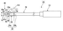
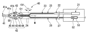
図2は、手術支援システム1に設けられた処置具20を示す側面図である。図3は、処置具20の断面図である。図4は、処置具20における処置部の先端の拡大断面図である。
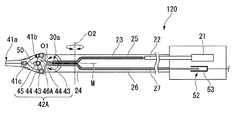
図2及び図3に示すように、処置具20は、いわゆる外科用手術器であり、駆動源21と、本体部24と、屈曲部28を有する処置部40と、変位量検出機構52とを備える。
FIG. 2 is a side view showing the
As shown in FIGS. 2 and 3, the
駆動源21は、例えばサーボモータを備え、スレーブ制御回路13によって動作が制御され、処置部40を作動させる駆動力を発する。駆動源21にはロッド22の一端が固定されており、駆動源21はロッド22の中心軸線方向へロッド22を進退移動させる。ロッド22の他端は、屈曲部28よりも駆動源21側の範囲内に位置している。ロッド22の他端には、可撓性を有する駆動ワイヤ23の一端が固定されている。駆動ワイヤ23の他端は、後述する連結部材42に接続されている。駆動ワイヤ23と連結部材42とは、たとえば溶接などによって固定されている。ロッド22と駆動ワイヤ23とによって本発明の駆動力伝達部材が構成されており、駆動源21が発した駆動力は、駆動源21に連結された駆動力伝達部材を介して処置部40へと伝達されるようになっている。
The
本体部24は、両端が開口された筒状に形成されており、一端が駆動源21に固定されているとともに他端が屈曲部28に固定されている。本体部24の内部には、上述のロッド22及び駆動ワイヤ23と、駆動ワイヤ23が挿通された駆動用ガイド部材25と、センシング用ワイヤ26(作動量検出部材)と、センシング用ワイヤ26が挿通された検出用ガイド部材27とが設けられている。
The
駆動用ガイド部材25は、本体部24内における駆動ワイヤ23の経路を規定して駆動ワイヤ23をガイドする筒状部材である。駆動用ガイド部材25は、たとえばコイルパイプによって形成されている。
センシング用ワイヤ26は、後述する固定部46に一端が固定され、他端が駆動源21内に配置されたワイヤである。本実施形態では、センシング用ワイヤ26は金属線材によって構成されている。
検出用ガイド部材27は、本体部24内におけるセンシング用ワイヤ26の経路を規定してセンシング用ワイヤ26をガイドする筒状部材である。検出用ガイド部材27は、たとえばコイルパイプや金属パイプによって形成されている。また、検出用ガイド部材27の内面とセンシング用ワイヤ26の外面とは、互いの摩擦が小さくなるような表面処理等が施されていてもよい。
駆動用ガイド部材25と検出用ガイド部材27とは、互いに干渉しないように離れた位置に設けられており、屈曲部28においては、互いに平行に配置されている。
The driving
The
The
The
屈曲部28は、略筒状に形成された中間支持部材29と、互いに90度ずれた状態で中間支持部材29の端部にそれぞれ配置された2つの屈曲軸30(第一屈曲軸30a、第二屈曲軸30b)とを有している。本実施形態では、処置部40の先端に近い側に設けられた屈曲軸30(第一屈曲軸30a)は、処置部40を開閉動作させるための後述する開閉軸41cと平行となっている。
The
図5は、処置具20における駆動ワイヤ23とセンシング用ワイヤ26との位置関係を示す模式図である。
図3および図5に示すように、第一屈曲軸30aと第二屈曲軸30bとのそれぞれの近傍において、互いに平行な駆動ワイヤ23とセンシング用ワイヤ26との中央線Mは、第一屈曲軸30aの中心軸線O1と交差し、且つ第二屈曲軸30bの中心軸線O2と交差する。このような位置関係にすることで、固定部46に近い第一屈曲軸30a付近で、駆動ワイヤ、センシング用ワイヤが屈曲方向によって曲げ半径が違うことが避けられ、ワイヤへの屈曲による影響が屈曲方向によって異なることを避けることができる。なお、本明細書においては、駆動ワイヤ23とセンシング用ワイヤ26とを見やすくするために、実際には重なって図示されるべき駆動ワイヤ23とセンシング用ワイヤ26と紙面上下方向にずらして図示している。
FIG. 5 is a schematic diagram showing the positional relationship between the
As shown in FIGS. 3 and 5, in the vicinity of each of the
図3に示すように、屈曲部28は、本体部24内に配された屈曲用ワイヤ(不図示)、及び駆動源21とは別に設けられた駆動源(不図示)によって、駆動源21側に対して処置部40の先端側が2つの屈曲軸30を中心として回動するように屈曲される。
As shown in FIG. 3, the bending
また、処置部40は、開閉軸41cを回動の中心として互いに回動可能な一対のジョー41と、一対のジョー41に連結された連結部材(連結部)42と、一対のジョー41を開閉軸41cを介して支持し、第一屈曲軸30aの中心軸線回りに回動可能に第一屈曲軸30aに取り付けられた支持部材48とを備える。
In addition, the
一対のジョー41は、たとえば患者P(図1参照)の組織を把持したり、縫合糸や針を把持したりする目的で設けられている。一対のジョー41の各々は、開閉軸41c部分において折れ曲がった形状を有し、対向して配置されている。
The pair of
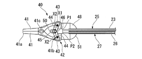
図4に示すように、連結部材42は、一対のジョー41における屈曲部28側に位置する端部41b(一対のジョー41の基端部)のそれぞれにピン43によって回動可能に連結された一対のリンク44と、一対のリンク44のそれぞれにピン45によって回動可能に連結された固定部46とを備える。一対のジョー41と一対のリンク44とをそれぞれ連結するピン43と、一対のリンク44と固定部46とを連結するピン45とは、いずれも開閉軸41cと平行に中心軸線が延びる略円柱状の部材である。
As shown in FIG. 4, the connecting
固定部46には、駆動力伝達部材を構成する駆動ワイヤ23の端部と、センシング用ワイヤ26の端部とが共に固定されている。固定部46と駆動ワイヤ23との固定位置P1と、固定部46とセンシング用ワイヤ26との固定位置P2とは、屈曲部28の第二屈曲軸30bが延びる方向に並んでいる。
Both the end of the
本実施形態では、一対のジョー41と一対のリンク44とを固定する各ピン43は、一対のリンク44と固定部46とを連結するピン45よりも屈曲部28に近い位置に配置されている。このため、固定部46が屈曲部28側へ移動すると、各ピン43の間隔が開くように一対のジョー41の基端部が移動される。また、一対のジョー41が閉じられている状態における各ピン43の距離X1は、ピン43とピン45との間の距離X2の2倍よりも短く設定されている。このため、固定部46が屈曲部28側へ移動されても、ピン45が各ピン43よりも屈曲部28側へ移動されることはない。このとき、ジョー41の先端41a側において、対向する面によって把持対象物を挟み込む力がかかるようになっている。
In the present embodiment, each
さらに、ピン43、45によって連結された一対のリンク44は、トグル機構(倍力機構)を構成している。このため、ジョー41の先端41a側を閉じるために駆動ワイヤ23を牽引するときに、駆動ワイヤ23を介して伝達された駆動力は、当該トグル機構によって減速されて一対のジョー41へと出力される。その結果、駆動源21が発する駆動力よりも大きな力でジョー41を閉じることができる。
Further, the pair of
一対のリンク44及び固定部46は、たとえば一対のジョー41と同程度の剛性を有する部材であり、駆動ワイヤ23を介して伝達された駆動力によっては変形しないようになっている。
このように、連結部材42は、ロッド22及び駆動ワイヤ23を介して駆動源21から伝達された駆動力を処置部40の動作に変換するリンクとして機能する。
The pair of
As described above, the connecting
支持部材48は、開閉軸41cの両端を支持する軸支持部49と、固定部46に設けられたピン45を移動可能に支持する長孔部50と、駆動用ガイド部材25及び検出用ガイド部材27を固定支持するガイド固定部51とを有している。本実施形態では、支持部材48には、屈曲部28の第一屈曲軸30aとなる円柱状の突起48aが外面に一対形成されており、屈曲部28の中間支持部材29には、支持部材48に形成された突起48aが挿通された孔29a(図2参照)が設けられている。
The
ガイド固定部51は、駆動用ガイド部材25から固定部46へ向かう駆動ワイヤ23が、駆動用ガイド部材25の先端から固定位置P1へ向かう直線状となるように、駆動用ガイド部材25を固定支持している。また、ガイド固定部51は、検出用ガイド部材27から固定部46へ向かうセンシング用ワイヤ26が、検出用ガイド部材27の先端から固定位置P2へ向かう直線状となるように、検出用ガイド部材27を固定支持している。
さらに、ガイド固定部51は、駆動用ガイド部材25と固定部46との間及び検出用ガイド部材27と固定部46との間において駆動ワイヤ23とセンシング用ワイヤ26とが平行となるように、駆動用ガイド部材25と検出用ガイド部材27とを固定支持している。
The
Further, the
図3に示すように、変位量検出機構52は、センシング用ワイヤ26の基端(固定部46に固定されていない側の端)の変位量を検出するセンサ53と、センサ53によって検出された変位量を出力する図示しない出力部とを備える。変位量検出機構52のセンサ53は、金属線材によって構成されたセンシング用ワイヤ26のセンサ53に対する位置が変化することによる磁気の変化を検出する磁気センサである。センサ53によって検出されるセンシング用ワイヤ26の変位量は、一対のジョー41の開閉に対応して変化する。このため、センサ53は、センシング用ワイヤ26の変位量を検出することによって一対のジョー41の開閉状態を検出することができる。
As shown in FIG. 3, the displacement
変位量検出機構52の出力部は、センサ53によって検出された変位量をスレーブ制御回路13へと出力する。スレーブ制御回路13では、変位量検出機構52の出力部から出力された変位量に基づいて駆動源21の駆動状態を制御する。
The output unit of the displacement
次に、処置具20、スレーブアーム10(マニピュレータ)及び手術支援システム1の作用について説明する。
手術支援システム1は、スレーブアーム10に処置具20が取り付けられた状態で使用される。
手術支援システム1の操作者Opは、マスターアーム2を操作して、スレーブアーム10及び処置具20を遠隔操作する。処置具20の使用時には、スレーブ制御回路13によって駆動源21が駆動され、駆動源21に接続されたロッド22が進退移動される。すると、ロッド22に固定された駆動ワイヤ23もロッド22と一体に進退移動されて、駆動ワイヤ23に固定された固定部46も進退移動される。固定部46が進退移動されることによって、一対のジョー41は開閉動作される。
Next, operations of the
The
The operator Op of the
一対のジョー41を閉じる動作をさせるときには、駆動ワイヤ23が駆動源21によって牽引されるので、駆動ワイヤ23には牽引力がかかる。牽引力がかかった駆動ワイヤ23は、牽引力によって僅かに伸びる場合がある。したがって、駆動源21によって実際に牽引した駆動ワイヤ23の牽引量と、駆動ワイヤ23が固定部46を牽引する牽引量との間には、駆動ワイヤ23の伸びの分だけズレが生じる可能性がある。特に、一対のジョー41の先端側において処置対象となる組織が挟み込まれている状態では、組織を把持するための強い牽引力が駆動ワイヤ23にかかることで、駆動ワイヤ23の伸びによる上記ズレは一層顕著となる。
When the pair of
駆動ワイヤ23によって固定部46が牽引されると、固定部46に固定されたセンシング用ワイヤ26は、駆動源21側へと押される。センシング用ワイヤ26は固定部46により移動されるだけであり固定部46以外には固定されていないから、センシング用ワイヤ26には、センシング用ワイヤ26に伸びを生じさせるほどの力はかからない。センシング用ワイヤ26は、駆動ワイヤ23の伸びの影響を受けることなく、固定部46の変位量に応じて移動する。
When the fixing
変位量検出機構52のセンサ53は、センシング用ワイヤ26の変位量を検出し、センサ53からの出力を受けたスレーブ制御回路13は、一対のジョー41の開閉状態を検出する。このとき、スレーブ制御回路13によって検出された一対のジョー41の開閉状態は、駆動ワイヤ23の伸びによって生じる駆動ワイヤ23の牽引量と固定部46の移動量とのズレの影響を受けない。すなわち、一対のジョー41の開閉状態が精度よく検出される。
The
また、処置具20の使用時には、屈曲部28が屈曲された状態で一対のジョー41を開閉させる場合もある。この場合、駆動ワイヤ23とセンシング用ワイヤ26とは共に屈曲軸30において屈曲される。本実施形態では、屈曲部28が屈曲されても屈曲部28が直線状態であっても、屈曲部28における駆動ワイヤ23の経路長とセンシング用ワイヤ26の経路長とのいずれも変化しない。このため、屈曲部28の屈曲状態によらず、センシング用ワイヤ26の変位量を検出することにより一対のジョー41の開閉状態が精度良く検出される。
Further, when the
以上説明したように、本実施形態の処置具20、スレーブアーム10(マニピュレータ)、及び手術支援システム1によれば、一対のジョー41を開閉動作させる連結部材42の固定部46に駆動ワイヤ23とセンシング用ワイヤ26とがそれぞれ個別に固定されているので、駆動ワイヤ23の伸びの影響を受けずに一対のジョー41の動作がセンシング用ワイヤ26の変位に精度良く反映される。その結果、処置部40に設けられた一対のジョー41の変位量を精度よく検出することができる。
As described above, according to the
(第2実施形態)
次に、本発明の第2実施形態の処置具、マニピュレータ、及び手術支援システムについて説明する。なお、以下に説明する各実施形態において、上述した第1実施形態の処置具20、マニピュレータ(スレーブアーム10)、及び手術支援システム1と構成を共通とする箇所には同一符号を付けて、説明を省略する。図6は、本実施形態の処置具、マニピュレータ及び手術支援システムにおける処置具の一部の構成を示す模式図である。
(Second Embodiment)
Next, a treatment tool, a manipulator, and a surgery support system according to a second embodiment of the present invention will be described. In each embodiment described below, portions having the same configuration as those of the
本実施形態では、屈曲部28を屈曲させるための機構について詳述する。
図6に示すように、第一屈曲軸30aは、直径が互いに異なる2枚のプーリ(第一プーリ61、第二プーリ62)が同軸状に重ねられた形状を有する多段プーリ60となっている。第一屈曲軸30aは、中間支持部材29に対しては多段プーリ60の回転軸回りに回動自在に支持されており、支持部材48に対しては固定されている。
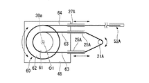
In the present embodiment, a mechanism for bending the
As shown in FIG. 6, the
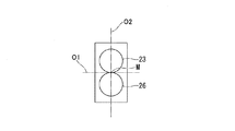
多段プーリ60における直径が小さいほうのプーリ(第一プーリ61)には、多段プーリ60を回転させるための屈曲用ワイヤ63が巻き掛けられている。第一プーリ61の外周面の一部には、屈曲用ワイヤ63の一部が固定されており、第一プーリ61と屈曲用ワイヤ63とがすべらないようになっている。多段プーリ60における直径が大きいほうのプーリ(第二プーリ62)の外周には、一端が多段プーリ60に固定された屈曲検出ワイヤ64が巻き掛けられている。
A
屈曲用ワイヤ63は、第1実施形態で説明した駆動源21とは別に設けられた駆動源21Aに接続されている。本実施形態では、駆動源21Aとしては、屈曲用ワイヤ63が巻き掛けられる回転出力軸を有するサーボモータ等を採用することができる。
The
屈曲検出ワイヤ64は、第1実施形態で説明した変位量検出機構52と同様の変位量検出機構52Aによって変位量が検出されるワイヤである。本実施形態では、変位量検出機構52Aによって検出された変位量に基づいて、スレーブ制御回路13において多段プーリ60の回転量が検出される。
The bending
屈曲用ワイヤ63は、駆動用ガイド部材25と同様の屈曲用ガイド部材25Aに挿通されており、屈曲検出ワイヤ64は、検出用ガイドと同様の屈曲検出用ガイド部材27Aに挿通されている。屈曲用ガイド部材25Aと屈曲検出用ガイド部材27Aとは、いずれも支持部材48に固定されている。
さらに、屈曲用ガイド部材25Aから出て多段プーリ60へ向かう屈曲用ワイヤ63と、屈曲検出用ガイド部材27Aから出て多段プーリ60へ向かう屈曲検出ワイヤ64とは、何れも略直線的に、多段プーリ60との接点へ向かって伸びており、各プーリの接線に沿っている。
The
Further, the
本実施形態の処置具、マニピュレータ、及び手術支援システムの作用について、屈曲部28の作用を中心に説明する。
本実施形態では、屈曲用ワイヤ63が掛け回された第一プーリ61よりも屈曲検出ワイヤ64が掛け回された第二プーリ62の方が直径が大きく形成されている。このため、屈曲用ワイヤ63によって多段プーリ60が回転されると、屈曲用ワイヤ63の変位量よりも屈曲検出ワイヤ64の変位量の方が大きい。また、第1実施形態と同様に、屈曲検出ワイヤ64の変位量は、屈曲用ワイヤ63に牽引力がかかった場合の屈曲用ワイヤ63の伸びの影響を受けることなく、多段プーリ60の回転量が反映される。
The operation of the treatment tool, the manipulator, and the surgery support system according to the present embodiment will be described focusing on the operation of the bending
In this embodiment, the diameter of the
多段プーリ60の回転量は、多段プーリ60が固定された支持部材48の、中間支持部材29に対する屈曲角度となっている。すなわち、本実施形態では、屈曲用ワイヤ63に牽引力がかかった場合の屈曲用ワイヤ63の伸びの影響を受けることなく、中間支持部材29に対する支持部材48の屈曲角度を屈曲検出ワイヤ64を用いて精度良く検出することができる。
The rotation amount of the
また、本実施形態では、多段プーリ60の回転軸が支点となり、直径が小さい第一プーリ61の外周面に屈曲用ワイヤ63が摩擦力により固定されている。さらに、直径が大きい第二プーリ62の外周面には、屈曲検出ワイヤ64が固定されている。このため、屈曲用ワイヤ63の変位量に対する屈曲検出ワイヤ64の変位量を大きくすることができ、変位量検出機構52Aにおける検出の分解能を高めることができる。また、多段プーリ60を構成する各プーリの直径の比率を最適化すれば、変位量検出機構52Aの検出可能範囲(ダイナミックレンジ)の広い領域を検出に利用することができ、ノイズ等の影響を受けにくく、検出精度を高めることができる。
In this embodiment, the rotating shaft of the
なお、第二屈曲軸30bに対しても、本実施形態と同様に多段プーリ60を用いた構成を適用することができる。
さらに、開閉軸41cに対しても、本実施形態と同様に多段プーリ60を用いた構成を適用することができる。
In addition, the structure using the
Furthermore, the structure using the
(変形例)
次に、上記第2実施形態の変形例について説明する。図7は、本変形例の構成を示す模式図である。
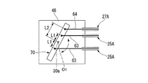
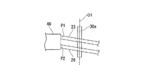
本変形例では、第一屈曲軸30a(図2参照)は、第2実施形態で説明した多段プーリ60ではなく、図7に示すように、第一屈曲軸30aの中心軸線と直交する一方向に延びて形成された梃子部70である点が異なっている。梃子部70は、第一屈曲軸30aの中心軸線O1が支点となり、梃子部70の長手方向に支点から等距離(第一距離L1)となる2点で屈曲用ワイヤ63と固定されている。さらに、屈曲用ワイヤ63と梃子部70との固定点と支点との距離(第一距離L1)よりも長い第二距離L2だけ支点(中心軸線O1)から離れた位置に、屈曲検出ワイヤ64が固定されている。
本変形例でも第2実施形態と同様の効果を奏する。
また、本変形例の場合には、梃子部70は棒状であるので、第2実施形態で説明した円板状の多段プーリ60よりもコンパクトな構成とすることができる。
さらに、本変形例では、屈曲用ワイヤ63が梃子部70に固定されているので、上記第2実施形態における第一プーリ61と屈曲用ワイヤ63との接触面積よりも小さい接触面積で第一プーリ61と屈曲用ワイヤ63とが接触している。このため、摩擦による駆動力の損失が少ない。
(Modification)
Next, a modification of the second embodiment will be described. FIG. 7 is a schematic diagram showing the configuration of this modification.
In the present modification, the
This modification also has the same effect as the second embodiment.
Moreover, in the case of this modification, since the
Further, in this modification, the
(第3実施形態)
次に、本発明の第3実施形態の処置具、マニピュレータ及び手術支援システムについて説明する。本実施形態では、上述の各実施形態で説明した処置具20とは構成が異なる処置具120を有している点が異なっている。
(Third embodiment)
Next, a treatment tool, a manipulator, and a surgery support system according to a third embodiment of the present invention will be described. The present embodiment is different in that it includes a
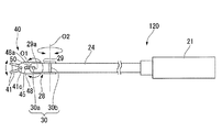
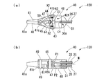
図8は、手術支援システム1に設けられた処置具120を示す側面図である。図9は、処置具120の断面図である。図10(A)、図10(B)は、処置部40の拡大図であり、(A)は側面図、(B)は底面図である。
FIG. 8 is a side view showing the
図8及び図9に示すように、処置具120は、いわゆる外科用手術器であり、駆動源21、本体部24、処置部40、及び変位量検出機構52を備える。さらに、図10(A)および図10(B)に示すように、処置部40は、第1実施形態で説明した連結部42に代えて、一対のジョー41に連結された連結部142を有している。なお、図9においては、駆動ワイヤ23とセンシング用ワイヤ26とを見やすくするために、実際には重なって図示されるべき駆動ワイヤ23とセンシング用ワイヤ26と紙面上下方向にずらして図示している。
As shown in FIGS. 8 and 9, the
連結部142は、連結部材42A(第一連結部材)及びセンシングリンク47(第二連結部材)を有している。
連結部材42Aは、第1実施形態で説明した一対のリンク44と、一対のリンク44のそれぞれにピン45によって回動可能に連結された固定部46Aとを備える。
The connecting portion 142 includes a connecting
The connecting
固定部46Aは、駆動ワイヤ23の端部が固定されている。また、本実施形態では、固定部46Aにはセンシング用ワイヤ26は固定されていない点で上述の第1実施形態と異なっている。
The end of the
図11は、センシングリンク47の構成を示す側面図である。
図10(B)及び図11に示すように、センシングリンク47は、ピン45が挿通される貫通孔を有する剛体であり、ピン45を介して駆動源21からの駆動力が伝達される。また、たとえば一対のジョー41の先端が駆動源21からの駆動力以外の外力を受けて開閉された場合に、当該外力が、一対のジョー41、ピン43、一対のリンク44、ピン45、センシングリンク47にこの順に伝わり、センシングリンク47が移動される。
図10(B)に示すように、センシングリンク47と固定部46Aとはピン45によって連結されているので、センシングリンク47と固定部46Aとは、僅かな遊びによるズレはあるものの概ね一体に動作する。すなわち、一対のジョー41を開閉動作させた場合には、センシングリンク47の変位量は固定部46Aの変位量と実質的に等しい。
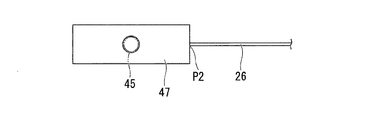
FIG. 11 is a side view showing the configuration of the
As shown in FIGS. 10B and 11, the
As shown in FIG. 10 (B), since the
ガイド固定部51は、駆動用ガイド部材25から固定部46Aへ向かう駆動ワイヤ23が、駆動用ガイド部材25の先端から固定部46A上の固定位置P1へ向かう直線状となるように、駆動用ガイド部材25を固定支持している。また、ガイド固定部51は、検出用ガイド部材27からセンシングリンク47へ向かうセンシング用ワイヤ26が、検出用ガイド部材27の先端からセンシングリンク47上の固定位置P2へ向かう直線状となるように、検出用ガイド部材27を固定支持している。
さらに、ガイド固定部51は、駆動用ガイド部材25と固定部46Aとの間及び検出用ガイド部材27とセンシングリンク47との間において駆動ワイヤ23とセンシング用ワイヤ26とが平行となるように、駆動用ガイド部材25と検出用ガイド部材27とを固定支持している。
The
Further, the
次に、処置具120、スレーブアーム10(マニピュレータ)及び手術支援システム1の作用について、上述の第1実施形態と異なる点を中心に説明する。
Next, operations of the
駆動ワイヤ23によって固定部46Aが牽引されると、ピン45を介して固定部46Aと連結されたセンシングリンク47は、固定部46Aと一体に移動する。ピン45を介して固定部46Aとセンシングリンク47とが連結されていることにより固定部46Aとセンシングリンク47との間には僅かな遊び(クリアランス)があるが、駆動ワイヤ23にかかる牽引力による駆動ワイヤ23の伸びに対して当該遊びは十分に小さい。
When the fixed
センシングリンク47に固定されたセンシング用ワイヤ26は、駆動源21側へと押される。センシング用ワイヤ26はセンシングリンク47により移動されるだけでありセンシングリンク47以外には固定されていないから、センシング用ワイヤ26には、センシング用ワイヤ26に伸びを生じさせるほどの力はかからない。センシング用ワイヤ26は、駆動ワイヤ23の伸びの影響を受けることなく、センシングリンク47の変位量に応じて移動する。センシングリンク47の変位量は固定部46Aの変位量と実質的に等しいので、本実施形態では、センシング用ワイヤ26は、固定部46Aの変位量に応じて移動しているともいえる。
The
変位量検出機構52のセンサ53は、センシング用ワイヤ26の変位量を検出し、センサ53からの出力を受けたスレーブ制御回路13は、一対のジョー41の開閉状態を検出する。このとき、スレーブ制御回路13によって検出された一対のジョー41の開閉状態は、駆動ワイヤ23の伸びによって生じる駆動ワイヤ23の牽引量と固定部46Aの移動量とのズレの影響を受けない。すなわち、一対のジョー41の開閉状態が精度よく検出される。
The
また、処置具120の使用時には、屈曲部28が屈曲された状態で一対のジョー41を開閉させる場合もある。この場合、駆動ワイヤ23とセンシング用ワイヤ26とは共に屈曲軸30において屈曲される。本実施形態では、屈曲部28が屈曲されても屈曲部28が直線状態であっても、屈曲部28における駆動ワイヤ23の経路長とセンシング用ワイヤ26の経路長とのいずれも変化しない。このため、屈曲部28の屈曲状態によらず、センシング用ワイヤ26の変位量を検出することにより一対のジョー41の開閉状態が精度良く検出される。
Further, when the
以上説明したように、本実施形態の処置具120、スレーブアーム10(マニピュレータ)、及び手術支援システム1によれば、一対のジョー41を開閉動作させる連結部材42Aの固定部46Aに駆動ワイヤ23が固定され、固定部46Aと一体に動作するように固定部46Aと連結されたセンシングリンク47にセンシング用ワイヤ26が固定されている。このため、駆動ワイヤ23の伸びの影響を受けずに一対のジョー41の動作がセンシング用ワイヤ26の変位に精度良く反映される。その結果、処置部40に設けられた一対のジョー41の変位量を精度よく検出することができる。
As described above, according to the
(第4実施形態)
次に、本発明の第4実施形態の処置具、マニピュレータ、及び手術支援システムについて説明する。図12は、本実施形態の処置具、マニピュレータ及び手術支援システムにおける処置部の一部の構成を示す模式図である。
(Fourth embodiment)
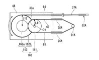
Next, a treatment tool, a manipulator, and a surgery support system according to a fourth embodiment of the present invention will be described. FIG. 12 is a schematic diagram illustrating a partial configuration of a treatment unit in the treatment tool, the manipulator, and the surgery support system according to the present embodiment.
本実施形態では、屈曲部28を屈曲させるための機構について詳述する。
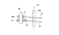
図12に示すように、第一屈曲軸30aは、直径が互いに異なる2枚のプーリ(第一プーリ161、第二プーリ162)が連結された形状を有するプーリ群160となっている。第一屈曲軸30aの中心軸線は、第一プーリ161の回転中心と一致している。
第一プーリ161は、中間支持部材29に対しては第一プーリ161の回転中心回りに回動自在に支持されており、支持部材48に対しては固定されている。第一プーリ161には、プーリ群160を回転させるための屈曲用ワイヤ63が巻き掛けられている。
In the present embodiment, a mechanism for bending the
As shown in FIG. 12, the
The
プーリ群160における直径が大きいほうのプーリ(第二プーリ162)は、第一プーリ161の外周面と摩擦係合する円柱状の係合部162aと、係合部162aと同軸をなす円板状の本体162bとを有する。本体162bの外周には、一端が本体162bに固定された屈曲検出ワイヤ64が巻き掛けられている。
第二プーリ162は、支持部材48に対して回転自在に連結されている。これにより、第一プーリ161が回転されることによって第二プーリ162も回転される。
The pulley having the larger diameter (second pulley 162) in the
The
本実施形態では、第一プーリ161の回転中心(支点)から屈曲用ワイヤ63の固定位置(第一プーリ161の外周面)までの距離(第一距離L11)よりも、第二プーリ162の回転中心(支点)から屈曲検出ワイヤ64の固定位置(本体162bの外周面)までの距離(第二距離L12)が長い。
さらに、第一プーリ161の直径は、第二プーリ162の係合部162aの直径よりも大きく設定されており、第一プーリ161を回転させたとき、第一プーリ161の回転角度よりも第二プーリ162の回転角度の方が大きくなる。
このため、本実施形態では、屈曲用ワイヤ63の変位量に対して屈曲検出ワイヤ64の変位量が大きい。
In the present embodiment, the rotation of the
Further, the diameter of the
For this reason, in this embodiment, the displacement amount of the bending
屈曲用ワイヤ63は、第1実施形態で説明した駆動源21とは別に設けられた駆動源21Aに接続されている。本実施形態では、駆動源21Aとしては、屈曲用ワイヤ63が巻き掛けられる回転出力軸を有するサーボモータ等を採用することができる。
The
屈曲検出ワイヤ64は、第2実施形態で説明した変位量検出機構52Aによって変位量が検出されるワイヤである。本実施形態では、変位量検出機構52Aによって検出された変位量に基づいて、スレーブ制御回路13においてプーリ群160の回転量が検出される。
The bending
屈曲用ワイヤ63は、駆動用ガイド部材25と同様の屈曲用ガイド部材25Aに挿通されており、屈曲検出ワイヤ64は、検出用ガイドと同様の屈曲検出用ガイド部材27Aに挿通されている。屈曲用ガイド部材25Aと屈曲検出用ガイド部材27Aとは、いずれも支持部材48に固定されている。
さらに、屈曲用ガイド部材25Aから出て第一プーリ161へ向かう屈曲用ワイヤ63と、屈曲検出用ガイド部材27Aから出て第二プーリ162の本体162bへ向かう屈曲検出ワイヤ64とは、何れも略直線的に、各プーリとの接点へ向かって伸びており、各プーリの接線に沿っている。
The
Further, the
本実施形態の処置具、マニピュレータ、及び手術支援システムの作用について、屈曲部28の作用を中心に説明する。
本実施形態では、屈曲用ワイヤ63が掛け回された第一プーリ161よりも屈曲検出ワイヤ64が掛け回された第二プーリ162の方が直径が大きく形成されている。また、第一プーリ161と第二プーリ162とは、第一プーリ161の回転角度に対して第二プーリ162の回転角度の方が大きくなるように係合部62aによって係合されている。このため、屈曲用ワイヤ63によって第一プーリ161が回転されると、屈曲用ワイヤ63の変位量よりも屈曲検出ワイヤ64の変位量の方が大きくなる。つまり、プーリ群160は、屈曲用ワイヤ63の移動量に対して屈曲検出ワイヤ64の移動量を増幅する増幅機構となっている。また、第1実施形態と同様に、屈曲検出ワイヤ64の変位量は、屈曲用ワイヤ63に牽引力がかかった場合の屈曲用ワイヤ63の伸びの影響を受けることなく、第二プーリ162の回転量が反映される。
The operation of the treatment tool, the manipulator, and the surgery support system according to the present embodiment will be described focusing on the operation of the bending
In this embodiment, the diameter of the
第一プーリ161の回転量は、第一プーリ161が固定された支持部材48の、中間支持部材29に対する屈曲角度となっている。また、第一プーリ161と第二プーリ162とは摩擦係合されている。第二プーリ162は、中間支持部材29に対する支持部材48の屈曲角度を反映した回転量で回転される。すなわち、本実施形態では、屈曲用ワイヤ63に牽引力がかかった場合の屈曲用ワイヤ63の伸びの影響を受けることなく、中間支持部材29に対する支持部材48の屈曲角度を屈曲検出ワイヤ64を用いて精度良く検出することができる。
The rotation amount of the
また、本実施形態では、屈曲用ワイヤ63の変位量に対する屈曲検出ワイヤ64の変位量を大きくすることができ、変位量検出機構52Aにおける検出の分解能を高めることができる。また、プーリ群160を構成する各プーリの直径の比率や、第一プーリ161から第二プーリ162へ駆動力を伝達する際の減速比を最適化すれば、変位量検出機構52Aの検出可能範囲(ダイナミックレンジ)の広い領域を検出に利用することができ、ノイズ等の影響を受けにくく、検出精度を高めることができる。
In the present embodiment, the displacement amount of the bending
なお、第二屈曲軸30bに対しても、本実施形態と同様にプーリ群160を用いた構成を適用することができる。
さらに、開閉軸41cに対しても、本実施形態と同様にプーリ群160を用いた構成を適用することができる。
In addition, the structure using the
Furthermore, a configuration using the
(第5実施形態)
次に、本発明の第5実施形態の処置具、マニピュレータ及び手術支援システムについて説明する。図13は、本実施形態の処置具の一部の構成を示す模式図である。
(Fifth embodiment)
Next, a treatment tool, a manipulator, and a surgery support system according to a fifth embodiment of the present invention will be described. FIG. 13 is a schematic diagram illustrating a partial configuration of the treatment tool of the present embodiment.
図13に示すように、本実施形態では、上述の第3実施形態で説明した処置具120とは構成が異なる処置具220を有している点が異なっている。
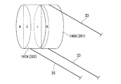
処置具220は、連結部42Aが、固定部46A及びセンシングリンク47に代えて、永久磁石146Aを有する固定部146と、永久磁石147Aを有するセンシングリンク147とを有している。固定部146に設けられた永久磁石146Aとセンシングリンク147に設けられた永久磁石147Aとは、互いに引き合う向きとなるように磁極が配置されている。また、センシングリンク147には、上述の第3実施形態と同様に、センシング用ワイヤ26が固定されている。
As shown in FIG. 13, the present embodiment is different in that it includes a
In the
本実施形態では、固定部146が駆動ワイヤ23により進退移動されると、固定部146に設けられた永久磁石146Aの磁力によりセンシングリンク147に設けられた永久磁石147Aが引き寄せられる。これにより、固定部146の移動と連動してセンシングリンク147が移動する。すなわち、本実施形態では、固定部146とセンシングリンク147とは磁力により非接触状態で連結されており、駆動源21からの駆動力を、磁力を用いて固定部146からセンシングリンク147へ伝達する。その結果、センシングリンク147に固定されたセンシング用ワイヤ26はセンシングリンク147と一体に移動され、上述の第3実施形態と同様に変位量検出機構52により移動量が検出される。
In the present embodiment, when the fixed
このような構成であっても、上述の第3実施形態と同様の効果を奏する。また、本実施形態では、固定部146とセンシングリンク147とが非接触状態で駆動力を伝達することができる。このため、処置具220を滅菌する場合に、薬液や滅菌用ガスが侵入するための隙間が大きく、滅菌しやすい。
Even with such a configuration, the same effects as those of the third embodiment described above can be obtained. Moreover, in this embodiment, the fixing |
(変形例5−1)
次に、本実施形態の処置具220の変形例について説明する。図14は、本実施形態の処置具の変形例の構成を示す模式図である。
図14に示すように、本変形例では、処置部40は、固定部146及びセンシングリンク147に代えて、円板状に形成され永久磁石146Aを有する第一プーリ261と、円板状に形成され永久磁石147Aを有する第二プーリ262を有している。第一プーリ261と第二プーリ262とは、第2実施形態で説明した第一プーリ61及び第二プーリ62と同様に回転中心が同軸状となるように配置されている。また、第一プーリ261と第二プーリ262とは同径である。
(Modification 5-1)
Next, a modified example of the
As shown in FIG. 14, in this modified example, the
また、本変形例における第一プーリ261と第二プーリ262とは互いに固定されてはおらず、駆動源21から発せられ駆動ワイヤ23を通じて伝達された駆動力を第一プーリ261から第二プーリ262へ伝達できるように、永久磁石146A、147Aが引き合う磁力によって連結されている。
本変形例では、第一プーリ261と第二プーリ262とは磁力によって非接触状態で連結されている。このような構成であっても、上述の第2実施形態と同様の効果を奏する。
In addition, the
In this modification, the
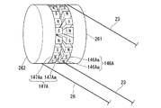
なお、第一プーリ261における永久磁石146Aの配置や、第二プーリ262における永久磁石147Aの配置は、上述の構成には限られない。例えば図15に示すように、第一プーリ261の周縁に複数の磁石片146Aaが配され、第二プーリ262の周縁に複数の磁石片147Aaが配されていてもよい。この場合、第一プーリ261上で隣接する磁石片146Aaは互いに磁極の向きが逆に配置されており、第二プーリ262上で隣接する磁石片147Aaは互いに磁極の向きが逆に配置されていてもよい(図15には、磁極の向きの一例が「N」「S」で示されている。)。このような構成とすることで、磁石片146Aaと磁石片147Aaとが引き合う力及び反発する力を用いて駆動力を伝達することができる。
The arrangement of the
また、永久磁石146A、147Aに代えて、電磁石が採用されていてもよい。
Moreover, it replaces with
また、永久磁石146A、147Aによる磁力を用いて駆動力を伝達することに代えて、静電気の力によって互いに引き合う静電チャックを採用することもできる。この場合、駆動力を伝達する際に第一プーリと第二プーリとが接するように引き付けられるようになっていてもよいし、駆動力を伝達する際においても第一プーリと第二プーリとが非接触状態となっていてもよい。
Further, instead of transmitting the driving force using the magnetic force of the
(変形例5−2)
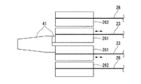
次に、本実施形態の他の変形例について説明する。図16は、本変形例の構成を示す模式図である。
本変形例では、一対のジョー41のそれぞれに対して、第一プーリ261及び第二プーリ262の組が設けられている。このような構成を有していると、一対のジョー41における各ジョーを独立して移動させることができる。
(Modification 5-2)
Next, another modification of the present embodiment will be described. FIG. 16 is a schematic diagram showing the configuration of this modification.
In the present modification, a pair of a
(第6実施形態)
次に、本発明の第6実施形態の処置具、マニピュレータ及び手術支援システムについて説明する。図17は、本実施形態の処置具の一部の構成を示す模式図である。
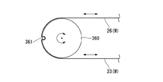
本実施形態では、第一プーリ61及び第二プーリ62が設けられていた第2実施形態の構成に代えて、駆動ワイヤ23とセンシング用ワイヤ26とが共に固定されたプーリ360が設けられた構成となっている。
なお、駆動ワイヤ23とセンシング用ワイヤ26とは、別体のワイヤである必要はなく、一本のワイヤの中間部がプーリ360の周縁部に固定されていれば、当該一本のワイヤが駆動ワイヤ23及びセンシング用ワイヤ26として機能する。本実施形態では、一本のワイヤWがピン361に巻かれた状態でピン361に対してロウ付けあるいは溶接により固定され、ピン361がプーリ360に嵌め込まれることにより、ワイヤWがプーリ360に固定されている。なお、ワイヤWとプーリ360との固定方法はピン361を使用する方法には限られない。例えば、ワイヤWの外周面をプーリ360の外面に溶接、半田付け、あるいはロウ付けによって固定してもよい。
(Sixth embodiment)
Next, a treatment tool, a manipulator, and a surgery support system according to a sixth embodiment of the present invention will be described. FIG. 17 is a schematic diagram illustrating a partial configuration of the treatment tool of the present embodiment.
In this embodiment, instead of the configuration of the second embodiment in which the
The
本実施形態では、駆動ワイヤ23を押し引きすることによってプーリ260を回動させて、上述の第2実施形態や第4実施形態と同様に一対のジョー41を開閉させる。このとき、プーリ360にセンシング用ワイヤ26が固定されているので、センシング用ワイヤ26はプーリ360と一体に移動される。さらに、センシング用ワイヤ26がプーリ360に固定されているので、駆動ワイヤ23が牽引された場合にも、センシング用ワイヤ26がプーリ360に固定された状態である限りは、センシング用ワイヤ26には牽引力が伝わらない。本実施形態においても、上述の各実施形態と同様の効果を奏する。
In the present embodiment, the pulley 260 is rotated by pushing and pulling the
以上、本発明の実施形態について図面を参照して詳述したが、具体的な構成はこの実施形態に限られるものではなく、本発明の要旨を逸脱しない範囲の設計変更等も含まれる。
たとえば、上述の第1実施形態では、第一屈曲軸30aの中心軸線と、第二屈曲軸30bの中心軸線との両方に直交するように駆動ワイヤ23とセンシング用ワイヤ26が引き回されている例が開示されているが、第一屈曲軸30aや第二屈曲軸30bが中間支持部材29の長手方向(軸方向)と直交方向に伸びる柱状部材である場合には、柱状部材(第一屈曲軸30a)の外周に沿って、柱状部材(第一屈曲軸30a)の中心軸線O1に対してねじれの位置となるように駆動ワイヤ23とセンシング用ワイヤ26とが互いに略等しく近接されて引き回されていてもよい(図18参照)。この場合には、固定部46に近い第一屈曲軸30a付近で、駆動ワイヤ23、センシング用ワイヤ26が屈曲方向によって曲げ半径が違うことが避けられ、ワイヤ23,26への屈曲による影響が屈曲方向によって異なることを避けることができる。尚、柱状部材に対するワイヤ23,26の投影面が垂直になるのも良い。この場合が特に効果がある。
As mentioned above, although embodiment of this invention was explained in full detail with reference to drawings, the concrete structure is not restricted to this embodiment, The design change etc. of the range which does not deviate from the summary of this invention are included.
For example, in the first embodiment described above, the
また、上述の第3実施形態では、第一屈曲軸30aの中心軸線と、第二屈曲軸30bの中心軸線との両方に直交するように駆動ワイヤ23とセンシング用ワイヤ26が引き回されている例が開示されているが、第一屈曲軸30aや第二屈曲軸30bが中間支持部材29の長手方向(軸方向)と直交方向に伸びる柱状部材である場合には、柱状部材(第一屈曲軸30a)の外周に沿って、柱状部材(第一屈曲軸30a)の中心軸線O1に対してねじれの位置となるように駆動ワイヤ23とセンシング用ワイヤ26とが互いに略等しく近接されて引き回されていてもよい(図19参照)。この場合には、固定部46Aに近い第一屈曲軸30a付近で、駆動ワイヤ23、センシング用ワイヤ26が屈曲方向によって曲げ半径が違うことが避けられ、ワイヤ23,26への屈曲による影響が屈曲方向によって異なることを避けることができる。尚、柱状部材に対するワイヤ23,26が延びる投影面が垂直になるのも良い。この場合が特に効果がある。
In the third embodiment described above, the
また、上述の第1実施形態では、固定部46に駆動ワイヤ23が直接固定されている例を示したが、固定部46に対して駆動ワイヤ23が間接的に固定されていても構わない。例えば、固定部46及び駆動ワイヤ23に共に固定される中間部材を有していてもよい。また、例えば駆動ワイヤ23が挿通される貫通孔が固定部46に形成され、当該貫通孔に駆動ワイヤ23が挿通された状態で駆動ワイヤ23の端部が固定部46に固定されてもよい。
In the above-described first embodiment, the example in which the
また、上述の第1実施形態では、開閉機構として、トグル機構を例にとって説明したが、いわゆるパンタグラフ機構であってもよい。
また、上述の各実施形態では、処置部の連結部として、処置部である一対のジョー41に対してリンク44、固定部46が設けられたものを例にとって説明したが、処置部と連結部材が一体であっても良い。この場合、例えば一対のジョー41のうち一方を固定とし、他方が開閉可能とすれば、その他方のジョー41の基端部が駆動ワイヤ23、センシング用ワイヤ26が固定される連結部材を成すことになり、ジョーと連結部材とは一体となる。
In the first embodiment described above, the toggle mechanism is described as an example of the opening / closing mechanism. However, a so-called pantograph mechanism may be used.
Further, in each of the above-described embodiments, the treatment unit and the connection member are described as an example in which the
また、駆動ワイヤ及びセンシング用ワイヤの材質は、特に限定されない。たとえば、ステンレスやタングステンなどの金属製のワイヤや、ポリアリレートなどの樹脂製のワイヤを採用することができる。樹脂製のワイヤの変位量を磁気式のセンサによって検出する場合には、磁気式のセンサ付近に位置するワイヤに、金属製の細径パイプをかぶせたり、金属をコーティングしたり、金属製のワイヤを接続するなどの加工が施されていればよい。 Further, the materials of the drive wire and the sensing wire are not particularly limited. For example, a metal wire such as stainless steel or tungsten, or a resin wire such as polyarylate can be employed. When detecting the displacement of a resin wire with a magnetic sensor, the wire located near the magnetic sensor is covered with a thin metal pipe, coated with metal, or metal wire. It is sufficient that processing such as connecting is performed.
また、上述の各実施形態では、センシング用ワイヤの変位を検出するセンサとして、磁気式のセンサが採用されている例を示したが、センシング用ワイヤの変位を検出するセンサは、磁気式には限られない。たとえば、センシング用ワイヤの変位を検出するセンサとして、光学式、静電容量式、またはポテンショメータなどを採用することもできる。 In each of the above-described embodiments, a magnetic sensor is used as a sensor for detecting the displacement of the sensing wire. However, the sensor for detecting the displacement of the sensing wire is a magnetic sensor. Not limited. For example, as a sensor for detecting the displacement of the sensing wire, an optical type, a capacitance type, a potentiometer, or the like may be employed.
また、上述の各実施形態及びその変形例では、処置部に設けられた一対のジョーや屈曲部の動作を検出する例を示したが、スレーブアームの各関節の変位を検出するために本発明の構成を適用することもできる。 Further, in each of the above-described embodiments and the modifications thereof, an example in which the operation of the pair of jaws and the bending portion provided in the treatment portion is illustrated, but the present invention is used to detect the displacement of each joint of the slave arm. The configuration of can also be applied.
また、上述の各実施形態及びその変形例において示した構成要素は適宜に組み合わせて構成することが可能である。 In addition, the constituent elements shown in each of the above-described embodiments and modifications thereof can be appropriately combined.
1 手術支援システム
2 マスターアーム
3 リンク機構
4 リンク部材
5 位置検出器
6 入力処理回路
7 切替器
8 押しボタンスイッチ
9 手術台
10 スレーブアーム
11 多自由度関節
12 位置検出器
13 スレーブ制御回路
14 手術用動力伝達アダプタ
15 観察器具
16 画像処理回路
19 ディスプレイ
20,120 処置具
21,21A 駆動源
22 ロッド(駆動力伝達部材)
23 駆動ワイヤ(駆動力伝達部材)
24 本体部
25 駆動用ガイド部材
26 センシング用ワイヤ(作動量検出部材)
27 検出用ガイド部材
28 屈曲部
29 中間支持部材
30 屈曲軸
30a 第一屈曲軸
30b 第二屈曲軸
40 処置部
41 ジョー
41c 開閉軸
42 連結部(連結部材)
42A 連結部材(第一連結部材)
43 ピン
44 リンク
45 ピン
46,46A 固定部
48 支持部材
47 センシングリンク(第二連結部材)
49 軸支持部
50 長孔部
51 ガイド固定部
52、52A 変位量検出機構
53 センサ
60 多段プーリ
61 第一プーリ
62 第二プーリ
63 屈曲用ワイヤ(駆動力伝達部材)
64 屈曲検出ワイヤ(作動量検出部材)
70 梃子部
142 連結部
146 固定部
146A 永久磁石
146Aa 磁石片
147 センシングリンク
147A 永久磁石
147Aa 磁石片
160 プーリ群
161 第一プーリ
162 第二プーリ
261 第一プーリ
262 第二プーリ
360 プーリ
L1 第一距離
L2 第二距離
L11 第一距離
L12 第二距離
O1 中心軸線
O2 中心軸線
Op 操作者
P 患者
P1 固定位置
P2 固定位置
DESCRIPTION OF
23 Drive wire (drive force transmission member)
24
27
42A connecting member (first connecting member)
43
49
64 Bending detection wire (operation amount detection member)
70 Insulator part 142
Claims (8)
前記駆動源に連結された線状の駆動力伝達部材と、
前記処置部に設けられ、前記駆動力伝達部材が接続され、前記駆動源から前記駆動力伝達部材を介して前記駆動力が伝達され該駆動力を前記処置部の動作に変換する連結部と、
前記連結部により移動される線状の作動量検出部材と、
を備え、
前記連結部は、
所定の支点を回動中心として回動可能であり前記所定の支点から第一距離だけ離間した外周に前記駆動力伝達部材が巻き掛けられた第一プーリと、
前記第一プーリの回転中心と同軸状に回転中心を有して回動可能であり前記第一プーリよりも直径が大きく前記第一距離よりも長い第二距離だけ前記所定の支点から離間した外周に前記作動量検出部材が巻き掛けられた第二プーリと、
を有し、
前記駆動力伝達部材は、前記第一プーリに固定され、
前記作動量検出部材は、前記第二プーリに固定されている
ことを特徴とする処置具。 A treatment tool in which a treatment section is activated by a driving force generated by a drive source,
A linear driving force transmission member connected to the driving source;
A connecting portion provided in the treatment portion, connected to the driving force transmission member, and transmitting the driving force from the driving source via the driving force transmission member, and converting the driving force into an operation of the treatment portion;
A linear actuating amount detection member moved by the connecting portion;
Equipped with a,
The connecting portion is
A first pulley, which is rotatable about a predetermined fulcrum as a rotation center, and wherein the driving force transmission member is wound around an outer periphery separated from the predetermined fulcrum by a first distance;
An outer periphery that is rotatable about a rotation center coaxial with the rotation center of the first pulley and is spaced from the predetermined fulcrum by a second distance that is larger in diameter than the first pulley and longer than the first distance. A second pulley around which the operation amount detection member is wound,
Have
The driving force transmission member is fixed to the first pulley;
The treatment tool , wherein the operation amount detection member is fixed to the second pulley .
前記駆動力伝達部材をガイドする駆動用ガイド部材と、
前記作動量検出部材をガイドする検出用ガイド部材と、
前記駆動用ガイド部材及び前記検出用ガイド部材を固定支持する支持部材と、
を備えることを特徴とする処置具。 The treatment tool according to claim 1 ,
A driving guide member for guiding the driving force transmitting member;
A detection guide member for guiding the operation amount detection member;
A support member for fixing and supporting the drive guide member and the detection guide member;
A treatment instrument comprising:
前記支持部材は、
前記駆動用ガイド部材から前記第一プーリへ向かう前記駆動力伝達部材が、前記駆動用ガイド部材の先端から前記駆動力伝達部材と前記第一プーリとの接点へ向かう直線状となるように、前記駆動用ガイド部材を固定支持し、
前記検出用ガイド部材から前記第二プーリへ向かう前記作動量検出部材が、前記検出用ガイド部材の先端から前記作動量検出部材と前記第二プーリとの接点に向かう直線状となるように、前記検出用ガイド部材を固定支持する
ことを特徴とする処置具。 The treatment tool according to claim 2 ,
The support member is
As the driving force transmitting member extending from said driving guide member to said first pulley, a straight line from the tip of the driving guide member toward the contact point between the first pulley and the driving force transmitting member, said Fixedly supporting the drive guide member,
As the operation amount detecting member toward the second pulley from the detection guide member, a straight line extending from the tip of the detection guide members contact with said second pulley and said operation amount detecting member, the A treatment tool characterized by fixing and supporting a detection guide member.
前記支持部材は、前記駆動用ガイド部材と前記第一プーリとの間及び前記検出用ガイド部材と前記第二プーリとの間において前記駆動力伝達部材と前記作動量検出部材とが平行となるように、前記駆動用ガイド部材と前記検出用ガイド部材とを固定支持していることを特徴とする処置具。 The treatment tool according to claim 2 or 3 ,
In the supporting member, the driving force transmission member and the operation amount detecting member are parallel between the driving guide member and the first pulley and between the detection guide member and the second pulley. Further, the treatment tool characterized in that the driving guide member and the detection guide member are fixedly supported.
前記駆動力伝達部材及び前記作動量検出部材がともに屈曲される屈曲部が前記処置部と前記駆動源との間に設けられ、
前記屈曲部は、前記駆動源側に対して前記処置部側が所定の屈曲軸を中心として回動し、
前記駆動力伝達部材及び前記作動量検出部材は、前記屈曲軸近傍において前記屈曲軸との距離が互いに略等しくなるように配置されていることを特徴とする処置具。 The treatment instrument according to any one of claims 1 to 4 ,
A bending portion where the driving force transmission member and the operation amount detection member are bent together is provided between the treatment portion and the driving source,
The bending portion rotates around the predetermined bending axis on the treatment portion side with respect to the drive source side,
The treatment instrument, wherein the driving force transmission member and the operation amount detection member are arranged so that the distance from the bending axis is substantially equal to each other in the vicinity of the bending axis.
前記駆動力伝達部材並びに前記作動量検出部材がワイヤであることを特徴とする処置具。 A treatment instrument according to any one of claims 1 to 5 ,
The treatment tool, wherein the driving force transmission member and the operation amount detection member are wires.
前記処置具が取り付けられたアームと、
を備えることを特徴とするマニピュレータ。 The treatment instrument according to any one of claims 1 to 6 ,
An arm to which the treatment tool is attached;
A manipulator comprising:
Priority Applications (5)
| Application Number | Priority Date | Filing Date | Title |
|---|---|---|---|
| JP2012116742A JP6027770B2 (en) | 2011-06-30 | 2012-05-22 | Treatment instrument, manipulator, and surgery support system |
| EP12805135.6A EP2726010B1 (en) | 2011-06-30 | 2012-06-27 | Treatment tool, manipulator, and surgery support system |
| PCT/JP2012/067027 WO2013002414A1 (en) | 2011-06-30 | 2012-06-27 | Treatment tool, manipulator, and surgery support system |
| CN201280030182.6A CN103619279B (en) | 2011-06-30 | 2012-06-27 | Treatment tool, mechanical hand and operation support system |
| US14/138,216 US9770299B2 (en) | 2011-06-30 | 2013-12-23 | Treatment tool, manipulator, and surgery support system |
Applications Claiming Priority (5)
| Application Number | Priority Date | Filing Date | Title |
|---|---|---|---|
| JP2011146796 | 2011-06-30 | ||
| JP2011146796 | 2011-06-30 | ||
| JP2011146797 | 2011-06-30 | ||
| JP2011146797 | 2011-06-30 | ||
| JP2012116742A JP6027770B2 (en) | 2011-06-30 | 2012-05-22 | Treatment instrument, manipulator, and surgery support system |
Publications (2)
| Publication Number | Publication Date |
|---|---|
| JP2013031637A JP2013031637A (en) | 2013-02-14 |
| JP6027770B2 true JP6027770B2 (en) | 2016-11-16 |
Family
ID=47424298
Family Applications (1)
| Application Number | Title | Priority Date | Filing Date |
|---|---|---|---|
| JP2012116742A Active JP6027770B2 (en) | 2011-06-30 | 2012-05-22 | Treatment instrument, manipulator, and surgery support system |
Country Status (5)
| Country | Link |
|---|---|
| US (1) | US9770299B2 (en) |
| EP (1) | EP2726010B1 (en) |
| JP (1) | JP6027770B2 (en) |
| CN (1) | CN103619279B (en) |
| WO (1) | WO2013002414A1 (en) |
Families Citing this family (24)
| Publication number | Priority date | Publication date | Assignee | Title |
|---|---|---|---|---|
| WO2011115311A1 (en) * | 2010-03-15 | 2011-09-22 | 주식회사 아덴 | Surgical tool |
| JP6049585B2 (en) * | 2013-10-31 | 2016-12-21 | オリンパス株式会社 | Surgical tool |
| JP5980764B2 (en) * | 2013-11-29 | 2016-08-31 | オリンパス株式会社 | Surgical tool |
| CN104827465B (en) * | 2015-05-08 | 2016-10-12 | 上海交通大学 | A kind of mechanical driving device with high actuating speed and large driving force |
| US10973595B2 (en) * | 2015-08-13 | 2021-04-13 | Siemens Healthcare Gmbh | Device and method for controlling a system comprising an imaging modality |
| ITUB20154977A1 (en) | 2015-10-16 | 2017-04-16 | Medical Microinstruments S R L | Medical instrument and method of manufacture of said medical instrument |
| GB2552383B (en) * | 2016-07-22 | 2022-08-24 | Cmr Surgical Ltd | Gear packaging for robotic joints |
| CN113349932A (en) | 2016-12-20 | 2021-09-07 | 威博外科公司 | Sterile adapter control system and communication interface for robotic surgical system |
| WO2019092843A1 (en) | 2017-11-10 | 2019-05-16 | オリンパス株式会社 | Medical manipulator system and method for operating same |
| CN108113751A (en) * | 2017-12-28 | 2018-06-05 | 深圳市罗伯医疗科技有限公司 | A kind of control system and method applied to endoscopic surgery robot |
| CN109984777B (en) * | 2017-12-29 | 2022-02-08 | 江苏木偶医疗科技有限公司 | Drive structure and device with flexible joint |
| RU2682931C1 (en) * | 2018-01-10 | 2019-03-22 | Федеральное государственное бюджетное образовательное учреждение высшего образования "Казанский национальный исследовательский технический университет им. А.Н. Туполева-КАИ" (КНИТУ-КАИ) | Intraoperative thoracic blood flow analyzer |
| CN110236676B (en) * | 2018-03-09 | 2021-02-02 | 深圳市精锋医疗科技有限公司 | Surgical robot |
| WO2019207674A1 (en) * | 2018-04-25 | 2019-10-31 | オリンパス株式会社 | Driving device and medical manipulator |
| US11553939B2 (en) | 2018-10-31 | 2023-01-17 | Cilag Gmbh International | Surgical instruments with a retention feature that retains a cutting element |
| US11406442B2 (en) | 2018-11-05 | 2022-08-09 | Cilag Gmbh International | Articulate wrist with flexible central member |
| JP6791516B1 (en) * | 2019-10-17 | 2020-11-25 | リバーフィールド株式会社 | Surgical robot surgical tools |
| US12070208B2 (en) | 2019-12-30 | 2024-08-27 | Beijing Surgerii Robotics Company Limited | Surgical effector, surgical tool and surgical robot |
| EP4110221A1 (en) * | 2020-02-26 | 2023-01-04 | Covidien LP | Robotic surgical instrument including linear encoders for measuring cable displacement |
| CN113197673A (en) * | 2021-04-28 | 2021-08-03 | 康诺思腾机器人(深圳)有限公司 | Input device and surgical robot |
| KR102576536B1 (en) * | 2021-07-15 | 2023-09-08 | 주식회사 엔도로보틱스 | Device for driving tendon-sheath |
| KR102576537B1 (en) * | 2021-07-15 | 2023-09-08 | 주식회사 엔도로보틱스 | Device for driving tendon-sheath |
| CN115401722B (en) | 2021-05-28 | 2026-03-13 | 恩多机器人技术有限公司 | Lasso drive mechanism |
| WO2023287247A1 (en) * | 2021-07-15 | 2023-01-19 | 주식회사 엔도로보틱스 | Moving device |
Family Cites Families (19)
| Publication number | Priority date | Publication date | Assignee | Title |
|---|---|---|---|---|
| US4500780A (en) * | 1983-01-03 | 1985-02-19 | Pitney Bowes Inc. | Apparatus and method for aligning postage meter components with an optical sensor |
| JPH04263831A (en) | 1991-02-19 | 1992-09-18 | Olympus Optical Co Ltd | Detecting device for curvature shape of inserting part of endoscope |
| JPH1110575A (en) | 1997-06-26 | 1999-01-19 | Toshiba Mach Co Ltd | Parallel link mechanism |
| JPH1177577A (en) | 1997-09-02 | 1999-03-23 | Toshiba Mach Co Ltd | Wire driving type manipulator |
| JP4117954B2 (en) | 1998-12-14 | 2008-07-16 | 三菱プレシジョン株式会社 | Haptic interface device with 4-axis force feedback |
| WO2000040419A1 (en) * | 1999-01-07 | 2000-07-13 | Seiko Epson Corporation | Sensing mechanism, carriage monitor device, and printer comprising the same |
| JP4360860B2 (en) | 2003-07-11 | 2009-11-11 | Hoya株式会社 | Endoscope bending operation device |
| JP2005349489A (en) | 2004-06-08 | 2005-12-22 | Sharp Corp | Multi-degree-of-freedom multi-fingered hand |
| ATE543455T1 (en) * | 2005-03-29 | 2012-02-15 | Toshiba Kk | MANIPULATOR |
| JP4506716B2 (en) * | 2006-04-24 | 2010-07-21 | トヨタ自動車株式会社 | Legged robot |
| JP4960112B2 (en) * | 2007-02-01 | 2012-06-27 | オリンパスメディカルシステムズ株式会社 | Endoscopic surgery device |
| JP5090045B2 (en) * | 2007-04-03 | 2012-12-05 | テルモ株式会社 | Manipulator and control method thereof |
| JP5042738B2 (en) * | 2007-07-30 | 2012-10-03 | テルモ株式会社 | Working mechanism and cleaning method of medical manipulator |
| US8224484B2 (en) * | 2007-09-30 | 2012-07-17 | Intuitive Surgical Operations, Inc. | Methods of user interface with alternate tool mode for robotic surgical tools |
| US9259274B2 (en) * | 2008-09-30 | 2016-02-16 | Intuitive Surgical Operations, Inc. | Passive preload and capstan drive for surgical instruments |
| JP2010220685A (en) | 2009-03-19 | 2010-10-07 | Olympus Corp | Manipulator |
| JP5325621B2 (en) | 2009-03-19 | 2013-10-23 | オリンパス株式会社 | Detection mechanism of joint displacement of manipulator |
| JP5559996B2 (en) * | 2009-07-13 | 2014-07-23 | 富士フイルム株式会社 | Endoscope device, endoscope system, and operation method of endoscope device |
| JP2011089797A (en) * | 2009-10-20 | 2011-05-06 | Olympus Corp | Rotary encoder and medical manipulator using the same |
-
2012
- 2012-05-22 JP JP2012116742A patent/JP6027770B2/en active Active
- 2012-06-27 EP EP12805135.6A patent/EP2726010B1/en active Active
- 2012-06-27 WO PCT/JP2012/067027 patent/WO2013002414A1/en not_active Ceased
- 2012-06-27 CN CN201280030182.6A patent/CN103619279B/en active Active
-
2013
- 2013-12-23 US US14/138,216 patent/US9770299B2/en active Active
Also Published As
| Publication number | Publication date |
|---|---|
| EP2726010B1 (en) | 2017-02-15 |
| CN103619279B (en) | 2016-10-05 |
| EP2726010A4 (en) | 2015-08-19 |
| US9770299B2 (en) | 2017-09-26 |
| EP2726010A1 (en) | 2014-05-07 |
| JP2013031637A (en) | 2013-02-14 |
| WO2013002414A1 (en) | 2013-01-03 |
| US20140107667A1 (en) | 2014-04-17 |
| CN103619279A (en) | 2014-03-05 |
Similar Documents
| Publication | Publication Date | Title |
|---|---|---|
| JP6027770B2 (en) | Treatment instrument, manipulator, and surgery support system | |
| US12133698B2 (en) | Electromechanical surgical system | |
| JP7603617B2 (en) | Actively controlled steerable medical device with passive bending modes | |
| JP6049585B2 (en) | Surgical tool | |
| JP6033516B1 (en) | Medical treatment tool | |
| JP6001189B2 (en) | manipulator | |
| CN107530134B (en) | Electromechanical Surgical System | |
| JP6230430B2 (en) | Surgical instrument and medical manipulator system | |
| JP5856817B2 (en) | Medical treatment tool and manipulator having the same | |
| JP5980764B2 (en) | Surgical tool | |
| JP2012187311A (en) | Medical treatment tool and manipulator | |
| JP6329528B2 (en) | Treatment tool | |
| WO2015012242A1 (en) | Manipulator system | |
| JP5325621B2 (en) | Detection mechanism of joint displacement of manipulator | |
| US10085616B2 (en) | Endoscope system configured to prevent mis-insertion of treatment tool in channel and method of operating the same |
Legal Events
| Date | Code | Title | Description |
|---|---|---|---|
| A621 | Written request for application examination |
Free format text: JAPANESE INTERMEDIATE CODE: A621 Effective date: 20150319 |
|
| A131 | Notification of reasons for refusal |
Free format text: JAPANESE INTERMEDIATE CODE: A131 Effective date: 20160216 |
|
| A521 | Request for written amendment filed |
Free format text: JAPANESE INTERMEDIATE CODE: A523 Effective date: 20160408 |
|
| A521 | Request for written amendment filed |
Free format text: JAPANESE INTERMEDIATE CODE: A821 Effective date: 20160411 |
|
| TRDD | Decision of grant or rejection written | ||
| A01 | Written decision to grant a patent or to grant a registration (utility model) |
Free format text: JAPANESE INTERMEDIATE CODE: A01 Effective date: 20161004 |
|
| A61 | First payment of annual fees (during grant procedure) |
Free format text: JAPANESE INTERMEDIATE CODE: A61 Effective date: 20161017 |
|
| R151 | Written notification of patent or utility model registration |
Ref document number: 6027770 Country of ref document: JP Free format text: JAPANESE INTERMEDIATE CODE: R151 |
|
| R250 | Receipt of annual fees |
Free format text: JAPANESE INTERMEDIATE CODE: R250 |
|
| R250 | Receipt of annual fees |
Free format text: JAPANESE INTERMEDIATE CODE: R250 |
|
| R250 | Receipt of annual fees |
Free format text: JAPANESE INTERMEDIATE CODE: R250 |
|
| R250 | Receipt of annual fees |
Free format text: JAPANESE INTERMEDIATE CODE: R250 |
|
| R250 | Receipt of annual fees |
Free format text: JAPANESE INTERMEDIATE CODE: R250 |
|
| R250 | Receipt of annual fees |
Free format text: JAPANESE INTERMEDIATE CODE: R250 |
|
| R250 | Receipt of annual fees |
Free format text: JAPANESE INTERMEDIATE CODE: R250 |