JP6024971B2 - Rotation angle detector - Google Patents
Rotation angle detector Download PDFInfo
- Publication number
- JP6024971B2 JP6024971B2 JP2012271640A JP2012271640A JP6024971B2 JP 6024971 B2 JP6024971 B2 JP 6024971B2 JP 2012271640 A JP2012271640 A JP 2012271640A JP 2012271640 A JP2012271640 A JP 2012271640A JP 6024971 B2 JP6024971 B2 JP 6024971B2
- Authority
- JP
- Japan
- Prior art keywords
- magnetic
- rotation angle
- output signal
- magnetic sensor
- magnetic pole
- Prior art date
- Legal status (The legal status is an assumption and is not a legal conclusion. Google has not performed a legal analysis and makes no representation as to the accuracy of the status listed.)
- Expired - Fee Related
Links
Images


Classifications
-
- G—PHYSICS
- G01—MEASURING; TESTING
- G01B—MEASURING LENGTH, THICKNESS OR SIMILAR LINEAR DIMENSIONS; MEASURING ANGLES; MEASURING AREAS; MEASURING IRREGULARITIES OF SURFACES OR CONTOURS
- G01B7/00—Measuring arrangements characterised by the use of electric or magnetic techniques
- G01B7/30—Measuring arrangements characterised by the use of electric or magnetic techniques for measuring angles or tapers; for testing the alignment of axes
-
- G—PHYSICS
- G01—MEASURING; TESTING
- G01D—MEASURING NOT SPECIALLY ADAPTED FOR A SPECIFIC VARIABLE; ARRANGEMENTS FOR MEASURING TWO OR MORE VARIABLES NOT COVERED IN A SINGLE OTHER SUBCLASS; TARIFF METERING APPARATUS; MEASURING OR TESTING NOT OTHERWISE PROVIDED FOR
- G01D5/00—Mechanical means for transferring the output of a sensing member; Means for converting the output of a sensing member to another variable where the form or nature of the sensing member does not constrain the means for converting; Transducers not specially adapted for a specific variable
- G01D5/12—Mechanical means for transferring the output of a sensing member; Means for converting the output of a sensing member to another variable where the form or nature of the sensing member does not constrain the means for converting; Transducers not specially adapted for a specific variable using electric or magnetic means
- G01D5/244—Mechanical means for transferring the output of a sensing member; Means for converting the output of a sensing member to another variable where the form or nature of the sensing member does not constrain the means for converting; Transducers not specially adapted for a specific variable using electric or magnetic means influencing characteristics of pulses or pulse trains; generating pulses or pulse trains
Landscapes
- Physics & Mathematics (AREA)
- General Physics & Mathematics (AREA)
- Power Steering Mechanism (AREA)
- Measurement Of Length, Angles, Or The Like Using Electric Or Magnetic Means (AREA)
- Transmission And Conversion Of Sensor Element Output (AREA)
Description
この発明は、回転体の回転角を検出する回転角検出装置に関する。 The present invention relates to a rotation angle detection device that detects a rotation angle of a rotating body.
回転体の回転角を検出する回転角検出装置として、ブラシレスモータの回転に応じて回転する検出用ロータを用いて、ブラシレスモータのロータの回転角を検出する回転角検出装置が知られている。具体的には、図16に示すように、検出用ロータ201(以下、「ロータ201」という)は、ブラシレスモータのロータに設けられている磁極対に相当する複数の磁極対を有する円筒状の磁石202を備えている。ロータ201の周囲には、2つの磁気センサ221,222が、ロータ201の回転中心軸を中心として所定の角度間隔をおいて配置されている。各磁気センサ221,222からは、所定の位相差を有する正弦波信号が出力される。これらの2つの正弦波信号に基づいて、ロータ201の回転角(ブラシレスモータのロータの回転角)が検出される。
As a rotation angle detection device that detects the rotation angle of a rotating body, a rotation angle detection device that detects a rotation angle of a rotor of a brushless motor using a detection rotor that rotates in accordance with the rotation of the brushless motor is known. Specifically, as shown in FIG. 16, a detection rotor 201 (hereinafter referred to as “
この例では、磁石202は、5組の磁極対を有している。つまり、磁石102は、等角度間隔で配置された10個の磁極を有している。各磁極は、ロータ201の回転中心軸を中心として、36°(電気角では180°)の角度間隔で配置されている。また、2つの磁気センサ221,222は、ロータ201の回転中心軸を中心として18°(電気角では90°)の角度間隔をおいて配置されている。
In this example, the
図16に矢印で示す方向を検出用ロータ201の正方向の回転方向とする。そして、ロータ201が正方向に回転されるとロータ201の回転角が大きくなり、ロータ201が逆方向に回転されると、ロータ201の回転角が小さくなるものとする。各磁気センサ221,222からは、図17に示すように、ロータ201が1磁極対分に相当する角度(72°(電気角では360°))を回転する期間を一周期とする正弦波信号S1,S2が出力される。
The direction indicated by the arrow in FIG. 16 is the positive rotation direction of the
ロータ201の1回転分の角度範囲を、5つの磁極対に対応して5つの区間に分け、各区間の開始位置を0°とし終了位置を360°として表したロータ201の回転角を、ロータ201の電気角θということにする。
ここでは、第1磁気センサ221からは、S1=A1・sinθの出力信号が出力され、第2磁気センサ222からは、S2=A2・cosθの出力信号が出力されるものとする。A1,A2は、振幅である。両出力信号S1,S2の振幅A1,A2が互いに等しいとみなすと、ロータ201の電気角θは、両出力信号S1,S2を用いて、次式に基づいて求めることができる。
The angle range for one rotation of the
Here, an output signal of S 1 = A 1 · sin θ is output from the first
θ=tan−1(sinθ/cosθ)
=tan−1(S1/S2)
このようにして、求められた電気角θを使って、ブラシレスモータを制御する。
θ = tan −1 (sinθ / cosθ)
= Tan −1 (S 1 / S 2 )
In this way, the brushless motor is controlled using the obtained electrical angle θ.
前述したような従来の回転角検出装置においては、両磁気センサ221,222の出力信号S1,S2の振幅A1,A2が等しいとみなして回転角θを演算しているが、両出力信号S1,S2の振幅A1,A2は、両磁気センサ221,222の温度特性のばらつきおよび温度変化に応じて変化する。このため、両磁気センサ221,222の温度特性のばらつきおよび温度変化によって、ロータの回転角の検出に誤差が発生する。
In the conventional rotation angle detection device as described above, the rotation angle θ is calculated on the assumption that the amplitudes A 1 and A 2 of the output signals S 1 and S 2 of the
この発明の目的は、精度の高い回転角を検出できる回転角検出装置を提供することである。 An object of the present invention is to provide a rotation angle detection device capable of detecting a rotation angle with high accuracy.
請求項1記載の発明は、回転体(8)の回転に応じて回転し、複数の磁極を有する多極磁石(61)と、前記多極磁石の回転に応じて、互いに所定の位相差を有する正弦波信号をそれぞれ出力する3つの磁気センサ(71,72,73)と、前記各磁気センサの出力信号を所定時間毎にサンプリングするサンプリング手段(77A,S61)と、前記3つの磁気センサのうちの2つの磁気センサが共に同じ1つの磁極を3サンプリング周期連続して検出しているという条件を満たしているときには、それらの2つの磁気センサの3サンプリング分の出力信号に基づいて、前記回転体の回転角を演算するとともに、常にまたは前記3サンプリング分の出力信号が一定の要件を満たしているときに、それらの2つの磁気センサが検出している磁極の磁極幅に関する情報およびそれらの2つの磁気センサの出力信号の振幅に関する情報を演算して当該磁極に関連付けて記憶する第1演算手段(77A,S64〜S67,S68〜S71)と、前記条件を満たしていないときには、前記3つの磁気センサのうち、磁極幅に関する情報が関連付けて記憶されている磁極を検出している1つの磁気センサを含む2つの磁気センサの1サンプリング分の出力信号と、前記第1演算手段によって記憶されている前記情報とを用いて、前記回転体の回転角を演算する第2演算手段(77A,S72〜S76)と、を含む回転角演算装置である。なお、括弧内の英数字は、後述の実施形態における対応構成要素等を表すが、むろん、この発明の範囲は当該実施形態に限定されない。以下、この項において同じ。
The invention according to
この発明では、3つの磁気センサのうちの2つの磁気センサが共に同じ1つの磁極を3サンプリング周期連続して検出しているという条件を満たしているときには、それらの2つの磁気センサの3サンプリング分の出力信号に基づいて回転体の回転角が演算されるので、精度の高い回転角を演算することができる。また、前記条件を満たしていないときには、磁極幅に関する情報が関連付けて記憶されている磁極を検出している1つの磁気センサを含む2つの磁気センサの1サンプリング分の出力信号と、第1演算手段によって記憶されている情報とを用いて、回転角が演算されるので、第1演算手段の検出精度に近い検出精度で回転角を演算することができる。 In the present invention, when two of the three magnetic sensors satisfy the condition that both of the magnetic sensors detect the same magnetic pole continuously for three sampling periods, the three samples of the two magnetic sensors are recorded. Since the rotation angle of the rotating body is calculated based on the output signal, a highly accurate rotation angle can be calculated. In addition, when the condition is not satisfied, output signals for one sampling of two magnetic sensors including one magnetic sensor that detects a magnetic pole stored in association with information on the magnetic pole width, and a first calculation unit Since the rotation angle is calculated using the information stored in (1), the rotation angle can be calculated with a detection accuracy close to the detection accuracy of the first calculation means.
請求項2記載の発明は、前記3つの磁気センサを第1磁気センサ、第2磁気センサおよび第3磁気センサとすると、前記第1磁気センサの出力信号と前記第2磁気センサの出力信号との位相差が120度であり、前記第1磁気センサの出力信号と前記第3磁気センサの出力信号との位相差が240度である、請求項1に記載の回転角演算装置である。
この構成では、第1磁気センサおよび第2磁気センサの組み合わせからなる2つの磁気センサがそれぞれ異なる磁極を検出しているときには、第2磁気センサおよび第3磁気センサの組み合わせからなる2つの磁気センサが共に同じ一つの磁極を検出する。逆に、第2磁気センサおよび第3磁気センサの組み合わせからなる2つの磁気センサがそれぞれ異なる磁極を検出しているときには、第1磁気センサおよび第2磁気センサの組み合わせからなる2つの磁気センサが共に同じ一つの磁極を検出する。したがって、3つの磁気センサのうちの2つの磁気センサが共に同じ1つの磁極を3サンプリング周期連続して検出しているという条件を満たす確率が高くなる。これにより、高い精度で回転角を演算できる第1演算手段によって回転角を演算できる確率が高くなる。
According to a second aspect of the present invention, when the three magnetic sensors are a first magnetic sensor, a second magnetic sensor, and a third magnetic sensor, an output signal of the first magnetic sensor and an output signal of the second
In this configuration, when two magnetic sensors composed of the combination of the first magnetic sensor and the second magnetic sensor detect different magnetic poles, the two magnetic sensors composed of the combination of the second magnetic sensor and the third magnetic sensor are Both detect the same magnetic pole. Conversely, when two magnetic sensors composed of a combination of the second magnetic sensor and the third magnetic sensor detect different magnetic poles, the two magnetic sensors composed of a combination of the first magnetic sensor and the second magnetic sensor are both The same single magnetic pole is detected. Therefore, there is a high probability that two of the three magnetic sensors satisfy the condition that the same magnetic pole is detected continuously for three sampling periods. This increases the probability that the rotation angle can be calculated by the first calculation means that can calculate the rotation angle with high accuracy.
請求項3記載の発明は、前記磁極の磁極幅に関する情報が、前記磁極の磁極幅誤差に基づく回転角誤差を補正するための磁極幅誤差補正値であり、前記第1磁気センサの出力信号の振幅をA1、前記第1磁気センサが検出している磁極に対応する磁極幅誤差補正値をE1、前記回転体の回転角をθとすると、前記第1磁気センサの出力信号S1は、S1=A1sin(E1θ)で表され、前記第2磁気センサの出力信号の振幅をA2、前記第2磁気センサが検出している磁極の磁極幅誤差補正値E2とすると、前記第2磁気センサの出力信号S2は、S2=A2sin(E2θ+120)で表され、前記第3磁気センサの出力信号の振幅をA3、前記第3磁気センサが検出している磁極の磁極幅誤差補正値E3とすると、前記第3磁気センサの出力信号S3は、S3=A3sin(E3θ+240)で表される、請求項2に記載の回転角演算装置である。
According to a third aspect of the present invention, the information on the magnetic pole width of the magnetic pole is a magnetic pole width error correction value for correcting a rotation angle error based on the magnetic pole width error of the magnetic pole, and the output signal of the first magnetic sensor When the amplitude is A 1 , the magnetic pole width error correction value corresponding to the magnetic pole detected by the first magnetic sensor is E 1 , and the rotation angle of the rotating body is θ, the output signal S 1 of the first magnetic sensor is , S 1 = A 1 sin (E 1 θ), the amplitude of the output signal of the second magnetic sensor is A 2 , and the magnetic pole width error correction value E 2 of the magnetic pole detected by the second magnetic sensor is Then, the output signal S 2 of the second magnetic sensor is represented by S 2 = A 2 sin (E 2 θ + 120), the amplitude of the output signal of the third magnetic sensor is A 3 , and the third magnetic sensor detects When the magnetic pole width error correction value E 3 pole that, the third magnetic The output signal S 3 of the capacitors is represented by S 3 = A 3 sin (E 3 θ + 240), a rotation angle calculating device of
以下では、この発明の実施形態を、添付図面を参照して詳細に説明する。
図1は、本発明の一実施形態に係る回転角検出装置が適用された電動パワーステアリング装置の概略構成を示す模式図である。
電動パワーステアリング装置1は、車両を操向するための操舵部材としてのステアリングホイール2と、このステアリングホイール2の回転に連動して転舵輪3を転舵する転舵機構4と、運転者の操舵を補助するための操舵補助機構5とを備えている。ステアリングホイール2と転舵機構4とは、ステアリングシャフト6および中間軸7を介して機械的に連結されている。
Hereinafter, embodiments of the present invention will be described in detail with reference to the accompanying drawings.
FIG. 1 is a schematic diagram showing a schematic configuration of an electric power steering device to which a rotation angle detection device according to an embodiment of the present invention is applied.
The electric
ステアリングシャフト6は、ステアリングホイール2に連結された入力軸8と、中間軸7に連結された出力軸9とを含む。入力軸8と出力軸9とは、トーションバー10を介して同一軸線上で相対回転可能に連結されている。すなわち、ステアリングホイール2が回転されると、入力軸8および出力軸9は、互いに相対回転しつつ同一方向に回転するようになっている。
The steering shaft 6 includes an
ステアリングシャフト6の周囲には、本発明の一実施形態に係る回転角検出装置が適用されたトルクセンサ(トルク検出装置)11が設けられている。トルクセンサ11は、入力軸8および出力軸9の相対回転変位量に基づいて、ステアリングホイール2に与えられた操舵トルクを検出する。トルクセンサ11によって検出される操舵トルクは、モータ制御用ECU(電子制御ユニット:Electronic Control Unit)12に入力される。
Around the steering shaft 6 is provided a torque sensor (torque detection device) 11 to which the rotation angle detection device according to one embodiment of the present invention is applied. The
転舵機構4は、ピニオン軸13と、転舵軸としてのラック軸14とを含むラックアンドピニオン機構からなる。ラック軸14の各端部には、タイロッド15およびナックルアーム(図示略)を介して転舵輪3が連結されている。ピニオン軸13は、中間軸7に連結されている。ピニオン軸13は、ステアリングホイール2の操舵に連動して回転するようになっている。ピニオン軸13の先端には、ピニオン16が連結されている。
The steered
ラック軸14は、自動車の左右方向(直進方向に直交する方向)に沿って直線状に延びている。ラック軸14の軸方向の中間部には、ピニオン16に噛み合うラック17が形成されている。このピニオン16およびラック17によって、ピニオン軸13の回転がラック軸14の軸方向移動に変換される。ラック軸14を軸方向に移動させることによって、転舵輪3を転舵することができる。
The
ステアリングホイール2が操舵(回転)されると、この回転が、ステアリングシャフト6および中間軸7を介して、ピニオン軸13に伝達される。そして、ピニオン軸13の回転は、ピニオン16およびラック17によって、ラック軸14の軸方向移動に変換される。これにより、転舵輪3が転舵される。
操舵補助機構5は、操舵補助力を発生するための電動モータ18と、電動モータ18の出力トルクを転舵機構4に伝達するための減速機構19とを含む。電動モータ18は、この実施形態では、三相ブラシレスモータからなる。減速機構19は、ウォーム軸20と、このウォーム軸20と噛み合うウォームホイール21とを含むウォームギヤ機構からなる。減速機構19は、伝達機構ハウジングとしてのギヤハウジング22内に収容されている。
When the
The steering assist mechanism 5 includes an
ウォーム軸20は、電動モータ18によって回転駆動される。また、ウォームホイール21は、ステアリングシャフト6とは同方向に回転可能に連結されている。ウォームホイール21は、ウォーム軸20によって回転駆動される。
電動モータ18によってウォーム軸20が回転駆動されると、ウォームホイール21が回転駆動され、ステアリングシャフト6が回転する。そして、ステアリングシャフト6の回転は、中間軸7を介してピニオン軸13に伝達される。ピニオン軸13の回転は、ラック軸14の軸方向移動に変換される。これにより、転舵輪3が転舵される。すなわち、電動モータ18によってウォーム軸20を回転駆動することによって、転舵輪3が転舵されるようになっている。
The
When the
電動モータ18のロータの回転角(ロータ回転角)は、レゾルバ等の回転角センサ25によって検出される。回転角センサ25の出力信号は、モータ制御用ECU12に入力される。電動モータ18は、モータ制御装置としてのモータ制御用ECU12によって制御される。
図2は、モータ制御用ECU12の電気的構成を示す概略図である。
The rotation angle of the rotor of the electric motor 18 (rotor rotation angle) is detected by a
FIG. 2 is a schematic diagram showing an electrical configuration of the
モータ制御用ECU12は、トルクセンサ11によって検出される操舵トルクThに応じて電動モータ18を駆動することによって、操舵状況に応じた適切な操舵補助を実現する。モータ制御用ECU12は、マイクロコンピュータ40と、マイクロコンピュータ40によって制御され、電動モータ18に電力を供給する駆動回路(インバータ回路)31と、電動モータ18に流れるモータ電流を検出する電流検出部32とを備えている。
The
電動モータ18は、例えば三相ブラシレスモータであり、図3に図解的に示すように、界磁としてのロータ100と、U相、V相およびW相のステータ巻線101,102,103を含むステータ105とを備えている。電動モータ18は、ロータの外部にステータを対向配置したインナーロータ型のものであってもよいし、筒状のロータの内部にステータを対向配置したアウターロータ型のものであってもよい。
The
各相のステータ巻線101,102,103の方向にU軸、V軸およびW軸をとった三相固定座標(UVW座標系)が定義される。また、ロータ100の磁極方向にd軸(磁極軸)をとり、ロータ100の回転平面内においてd軸と直角な方向にq軸(トルク軸)をとった二相回転座標系(dq座標系。実回転座標系)が定義される。dq座標系は、ロータ100とともに回転する回転座標系である。dq座標系では、q軸電流のみがロータ100のトルク発生に寄与するので、d軸電流を零とし、q軸電流を所望のトルクに応じて制御すればよい。ロータ100の回転角(電気角)θ-Sは、U軸に対するd軸の回転角である。dq座標系は、ロータ角θ-Sに従う実回転座標系である。このロータ角θ-Sを用いることによって、UVW座標系とdq座標系との間での座標変換を行うことができる。
Three-phase fixed coordinates (UVW coordinate system) are defined in which the U, V, and W axes are taken in the direction of the
マイクロコンピュータ40は、CPUおよびメモリ(ROM、RAM、不揮発性メモリなど)を備えており、所定のプログラムを実行することによって、複数の機能処理部として機能するようになっている。この複数の機能処理部には、電流指令値設定部41と、電流偏差演算部42と、PI(比例積分)制御部43と、dq/UVW変換部44と、PWM(Pulse Width Modulation)制御部45と、UVW/dq変換部46と、回転角演算部47とを含む。
The
回転角演算部47は、回転角センサ25の出力信号に基づいて、電動モータ18のロータの回転角(電気角。以下、「ロータ角θS」という。)を演算する。
電流指令値設定部41は、dq座標系の座標軸に流すべき電流値を電流指令値として設定する。具体的には、電流指令値設定部41は、d軸電流指令値Id *およびq軸電流指令値Iq *(以下、これらを総称するときには「二相電流指令値Idq *」という。)を設定する。さらに具体的には、電流指令値設定部41は、q軸電流指令値Iq *を有意値とする一方で、d軸電流指令値Id *を零とする。より具体的には、電流指令値設定部41は、トルクセンサ11によって検出される操舵トルク(検出操舵トルク)Thに基づいて、q軸電流指令値Iq *を設定する。
The rotation
The current command
検出操舵トルクThに対するq軸電流指令値Iq *の設定例は、図4に示されている。検出操舵トルクThは、たとえば、右方向への操舵のためのトルクが正の値にとられ、左方向への操舵のためのトルクが負の値にとられている。また、q軸電流指令値Iq *は、電動モータ18から右方向操舵のための操作補助力を発生させるべきときには正の値とされ、電動モータ18から左方向操舵のための操作補助力を発生させるべきときには負の値とされる。q軸電流指令値Iq *は、検出操舵トルクThの正の値に対しては正をとり、検出操舵トルクThの負の値に対しては負をとる。検出操舵トルクThが零のときには、q軸電流指令値Iq *は零とされる。そして、検出操舵トルクThの絶対値が大きくなるほど、q軸電流指令値Iq *の絶対値が大きくなるように、q軸電流指令値Iq *が設定されている。
A setting example of the q-axis current command value I q * for the detected steering torque Th is shown in FIG. For the detected steering torque Th, for example, the torque for steering in the right direction is a positive value, and the torque for steering in the left direction is a negative value. The q-axis current command value I q * is a positive value when an operation assisting force for rightward steering is to be generated from the
電流指令値設定部41によって設定された二相電流指令値Idq *は、電流偏差演算部42に与えられる。
電流検出部32は、電動モータ18のU相電流IU、V相電流IVおよびW相電流IW(以下、これらを総称するときは、「三相検出電流IUVW」という。)を検出する。電流検出部32によって検出された三相検出電流IUVWは、UVW/dq変換部46に与えられる。
The two-phase current command value I dq * set by the current command
The
UVW/dq変換部46は、電流検出部32によって検出されるUVW座標系の三相検出電流IUVW(U相電流IU、V相電流IVおよびW相電流IW)を、dq座標系の二相検出電流IdおよびIq(以下総称するときには「二相検出電流Idq」という。)に座標変換する。この座標変換には、回転角演算部47によって演算されたロータ角θSが用いられる。
The UVW /
電流偏差演算部42は、電流指令値設定部41によって設定される二相電流指令値Idq *と、UVW/dq変換部46から与えられる二相検出電流Idqとの偏差を演算する。より具体的には、電流偏差演算部42は、d軸電流指令値Id *に対するd軸検出電流Idの偏差およびq軸電流指令値Iq *に対するq軸検出電流Iqの偏差を演算する。これらの偏差は、PI制御部43に与えられる。
The current
PI制御部43は、電流偏差演算部42によって演算された電流偏差に対するPI演算を行なうことにより、電動モータ18に印加すべき二相電圧指令値Vdq *(d軸電圧指令値Vd *およびq軸電圧指令値Vq *)を生成する。この二相電圧指令値Vdq *は、dq/UVW変換部44に与えられる。
dq/UVW変換部44は、二相電圧指令値Vdq *を三相電圧指令値VUVW *に座標変換する。この座標変換には、回転角演算部47によって演算されたロータ角θSが用いられる。三相電圧指令値VUVW *は、U相電圧指令値VU *、V相電圧指令値VV *およびW相電圧指令値VW *からなる。この三相電圧指令値VUVW *は、PWM制御部45に与えられる。
The
The dq /
PWM制御部45は、U相電圧指令値VU *、V相電圧指令値VV *およびW相電圧指令値VW *にそれぞれ対応するデューティのU相PWM制御信号、V相PWM制御信号およびW相PWM制御信号を生成し、駆動回路31に供給する。
駆動回路31は、U相、V相およびW相に対応した三相インバータ回路からなる。このインバータ回路を構成するパワー素子がPWM制御部45から与えられるPWM制御信号によって制御されることにより、三相電圧指令値VUVW *に相当する電圧が電動モータ18の各相のステータ巻線101,102、103に印加されることになる。
The
The
電流偏差演算部42およびPI制御部43は、電流フィードバック制御手段を構成している。この電流フィードバック制御手段の働きによって、電動モータ18に流れるモータ電流が、電流指令値設定部41によって設定された二相電流指令値Idq *に近づくように制御される。
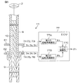
図5は、トルクセンサ11の構成を図解的に示す模式図である。
The current
FIG. 5 is a schematic diagram schematically showing the configuration of the
入力軸8には、環状の第1の磁石(多極磁石)61が一体回転可能に連結されている。第1の磁石61の下側には、第1の磁石61の回転に応じて互いに位相差を有する正弦波状の信号をそれぞれ出力する3つの磁気センサ71,72,73が配置されている。
出力軸9には、環状の第2の磁石(多極磁石)62が一体回転可能に連結されている。第2の磁石62の上側には、第2の磁石62の回転に応じて互いに位相差を有する正弦波状の信号をそれぞれ出力する3つの磁気センサ74,75,76が配置されている。
An annular first magnet (multipolar magnet) 61 is connected to the
An annular second magnet (multipolar magnet) 62 is connected to the
各磁気センサ71〜76の出力信号S1〜S6は、入力軸8に加えられる操舵トルクを演算するためのトルク演算用ECU77に入力されている。トルク演算用ECU77の電源は、イグニッションキーがオン操作されることによってオンとなる。イグニッションキーがオフ操作されたときには、そのことを示すイグニッションキーオフ操作信号が、トルク演算用ECU77に入力される。なお、磁気センサとしては、たとえば、ホール素子、磁気抵抗素子(MR素子)等、磁界の作用により電気的特性が変化する特性を有する素子を備えたものを用いることができる。この実施形態では、磁気センサとしては、ホール素子が用いられている。
Output signals S 1 to S 6 of the
前記磁石61,62、前記磁気センサ71〜76およびトルク演算用ECU77によって、トルクセンサ11が構成されている。
トルク演算用ECU77は、マイクロコンピュータを含んでいる。マイクロコンピュータは、CPUおよびメモリ(ROM,RAM,不揮発性メモリ等)を備えており、所定のプログラムを実行することによって、複数の機能処理部として機能する。この複数の機能処理部には、第1の回転角演算部77Aと、第2の回転角演算部77Bと、トルク演算部77Cとを含んでいる。
The
The
第1の回転角演算部77Aは、3つの磁気センサ71,72,73の出力信号S1,S2,S3に基づいて入力軸8の回転角(電気角θA)を演算する。第2の回転角演算部77Bは、3つの磁気センサ74,75,73の出力信号S4,S5,S6に基づいて出力軸9の回転角(電気角θB)を演算する。
トルク演算部77Cは、第1の回転角演算部77Aによって検出された入力軸8の回転角θAと第2の回転角演算部77Bによって検出された出力軸9の回転角θBとに基づいて、入力軸8に加えられた操舵トルクThを演算する。具体的には、操舵トルクThは、トーションバー10のバネ定数をKとし、各磁石61,62に設けられた磁極対数をNとすると、次式(1)に基づいて演算される。
The first
The
Th={(θA−θB)/N}×K …(1)
第1の磁石61、磁気センサ71,72,73および第1の回転角演算部77Aによって、入力軸8の回転角θAを検出するための第1の回転角検出装置が構成されている。また、第2の磁石62、磁気センサ74,75,76および第2の回転角演算部77Bによって、出力軸9の回転角θBを検出するための第2の回転角検出装置が構成されている。第1の回転角検出装置(第1の回転角演算部77A)の動作と第2の回転角検出装置(第2の回転角演算部77B)動作は同様であるので、以下、第1の回転角検出装置(第1の回転角演算部77A)の動作についてのみ説明する。
Th = {(θ A −θ B ) / N} × K (1)
図6は、第1の磁石61の構成および2つの磁気センサの配置を示す模式図である。
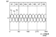
第1の磁石61は、周方向に等角度間隔で配された4組の磁極対(M1,M2),(M3,M4),(M5,M6),(M7,M8)を有している。つまり、第1の磁石61は、等角度間隔で配置された8個の磁極M1〜M8を有している。各磁極M1〜M8は、入力軸8の中心軸を中心として、ほぼ45°(電気角ではほぼ180°)の角度間隔(角度幅)で配置されている。各磁極M1〜M8の磁力の大きさは、ほぼ一定である。
FIG. 6 is a schematic diagram showing the configuration of the
The
3つの磁気センサ71,72,73は、第1の磁石61の下側の環状端面に対向して、配置されている。以下において、磁気センサ71を第1磁気センサ71、磁気センサ72を第2磁気センサ72、磁気センサ73を第3磁気センサ73という場合がある。第1磁気センサ71と第2磁気センサ72とは、入力軸8の中心軸を中心として電気角で120°の角度間隔で配置されている。また、第2磁気センサ72と第3磁気センサ73とは、入力軸8の中心軸を中心として電気角で120°の角度間隔で配置されている。したがって、第1磁気センサ71と第3磁気センサ73とは、入力軸8の中心軸を中心として電気角で240°の角度間隔で配置されている。
The three
図6に矢印で示す方向を入力軸8の正方向の回転方向とする。そして、入力軸8が正方向に回転されると入力軸8の回転角が大きくなり、入力軸8が逆方向に回転されると、入力軸2の回転角が小さくなるものとする。各磁気センサ71,72,73からは、図7に示すように、入力軸8の回転に伴って、正弦波状の信号S1,S2,S3が出力される。なお、図6の横軸の回転角[deg]は、機械角を表している。
A direction indicated by an arrow in FIG. 6 is a positive rotation direction of the
以下において、第1磁気センサ71の出力信号S1を第1出力信号S1または第1センサ値S1といい、第2磁気センサ72の出力信号S2を第2出力信号S2または第2センサ値S2といい、第3磁気センサ73の出力信号S3を第3出力信号S3または第3センサ値S3という場合がある。
以下においては、説明の便宜上、入力軸8の回転角をθAではなく、θで表すことにする。各出力信号S1,S2,S3が正弦波信号であるとみなし、入力軸8の回転角をθ(電気角)とすると、第1磁気センサ71の出力信号S1は、S1=A1・sinθと表され、第2磁気センサ72の出力信号S2は、S2=A2・sin(θ+120)と表され、第3磁気センサ73の出力信号S3は、S3=A3・sin(θ+240)と表される。A1,A2,A3は、それぞれ振幅を表している。第1出力信号S1と第2出力信号S2との位相差は120度である。第2出力信号S2と第3出力信号S3との位相差も120度である。したがって、第1出力信号S1と第3出力信号S3との位相差は240度である。
In the following, the output signals S 1 is referred to as a first output signals S 1 or the first sensor value S 1, the output signal S 2 of the second
In the following, for convenience of explanation, the rotation angle of the
第1の回転角演算部77Aによる回転角θの演算方法の基本的な考え方について説明する。第1の回転角演算部77Aによる回転角演算モードには、第1演算モード〜第5演算モードがある。以下、各演算モードについて説明する。
[1]第1演算モード
第1演算モードは、第1および第2磁気センサ71,72が、3サンプリング周期(3演算周期)連続して共に同じ1つの磁極を検出している場合に適用される演算モードである。第1演算モードでは、第1および第2磁気センサ71,72における3サンプリング分の出力信号に基づいて回転角θが演算される。
The basic concept of the calculation method of the rotation angle θ by the first rotation
[1] First Calculation Mode The first calculation mode is applied when the first and second
第1出力信号S1と第2出力信号S2との位相差(電気角)をCで表すことにする。また、今回のサンプリング周期の番号(今回の演算周期の番号)を[n]、前回のサンプリング周期の番号を[n-1]、前々回のサンプリング周期の番号を[n-2]で表すことにする。また、各磁極M1〜M8の角度幅(磁極幅,ピッチ幅)のばらつきに基づく回転角演算誤差を補正するための補正値を、角度幅誤差補正値(磁極幅誤差補正値)といい、Eで表すことにする。 Phase difference between the first output signals S 1 and the second output signal S 2 (electrical angle) to be represented by C. In addition, the number of the current sampling cycle (the number of the current calculation cycle) is represented by [n], the number of the previous sampling cycle is represented by [n-1], and the number of the previous sampling cycle is represented by [n-2]. To do. A correction value for correcting a rotation angle calculation error based on variations in the angle widths (magnetic pole width and pitch width) of the magnetic poles M1 to M8 is referred to as an angular width error correction value (magnetic pole width error correction value). It will be expressed as
位相差C、サンプリング周期番号[n],[n-1],[n-2]および角度幅誤差補正値Eを用いると、今回、前回および前々回にサンプリングされた第1出力信号S1ならびに今回、前回および前々回にサンプリングされた第2出力信号S2を、それぞれ次式(2a),(2b),(2c), (2d),(2e),(2f)で表すことができる。
S1[n]=A1[n]sin(E1[n]θ[n]) …(2a)
S1[n-1]=A1[n-1]sin(E1[n-1]θ[n-1]) …(2b)
S1[n-2]=A1[n-2]sin(E1[n-2]θ[n-2]) …(2c)
S2[n]=A2[n]sin(E2[n]θ[n]+C) …(2d)
S2[n-1]=A2[n-1]sin(E2[n-1]θ[n-1]+C) …(2e)
S2[n-2]=A2[n-2]sin(E2[n-2]θ[n-2]+C) …(2f)
前記式(2a)〜(2f)において、E1[x]は、x番目の演算周期において第1磁気センサ71が検出している磁極に対応する角度幅誤差補正値である。E2[x]は、x番目の演算周期において第2磁気センサ72が検出している磁極に対応する角度幅誤差補正値である。
Phase difference C, the sampling period number [n], [n-1 ], the use of [n-2] and angular width error correction value E, this first output signals S 1 and the current sampled the last and second last , the second output signal S 2 which is sampled last and second last, the following equations (2a), can be expressed by (2b), (2c), (2d), (2e), (2f).
S 1 [n] = A 1 [n] sin (E 1 [n] θ [n]) (2a)
S 1 [n-1] = A 1 [n-1] sin (E 1 [n-1] θ [n-1]) (2b)
S 1 [n-2] = A 1 [n-2] sin (E 1 [n-2] θ [n-2]) (2c)
S 2 [n] = A 2 [n] sin (E 2 [n] θ [n] + C) (2d)
S 2 [n-1] = A 2 [n-1] sin (E 2 [n-1] θ [n-1] + C) ... (2e)
S 2 [n-2] = A 2 [n-2] sin (E 2 [n-2] θ [n-2] + C) (2f)
In the equations (2a) to (2f), E 1 [x] is an angle width error correction value corresponding to the magnetic pole detected by the first
ある磁極の角度幅をw(電気角)とすると、その磁極の角度幅誤差θerr(電気角)は、次式(3)で定義される。
θerr=w−180 …(3)
その磁極に対する角度幅誤差補正値Eは、次式(4)で定義される。
E=180/w
=180/(θerr+180) …(4)
各磁極の角度幅誤差補正値Eは、各磁極の磁極幅に関する情報である。なお、各磁極の磁極幅に関する情報は、各磁極の角度幅wであってもよいし、各磁極の角度幅誤差θerrであってもよい。
When the angular width of a certain magnetic pole is w (electrical angle), the angular width error θ err (electrical angle) of the magnetic pole is defined by the following equation (3).
θ err = w−180 (3)
The angular width error correction value E for the magnetic pole is defined by the following equation (4).
E = 180 / w
= 180 / (θ err +180) (4)
The angle width error correction value E of each magnetic pole is information regarding the magnetic pole width of each magnetic pole. The information on the magnetic pole width of each magnetic pole may be the angular width w of each magnetic pole or the angular width error θ err of each magnetic pole.
Cが既知であるとすると、前記式(2a)〜(2f)で表される6つの式に含まれる未知数の数は16となる。つまり、未知数の数が方程式の数より多いため、このままでは、6つの式からなる連立方程式を解くことができない。
この実施形態では、サンプリング間隔(サンプリング周期)を短く設定することにより、3サンプリング間の温度変化による振幅の変化がないとみなす。つまり、3サンプリング間の第1磁気センサ71の出力信号の振幅A1[n],A1[n-1],A1[n-2]が互いに等しいとみなして、これらをA1とする。同様に、3サンプリング間の第2磁気センサ72の出力信号の振幅A2[n],A2[n-1],A2[n-2]が互いに等しいとみなし、これらをA2とする。
Assuming that C is known, the number of unknowns included in the six expressions represented by the expressions (2a) to (2f) is 16. In other words, since the number of unknowns is larger than the number of equations, it is not possible to solve simultaneous equations consisting of six equations.
In this embodiment, by setting the sampling interval (sampling period) to be short, it is considered that there is no change in amplitude due to a temperature change between three samplings. That is, it is assumed that the amplitudes A 1 [n], A 1 [n−1], and A 1 [n−2] of the output signal of the first
3サンプリング間において、両磁気センサ71,72が共に同じ1つの磁極を検出している場合には、3サンプリング分の両磁気センサ71,72の出力信号に含まれている角度幅誤差補正値E1[n],E1[n-1],E1[n-2],E2[n],E2[n-1],E2[n-2]は同じ値となるので、これらをEで表すことにする。これにより、前記式(2a)〜(2f)は、それぞれ次式(5a)〜(5f)で表わされる。
When both
S1[n]=A1sin(Eθ[n]) …(5a)
S1[n-1]=A1sin(Eθ[n-1]) …(5b)
S1[n-2]=A1sin(Eθ[n-2]) …(5c)
S2[n]=A2sin(Eθ[n]+C) …(5d)
S2[n-1]=A2sin(Eθ[n-1]+C) …(5e)
S2[n-2]=A2sin(Eθ[n-2]+C) …(5f)
これら6つの式に含まれる未知数(A1,A2,E,θ[n],θ[n-1],θ[n-2])の数は6となる。つまり、未知数の数が方程式の数以下となるため、6つの式からなる連立方程式を解くことができる。したがって、前記6つの式(5a)〜(5f) からなる連立方程式を解くことにより、入力軸8の回転角θ[n]を演算することができる。
S 1 [n] = A 1 sin (Eθ [n]) (5a)
S 1 [n-1] = A 1 sin (Eθ [n-1]) (5b)
S 1 [n-2] = A 1 sin (Eθ [n-2]) (5c)
S 2 [n] = A 2 sin (Eθ [n] + C) (5d)
S 2 [n-1] = A 2 sin (Eθ [n-1] + C) (5e)
S 2 [n-2] = A 2 sin (Eθ [n-2] + C) (5f)
The number of unknowns (A 1 , A 2 , E, θ [n], θ [n−1], θ [n−2]) included in these six formulas is 6. That is, since the number of unknowns is less than or equal to the number of equations, simultaneous equations composed of six equations can be solved. Therefore, the rotation angle θ [n] of the
以下、両磁気センサ間の位相差Cが120度である場合について、具体的に説明する。位相差Cが120度である場合には、前記6つの式(5a)〜(5f) は、それぞれ次式(6a)〜(6f)で表わすことができる。
S1[n]=A1sin(Eθ[n]) …(6a)
S1[n-1]=A1sin(Eθ[n-1]) …(6b)
S1[n-2]=A1sin(Eθ[n-2]) …(6c)
S2[n]=A2sin(Eθ[n]+120) …(6d)
S2[n-1]=A2sin(Eθ[n-1]+120) …(6e)
S2[n-2]=A2sin(Eθ[n-2]+120) …(6f)
Eθ[n]を1つの未知数と考えると、前記6つの式(6a)〜(6f)のうちの4つの式(6a),(6b),(6d),(6e) からなる連立方程式を解くことにより、Eθ[n]は、次式(7) (以下、「Eθ基本演算式(7)」という。)で表わされる。
Hereinafter, the case where the phase difference C between the two magnetic sensors is 120 degrees will be specifically described. When the phase difference C is 120 degrees, the six equations (5a) to (5f) can be expressed by the following equations (6a) to (6f), respectively.
S 1 [n] = A 1 sin (Eθ [n]) (6a)
S 1 [n-1] = A 1 sin (Eθ [n-1]) (6b)
S 1 [n-2] = A 1 sin (Eθ [n-2]) (6c)
S 2 [n] = A 2 sin (Eθ [n] +120) (6d)
S 2 [n-1] = A 2 sin (Eθ [n-1] +120) (6e)
S 2 [n-2] = A 2 sin (Eθ [n-2] +120) (6f)
Considering Eθ [n] as one unknown, solve the simultaneous equations consisting of the four equations (6a), (6b), (6d), and (6e) among the six equations (6a) to (6f). Thus, Eθ [n] is expressed by the following equation (7) (hereinafter referred to as “Eθ basic operation equation (7)”).

また、前記6つの式(6a)〜(6f)からなる連立方程式を解くことにより、角度幅誤差補正値Eは、次式(8) (以下、「E演算式(8)」という。)で表わされる。 Further, by solving the simultaneous equations consisting of the above six formulas (6a) to (6f), the angular width error correction value E is expressed by the following formula (8) (hereinafter referred to as “E calculation formula (8)”). Represented.
したがって、前記Eθ基本演算式(7)により演算されたEθ[n]を、前記E演算式(8)により演算された角度幅誤差補正値Eで除することにより、θ[n]を求めることができる。つまり、次式(9)により、θ[n]を求めることができる。
θ[n]=Eθ[n]/E …(9)
ただし、E演算式(8) に含まれている分数のいずれかの分母が零になる場合には、E演算式(8)に基づいて角度幅誤差補正値Eを演算することはできない。そこで、この実施形態では、E演算式(8) に含まれている分数のいずれかの分母が零になる場合には、前回に演算された角度幅誤差補正値Eを今回の角度幅誤差補正値Eとして用いるようにしている。
Therefore, θ [n] is obtained by dividing Eθ [n] calculated by the Eθ basic calculation formula (7) by the angle width error correction value E calculated by the E calculation formula (8). Can do. That is, θ [n] can be obtained by the following equation (9).
θ [n] = Eθ [n] / E (9)
However, when any denominator of the fraction contained in E calculation formula (8) becomes zero, the angle width error correction value E cannot be calculated based on E calculation formula (8). Therefore, in this embodiment, when any denominator of the fraction included in E arithmetic expression (8) becomes zero, the angle width error correction value E calculated last time is used as the current angle width error correction. The value E is used.
なお、E演算式(8) に含まれている分数のいずれかの分母が零になる場合とは、次式(10),(11),(12)でそれぞれ表される3つの条件のうちの少なくとも1つの条件を満たす場合である。 Note that the case where any denominator of the fraction contained in E equation (8) is zero is one of the three conditions expressed by the following equations (10), (11), and (12): This is a case where at least one of the following conditions is satisfied.
また、Eθ基本演算式(7)に含まれている分数のいずれかの分母が零になる場合には、Eθ基本演算式(7)に基づいてEθ[n]を演算することはできない。そこで、この実施形態では、Eθ基本演算式(7)に含まれている分数のいずれかの分母が零になる場合には、Eθ基本演算式(7)とは異なる演算式によってEθ[n]を演算するようにしている。さらに、この実施形態では、Eθ基本演算式(7)に基づいてEθ[n]を演算することができるけれども、より簡単な演算式によってEθ[n]を演算できる場合には、Eθ基本演算式(7)とは異なる演算式によってEθ[n]を演算するようにしている。この実施形態では、Eθ基本演算式(7)よりも簡単にEθ[n]を演算できる場合とは、S2[n]=0の場合またはS1[n]=0の場合である。 Further, when any denominator of the fraction included in the Eθ basic calculation formula (7) is zero, Eθ [n] cannot be calculated based on the Eθ basic calculation formula (7). Therefore, in this embodiment, when any denominator of the fraction included in the Eθ basic arithmetic expression (7) becomes zero, Eθ [n] is calculated by an arithmetic expression different from the Eθ basic arithmetic expression (7). Is calculated. Furthermore, in this embodiment, Eθ [n] can be calculated based on the Eθ basic calculation formula (7). However, when Eθ [n] can be calculated using a simpler calculation formula, the Eθ basic calculation formula is used. Eθ [n] is calculated by an arithmetic expression different from (7). In this embodiment, the case where Eθ [n] can be calculated more easily than the Eθ basic calculation formula (7) is the case where S 2 [n] = 0 or S 1 [n] = 0.
この実施形態では、Eθ[n]を演算するための演算式として、Eθ基本演算式(7)を含めて10種類の演算式が用意されている。表1は、10種類の演算式と、その演算式が適用される条件とを示している。なお、Eθ[n]を演算する際には、表1の上から順番にその条件を満たしているか否かが判別され、条件を満たしたと判別されるとそれ以降の条件判別は行われず、当該条件に対応する演算式により、Eθ[n]が演算される。 In this embodiment, 10 types of calculation formulas including Eθ basic calculation formula (7) are prepared as calculation formulas for calculating Eθ [n]. Table 1 shows ten types of arithmetic expressions and conditions to which the arithmetic expressions are applied. When calculating Eθ [n], it is determined whether or not the condition is satisfied in order from the top of Table 1. If it is determined that the condition is satisfied, the subsequent condition determination is not performed. Eθ [n] is calculated by an arithmetic expression corresponding to the condition.
表1の上から1番目の演算式は、Eθ基本演算式(7)である。Eθ基本演算式(7)は、S1[n]およびS2[n]のいずれもが零でなく、かつEθ基本演算式(7)に含まれている分数のいずれの分母も零でないという条件を満たしている場合に、適用される。Eθ基本演算式(7)に含まれている分数のいずれの分母も零でないという条件は、p1−p2≠0でかつ、p1 2+p1p2+p2 2≠0でかつ、S1[n-1]≠0でかつS2[n-1]≠0である場合に満たされる。なお、S1[n-1]はp1の分母であり、S2[n-1]はp2の分母である。 The first arithmetic expression from the top of Table 1 is the Eθ basic arithmetic expression (7). In Eθ basic arithmetic expression (7), neither S 1 [n] nor S 2 [n] is zero, and any denominator of a fraction contained in Eθ basic arithmetic expression (7) is not zero. Applicable when conditions are met. The condition that any denominator of the fraction included in the Eθ basic arithmetic expression (7) is not zero is that p 1 −p 2 ≠ 0, p 1 2 + p 1 p 2 + p 2 2 ≠ 0, and S It is satisfied when 1 [n-1] ≠ 0 and S 2 [n-1] ≠ 0. Note that S 1 [n-1] is the denominator of p 1 and S 2 [n-1] is the denominator of p 2 .
ただし、p1 2+p1p2+p2 2=0が成立するのは、p1=p2=0の場合だけであるが、第1磁気センサ71と第2磁気センサ72とは位相が120度ずれているため、両磁気センサ71,72のセンサ値S1,S2が同時に零になることはない。このため、p1 2+p1p2+p2 2=0が成立することはない。したがって、Eθ基本演算式(7)に含まれている分数のいずれの分母も零でないという条件は、p1−p2≠0でかつ、S1[n-1]≠0でかつS2[n-1]≠0である場合に満たされる。
However, p 1 2 + p 1 p 2 + p 2 2 = 0 holds only when p 1 = p 2 = 0, but the phase of the first
表1の上から2番目の演算式は、p1−p2=0である場合に適用される演算式である。p1−p2=0が成立する場合について検討する。この場合には、p1=p2であるから、次式(13)が成立する。 The second arithmetic expression from the top of Table 1 is an arithmetic expression applied when p 1 −p 2 = 0. Consider the case where p 1 −p 2 = 0 holds. In this case, since p 1 = p 2 , the following equation (13) is established.
これを変形すると、次式(14)が得られる。 When this is modified, the following equation (14) is obtained.
前記式(14)が成立する場合とは、Eθ[n]とEθ[n-1]とが等しい場合である。つまり、今回のEθ[n]が前回のEθ[n-1]に等しい場合である。そこで、S1[n]およびS2[n]のいずれもが零でなく、かつp1の分母S1[n-1]およびp2の分母S2[n-1]のいずれもが零でなく、かつp1−p2=0であるという条件を満たした場合には、前回に演算されたEθ[n-1]が今回のEθ[n]として用いられる。 The case where the formula (14) is satisfied is a case where Eθ [n] and Eθ [n−1] are equal. That is, the current Eθ [n] is equal to the previous Eθ [n−1]. Therefore, none of the S 1 [n] and S 2 [n] is not zero, and none of the denominator S 1 of p 1 [n-1] and the denominator S 2 [n-1] of p 2 is zero If the condition that p 1 −p 2 = 0 is satisfied, Eθ [n−1] calculated last time is used as the current Eθ [n].
表1の上から3番目および4番目の演算式は、p1の分母S1[n-1]が零となる場合に適用される演算式である。S1[n-1]=A1sinEθ[n-1]であるので、sinEθ[n-1]=0のときに、S1[n-1]=0となる。つまり、Eθ[n-1]が0度または180度のときに、S1[n-1]が零となる。S2[n-1]=A2sin(Eθ[n-1]+120)であるので、Eθ[n-1]が0度のときにはS2[n-1]>0となり、Eθ[n-1]が180度のときにはS2[n-1]<0となる。したがって、S1[n-1]=0でかつS2[n-1]>0のときにはEθ[n-1]=0となり、S1[n-1]=0でかつS2[n-1]<0のときにはEθ[n-1]=180となる。 The third and fourth arithmetic expressions from the top of Table 1 are arithmetic expressions applied when the denominator S 1 [n−1] of p 1 becomes zero. Since S 1 [n-1] = A 1 sinEθ [n-1], when sinEθ [n-1] = 0, S 1 [n-1] = 0. That is, when Eθ [n−1] is 0 degree or 180 degrees, S 1 [n−1] is zero. Since S 2 [n-1] = A 2 sin (Eθ [n-1] +120), when Eθ [n-1] is 0 degree, S 2 [n-1]> 0, and Eθ [n− When 1] is 180 degrees, S 2 [n−1] <0. Therefore, when S 1 [n-1] = 0 and S 2 [n-1]> 0, Eθ [n-1] = 0, and S 1 [n-1] = 0 and S 2 [n− When 1] <0, Eθ [n−1] = 180.
Eθ[n-1]=0である場合には、前記式 (6c),(6d)は、それぞれ次式 (15c),(15d)で表される。
S2[n]=A2sin(Eθ[n]+120) …(15c)
S2[n-1]=A2sin120=√3/2・A2 …(15d)
前記式(15d)から、次式(16)が得られる。
When Eθ [n−1] = 0, the equations (6c) and (6d) are represented by the following equations (15c) and (15d), respectively.
S 2 [n] = A 2 sin (Eθ [n] +120) (15c)
S 2 [n-1] = A 2
From the equation (15d), the following equation (16) is obtained.
A2=(2/√3)・S2[n-1] …(16)
前記式(16)を前記式(15c)に代入すると、次式(17)が得られる。
sin(Eθ[n]+120)=(√3/2)・(S2[n]/S2[n-1]) …(17)
したがって、Eθ[n]は、次式(18)により演算することができる。
A 2 = (2 / √3) · S 2 [n-1] (16)
Substituting Equation (16) into Equation (15c) yields Equation (17) below.
sin (Eθ [n] +120) = (√3 / 2) · (S 2 [n] / S 2 [n−1]) (17)
Therefore, Eθ [n] can be calculated by the following equation (18).
つまり、表1の上から3番目に示すように、S1[n]およびS2[n]のいずれもが零でなく、かつp2の分母S2[n-1]が零でなく、かつp1の分母S1[n-1]が零であり、かつS2[n-1]>0であるという条件を満たした場合には、前記式(18)で表される演算式に基づいてEθ[n]が演算される。
一方、Eθ[n-1]=180である場合には、前記式 (6c),(6d)は、それぞれ次式(19c),(19d)で表される。
That is, as shown third from the top in Table 1, neither S 1 [n] nor S 2 [n] is zero and the denominator S 2 [n−1] of p 2 is not zero. When the condition that the denominator S 1 [n-1] of p 1 is zero and S 2 [n-1]> 0 is satisfied, the arithmetic expression represented by the above equation (18) is obtained. Based on this, Eθ [n] is calculated.
On the other hand, when Eθ [n−1] = 180, the equations (6c) and (6d) are expressed by the following equations (19c) and (19d), respectively.
S2[n]=A2sin(Eθ[n]+120) …(19c)
S2[n-1]=A2sin300=−√3/2・ A2 …(19d)
前記式(19d)から、次式(20)が得られる。
A2=(−2/√3)・S2[n-1] …(20)
前記式(20)を前記式(19c)に代入すると、次式(21)が得られる。
S 2 [n] = A 2 sin (Eθ [n] +120) (19c)
S 2 [n-1] = A 2 sin 300 = −√3 / 2 · A 2 (19d)
From the equation (19d), the following equation (20) is obtained.
A 2 = (− 2 / √3) · S 2 [n−1] (20)
Substituting the equation (20) into the equation (19c) yields the following equation (21).
sin(Eθ[n]+120)=(−√3/2)・(S2[n]/S2[n-1]) …(21)
したがって、Eθ[n]は、次式(22)により演算することができる。
sin (Eθ [n] +120) = (− √3 / 2) · (S 2 [n] / S 2 [n−1]) (21)
Therefore, Eθ [n] can be calculated by the following equation (22).
つまり、表1の上から4番目に示すように、S1[n]およびS2[n]のいずれもが零でなく、かつp2の分母S2[n-1]が零でなく、かつp1の分母S1[n-1]が零であり、かつS2[n-1]<0であるという条件を満たした場合には、前記式(22)で表される演算式に基づいてEθ[n]が演算される。
表1の上から5番目および6番目の演算式は、S2[n]=0となる場合に適用される演算式である。S2[n]=A2sin(Eθ[n]+120)であるので、sin(Eθ[n]+120)=0のときに、S2[n]=0となる。つまり、Eθ[n]が−120度または60度のときに、S2[n]=0となる。S1[n]=A1sinEθ[n]であるので、Eθ[n]が−120度のときにはS1[n]<0となり、Eθ[n]が60度のときにはS1[n]>0となる。したがって、S2[n]=0でかつS1[n]>0のときにはEθ[n]=60となり、S2[n]=0でかつS1[n]<0であればEθ[n]=−120となる。
That is, as shown in the fourth from the top of Table 1, neither S 1 [n] nor S 2 [n] is zero and the denominator S 2 [n−1] of p 2 is not zero. When the condition that the denominator S 1 [n-1] of p 1 is zero and S 2 [n-1] <0 is satisfied, the arithmetic expression represented by the above equation (22) is satisfied. Based on this, Eθ [n] is calculated.
The fifth and sixth arithmetic expressions from the top of Table 1 are arithmetic expressions applied when S 2 [n] = 0. Since S 2 [n] = A 2 sin (Eθ [n] +120), when sin (Eθ [n] +120) = 0, S 2 [n] = 0. That is, S 2 [n] = 0 when Eθ [n] is −120 degrees or 60 degrees. Since S 1 [n] = A 1 sin Eθ [n], S 1 [n] <0 when Eθ [n] is −120 degrees, and S 1 [n]> when Eθ [n] is 60 degrees. 0. Therefore, Eθ [n] = 60 when S 2 [n] = 0 and S 1 [n]> 0, and Eθ [n] when S 2 [n] = 0 and S 1 [n] <0. ] = − 120.
つまり、表1の上から5番目に示すように、S1[n]が零でなく、かつp2の分母S2[n-1]が零でなく、かつS2[n]=0であり、かつS1[n]>0であるという条件を満たした場合には、Eθ[n]は60度として演算される。また、表1の上から6番目に示すように、S1[n]が零でなく、かつp2の分母S2[n-1]が零でなく、かつS2[n]=0であり、かつS1[n]>0であるという条件を満たした場合には、Eθ[n]は−120度として演算される。 That is, as shown fifth from the top in Table 1, S 1 [n] is not zero, the denominator S 2 [n−1] of p 2 is not zero, and S 2 [n] = 0. If there is a condition that S 1 [n]> 0, Eθ [n] is calculated as 60 degrees. Further, as shown in Table 6 from the top, S 1 [n] is not zero, the denominator S 2 [n−1] of p 2 is not zero, and S 2 [n] = 0. If the condition that S 1 [n]> 0 is satisfied, Eθ [n] is calculated as −120 degrees.
表1の上から7番目および8番目の演算式は、p2の分母S2[n-1]が零となる場合に適用される演算式である。S2[n-1]=A2sin(Eθ[n-1]+120)であるので、sin(Eθ[n-1]+120)=0のときに、S2[n-1]=0となる。つまり、Eθ[n-1]が−120度または60度のときに、S2[n-1]が零となる。S1[n-1]=A1sinEθ[n-1]であるので、Eθ[n-1]が−120度のときにはS1[n-1]<0となり、Eθ[n-1]が60度のときにはS1[n-1]>0となる。したがって、S2[n-1]=0でかつS1[n-1]>0のときにはEθ[n-1]=60となり、S2[n-1]=0でかつS1[n-1]<0のときにはEθ[n-1]=−120となる。 The seventh and eighth arithmetic expressions from the top of Table 1 are arithmetic expressions applied when the denominator S 2 [n−1] of p 2 is zero. Since S 2 [n-1] = A 2 sin (Eθ [n-1] +120), when sin (Eθ [n-1] +120) = 0, S 2 [n-1] = 0 Become. That is, when Eθ [n−1] is −120 degrees or 60 degrees, S 2 [n−1] is zero. Since S 1 [n-1] = A 1 sinEθ [n-1], when Eθ [n-1] is −120 degrees, S 1 [n-1] <0, and Eθ [n-1] is When it is 60 degrees, S 1 [n-1]> 0. Therefore, when S 2 [n-1] = 0 and S 1 [n-1]> 0, Eθ [n-1] = 60, S 2 [n-1] = 0 and S 1 [n− When 1] <0, Eθ [n−1] = − 120.
Eθ[n-1]=60である場合には、前記式 (6a),(6b)は、それぞれ次式 (23a),(23b)で表される。
S1[n]=A1sinEθ[n] …(23a)
S1[n-1]=A1sin60=√3/2・ A1 …(23b)
前記式(23b)から、次式(24)が得られる。
When Eθ [n−1] = 60, the equations (6a) and (6b) are represented by the following equations (23a) and (23b), respectively.
S 1 [n] = A 1 sin Eθ [n] (23a)
S 1 [n-1] = A 1 sin 60 = √3 / 2 · A 1 (23b)
From the equation (23b), the following equation (24) is obtained.
A1=(2/√3)・S1[n-1] …(24)
前記式(24)を前記式(23a)に代入すると、次式(25)が得られる。
sinEθ[n]=(√3/2)・(S1[n]/S1[n-1]) …(25)
したがって、Eθ[n]は、次式(26)により演算することができる。
A 1 = (2 / √3) · S 1 [n-1] (24)
Substituting the equation (24) into the equation (23a) yields the following equation (25).
sinEθ [n] = (√3 / 2) · (S 1 [n] / S 1 [n-1]) (25)
Therefore, Eθ [n] can be calculated by the following equation (26).
つまり、表1の上から7番目に示すように、S1[n]が零でなく、かつp2の分母S2[n-1]が零であり、かつS1[n-1]>0であるという条件を満たした場合には、前記式(26)で表される演算式に基づいてEθ[n]が演算される。
一方、Eθ[n-1]=−120である場合には、前記式 (6a),(6b)は、それぞれ次式 (27a),(27b)で表される。
That is, as shown in Table 7 from the top, S 1 [n] is not zero, the denominator S 2 [n-1] of p 2 is zero, and S 1 [n-1]> When the condition of 0 is satisfied, Eθ [n] is calculated based on the arithmetic expression expressed by the expression (26).
On the other hand, when Eθ [n−1] = − 120, the equations (6a) and (6b) are expressed by the following equations (27a) and (27b), respectively.
S1[n]=A1sinEθ[n] …(27a)
S1[n-1]=A1sin(−120)=−√3/2・ A2 …(27b)
前記式(27b)から、次式(28)が得られる。
A1=(−2/√3)・S1[n-1] …(28)
前記式(28)を前記式(27a)に代入すると、次式(29)が得られる。
S 1 [n] = A 1 sin Eθ [n] (27a)
S 1 [n-1] = A 1 sin (−120) = − √3 / 2 · A 2 (27b)
From the equation (27b), the following equation (28) is obtained.
A 1 = (− 2 / √3) · S 1 [n−1] (28)
Substituting the equation (28) into the equation (27a) yields the following equation (29).
sinEθ[n]=(−√3/2)・(S1[n]/S1[n-1]) …(29)
したがって、Eθ[n]は、次式(30)により演算することができる。
sinEθ [n] = (− √3 / 2) · (S 1 [n] / S 1 [n−1]) (29)
Therefore, Eθ [n] can be calculated by the following equation (30).
つまり、表1の上から8番目に示すように、S1[n]が零でなく、かつp2の分母S2[n-1]が零であり、かつS1[n-1]<0であるという条件を満たした場合には、前記式(30)で表される演算式に基づいてEθ[n]が演算される。
表1の上から9番目および10番目の演算式は、S1[n]=0となる場合に適用される演算式である。S1[n]=A1sinEθ[n]であるので、sinEθ[n]=0のときに、S1[n]=0となる。つまり、Eθ[n]が0度または180度のときに、S1[n]=0となる。S2[n]=A2sin(Eθ[n]+120]であるので、Eθ[n]が0度のときにはS2[n]>0となり、Eθ[n]が180度のときにはS2[n]<0となる。したがって、S1[n]=0でかつS2[n]>0であればEθ[n]=0となり、S1[n]=0でかつS2[n]<0であればEθ[n]=180となる。
That is, as shown in Table 8 from the top, S 1 [n] is not zero, the denominator S 2 [n−1] of p 2 is zero, and S 1 [n−1] < When the condition of 0 is satisfied, Eθ [n] is calculated based on the arithmetic expression expressed by the expression (30).
The ninth and tenth arithmetic expressions from the top of Table 1 are arithmetic expressions that are applied when S 1 [n] = 0. Since S 1 [n] = A 1 sinEθ [n], when sinEθ [n] = 0, S 1 [n] = 0. That is, when Eθ [n] is 0 degree or 180 degrees, S 1 [n] = 0. Since it is S 2 [n] = A 2 sin (Eθ [n] +120], Eθ [n] is S 2 [n] at the time of 0 degree> 0, E.theta [n] is at the time of 180 ° S 2 [ n] <0 Therefore, if S 1 [n] = 0 and S 2 [n]> 0, Eθ [n] = 0, and S 1 [n] = 0 and S 2 [n] If <0, Eθ [n] = 180.
つまり、表1の上から9番目に示すように、S1[n]が零であり、かつS2[n]>0であるという条件を満たした場合には、Eθ[n]は0度として演算される。また、表1の上から10番目に示すように、S1[n]が零であり、かつS2[n]<0であるという条件を満たした場合には、Eθ[n]は180度として演算される。
Eθ[n]が演算されると、前記式(6a)に基づいて振幅A1を演算することができるとともに、前記式(6d)に基づいて振幅A2を演算することができる。つまり、第1演算モードによって、E,θ[n],A1,A2を演算することができる。
[2]第2演算モード
第2演算モードは、第2および第3磁気センサ72,73が、3サンプリング周期(3演算周期)連続して共に同じ1つの磁極を検出している場合に適用される演算モードである。第2演算モードでは、第2および第3磁気センサ72,73における3サンプリング分の出力信号に基づいて回転角θが演算される。
That is, as shown in the ninth from the top in Table 1, when the condition that S 1 [n] is zero and S 2 [n]> 0 is satisfied, Eθ [n] is 0 degree. Is calculated as As shown in the tenth from the top in Table 1, when the condition that S 1 [n] is zero and S 2 [n] <0 is satisfied, Eθ [n] is 180 degrees. Is calculated as
When Eθ [n] is calculated, the amplitude A 1 can be calculated based on the equation (6a), and the amplitude A 2 can be calculated based on the equation (6d). That is, E, θ [n], A 1, A 2 can be calculated in the first calculation mode.
[2] Second Calculation Mode The second calculation mode is applied when the second and third
第2磁気センサ72および第3磁気センサ73の出力信号S2,S3を、角度幅誤差補正値Eを用いて表すと、第2磁気センサ72の出力信号S2[n]はS2[n]=A2・sin(E2θ[n]+120)で表され、第3磁気センサ73の出力信号S3[n]は、S3[n]=A3・sin(E3θ[n]+240)と表される。ここで、E3は、第3磁気センサ73が検出している磁極に対応する角度幅誤差補正値である。第2磁気センサ72および第3磁気センサ73が同じ磁極を検出している場合には、E2とE3とは等しいので、これらをEで表すと、第2磁気センサ72の出力信号S2[n]はS2[n]=A2・sin(Eθ[n]+120)で表され、第3磁気センサ73の出力信号S3[n]は、S3[n]=A3・sin(Eθ[n]+240)と表される。
When the output signals S 2 and S 3 of the second
(Eθ[n]+120)をEΘ[n]に置き換えると、第2出力信号S2[n]はS2[n]=A2・sinEΘ[n]で表され、第3出力信号S3[n]はS3[n]=A3・sin(EΘ[n]+120)で表わされる。したがって、第2出力信号S2と第3出力信号S3とを用い、前述した方法と同様な方法でEΘ[n]とEとを演算することができる。EΘ[n]=Eθ[n]+120であるので、θ[n]=(EΘ[n]−120)/Eである。したがって、θ[n]=(EΘ[n]−120)/Eの式に、演算されたEΘ[n]とEを代入することにより、入力軸8の回転角θ[n]を演算することができる。また、EΘ[n]が演算されると、振幅A2および振幅A3を演算することができる。つまり、第2演算モードによって、E,θ[n],A2,A3を演算することができる。
When (Eθ [n] +120) is replaced with EΘ [n], the second output signal S 2 [n] is represented by S 2 [n] = A 2 · sinEΘ [n], and the third output signal S 3 [ n] is represented by S 3 [n] = A 3 · sin (EΘ [n] +120). Therefore, EΘ [n] and E can be calculated using the second output signal S 2 and the third output signal S 3 in the same manner as described above. Since EΘ [n] = Eθ [n] +120, θ [n] = (EΘ [n] −120) / E. Therefore, the rotation angle θ [n] of the
第2演算モードによる回転角演算に用いられる3サンプリング分の第2および第3出力信号を、前記式(6a) 〜(6f)にならって次式(31a) 〜(31f)で表すと、EΘ基本演算式およびE演算式はそれぞれ次式(32) および(33)で表すことができる。
S2[n]=A2sin(Eθ[n]+120) …(31a)
S2[n-1]=A2sin(Eθ[n-1]+120) …(31b)
S2[n-2]=A2sin(Eθ[n-2]+120) …(31c)
S3[n]=A3sin(Eθ[n]+120) …(31d)
S3[n-1]=A3sin(Eθ[n-1]+120) …(31e)
S3[n-2]=A3sin(Eθ[n-2]+120) …(31f)
When the second and third output signals for three samplings used for the rotation angle calculation in the second calculation mode are expressed by the following equations (31a) to (31f) following the equations (6a) to (6f), EΘ The basic arithmetic expression and the E arithmetic expression can be expressed by the following expressions (32) and (33), respectively.
S 2 [n] = A 2 sin (Eθ [n] +120) (31a)
S 2 [n-1] = A 2 sin (Eθ [n-1] +120) (31b)
S 2 [n−2] = A 2 sin (Eθ [n−2] +120) (31c)
S 3 [n] = A 3 sin (Eθ [n] +120) (31d)
S 3 [n-1] = A 3 sin (Eθ [n-1] +120) (31e)
S 3 [n-2] = A 3 sin (Eθ [n-2] +120) (31f)
第1演算モードまたは第2演算モードでは、3つの磁気センサ71,72,73のうちの2つの磁気センサにおける3サンプリング分の出力信号に基づいて入力軸8の回転角θ[n]を演算しているので、精度の高い回転角を演算することが可能となる。また、第1演算モードまたは第2演算モードでは、入力軸8の回転角θ[n]の演算に用いられる数式の数が、これらの数式に含まれている本来の未知数の数より少なくても、入力軸8の回転角θ[n]を演算することができるので、入力軸8の回転角θ[n]を演算するために必要なセンサ値の数を少なくすることが可能となる。
In the first calculation mode or the second calculation mode, the rotation angle θ [n] of the
第1演算モードまたは第2演算モードでは、3サンプリング間での同じ磁気センサの出力信号の振幅が互いに等しいとみなしている。3サンプリング間での同じ磁気センサの出力信号の振幅は、温度変化の影響によって異なる値となる可能性がある。しかしながら、サンプリング間隔が小さい場合には、3サンプリング間の温度変化は非常に小さいので、3サンプリング間での同じ磁気センサの出力信号の振幅は等しいとみなすことができる。したがって、第1演算モードまたは第2演算モードでは、3サンプリング間での温度変化の影響による振幅のばらつきを補償することができる。また、第1演算モードまたは第2演算モードでは、回転角の演算に用いられている2つの磁気センサ間の振幅は、別々の未知数として扱っているので、それらの2つの磁気センサ間の温度特性のばらつきの影響を補償することができる。これにより、精度の高い回転角を検出することができる。 In the first calculation mode or the second calculation mode, the amplitudes of the output signals of the same magnetic sensor during three samplings are considered to be equal to each other. The amplitude of the output signal of the same magnetic sensor during three samplings may be different depending on the influence of temperature change. However, when the sampling interval is small, the temperature change between the three samplings is very small, so that the amplitude of the output signal of the same magnetic sensor during the three samplings can be regarded as equal. Therefore, in the first calculation mode or the second calculation mode, it is possible to compensate for the amplitude variation due to the temperature change between the three samplings. Further, in the first calculation mode or the second calculation mode, the amplitude between the two magnetic sensors used for calculating the rotation angle is treated as a separate unknown, and therefore the temperature characteristics between the two magnetic sensors. It is possible to compensate for the influence of variations in the above. Thereby, a highly accurate rotation angle can be detected.
また、第1演算モードまたは第2演算モードでは、磁石61の各磁極M1〜M8の角度幅(ピッチ幅)のばらつきを高い精度で補償できるので、誤差のより小さい回転角を検出することが可能となる。
[3]第3演算モード
第3演算モードは、第1演算モードおよび第2演算モードのいずれもが適用できない場合であって、第1磁気センサ71が検出している磁極に対応する角度幅誤差補正値E1および第1出力信号S1の振幅A1が第1演算モードによって既に演算されてメモリに記憶されている場合に適用される演算モードである。第3演算モードでは、主として第1磁気センサ71の出力信号S1に基づいて回転角θが演算される。
Further, in the first calculation mode or the second calculation mode, variations in the angular widths (pitch widths) of the magnetic poles M1 to M8 of the
[3] Third Calculation Mode The third calculation mode is a case where neither the first calculation mode nor the second calculation mode can be applied, and an angular width error corresponding to the magnetic pole detected by the first
たとえば、図8Aに示すように、磁石61(入力軸8)が矢印で示す方向に回転している場合において、第1および第2磁気センサ71,72が同じ磁極(この例ではM1)を検出している状態から、第2磁気センサ72の検出している磁極が変化した場合に、第3演算モードは適用される。
角度幅誤差補正値Eと今演算周期の番号nを用いると、今演算周期においてサンプリングされた第1磁気センサ71の出力信号S1は、次式(34)で表される。
For example, as shown in FIG. 8A, when the magnet 61 (input shaft 8) rotates in the direction indicated by the arrow, the first and second
With number n of the angular width error correction value E and calculation cycle, the output signals S 1 of the first
S1[n]=A1[n]sin(E1θ[n]) …(34)
E1は、第1磁気センサ71が検出している磁極に対応する角度幅誤差補正値である。
前記式(34)から回転角θ[n]は、次式(35)で表される。
θ[n]=(1/E1)sin−1(S1[n]/A1) …(35)
メモリに記憶されており、第1磁気センサ71が検出している磁極に対応するE1およびA1を、前記式(35)に代入することにより、θ[n]が演算される。ただし、式(35)によって回転角θ[n]を演算する場合には、2つの回転角θ[n]が演算されるので、いずれの回転角が実際の回転角であるかを判定する必要がある。この判定方法について、図9を参照して説明する。図9には、第1出力信号S1、第2出力信号S2および第3出力信号S3の1周期分の波形が示されている。図9の横軸の回転角[deg]は、電気角を表している。
S 1 [n] = A 1 [n] sin (E 1 θ [n]) (34)
E 1 is an angle width error correction value corresponding to the magnetic pole detected by the first
From the equation (34), the rotation angle θ [n] is expressed by the following equation (35).
θ [n] = (1 / E 1 ) sin −1 (S 1 [n] / A 1 ) (35)
By substituting E 1 and A 1 corresponding to the magnetic poles stored in the memory and detected by the first
図9に示すように、第1出力信号S1[n]がたとえば正の値である場合には、(1/E1)sin−1(S1[n]/A1)に対応する回転角θ[n]は、0度〜90度の領域R1内の回転角と、90度〜180度の領域R2内の回転角との2つの回転角となる。また、第1出力信号S1[n]がたとえば負の値である場合には、(1/E1)sin−1(S1[n]/A1)に対応する回転角θ[n]は、180度〜270度の領域U1内の回転角と、270度〜360度の領域U2内の回転角との2つの回転角となる。 As shown in FIG. 9, when the first output signal S 1 [n] has a positive value, for example, the rotation corresponding to (1 / E 1 ) sin −1 (S 1 [n] / A 1 ) The angle θ [n] is two rotation angles: a rotation angle in the region R1 of 0 to 90 degrees and a rotation angle in the region R2 of 90 to 180 degrees. Further, when the first output signal S 1 [n] is, for example, a negative value, the rotation angle θ [n] corresponding to (1 / E 1 ) sin −1 (S 1 [n] / A 1 ). Are two rotation angles: a rotation angle in the region U1 of 180 to 270 degrees and a rotation angle in the region U2 of 270 to 360 degrees.
この実施形態では、第1磁気センサ71以外の2つの磁気センサ72,73の出力信号S2,S3のいずれか一方に基づいて、前記式(35)によって演算される2つの回転角のうちのいずれが実際の回転角であるかが判定される。たとえば、第2出力信号S2[n]に基づいて、前記判定が行われる場合について説明する。第2出力信号S2の振幅A2の1/2を閾値a(a>0)とする。この閾値aは、たとえば、メモリに記憶されている第2出力信号S2の振幅A2であって、第1磁気センサ71が検出している磁極に対応する振幅A2に基づいて求めることができる。なお、第1出力信号S1の振幅A1の1/2を閾値a(a>0)としてもよい。
In this embodiment, based on one of the output signals S 2 and S 3 of the two
第2出力信号S2[n]がa以上のときに取り得る入力軸8の回転角θ[n]は、0度〜30度の範囲および270度〜360度の範囲である。第2出力信号S2[n]が−a未満のときに取り得る入力軸8の回転角θ[n]は、90度〜210度の範囲である。第2出力信号S2[n]が−a以上a未満のときに取り得る入力軸8の回転角θ[n]は、30度〜90度の範囲および210度〜270度の範囲である。
The rotation angle θ [n] of the
したがって、前記式(35)によって演算された2つの回転角のうち、いずれの回転角が実際の回転角であるかを、第2出力信号S2[n]に基づいて判定することができる。具体的には、第1出力信号S1[n]が正の値である場合には、第2出力信号S2[n]が−a以上であれば、前記式(35)によって演算された2つの回転角のうち領域R1内の回転角が実際の回転角であると判定される。一方、第2出力信号S2[n]が−a未満であれば、前記式(35)によって演算された2つの回転角のうち領域R2内の回転角が実際の回転角であると判定される。 Therefore, it can be determined based on the second output signal S 2 [n] which of the two rotation angles calculated by the equation (35) is the actual rotation angle. Specifically, when the first output signal S 1 [n] is a positive value, if the second output signal S 2 [n] is equal to or greater than −a, the calculation is performed according to the equation (35). Of the two rotation angles, the rotation angle in the region R1 is determined to be the actual rotation angle. On the other hand, if the second output signal S 2 [n] is less than −a, it is determined that the rotation angle in the region R2 is the actual rotation angle among the two rotation angles calculated by the equation (35). The
第1出力信号S1[n]が負の値である場合には、第2出力信号S2[n]がa未満であれば、前記式(35)によって演算された2つの回転角のうち領域U1内の回転角が実際の回転角であると判定される。一方、第2出力信号S2[n]がa以上であれば、前記式(35)によって演算された2つの回転角のうち領域U2内の回転角が実際の回転角であると判定される。
[4]第4演算モード
第4演算モードは、第1演算モードおよび第2演算モードのいずれもが適用できない場合であって、第2磁気センサ72が検出している磁極に対応する角度幅誤差補正値E2および第2出力信号S2の振幅A2が第1演算モードまたは第3演算モードによって既に演算されてメモリに記憶されている場合に適用される演算モードである。第4演算モードでは、主として第2磁気センサ72の出力信号S2に基づいて回転角θが演算される。
When the first output signal S 1 [n] is a negative value, if the second output signal S 2 [n] is less than a, the two rotation angles calculated by the equation (35) are used. It is determined that the rotation angle in the region U1 is an actual rotation angle. On the other hand, if the second output signal S 2 [n] is greater than or equal to a, it is determined that the rotation angle in the region U2 is the actual rotation angle among the two rotation angles calculated by the equation (35). .
[4] Fourth Calculation Mode The fourth calculation mode is a case where neither the first calculation mode nor the second calculation mode can be applied, and an angular width error corresponding to the magnetic pole detected by the second
たとえば、図8Bに示すように、磁石61(入力軸8)が矢印で示す方向に回転している場合において、第1および第2磁気センサ71,72が同じ磁極(この例ではM1)を検出している状態から、第1磁気センサ71が検出している磁極が変化した場合に、第4演算モードは適用される。
角度幅誤差補正値Eと今演算周期の番号nを用いると、今演算周期においてサンプリングされた第2磁気センサ72の出力信号S2は、次式 (36)で表される。
For example, as shown in FIG. 8B, when the magnet 61 (input shaft 8) rotates in the direction indicated by the arrow, the first and second
With number n of the angular width error correction value E and calculation cycle, the output signal S 2 of the second
S2[n]=A2[n]sin(E2θ[n]+120) …(36)
E2は、第2磁気センサ72が検出している磁極に対応する角度幅誤差補正値である。
前記式(36)から回転角θ[n]は、次式(37)で表される。
θ[n]=(1/E2){sin−1(S2[n]/A2)−120} …(37)
メモリに記憶されており、第2磁気センサ72が検出している磁極に対応するE2およびA2を、前記式(37)に代入することにより、θ[n]が演算される。
S 2 [n] = A 2 [n] sin (E 2 θ [n] +120) (36)
E 2 is an angle width error correction value corresponding to the magnetic pole detected by the second
From the equation (36), the rotation angle θ [n] is expressed by the following equation (37).
θ [n] = (1 / E 2 ) {sin −1 (S 2 [n] / A 2 ) −120} (37)
By substituting E 2 and A 2 corresponding to the magnetic poles stored in the memory and detected by the second
前記式(37)によって回転角θ[n]を演算すると、2つの回転角θ[n]が演算される。そこで、第2磁気センサ72以外の2つの磁気センサ71,73の出力信号S1,S3のいずれか一方に基づいて、前記式(37)によって演算された2つの回転角θ[n]のうちのいずれが実際の回転角であるかを判定する。
たとえば、第1出力信号S1[n]に基づいて、前記判定が行われる場合について説明する。メモリに記憶されている第1出力信号S1の振幅A1の1/2または第2出力信号S2の振幅A2の1/2を閾値a(a>0)とする。
When the rotation angle θ [n] is calculated by the equation (37), two rotation angles θ [n] are calculated. Therefore, based on one of the output signals S 1 and S 3 of the two
For example, a case where the determination is performed based on the first output signal S 1 [n] will be described. The threshold a (a> 0) is set to 1/2 of the amplitude A 1 of the first output signal S 1 or 1/2 of the amplitude A 2 of the second output signal S 2 stored in the memory.
第2出力信号S2[n]が正の値である場合には、第1出力信号S1[n]が−a未満であれば、前記式(37)によって演算された2つの回転角のうち240度〜330度の領域内の回転角が実際の回転角であると判定される。一方、第1出力信号S1[n]が−a以上であれば、前記式(37)によって演算された2つの回転角のうち0度〜60度または330度〜360度の領域内の回転角が実際の回転角であると判定される。 When the second output signal S 2 [n] is a positive value, if the first output signal S 1 [n] is less than −a, the two rotation angles calculated by the equation (37) are used. Of these, the rotation angle in the region of 240 to 330 degrees is determined to be the actual rotation angle. On the other hand, if the first output signal S 1 [n] is greater than or equal to −a, the rotation within the range of 0 ° to 60 ° or 330 ° to 360 ° out of the two rotation angles calculated by the equation (37). It is determined that the angle is an actual rotation angle.
第2出力信号S2[n]が負の値である場合には、第1出力信号S1[n]がa以上であれば、前記式(37)によって演算された2つの回転角のうち60度〜150度の領域内の回転角が実際の回転角であると判定される。一方、第1出力信号S1[n]がa未満であれば、前記式(37)によって演算された2つの回転角のうち150度〜240度の領域内の回転角が実際の回転角であると判定される。
[5]第5演算モード
第5演算モードは、第1演算モードおよび第2演算モードのいずれもが適用できない場合であって、第3磁気センサ73が検出している磁極に対応する角度幅誤差補正値E3および第3出力信号S3の振幅A3が第2演算モードによって既に演算されてメモリに記憶されている場合に適用される演算モードである。第5演算モードでは、主として第3磁気センサ72の出力信号S3に基づいて回転角θが演算される。
In the case where the second output signal S 2 [n] is a negative value, if the first output signal S 1 [n] is greater than or equal to a, of the two rotation angles calculated by the equation (37) It is determined that the rotation angle in the region of 60 degrees to 150 degrees is the actual rotation angle. On the other hand, if the first output signal S 1 [n] is less than a, the rotation angle in the region of 150 to 240 degrees out of the two rotation angles calculated by the equation (37) is the actual rotation angle. It is determined that there is.
[5] Fifth Calculation Mode The fifth calculation mode is a case where neither the first calculation mode nor the second calculation mode can be applied, and an angular width error corresponding to the magnetic pole detected by the third
たとえば、図8Cに示すように、磁石61(入力軸8)が矢印で示す方向に回転している場合において、第2および第3磁気センサ72,73が同じ磁極(この例ではM2)を検出している状態から、第2磁気センサ72が検出している磁極が変化した場合に、第5演算モードは適用される。
角度幅誤差補正値Eと今演算周期の番号nを用いると、今演算周期においてサンプリングされた第3磁気センサ73の出力信号S3は、次式 (38)で表される。
For example, as shown in FIG. 8C, when the magnet 61 (input shaft 8) rotates in the direction indicated by the arrow, the second and third
With number n of the angular width error correction value E and calculation cycle, the output signal S 3 of the third
S3[n]=A3[n]sin(E3θ[n]+240) …(38)
E3は、第3磁気センサ72が検出している磁極に対応する角度幅誤差補正値である。
前記式(38)から回転角θ[n]は、次式(39)で表される。
θ[n]=(1/E3){sin−1(S3[n]/A3)−120} …(39)
メモリに記憶されており、第3磁気センサ73が検出している磁極に対応するE3およびA3を、前記式(39)に代入することにより、θ[n]が演算される。
S 3 [n] = A 3 [n] sin (E 3 θ [n] +240) (38)
E 3 is an angle width error correction value corresponding to the magnetic pole detected by the third
From the equation (38), the rotation angle θ [n] is expressed by the following equation (39).
θ [n] = (1 / E 3 ) {sin −1 (S 3 [n] / A 3 ) −120} (39)
By substituting E 3 and A 3 corresponding to the magnetic poles stored in the memory and detected by the third
前記式(39)によって回転角θ[n]を演算すると、2つの回転角θ[n]が演算される。そこで、第3磁気センサ73以外の2つの磁気センサ71,723の出力信号S1,S2のいずれか一方に基づいて、前記式(39)によって演算された2つの回転角θ[n]のうちのいずれが実際の回転角であるかを判定する。
たとえば、第2出力信号S2[n]に基づいて、前記判定が行われる場合について説明する。メモリに記憶されている第2出力信号S2の振幅A2の1/2または第3出力信号S3の振幅A3の1/2を閾値a(a>0)とする。
When the rotation angle θ [n] is calculated by the equation (39), two rotation angles θ [n] are calculated. Therefore, based on one of the output signals S 1 and S 2 of the two
For example, a case where the determination is performed based on the second output signal S 2 [n] will be described. The threshold a (a> 0) is set to 1/2 of the amplitude A 2 of the second output signal S 2 or 1/2 of the amplitude A 3 of the third output signal S 3 stored in the memory.
第3出力信号S3[n]が正の値である場合には、第2出力信号S2[n]が−a未満であれば、前記式(39)によって演算された2つの回転角のうち120度〜210度の領域内の回転角が実際の回転角であると判定される。一方、第2出力信号S2[n]が−a以上であれば、前記式(39)によって演算された2つの回転角のうち210度〜300度の領域内の回転角が実際の回転角であると判定される。 When the third output signal S 3 [n] is a positive value, if the second output signal S 2 [n] is less than −a, the two rotation angles calculated by the equation (39) are used. Of these, the rotation angle within the range of 120 to 210 degrees is determined to be the actual rotation angle. On the other hand, if the second output signal S 2 [n] is −a or more, the rotation angle in the region of 210 ° to 300 ° out of the two rotation angles calculated by the equation (39) is the actual rotation angle. It is determined that
第3出力信号S3[n]が負の値である場合には、第2出力信号S2[n]がa以上であれば、前記式(39)によって演算された2つの回転角のうち300度〜360度または0度〜30度の領域内の回転角が実際の回転角であると判定される。一方、第2出力信号S2[n]がa未満であれば、前記式(39)によって演算された2つの回転角のうち30度〜120度の領域内の回転角が実際の回転角であると判定される。 When the third output signal S 3 [n] is a negative value, if the second output signal S 2 [n] is greater than or equal to a, the two rotation angles calculated by the equation (39) are used. It is determined that the rotation angle in the region of 300 degrees to 360 degrees or 0 degrees to 30 degrees is the actual rotation angle. On the other hand, if the second output signal S 2 [n] is less than a, the rotation angle in the region of 30 ° to 120 ° out of the two rotation angles calculated by the equation (39) is the actual rotation angle. It is determined that there is.
図10は、第1の回転角演算部77Aの動作を示すフローチャートである。
トルク演算用ECU77の電源がオンすると、第1の回転角演算部77Aは、強制回転に基づく回転角演算処理を行う(ステップS1)。この処理は、電動モータ18を一時的に強制回転させることにより、入力軸8(出力軸9)を回転させ、入力軸8の回転角θを演算する処理である。この処理の詳細については後述する。
FIG. 10 is a flowchart showing the operation of the first
When the
前述した第1演算モードまたは第2演算モードでは、前回のサンプリング時点と今回のサンプリング時点とにおいて、回転角θ[n]の演算に用いられる2つの磁気センサの出力信号が変化していない場合には、前回演算されたEθ[n](またはEΘ[n])、Eおよびθ[n]が、今回のEθ[n](またはEΘ[n])、Eおよびθ[n]として用いられる(表1の上から2番目の演算式を参照)。しかしながら、イグニッションキーがオン操作されることによって、トルク演算用ECU77の電源がオンされた時点では、前回演算されたEθ[n](またはEΘ[n])、Eおよびθ[n]は存在しないため、トルク演算用ECU77の電源がオンされた後に、回転角θ[n]の演算に用いられる2つの磁気センサの出力信号が変化していない場合には、回転角θ[n]を演算できなくなる。そこで、Eθ[n](またはEΘ[n])、Eおよびθ[n]の前回値を作成するために、強制回転に基づく回転角演算処理を行っている。
In the first calculation mode or the second calculation mode described above, when the output signals of the two magnetic sensors used for calculating the rotation angle θ [n] have not changed between the previous sampling time and the current sampling time. Is the previously calculated Eθ [n] (or EΘ [n]), E and θ [n] are used as the current Eθ [n] (or EΘ [n]), E and θ [n] ( (See the second arithmetic expression from the top in Table 1). However, when the ignition key is turned on to turn on the
強制回転に基づく回転角演算処理が終了すると、第1の回転角演算部77Aは、通常時の回転角演算処理を行う(ステップS2)。この処理の詳細については後述する。通常時の回転角演算処理は、イグニッションキーのオフ操作が行われるまで継続して行われる。イグニッションキーのオフ操作が行われると(ステップS3:YES)、第1の回転角演算部77Aは通常時の回転角演算処理を終了する。
When the rotation angle calculation process based on the forced rotation is completed, the first rotation
図11A、図11Bおよび図11Cは、図10のステップS1の強制回転に基づく回転角演算処理の手順を示すフローチャートである。
強制回転に基づく回転角演算処理開始時において第1磁気センサ71が検出している磁極を基準磁極として、各磁極に相対的な番号を割り当てた場合の各磁極の番号を相対的極番号と定義する。第1磁気センサ71が検出している磁極の相対的極番号(以下、「第1相対的極番号」という)を変数r1で表し、第2磁気センサ72が検出している磁極の相対的極番号(以下、「第2相対的極番号」という)を変数r2で表し、第3磁気センサ73が検出している磁極の相対的極番号(以下、「第3相対的極番号」という)を変数r3で表すことにする。なお、各相対的極番号r1,r2,r3は、1〜8の整数をとり、1より1少ない相対的極番号は8となり、8より1大きい相対的極番号は1となるものとする。
11A, FIG. 11B, and FIG. 11C are flowcharts showing the procedure of the rotation angle calculation process based on the forced rotation in step S1 of FIG.
Using the magnetic pole detected by the first
トルク演算用ECU77内のメモリには、図12に示すように、e1〜e7で示すエリア等が設けられている。エリアe1には、1〜8の相対的磁極番号毎に角度幅誤差補正値Eの値が記憶される。エリアe2には、1〜8の相対的磁極番号毎に第1出力信号S1の振幅A1が記憶される。エリアe3には、1〜8の相対的磁極番号毎に第2出力信号S2の振幅A2が記憶される。エリアe4には、1〜8の相対的磁極番号毎に第3出力信号S3の振幅A3が記憶される。
The memory in the
エリアe5には、複数演算周期分の第1相対的極番号r1[n-k]〜r1[n](kは、3以上の自然数)が記憶される。エリアe6には、複数演算周期分の第2相対的極番号r2[n-k]〜r2[n]が記憶される。エリアe7には、複数演算周期分の第3相対的極番号r3[n-k]〜r3[n]が記憶される。
図11Aに戻り、強制回転に基づく回転角演算処理では、短時間ではあるがステアリングホイール2が自動的に回転する。このため、運転者は何らかの故障が発生したと誤解するおそれがある。そこで、第1の回転角演算部77Aは、運転者への警告を行う(ステップS11)。具体的には、第1の回転角演算部77Aは、車内に設けられた表示装置(図示略)、音声出力装置(図示略)等を制御するための映像音声制御装置(図示略)に、警告出力指令を送信する。映像音声制御装置は、この警告出力指令を受信すると、「ステアリングホイールが強制的に回転しますが故障ではありません」等のメッセージを表示装置に表示したり、音声出力装置によって音声出力したりする。
In the area e5, first relative pole numbers r1 [nk] to r1 [n] (k is a natural number of 3 or more) for a plurality of calculation cycles are stored. In the area e6, second relative pole numbers r2 [nk] to r2 [n] for a plurality of calculation periods are stored. In the area e7, third relative pole numbers r3 [nk] to r3 [n] for a plurality of calculation periods are stored.
Returning to FIG. 11A, in the rotation angle calculation process based on forced rotation, the
次に、第1の回転角演算部77Aは、第1方向に電動モータ18を回転駆動させる(ステップS12)。具体的には、第1の回転角演算部77Aは、第1方向に電動モータ18を回転駆動させるための第1強制回転指令をモータ制御用ECU12に送信する。モータ制御用ECU12は、この第1強制回転指令を受信すると、第1方向に電動モータ18を回転駆動させる。
Next, the first rotation
第1の回転角演算部77Aは、各磁気センサ71,72,73のセンサ値S1[n], S2[n] ,S3[n]を取得する(ステップS13)。ステップS13の処理は、後述するステップS19またはステップS21でYESと判定されるまで、所定の演算周期毎に繰り返し実行される。トルク演算用ECU77内のメモリには、所定回数前に取得されたセンサ値から最新に取得されたセンサ値までの複数回分(3回以上)のセンサ値が記憶されるようになっている。
The first rotation
第1の回転角演算部77Aは、今回の処理が強制回転に基づく回転角演算処理開始後の初回の処理であるか否かを判別する(ステップS14)。今回の処理が強制回転に基づく回転角演算処理開始後の初回の処理である場合には(ステップS14:YES)、第1の回転角演算部77Aは、相対的極番号の設定処理を行う(ステップS15)。
図13は、相対的極番号の設定処理の詳細な手順を示すフローチャートである。
The first rotation
FIG. 13 is a flowchart showing a detailed procedure of the relative pole number setting process.
第1の回転角演算部77Aは、まず、第1出力信号S1が0より大きいか否かを判別する(ステップS51)。第1出力信号S1が0より大きい場合には(ステップS51:YES)、第1の回転角演算部77Aは、第1磁気センサ71が検出している磁極がN極の磁極であると判別し、第1相対的極番号r1を1に設定する(ステップS54)。そして、ステップS56に進む。
First rotation
一方、第1出力信号S1が0以下である場合には(ステップS51:NO)、第1の回転角演算部77Aは、第1出力信号S1が0より小さいか否かを判別する(ステップS52)。第1出力信号S1が0より小さい場合には(ステップS52:YES)、第1の回転角演算部77Aは、第1磁気センサ71が検出している磁極がS極の磁極であると判別し、第1相対的極番号r1を2に設定する(ステップS55)。そして、ステップS56に進む。
On the other hand, if the first output signal S 1 is equal to or smaller than 0 (step S51: NO), the first rotation
前記ステップS52において、第1出力信号S1が0以上であると判別された場合には(ステップS52:NO)、つまり、第1出力信号S1が0である場合には、第1の回転角演算部77Aは、入力軸8の回転角が0°であるか180°であるかを判別するために、第2出力信号S2が0より大きいか否かを判別する(ステップS53)。第2出力信号S2が0より大きい場合には(ステップS53:YES)、第1の回転角演算部77Aは、入力軸8の回転角が0°であると判別し、第1相対的極番号r1を1に設定する(ステップS54)。そして、ステップS56に進む。
In the step S52, if the first output signals S 1 is determined to be 0 or more (step S52: NO), that is, if the first output signal S 1 is 0, the first rotating corner
一方、第2出力信号S2が0以下である場合には(ステップS53:NO)、第1の回転角演算部77Aは、入力軸8の回転角が180°であると判別し、第1相対的極番号r1を2に設定する(ステップS55)。そして、ステップS56に進む。
ステップS56では、第1の回転角演算部77Aは、「S1≧0かつS2>0」または「S1≦0かつS2<0」の条件を満たしているか否かを判別する。この条件を満たしている場合には(ステップS56:YES)、第1の回転角演算部77Aは、第2磁気センサ72が検出している磁極の極番号は、第1磁気センサ71が検出している磁極の極番号と同じであると判別し、第2相対的極番号r2に第1相対的極番号r1と同じ番号(r2=r1)を設定する(ステップS57)。そして、ステップS59に進む。
On the other hand, when the second output signal S 2 is equal to or smaller than 0 (step S53: NO), the first rotation
In step S56, the first rotation
一方、前記ステップS56の条件を満たしていない場合には(ステップS56:NO)、第1の回転角演算部77Aは、第2磁気センサ72が検出している磁極の極番号は、第1磁気センサ71が検出している磁極の極番号より1だけ大きい番号であると判別し、第2相対的極番号r2に、第1相対的極番号r1より1だけ大きい番号(r2=r1+1)を設定する(ステップS58)。そして、ステップS59に進む。
On the other hand, when the condition of step S56 is not satisfied (step S56: NO), the first
ステップS59では、第1の回転角演算部77Aは、「S1≧0かつS3<0」または「S1≦0かつS3>0」の条件を満たしているか否かを判別する。この条件を満たしている場合には(ステップS59:YES)、第1の回転角演算部77Aは、第3磁気センサ73が検出している磁極の極番号は、第1磁気センサ71が検出している磁極の極番号より1だけ大きい番号であると判別し、第3相対的極番号r3に、第1相対的極番号r1より1だけ大きい番号(r3=r1+1)を設定する(ステップS60)。そして、図11BのステップS18に移行する。
In step S59, the first rotation
一方、前記ステップS59の条件を満たしていない場合には(ステップS59:NO)、第1の回転角演算部77Aは、第3磁気センサ73が検出している磁極の極番号は、第1磁気センサ71が検出している磁極の極番号より2だけ大きい番号であると判別し、第3相対的極番号r3に、第1相対的極番号r1より2だけ大きい番号(r3=r1+2)を設定する(ステップS61)。そして、図11BのステップS18に移行する。
On the other hand, when the condition of step S59 is not satisfied (step S59: NO), the first rotation
前記ステップS56の条件に基づいて第2相対的極番号r2を決定している理由および前記ステップS59の条件に基づいて第3相対的極番号r3を決定している理由について説明する。たとえば、磁石61における磁極M1と磁極M2とからなる磁極対が第1磁気センサ71を通過する際の、第1、第2および第3出力信号S1,S2,S3の信号波形を模式的に表すと、図14の(a),(b),(c)のようになる。
The reason why the second relative pole number r2 is determined based on the condition of step S56 and the reason why the third relative pole number r3 is determined based on the condition of step S59 will be described. For example, the signal waveforms of the first, second and third output signals S 1 , S 2 and S 3 when the magnetic pole pair of the magnetic pole M1 and the magnetic pole M2 in the
図14において、Q1およびQ4で示す領域においては、第2磁気センサ72が検出している磁極の極番号は、第1磁気センサ71が検出している磁極の極番号と同じである。一方、Q2,Q3,Q5およびQ6で示す領域においては、第2磁気センサ72が検出している磁極の極番号は、第1磁気センサ71が検出している磁極の極番号より1だけ大きい。
In FIG. 14, in the areas indicated by Q <b> 1 and Q <b> 4, the pole number of the magnetic pole detected by the second
領域Q1においては、両センサ値S1,S2は、S1≧0かつS2>0の第1条件を満たす。領域Q2およびQ3においては、両センサ値S1,S2は、S1>0かつS2≦0の第2条件を満たす。領域Q4においては、両センサ値S1,S2は、S1≦0かつS2<0の第3条件を満たす。領域Q5およびQ6においては、両センサ値S1,S2は、S1<0かつS2≧0の第4条件を満たす。そこで、第1の回転角演算部77Aは、第1条件および第3条件の一方を満たしているときには、第2磁気センサ72が検出している磁極の極番号が、第1磁気センサ71が検出している磁極の極番号と同じであると判別している。一方、第1条件および第3条件のいずれの条件をも満たしていないときには、第1の回転角演算部77Aは、第2磁気センサ72が検出している磁極の極番号が、第1磁気センサ71が検出している磁極の極番号より1だけ大きいと判別している。
In the region Q1, both sensor values S 1 and S 2 satisfy the first condition of S 1 ≧ 0 and S 2 > 0. In the region Q2 and Q3, both
図14において、Q1およびQ2で示す領域ならびにQ4およびQ5で示す領域においては、第3磁気センサ73が検出している磁極の極番号は、第1磁気センサ71が検出している磁極の極番号より1だけ大きい。一方、Q3およびQ6で示す領域においては、第3磁気センサ72が検出している磁極の極番号は、第1磁気センサ71が検出している磁極の極番号より2だけ大きい。
In FIG. 14, in the areas indicated by Q1 and Q2 and the areas indicated by Q4 and Q5, the pole numbers of the magnetic poles detected by the third
領域Q1およびQ2においては、両センサ値S1,S3は、S1≧0かつS3<0の第5条件を満たす。領域Q3においては、両センサ値S1,S3は、S1>0かつS3≧0の第6条件を満たす。領域Q4およびQ5においては、両センサ値S1,S3は、S1≦0かつS3>0の第7条件を満たす。領域Q6においては、両センサ値S1,S2は、S1<0かつS3≦0の第8条件を満たす。そこで、第1の回転角演算部77Aは、第5条件および第7条件のいずれか一方を満たしているときには、第3磁気センサ73が検出している磁極の極番号が、第1磁気センサ71が検出している磁極の極番号より1だけ大きいと判別している。一方、第5条件および第7条件のいずれをも満たしていないときには、第1の回転角演算部77Aは、第3磁気センサ73が検出している磁極の極番号が、第1磁気センサ71が検出している磁極の極番号より2だけ大きいと判別している。
In the regions Q1 and Q2, the sensor values S 1 and S 3 satisfy the fifth condition of S 1 ≧ 0 and S 3 <0. In the region Q3, both sensor values S 1 and S 3 satisfy the sixth condition of S 1 > 0 and S 3 ≧ 0. In the regions Q4 and Q5, both sensor values S 1 and S 3 satisfy the seventh condition of S 1 ≦ 0 and S 3 > 0. In the region Q6, both sensor values S 1 and S 2 satisfy the eighth condition of S 1 <0 and S 3 ≦ 0. Therefore, when the first rotation
図11Aに戻り、前記ステップS14において、今回の処理が強制回転に基づく回転角演算処理開始後の初回の処理ではないと判別された場合には(ステップS14:NO)、ステップS16に移行する。
ステップS16では、第1の回転角演算部77Aは、メモリに記憶されているセンサ値S1,S2,S3に基づいて、センサ値S1,S2,S3毎に、センサ値の符号が反転するゼロクロスを検出したか否かを判別する。ゼロクロスが検出されなかったときには(ステップS16:NO)、第1の回転角演算部77Aは、図11BのステップS18に移行する。
Returning to FIG. 11A, if it is determined in step S14 that the current process is not the first process after the start of the rotation angle calculation process based on forced rotation (step S14: NO), the process proceeds to step S16.
In step S16, the first rotation
前記ステップS16において、いずれかのセンサ値S1,S2,S3に対してゼロクロスが検出された場合には(ステップS16:YES)、第1の回転角演算部77Aは、相対的極番号の更新処理を行なう(ステップS17)。具体的には、第1の回転角演算部77Aは、前記ステップS16でゼロクロスが検出された磁気センサに対して現在設定されている相対的極番号r1,r2またはr3を、入力軸8(磁石61)の回転方向に応じて、1だけ大きい番号または1だけ小さい番号に変更する。
If a zero cross is detected for any of the sensor values S 1 , S 2 , S 3 in step S16 (step S16: YES), the first
入力軸8の回転方向が正方向(図6に矢印で示す方向)である場合には、第1の回転角演算部77Aは、前記ステップS16でゼロクロスが検出された磁気センサに対して現在設定されている相対的極番号r1,r2またはr3を、1だけ大きい番号に更新する。一方、入力軸8の回転方向が逆方向である場合には、第1の回転角演算部77Aは、ゼロクロスが検出された磁気センサに対して現在設定されている相対的極番号r1,r2またはr3を、1だけ小さい番号に更新する。ただし、前述したように、”1”の相対的極番号に対して、1だけ小さい相対的極番号は、”8”となる。また、”8”の相対的極番号に対して、1だけ大きい相対的極番号は、”1”となる。
When the rotation direction of the
なお、入力軸8の回転方向は、例えば、ゼロクロスが検出された出力信号の前回値および今回値と、他方の出力信号の今回値とに基づいて判定することができる。具体的には、ゼロクロスが検出された出力信号が第1出力信号S1である場合には、「第1出力信号S1の前回値が0より大きくかつその今回値が0以下であり、第2出力信号S2が0より小さい」という条件、または「第1出力信号S1の前回値が0未満でかつその今回値が0以上であり、第2出力信号S2が0より大きい」という条件を満たしている場合には、回転方向は正方向(図6に矢印で示す方向)であると判定される。
The rotation direction of the
一方、「第1出力信号S1の前回値が0以上でかつその今回値が0未満であり、第2出力信号S2が0より大きい」という条件、または「第1出力信号S1の前回値が0以下でかつその今回値が0より大きく、第2出力信号S2が0より小さい」という条件を満たしている場合には、回転方向は逆方向であると判定される。
ゼロクロスが検出された出力信号が第2出力信号S2である場合には、「第2出力信号S2の前回値が0より大きくかつその今回値が0以下であり、第1出力信号S1が0より大きい」という条件、または「第2出力信号S2の前回値が0未満でかつその今回値が0以上であり、第1出力信号S1が0より小さい」という条件を満たしている場合には、回転方向は正方向(図6に矢印で示す方向)であると判定される。一方、「第2出力信号S2の前回値が0以上でかつその今回値が0未満であり、第1出力信号S1が0より小さい」という条件、または「第2出力信号S2の前回値が0以下でかつその今回値が0より大きく、第1出力信号S1が0より大きい」という条件を満たしている場合には、回転方向は逆方向であると判定される。
On the other hand, the condition that “the previous value of the first output signal S 1 is greater than or equal to 0 and the current value is less than 0 and the second output signal S 2 is greater than 0” or “the previous time of the first output signal S 1 value is greater than 0 or less and the current value is 0, when the second output signal S 2 is satisfies the condition that 0 less ", it is determined that the rotation direction is the reverse direction.
When the output signal in which the zero cross is detected is the second output signal S 2 , “the previous value of the second output signal S 2 is greater than 0 and the current value is less than or equal to 0, and the first output signal S 1 Or the condition that “the previous value of the second output signal S 2 is less than 0 and the current value is 0 or more and the first output signal S 1 is less than 0” is satisfied. In this case, the rotation direction is determined to be the positive direction (the direction indicated by the arrow in FIG. 6). On the other hand, the condition that “the previous value of the second output signal S 2 is 0 or more and the current value is less than 0 and the first output signal S 1 is less than 0”, or “the previous value of the second output signal S 2 is value is greater than 0 or less and the current value is 0, when the first output signals S 1 satisfies the condition that 0 is greater than ", it is determined that the rotation direction is the reverse direction.
ゼロクロスが検出された出力信号が第3出力信号S3である場合には、「第3出力信号S3の前回値が0より大きくかつその今回値が0以下であり、第2出力信号S2が0より大きい」という条件、または「第3出力信号S3の前回値が0未満でかつその今回値が0以上であり、第2出力信号S2が0より小さい」という条件を満たしている場合には、回転方向は正方向(図6に矢印で示す方向)であると判定される。 When the output signal in which the zero cross is detected is the third output signal S 3 , “the previous value of the third output signal S 3 is greater than 0 and its current value is less than or equal to 0, and the second output signal S 2 Or the condition that “the previous value of the third output signal S 3 is less than 0 and the current value is 0 or more and the second output signal S 2 is less than 0” is satisfied. In this case, the rotation direction is determined to be the positive direction (the direction indicated by the arrow in FIG. 6).
一方、「第3出力信号S3の前回値が0以上でかつその今回値が0未満であり、第2出力信号S2が0より小さい」という条件、または「第3出力信号S3の前回値が0以下でかつその今回値が0より大きく、第2出力信号S2が0より大きい」という条件を満たしている場合には、回転方向は逆方向であると判定される。
相対的極番号の更新処理が終了すると、第1の回転角演算部77Aは、図11BのステップS18に移行する。ステップS18では、第1の回転角演算部77Aは、第1および第2磁気センサ71,72が共に同じ1つの磁極を3演算周期連続して検出しているという条件を満たしている否かを判別する。ステップS18の条件を満たしていない場合には(ステップS18:NO)、第1の回転角演算部77Aは、第2および第3磁気センサ72,73が共に同じ1つの磁極を3演算周期連続して検出しているという条件を満たしている否かを判別する(ステップS20)。ステップS20の条件を満たしていない場合には(ステップS20:NO)、第1の回転角演算部77Aは、図11AのステップS13に戻る。
On the other hand, the condition that “the previous value of the third output signal S 3 is 0 or more and the current value is less than 0 and the second output signal S 2 is less than 0” or “the previous time of the third output signal S 3 value is greater than 0 or less and the current value is 0, when the second output signal S 2 is satisfies the condition of greater than 0 ", it is determined that the rotation direction is the reverse direction.
When the update process of the relative pole number is completed, the first rotation
前記ステップS18において、ステップS18の条件を満たしていると判別された場合には(ステップS18:YES)、第1の回転角演算部77Aは、EθおよびEを演算するための演算式に含まれている分数のいずれの分母も零でないという条件を満たしているか否かを判別する(ステップS19)。ステップS19の条件を満たしていない場合には(ステップS19:NO)、第1の回転角演算部77Aは、図11AのステップS13に戻る。一方、ステップS19の条件を満たしている場合には(ステップS19:YES)、第1の回転角演算部77Aは、ステップS22に移行する。
If it is determined in step S18 that the condition of step S18 is satisfied (step S18: YES), the first rotation
前記ステップS20において、ステップS20の条件を満たしていると判別された場合には(ステップS20:YES)、第1の回転角演算部77Aは、EΘおよびEを演算するための演算式に含まれている分数のいずれの分母も零でないという条件を満たしているか否かを判別する(ステップS21)。ステップS21の条件を満たしていない場合には(ステップS21:NO)、第1の回転角演算部77Aは、図11AのステップS13に戻る。一方、ステップS21の条件を満たしている場合には(ステップS21:YES)、第1の回転角演算部77Aは、ステップS22に移行する。
If it is determined in step S20 that the condition of step S20 is satisfied (step S20: YES), the first rotation
ステップS22では、第1の回転角演算部77Aは、第1方向とは反対方向である第2方向に電動モータ18を回転駆動させる。具体的には、第1の回転角演算部77Aは、第2方向に電動モータ18を回転駆動させるための第2強制回転指令をモータ制御用ECU12に送信する。モータ制御用ECU12は、この第2強制回転指令を受信すると、第2方向に電動モータ18を回転駆動させる。
In step S22, the first
この後、第1の回転角演算部77Aは、各磁気センサ71,72のセンサ値S1[n], S2[n] ,S3[n]を取得する(ステップS23)。ステップS23の処理は、後述するステップS27またはステップS31でYESと判定されるまで、所定の演算周期毎に繰り返し実行される。そして、第1の回転角演算部77Aは、メモリに記憶されているセンサ値S1,S2,S3に基づいて、センサ値S1,S2,S3毎に、センサ値の符号が反転するゼロクロスを検出したか否かを判別する(ステップS24)。ゼロクロスが検出されなかったときには(ステップS24:NO)、第1の回転角演算部77Aは、図11CのステップS26に移行する。
Thereafter, the first rotation
前記ステップS24において、いずれかのセンサ値S1,S2,S3に対してゼロクロスが検出された場合には(ステップS24:YES)、第1の回転角演算部77Aは、相対的極番号の更新処理を行なう(ステップS25)。この相対的極番号の更新処理は、前述したステップS17における相対的極番号の更新処理と同じである。ステップS25の相対的極番号の更新処理が終了すると、第1の回転角演算部77Aは、図11CのステップS26に移行する。
If a zero cross is detected for any of the sensor values S 1 , S 2 , S 3 in step S24 (step S24: YES), the first
ステップS26では、第1の回転角演算部77Aは、第1および第2磁気センサ71,72が共に同じ1つの磁極を3演算周期連続して検出しているという条件を満たしている否かを判別する。ステップS26の条件を満たしていない場合には(ステップS26:NO)、第1の回転角演算部77Aは、第2および第3磁気センサ72,73が共に同じ1つの磁極を3演算周期連続して検出しているという条件を満たしている否かを判別する(ステップS30)。ステップS30の条件を満たしていない場合には(ステップS30:NO)、第1の回転角演算部77Aは、図11BのステップS23に戻る。
In step S26, the first rotation
前記ステップS26において、ステップS26の条件を満たしていると判別された場合には(ステップS26:YES)、第1の回転角演算部77Aは、第1演算モードのためのEθ基本演算式およびE演算式に含まれている分数のいずれの分母も零でないという条件を満たしているか否かを判別する(ステップS27)。ステップS27の条件を満たしていない場合には(ステップS27:NO)、第1の回転角演算部77Aは、図11BのステップS23に戻る。
If it is determined in step S26 that the condition of step S26 is satisfied (step S26: YES), the first rotation
ステップS27の条件を満たしていると判別された場合には(ステップS27:YES)、第1の回転角演算部77Aは、第1演算モードによってθ[n],E,A1,A2を演算する(ステップS28)。そして、第1の回転角演算部77Aは、演算されたE、A1およびA2を、第1および第2磁気センサ71,72が検出している磁極の相対的極番号に関連付けてメモリに記憶する(ステップS29)。第1および第2磁気センサ71,72が検出している磁極の相対的極番号は、現在設定されている第1相対的極番号r1または第2相対的極番号r2と同じ値となる。具体的には、第1の回転角演算部77Aは、メモリのエリアe1,e2,e3内の現在設定されている第1相対的極番号r1に対応する記憶場所に、演算されたE、A1およびA2をそれぞれ記憶する。この後、第1の回転角演算部77Aは、ステップS34に進む。
When it is determined that the condition of step S27 is satisfied (step S27: YES), the first rotation
前記ステップS30において、ステップS30の条件を満たしていると判別された場合には(ステップS30:YES)、第1の回転角演算部77Aは、第2演算モードのためのEΘ基本演算式およびE演算式に含まれている分数のいずれの分母も零でないという条件を満たしているか否かを判別する(ステップS31)。ステップS31の条件を満たしていない場合には(ステップS31:NO)、第1の回転角演算部77Aは、図11BのステップS23に戻る。
In step S30, when it is determined that the condition of step S30 is satisfied (step S30: YES), the first rotation
ステップS31の条件を満たしている場合には(ステップS31:YES)、第1の回転角演算部77Aは、第2演算モードによってθ[n],E,A2,A3を演算する(ステップS32)。そして、第1の回転角演算部77Aは、演算されたE、A2およびA3を、第2および第3磁気センサ72,73が検出している磁極の相対的極番号に関連付けてメモリに記憶する(ステップS33)。第2および第3磁気センサ72,73が検出している磁極の相対的極番号は、現在設定されている第2相対的極番号r2または第3相対的極番号r3と同じ値となる。具体的には、第1の回転角演算部77Aは、メモリのエリアe1,e3,e4内の現在設定されている第3相対的極番号r3に対応する記憶場所に、演算されたE、A2およびA3をそれぞれ記憶する。この後、第1の回転角演算部77Aは、ステップS34に進む。
If the condition of step S31 is satisfied (step S31: YES), the first
ステップS34では、第1の回転角演算部77Aは、電動モータ18の駆動を停止させるとともに運転者への警告を停止させる。具体的には、第1の回転角演算部77Aは、電動モータ18の駆動停止指令をモータ制御用ECU12に送信するとともに、映像音声制御装置に警告停止指令を送信する。モータ制御用ECU12は、電動モータ18の駆動停止指令を受信すると電動モータ18の駆動を停止させる。映像音声制御装置は、警告停止指令を受信すると、警告表示、警告音声出力等を停止させる。これにより、強制回転に基づく回転角演算処理が終了する。
In step S34, the first rotation
図15Aおよび図15Bは、図10のステップS2の通常時の回転角演算処理の手順を示すフローチャートである。図15Aおよび図15Bの処理は、所定の演算周期毎に繰り返し実行される。
第1の回転角演算部77Aは、各磁気センサ71,72,73のセンサ値S1[n], S2[n] ,S3[n]を取得する(ステップS61)。そして、第1の回転角演算部77Aは、メモリに記憶されているセンサ値S1,S2,S3に基づいて、センサ値S1,S2,S3毎に、センサ値の符号が反転するゼロクロスを検出したか否かを判別する(ステップS62)。ゼロクロスが検出されなかったときには(ステップS62:NO)、第1の回転角演算部77Aは、ステップS64に移行する。
15A and 15B are flowcharts showing the procedure of the normal rotation angle calculation process in step S2 of FIG. The processing in FIGS. 15A and 15B is repeatedly executed at every predetermined calculation cycle.
The first rotation
前記ステップS62において、いずれかのセンサ値S1,S2,S3に対してゼロクロスが検出された場合には(ステップS62:YES)、第1の回転角演算部77Aは、相対的極番号の更新処理を行なう(ステップS63)。この相対的極番号の更新処理は、前述した図11AのステップS17における相対的極番号の更新処理と同じである。ステップS63の相対的極番号の更新処理が終了すると、第1の回転角演算部77Aは、ステップS64に移行する。
When a zero cross is detected for any of the sensor values S 1 , S 2 , S 3 in step S62 (step S62: YES), the first
ステップS64では、第1の回転角演算部77Aは、第1および第2磁気センサ71,72が共に同じ1つの磁極を3演算周期連続して検出しているという条件を満たしている否かを判別する。ステップS64の条件を満たしている場合には(ステップS64:YES)、第1の回転角演算部77Aは、第1演算モードによってθ[n],E,A1,A2を演算する(ステップS65)。第1演算モードによって回転角θ[n]を演算する際においては、第1の回転角演算部77Aは、Eθ基本演算式に含まれている分数の分母が零でないか否か、E演算式に含まれている分数の分母が零でないか否かを判定し、それらの判定結果に応じてθ[n],E,A1,A2を演算する。
In step S64, the first rotation
第1の回転角演算部77Aは、θ[n],E,A1,A2を演算すると、Eθ基本演算式およびE演算式に含まれている分数のいずれの分母も零でないという条件を満たしていたか否かを判別する(ステップS66)。ステップS66の条件を満たしていた場合には(ステップS66:YES)、第1の回転角演算部77Aは、演算されたE、A1およびA2を、第1および第2磁気センサ71,72が検出している磁極の相対的極番号に関連付けてメモリに記憶する(ステップS67)。第1および第2磁気センサ71,72が検出している磁極の相対的極番号は、現在設定されている第1相対的極番号r1または第2相対的極番号r2と同じ値となる。具体的には、第1の回転角演算部77Aは、メモリのエリアe1,e2,e3内の現在設定されている第1相対的極番号r1に対応する記憶場所に、演算されたE、A1およびA2をそれぞれ記憶する。なお、メモリのエリアe1,e2,e3の前記記憶場所に既にE、A1およびA2が記憶されている場合には、今回演算されたE、A1およびA2が上書きされる。この後、第1の回転角演算部77Aは、今回演算周期での処理を終了する。
When the first rotation
前記ステップS66において、ステップS66の条件を満たしていなかったと判別された場合には(ステップS66:NO)、第1の回転角演算部77Aは、ステップS67の処理を行うことなく、今回演算周期での処理を終了する。したがって、この場合には、ステップS65で演算されたE、A1およびA2は、メモリのエリアe1,e2,e3に記憶されない。
If it is determined in step S66 that the condition of step S66 is not satisfied (step S66: NO), the first rotation
前記ステップS64において、ステップS64の条件を満たしていないと判別された場合には(ステップS64:NO)、第1の回転角演算部77Aは、第2および第3磁気センサ72,73が共に同じ1つの磁極を3演算周期連続して検出しているという条件を満たしている否かを判別する(ステップS68)。ステップS68の条件を満たしている場合には(ステップS68:YES)、第1の回転角演算部77Aは、第2演算モードによってθ[n],E,A2,A3を演算する(ステップS69)。第2演算モードによって回転角θ[n]を演算する際においては、第1の回転角演算部77Aは、EΘ基本演算式に含まれている分数の分母が零でないか否か、E演算式に含まれている分数の分母が零でないか否かを判定し、それらの判定結果に応じてθ[n],E,A2,A3を演算する。
If it is determined in step S64 that the condition of step S64 is not satisfied (step S64: NO), the first
第1の回転角演算部77Aは、θ[n],E,A2,A3を演算すると、EΘ基本演算式およびE演算式に含まれている分数のいずれの分母も零でないという条件を満たしていたか否かを判別する(ステップS70)。ステップS70の条件を満たしていた場合には(ステップS70:YES)、第1の回転角演算部77Aは、演算されたE、A2およびA3を、第2および第3磁気センサ72,73が検出している磁極の相対的極番号に関連付けてメモリに記憶する(ステップS71)。第2および第3磁気センサ72,73が検出している磁極の相対的極番号は、現在設定されている第2相対的極番号r2または第3相対的極番号r3と同じ値となる。具体的には、第1の回転角演算部77Aは、メモリのエリアe1,e3,e4内の現在設定されている第3相対的極番号r3に対応する記憶場所に、演算されたE、A2およびA3をそれぞれ記憶する。なお、メモリのエリアe1,e3,e4の前記記憶場所に既にE、A2およびA3が記憶されている場合には、今回演算されたE、A2およびA3が上書きされる。この後、第1の回転角演算部77Aは、今回演算周期での処理を終了する。
When the first rotation
前記ステップS70において、ステップS70の条件を満たしていなかったと判別された場合には(ステップS70:NO)、第1の回転角演算部77Aは、ステップS71の処理を行うことなく、今回演算周期での処理を終了する。したがって、この場合には、ステップS69で演算されたE、A2およびA3は、メモリのエリアe1,e3,e4に記憶されない。
If it is determined in step S70 that the condition of step S70 has not been satisfied (step S70: NO), the first rotation
前記ステップS68において、ステップS68の条件を満たしていないと判別された場合には(ステップS68:NO)、第1磁気センサ71が検出している磁極に対応する磁極幅補正値Eがメモリに記憶されているか否かを判別する(ステップS72)。この判別は、メモリのエリアe1内の現在設定されている第1相対的極番号r1に対応する記憶場所に、磁極幅補正値Eが記憶されているか否かに基づいて行われる。
If it is determined in step S68 that the condition in step S68 is not satisfied (step S68: NO), the magnetic pole width correction value E corresponding to the magnetic pole detected by the first
第1磁気センサ71が検出している磁極に対応する磁極幅補正値Eがメモリに記憶されている場合には(ステップS72:YES)、第1の回転角演算部77Aは、第3演算モードによって回転角θ[n]を演算する(ステップS73)。そして、第1の回転角演算部77Aは、今回演算周期での処理を終了する。
前記ステップS72において、第1磁気センサ71が検出している磁極に対応する磁極幅補正値Eがメモリに記憶されていないと判別された場合には(ステップS72:NO)、第1の回転角演算部77Aは、ステップS74に進む。ステップS74では、第1の回転角演算部77Aは、第2磁気センサ72が検出している磁極に対応する磁極幅補正値Eがメモリに記憶されているか否かを判別する。この判別は、メモリのエリアe2内の現在設定されている第2相対的極番号r2に対応する記憶場所に、磁極幅補正値Eが記憶されているか否かに基づいて行われる。
When the magnetic pole width correction value E corresponding to the magnetic pole detected by the first
If it is determined in step S72 that the magnetic pole width correction value E corresponding to the magnetic pole detected by the first
第2磁気センサ72が検出している磁極に対応する磁極幅補正値Eがメモリに記憶されている場合には(ステップS74:YES)、第1の回転角演算部77Aは、第4演算モードによって回転角θ[n]を演算する(ステップS75)。そして、第1の回転角演算部77Aは、今回演算周期での処理を終了する。
前記ステップS74において、第2磁気センサ721が検出している磁極に対応する磁極幅補正値Eがメモリに記憶されていないと判別された場合には(ステップS74:NO)、第1の回転角演算部77Aは、第5演算モードによって回転角θ[n]を演算する(ステップS76)。そして、第1の回転角演算部77Aは、今回演算周期での処理を終了する。
When the magnetic pole width correction value E corresponding to the magnetic pole detected by the second
If it is determined in step S74 that the magnetic pole width correction value E corresponding to the magnetic pole detected by the second magnetic sensor 721 is not stored in the memory (step S74: NO), the first rotation angle The calculating
以上、この発明の一実施形態について説明したが、この発明はさらに他の形態で実施することもできる。たとえば、図15AのステップS66を省略して、ステップS65の処理が終了したときには、ステップS67に進むようにしてもよい。同様に、図15AのステップS70を省略して、ステップS69の処理が終了したときには、ステップS71に進むようにしてもよい。 As mentioned above, although one Embodiment of this invention was described, this invention can also be implemented with another form. For example, step S66 of FIG. 15A may be omitted, and when the process of step S65 ends, the process may proceed to step S67. Similarly, step S70 of FIG. 15A may be omitted, and when the process of step S69 ends, the process may proceed to step S71.
また、第2磁気センサ72に対して、入力軸8の半径方向に間隔をおいて、予備の磁気センサを配置しておき、第2磁気センサ72が故障したときに、予備の磁気センサの出力信号を第2磁気センサ72の出力信号の代わりに用いるようにしてもよい。
その他、特許請求の範囲に記載された事項の範囲で種々の設計変更を施すことが可能である。
In addition, a spare magnetic sensor is disposed at a distance in the radial direction of the
In addition, various design changes can be made within the scope of matters described in the claims.
1…電動パワーステアリング装置、8…入力軸、9…出力軸、12…モータ制御用ECU、18…電動モータ、61,62…磁石、71〜76…磁気センサ、77…トルク演算用ECU、77A…第1の回転角演算部、77B…第2の回転角演算部、
DESCRIPTION OF
Claims (3)
前記多極磁石の回転に応じて、互いに所定の位相差を有する正弦波信号をそれぞれ出力する3つの磁気センサと、
前記各磁気センサの出力信号を所定時間毎にサンプリングするサンプリング手段と、
前記3つの磁気センサのうちの2つの磁気センサが共に同じ1つの磁極を3サンプリング周期連続して検出しているという条件を満たしているときには、それらの2つの磁気センサの3サンプリング分の出力信号に基づいて、前記回転体の回転角を演算するとともに、常にまたは前記3サンプリング分の出力信号が一定の要件を満たしているときには、それらの2つの磁気センサが検出している磁極の磁極幅に関する情報およびそれらの2つの磁気センサの出力信号の振幅に関する情報を演算して当該磁極に関連付けて記憶する第1演算手段と、
前記条件を満たしていないときには、前記3つの磁気センサのうち、磁極幅に関する情報が関連付けて記憶されている磁極を検出している1つの磁気センサを含む2つの磁気センサの1サンプリング分の出力信号と、前記第1演算手段によって記憶されている前記情報とを用いて、前記回転体の回転角を演算する第2演算手段と、を含む回転角演算装置。 A multipolar magnet that rotates according to the rotation of the rotating body and has a plurality of magnetic poles;
Three magnetic sensors for outputting sine wave signals having a predetermined phase difference from each other in accordance with the rotation of the multipolar magnet;
Sampling means for sampling the output signal of each magnetic sensor every predetermined time;
When two of the three magnetic sensors satisfy the condition that both of the magnetic sensors detect the same magnetic pole continuously for three sampling periods, the output signals for the three samplings of the two magnetic sensors The rotation angle of the rotating body is calculated based on the above, and when the output signal for the three samplings always satisfies a certain requirement, the magnetic pole width of the magnetic pole detected by the two magnetic sensors is calculated. First computing means for computing information and information related to the amplitudes of the output signals of the two magnetic sensors and storing them in association with the magnetic poles;
When the condition is not satisfied, an output signal for one sampling of two magnetic sensors including one magnetic sensor that detects a magnetic pole stored in association with information on the magnetic pole width among the three magnetic sensors. And a second calculation means for calculating a rotation angle of the rotating body using the information stored by the first calculation means.
前記第1磁気センサの出力信号の振幅をA1、前記第1磁気センサが検出している磁極に対応する磁極幅誤差補正値をE1、前記回転体の回転角をθとすると、前記第1磁気センサの出力信号S1は、S1=A1sin(E1θ)で表され、
前記第2磁気センサの出力信号の振幅をA2、前記第2磁気センサが検出している磁極の磁極幅誤差補正値E2とすると、前記第2磁気センサの出力信号S2は、S2=A2sin(E2θ+120)で表され、
前記第3磁気センサの出力信号の振幅をA3、前記第3磁気センサが検出している磁極の磁極幅誤差補正値E3とすると、前記第3磁気センサの出力信号S3は、S3=A3sin(E3θ+240)で表される、請求項2に記載の回転角演算装置。 Information on the magnetic pole width of the magnetic pole is a magnetic pole width error correction value for correcting a rotation angle error based on the magnetic pole width error of the magnetic pole,
When the amplitude of the output signal of the first magnetic sensor is A 1 , the magnetic pole width error correction value corresponding to the magnetic pole detected by the first magnetic sensor is E 1 , and the rotation angle of the rotating body is θ, the first The output signal S 1 of one magnetic sensor is expressed by S 1 = A 1 sin (E 1 θ),
When the amplitude of the output signal of the second magnetic sensor is A 2 and the magnetic pole width error correction value E 2 of the magnetic pole detected by the second magnetic sensor, the output signal S 2 of the second magnetic sensor is S 2. = A 2 sin (E 2 θ + 120)
When the amplitude of the output signal of the third magnetic sensor is A 3 , and the magnetic pole width error correction value E 3 of the magnetic pole detected by the third magnetic sensor, the output signal S 3 of the third magnetic sensor is S 3 The rotation angle calculation device according to claim 2, represented by = A 3 sin (E 3 θ + 240).
Priority Applications (4)
| Application Number | Priority Date | Filing Date | Title |
|---|---|---|---|
| JP2012271640A JP6024971B2 (en) | 2012-12-12 | 2012-12-12 | Rotation angle detector |
| CN201310666346.0A CN103868449B (en) | 2012-12-12 | 2013-12-10 | Rotary angle detecting device |
| EP13196424.9A EP2743646B1 (en) | 2012-12-12 | 2013-12-10 | Rotation angle detection device |
| US14/104,500 US9658050B2 (en) | 2012-12-12 | 2013-12-12 | Rotation angle detection device |
Applications Claiming Priority (1)
| Application Number | Priority Date | Filing Date | Title |
|---|---|---|---|
| JP2012271640A JP6024971B2 (en) | 2012-12-12 | 2012-12-12 | Rotation angle detector |
Publications (2)
| Publication Number | Publication Date |
|---|---|
| JP2014115261A JP2014115261A (en) | 2014-06-26 |
| JP6024971B2 true JP6024971B2 (en) | 2016-11-16 |
Family
ID=49753041
Family Applications (1)
| Application Number | Title | Priority Date | Filing Date |
|---|---|---|---|
| JP2012271640A Expired - Fee Related JP6024971B2 (en) | 2012-12-12 | 2012-12-12 | Rotation angle detector |
Country Status (4)
| Country | Link |
|---|---|
| US (1) | US9658050B2 (en) |
| EP (1) | EP2743646B1 (en) |
| JP (1) | JP6024971B2 (en) |
| CN (1) | CN103868449B (en) |
Families Citing this family (6)
| Publication number | Priority date | Publication date | Assignee | Title |
|---|---|---|---|---|
| JP6086205B2 (en) * | 2012-12-12 | 2017-03-01 | 株式会社ジェイテクト | Phase difference detection device and rotation angle detection device including the same |
| KR101894197B1 (en) * | 2014-10-20 | 2018-08-31 | 미쓰비시덴키 가부시키가이샤 | Rotation angle detection device, rotating electrical machine, and elevator hoisting machine |
| CN104457553B (en) * | 2014-10-31 | 2017-04-19 | 中国电子科技集团公司第三十八研究所 | Large-span antenna spindle torsion degree detection device and method |
| FR3038724B1 (en) * | 2015-07-10 | 2019-06-14 | Safran Landing Systems | DEVICE FOR MEASURING A RELATIVE RATATION SPEED AND / OR A RELATIVE ANGULAR POSITION BETWEEN TWO ROTATING ELEMENTS |
| EP3396326B1 (en) * | 2016-05-13 | 2020-04-22 | NSK Ltd. | Motor drive control device, electric power steering device, and vehicle |
| JP6996229B2 (en) * | 2017-05-23 | 2022-02-04 | 日本精工株式会社 | Angle detection device, relative angle detection device, torque sensor, electric power steering device and vehicle |
Family Cites Families (46)
| Publication number | Priority date | Publication date | Assignee | Title |
|---|---|---|---|---|
| JPH06261524A (en) * | 1993-03-08 | 1994-09-16 | Sony Corp | Rotation detector |
| JP2000205811A (en) | 1999-01-08 | 2000-07-28 | Alps Electric Co Ltd | Rotary sensor |
| US20020124663A1 (en) | 1999-04-07 | 2002-09-12 | Yoshitomo Tokumoto | Rotational angle detecting device, torque detecting device and steering apparatus |
| JP2001174289A (en) | 1999-12-17 | 2001-06-29 | Alps Electric Co Ltd | Detector for angular rotation |
| JP2002213944A (en) | 2001-01-18 | 2002-07-31 | Niles Parts Co Ltd | Instrument for measuring rotational angle |
| DE10130988A1 (en) | 2001-06-27 | 2003-01-16 | Philips Corp Intellectual Pty | Adjustment of a magnetoresistive angle sensor |
| JP4143436B2 (en) | 2003-02-17 | 2008-09-03 | トヨタ自動車株式会社 | Magnetic rotation detector |
| JP4042049B2 (en) | 2003-04-16 | 2008-02-06 | 株式会社ジェイテクト | Steering angle detection device for electric power steering device |
| JP4316960B2 (en) | 2003-08-22 | 2009-08-19 | 株式会社半導体エネルギー研究所 | apparatus |
| EP1684051A1 (en) * | 2003-11-04 | 2006-07-26 | NSK Ltd. | Controller for electric power-steering apparatus |
| JP2005186759A (en) | 2003-12-25 | 2005-07-14 | Koyo Seiko Co Ltd | Electric power steering apparatus |
| JP4613513B2 (en) | 2004-04-28 | 2011-01-19 | 日本精工株式会社 | Electric power steering device |
| JP2006078392A (en) | 2004-09-10 | 2006-03-23 | Tamagawa Seiki Co Ltd | Fault detection method for resolver signal |
| JP4797721B2 (en) | 2005-10-20 | 2011-10-19 | 株式会社デンソー | Rotation angle detector |
| JP4254777B2 (en) | 2005-11-11 | 2009-04-15 | トヨタ自動車株式会社 | Steering control device for vehicle |
| JP4559982B2 (en) | 2006-03-02 | 2010-10-13 | 株式会社東海理化電機製作所 | Rotation angle detection device and initial setting method thereof |
| WO2007139030A1 (en) | 2006-05-31 | 2007-12-06 | Nsk Ltd. | Electric power steering device |
| JP2008026297A (en) | 2006-06-21 | 2008-02-07 | Nsk Ltd | Device for detecting rotation angle position |
| JP4329792B2 (en) | 2006-08-10 | 2009-09-09 | トヨタ自動車株式会社 | Electric power steering device |
| JP4656024B2 (en) | 2006-08-22 | 2011-03-23 | 株式会社デンソー | Abnormality detection device for rotation angle detection device |
| JP4419997B2 (en) | 2006-08-28 | 2010-02-24 | トヨタ自動車株式会社 | Electric power steering device |
| WO2008062778A1 (en) | 2006-11-21 | 2008-05-29 | Hitachi Metals, Ltd. | Rotation angle detection device, rotation device, and rotation angle detection method |
| CN101460698B (en) | 2006-12-15 | 2013-01-02 | 哈里伯顿能源服务公司 | Antenna coupling component measurement tool having rotating antenna configuration |
| JP4997472B2 (en) | 2007-01-09 | 2012-08-08 | 株式会社ジェイテクト | Electric power steering device |
| DE102007008870A1 (en) * | 2007-02-21 | 2008-09-04 | Hl-Planar Technik Gmbh | Arrangement and method for the absolute determination of the linear position or the angular position expressed by an angle |
| JP2008241411A (en) | 2007-03-27 | 2008-10-09 | Jtekt Corp | Device for detecting steering angle |
| JP4330083B2 (en) | 2007-05-18 | 2009-09-09 | 株式会社日本自動車部品総合研究所 | Rotation angle detector |
| JP2009098094A (en) | 2007-10-19 | 2009-05-07 | Niles Co Ltd | Rotation angle detector |
| DE102009006581B4 (en) | 2008-01-29 | 2017-06-01 | Infineon Technologies Ag | Prediction phase-locked loop system |
| JP2009247181A (en) | 2008-03-31 | 2009-10-22 | Jtekt Corp | Motor control device and electric power steering device |
| JP2010048760A (en) | 2008-08-25 | 2010-03-04 | Jtekt Corp | Anomaly detection unit for resolver and electric power steering apparatus |
| JP2010110147A (en) | 2008-10-31 | 2010-05-13 | Jtekt Corp | Motor drive controller and electric power steering device |
| JP5557021B2 (en) | 2009-08-26 | 2014-07-23 | 株式会社ジェイテクト | Rotation angle detector |
| JP4877397B2 (en) | 2010-01-22 | 2012-02-15 | 株式会社デンソー | Current sensor abnormality diagnosis device and sensor abnormality diagnosis device |
| JP5674053B2 (en) * | 2010-03-03 | 2015-02-25 | 株式会社ジェイテクト | Rotation angle detector |
| CN102859327B (en) * | 2010-04-16 | 2015-03-11 | 株式会社捷太格特 | Rotation angle detection device |
| JP5229642B2 (en) | 2010-08-06 | 2013-07-03 | 株式会社デンソー | Motor and electric power steering apparatus using the same |
| JP2012093215A (en) | 2010-10-27 | 2012-05-17 | Omron Automotive Electronics Co Ltd | Rotation angle detecting device |
| JP5807770B2 (en) * | 2010-12-15 | 2015-11-10 | 株式会社ジェイテクト | Rotation angle detector |
| JP5776925B2 (en) | 2010-12-17 | 2015-09-09 | 株式会社ジェイテクト | Rotation angle detector |
| JP5716954B2 (en) * | 2011-01-17 | 2015-05-13 | 株式会社ジェイテクト | Rotation angle detector |
| JP5720932B2 (en) | 2011-01-17 | 2015-05-20 | 株式会社ジェイテクト | Rotation angle detector |
| JP2012189377A (en) * | 2011-03-09 | 2012-10-04 | Jtekt Corp | Rotation angle detection device |
| JP5389101B2 (en) | 2011-04-26 | 2014-01-15 | 三菱電機株式会社 | Motor control device |
| JP5942337B2 (en) | 2011-04-28 | 2016-06-29 | 株式会社ジェイテクト | Vehicle steering system |
| JP6024969B2 (en) * | 2012-12-12 | 2016-11-16 | 株式会社ジェイテクト | Rotation angle detection device and electric power steering device having the same |
-
2012
- 2012-12-12 JP JP2012271640A patent/JP6024971B2/en not_active Expired - Fee Related
-
2013
- 2013-12-10 EP EP13196424.9A patent/EP2743646B1/en not_active Not-in-force
- 2013-12-10 CN CN201310666346.0A patent/CN103868449B/en not_active Expired - Fee Related
- 2013-12-12 US US14/104,500 patent/US9658050B2/en not_active Expired - Fee Related
Also Published As
| Publication number | Publication date |
|---|---|
| CN103868449B (en) | 2018-04-03 |
| US20140163922A1 (en) | 2014-06-12 |
| CN103868449A (en) | 2014-06-18 |
| EP2743646A1 (en) | 2014-06-18 |
| EP2743646B1 (en) | 2015-09-16 |
| US9658050B2 (en) | 2017-05-23 |
| JP2014115261A (en) | 2014-06-26 |
Similar Documents
| Publication | Publication Date | Title |
|---|---|---|
| JP6086205B2 (en) | Phase difference detection device and rotation angle detection device including the same | |
| JP6024969B2 (en) | Rotation angle detection device and electric power steering device having the same | |
| JP5679136B2 (en) | Rotation angle detection device and electric power steering device provided with rotation angle detection device | |
| JP6024971B2 (en) | Rotation angle detector | |
| JP2016082685A (en) | Brushless motor and electric power steering device | |
| JP6024970B2 (en) | Rotation angle detection device and electric power steering device having the same | |
| JP2018057084A (en) | Motor control device | |
| JP2014219364A (en) | Rotation angle detection apparatus | |
| JP6202302B2 (en) | Rotation angle detector | |
| JP2014139054A (en) | Electric power steering system | |
| JP2016192882A (en) | Motor control device | |
| JP2014142322A (en) | Rotation angle detection device | |
| JP2017229216A (en) | Motor control device | |
| EP2743647B1 (en) | Rotation angle detection device | |
| JP6024976B2 (en) | Steering angle sensor reliability determination device | |
| JP2017083422A (en) | Rotation angle detection device | |
| JP2016013755A (en) | Electric power steering device | |
| JP2014178178A (en) | Magnetic shield member and torque detection apparatus | |
| JP2012254747A (en) | Rear wheel steering device | |
| JP2019156110A (en) | Steering device for vehicle | |
| JP2019124670A (en) | Rotation angle detection device, motor control device, electric power steering device, and rotation angle detection method | |
| JP2019047534A (en) | Motor controller | |
| JP2014174098A (en) | Torque detection device and electric power steering system using the same |
Legal Events
| Date | Code | Title | Description |
|---|---|---|---|
| A621 | Written request for application examination |
Free format text: JAPANESE INTERMEDIATE CODE: A621 Effective date: 20151119 |
|
| A977 | Report on retrieval |
Free format text: JAPANESE INTERMEDIATE CODE: A971007 Effective date: 20160908 |
|
| TRDD | Decision of grant or rejection written | ||
| A01 | Written decision to grant a patent or to grant a registration (utility model) |
Free format text: JAPANESE INTERMEDIATE CODE: A01 Effective date: 20160915 |
|
| A61 | First payment of annual fees (during grant procedure) |
Free format text: JAPANESE INTERMEDIATE CODE: A61 Effective date: 20160928 |
|
| R150 | Certificate of patent or registration of utility model |
Ref document number: 6024971 Country of ref document: JP Free format text: JAPANESE INTERMEDIATE CODE: R150 |
|
| LAPS | Cancellation because of no payment of annual fees |