JP4877397B2 - Current sensor abnormality diagnosis device and sensor abnormality diagnosis device - Google Patents
Current sensor abnormality diagnosis device and sensor abnormality diagnosis device Download PDFInfo
- Publication number
- JP4877397B2 JP4877397B2 JP2010012004A JP2010012004A JP4877397B2 JP 4877397 B2 JP4877397 B2 JP 4877397B2 JP 2010012004 A JP2010012004 A JP 2010012004A JP 2010012004 A JP2010012004 A JP 2010012004A JP 4877397 B2 JP4877397 B2 JP 4877397B2
- Authority
- JP
- Japan
- Prior art keywords
- sensors
- abnormality
- current
- detection values
- abnormality diagnosis
- Prior art date
- Legal status (The legal status is an assumption and is not a legal conclusion. Google has not performed a legal analysis and makes no representation as to the accuracy of the status listed.)
- Expired - Fee Related
Links
Images


Classifications
-
- G—PHYSICS
- G01—MEASURING; TESTING
- G01R—MEASURING ELECTRIC VARIABLES; MEASURING MAGNETIC VARIABLES
- G01R35/00—Testing or calibrating of apparatus covered by the other groups of this subclass
-
- G—PHYSICS
- G01—MEASURING; TESTING
- G01R—MEASURING ELECTRIC VARIABLES; MEASURING MAGNETIC VARIABLES
- G01R19/00—Arrangements for measuring currents or voltages or for indicating presence or sign thereof
- G01R19/0092—Measuring current only
Landscapes
- Physics & Mathematics (AREA)
- General Physics & Mathematics (AREA)
- Control Of Ac Motors In General (AREA)
- Control Of Electric Motors In General (AREA)
Description
本発明は、回転機を流れる電流を検出する電流センサの異常診断装置、および同一の検出対象の物理量を検出する複数のセンサの異常診断装置に関する。 The present invention relates to an abnormality diagnosis device for a current sensor that detects a current flowing through a rotating machine, and an abnormality diagnosis device for a plurality of sensors that detect a physical quantity of the same detection target.
この種の異常診断装置としては、例えば下記特許文献1に見られるように、電流センサの出力が所定時間ゼロとなる場合に電流センサに異常がある旨診断するものも提案されている(段落「0003」)。また、こうした異常診断装置としては、他にも例えば下記特許文献2に見られるものもある。
As this type of abnormality diagnosis device, for example, as seen in
ただし、電流センサの異常としては、その値が変化しないものばかりではない。例えば実際の電流の変化に対する応答性の低下による位相遅れ異常や、実際の電流値と検出値とが乖離する異常等、様々な異常がある。しかし、上記特許文献1に記載の技術では、こうした異常を診断することができない。
However, current sensor abnormalities are not limited to those whose values do not change. For example, there are various abnormalities such as a phase lag abnormality due to a decrease in responsiveness to an actual current change, and an abnormality in which the actual current value and the detected value deviate. However, the technique described in
本発明は、上記課題を解決するためになされたものであり、その目的は、回転機を流れる電流を検出する電流センサについて、その異常の有無を好適に診断することのできる異常診断装置を提供することにある。また、本発明の目的は、同一の検出対象の物理量を検出する複数のセンサの異常の有無を好適に診断することのできる異常診断装置を提供することにある。 The present invention has been made to solve the above-described problems, and an object of the present invention is to provide an abnormality diagnosis device capable of preferably diagnosing the presence or absence of an abnormality in a current sensor that detects a current flowing through a rotating machine. There is to do. Another object of the present invention is to provide an abnormality diagnosis device that can preferably diagnose the presence or absence of abnormality of a plurality of sensors that detect the physical quantity of the same detection target.
以下、上記課題を解決するための手段、及びその作用効果について記載する。 Hereinafter, means for solving the above-described problems and the operation and effects thereof will be described.
請求項1記載の発明は、回転機を流れる電流を検出する電流センサの異常診断装置において、前記電流センサは、各別の複数のセンサを備え、前記複数の電流センサのうちの少なくとも2つによって同一のタイミングで検出される電流の検出値を取得する取得手段と、前記少なくとも2つの電流センサのそれぞれの検出値を座標軸とする座標系において前記取得手段によって取得された検出値によって描かれる軌跡と、基準となる軌跡との比較に基づき前記少なくとも2つの電流センサの異常の有無を診断する診断手段とを備えることを特徴とする。
The invention according to
上記少なくとも2つの電流センサが正常である場合には、これらの検出値によって描かれる軌跡は、特定の軌跡となると考えられる。このため、基準となる軌跡をこの特定の軌跡としたり、これから離間した軌跡としたりすることで、異常の有無を診断することができる。 When the at least two current sensors are normal, the locus drawn by these detection values is considered to be a specific locus. For this reason, the presence or absence of an abnormality can be diagnosed by setting the reference trajectory as the specific trajectory or a trajectory away from the specific trajectory.
なお、ここで「同一のタイミング」とは、必ずしも厳密に一致したタイミングである必要はなく、電子回路の性能等による時間差を有している場合も含むものとする。 Here, the “same timing” does not necessarily need to be exactly the same timing, and includes a case where there is a time difference due to the performance of the electronic circuit or the like.
請求項2記載の発明は、請求項1記載の発明において、前記取得手段によって取得された検出値によって描かれる軌跡は、前記取得手段によって取得される前記少なくとも2つの電流センサのそれぞれの検出値の複数組によって描かれるものであることを特徴とする。 According to a second aspect of the present invention, in the first aspect of the present invention, the trajectory drawn by the detection value acquired by the acquisition unit is the detection value of each of the at least two current sensors acquired by the acquisition unit. It is characterized by being drawn by multiple sets.
上記発明によれば、1組のみを用いて診断を行なう場合と比較して、診断精度を向上させることができる。 According to the said invention, compared with the case where it diagnoses using only 1 set, a diagnostic precision can be improved.
請求項3記載の発明は、請求項2記載の発明において、前記回転機は、多相回転機であり、前記電流センサは、前記多相回転機の少なくとも1の相を流れる電流を検出する複数のセンサを備え、前記取得手段は、前記1の相についての前記複数のセンサの少なくとも2つによって同一のタイミングで検出される電流の検出値を取得するものであり、前記診断手段は、前記1の相についての前記取得手段によって取得される前記少なくとも2つのセンサのそれぞれの検出値の複数組によって描かれる軌跡に基づき前記少なくとも2つのセンサの異常の有無を診断することを特徴とする。
The invention according to claim 3 is the invention according to
上記少なくとも2つのセンサが正常である場合、これらの検出値の組によって描かれる軌跡は、傾き1の直線となる。このため、この性質を利用して異常の有無を診断することができる。 When the at least two sensors are normal, the locus drawn by the set of these detection values is a straight line having an inclination of 1. For this reason, the presence or absence of abnormality can be diagnosed using this property.
請求項4記載の発明は、請求項3記載の発明において、前記1の相についての前記少なくとも2つのセンサの異常の有無を診断すべく、前記1の相についての前記取得手段によって取得される前記少なくとも2つのセンサのそれぞれの検出値の複数組によって定まる軌跡の傾きを用いることを特徴とする。 According to a fourth aspect of the present invention, in the invention of the third aspect, the first phase is acquired by the acquiring means for diagnosing the presence or absence of abnormality of the at least two sensors for the first phase. A trajectory slope determined by a plurality of sets of detection values of at least two sensors is used.
請求項5記載の発明は、請求項4記載の発明において、前記軌跡の傾きは、前記1の相についての前記取得手段によって取得される前記少なくとも2つのセンサのそれぞれの検出値の複数組によって定まる直線の傾きであることを特徴とする。
The invention according to
請求項6記載の発明は、請求項5記載の発明において、前記直線は、前記取得手段によって取得される検出値の組についての時系列データのうち、互いに隣接する一対の組を結ぶことで定まるものであることを特徴とする。 According to a sixth aspect of the invention, in the fifth aspect of the invention, the straight line is determined by connecting a pair of pairs adjacent to each other among the time-series data for the set of detection values acquired by the acquisition unit. It is characterized by being.
上記発明では、異常診断のために記憶しておくデータ量を小さくすることができる。 In the above invention, the amount of data stored for abnormality diagnosis can be reduced.
請求項7記載の発明は、請求項5記載の発明において、前記直線は、前記取得手段によって取得される検出値の組についての時系列データのうち、互いに隣接しない一対の組を結ぶことで定まるものであることを特徴とする。 According to a seventh aspect of the present invention, in the fifth aspect of the invention, the straight line is determined by connecting a pair of sets that are not adjacent to each other among the time-series data for the set of detection values acquired by the acquisition unit. It is characterized by being.
回転機を流れる電流が正弦波形状に変化する場合等にあっては、極大点や極小点近傍において、一対の組の値が互いに略等しくなり、傾きを定義できなくなるおそれがある。この点、上記発明では、互いに隣接しない一対の組を用いることで、こうした事態を好適に回避することが可能となる。 In the case where the current flowing through the rotating machine changes to a sine wave shape, the pair of values are substantially equal to each other in the vicinity of the maximum point or the minimum point, and the slope may not be defined. In this regard, in the above invention, such a situation can be suitably avoided by using a pair of pairs that are not adjacent to each other.
請求項8記載の発明は、請求項4〜7のいずれか1項に記載の発明において、前記傾きの算出に際し、分母がゼロとなる場合、傾きの算出を中止する中止手段を更に備えることを特徴とする。
The invention according to
請求項9記載の発明は、請求項5記載の発明において、前記直線の傾きは、前記検出値についての3つ以上の組から算出される平均的な傾きであることを特徴とする。 A ninth aspect of the invention is characterized in that, in the fifth aspect of the invention, the slope of the straight line is an average slope calculated from three or more sets of the detected values.
上記発明では、3つ以上の組を用いることで、ノイズに対する耐性を高めることができる。また、回転機を流れる電流が正弦波形状に変化する場合等にあっては、極大点や極小点近傍において一対の組の値が互いに略等しくなることがあるが、こうした場合であっても傾きを算出することが可能となる。 In the said invention, the tolerance with respect to noise can be improved by using 3 or more sets. In addition, when the current flowing through the rotating machine changes to a sine wave shape, the pair of values may be substantially equal to each other in the vicinity of the maximum point or the minimum point. Can be calculated.
請求項10記載の発明は、請求項3記載の発明において、前記診断手段は、前記1の相についての前記少なくとも2つのセンサの異常の有無を診断するための検出値の組の軌跡を単回帰直線として算出し、該単回帰直線と基準となる直線との乖離に基づき前記少なくとも2つのセンサの異常の有無を診断することを特徴とする。 According to a tenth aspect of the present invention, in the invention according to the third aspect, the diagnostic means performs a single regression on a locus of a set of detection values for diagnosing the presence or absence of abnormality of the at least two sensors for the one phase. It is calculated as a straight line, and the presence or absence of abnormality of the at least two sensors is diagnosed based on the difference between the single regression line and a reference straight line.
上記発明では、単回帰直線を用いることで、ノイズに対する耐性の高い診断を行なうことができる。 In the said invention, a diagnosis with high tolerance with respect to noise can be performed by using a single regression line.
請求項11記載の発明は、請求項10記載の発明において、前記単回帰直線は、前記1の相についての前記少なくとも2つのセンサによって検出される電流値としてとり得ないと想定される大電流に対応する点を通る直線として算出されるものであることを特徴とする。
The invention according to claim 11 is the invention according to
単回帰直線においては、これを算出するために用いた検出値の組のうち値の大きいものがノイズ等の影響で正常値からずれると、その影響が単回帰直線に顕著に反映されやすい。この点、上記発明では、上記とり得ないと想定される大電流に対応する点を通る直線として単回帰直線を算出することで、上記ノイズ等の影響を好適に抑制することができる。 In a single regression line, if a large value of a set of detection values used to calculate this is deviated from a normal value due to the influence of noise or the like, the influence is likely to be significantly reflected in the single regression line. In this regard, in the above invention, the influence of the noise and the like can be suitably suppressed by calculating a single regression line as a straight line passing through a point corresponding to the large current assumed to be impossible.
請求項12記載の発明は、請求項4〜11のいずれか1項に記載の発明において、前記回転機を流れる電流の振幅が所定以下である場合、前記診断手段による異常である旨の診断を禁止する禁止手段を更に備えることを特徴とする。 The invention according to a twelfth aspect is the invention according to any one of the fourth to eleventh aspects, wherein, when the amplitude of the current flowing through the rotating machine is equal to or less than a predetermined value, the diagnosis means that the abnormality is abnormal. It further comprises a prohibiting means for prohibiting.
電流の振幅が小さい場合、異常なセンサによる検出値と正常なセンサによる検出値との差が小さくなりやすいため、異常の有無の診断精度が低下する。上記発明では、この点に鑑み、禁止手段を備えることで、精度の低い診断がなされることを回避することができる。 When the amplitude of the current is small, the difference between the detection value by the abnormal sensor and the detection value by the normal sensor is likely to be small, so that the diagnosis accuracy of the presence / absence of abnormality is lowered. In the above invention, in view of this point, it is possible to avoid making a diagnosis with low accuracy by providing the prohibiting means.
請求項13記載の発明は、請求項3〜12のいずれか1項に記載の発明において、前記基準となる軌跡は、前記1の相についての前記少なくとも2つのセンサが正常である場合に想定される直線であり、前記診断手段は、前記直線と前記少なくとも2つのセンサによる検出値の組との距離に応じて前記複数のセンサの異常の有無を診断することを特徴とする。 The invention according to a thirteenth aspect is the invention according to any one of the third to twelfth aspects, wherein the reference trajectory is assumed when the at least two sensors for the one phase are normal. The diagnostic means diagnoses the presence or absence of abnormality of the plurality of sensors according to a distance between the straight line and a set of detection values of the at least two sensors.
上記オフセット異常が生じた場合、この異常を傾きに基づき検出することはできない。この点、上記発明では、正常である場合の軌跡としての直線と検出値の組との距離を用いることで、オフセット異常の有無を好適に診断することも可能となる。 When the offset abnormality occurs, this abnormality cannot be detected based on the inclination. In this regard, in the above-described invention, it is possible to preferably diagnose the presence / absence of an offset abnormality by using the distance between a straight line as a locus in the case of normality and a set of detected values.
請求項14記載の発明は、請求項1〜3のいずれか1項に記載の発明において、前記回転機は、多相回転機であり、前記電流センサは、多相回転機の少なくとも1の相を流れる電流を検出する複数のセンサを備え、前記取得手段は、前記1の相についての前記複数のセンサによって同一のタイミングで検出される電流の検出値を取得するものであり、前記診断手段は、前記複数のセンサのそれぞれの検出値の組と、予め定められた傾きとによって定まる直線と前記座標軸との交点に基づき、前記複数のセンサの異常の有無を診断することを特徴とする。
The invention according to
電流センサが正常である場合、上記直線と座標軸との交点は、規定の点となる。このため、この規定の点と実際の点との乖離度合いに基づき異常の有無を診断することができる。 When the current sensor is normal, the intersection of the straight line and the coordinate axis is a specified point. For this reason, the presence or absence of abnormality can be diagnosed based on the degree of deviation between the specified point and the actual point.
請求項15記載の発明は、請求項2または3記載の発明において、前記診断手段は、前記軌跡の傾きについての時系列的に前後するもの同士のなす角度に基づき前記複数のセンサの異常の有無を診断することを特徴とする。 According to a fifteenth aspect of the present invention, in the invention according to the second or third aspect, the diagnosis means determines whether or not there is an abnormality in the plurality of sensors on the basis of an angle formed by things that move back and forth in time series with respect to the inclination of the trajectory. It is characterized by diagnosing.
複数のセンサの出力に位相遅れがある場合、上記なす角度は時々刻々変化する。上記発明では、この点に鑑み、位相遅れが生じるはずのない場合に位相遅れが生じている異常を診断したり、位相遅れが生じるべきものについて想定される位相遅れとのずれが大きい異常を診断したりすることができる。 When there is a phase lag in the outputs of a plurality of sensors, the angle formed above changes from moment to moment. In view of this point, the above invention diagnoses an abnormality in which a phase lag has occurred when no phase lag should occur, or diagnoses an abnormality having a large deviation from the assumed phase lag for what should be a phase lag You can do it.
請求項16記載の発明は、請求項2〜15のいずれか1項に記載の発明において、前記基準となる軌跡は、前記複数の電流センサのうちの2つのセンサ同士に位相遅れがある場合にこれらの検出値の組によって描かれる楕円であり、前記診断手段は、前記複数の電流センサのうちの2つのそれぞれの検出値の複数組によって定まる傾きについての所定期間における各値に基づき前記2つのセンサの異常の有無を診断することを特徴とする。 According to a sixteenth aspect of the present invention, in the invention according to any one of the second to fifteenth aspects, the reference trajectory is obtained when there is a phase lag between two of the plurality of current sensors. An ellipse drawn by a set of these detected values, and the diagnostic means is configured to determine the two values based on each value in a predetermined period with respect to an inclination determined by a plurality of sets of two detected values of the plurality of current sensors. It is characterized by diagnosing the presence or absence of a sensor abnormality.
軌跡が楕円の場合、時々刻々変化する軌跡の傾きのとる値の大きさと頻度とは、楕円特有のものとなる。上記発明では、この点に鑑み、基準となる軌跡とのずれを把握することができ、ひいては異常の有無を診断することができる。 When the trajectory is an ellipse, the magnitude and frequency of the value of the trajectory inclination that changes from moment to moment are specific to the ellipse. In the above invention, in view of this point, the deviation from the reference trajectory can be grasped, and as a result, the presence or absence of abnormality can be diagnosed.
請求項17記載の発明は、請求項2記載の発明において、前記回転機は、多相回転機であり、前記複数の電流センサは、前記多相回転機の互いに相違する相を流れる電流を検出するセンサを含み、前記軌跡は、前記互いに相違する相を流れる電流を検出する2つのセンサ同士に位相遅れがある場合にこれらの検出値の組によって描かれる楕円であることを特徴とする。
The invention according to claim 17 is the invention according to
上記発明では、互いに相違する相のセンサの検出値の組を用いてこれらの異常の有無を診断することができる。 In the above invention, the presence or absence of these abnormalities can be diagnosed using a set of detection values of sensors of different phases.
請求項18記載の発明は、請求項17記載の発明において、前記診断手段は、前記互いに相違する相を流れる電流を検出する2つのセンサの検出値の組と、所定の2点とのそれぞれの距離の和に基づき、前記2つのセンサの異常の有無を診断する。
The invention according to
上記発明では、2つの焦点との距離の和が等しくなるという楕円の性質を利用して、検出値の組の描く軌跡と楕円とのずれ度合いを把握することができる。 In the above invention, it is possible to grasp the degree of deviation between the locus drawn by the set of detection values and the ellipse by utilizing the property of the ellipse that the sum of the distances between the two focal points becomes equal.
請求項19記載の発明は、請求項18記載の発明において、前記楕円をなす基準となる軌跡は、前記互いに相違する相の電流の位相差に起因したものであって且つ、該楕円の大きさが、前記多相回転機の状態量に応じて設定されることを特徴する。 According to a nineteenth aspect of the invention, in the eighteenth aspect of the invention, the reference trajectory forming the ellipse is caused by a phase difference between the currents of the phases different from each other, and the size of the ellipse. Is set according to the state quantity of the multiphase rotating machine.
互いに相違する2相のそれぞれを流れる電流の組の描く楕円の大きさは、多相回転機の状態量に応じて変化する。上記発明では、この点に鑑み、多相回転機の状態量に依存した楕円の大きさの変化を考慮して異常の有無を診断することができる。 The size of an ellipse drawn by a set of currents flowing through two different phases varies depending on the state quantity of the multiphase rotating machine. In the above invention, in view of this point, it is possible to diagnose the presence or absence of abnormality in consideration of a change in the size of the ellipse depending on the state quantity of the multiphase rotating machine.
請求項20記載の発明は、同一の検出対象の物理量を検出する複数のセンサの異常診断装置について、前記複数のセンサのうちの少なくとも2つによって同一のタイミングで検出される前記物理量の検出値を取得する取得手段と、前記少なくとも2つのセンサのそれぞれの検出値を座標軸とする座標系において前記取得手段によって取得された検出値の複数組によって描かれる軌跡と、基準となる軌跡との比較に基づき前記少なくとも2つのセンサの異常の有無を診断する診断手段とを備えることを特徴とする。 According to a twentieth aspect of the present invention, in the abnormality diagnosis device for a plurality of sensors that detect a physical quantity of the same detection target, the detected value of the physical quantity detected at the same timing by at least two of the plurality of sensors. Based on a comparison between a reference trajectory and an acquisition means to acquire and a trajectory drawn by a plurality of sets of detection values acquired by the acquisition means in a coordinate system having respective detection values of the at least two sensors as coordinate axes And diagnostic means for diagnosing the presence or absence of abnormality of the at least two sensors.
上記少なくとも2つのセンサが正常である場合には、これらの検出値によって描かれる軌跡は、特定の軌跡となると考えられる。このため、基準となる軌跡をこの特定の軌跡としたり、これから離間した軌跡としたりすることで、異常の有無を診断することができる。 When the at least two sensors are normal, the locus drawn by these detected values is considered to be a specific locus. For this reason, the presence or absence of an abnormality can be diagnosed by setting the reference trajectory as the specific trajectory or a trajectory away from the specific trajectory.
なお、ここで「同一のタイミング」とは、必ずしも厳密に一致したタイミングである必要はなく、電子回路の性能等による時間差を有している場合も含むものとする。 Here, the “same timing” does not necessarily need to be exactly the same timing, and includes a case where there is a time difference due to the performance of the electronic circuit or the like.
請求項21記載の発明は、請求項20記載の発明において、前記少なくとも2つのセンサの異常の有無を診断すべく、前記取得手段によって取得される前記少なくとも2つのセンサのそれぞれの検出値の複数組によって定まる軌跡である直線についての傾きを用いることを特徴とする。
The invention according to claim 21 is the invention according to
請求項22記載の発明は、請求項21記載の発明において、前記直線は、前記取得手段によって取得される検出値の組についての時系列データのうち、互いに隣接する一対の組を結ぶことで定まるものであることを特徴とする。
The invention according to
上記発明では、異常診断のために記憶しておくデータ量を小さくすることができる。 In the above invention, the amount of data stored for abnormality diagnosis can be reduced.
請求項23記載の発明は、請求項21記載の発明において、前記直線は、前記取得手段によって取得される検出値の組についての時系列データのうち、互いに隣接しない一対の組を結ぶことで定まるものであることを特徴とする。 According to a twenty-third aspect of the present invention, in the twenty-first aspect, the straight line is determined by connecting a pair of sets that are not adjacent to each other among the time-series data for the set of detection values acquired by the acquiring unit. It is characterized by being.
検出対象となる物理量が極大点や極小点を有する場合、それらの近傍において、一対の組の値が互いに略等しくなり、傾きを定義できなくなるおそれがある。この点、上記発明では、互いに隣接しない一対の組を用いることで、こうした事態を好適に回避することが可能となる。 When the physical quantity to be detected has a maximum point or a minimum point, there is a possibility that the value of a pair of sets becomes substantially equal to each other in the vicinity thereof, and the slope cannot be defined. In this regard, in the above invention, such a situation can be suitably avoided by using a pair of pairs that are not adjacent to each other.
請求項24記載の発明は、請求項21〜23のいずれか1項に記載の発明において、前記傾きの算出に際し、分母がゼロとなる場合、傾きの算出を中止する中止手段を更に備えることを特徴とする。
The invention according to
請求項25記載の発明は、請求項21記載の発明において、前記直線の傾きは、前記検出値についての3つ以上の組から算出される平均的な傾きであることを特徴とする。 The invention described in claim 25 is the invention described in claim 21, characterized in that the slope of the straight line is an average slope calculated from three or more sets of the detected values.
上記発明では、3つ以上の組を用いることで、ノイズに対する耐性を高めることができる。 In the said invention, the tolerance with respect to noise can be improved by using 3 or more sets.
請求項26記載の発明は、請求項21記載の発明において、前記診断手段は、前記少なくとも2つのセンサの異常の有無を診断するための検出値の組の軌跡を単回帰直線として算出し、該単回帰直線と基準となる直線との乖離に基づき前記少なくとも2つのセンサの異常の有無を診断することを特徴とする。 According to a twenty-sixth aspect of the present invention, in the invention according to the twenty-first aspect, the diagnostic means calculates a locus of a set of detection values for diagnosing the presence or absence of abnormality of the at least two sensors as a single regression line, The presence or absence of abnormality of the at least two sensors is diagnosed based on a deviation between a single regression line and a reference straight line.
上記発明では、単回帰直線を用いることで、ノイズに対する耐性の高い診断を行なうことができる。 In the said invention, a diagnosis with high tolerance with respect to noise can be performed by using a single regression line.
請求項27記載の発明は、請求項26記載の発明において、前記単回帰直線は、前記少なくとも2つのセンサによって検出される電流値としてとり得ないと想定される大電流に対応する点を通る直線として算出されるものであることを特徴とする。 According to a twenty-seventh aspect of the present invention, in the invention of the twenty-sixth aspect, the simple regression line passes through a point corresponding to a large current assumed to be impossible as a current value detected by the at least two sensors. It is calculated as follows.
単回帰直線においては、これを算出するために用いた検出値の組のうち値の大きいものがノイズ等の影響で正常値からずれると、その影響が単回帰直線に顕著に反映されやすい。この点、上記発明では、上記とり得ないと想定される大電流に対応する点を通る直線として単回帰直線を算出することで、上記ノイズ等の影響を好適に抑制することができる。 In a single regression line, if a large value of a set of detection values used to calculate this is deviated from a normal value due to the influence of noise or the like, the influence is likely to be significantly reflected in the single regression line. In this regard, in the above invention, the influence of the noise and the like can be suitably suppressed by calculating a single regression line as a straight line passing through a point corresponding to the large current assumed to be impossible.
請求項28記載の発明は、請求項21〜27のいずれか1項に記載の発明において、前記基準となる軌跡は、前記少なくとも2つのセンサが正常である場合に想定される直線であり、前記診断手段は、前記直線と前記少なくとも2つのセンサによる検出値の組との距離に応じて前記複数のセンサの異常の有無を診断することを特徴とする。
The invention according to
上記オフセット異常が生じた場合、この異常を傾きに基づき検出することはできない。この点、上記発明では、正常である場合の軌跡としての直線と検出値の組との距離を用いることで、オフセット異常の有無を好適に診断することも可能となる。 When the offset abnormality occurs, this abnormality cannot be detected based on the inclination. In this regard, in the above-described invention, it is possible to preferably diagnose the presence / absence of an offset abnormality by using the distance between a straight line as a locus in the case of normality and a set of detected values.
請求項29記載の発明は、請求項1または2記載の発明において、前記診断手段は、前記複数のセンサのそれぞれの検出値の組と、予め定められた傾きとによって定まる直線と前記座標軸との交点に基づき、前記複数のセンサの異常の有無を診断することを特徴とする。 According to a twenty-ninth aspect of the present invention, in the first or second aspect of the present invention, the diagnosis means includes a set of detection values of the plurality of sensors, a straight line determined by a predetermined inclination, and the coordinate axis. The presence or absence of abnormality of the plurality of sensors is diagnosed based on the intersection.
センサが正常である場合、上記直線と座標軸との交点は、規定の点となる。このため、この規定の点と実際の点との乖離度合いに基づき異常の有無を診断することができる。 When the sensor is normal, the intersection between the straight line and the coordinate axis is a specified point. For this reason, the presence or absence of abnormality can be diagnosed based on the degree of deviation between the specified point and the actual point.
請求項30記載の発明は、請求項1記載の発明において、前記診断手段は、前記軌跡の傾きについての時系列的に前後するもの同士のなす角度に基づき前記複数のセンサの異常の有無を診断することを特徴とする。
The invention according to
複数のセンサの出力に位相遅れがある場合、上記なす角度は時々刻々変化する。上記発明では、この点に鑑み、位相遅れが生じるはずのない場合に位相遅れが生じている異常を診断したり、位相遅れが生じるべきものについて想定される位相遅れとのずれが大きい異常を診断したりすることができる。 When there is a phase lag in the outputs of a plurality of sensors, the angle formed above changes from moment to moment. In view of this point, the above invention diagnoses an abnormality in which a phase lag has occurred when no phase lag should occur, or diagnoses an abnormality having a large deviation from the assumed phase lag for what should be a phase lag You can do it.
請求項31記載の発明は、請求項1記載の発明において、前記基準となる軌跡は、前記複数のセンサのうちの2つのセンサ同士に位相遅れがある場合にこれらの検出値の組によって描かれる楕円であり、前記診断手段は、前記複数のセンサのうちの2つのそれぞれの検出値の複数組によって定まる傾きについての所定期間における各値に基づき前記2つのセンサの異常の有無を診断することを特徴とする。
The invention according to claim 31 is the invention according to
軌跡が楕円の場合、時々刻々変化する軌跡の傾きのとる値の大きさと頻度とは、楕円特有のものとなる。上記発明では、この点に鑑み、基準となる軌跡とのずれを把握することができ、ひいては異常の有無を診断することができる。 When the trajectory is an ellipse, the magnitude and frequency of the value of the trajectory inclination that changes from moment to moment are specific to the ellipse. In the above invention, in view of this point, the deviation from the reference trajectory can be grasped, and as a result, the presence or absence of abnormality can be diagnosed.
(第1の実施形態)
以下、本発明にかかる電流センサの異常診断装置の第1の実施形態について、図面を参照しつつ説明する。
(First embodiment)
Hereinafter, a first embodiment of a current sensor abnormality diagnosis device according to the present invention will be described with reference to the drawings.
図1に、本実施形態にかかるシステム構成を示す。 FIG. 1 shows a system configuration according to the present embodiment.
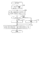
図示されるモータジェネレータ10は、インバータIVを介して高電圧バッテリ12やコンデンサ14に接続されている。ここで、インバータIVは、パワースイッチング素子Sup,Sunの直列接続体と、パワースイッチング素子Svp,Svnの直列接続体と、パワースイッチング素子Swp,Swnの直列接続体とを備えており、これら各直列接続体の接続点がモータジェネレータ10のU,V,W相にそれぞれ接続されている。これらパワースイッチング素子Sup,Sun,Svp,Svn,Swp,Swnとして、本実施形態では、絶縁ゲートバイポーラトランジスタ(IGBT)が用いられている。そして、これらにはそれぞれ、ダイオードDup,Dun,Dvp,Dvn,Dwp,Dwn,Dup,Dunが逆並列に接続されている。
The illustrated
制御装置20は、低電圧バッテリ18を電源とする制御装置である。制御装置20は、モータジェネレータ10を制御対象とし、その制御量を所望に制御すべく、インターフェース16を介してインバータIVを操作する。ここで、インターフェース16は、高電圧バッテリ12を備えて構成される高電圧システムと、低電圧バッテリ18を備えて構成される低電圧システムとを絶縁するための絶縁手段を備えるものである。
The
上記制御量の制御に際し、制御装置20では、モータジェネレータ10の状態量を検出する各種センサの検出値を参照する。ここで、各種センサとしては、U相を流れる電流を検出する電流センサ30a、30bや、V相を流れる電流を検出する電流センサ32a,32bや、電気角を検出する角度センサ40等がある。
In the control of the control amount, the
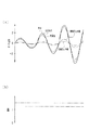
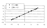
また、制御装置20では、電流センサ30a,30bや、電流センサ32a,32bの異常の有無を診断する異常診断処理を行なう。詳しくは、同相を流れる電流を検出する一対の電流センサ30a,30b(または電流センサ32a,32b)のそれぞれの検出値を座標とする座標系におけるこれら検出値iua,iub(iva,ivb)の描く軌跡と、基準となる軌跡との比較に基づき異常の有無を診断する。詳しくは、図2に示されるように、例えば電流センサ30a,30bのそれぞれについての同時期の検出値iua(n),iub(n)の組P(n)と、別の同時期の検出値iua(n−1),iub(n−1)の組P(n−1)とを結ぶ線分の傾きに基づき、異常の有無を診断する。図2では、横軸を電流センサ30aの検出値とするとともに縦軸を電流センサ30bの検出値とし、実線にて基準となる直線を示し、2点鎖線にて異常時の直線を示す。
Further, the
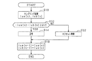
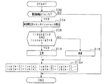
図3に、本実施形態にかかる異常診断処理の手順を示す。この処理は、制御装置20によって、例えば所定周期(電気角周期等)で繰り返し実行される。なお、以下では、U相の電流センサ30a,30bの異常の有無の診断処理を例示しており、V相の電流センサ32a,32bの異常の有無の診断処理については、同様であるためその記載を割愛した。
FIG. 3 shows a procedure of abnormality diagnosis processing according to the present embodiment. This process is repeatedly executed by the
この一連の処理では、まずステップS10において、電流センサ30a,30bのそれぞれの検出値iua(n),iub(n)を取得する。続くステップS12においては、今回のステップS10の処理において取得された検出値iua(n),iub(n)と、前回のステップS10の処理において取得された検出値iua(n−1),iub(n−1)とを結ぶ線分の傾きSL(n)に基づき、電流センサ30a,30bの異常の有無を診断する。ここで、一対の電流センサ30a,30bの双方が、基準となる特性を有するものである場合、これら一対の電流センサ30a,30bの検出値が等しくなるため、上記傾きSL(n)は、「1」となる。このため、傾きSL(n)と「1」とのずれ量が閾値δ以下である場合には、ステップS14において、正常と診断することができる。これに対し、ずれ量が閾値δよりも大きい場合には、ステップS16において異常と診断する。
In this series of processing, first, in step S10, respective detection values iua (n) and iub (n) of the
ステップS14,S16の処理が完了する場合、ステップS18において、検出値iua(n),iub(n)を検出値iua(n−1),iub(n−1)とする。なお、ステップS18の処理が完了する場合には、この一連の処理は一旦終了する。 When the processes of steps S14 and S16 are completed, the detected values iua (n) and iub (n) are set as the detected values iua (n-1) and iub (n-1) in step S18. In addition, when the process of step S18 is completed, this series of processes is once complete | finished.
このように、本実施形態では、傾きSL(n)を用いるため、診断実行頻度を十分大きくしつつも高精度の診断が可能となる。以下、これについて説明する。 As described above, in the present embodiment, since the slope SL (n) is used, it is possible to perform highly accurate diagnosis while sufficiently increasing the diagnosis execution frequency. This will be described below.
図4(a)は、一対の電流センサ30a,30bの検出値の推移を示す。ここでは、一対の電流センサ30a,30bの一方が基準となる特性を有して且つ、他方が基準となる特性に対してずれを有するもののそのずれ量が許容範囲内となる例を示す。本実施形態では、基準となる特性は、電流センサ30a,30bの特性として許容される範囲内の中央の特性を有するものを採用している。このため、図中、実線にて基準となる特性としての正常中央品を示し、一点鎖線にてこれとは許容範囲内でずれを有する正常公差内品を示している。なお、図中、振幅の小さい第3の正弦波は、正常中央品の検出値と正常公差内品の検出値との差を示す。図示されるように、差は周期的に変動している。図4(b)は、差のヒストグラムである。
FIG. 4A shows transition of detection values of the pair of
図4(b)に、一対の電流センサ30a,30bの一方が正常中央品(実線)であって且つ、他方が異常を生じているもの(一点鎖線)となる例を示す。なお、図中、振幅の小さい第3の正弦波は、正常中央品の検出値と異常品の検出値との差を示す。図示されるように、差は周期的に変動している。図2(d)は、差のヒストグラムである。
FIG. 4B shows an example in which one of the pair of
ここで、図4(b)および図4(d)からわかるように、正常中央品の検出値と正常公差内品の検出値と差と、正常中央品の検出値と異常品の検出値との差とは、その値が重複しうる。このため、差と閾値との大小比較に基づき異常の有無を診断するためには、差が大きくなる領域に限って異常診断を行なう必要が生じる。このため、異常の診断機会が低減される。さらに、差が大きくなる領域を特定する処理が必要となるため、制御装置20の演算負荷が増加する。
Here, as can be seen from FIG. 4 (b) and FIG. 4 (d), the detected value of the normal center product, the detected value of the normal tolerance product, the difference between the detected value of the normal center product and the detected value of the abnormal product The difference between the values may overlap. For this reason, in order to diagnose the presence or absence of an abnormality based on a comparison between the difference and the threshold value, it is necessary to perform an abnormality diagnosis only in a region where the difference is large. For this reason, an abnormality diagnosis opportunity is reduced. Furthermore, since the process which pinpoints the area | region where a difference becomes large is required, the calculation load of the
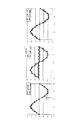
これに対し、傾きSL(n)は、図5(a)および図5(b)に示すように、タイミングによらず略一定である。図5(c)に、傾きのヒストグラムを示す。このように、傾きSL(n)を用いることで、任意の検出タイミングにおける検出値の組を用いて異常の有無を診断することができるため、異常診断機会を十分に確保することができる。 On the other hand, the slope SL (n) is substantially constant regardless of the timing, as shown in FIGS. 5 (a) and 5 (b). FIG. 5C shows a histogram of inclination. In this manner, by using the slope SL (n), it is possible to diagnose the presence or absence of abnormality using a set of detection values at an arbitrary detection timing, and therefore sufficient abnormality diagnosis opportunities can be ensured.
さらに、この傾きは、図6に示されるように、電流の振幅が変化する場合であっても、略一定に保たれる。ちなみに、図6(b)における一点鎖線は、正常中央品と正常公差内品とによって生成される傾きを示し、2点鎖線は、正常中央品と異常品とによって生成される傾きを示す。これに対し、一対の電流センサの検出値の差の最大値は、図6(a)に示すように、振幅が大きくなるほど大きくなり、振幅に依存する。このため、上記差と閾値との比較に基づく異常診断は、いっそう困難なものとなる。 Further, as shown in FIG. 6, this inclination is kept substantially constant even when the amplitude of the current changes. Incidentally, the alternate long and short dash line in FIG. 6B indicates the inclination generated by the normal center product and the normal tolerance product, and the two-dot chain line indicates the inclination generated by the normal center product and the abnormal product. In contrast, as shown in FIG. 6A, the maximum difference between the detection values of the pair of current sensors increases as the amplitude increases, and depends on the amplitude. For this reason, abnormality diagnosis based on the comparison between the difference and the threshold value becomes more difficult.
なお、上記閾値δは、正常公差内品と異常品とを識別可能な値に設定されるのみならず、電流センサ30a,30bの検出値iua(n),iub(n)の検出タイミング同士のずれ等を考慮して設定することが望ましい。ここで、ずれは、例えば、制御装置20が一対の電流センサ30a,30bによって検出される検出値を同時にサンプリングしようとする際に生じる同時性に関する誤差や、電流センサ30a,30bがその検出信号を制御装置20に伝達させる際に要する時間同士の差等に起因したものである。
The threshold value δ is not only set to a value that can distinguish between normal tolerance products and abnormal products, but also between the detection timings of the detection values iua (n) and iub (n) of the
以上詳述した本実施形態によれば、以下の効果が得られるようになる。 According to the embodiment described in detail above, the following effects can be obtained.
(1)1の相についての複数の電流センサ30a,30b(電流センサ32a,32b)のそれぞれの検出値iua,iub(iva,ivb)によって描かれる軌跡の傾きと、基準となる傾きとの比較に基づき、これら複数の電流センサ30a,30b(電流センサ32a,32b)の異常の有無を診断した。これにより、異常の有無を好適に診断することができる。
(1) Comparison between the inclination of the trajectory drawn by the detected values iua and iub (iva, ivb) of the plurality of
(2)軌跡の傾きを算出するに際し、上記検出値iua,iub等の複数組を用いた。これにより、1組のみを用いて診断を行なう場合と比較して、診断精度を向上させることができる。 (2) When calculating the inclination of the trajectory, a plurality of sets of the detection values iua, iub, etc. were used. Thereby, compared with the case where it diagnoses using only one set, diagnostic accuracy can be improved.
(3)上記検出値iua,iub等の組についての時系列データのうち、互いに隣接する一対の組を結ぶことで軌跡の傾きを算出した。これにより、異常診断のために記憶しておくデータ量を小さくすることができる。 (3) Of the time-series data for the set of detection values iua, iub, etc., the inclination of the trajectory was calculated by connecting a pair of sets adjacent to each other. Thereby, the data amount memorize | stored for abnormality diagnosis can be made small.
(第2の実施形態)
以下、第2の実施形態について、先の第1の実施形態との相違点を中心に図面を参照しつつ説明する。
(Second Embodiment)
Hereinafter, the second embodiment will be described with reference to the drawings with a focus on differences from the first embodiment.
図7に、本実施形態にかかる異常診断処理の手順を示す。この処理は、制御装置20によって、例えば所定周期で繰り返し実行される。なお、図7に示す処理において、先の図3に示した処理と同一の処理については、便宜上同一のステップ番号を付している。以下では、U相の電流センサ30a,30bの異常の有無の診断処理を例示しており、V相の電流センサ32a,32bの異常の有無の診断処理については、同様であるためその記載を割愛している。
FIG. 7 shows a procedure of abnormality diagnosis processing according to the present embodiment. This process is repeatedly executed by the
この一連の処理では、ステップS12において否定判断される場合、ステップS20において、異常カウンタCaをインクリメントとする。続くステップS22では、異常カウンタCaが閾値回数Cth(>1)以上であるか否かを判断する。この処理は、電流センサ30a,30bに異常があるか否かを診断する処理である。すなわち、本実施形態では、傾きSL(n)の「1」からのずれが閾値δを上回る場合であっても、「1」度だけでは、異常がある旨診断せず、閾値回数以上となることで異常がある旨診断する。これにより、電流センサ30a,30bの出力等にノイズ等が混入した場合であっても、これにより異常がある旨の誤診断がなされることを回避することができる。なお、本実施形態では、ステップS12において肯定判断される場合、ステップS14aにおいて正常である旨診断するとともに異常カウンタCaを初期化している。
In this series of processes, if a negative determination is made in step S12, the abnormality counter Ca is incremented in step S20. In a succeeding step S22, it is determined whether or not the abnormality counter Ca is equal to or greater than the threshold number Cth (> 1). This process is a process of diagnosing whether or not the
(第3の実施形態)
以下、第3の実施形態について、先の第1の実施形態との相違点を中心に図面を参照しつつ説明する。
(Third embodiment)
Hereinafter, the third embodiment will be described with reference to the drawings with a focus on differences from the first embodiment.
図8に、本実施形態にかかる異常診断処理の手順を示す。この処理は、制御装置20によって、例えば所定周期で繰り返し実行される。なお、図8に示す処理において、先の図3に示した処理と同一の処理については、便宜上同一のステップ番号を付している。以下では、U相の電流センサ30a,30bの異常の有無の診断処理を例示しており、V相の電流センサ32a,32bの異常の有無の診断処理については、同様であるためその記載を割愛している。
FIG. 8 shows a procedure of abnormality diagnosis processing according to the present embodiment. This process is repeatedly executed by the
この一連の処理では、ステップS10の処理の後、ステップS24において、傾きSL(n)のm(>1)個の平均値Iを算出する。続くステップS26では、平均値Iと「1」とのずれが閾値δ以下であるか否かを判断する。この処理は、電流センサ30a,30bに異常があるか否かを診断するための処理である。このように、本実施形態では、平均値を用いることで、電流センサ30a,30bの出力等にノイズ等が混入した場合であっても、これにより異常がある旨の誤診断がなされることを回避することができる。
In this series of processes, after the process of step S10, in step S24, m (> 1) average values I of the slope SL (n) are calculated. In a succeeding step S26, it is determined whether or not the difference between the average value I and “1” is equal to or less than the threshold value δ. This process is a process for diagnosing whether or not the
なお、ステップS14、S16の処理が完了する場合、ステップS18aにおいて、検出値iua(n),iub(n)を検出値iua(n−1),iub(n−1)とするのに先立ち、前回以前の検出値iua(n−1),iub(n−1)についても、順次、サンプリング番号を「1」ずつデクリメントする。 When the processes of steps S14 and S16 are completed, prior to setting the detection values iua (n) and iub (n) to the detection values iua (n−1) and iub (n−1) in step S18a, For the detection values iua (n−1) and iub (n−1) before the previous time, the sampling number is sequentially decremented by “1”.
(第4の実施形態)
以下、第4の実施形態について、先の第1の実施形態との相違点を中心に図面を参照しつつ説明する。
(Fourth embodiment)
Hereinafter, the fourth embodiment will be described with reference to the drawings with a focus on differences from the first embodiment.
図9に、本実施形態にかかる異常診断処理の手順を示す。この処理は、制御装置20によって、例えば所定周期で繰り返し実行される。なお、図9に示す処理において、先の図3に示した処理と同一の処理については、便宜上同一のステップ番号を付している。以下では、U相の電流センサ30a,30bの異常の有無の診断処理を例示しており、V相の電流センサ32a,32bの異常の有無の診断処理については、同様であるためその記載を割愛している。
FIG. 9 shows a procedure of abnormality diagnosis processing according to the present embodiment. This process is repeatedly executed by the
この一連の処理では、ステップS10の処理の後、ステップS28において、傾きSL(n)を算出する上での分母がゼロとなるか否かを判断する。すなわち、検出値iub(n)と検出値iub(n−1)との差がゼロであるか否かを判断する。この処理は、傾きSL(n)の算出が不可能か否かを判断するためのものある。そして、分母がゼロであると判断される場合には、傾きを算出することなくステップS18に移行する。 In this series of processes, after the process of step S10, in step S28, it is determined whether or not the denominator for calculating the slope SL (n) is zero. That is, it is determined whether or not the difference between the detection value iub (n) and the detection value iub (n−1) is zero. This process is for determining whether the slope SL (n) cannot be calculated. And when it is judged that a denominator is zero, it transfers to step S18, without calculating inclination.
(第5の実施形態)
以下、第5の実施形態について、先の第1の実施形態との相違点を中心に図面を参照しつつ説明する。
(Fifth embodiment)
Hereinafter, a fifth embodiment will be described with reference to the drawings, focusing on differences from the first embodiment.
図10に、本実施形態にかかる異常診断処理の手順を示す。この処理は、制御装置20によって、例えば所定周期で繰り返し実行される。なお、図10に示す処理において、先の図3に示した処理と同一の処理については、便宜上同一のステップ番号を付している。以下では、U相の電流センサ30a,30bの異常の有無の診断処理を例示しており、V相の電流センサ32a,32bの異常の有無の診断処理については、同様であるためその記載を割愛している。
FIG. 10 shows a procedure of abnormality diagnosis processing according to the present embodiment. This process is repeatedly executed by the
本実施形態では、ステップS12aにおいて、傾きを、今回のステップS10の処理において取得された検出値iua(n),iub(n)と、前前回のステップS10の処理において取得された検出値iua(n−2),iub(n−2)とを結ぶ線分の傾きSL(n)とする。これにより、正弦波形状を有するモータジェネレータ10を流れる電流の極大点や極小点近傍において、時系列的に隣接する検出値の組の値が互いに等しくなる場合であっても、傾きSL(n)を定義することが可能となる。
In the present embodiment, in step S12a, the inclination is determined based on the detection values iua (n) and iub (n) acquired in the current processing in step S10, and the detection value iua (in the previous processing in step S10). n-2) and the inclination SL (n) of the line segment connecting iub (n-2). As a result, even in the vicinity of the maximum point and the minimum point of the current flowing through the
なお、ステップS14、S16の処理が完了する場合、ステップS18bにおいて、検出値iua(n),iub(n)を検出値iua(n−1),iub(n−1)とするに先立ち、検出値iua(n−1),iub(n−1)を検出値iua(n−2),iub(n−2)とする。 When the processes of steps S14 and S16 are completed, the detection values iua (n) and iub (n) are detected in step S18b prior to the detection values iua (n-1) and iub (n-1). The values iua (n−1) and iub (n−1) are set as detected values iua (n−2) and iub (n−2).
以上説明した本実施形態によれば、先の第1の実施形態の上記(1)、(2)の効果に加えて、更に以下の効果が得られるようになる。 According to this embodiment described above, the following effects can be obtained in addition to the effects (1) and (2) of the first embodiment.
(4)検出値の組についての時系列データのうち、互いに隣接しない一対の組を結ぶことで定まる傾きSL(n)を用いて異常の有無を診断した。これにより、隣接する検出タイミングにおいて検出値が一致する場合であっても、傾きを定義することができる。 (4) The presence or absence of abnormality was diagnosed using the slope SL (n) determined by connecting a pair of pairs that are not adjacent to each other among the time-series data for the set of detected values. Thereby, even when the detection values match at adjacent detection timings, the inclination can be defined.
(第6の実施形態)
以下、第6の実施形態について、先の第1の実施形態との相違点を中心に図面を参照しつつ説明する。
(Sixth embodiment)
Hereinafter, the sixth embodiment will be described with reference to the drawings with a focus on differences from the first embodiment.
図11に、本実施形態にかかる異常診断処理の手順を示す。この処理は、制御装置20によって、例えば所定周期で繰り返し実行される。なお、図11に示す処理において、先の図3に示した処理と同一の処理については、便宜上同一のステップ番号を付している。以下では、U相の電流センサ30a,30bの異常の有無の診断処理を例示しており、V相の電流センサ32a,32bの異常の有無の診断処理については、同様であるためその記載を割愛している。
FIG. 11 shows a procedure of abnormality diagnosis processing according to the present embodiment. This process is repeatedly executed by the
本実施形態では、ステップS12bにおいて、傾きを、今回のステップS10の処理において取得された検出値iua(n),iub(n)と、前回のステップS10の処理において取得された検出値iua(n−1),iub(n−1)と、前前回のステップS10の処理において取得された検出値iua(n−2),iub(n−2)とによって定義される平均的な傾きSL(n)とする。この処理も、先の図5のステップS12aと同様、正弦波形状を有するモータジェネレータ10を流れる電流の極大点や極小点近傍において、時系列的に隣接する検出値の組の値が互いに等しくなりうることに鑑みたものである。
In the present embodiment, in step S12b, the inclination is determined based on the detection values iua (n) and iub (n) acquired in the current processing of step S10, and the detection value iua (n) acquired in the previous processing of step S10. −1), iub (n−1) and the average slope SL (n) defined by the detection values iua (n−2) and iub (n−2) acquired in the processing of the previous step S10. ). Also in this process, as in step S12a of FIG. 5, the values of the detection value pairs adjacent in time series are equal to each other in the vicinity of the maximum point and the minimum point of the current flowing through the
(第7の実施形態)
以下、第7の実施形態について、先の第1の実施形態との相違点を中心に図面を参照しつつ説明する。
(Seventh embodiment)
Hereinafter, the seventh embodiment will be described with reference to the drawings with a focus on differences from the first embodiment.
上記第1の実施形態では、先の図4等に示したように、検出される電流値の大きさ(振幅)が変化する異常(ゲイン異常)の有無を診断したが、本実施形態では、これに加えて更に、図12に示すオフセット異常の有無を診断する。ここで、オフセット異常とは、電流値が所定量だけ常時ずれている異常のことである。こうした異常が診断対象となる一対の電流センサ30a,30bのいずれかに生じる場合、先の第1の実施形態に示した手法では正常である旨誤診断がなされるおそれがある。そこで本実施形態では、一対の電流センサ30a,30bの双方が正常である場合にこれらの検出値の組の描く軌跡である傾き1の直線と、電流センサ30a,30bの実際の検出値の組との距離によってオフセット異常の有無を診断する。
In the first embodiment, as shown in FIG. 4 and the like, the presence or absence of an abnormality (gain abnormality) in which the magnitude (amplitude) of the detected current value changes is diagnosed, but in this embodiment, In addition to this, the presence or absence of an offset abnormality shown in FIG. 12 is diagnosed. Here, the offset abnormality is an abnormality in which the current value is always shifted by a predetermined amount. When such an abnormality occurs in any one of the pair of
図13に、本実施形態にかかる異常診断処理の手順を示す。この処理は、制御装置20によって、例えばゲイン異常診断において正常である旨判断される都度実行される。なお、図13に示す処理において、先の図3に示した処理と同一の処理については、便宜上同一のステップ番号を付している。以下では、U相の電流センサ30a,30bの異常の有無の診断処理を例示しており、V相の電流センサ32a,32bの異常の有無の診断処理については、同様であるためその記載を割愛している。
FIG. 13 shows a procedure of abnormality diagnosis processing according to the present embodiment. This process is executed by the
この一連の処理では、ステップS10の処理の後、ステップS30において、これら検出値の組と傾き1で原点を通る直線との距離が所定以下であるか否かを判断する。具体的には、検出値iua(n)と検出値iub(n)との差の絶対値が閾値h以下であるか否かを判断する。ここで、上記差の絶対値は、上記距離に比例する量である。そして、ステップS32において肯定判断される場合には、ステップS14において正常である旨判断する一方、否定判断される場合には、ステップS32においてオフセット異常である旨判断する。 In this series of processes, after the process of step S10, in step S30, it is determined whether or not the distance between the set of detected values and a straight line passing through the origin with an inclination of 1 is equal to or less than a predetermined value. Specifically, it is determined whether or not the absolute value of the difference between the detected value iua (n) and the detected value iub (n) is equal to or less than the threshold value h. Here, the absolute value of the difference is an amount proportional to the distance. If an affirmative determination is made in step S32, it is determined in step S14 that it is normal. If a negative determination is made, it is determined in step S32 that the offset is abnormal.
以上説明した本実施形態によれば、先の第1の実施形態の上記各効果に加えて、更に以下の効果が得られるようになる。 According to the present embodiment described above, the following effects can be obtained in addition to the above-described effects of the first embodiment.
(5)傾き1で原点を通る直線と検出値の組との距離に応じてオフセット異常の有無を診断した。これにより、先の図3の手法では検出できないオフセット異常を検出することができる。 (5) The presence / absence of an offset abnormality was diagnosed according to the distance between a straight line passing through the origin with an inclination of 1 and the set of detected values. Thereby, it is possible to detect an offset abnormality that cannot be detected by the method of FIG.
(第8の実施形態)
以下、第8の実施形態について、先の第1の実施形態との相違点を中心に図面を参照しつつ説明する。
(Eighth embodiment)
Hereinafter, the eighth embodiment will be described with reference to the drawings with a focus on differences from the first embodiment.
図14に、本実施形態にかかる異常診断処理の手順を示す。この処理は、制御装置20によって、例えば所定周期で繰り返し実行される。なお、図14に示す処理において、先の図3に示した処理と同一の処理については、便宜上同一のステップ番号を付している。以下では、U相の電流センサ30a,30bの異常の有無の診断処理を例示しており、V相の電流センサ32a,32bの異常の有無の診断処理については、同様であるためその記載を割愛している。
FIG. 14 shows a procedure of abnormality diagnosis processing according to the present embodiment. This process is repeatedly executed by the
この一連の処理では、ステップS10の処理が完了すると、ステップS34において、単回帰直線を算出する。すなわち、電流センサ30aの検出値を説明変数Aとして且つ電流センサ30bの検出値を目的変数Bとする単回帰直線「B=k・A+const」の係数kおよび定数constを、検出値の複数組から算出する。ここでは、周知の最小2乗法等を用いればよい。
In this series of processes, when the process of step S10 is completed, a single regression line is calculated in step S34. That is, a coefficient k and a constant const of a single regression line “B = k · A + const” having the detection value of the current sensor 30a as an explanatory variable A and the detection value of the
続くステップS36においては、係数kの絶対値と「1」との差が閾値δ以下であることと、定数constの絶対値が閾値Cth以下であることとの論理積が真であるか否かを判断する。この処理は、単回帰直線と傾き1の原点を通る直線との乖離度合いに基づき異常の有無を診断するものである。そして、論理積が真である場合には、ステップS14において正常と判断し、論理積が偽である場合にはステップS16において異常であると判断する。
In the subsequent step S36, whether or not the logical product of the difference between the absolute value of the coefficient k and “1” being equal to or smaller than the threshold δ and the absolute value of the constant const being equal to or smaller than the threshold Cth is true. Judging. This process diagnoses the presence or absence of an abnormality based on the degree of deviation between the single regression line and the straight line passing through the origin of
以上説明した本実施形態によれば、先の第1の実施形態の上記(1)、(2)の効果に加えて、更に以下の効果が得られるようになる。 According to this embodiment described above, the following effects can be obtained in addition to the effects (1) and (2) of the first embodiment.
(6)検出値の組によって算出される単回帰直線と基準となる直線との乖離度合いに基づき異常の有無を診断した。これにより、ノイズに対する耐性の高い診断を行なうことができる。 (6) The presence / absence of abnormality was diagnosed based on the degree of deviation between the single regression line calculated from the set of detected values and the reference straight line. Thereby, diagnosis with high tolerance to noise can be performed.
(第9の実施形態)
以下、第9の実施形態について、先の第8の実施形態との相違点を中心に図面を参照しつつ説明する。
(Ninth embodiment)
Hereinafter, the ninth embodiment will be described with reference to the drawings with a focus on differences from the eighth embodiment.
図15に、電流の振幅が小さい場合について、正常中央品と、正常中央品から特性ずれが生じたものとの検出値の推移を示す。図示されるように、電流が小さい場合、ノイズの影響と電流センサの特性ずれの影響とを識別することが困難となる。実際、図16に、正常中央品の検出値の組によって算出される単回帰直線と、異常品の検出値の組によって算出された単回帰直線とを示すように、これらは略一致する。そこで、本実施形態では、電流の振幅が小さい場合に、異常診断を禁止する。 FIG. 15 shows the transition of the detected values of the normal center product and the one in which the characteristic deviation occurs from the normal center product when the current amplitude is small. As shown in the figure, when the current is small, it becomes difficult to distinguish between the influence of noise and the influence of characteristic deviation of the current sensor. In fact, FIG. 16 shows that the single regression line calculated by the set of detected values of the normal center product and the single regression line calculated by the set of detected values of the abnormal product are substantially coincident. Therefore, in the present embodiment, abnormality diagnosis is prohibited when the current amplitude is small.
図17に、本実施形態にかかる異常診断処理の手順を示す。この処理は、制御装置20によって、例えば所定周期で繰り返し実行される。なお、図17に示す処理において、先の図14に示した処理と同一の処理については、便宜上同一のステップ番号を付している。以下では、U相の電流センサ30a,30bの異常の有無の診断処理を例示しており、V相の電流センサ32a,32bの異常の有無の診断処理については、同様であるためその記載を割愛している。
FIG. 17 shows a procedure of abnormality diagnosis processing according to the present embodiment. This process is repeatedly executed by the
この一連の処理では、まずステップS38において、電流振幅が閾値Iath以上であるか否かを判断する。そして、閾値Iath未満であると判断される場合、この一連の処理を一旦終了する。 In this series of processes, first, in step S38, it is determined whether or not the current amplitude is greater than or equal to a threshold value Iath. And when it is judged that it is less than the threshold value Iath, this series of processes is once terminated.
以上説明した本実施形態によれば、先の第8の実施形態の上記各効果に加えて、更に以下の効果が得られるようになる。 According to the present embodiment described above, the following effects can be obtained in addition to the effects of the previous eighth embodiment.
(7)モータジェネレータ10を流れる電流の振幅が所定以下である場合、異常の有無の診断処理を禁止した。これにより、精度の低い診断がなされることを回避することができる。
(7) When the amplitude of the current flowing through the
(第10の実施形態)
以下、第10の実施形態について、先の第8の実施形態との相違点を中心に図面を参照しつつ説明する。
(Tenth embodiment)
Hereinafter, the tenth embodiment will be described with reference to the drawings with a focus on differences from the previous eighth embodiment.
図18に、本実施形態にかかる異常診断処理の手順を示す。この処理は、制御装置20によって、例えば所定周期で繰り返し実行される。なお、図18に示す処理において、先の図14に示した処理と同一の処理については、便宜上同一のステップ番号を付している。以下では、U相の電流センサ30a,30bの異常の有無の診断処理を例示しており、V相の電流センサ32a,32bの異常の有無の診断処理については、同様であるためその記載を割愛している。
FIG. 18 shows a procedure of abnormality diagnosis processing according to the present embodiment. This process is repeatedly executed by the
この一連の処理では、ステップS34aにおいて、検出値の複数組を用いて、特定の点(a,b)を通る単回帰直線を算出する。ここで、特定の点(a,b)は、「a=b」であって且つ、モータジェネレータ10の運転領域において流れうる最大電流値よりも十分大きい値に設定される。これは、検出値の組のうち原点から離間した組にノイズが集中的に重畳した場合における診断精度の低下を抑制するための設定である。すなわち、最小2乗法を用いて単回帰直線を算出する場合、原点から離間した検出値の組の影響が顕著となりやすいため、これにノイズが重畳した場合にノイズの影響が大きくなり、ひいては診断精度の低下を招く懸念がある。これに対し、上記設定をすることで、その影響を好適に低減することができる。
In this series of processing, in step S34a, a single regression line passing through a specific point (a, b) is calculated using a plurality of sets of detected values. Here, the specific point (a, b) is set to “a = b” and a value sufficiently larger than the maximum current value that can flow in the operation region of the
以上説明した本実施形態によれば、先の第8の実施形態の上記各効果に加えて、更に以下の効果が得られるようになる。 According to the present embodiment described above, the following effects can be obtained in addition to the effects of the previous eighth embodiment.
(8)単回帰直線を、電流値としてとり得ないと想定される大電流に対応する点を通る直線とした。これにより、ノイズ等の影響を好適に抑制することができる。 (8) The single regression line is a straight line passing through a point corresponding to a large current that cannot be assumed as a current value. Thereby, the influence of noise etc. can be suppressed suitably.
(第11の実施形態)
以下、第11の実施形態について、先の第1の実施形態との相違点を中心に図面を参照しつつ説明する。
(Eleventh embodiment)
Hereinafter, the eleventh embodiment will be described with reference to the drawings, centering on differences from the first embodiment.
本実施形態では、先の第1の実施形態において対象とした異常のみならず、電流センサの異常のうち図19に例示する位相ずれ異常の有無をも診断する。図19(a)に示すように、この異常は、振幅が中央正常品におけるものと同一であるものの、位相がずれる異常である。この場合、図19(b)に示すように、検出値iuaと検出値iubとの描く軌跡は楕円となる。このため、楕円を描くか否かによって位相ずれの有無を診断することができる。 In the present embodiment, not only the abnormality targeted in the first embodiment, but also the presence or absence of the phase shift abnormality illustrated in FIG. 19 among the abnormality of the current sensor is diagnosed. As shown in FIG. 19A, this abnormality is an abnormality in which the amplitude is the same as that in the central normal product but the phase is shifted. In this case, as shown in FIG. 19B, the locus drawn by the detection value iua and the detection value iub is an ellipse. For this reason, the presence or absence of a phase shift can be diagnosed by whether or not an ellipse is drawn.
図20に、本実施形態にかかる異常診断処理の手順を示す。この処理は、制御装置20によって、例えば所定周期で繰り返し実行される。なお、図20に示す処理において、先の図3に示した処理と同一の処理については、便宜上同一のステップ番号を付している。以下では、U相の電流センサ30a,30bの異常の有無の診断処理を例示しており、V相の電流センサ32a,32bの異常の有無の診断処理については、同様であるためその記載を割愛している。
FIG. 20 shows a procedure of abnormality diagnosis processing according to the present embodiment. This process is repeatedly executed by the
この一連の処理では、ステップS10の処理の後、ステップS40において、今回の検出値iua(n),iub(n)と、前回の検出値iua(n−1)、iub(n−1)とを結ぶ線分の傾きSL(n)を算出し、続くステップS42では、傾きSL(n)を有する単位ベクトルe(n)を算出する。次に、ステップS44では、今回のステップS42において算出された単位ベクトルe(n)と、前回のステップS42において算出された単位ベクトルe(n−1)との内積を算出する。これは、今回の傾きと前回の傾きとのなす角度と相関を有するパラメータを算出する処理である。すなわち、これらの内積は、上記傾きθを独立変数とする余弦関数cosθとなる。そして、ステップS46では、余弦関数cosθから把握される位相遅れが許容範囲内であるか否かを判断する。ここでは、余弦関数cosθの時系列データから把握される傾きの推移が位相遅れ時に生じる楕円によるものである場合に許容範囲にないと判断すればよい。そして、許容範囲にあると判断される場合には、ステップS14において正常である旨判断する一方、許容範囲に無いと判断される場合には、ステップS48において異常である旨判断する。 In this series of processing, after the processing in step S10, in step S40, the current detection values iua (n) and iub (n) and the previous detection values iua (n-1) and iub (n-1) In step S42, a unit vector e (n) having a slope SL (n) is calculated. Next, in step S44, an inner product of the unit vector e (n) calculated in the current step S42 and the unit vector e (n-1) calculated in the previous step S42 is calculated. This is a process of calculating a parameter having a correlation with an angle formed by the current inclination and the previous inclination. That is, these inner products become a cosine function cos θ having the gradient θ as an independent variable. In step S46, it is determined whether or not the phase delay obtained from the cosine function cos θ is within an allowable range. Here, it is only necessary to determine that the change of the slope grasped from the time series data of the cosine function cos θ is not within the allowable range when it is due to an ellipse generated at the time of phase delay. If it is determined that it is within the allowable range, it is determined in step S14 that it is normal. If it is determined that it is not within the allowable range, it is determined that it is abnormal in step S48.
なお、ステップS14、S48の処理が完了する場合、ステップS50において、ステップS46aの処理に用いた検出値iua(n),iub(n)、iua(n−1),iub(n−1)、…や、傾きSL,単位ベクトル、余弦関数を「1」ずつデクリメントする。 When the processes in steps S14 and S48 are completed, in step S50, the detection values iua (n), iub (n), iua (n-1), iub (n-1), used for the process in step S46a are performed. ... or decrement the slope SL, the unit vector, and the cosine function by "1".
以上説明した本実施形態によれば、先の第1の実施形態の上記(1)の効果に加えて、更に以下の効果が得られるようになる。 According to the present embodiment described above, the following effects can be obtained in addition to the effect (1) of the first embodiment.
(9)傾きSLについての時系列に前後するもの同士のなす角度に基づき異常の有無を診断した。これにより、位相遅れにかかる異常の有無を診断することができる。 (9) The presence / absence of an abnormality was diagnosed based on the angle formed by the anteroposterior slope SL. Thereby, it is possible to diagnose the presence or absence of an abnormality related to the phase delay.
(第12の実施形態)
以下、第12の実施形態について、先の第11の実施形態との相違点を中心に図面を参照しつつ説明する。
(Twelfth embodiment)
Hereinafter, the twelfth embodiment will be described with reference to the drawings with a focus on differences from the eleventh embodiment.
図21に、本実施形態にかかる異常診断処理の手順を示す。この処理は、制御装置20によって、例えば所定周期で繰り返し実行される。なお、図21に示す処理において、先の図20に示した処理と同一の処理については、便宜上同一のステップ番号を付している。以下では、U相の電流センサ30a,30bの異常の有無の診断処理を例示しており、V相の電流センサ32a,32bの異常の有無の診断処理については、同様であるためその記載を割愛している。
FIG. 21 shows a procedure of abnormality diagnosis processing according to the present embodiment. This process is repeatedly executed by the
この一連の処理では、ステップS46aにおいて、単位ベクトルeの所定期間内における時系列データが許容範囲であるか否かを判断する。詳しくは、例えば電気角のN(=1,2,3…)周期における傾きの中央値や平均値、または最も頻度の高い値が許容範囲内であるか否かを判断する。これは、楕円の接線の傾きについて、中央値や平均値や最も頻度の高い値が定まることに鑑みたものである。すなわち、楕円に特有の中央値や平均値や最も頻度の高い値に近似する場合に許容範囲ではないと判断すればよい。また、例えば、電気角のN(=1,2,3…)周期における傾きの分布や分散等が許容範囲内であるか否かを判断してもよい。これは楕円の接線の傾きについて、分布や分散等が定まることに鑑みたものである。すなわち、楕円に特有の分布や分散等に近似する場合に許容範囲ではないと判断すればよい。 In this series of processing, in step S46a, it is determined whether or not the time-series data within the predetermined period of the unit vector e is within an allowable range. Specifically, for example, it is determined whether or not the median value or average value of the gradient in the N (= 1, 2, 3...) Period of the electrical angle or the most frequent value is within the allowable range. This is based on the fact that the median value, average value, and most frequent value are determined for the slope of the tangent line of the ellipse. That is, it is only necessary to determine that the value is not within the allowable range when approximating the median value, average value, or most frequent value peculiar to the ellipse. Further, for example, it may be determined whether or not the distribution or dispersion of the inclination in the N (= 1, 2, 3...) Period of the electrical angle is within an allowable range. This is in view of the fact that the distribution, dispersion, and the like of the slope of the tangent of the ellipse are determined. That is, it is only necessary to determine that it is not within the allowable range when approximating the distribution or variance peculiar to the ellipse.
以上説明した本実施形態によれば、先の第1の実施形態の上記(1)の効果に加えて、更に以下の効果が得られるようになる。 According to the present embodiment described above, the following effects can be obtained in addition to the effect (1) of the first embodiment.
(10)傾きSLについての所定期間における各値に基づき異常の有無を診断した。これにより、位相ずれ異常の有無を診断することができる。 (10) The presence / absence of an abnormality was diagnosed based on each value of the slope SL in a predetermined period. Thereby, the presence or absence of phase shift abnormality can be diagnosed.
(第13の実施形態)
以下、第13の実施形態について、先の第11の実施形態との相違点を中心に図面を参照しつつ説明する。
(13th Embodiment)
Hereinafter, a thirteenth embodiment will be described with reference to the drawings, centering on differences from the eleventh embodiment.
図22に、本実施形態にかかるシステム構成を示す。なお、図22において、先の図1に示した部材に対応する部材については便宜上同一の符号を付している。 FIG. 22 shows a system configuration according to the present embodiment. In FIG. 22, members corresponding to those shown in FIG. 1 are given the same reference numerals for convenience.
本実施形態では、モータジェネレータ10の各相を流れる電流を検出する電流センサを相毎に1つずつ備える。すなわち、U相の電流を検出する電流センサ30と、V相の電流を検出する電流センサ32と、W相の電流を検出する電流センサ34とを備える。ここで、例えば電流センサ30の検出値と電流センサ32の検出値とを座標軸とする座標系におけるこれら検出値の組の軌跡は、これら検出値が正常であれば楕円となる。これは、U相の電流とV相の電流とが振幅および周期が等しく固定された位相差を有するものであるためである。このため、正常時の楕円の軌跡からのずれに基づき異常の有無を診断することができる。
In the present embodiment, one current sensor for detecting a current flowing through each phase of the
図23に、本実施形態にかかる異常診断処理の手順を示す。この処理は、制御装置20によって、例えば所定周期で繰り返し実行される。以下では、U相の電流センサ30とV相の電流センサ32の異常の有無の診断処理を例示しており、W相の電流センサ34の異常の有無の診断処理については、電流センサ30または電流センサ32を電流センサ34に置き換えることで実現できるためその記載を割愛した。
FIG. 23 shows a procedure of abnormality diagnosis processing according to the present embodiment. This process is repeatedly executed by the
この一連の処理では、まずステップS60において、電流センサ30によるU相電流の検出値iu(n)と、電流センサ32によるV相電流の検出値iv(n)とを取得する。続くステップS62では、モータジェネレータ10のトルクTおよび電気角速度ωを取得する。続くステップS64では、トルクTおよび電気角速度ωによって定まる焦点(U1,V1)、(U2,V2)のそれぞれと、検出値iu(n)、iv(n)との距離の和Lを算出する。この処理は、電流センサ30,32が正常であるか否かを判断するためのものである。すなわち、これらが正常であればこれらの検出値の組は楕円を描く。そしてこの楕円は、一対の焦点からの距離の和Lが一定である。ただし、一対の焦点(U1,V1)、(U2,V2)は、電流の振幅に応じて変化する。このため、本実施形態では、電流の振幅と相関を有するパラメータとしてのトルクTおよび電気角速度ωに応じて一対の焦点(U1,V1)、(U2,V2)を可変設定する。すなわち、トルクTおよび電気角速度ωから想定される電流振幅に応じて一対の焦点(U1,V1)、(U2,V2)を可変設定する。
In this series of processing, first, in step S60, the detected value iu (n) of the U-phase current by the
続くステップS66では、上記距離の和Lと基準となる和Lrefとの差の絶対値が閾値ΔLth以下であるか否かを判断する。ここで、基準となる和Lrefは、電流の振幅と相関を有するパラメータとしてのトルクTおよび電気角速度ωに応じて可変設定される。すなわち、トルクTおよび電気角速度ωから想定される電流振幅に応じて基準となる和Lrefを可変設定する。 In the subsequent step S66, it is determined whether or not the absolute value of the difference between the distance sum L and the reference sum Lref is equal to or less than a threshold value ΔLth. Here, the reference sum Lref is variably set according to the torque T and the electrical angular velocity ω as parameters having a correlation with the amplitude of the current. That is, the reference sum Lref is variably set according to the current amplitude assumed from the torque T and the electrical angular velocity ω.
上記ステップS66において肯定判断される場合、ステップS68において正常であると判断する一方、否定判断される場合、ステップS70において異常であると判断する。そして、ステップS68,S70の処理が完了する場合、ステップS72において、検出値iu(n)を検出値iu(n−1)として且つ、検出値iv(n)を検出値iv(n−1)とする。 If an affirmative determination is made in step S66, it is determined normal in step S68, whereas if a negative determination is made, it is determined in step S70 that it is abnormal. When the processes of steps S68 and S70 are completed, in step S72, the detection value iu (n) is set as the detection value iu (n-1), and the detection value iv (n) is set as the detection value iv (n-1). And
以上説明した本実施形態によれば、先の第1の実施形態の上記(1)の効果に加えて、更に以下の効果が得られるようになる。 According to the present embodiment described above, the following effects can be obtained in addition to the effect (1) of the first embodiment.
(11)検出対象となる相の相違する電流の位相差から想定される楕円と、電流の検出値の組の軌跡との乖離度合いに基づき異常の有無を診断した。これにより、検出対象とする相が相違する複数の電流センサのそれぞれの検出値を用いてこれらの異常の有無を診断することができる。 (11) The presence / absence of an abnormality was diagnosed based on the degree of deviation between the ellipse assumed from the phase difference of the currents with different phases to be detected and the locus of the set of detected current values. Thereby, the presence or absence of these abnormalities can be diagnosed using the detection values of a plurality of current sensors having different phases to be detected.
(12)検出値の組と、一対の焦点(U1,V1)、(U2,V2)のそれぞれの距離の和Lに基づき、異常の有無を診断した。これにより、検出値の組の描く軌跡と正常時の楕円とのずれ度合いを把握することができる。 (12) The presence or absence of abnormality was diagnosed based on the set L of detection values and the sum L of the distances between the pair of focal points (U1, V1) and (U2, V2). Thereby, it is possible to grasp the degree of deviation between the locus drawn by the set of detection values and the normal ellipse.
(13)正常時において想定される楕円を、モータジェネレータ10の状態量に応じて可変設定した。これにより異常の有無の診断を高精度に行なうことができる。
(13) The ellipse assumed in the normal state is variably set according to the state quantity of the
(第14の実施形態)
以下、第14の実施形態について、先の第13の実施形態との相違点を中心に図面を参照しつつ説明する。
(Fourteenth embodiment)
Hereinafter, the fourteenth embodiment will be described with reference to the drawings with a focus on differences from the thirteenth embodiment.
図24に、本実施形態にかかる異常診断処理の手順を示す。この処理は、制御装置20によって、例えば所定周期で繰り返し実行される。なお、図24に示す処理において、先の図23に示した処理と同一の処理については、便宜上同一のステップ番号を付している。以下では、U相の電流センサ30とV相の電流センサ32の異常の有無の診断処理を例示しており、W相の電流センサ34の異常の有無の診断処理については、電流センサ30または電流センサ32を電流センサ34に置き換えることで実現できるためその記載を割愛した。
FIG. 24 shows a procedure of abnormality diagnosis processing according to the present embodiment. This process is repeatedly executed by the
本実施形態では、ステップS60の処理の後、ステップS74において、検出値の複数の組を用いて、多変調解析によって楕円を特定する。続くステップS76では、多変調解析によって特定された楕円と正常時に想定される楕円との差が許容範囲内にあるか否かを判断する。 In this embodiment, after the process of step S60, in step S74, an ellipse is specified by multi-modulation analysis using a plurality of sets of detected values. In a succeeding step S76, it is determined whether or not the difference between the ellipse specified by the multi-modulation analysis and the ellipse assumed at the normal time is within an allowable range.
(その他の実施形態)
なお、上記各実施形態は、以下のように変更して実施してもよい。
<傾きの算出手法について>
異なる2つの検出タイミングにおける検出値の組に基づく傾きの算出手法としては、上記第1〜5の実施形態において例示されるものに限らない。例えば時系列的に2サンプリング以上はなれた検出値の組を用いてもよい。
(Other embodiments)
Each of the above embodiments may be modified as follows.
<Slope calculation method>
The method for calculating the inclination based on the set of detection values at two different detection timings is not limited to that exemplified in the first to fifth embodiments. For example, a set of detected values that are more than two samplings in time series may be used.
3つ以上の検出タイミングにおける検出値の組から算出される平均的な傾きとしては、上記第3の実施形態や上記第6の実施形態において例示したものに限らない。例えば上記第3の実施形態の手法において、4つ以上の検出タイミングにおける検出値の組を用いて平均的な傾きを算出してもよい。
<単回帰直線を求めるものについて>
例えば、上記第8〜第10の実施形態において、単回帰直線の傾きのみを異常の有無の診断に用いたり、切片のみを異常の有無の診断に用いたりしてもよい。
<オフセット異常について>
上記第7の実施形態においては、オフセット異常の有無の診断のために用いるパラメータとして、基準となる直線「iua=iub」との距離を算出したが、これに限らず、上記直線の一部と検出値とによって生成される三角形の面積等、その相当量を算出するものであってもよい。
The average slope calculated from the set of detection values at three or more detection timings is not limited to those exemplified in the third embodiment and the sixth embodiment. For example, in the method of the third embodiment, an average inclination may be calculated using a set of detection values at four or more detection timings.
<About a simple regression line>
For example, in the eighth to tenth embodiments, only the slope of the single regression line may be used for diagnosing the presence or absence of abnormality, or only the intercept may be used for diagnosing the presence or absence of abnormality.
<About offset abnormality>
In the seventh embodiment, the distance to the reference straight line “iua = iub” is calculated as a parameter used for diagnosing the presence or absence of an offset abnormality. An equivalent amount such as an area of a triangle generated by the detected value may be calculated.
ちなみに、こうした異常診断とともに実行される他種の異常診断処理としては、上記第1の実施形態におけるものにも限らない。
<異なる2相の電流センサの異常診断について>
楕円の2つの焦点(U1,V1),(U2,V2)の座標を可変設定するためのモータジェネレータ10の状態量としては、トルクTおよび電気角速度ωに限らない。例えば、インバータIVの入力電圧、入力電流、入力電力等であってもよい。
Incidentally, other types of abnormality diagnosis processing executed together with such abnormality diagnosis are not limited to those in the first embodiment.
<Abnormality diagnosis of different two-phase current sensors>
The state quantities of the
モータジェネレータ10の状態量に応じた楕円の大きさの変化を補償する手法としては、焦点(U1,V1),(U2,V2)等を可変設定するものに限らない。例えば、モータジェネレータ10の状態量に応じて電流の検出値iua,iubを補正するものであってもよい。
<同一の検出対象の物理量を検出する複数のセンサについて>
同一の検出対象の物理量を検出する複数のセンサ(同一の物理量に対して同一の検出値を出力すると想定される複数のセンサ)としては、回転機の1つの相を流れる電流を検出する複数の電流センサに限らない。例えばインバータIVの入力電圧を検出する複数の電圧センサや、内燃機関の吸気通路に設けられる電子制御式スロットルバルブの開度を検出する複数のセンサ等であってもよい。
<その他>
・上記第7の実施形態では、ゲイン異常が生じていないと判断される場合に、図13の処理によってオフセット異常の有無を診断したが、これに限らない。例えば、傾きを用いた異常診断と図13に示した処理とを常時行なうようにしてもよい。なお、この場合、図13に示した処理によって直接的にオフセット異常が特定されるわけではない。
The method for compensating for the change in the size of the ellipse according to the state quantity of the
<About multiple sensors that detect physical quantities of the same detection target>
As a plurality of sensors that detect physical quantities of the same detection target (a plurality of sensors that are assumed to output the same detection value for the same physical quantity), a plurality of sensors that detect a current flowing through one phase of a rotating machine It is not limited to current sensors. For example, a plurality of voltage sensors that detect the input voltage of the inverter IV, a plurality of sensors that detect the opening degree of an electronically controlled throttle valve provided in the intake passage of the internal combustion engine, and the like may be used.
<Others>
In the seventh embodiment, when it is determined that no gain abnormality has occurred, the presence / absence of the offset abnormality is diagnosed by the processing of FIG. 13, but the present invention is not limited to this. For example, the abnormality diagnosis using the inclination and the processing shown in FIG. 13 may be always performed. In this case, the offset abnormality is not directly specified by the processing shown in FIG.
・上記第9の実施形態における異常診断の禁止処理の適用対象は、単回帰分析を用いる異常診断処理に限らない。同相の電流センサの検出値の組の軌跡として直線を想定するもの等にあっては、上記禁止処理の適用が有効である。 The application target of the abnormality diagnosis prohibition process in the ninth embodiment is not limited to the abnormality diagnosis process using single regression analysis. In the case of assuming a straight line as a locus of a set of detection values of in-phase current sensors, the application of the prohibition process is effective.
・異常診断に用いる電流センサとしては、2つに限らない。例えば同一相の電流を検出する3つの電流センサの検出値の組が3次元座標系において描く軌跡と基準となる直線とに基づき、異常の有無を診断してもよい。 -Current sensors used for abnormality diagnosis are not limited to two. For example, the presence or absence of an abnormality may be diagnosed based on a locus drawn by a set of detection values of three current sensors that detect currents of the same phase in a three-dimensional coordinate system and a reference straight line.
・傾きの算出に用いる検出値の組としては、複数組に限らない。例えば図25に例示するように、1組であってもよい。ここでは、ステップS12cにおいて、予め定められた点(ia,ib)と検出値の1組とによって結ばれる線分の傾きが算出されている。ちなみに、図25に示す処理は、所定周期で繰り返し実行されるものであり、先の図3に示した処理と同一の処理については、便宜上同一のステップ番号を付している。 -The set of detection values used for calculating the slope is not limited to a plurality of sets. For example, as illustrated in FIG. Here, in step S12c, the slope of a line segment connected by a predetermined point (ia, ib) and one set of detection values is calculated. Incidentally, the process shown in FIG. 25 is repeatedly executed at a predetermined cycle, and the same process as the process shown in FIG. 3 is given the same step number for the sake of convenience.
さらに、検出値の1組を通る傾き「1」の直線の切片と正常時の切片である「0」との乖離度合いに基づき異常の有無を診断してもよい。 Further, the presence / absence of an abnormality may be diagnosed based on the degree of deviation between a straight intercept of slope “1” passing through one set of detection values and “0” being a normal intercept.
10…モータジェネレータ、30,30a,30b、32,32a,32b、34…電流センサ、20…制御装置。
DESCRIPTION OF
Claims (31)
前記電流センサは、各別の複数のセンサを備え、
前記複数の電流センサのうちの少なくとも2つによって同一のタイミングで検出される電流の検出値を取得する取得手段と、
前記少なくとも2つの電流センサのそれぞれの検出値を座標軸とする座標系において前記取得手段によって取得された検出値によって描かれる軌跡と、基準となる軌跡との比較に基づき前記少なくとも2つの電流センサの異常の有無を診断する診断手段とを備えることを特徴とする電流センサの異常診断装置。 In an abnormality diagnosis device for a current sensor that detects a current flowing through a rotating machine,
The current sensor includes a plurality of different sensors,
Obtaining means for obtaining a detected value of a current detected at the same timing by at least two of the plurality of current sensors;
Abnormality of the at least two current sensors based on a comparison between a trajectory drawn by the detection value acquired by the acquisition means and a reference trajectory in a coordinate system having respective detection values of the at least two current sensors as coordinate axes An abnormality diagnosis device for a current sensor, comprising: diagnostic means for diagnosing the presence or absence of the current sensor.
前記電流センサは、前記多相回転機の少なくとも1の相を流れる電流を検出する複数のセンサを備え、
前記取得手段は、前記1の相についての前記複数のセンサの少なくとも2つによって同一のタイミングで検出される電流の検出値を取得するものであり、
前記診断手段は、前記1の相についての前記取得手段によって取得される前記少なくとも2つのセンサのそれぞれの検出値の複数組によって描かれる軌跡に基づき前記少なくとも2つのセンサの異常の有無を診断することを特徴とする請求項2記載の電流センサの異常診断装置。 The rotating machine is a multi-phase rotating machine;
The current sensor includes a plurality of sensors that detect a current flowing through at least one phase of the multiphase rotating machine,
The acquisition unit acquires a detection value of a current detected at the same timing by at least two of the plurality of sensors for the one phase,
The diagnosis means diagnoses the presence or absence of an abnormality in the at least two sensors based on a locus drawn by a plurality of sets of detection values of the at least two sensors acquired by the acquisition means for the one phase. The abnormality diagnosis apparatus for a current sensor according to claim 2.
前記診断手段は、前記直線と前記少なくとも2つのセンサによる検出値の組との距離に応じて前記複数のセンサの異常の有無を診断することを特徴とする請求項3〜12のいずれか1項に記載の電流センサの異常診断装置。 The reference trajectory is a straight line assumed when the at least two sensors for the one phase are normal,
13. The diagnosis unit according to claim 3, wherein the diagnosis unit diagnoses the presence or absence of abnormality of the plurality of sensors according to a distance between the straight line and a set of detection values of the at least two sensors. An abnormality diagnosis device for a current sensor as described in 1.
前記電流センサは、多相回転機の少なくとも1の相を流れる電流を検出する複数のセンサを備え、
前記取得手段は、前記1の相についての前記複数のセンサによって同一のタイミングで検出される電流の検出値を取得するものであり、
前記診断手段は、前記複数のセンサのそれぞれの検出値の組と、予め定められた傾きとによって定まる直線と前記座標軸との交点に基づき、前記複数のセンサの異常の有無を診断することを特徴とする請求項1〜3のいずれか1項に記載の電流センサの異常診断装置。 The rotating machine is a multi-phase rotating machine;
The current sensor includes a plurality of sensors that detect a current flowing through at least one phase of the multiphase rotating machine,
The acquisition means acquires a detection value of a current detected at the same timing by the plurality of sensors for the one phase,
The diagnosing means diagnoses the presence or absence of abnormality of the plurality of sensors based on the intersection of the straight line determined by a set of detection values of each of the plurality of sensors and a predetermined inclination and the coordinate axis. The abnormality diagnosis device for a current sensor according to any one of claims 1 to 3.
前記診断手段は、前記複数の電流センサのうちの2つのそれぞれの検出値の複数組によって定まる傾きについての所定期間における各値に基づき前記2つのセンサの異常の有無を診断することを特徴とする請求項2〜15のいずれか1項に記載の電流センサの異常診断装置。 The reference trajectory is an ellipse drawn by a set of these detection values when there is a phase lag between two of the plurality of current sensors.
The diagnosing means diagnoses the presence or absence of abnormality of the two sensors based on respective values in a predetermined period with respect to an inclination determined by a plurality of sets of two respective detection values of the plurality of current sensors. The abnormality diagnosis apparatus for a current sensor according to any one of claims 2 to 15.
前記複数の電流センサは、前記多相回転機の互いに相違する相を流れる電流を検出するセンサを含み、
前記軌跡は、前記互いに相違する相を流れる電流を検出する2つのセンサ同士に位相遅れがある場合にこれらの検出値の組によって描かれる楕円であることを特徴とする請求項2記載の電流センサの異常診断装置。 The rotating machine is a multi-phase rotating machine;
The plurality of current sensors include sensors that detect currents flowing through different phases of the multiphase rotating machine,
3. The current sensor according to claim 2, wherein the locus is an ellipse drawn by a set of detected values when there is a phase lag between the two sensors that detect currents flowing through different phases. Abnormality diagnosis device.
前記複数のセンサのうちの少なくとも2つによって同一のタイミングで検出される前記物理量の検出値を取得する取得手段と、
前記少なくとも2つのセンサのそれぞれの検出値を座標軸とする座標系において前記取得手段によって取得された検出値の複数組によって描かれる軌跡と、基準となる軌跡との比較に基づき前記少なくとも2つのセンサの異常の有無を診断する診断手段とを備えることを特徴とするセンサの異常診断装置。 About abnormality diagnosis devices for multiple sensors that detect physical quantities of the same detection target,
Obtaining means for obtaining a detection value of the physical quantity detected at the same timing by at least two of the plurality of sensors;
Based on a comparison between a trajectory drawn by a plurality of sets of detection values acquired by the acquisition means and a reference trajectory in a coordinate system having respective detection values of the at least two sensors as coordinate axes, An abnormality diagnosis apparatus for a sensor, comprising: a diagnosis unit that diagnoses whether there is an abnormality.
前記診断手段は、前記直線と前記少なくとも2つのセンサによる検出値の組との距離に応じて前記複数のセンサの異常の有無を診断することを特徴とする請求項21〜27のいずれか1項に記載のセンサの異常診断装置。 The reference trajectory is a straight line assumed when the at least two sensors are normal,
28. The diagnosis unit according to claim 21, wherein the diagnosis unit diagnoses the presence or absence of abnormality of the plurality of sensors according to a distance between the straight line and a set of detection values of the at least two sensors. An abnormality diagnosis apparatus for a sensor according to claim 1.
前記診断手段は、前記複数のセンサのうちの2つのそれぞれの検出値の複数組によって定まる傾きについての所定期間における各値に基づき前記2つのセンサの異常の有無を診断することを特徴とする請求項1記載のセンサの異常診断装置。 The reference trajectory is an ellipse drawn by a set of these detection values when there is a phase lag between two of the plurality of sensors.
The diagnostic means diagnoses the presence / absence of an abnormality in the two sensors based on respective values in a predetermined period with respect to an inclination determined by a plurality of sets of detection values of two of the plurality of sensors. Item 6. A sensor abnormality diagnosis device according to Item 1.
Priority Applications (2)
| Application Number | Priority Date | Filing Date | Title |
|---|---|---|---|
| JP2010012004A JP4877397B2 (en) | 2010-01-22 | 2010-01-22 | Current sensor abnormality diagnosis device and sensor abnormality diagnosis device |
| US13/011,256 US8339142B2 (en) | 2010-01-22 | 2011-01-21 | System for diagnosing sensors to find out abnormality therein |
Applications Claiming Priority (1)
| Application Number | Priority Date | Filing Date | Title |
|---|---|---|---|
| JP2010012004A JP4877397B2 (en) | 2010-01-22 | 2010-01-22 | Current sensor abnormality diagnosis device and sensor abnormality diagnosis device |
Publications (2)
| Publication Number | Publication Date |
|---|---|
| JP2011151986A JP2011151986A (en) | 2011-08-04 |
| JP4877397B2 true JP4877397B2 (en) | 2012-02-15 |
Family
ID=44308481
Family Applications (1)
| Application Number | Title | Priority Date | Filing Date |
|---|---|---|---|
| JP2010012004A Expired - Fee Related JP4877397B2 (en) | 2010-01-22 | 2010-01-22 | Current sensor abnormality diagnosis device and sensor abnormality diagnosis device |
Country Status (2)
| Country | Link |
|---|---|
| US (1) | US8339142B2 (en) |
| JP (1) | JP4877397B2 (en) |
Families Citing this family (33)
| Publication number | Priority date | Publication date | Assignee | Title |
|---|---|---|---|---|
| US8521092B2 (en) | 2009-05-27 | 2013-08-27 | Echo Ridge Llc | Wireless transceiver test bed system and method |
| US9473963B2 (en) | 2009-05-27 | 2016-10-18 | Echo Ridge Llc | Interactive RF system testing system and method |
| US9588218B2 (en) | 2010-09-30 | 2017-03-07 | Echo Ridge Llc | System and method for robust navigation and geolocation using measurements of opportunity |
| US10212687B2 (en) | 2010-09-30 | 2019-02-19 | Echo Ridge Llc | System and method for robust navigation and geolocation using measurements of opportunity |
| US9739891B2 (en) | 2011-09-30 | 2017-08-22 | Echo Ridge Llc | System and method of using measurements of opportunity with vector tracking filters for improved navigation |
| US9594170B2 (en) | 2011-09-30 | 2017-03-14 | Echo Ridge Llc | Performance improvements for measurement of opportunity geolocation/navigation systems |
| US9148808B2 (en) * | 2011-12-01 | 2015-09-29 | Echo Ridge Llc | Adaptive RF system testing system and method |
| US9494657B2 (en) * | 2012-10-16 | 2016-11-15 | University Of Utah Research Foundation | State of health estimation of power converters |
| JP6086205B2 (en) | 2012-12-12 | 2017-03-01 | 株式会社ジェイテクト | Phase difference detection device and rotation angle detection device including the same |
| JP6024970B2 (en) * | 2012-12-12 | 2016-11-16 | 株式会社ジェイテクト | Rotation angle detection device and electric power steering device having the same |
| JP6024969B2 (en) | 2012-12-12 | 2016-11-16 | 株式会社ジェイテクト | Rotation angle detection device and electric power steering device having the same |
| JP6024971B2 (en) | 2012-12-12 | 2016-11-16 | 株式会社ジェイテクト | Rotation angle detector |
| US9618586B2 (en) * | 2013-02-12 | 2017-04-11 | Abb Schweiz Ag | Method and device for detection of a fault in a protected unit |
| US9124150B2 (en) * | 2013-07-12 | 2015-09-01 | The Boeing Company | Active-active redundant motor gear system |
| JP6340913B2 (en) * | 2014-05-21 | 2018-06-13 | 日産自動車株式会社 | Control apparatus and control method |
| US9584029B2 (en) | 2014-06-02 | 2017-02-28 | Utah State University | Multi-mode control for a DC-to-DC converter |
| DE102014219052A1 (en) * | 2014-09-22 | 2016-03-24 | Wobben Properties Gmbh | Method for generating an alternating electrical current |
| JP2017022909A (en) * | 2015-07-13 | 2017-01-26 | 株式会社デンソー | Current sensor abnormality diagnosis apparatus |
| JP6493046B2 (en) * | 2015-07-13 | 2019-04-03 | 株式会社デンソー | Current sensor abnormality diagnosis device |
| JP6451533B2 (en) * | 2015-07-13 | 2019-01-16 | 株式会社デンソー | Current sensor abnormality diagnosis device |
| DE102016107614A1 (en) * | 2016-04-25 | 2017-10-26 | Wobben Properties Gmbh | Inverter and method for generating an alternating current |
| JP6717166B2 (en) * | 2016-11-09 | 2020-07-01 | 株式会社デンソー | Current detector |
| DE112017005650B4 (en) * | 2016-12-15 | 2023-09-07 | Mitsubishi Electric Corporation | TRANSMISSION MECHANISM ANOMALY DIAGNOSTIC DEVICE AND TRANSMISSION MECHANISM ANOMALY DIAGNOSTIC PROCEDURE |
| JP6834544B2 (en) * | 2017-02-01 | 2021-02-24 | 株式会社デンソー | Sensor abnormality diagnostic device |
| JP6863136B2 (en) * | 2017-06-30 | 2021-04-21 | 株式会社デンソー | Current sensor status determination device, in-vehicle rotary electric machine system |
| JP6893153B2 (en) * | 2017-09-07 | 2021-06-23 | 三菱重工サーマルシステムズ株式会社 | Current value determination device, control device, electric compressor, current value determination method and control method |
| JP6984390B2 (en) * | 2017-12-20 | 2021-12-17 | 株式会社デンソー | Power control unit |
| JP7043327B2 (en) * | 2018-04-09 | 2022-03-29 | 株式会社日立製作所 | Power converter and diagnostic system for power converter |
| EP3757594B1 (en) * | 2018-11-02 | 2022-08-17 | LG Energy Solution, Ltd. | Current sensor diagnosing apparatus and method |
| KR102299826B1 (en) * | 2019-07-02 | 2021-09-08 | 현대모비스 주식회사 | Method for obtaining effective peak of resolver sensor and apparatus thereof |
| US12270916B2 (en) | 2019-07-24 | 2025-04-08 | Echo Ridge Llc | System and method for aiding data processing for signals of opportunity-based assured position, navigation and timing (PNT) |
| CN111796161B (en) * | 2020-05-27 | 2023-06-13 | 山西浩然机电设备工程有限公司 | Fault detection system and fault detection method for overhead cable |
| JP7467261B2 (en) * | 2020-06-30 | 2024-04-15 | 東京エレクトロン株式会社 | Anomaly detection device, semiconductor manufacturing device, and anomaly detection method |
Family Cites Families (29)
| Publication number | Priority date | Publication date | Assignee | Title |
|---|---|---|---|---|
| IL42142A (en) * | 1973-04-30 | 1976-05-31 | Tech Res & Dev Found Ltd | A detector for detecting incipient phase-asymmetry |
| US4590413A (en) * | 1982-01-11 | 1986-05-20 | Eaton Corporation | EV drivetrain inverter with V/HZ optimization |
| JPH0687642B2 (en) * | 1986-12-15 | 1994-11-02 | 株式会社日立製作所 | Rotor winding abnormality diagnosis device for rotating electric machine |
| US4965504A (en) * | 1988-09-20 | 1990-10-23 | Hitachi, Ltd. | Control apparatus for inverter for driving AC motor |
| JPH02254987A (en) * | 1989-03-24 | 1990-10-15 | Okuma Mach Works Ltd | Method and apparatus for control of induction motor |
| ATE108583T1 (en) * | 1989-09-25 | 1994-07-15 | Siemens Ag | METHOD AND DEVICE FOR SUPPLYING A THREE-PHASE NETWORK WITH A NULL CONDUCTOR. |
| DE9007406U1 (en) * | 1990-03-21 | 1991-08-22 | Trützschler GmbH & Co KG, 4050 Mönchengladbach | Device for braking a rotating roller, e.g. drum, on a spinning preparation machine, e.g. bale opener, cleaner, card or roller |
| JP2861680B2 (en) * | 1992-10-13 | 1999-02-24 | 株式会社日立製作所 | Failure detection method for electric vehicles and fail-safe control method using the same |
| JPH07159496A (en) * | 1993-10-12 | 1995-06-23 | At & T Global Inf Solutions Internatl Inc | Device and method for inspecting integrated circuit |
| JPH0886241A (en) * | 1994-09-16 | 1996-04-02 | Hitachi Ltd | Driving device for sensors and actuators |
| JPH08107602A (en) * | 1994-10-06 | 1996-04-23 | Matsushita Electric Ind Co Ltd | Motor control circuit |
| JPH0923501A (en) | 1995-07-03 | 1997-01-21 | Hitachi Ltd | Electric car control device |
| JPH11356085A (en) * | 1998-06-10 | 1999-12-24 | Aisin Seiki Co Ltd | Electric motor coil short-circuit detection device |
| US6803736B1 (en) * | 1999-05-19 | 2004-10-12 | Robert Bosch Gmbh | Control system which carries out the model-supported safety monitoring of an electronically regulated controller in the motor vehicle |
| JP3671770B2 (en) * | 1999-10-07 | 2005-07-13 | トヨタ自動車株式会社 | Fault detection method of current sensor using three-phase alternating current equilibrium detection method |
| US7301296B1 (en) * | 2001-07-23 | 2007-11-27 | Rockwell Automation Technologies, Inc. | Integrated control and diagnostics system |
| US6675108B2 (en) * | 2001-10-16 | 2004-01-06 | Nxt Phase Corporation | Line fault protection unit for an electrical power system |
| JP3661155B2 (en) * | 2003-02-07 | 2005-06-15 | エイテック株式会社 | Harmonic diagnosis method for electrical equipment |
| US7075327B2 (en) * | 2003-06-18 | 2006-07-11 | Eaton Corporation | System and method for proactive motor wellness diagnosis |
| JP2005160136A (en) * | 2003-11-20 | 2005-06-16 | Toyota Motor Corp | Inverter device and automobile having the same |
| US7042229B2 (en) * | 2004-03-31 | 2006-05-09 | General Electric Company | System and method for on line monitoring of insulation condition for DC machines |
| US7612972B2 (en) * | 2005-09-30 | 2009-11-03 | Rockwell Automation Technologies, Inc. | Electrical contractor current sensing system and method |
| EP2052151B2 (en) * | 2006-07-03 | 2017-06-21 | Vestas Wind Systems A/S | Wind turbine testing system |
| DE112007001817B4 (en) * | 2006-08-02 | 2021-01-07 | Thk Co., Ltd. | Electricity branching system and method |
| US7646160B2 (en) * | 2007-04-26 | 2010-01-12 | Ford Global Technologies, Llc | Sensor calibration and parameter identification in a multi-phase motor drive |
| CA2697610C (en) * | 2007-09-27 | 2013-10-22 | Mitsubishi Electric Corporation | Controller of rotary electric machine |
| US20100217546A1 (en) * | 2009-02-20 | 2010-08-26 | Anthony Locker | Methods and Apparatuses for Detecting Faults in Electrical Power Systems |
| US8310272B2 (en) * | 2009-07-29 | 2012-11-13 | GM Global Technology Operations LLC | Method and system for testing electric automotive drive systems |
| US8253365B2 (en) * | 2009-10-20 | 2012-08-28 | GM Global Technology Operations LLC | Methods and systems for performing fault diagnostics for rotors of electric motors |
-
2010
- 2010-01-22 JP JP2010012004A patent/JP4877397B2/en not_active Expired - Fee Related
-
2011
- 2011-01-21 US US13/011,256 patent/US8339142B2/en not_active Expired - Fee Related
Also Published As
| Publication number | Publication date |
|---|---|
| JP2011151986A (en) | 2011-08-04 |
| US20110181292A1 (en) | 2011-07-28 |
| US8339142B2 (en) | 2012-12-25 |
Similar Documents
| Publication | Publication Date | Title |
|---|---|---|
| JP4877397B2 (en) | Current sensor abnormality diagnosis device and sensor abnormality diagnosis device | |
| CN102195554B (en) | Control apparatus for electric rotating machine | |
| US9438157B2 (en) | Method for operating a multiphase electric machine and corresponding multiphase electric machine | |
| KR101637756B1 (en) | Fault diagnosis method for resolver | |
| CN105227027B (en) | Device and method for compensating the location error of rotary transformer | |
| KR101776474B1 (en) | Motor failure diagnosis system and method using resolver signal | |
| CN101857047B (en) | Device and method for power assisted steering | |
| JP5402403B2 (en) | Electric motor control system | |
| US9843273B2 (en) | Power conversion apparatus, phase current detection apparatus, and phase current detection method | |
| CN102575946A (en) | Rotation angle detection device | |
| CN107340486B (en) | State detection method for output current sensor of locomotive traction converter | |
| KR20130095819A (en) | Inductance measurement device and measurement method for synchronous electric motor | |
| US20150291207A1 (en) | Phase Current Measurement Diagnostic | |
| KR101242250B1 (en) | Apparatus and method for fault diagnosis of switching device in neutral point clamped inverter system | |
| DE102013207128A1 (en) | AC motor control unit | |
| JP2006280158A (en) | Method and apparatus for measuring eccentricity of multiphase motor | |
| Nguyen et al. | Sensor fault diagnosis technique applied to three-phase induction motor drive | |
| Abassi et al. | Real-time implementation of discrete Fourier transform phase analysis and fault tolerant control for PMSM in electric vehicles | |
| JP5082481B2 (en) | Rotational angle position calculation device and motor | |
| JP5454918B2 (en) | Rotation angle detector | |
| CN115792712B (en) | Direct current method-based power tube open-circuit fault positioning and tolerant method and system | |
| CN108512477B (en) | Diagnosis method, device and equipment for motor rotor position sampling | |
| JP7239734B2 (en) | POWER CONVERTER AND FAILURE DIAGNOSIS METHOD OF POWER CONVERTER | |
| US20200259437A1 (en) | Motor control method, motor control system, and electric power steering system | |
| JP2009300222A (en) | Device for detecting abnormal condition in angular displacement sensor |
Legal Events
| Date | Code | Title | Description |
|---|---|---|---|
| A621 | Written request for application examination |
Free format text: JAPANESE INTERMEDIATE CODE: A621 Effective date: 20110615 |
|
| TRDD | Decision of grant or rejection written | ||
| A01 | Written decision to grant a patent or to grant a registration (utility model) |
Free format text: JAPANESE INTERMEDIATE CODE: A01 Effective date: 20111101 |
|
| A01 | Written decision to grant a patent or to grant a registration (utility model) |
Free format text: JAPANESE INTERMEDIATE CODE: A01 |
|
| A61 | First payment of annual fees (during grant procedure) |
Free format text: JAPANESE INTERMEDIATE CODE: A61 Effective date: 20111114 |
|
| R151 | Written notification of patent or utility model registration |
Ref document number: 4877397 Country of ref document: JP Free format text: JAPANESE INTERMEDIATE CODE: R151 |
|
| FPAY | Renewal fee payment (event date is renewal date of database) |
Free format text: PAYMENT UNTIL: 20141209 Year of fee payment: 3 |
|
| R250 | Receipt of annual fees |
Free format text: JAPANESE INTERMEDIATE CODE: R250 |
|
| R250 | Receipt of annual fees |
Free format text: JAPANESE INTERMEDIATE CODE: R250 |
|
| R250 | Receipt of annual fees |
Free format text: JAPANESE INTERMEDIATE CODE: R250 |
|
| R250 | Receipt of annual fees |
Free format text: JAPANESE INTERMEDIATE CODE: R250 |
|
| R250 | Receipt of annual fees |
Free format text: JAPANESE INTERMEDIATE CODE: R250 |
|
| R250 | Receipt of annual fees |
Free format text: JAPANESE INTERMEDIATE CODE: R250 |
|
| R250 | Receipt of annual fees |
Free format text: JAPANESE INTERMEDIATE CODE: R250 |
|
| R250 | Receipt of annual fees |
Free format text: JAPANESE INTERMEDIATE CODE: R250 |
|
| R250 | Receipt of annual fees |
Free format text: JAPANESE INTERMEDIATE CODE: R250 |
|
| R250 | Receipt of annual fees |
Free format text: JAPANESE INTERMEDIATE CODE: R250 |
|
| LAPS | Cancellation because of no payment of annual fees |