JP6023752B2 - Microneedle sheet and patch for transdermal administration - Google Patents
Microneedle sheet and patch for transdermal administration Download PDFInfo
- Publication number
- JP6023752B2 JP6023752B2 JP2014119370A JP2014119370A JP6023752B2 JP 6023752 B2 JP6023752 B2 JP 6023752B2 JP 2014119370 A JP2014119370 A JP 2014119370A JP 2014119370 A JP2014119370 A JP 2014119370A JP 6023752 B2 JP6023752 B2 JP 6023752B2
- Authority
- JP
- Japan
- Prior art keywords
- skin
- sheet
- microneedle
- stratum corneum
- base material
- Prior art date
- Legal status (The legal status is an assumption and is not a legal conclusion. Google has not performed a legal analysis and makes no representation as to the accuracy of the status listed.)
- Active
Links
- 210000003491 skin Anatomy 0.000 claims description 200
- 210000000434 stratum corneum Anatomy 0.000 claims description 119
- 239000000463 material Substances 0.000 claims description 80
- 239000013076 target substance Substances 0.000 claims description 34
- 239000000758 substrate Substances 0.000 claims description 28
- 238000003825 pressing Methods 0.000 claims description 20
- 238000000034 method Methods 0.000 claims description 8
- 229920002385 Sodium hyaluronate Polymers 0.000 description 34
- 229940010747 sodium hyaluronate Drugs 0.000 description 34
- YWIVKILSMZOHHF-QJZPQSOGSA-N sodium;(2s,3s,4s,5r,6r)-6-[(2s,3r,4r,5s,6r)-3-acetamido-2-[(2s,3s,4r,5r,6r)-6-[(2r,3r,4r,5s,6r)-3-acetamido-2,5-dihydroxy-6-(hydroxymethyl)oxan-4-yl]oxy-2-carboxy-4,5-dihydroxyoxan-3-yl]oxy-5-hydroxy-6-(hydroxymethyl)oxan-4-yl]oxy-3,4,5-trihydroxyoxane-2- Chemical compound [Na+].CC(=O)N[C@H]1[C@H](O)O[C@H](CO)[C@@H](O)[C@@H]1O[C@H]1[C@H](O)[C@@H](O)[C@H](O[C@H]2[C@@H]([C@@H](O[C@H]3[C@@H]([C@@H](O)[C@H](O)[C@H](O3)C(O)=O)O)[C@H](O)[C@@H](CO)O2)NC(C)=O)[C@@H](C(O)=O)O1 YWIVKILSMZOHHF-QJZPQSOGSA-N 0.000 description 34
- 239000003814 drug Substances 0.000 description 13
- 229940079593 drug Drugs 0.000 description 13
- 239000010410 layer Substances 0.000 description 13
- 238000001727 in vivo Methods 0.000 description 10
- 230000004048 modification Effects 0.000 description 9
- 238000012986 modification Methods 0.000 description 9
- 239000012790 adhesive layer Substances 0.000 description 8
- 239000004820 Pressure-sensitive adhesive Substances 0.000 description 7
- 150000001875 compounds Chemical class 0.000 description 7
- 229920001169 thermoplastic Polymers 0.000 description 7
- 239000004744 fabric Substances 0.000 description 6
- 238000001746 injection moulding Methods 0.000 description 6
- 239000000126 substance Substances 0.000 description 6
- 239000004416 thermosoftening plastic Substances 0.000 description 6
- 239000000853 adhesive Substances 0.000 description 5
- 230000001070 adhesive effect Effects 0.000 description 5
- 239000002537 cosmetic Substances 0.000 description 5
- 239000011347 resin Substances 0.000 description 5
- 229920005989 resin Polymers 0.000 description 5
- XLYOFNOQVPJJNP-UHFFFAOYSA-N water Substances O XLYOFNOQVPJJNP-UHFFFAOYSA-N 0.000 description 5
- 230000003796 beauty Effects 0.000 description 4
- 229920003023 plastic Polymers 0.000 description 4
- 239000004033 plastic Substances 0.000 description 4
- 239000004626 polylactic acid Substances 0.000 description 4
- 239000002861 polymer material Substances 0.000 description 4
- 239000007864 aqueous solution Substances 0.000 description 3
- 229940088623 biologically active substance Drugs 0.000 description 3
- 230000007423 decrease Effects 0.000 description 3
- 150000004676 glycans Chemical class 0.000 description 3
- 229920000747 poly(lactic acid) Polymers 0.000 description 3
- 229920000642 polymer Polymers 0.000 description 3
- 229920001282 polysaccharide Polymers 0.000 description 3
- 239000005017 polysaccharide Substances 0.000 description 3
- 229920006264 polyurethane film Polymers 0.000 description 3
- 102000004169 proteins and genes Human genes 0.000 description 3
- 108090000623 proteins and genes Proteins 0.000 description 3
- 239000002344 surface layer Substances 0.000 description 3
- 239000002202 Polyethylene glycol Substances 0.000 description 2
- 206010052428 Wound Diseases 0.000 description 2
- 208000027418 Wounds and injury Diseases 0.000 description 2
- 239000013543 active substance Substances 0.000 description 2
- 239000004621 biodegradable polymer Substances 0.000 description 2
- 230000005540 biological transmission Effects 0.000 description 2
- 239000011248 coating agent Substances 0.000 description 2
- 238000000576 coating method Methods 0.000 description 2
- 229920001971 elastomer Polymers 0.000 description 2
- 239000007924 injection Substances 0.000 description 2
- 238000002347 injection Methods 0.000 description 2
- JVTAAEKCZFNVCJ-UHFFFAOYSA-N lactic acid Chemical compound CC(O)C(O)=O JVTAAEKCZFNVCJ-UHFFFAOYSA-N 0.000 description 2
- 238000004519 manufacturing process Methods 0.000 description 2
- 238000000465 moulding Methods 0.000 description 2
- 230000002093 peripheral effect Effects 0.000 description 2
- 229920001610 polycaprolactone Polymers 0.000 description 2
- 239000004632 polycaprolactone Substances 0.000 description 2
- 229920001223 polyethylene glycol Polymers 0.000 description 2
- 230000001681 protective effect Effects 0.000 description 2
- 230000009993 protective function Effects 0.000 description 2
- 239000005060 rubber Substances 0.000 description 2
- 229920003169 water-soluble polymer Polymers 0.000 description 2
- KIUKXJAPPMFGSW-DNGZLQJQSA-N (2S,3S,4S,5R,6R)-6-[(2S,3R,4R,5S,6R)-3-Acetamido-2-[(2S,3S,4R,5R,6R)-6-[(2R,3R,4R,5S,6R)-3-acetamido-2,5-dihydroxy-6-(hydroxymethyl)oxan-4-yl]oxy-2-carboxy-4,5-dihydroxyoxan-3-yl]oxy-5-hydroxy-6-(hydroxymethyl)oxan-4-yl]oxy-3,4,5-trihydroxyoxane-2-carboxylic acid Chemical compound CC(=O)N[C@H]1[C@H](O)O[C@H](CO)[C@@H](O)[C@@H]1O[C@H]1[C@H](O)[C@@H](O)[C@H](O[C@H]2[C@@H]([C@@H](O[C@H]3[C@@H]([C@@H](O)[C@H](O)[C@H](O3)C(O)=O)O)[C@H](O)[C@@H](CO)O2)NC(C)=O)[C@@H](C(O)=O)O1 KIUKXJAPPMFGSW-DNGZLQJQSA-N 0.000 description 1
- VMSLCPKYRPDHLN-UHFFFAOYSA-N (R)-Humulone Chemical compound CC(C)CC(=O)C1=C(O)C(CC=C(C)C)=C(O)C(O)(CC=C(C)C)C1=O VMSLCPKYRPDHLN-UHFFFAOYSA-N 0.000 description 1
- OWEGMIWEEQEYGQ-UHFFFAOYSA-N 100676-05-9 Natural products OC1C(O)C(O)C(CO)OC1OCC1C(O)C(O)C(O)C(OC2C(OC(O)C(O)C2O)CO)O1 OWEGMIWEEQEYGQ-UHFFFAOYSA-N 0.000 description 1
- 241000894006 Bacteria Species 0.000 description 1
- 229920001661 Chitosan Polymers 0.000 description 1
- 229920002307 Dextran Polymers 0.000 description 1
- 229920002527 Glycogen Polymers 0.000 description 1
- 102000003886 Glycoproteins Human genes 0.000 description 1
- 108090000288 Glycoproteins Proteins 0.000 description 1
- DGAQECJNVWCQMB-PUAWFVPOSA-M Ilexoside XXIX Chemical compound C[C@@H]1CC[C@@]2(CC[C@@]3(C(=CC[C@H]4[C@]3(CC[C@@H]5[C@@]4(CC[C@@H](C5(C)C)OS(=O)(=O)[O-])C)C)[C@@H]2[C@]1(C)O)C)C(=O)O[C@H]6[C@@H]([C@H]([C@@H]([C@H](O6)CO)O)O)O.[Na+] DGAQECJNVWCQMB-PUAWFVPOSA-M 0.000 description 1
- GUBGYTABKSRVRQ-PICCSMPSSA-N Maltose Natural products O[C@@H]1[C@@H](O)[C@H](O)[C@@H](CO)O[C@@H]1O[C@@H]1[C@@H](CO)OC(O)[C@H](O)[C@H]1O GUBGYTABKSRVRQ-PICCSMPSSA-N 0.000 description 1
- 229920000954 Polyglycolide Polymers 0.000 description 1
- 229920001218 Pullulan Polymers 0.000 description 1
- 239000004373 Pullulan Substances 0.000 description 1
- 102000007562 Serum Albumin Human genes 0.000 description 1
- 108010071390 Serum Albumin Proteins 0.000 description 1
- 229920002125 Sokalan® Polymers 0.000 description 1
- 241000700605 Viruses Species 0.000 description 1
- 239000002253 acid Substances 0.000 description 1
- 230000000975 bioactive effect Effects 0.000 description 1
- 229920000249 biocompatible polymer Polymers 0.000 description 1
- 229920002988 biodegradable polymer Polymers 0.000 description 1
- 238000006065 biodegradation reaction Methods 0.000 description 1
- 230000015572 biosynthetic process Effects 0.000 description 1
- 238000012661 block copolymerization Methods 0.000 description 1
- KXKPYJOVDUMHGS-OSRGNVMNSA-N chondroitin sulfate Chemical compound CC(=O)N[C@H]1[C@H](O)O[C@H](OS(O)(=O)=O)[C@H](O)[C@@H]1O[C@H]1[C@H](O)[C@@H](O)[C@H](O)[C@@H](C(O)=O)O1 KXKPYJOVDUMHGS-OSRGNVMNSA-N 0.000 description 1
- 229920001577 copolymer Polymers 0.000 description 1
- 238000000354 decomposition reaction Methods 0.000 description 1
- 210000004207 dermis Anatomy 0.000 description 1
- 230000006866 deterioration Effects 0.000 description 1
- 238000003745 diagnosis Methods 0.000 description 1
- 208000037265 diseases, disorders, signs and symptoms Diseases 0.000 description 1
- 238000004090 dissolution Methods 0.000 description 1
- 238000001035 drying Methods 0.000 description 1
- 230000001815 facial effect Effects 0.000 description 1
- 238000009472 formulation Methods 0.000 description 1
- 230000006870 function Effects 0.000 description 1
- 229940096919 glycogen Drugs 0.000 description 1
- 229920002674 hyaluronan Polymers 0.000 description 1
- 229960003160 hyaluronic acid Drugs 0.000 description 1
- 235000014655 lactic acid Nutrition 0.000 description 1
- 239000004310 lactic acid Substances 0.000 description 1
- 229920002521 macromolecule Polymers 0.000 description 1
- 239000000203 mixture Substances 0.000 description 1
- 210000004400 mucous membrane Anatomy 0.000 description 1
- 235000015097 nutrients Nutrition 0.000 description 1
- 230000003287 optical effect Effects 0.000 description 1
- 206010033675 panniculitis Diseases 0.000 description 1
- 230000000149 penetrating effect Effects 0.000 description 1
- 229920001606 poly(lactic acid-co-glycolic acid) Polymers 0.000 description 1
- 229920002463 poly(p-dioxanone) polymer Polymers 0.000 description 1
- 239000000622 polydioxanone Substances 0.000 description 1
- 239000004633 polyglycolic acid Substances 0.000 description 1
- 239000011148 porous material Substances 0.000 description 1
- 230000002265 prevention Effects 0.000 description 1
- 235000019423 pullulan Nutrition 0.000 description 1
- 230000000717 retained effect Effects 0.000 description 1
- 210000002966 serum Anatomy 0.000 description 1
- 239000002356 single layer Substances 0.000 description 1
- 229910052708 sodium Inorganic materials 0.000 description 1
- 239000011734 sodium Substances 0.000 description 1
- 239000007787 solid Substances 0.000 description 1
- 210000000278 spinal cord Anatomy 0.000 description 1
- 239000003381 stabilizer Substances 0.000 description 1
- 210000004304 subcutaneous tissue Anatomy 0.000 description 1
Images


Classifications
-
- A—HUMAN NECESSITIES
- A61—MEDICAL OR VETERINARY SCIENCE; HYGIENE
- A61M—DEVICES FOR INTRODUCING MEDIA INTO, OR ONTO, THE BODY; DEVICES FOR TRANSDUCING BODY MEDIA OR FOR TAKING MEDIA FROM THE BODY; DEVICES FOR PRODUCING OR ENDING SLEEP OR STUPOR
- A61M37/00—Other apparatus for introducing media into the body; Percutany, i.e. introducing medicines into the body by diffusion through the skin
- A61M37/0015—Other apparatus for introducing media into the body; Percutany, i.e. introducing medicines into the body by diffusion through the skin by using microneedles
-
- A—HUMAN NECESSITIES
- A61—MEDICAL OR VETERINARY SCIENCE; HYGIENE
- A61K—PREPARATIONS FOR MEDICAL, DENTAL OR TOILETRY PURPOSES
- A61K9/00—Medicinal preparations characterised by special physical form
- A61K9/0012—Galenical forms characterised by the site of application
- A61K9/0019—Injectable compositions; Intramuscular, intravenous, arterial, subcutaneous administration; Compositions to be administered through the skin in an invasive manner
- A61K9/0021—Intradermal administration, e.g. through microneedle arrays, needleless injectors
-
- A—HUMAN NECESSITIES
- A61—MEDICAL OR VETERINARY SCIENCE; HYGIENE
- A61K—PREPARATIONS FOR MEDICAL, DENTAL OR TOILETRY PURPOSES
- A61K9/00—Medicinal preparations characterised by special physical form
- A61K9/70—Web, sheet or filament bases ; Films; Fibres of the matrix type containing drug
- A61K9/7023—Transdermal patches and similar drug-containing composite devices, e.g. cataplasms
-
- A—HUMAN NECESSITIES
- A61—MEDICAL OR VETERINARY SCIENCE; HYGIENE
- A61M—DEVICES FOR INTRODUCING MEDIA INTO, OR ONTO, THE BODY; DEVICES FOR TRANSDUCING BODY MEDIA OR FOR TAKING MEDIA FROM THE BODY; DEVICES FOR PRODUCING OR ENDING SLEEP OR STUPOR
- A61M37/00—Other apparatus for introducing media into the body; Percutany, i.e. introducing medicines into the body by diffusion through the skin
- A61M2037/0007—Other apparatus for introducing media into the body; Percutany, i.e. introducing medicines into the body by diffusion through the skin having means for enhancing the permeation of substances through the epidermis, e.g. using suction or depression, electric or magnetic fields, sound waves or chemical agents
-
- A—HUMAN NECESSITIES
- A61—MEDICAL OR VETERINARY SCIENCE; HYGIENE
- A61M—DEVICES FOR INTRODUCING MEDIA INTO, OR ONTO, THE BODY; DEVICES FOR TRANSDUCING BODY MEDIA OR FOR TAKING MEDIA FROM THE BODY; DEVICES FOR PRODUCING OR ENDING SLEEP OR STUPOR
- A61M37/00—Other apparatus for introducing media into the body; Percutany, i.e. introducing medicines into the body by diffusion through the skin
- A61M37/0015—Other apparatus for introducing media into the body; Percutany, i.e. introducing medicines into the body by diffusion through the skin by using microneedles
- A61M2037/0023—Drug applicators using microneedles
-
- A—HUMAN NECESSITIES
- A61—MEDICAL OR VETERINARY SCIENCE; HYGIENE
- A61M—DEVICES FOR INTRODUCING MEDIA INTO, OR ONTO, THE BODY; DEVICES FOR TRANSDUCING BODY MEDIA OR FOR TAKING MEDIA FROM THE BODY; DEVICES FOR PRODUCING OR ENDING SLEEP OR STUPOR
- A61M37/00—Other apparatus for introducing media into the body; Percutany, i.e. introducing medicines into the body by diffusion through the skin
- A61M37/0015—Other apparatus for introducing media into the body; Percutany, i.e. introducing medicines into the body by diffusion through the skin by using microneedles
- A61M2037/0061—Methods for using microneedles
Landscapes
- Health & Medical Sciences (AREA)
- Engineering & Computer Science (AREA)
- Dermatology (AREA)
- Life Sciences & Earth Sciences (AREA)
- Veterinary Medicine (AREA)
- Public Health (AREA)
- General Health & Medical Sciences (AREA)
- Animal Behavior & Ethology (AREA)
- Biomedical Technology (AREA)
- Hematology (AREA)
- Heart & Thoracic Surgery (AREA)
- Anesthesiology (AREA)
- Medical Informatics (AREA)
- Bioinformatics & Cheminformatics (AREA)
- Chemical & Material Sciences (AREA)
- Medicinal Chemistry (AREA)
- Pharmacology & Pharmacy (AREA)
- Epidemiology (AREA)
- Media Introduction/Drainage Providing Device (AREA)
- Medicinal Preparation (AREA)
Description
本発明は、複数のマイクロニードルを用いて皮膚の角層に目的物質を導入するためのマイクロニードルシート及び経皮投与用貼付剤に関する。 The present invention relates to a microneedle sheet and a patch for transdermal administration for introducing a target substance into the horny layer of skin using a plurality of microneedles.
従来から、皮膚や粘膜などの生物の体表面より非侵襲的に薬物などを投与するための手段の一つとして、経皮投与用貼付剤による経皮的な投与が行なわれている。そして、経皮投与用貼付剤から薬物などを体内に効率的に吸収させるために、いわゆるマイクロニードルと称されるアスペクト比の高い微小針に薬物を吸着させ、その微小針をシートにアレイ状に配置したマイクロニードルシートあるいはマイクロニードルパッチと呼ばれる製剤が開発されている。例えば、特許文献1(特許第5472771号公報)には、マイクロニードルに薬物を保持させ、マイクロニードルによって角層を穿孔することにより、角層よりも深部にある皮膚内部にまで薬剤を導入する技術が開示されている。 2. Description of the Related Art Conventionally, transdermal administration using a transdermal patch is performed as one means for non-invasively administering a drug or the like from the surface of a living body such as skin or mucous membrane. Then, in order to efficiently absorb the drug from the patch for transdermal administration into the body, the drug is adsorbed on a microneedle having a high aspect ratio called a so-called microneedle, and the microneedle is arrayed on a sheet. Formulations called arranged microneedle sheets or microneedle patches have been developed. For example, Patent Document 1 (Japanese Patent No. 5472771) discloses a technique for introducing a drug into the skin deeper than the stratum corneum by holding the drug in the microneedle and perforating the stratum corneum with the microneedle. Is disclosed.
しかしながら、角層に又は角層を通過させて皮膚の深部に薬剤などの目的物質を導入したいときに、マイクロニードルによって角層に穿孔すると、角層から角層の下にある顆粒層などに直接通じる貫通孔ができてしまう。このように、角層に貫通孔ができると、体外に存在する細菌やウィルスなどから真皮や皮下組織を防護する能力が低下する可能性がある。 However, when a target substance such as a drug is introduced into the stratum corneum or passed through the stratum corneum, if the microstratum punctures the stratum corneum, it directly goes from the stratum corneum to the granular layer below the stratum corneum A penetrating hole is formed. Thus, if a through-hole is formed in the stratum corneum, the ability to protect the dermis and subcutaneous tissue from bacteria and viruses existing outside the body may be reduced.
本発明の課題は、角層に効率良く目的物質を導入することができ且つ角層の防護能力の低下を抑制することができる経皮投与用貼付剤及びマイクロニードルシートを提供することである。 An object of the present invention is to provide a patch for transdermal administration and a microneedle sheet that can efficiently introduce a target substance into the stratum corneum and can suppress a decrease in the protective ability of the stratum corneum.
以下に、課題を解決するための手段として複数の態様を説明する。これら態様は、必要に応じて任意に組み合せることができる。
本発明の一見地に係るマイクロニードルシートは、皮膚の角層に導入する目的物質を含み、シート状基材と当該シート状基材に形成され皮膚の角層に当接される複数のマイクロニードルとを有するマイクロニードルシートであって、複数のマイクロニードルの各々は、皮膚の角層の表面に刺さらずに角層の表面を押圧して角層を伸張するためシート状基材から隆起した皮膚伸張部を有し、皮膚伸張部は、面積が1×10⁻³mm2以上であり且つシート状基材の表面からの高さが30μm以上300μm以下の先端面を持ち、互いに隣接する皮膚伸張部とシート状基材との境界間の間隔が互いに隣接する皮膚伸張部の高さの2乗を100で割った値よりも離れるように配置されている。
Hereinafter, a plurality of modes will be described as means for solving the problems. These aspects can be arbitrarily combined as necessary.
A microneedle sheet according to an aspect of the present invention includes a target substance to be introduced into a horny layer of skin, and a plurality of microneedles formed on the sheet-like base material and in contact with the horny layer of the skin Each of the plurality of microneedles has a skin raised from the sheet-like base material in order to expand the stratum corneum by pressing the stratum corneum surface without piercing the stratum corneum surface of the skin. The skin stretching portion has a distal end surface having an area of 1 × 10 −3 mm 2 or more and a height from the surface of the sheet-like substrate of 30 μm to 300 μm, and adjacent to each other. It arrange | positions so that the space | interval between the boundary of a part and a sheet-like base material may leave | separate from the value which divided the square of the height of the skin extension part adjacent to each other by 100.
このように構成されたマイクロニードルシートによれば、皮膚伸張部の先端面が角質の表面に刺さらずに角質の表面を押圧して角層を伸張するので、皮膚伸張部の先端面が角層を突き破ることが防止され、角層の防護機能の低下を抑制できる。その一方で、シート状基材にも皮膚の角層が密着するので、皮膚伸張部によって伸張された角層内部にシート状基材や皮膚伸張部から効率よく目的物質を導入することができる。 According to the microneedle sheet configured as described above, the distal end surface of the skin extension portion does not pierce the keratinous surface and presses the horny surface to extend the stratum corneum. Can be prevented, and the deterioration of the protective function of the stratum corneum can be suppressed. On the other hand, since the stratum corneum of the skin also adheres to the sheet-like base material, the target substance can be efficiently introduced from the sheet-like base material or the skin stretch portion into the stratum corneum stretched by the skin stretch portion.
本発明の他の見地に係るマイクロニードルシートは、皮膚の角層に導入する目的物質を含み、シート状基材と当該シート状基材に形成され皮膚の角層に当接される複数のマイクロニードルとを有するマイクロニードルシートであって、複数のマイクロニードルの各々は、皮膚の角層の表面に刺さらずに角層の表面を押圧して角層を伸張するための先端面を持つようにシート状基材から隆起した皮膚伸張部と、皮膚伸張部の先端面に形成され、角層の表面に刺さり且つ頂部が角層内部に留まる形状を持つ棘状突起部とを有する。 A microneedle sheet according to another aspect of the present invention includes a target substance to be introduced into the horny layer of the skin, and a plurality of microneedles that are formed on the sheet-like base material and are in contact with the horny layer of the skin. Each of the plurality of microneedles has a tip surface for extending the stratum corneum by pressing the stratum corneum surface without piercing the stratum corneum surface of the skin. It has a skin extension part raised from the sheet-like base material, and a spinous protrusion part formed on the distal end surface of the skin extension part, having a shape that pierces the surface of the stratum corneum and the top part stays inside the stratum corneum.
このように構成されたマイクロニードルシートによれば、皮膚伸張部の先端面が角質の表面に刺さらずに角質の表面を押圧して角層を伸張するので、棘状突起部の皮膚伸張部への付け根は角層の表面に留まる。それにより頂部が角層内部に留まるように棘状突起部を角層に刺すことができ、マイクロニードルによって角層が突き破られることが防止される。そのため、角層の防護機能の低下を抑制できる一方で、皮膚伸張部によって伸張された角層内部にシート状基材や皮膚伸張部から効率よく目的物質を導入することができる。さらに、角層の表面に刺さった棘状突起部から角層内部に効率よく目的物質を導入することができる。 According to the microneedle sheet thus configured, the stratum corneum is stretched by pressing the stratum corneum surface without the distal end surface of the skin stretching portion piercing the stratum corneum surface. The root of the remains on the surface of the stratum corneum. As a result, the spinous protrusion can be pierced into the stratum corneum so that the apex stays inside the stratum corneum, and the stratum corneum is prevented from being pierced by the microneedle. Therefore, while the fall of the protective function of a stratum corneum can be suppressed, the target substance can be efficiently introduced from the sheet-like base material or the skin stretch portion into the stratum corneum stretched by the skin stretch portion. Furthermore, the target substance can be efficiently introduced into the inside of the stratum corneum from the spinous projections stuck on the surface of the stratum corneum.
棘状突起部は、平面視における面積が5×10⁻⁴mm2未満であり、高さが1μm以上20μm以下であることが好ましい。このような形状を持つ棘状突起部は、粘着剤でマイクロニードルシートを皮膚の表面に貼り付けたときに、角層内部に頂部が留まるように角層に侵入し易い。 The spinous process portion preferably has an area of less than 5 × 10 −4 mm 2 in plan view and a height of 1 μm or more and 20 μm or less. When the microneedle sheet is attached to the surface of the skin with an adhesive, the spinous protrusion having such a shape is likely to enter the stratum corneum so that the top remains in the stratum corneum.
また、複数のマイクロニードルは、マイクロニードルシートの単位面積当たりに棘状突起部の占める面積が0.2%以下になる密度で配置されていることが好ましい。このように複数のマイクロニードルが配置されることにより、皮膚に貼り付ける際に、各マイクロニードルの棘状突起部に十分な圧力を掛けられるので棘状突起部を角層内に侵入させる確実性を向上させることができる。 Moreover, it is preferable that the plurality of microneedles are arranged at a density such that the area occupied by the spinous protrusions is 0.2% or less per unit area of the microneedle sheet. By arranging a plurality of microneedles in this way, when applying to the skin, sufficient pressure can be applied to the spinous projections of each microneedle, so that the spinous projections can enter the stratum corneum. Can be improved.
また、複数のマイクロニードルは、マイクロニードルシートの単位面積当たりに先端面の占める面積が0.3%以上になる密度で配置されていることが好ましい。このように複数のマイクロニードルが配置されることにより、皮膚に貼り付ける際に、各マイクロニードルの先端面に掛かる圧力が過大になりすぎないことから、角層内への侵入抑制機能を皮膚伸張部の先端面が十分に発揮する。 Moreover, it is preferable that the plurality of microneedles are arranged at a density such that the area occupied by the tip surface per unit area of the microneedle sheet is 0.3% or more. By arranging a plurality of microneedles in this way, the pressure applied to the tip of each microneedle does not become excessive when affixed to the skin. The tip surface of the part is fully demonstrated.
また、皮膚伸張部は、棘状突起部の根元から先端面の端部までの長さが8μm以上20μm以下であるように構成されることが好ましい。このように構成された皮膚伸張部では、棘状突起部の根元から先端面の端部までの部分が十分な引っ掛かりとなって皮膚伸張部の先端面が角層内に侵入し難くなる。 Moreover, it is preferable that the skin extension part is configured so that the length from the root of the spinous protrusion part to the end part of the distal end surface is not less than 8 μm and not more than 20 μm. In the skin stretch portion configured as described above, a portion from the root of the spinous projection portion to the end portion of the distal end surface is sufficiently caught, and the distal end surface of the skin stretch portion hardly enters the stratum corneum.
また、本発明の一見地に係る経皮投与用貼付剤は、上述のマイクロニードルシートと、マイクロニードルシートを皮膚に押圧した状態を維持させる押圧部とを備える。このように押圧部を備える経皮投与用貼付剤では、皮膚伸張部の先端面が角質の表面に刺さらずに角質の表面を押圧して角層を安定して伸張する状態を実現でき、皮膚伸張部によって伸張された角層内部にシート状基材や皮膚伸張部から効率よく目的物質を導入する状態を安定して比較的長期間維持させ易くなる。 A patch for transdermal administration according to an aspect of the present invention includes the above-described microneedle sheet and a pressing portion that maintains a state in which the microneedle sheet is pressed against the skin. Thus, the transdermal patch having a pressing part can realize a state in which the stratum corneum is stably stretched by pressing the stratum corneum without the tip surface of the skin stretching part piercing the stratum corneum. The state in which the target substance is efficiently introduced from the sheet-like base material or the skin stretched part into the stratum corneum stretched by the stretched part can be stably maintained for a relatively long period of time.
本発明の経皮投与用貼付剤又はマイクロニードルシートを用いることで、皮膚伸張部の先端面が皮膚の角層を押して角層を伸張させることができ、マイクロニードルから角層に効率良く目的物質を導入することができる。角層を伸張させる際に、皮膚伸張部の先端面が皮膚の角層を破り難いので、角層の防護能力の低下を抑制することができる。 By using the patch for transdermal administration or the microneedle sheet of the present invention, the distal end surface of the skin stretching portion can push the stratum corneum of the skin to stretch the stratum corneum, and the target substance is efficiently transferred from the microneedle to the stratum corneum. Can be introduced. When the stratum corneum is stretched, the distal end surface of the skin stretched portion hardly breaks the stratum corneum of the skin, so that a decrease in the protective ability of the stratum corneum can be suppressed.
<第1実施形態>
(1)経皮投与用貼付剤の構造の概要
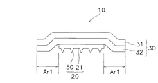
本発明の第1実施形態に係る経皮投与用貼付剤の構造の概要について図1を用いて説明する。図1には、経皮投与用貼付剤の断面構造が模式的に示されている。図1に示されている経皮投与用貼付剤10は、マイクロニードルシート20と透湿性シート30とを備えている。図1の経皮投与用貼付剤10では、透湿性シート30の全面に粘着剤が塗布されて粘着剤層32が形成されている。透湿性シート30は、マイクロニードルシート20を皮膚に貼り付けた状態に維持するための支持部材の役割を果たす。支持部材としての機能を十分に発揮できるように、透湿性シート30は、マイクロニードルシート20よりも一回り大きく形成されている。このような透湿性シート30の略中央にマイクロニードルシート20が貼り付けられると、マイクロニードルシート20の全周に渡ってマイクロニードルシート20の端部から透湿性シート30が外に出た状態になる。この透湿性シート30の外に食み出した領域Ar1に塗られている粘着剤が皮膚に貼り付くことによって、マイクロニードルシート20を皮膚に当接させた状態で経皮投与用貼付剤10が皮膚に貼り付けられる。
<First Embodiment>
(1) Outline of Structure of Transdermal Patch The outline of the structure of the transdermal patch according to the first embodiment of the present invention will be described with reference to FIG. FIG. 1 schematically shows a cross-sectional structure of a transdermal patch. A
(1−1)マイクロニードルシート
マイクロニードルシート20は、シート状基材21と複数のマイクロニードル50とを有している。図1に示されているマイクロニードルシート20では、シート状基材21の裏面が粘着剤層32に貼り付けられ、シート状基材21の表面に複数のマイクロニードル50が形成されている。
シート状基材21は、貼り付けられる皮膚の部位に適する様々な平面形状に成形される。シート状基材21の厚みは、比較的薄く、例えば数百μmである。シート状基材21は、単一の材質で構成された単層構造であっても、異なる材質で形成された多層構造であってもよい。
(1-1) Microneedle Sheet The
The sheet-
シート状基材21の表面層の材質は、マイクロニードル50の材質と同じものであることが好ましいが、複数のマイクロニードル50をシート状基材21の表面に立てた状態で支持できるものであればよい。具体的には、シート状基材21の表面層は、生体に無害な高分子物質で形成される。生体に無害な高分子物質の中には、例えば、生体に無害な樹脂、生体に無害な多糖類及び生体に無害なタンパク質並びにそれらに由来する生体に無害な化合物が含まれる。ここで生体に無害とは、適正な使用方法により皮膚から導入される量が適切に調整されるときに、医療、美容又は獣医学目的に適用可能であることをいう。
The material of the surface layer of the sheet-
マイクロニードル50はシート状基材21の表面層の材質と同じ材質で形成されることが好ましいが、角層に目的物質を導入するのに適した材質がマイクロニードル50の材質として選択される。マイクロニードル50の材質も、生体に無害な高分子物質で形成される。マイクロニードル50の材質としての高分子物質にも、例えば、生体に無害な樹脂、生体に無害な多糖類及び生体に無害なタンパク質並びにそれらに由来する生体に無害な化合物が含まれる。
The microneedle 50 is preferably formed of the same material as that of the surface layer of the sheet-
マイクロニードル50の材質としての生体に無害な高分子物質は、生体内溶解性及び生体内分解性のうちの少なくとも一方の性質を有することが好ましい。ここで、生体内溶解性とは生体内で溶解する性質であり、生体内分解性とは生体内で分解する性質である。両性質のうちの少なくとも一方を有する高分子物質でマイクロニードル50が形成されることにより、皮膚の角層内に侵入したマイクロニードル50は、生体内で溶解及び分解のうちの少なくとも一方の作用を受けて時間の経過とともに徐々に変化するため、固体のままで角層内に長期間残留することはない。 The polymer material that is harmless to the living body as the material of the microneedle 50 preferably has at least one of the properties of in vivo solubility and in vivo degradability. Here, the in vivo solubility is a property that dissolves in vivo, and the in vivo degradability is a property that decomposes in vivo. When the microneedle 50 is formed of a polymer material having at least one of both properties, the microneedle 50 that has entered the stratum corneum of the skin has at least one action of dissolution and decomposition in the living body. Since it changes gradually with the passage of time, it does not remain in the stratum corneum for a long time as a solid.
また、マイクロニードル50を形成する生体内溶解性及び/又は生体内分解性の高分子物質は水溶性であることが好ましい。皮膚の角層に侵入したマイクロニードル50が水溶性高分子物質であれば角層内にある水分でマイクロニードル50が溶解するので、マイクロニードル50を用いて目的物質を角層内にスムーズに導入しやすくなる。
水溶性で且つ生体内溶解性及び生体内分解性のうちの少なくとも一方の性質を有する生体に無害な多糖類及びそれに由来する生体に無害な化合物としては、例えば、マルトース、デキストラン、水溶性キトサン、プルラン、コンドロイチン硫酸ナトリウム、ヒアルロン酸ナトリウム及びグリコーゲンが挙げられる。水溶性で且つ生体内溶解性及び生体内分解性のうちの少なくとも一方の性質を有する生体に無害なタンパク質及びそれに由来する生体に無害な化合物としては、例えば、血清アルブミン及び血清α酸性糖タンパク質が挙げられる。水溶性で且つ生体内溶解性及び生体内分解性のうちの少なくとも一方の性質を有する生体に無害な樹脂及びそれに由来する生体に無害な化合物としては、例えば、水溶性の生体に無害な生分解性ポリマー及びそれに由来する化合物が挙げられる。水溶性の生体に無害な生分解性ポリマー及びそれに由来する化合物としては、例えば、カルボキシビニルポリマー及び、水溶性で生体適合可能なポリマーであるポリエチレングリコール(PEG)と乳酸・グリコール酸−共重合体(PLGA)、ポリカプロラクトン(PCL)又はポリ乳酸(PLA)とをブロック共重合させた水溶性と生分解性とを有するブロックポリマーが挙げられる。
また、非水溶性で且つ生体内溶解性及び生体内分解性のうちの少なくとも一方の性質を有する生体に無害な樹脂及びそれに由来する生体に無害な化合物としては、例えば、ポリ乳酸、ポリグリコール酸及びポリジオキサノンが挙げられる。
上述のマイクロニードル50に用いられる材料は、そのままシート状基材21の材料としても用いることができる。
Moreover, it is preferable that the in-vivo-soluble and / or bio-degradable polymer substance forming the microneedle 50 is water-soluble. If the microneedle 50 that has penetrated into the stratum corneum of the skin is a water-soluble polymer substance, the
Polysaccharides that are water-soluble and have at least one of in vivo solubility and biodegradability and are harmless to the living body and compounds that are harmless to the living body include, for example, maltose, dextran, water-soluble chitosan, Examples include pullulan, sodium chondroitin sulfate, sodium hyaluronate and glycogen. Examples of proteins that are water-soluble and have at least one of in vivo solubility and biodegradability and are harmless to the living body and compounds that are harmless to the living body include serum albumin and serum α-acid glycoprotein. Can be mentioned. Examples of a resin that is water-soluble and has at least one of in vivo solubility and biodegradability and is harmless to a living body and a compound that is harmless to a living body include, for example, biodegradation that is harmless to a water-soluble living body And polymers derived therefrom. Examples of water-soluble biodegradable polymers that are harmless to living bodies and compounds derived therefrom include carboxyvinyl polymers and polyethylene glycol (PEG), which is a water-soluble and biocompatible polymer, and lactic acid / glycolic acid-copolymer. Examples thereof include block polymers having water solubility and biodegradability obtained by block copolymerization of (PLGA), polycaprolactone (PCL), or polylactic acid (PLA).
In addition, as a non-water-soluble resin having at least one of in vivo solubility and biodegradability, a harmless resin that is harmless to a living body and a compound that is harmless to the living body, for example, polylactic acid, polyglycolic acid And polydioxanone.
The material used for the above-described
マイクロニードル50の材質を上述のものとしたときに、角層内に導入する目的物質は、上述の材質と同じものであってもよいが、上述の材質とは異なるものとすることもできる。角層内に導入する目的物質としては、例えば、傷病の治療や診断や予防、美容及び獣医学目的のために用いられる生物活性物質が挙げられる。このような生物活性物質には、例えば、薬物、栄養素及び化粧品が含まれる。マイクロニードル50が後述するような形状を有するため、目的物質としては、特に、角層の美容又は角層の傷病に作用する生物活性物質が好ましく、例えば角層の美容に効果があるヒアルロン酸ナトリウムが挙げられる。
第1実施形態に係るマイクロニードルシート20は例えば全体がヒアルロン酸ナトリウムからなり、マイクロニードル50も例えば全体がヒアルロン酸ナトリウムからなり、第1実施形態に係る経皮投与用貼付剤10は例えば化粧品として顔に貼って顔の皮膚の角層にヒアルロン酸ナトリウムを導入するものである。
なお、マイクロニードル50の形状については後ほど詳細に説明する。
When the material of the microneedle 50 is as described above, the target substance introduced into the stratum corneum may be the same as the above-mentioned material, but may be different from the above-mentioned material. Examples of the target substance to be introduced into the stratum corneum include biologically active substances used for the treatment and diagnosis and prevention of wounds, beauty, and veterinary purposes. Such biologically active substances include, for example, drugs, nutrients and cosmetics. Since the
For example, the
The shape of the microneedle 50 will be described in detail later.
(1−2)透湿性シート
透湿性シート30の基材は、例えば、水蒸気を透過する孔径0.1μmから100μm、好ましくは10μmから30μmまでの多数(複数)の蒸気透過孔(図示せず)を有するポリウレタンフィルム31で形成される。透湿性シート30の厚みは、例えば数十μm程度である。また、透湿性シート30は、皮膚に貼付するための粘着剤層32を有する。透湿性シート30は、ポリウレタンフィルム31及び粘着剤層32の蒸気透過孔から水蒸気を透過させて、透湿性シート30の貼り付けられている箇所の皮膚が蒸れない構成になっている。そのために、例えば、粘着剤層32によって蒸気透過孔を全て塞ぐことがないように塗布面積が少なくなるように疎らに塗布されている。
(1-2) Moisture-permeable sheet The base material of the moisture-
(2)各マイクロニードルの形状
図2は、一つのマイクロニードルとその周辺を部分的に拡大した部分拡大側面図である。図3は、一つのマイクロニードルとその周辺の部分を拡大した部分拡大斜視図である。図2及び図3に示されているように、マイクロニードル50は、皮膚伸張部51と棘状突起部52とを有している。皮膚伸張部51は、シート状基材21から隆起している部分であり、シート状基材21と一体に成形されている。皮膚伸張部51及びシート状基材21は、例えば全体がヒアルロン酸ナトリウムで形成されている。
皮膚伸張部51は、円錐台であり、先端面51aの直径D1が40μm〜250μmの範囲内で設定され、後部断面51bの直径D2が120μm〜700μmの範囲内で設定され、後部断面51bから先端面51aまでの高さH1が30μm〜300μmの範囲内で設定される。先端面51aの直径D1は、皮膚が変形し易いように、60μm〜80μmの範囲内で設定されるのが好ましい。このことを先端面51aの面積で表現すると、先端面51aに掛かる圧力を低くして角層に先端面51aが侵入し難くするためには、棘状突起部52の形成領域も含めて先端面51aの面積が1×10⁻³mm2以上であることが好ましいということになる。
棘状突起部52は、皮膚伸張部51の先端面51aに形成される。棘状突起部52は、先端が細くなった錐状をしており、根元部52bの直径D3が1μm〜24μmの範囲内で設定され、根元部52bから頂部52aまでの高さH2が1μm〜20μmの範囲内で設定される。頂部52aを角層内部に容易に留められるようにするために、根元部52bの直径D3が5μm〜18μmの範囲内で設定され、根元部52bから頂部52aまでの高さH2が5μm〜18μmの範囲内で設定されることが好ましい。
棘状突起部52の根元部52bの水平断面(シート状基材21の表面に平行な断面)の形状は、少なくとも根元部52bから皮膚伸張部51の先端面51aの端部51aaまでの長さL1が8μm〜20μmの範囲内に納まるような大きさに設定される。なお、一つの先端面51aに形成される棘状突起部52の個数は、複数であってもよいが、角層に確実に侵入させるためには1個が好ましい。棘状突起部52の根元部52bの面積つまり棘状突起部52の平面視における面積で表すと、棘状突起部52に掛かる圧力を高くして角層に頂部52aが侵入し易くするためには、平面視における面積が5×10⁻⁴mm2未満であることが好ましい。
(2) Shape of each microneedle FIG. 2 is a partially enlarged side view in which one microneedle and its periphery are partially enlarged. FIG. 3 is a partially enlarged perspective view in which one microneedle and a peripheral portion thereof are enlarged. As shown in FIGS. 2 and 3, the
The
The
The shape of the horizontal cross section (the cross section parallel to the surface of the sheet-like base material 21) of the
上述のような大きさに設定された皮膚伸張部51は、粘着剤層32によって経皮投与用貼付剤10が通常の人間の皮膚に貼り付けられた場合に、皮膚伸張部51の先端面51aが皮膚の角層内に侵入しない構成である。言い換えれば、上述のような大きさに設定された皮膚伸張部51の形状であれば、経皮投与用貼付剤10が皮膚に貼り付けられた際に、皮膚伸張部51の周囲の皮膚が伸びて皮膚表面がシート状基材21の表面に達するということである。
上述のような大きさに設定された棘状突起部52は、粘着剤層32によって経皮投与用貼付剤10が通常の人間の皮膚に貼り付けられた場合に、棘状突起部52の全体が皮膚の角層内に侵入しても棘状突起部52の頂部52aが角層を突き抜けない構成である。言い換えれば、上述のような大きさに設定された棘状突起部52の形状であれば、皮膚表面がシート状基材21の表面に達する状態では、棘状突起部52の少なくとも頂部52aが角層内に留まっているということである。
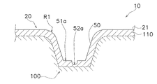
図4には、経皮投与用貼付剤10が人間の皮膚100に貼り付けられたときの一つのマイクロニードル50と皮膚100との関係が模式的に示されている。図4に示されている断面から分かるように、角層110には皮膚伸張部51が侵入しておらず、棘状突起部52だけが角層110の内部に侵入している。そして、棘状突起部52の頂部52aは角層110の内部に在る。
The
The
FIG. 4 schematically shows the relationship between one
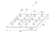
(3)マイクロニードルの配置
複数のマイクロニードル50は、例えば、図5に示されているように格子状に配列される。複数のマイクロニードル50の配列は、格子状に限られるものではないが、全体に均一に配置されることが好ましい。マイクロニードル50の配置に偏りが在ると、比較的高い圧力が掛かる部分と比較的低い圧力が掛かる部分ができてしまうからである。比較的高い圧力の部分と比較的低い圧力の部分の圧力差が大きくなり過ぎると、棘状突起部52が角層に刺さらない領域が生じたり、逆に皮膚伸張部51が角層に刺さってしまう領域が生じたりするからである。
経皮投与用貼付剤10を貼り付けるときには、先ず棘状突起部52が皮膚100の角層110に当たるので、複数の棘状突起部52が角層110に侵入しやすくするためには、各棘状突起部52に高い圧力が印加されることが好ましい。具体的には、単位面積当たりに配置される根元部52bの面積の総計が、0.2%以下(図5においては0.002×UL2以下)になるように配置されることが好ましい。例えば、根元部52bが円形でかつほぼ平坦で直径D3が24μmとすると、1cm2当たり400本以下配置すればよい。この場合の根元部52bのおよその総面積を計算すると、3.14×12μm×12μm×400≒0.18mm2になり、0.18mm2/100mm2×100=0.18%となって0.2%以下という条件を満足する。根元部52bが矩形であれば、例えば、根元部52bの一辺が20μmの棘状突起部52を1cm2当たり500本以下配置すればよい。
(3) Arrangement of microneedles The plurality of
When the
また、複数の皮膚伸張部51を角層に侵入させないようにするためには、経皮投与用貼付剤10を貼り付けるときには、先ず棘状突起部52が皮膚100の角層110に当たった後に皮膚伸張部51の先端面51aが当たるので、できるだけ多くの皮膚伸張部51に、皮膚が変形する際の圧力を分散することが好ましい。具体的には、単位面積当たりの先端面51aの面積の総計が、単位面積の0.3%以上(例えば図5においては0.003×UL2以上)になるように配置されることが好ましい。例えば、先端面51aが円形でかつほぼ平坦で直径D1が40μmとすると、1cm2当たり250本以上配置すればよい。この場合の先端面51aのおよその総面積を計算すると、3.14×20μm×20μm×250≒0.31mm2になり、0.31mm2/100mm2×100=0.31%となって、単位面積の0.3%以上という条件を満足する。
また、既に説明したように、皮膚が変形する際の圧力を小さくするために、先端面51aの直径D1が40μm〜250μmの範囲内で設定される。さらに、皮膚を十分に伸張させるために、後部断面51bから先端面51aまでの高さH1が30μm〜300μmの範囲内で設定される。
In order to prevent the plurality of
Further, as already described, in order to reduce the pressure when the skin is deformed, the diameter D1 of the
例えば、図5の一点鎖線の円とマイクロニードル50の後部断面51bとで囲まれた領域Ar2は、皮膚100に経皮投与用貼付剤10を貼り付けるときに、皮膚100に接触しない領域である。経皮投与用貼付剤10に高い圧力が掛かる場合でも角層110が皮膚伸張部51によって損壊するのを防止するために、このような非接触の領域Ar2は、0.5MPaの圧力がマイクロニードルシート20に印加されているときに総面積が単位面積の0.3%以下(例えば図5においては0.003×UL2以下)であることが好ましい。そのためには、互いに隣接する前記皮膚伸張部と前記シート状基材との境界間の間隔が互いに隣接する前記皮膚伸張部の高さの2乗を100で割った値よりも離れるように配置されていることが好ましい。この点については後ほど図7乃至図9を用いて詳しく説明する。また、皮膚伸張部51の側面51cの傾きを緩やかにすることが好ましく、後部断面51bの直径D2が先端面51aの直径D1の差が100μm以上であることが好ましい。
さらに、約0.13MPaの圧力を印加したときに、図4に示されているように、皮膚100の表面がほぼマイクロニードル50及びシート状基材21の表面に密着する形状にマイクロニードル50が形成されている。このとき皮膚100との密着を良くするために、後部断面51bの裾の部分の曲率半径R1が0.1mm以下0.01mm以上であることが好ましく、0.05mm以下であることがさらに好ましい。
このように皮膚100がシート状基材21に密着する部分が多くなるので、シート状基材21から皮膚100への経皮投与も考慮してマイクロニードル50とシート状基材21が同じ材質で構成されることが好ましい。
For example, the area Ar2 surrounded by the one-dot chain circle in FIG. 5 and the
Furthermore, when a pressure of about 0.13 MPa is applied, the
Thus, since the part where
(4)マイクロニードルシートの製造方法
マイクロニードルシート20は、複数のマイクロニードル50の形状が彫られた型であるスタンパー(図示せず)にヒアルロン酸ナトリウムの水溶液を流し込んだ後に乾燥されることにより製造される。ヒアルロン酸ナトリウムが投与の目的物質であれば、ヒアルロン酸ナトリウムの水溶液を主な成分としてマイクロニードルシート20が形成されてもよい。また目的物質が例えばヒアルロン酸ナトリウムと他の生物活性物質の場合には、他の生物活性物質の添加されたヒアルロン酸ナトリウムの水溶液がスタンパーに流し込まれて乾燥されるようにして、マイクロニードルシート20が製造されてもよい。さらには、目的物質の安定化剤など目的物質以外の他も物質が添加されてもよい。また、ヒアルロン酸ナトリウムの他の生物活性物質の添加方法として、上記以外の方法を用いてもよく、例えば乾燥後に塗布することで添加することもできる。
上述の製造方法により、例えばヒアルロン酸ナトリウムからなるマイクロニードル50が1cm当たり250本形成されているマイクロニードルシート20が製造できる。このマイクロニードルシート20は、先端面51aの直径D1が68μm、後部断面51bの直径D2が200μm、高さH1が100μmの皮膚伸張部51と、根元部52bの直径D3が20μm、高さH2が15μm、長さL1が8μmの棘状突起部52とを有している。
(4) Manufacturing method of microneedle sheet The
By the above manufacturing method, for example, the
(5)特徴
図6(a)は、シート状基材21の上に棘状突起部252を形成したものを皮膚100に当接させる直前の状態を示した模式的断面図である。図6(a)に示されているように、棘状突起部252を平らなシート状基材21の上に直接形成した場合、非常に微細な棘状突起部252だけでは、皮膚100の凸凹やうねりや皮膚構造などに起因して皮膚100が伸びるため角層110に上手く刺さらない場面あるいは凹凸やうねりによって皮膚100の表面に接触しない場面が生じてしまう。
それに対して、図4に示した皮膚伸張部51があると、皮膚伸張部51によって皮膚100が伸びきった状態になって経皮投与用貼付剤10を貼付する前に比べて皮膚100の伸び率が減少するため、高さが1μmから20μmという微細な棘状突起部52でもその頂部52aが角層110の内部にまで侵入する。
その結果、シート状基材21の表面並びに皮膚伸張部51の先端面51a及び側面51cからヒアルロン酸ナトリウムが角層110に供給されるだけでなく、棘状突起部52からも角層110にヒアルロン酸ナトリウムが供給され、棘状突起部52を有しない皮膚伸張部51だけの場合に比べて、角層110に供給されるヒアルロン酸ナトリウムの量を増やすことができる。
(5) Features FIG. 6A is a schematic cross-sectional view showing a state immediately before the
On the other hand, when there is the skin stretched
As a result, not only sodium hyaluronate is supplied to the
一方、経皮投与用貼付剤10を使用するとき、例えば就寝中でも経皮投与用貼付剤10を粘着剤層32(押圧部の例)によって皮膚に貼ったままの状態にする状況が頻繁に発生する。就寝中は、経皮投与用貼付剤10を使用している使用者が経皮投与用貼付剤10を無意識に寝具や周囲の器物などに当ててしまって経皮投与用貼付剤10に高い圧力が掛かることが予想される。もし、図6(b)及び図6(c)に示されているように、皮膚伸張部261を高くしすぎると皮膚伸張部261やシート状基材21の表面と皮膚100とが接触しない領域Ar3が大きくなり過ぎ、このようなマイクロニードル260の先端面261aに高い圧力が掛かってしまう状況が生じて先端面261aで角層110を破る場合が発生する可能性が高くなる。
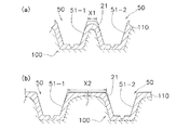
上述の第1実施形態のマイクロニードル50は、図7(b)に記載されているように、互いに隣接する皮膚伸張部51−1,51−2とシート状基材21との境界間の間隔X2が互いに隣接する皮膚伸張部の高さH1の2乗を100で割った値よりも離れるように配置され、つまり、X2≧(H1×H1)÷100だけ離れて配置されている。角層110がシート状基材21に接触しない非接触の領域Ar2は、500gf/cm2の圧力がマイクロニードルシート20に印加されているときに総面積が単位面積の0.3%以下(例えば図5においては0.003×UL2以下)になるように構成されている。また、皮膚伸張部51の側面51cの傾きを緩やかにするため、後部断面51bの直径D2が先端面51aの直径D1の差が132μm(≧100μm)に設定されている。
もし、図7(a)のように皮膚伸張部51−1,51−2とシート状基材21との境界間の間隔X1(<<X2)が小さいと、角層110がシート状基材21に接触しない領域が多くなり、マイクロニードルシート20に高い圧力が掛かったときにマイクロニードル50が角層110を突き破って貫通する可能性が高くなる。
図8には、ヒアルロン酸ナトリウムで形成されたマイクロニードルシート20について、マイクロニードル50の形状とマイクロニードルシート20の皮膚100の角層110への密着との関係を示す例が記載されている。図8において、「皮膚との密着」の列に記載されている「○」は皮膚との密着が良好であることを示しており、「×」は皮膚との密着が不良であることを示しており、「△」は皮膚との密着があまり良くないことを示している。なお、図8に示されているニードル形状NS4,NS5,NS6については、角層110に皮膚伸張部51が刺さるものが見られた。角層110に皮膚伸張部51が刺さると角層110とシート状基材21との距離が近くなるのであるが、それでも角層110との密着が良好ではなかったので、ニードル形状NS4,NS5,NS6を密着の良くない例として記載している。
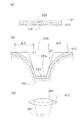
ところで、皮膚伸張部51の高さが「0μm」であれば角層110にシート状基材21が密着することから、図9のグラフに示されているように、密着が良好な範囲を示す直線LLはグラフの原点を通ると考えられる。そして、皮膚伸張部51の高さの範囲が30μm〜300μmのような狭い範囲においては、この線LLを直線として近似しても問題ないと考えられる。そこで、原点を通り、密着が良好なものとあまり良くないものの間を通る直線を引くと、図9のようなグラフが得られる。この直線LLから、(互いに隣接するマイクロニードル50の間の空間)≧(マイクロニードル50の高さの2乗)÷100という条件を満たすと、角層110に対して密着の良いマイクロニードルシート20が得られることが分かる。なお、ここでいう「互いに隣接するマイクロニードル50の間の空間」とは、図7(b)に示されている「互いに隣接する皮膚伸張部51−1,51−2とシート状基材21との境界間の間隔X2」のことである。
なお、マイクロニードル50の間の空間が広がれば1本のマイクロニードル50に掛かる圧力が大きくなるので、マイクロニードル50の高さを高くしてそれらの間の空間を広げるよりも、マイクロニードル50の高さを低くしてそれらの間の空間を狭めた方が好ましい。このような観点から図9を見ると、マイクロニードル50の高さの2乗は、40000以下であることが好ましいと考えられる。また、互いに隣接するマイクロニードル50の高さが異なって、高いものと低いものがある場合には、高いものに合わせる。
また、角層110とマイクロニードルシート20との密着具合や皮膚伸張部51による角層110の損傷や棘状突起部52の角層110への侵入は、実際に皮膚に貼り付いた部分のマイクロニードルシート20の光学観察装置による拡大像を用いた観察により評価した。
On the other hand, when the
As described in FIG. 7B, the microneedle 50 according to the first embodiment described above is an interval between the boundaries between the adjacent skin extension portions 51-1 and 51-2 and the sheet-
If the interval X1 (<< X2) between the boundaries between the skin extension portions 51-1 and 51-2 and the sheet-
FIG. 8 shows an example of the relationship between the shape of the microneedle 50 and the adhesion of the
By the way, if the height of the skin stretched
In addition, since the pressure applied to one
In addition, the degree of contact between the
さらに、後部断面51bの裾の部分の曲率半径R1が5μm(≧3μm)に設定されているので、約0.13MPaの圧力を印加したときに、皮膚100の表面がほぼマイクロニードル50及びシート状基材21の表面に密着する形状にマイクロニードル50が形成され、皮膚100との密着が良くなる。
複数のマイクロニードル50が形成された直径10mmの円盤に10Nの力を加えたとき、言い換えると約0.13MPaの圧力を印加したときに、図5に示されているように、皮膚100の表面がほぼマイクロニードル50及びシート状基材21の表面に密着する形状にマイクロニードル50が形成されている。マイクロニードル50がこのような形状を有するために、0.13MPaよりも高い圧力がマイクロニードルシート20に印加されても、ほとんどの圧力がシート状基材21に掛かって先端面51aに応力が集中することがないので、先端面51aで角層110が破られることは防止される。
また、皮膚100がシート状基材21に密着する部分を多くする場合には、シート状基材21から皮膚100への経皮投与も考慮してマイクロニードル50とシート状基材21が同じ材質で構成されることが好ましい。例えば美容目的で皮膚100にできるだけ多くのヒアルロン酸ナトリウムを投与したいときにはシート状基材21がヒアルロン酸ナトリウムで形成されていると効果的である。
Furthermore, since the curvature radius R1 of the skirt portion of the
When a force of 10 N is applied to a disk having a diameter of 10 mm in which a plurality of
Further, when the portion where the
(6)変形例
(6−1)変形例1A
上記第1実施形態ではマイクロニードルシート20がヒアルロン酸ナトリウムで形成されている場合を例に挙げて説明したが、マイクロニードルシート20を例えば第1実施形態とは異なる熱可塑性プラスチックで形成することもできる。そのような場合のマイクロニードルシートは、複数のマイクロニードル50と同じ形状が彫られた型に射出成形して製造されてもよい。目的物質が熱可塑性プラスチックでない場合に、目的物質が熱によって変性しないものであれば熱可塑性プラスチックに混ぜて射出成形を行うことができ、射出成型後に塗布などの手段によって目的物質が成形後の熱可塑性プラスチックに添加されてもよい。目的物質が熱に弱いものや高価なものであれば、射出成型後に塗布することにより例えば目的物質を添加する際のコストを抑えることができる。
例えば、図10に示されている経皮投与用貼付剤10Aのマイクロニードルシート20Aのように、例えば熱可塑性プラスチックであるポリ乳酸でシート状基材21Aとマイクロニードル50Aを形成して、その上にヒアルロン酸ナトリウムの層53をコーティングしてもよい。このとき、マイクロニードル50Aの皮膚伸張部51及び棘状突起部52もポリ乳酸で形成される。この場合には、ヒアルロン酸ナトリウムのマイクロニードル50のように水に溶けないため、皮膚100に貼り付けてもマイクロニードル50Aにその形状を維持させることができる。
(6) Modification (6-1) Modification 1A
In the first embodiment, the case where the
For example, like the
(6−2)変形例1B
上記第1実施形態では、目的物質がヒアルロン酸ナトリウムである場合に、マイクロニードルシート20がヒアルロン酸ナトリウムで形成される場合を例に挙げて説明したが、例えば目的物質が薬剤である場合には、ヒアルロン酸ナトリウムで形成されるマイクロニードルシート20に薬剤が添加されてもよく、あるいはマイクロニードルシート20に薬剤がコーティングされてもよい。
(6−3)変形例1C
上記実施形態の説明では、マイクロニードルシート20を皮膚100に押圧した状態を維持させる押圧部として、マイクロニードルシート20を覆う透湿性シート30に形成されている粘着剤層32を例に挙げて説明したが、押圧部はこのような形態の粘着剤に限られるものではない。例えば、マイクロニードルシート20のシート状基材21の表面、すなわちマイクロニードル50が形成されている面に形成された粘着剤や接着剤を押圧部とすることもできる。また、押圧部は、マイクロニードルシート20を皮膚100に密着させた状態でマイクロニードルシート20を人体に巻きとめる包帯であってもよい。包帯の場合には、マイクロニードルシート20に接触する部分にクッション部材を設けて押圧力を高めるように構成してもよい。また、眼帯のように、あて布の両端に紐又はゴムなどの紐状部材がついており、紐状部材で身体にくくり付けたり、紐状部材を身体に引っ掛けたりするもののあて布の部分にマイクロニードルシート20と取り付けるようにしてもよい。
(6-2) Modification 1B
In the first embodiment, the case where the target substance is sodium hyaluronate and the
(6-3) Modification 1C
In the description of the above embodiment, the pressure-
<第2実施形態>
(7)経皮投与用貼付剤の構造の概要
図11乃至図13を用いて第2実施形態に係る経皮投与用貼付剤10Bについて説明する。図11は、一つのマイクロニードルとその周辺を部分的に拡大した部分拡大側面図である。図12は、一つのマイクロニードルとその周辺の部分を拡大した部分拡大斜視図である。図11及び図12に示されているように、第2実施形態に係る経皮投与用貼付剤10Bは、マイクロニードル50Bが皮膚伸張部51を有している。しかし、上記第1実施形態に係る経皮投与用貼付剤10とは異なり、皮膚伸張部51の先端面51aには棘状突起部が形成されてない。第2実施形態に係る経皮投与用貼付剤10Bは、複数のマイクロニードル50Bの形状及び配置以外は第1実施形態の経皮投与用貼付剤10と同様に構成できるので、以下においては第2実施形態に係る経皮投与用貼付剤10Bのマイクロニードル50Bの形状及び配置について説明してその他の説明を省略する。
Second Embodiment
(7) Outline of structure of transdermal patch The
(8)各マイクロニードルの形状
図11及び図12に示されているように、マイクロニードル50Bは、シート状基材21から隆起している皮膚伸張部51を有しており、シート状基材21と一体に成形されている。皮膚伸張部51及びシート状基材21は、例えば全体がヒアルロン酸ナトリウムで形成されている。
皮膚伸張部51は、円錐台であり、先端面51aの直径D1が40μm〜250μmの範囲内で設定され、後部断面51bの直径D2が120μm〜700μmの範囲内で設定され、後部断面51bから先端面51aまでの高さH1が30μm〜300μmの範囲内で設定される。先端面51aの直径D1は、皮膚が変形し易いように、60μm〜80μmの範囲内で設定されるのが好ましい。このことを先端面51aの面積で表現すると、先端面51aに掛かる圧力を低くして角層に先端面51aが侵入し難くするためには、先端面51aの面積が1×10⁻³mm2以上であることが好ましいといことになる。
(8) Shape of Each Microneedle As shown in FIG. 11 and FIG. 12, the
The
上述のような大きさに設定された皮膚伸張部51は、経皮投与用貼付剤10Bが通常の人間の皮膚に貼り付けられた場合に、皮膚伸張部51の先端面51aが皮膚の角層内に侵入しない構成である。言い換えれば、上述のような大きさに設定された皮膚伸張部51の形状であれば、経皮投与用貼付剤10Bが皮膚に貼り付けられた際に、皮膚伸張部51の周囲の皮膚が伸びて皮膚表面がシート状基材21の表面に達するということである。
図13には、経皮投与用貼付剤10Bが人間の皮膚100に貼り付けられたときの一つのマイクロニードル50Bと皮膚100との関係が模式的に示されている。図13に示されている断面から分かるように、角層110には皮膚伸張部51が侵入しないで、その周囲の角層110を伸張させているだけである。
The skin stretched
FIG. 13 schematically shows a relationship between one
(9)マイクロニードルの配置
複数のマイクロニードル50Bは、例えば、図5に示されているマイクロニードル50と同じように格子状に配列される。複数のマイクロニードル50Bの配列は、格子状に限られるものではないが、全体に均一に配置されることが好ましい。マイクロニードル50Bの配置に偏りが在ると、比較的高い圧力が掛かる部分と比較的低い圧力が掛かる部分ができてしまうからである。比較的高い圧力の部分と比較的低い圧力の部分の圧力差が大きくなり過ぎると、皮膚伸張部51が角層に刺さってしまう領域が生じたりするからである。
(9) Arrangement of microneedles The plurality of
複数の皮膚伸張部51を角層に侵入させないようにするためには、経皮投与用貼付剤10Bを貼り付けるときには、先ず皮膚100の角層110に皮膚伸張部51の先端面51aが当たるので、できるだけ多くの皮膚伸張部51に皮膚が変形する際の圧力を分散することが好ましい。具体的には、単位面積当たりの先端面51aの面積の総計が、単位面積の0.3%以上(例えば図5においては0.003×UL2以上)になるように配置されることが好ましい。
In order to prevent a plurality of
上述の第2実施形態のマイクロニードル50Bは、互いに隣接する皮膚伸張部51とシート状基材21との境界間の間隔が互いに隣接する皮膚伸張部の高さの2乗を100で割った値よりも離れるように配置され、上述の例では200μm以上(H1×2)だけ離れて配置されている。そのような構成により、角層110がシート状基材21に接触しない非接触の領域Ar2は、500gf/cm2の圧力がマイクロニードルシート20に印加されているときに総面積が単位面積の0.3%以下(例えば図5においては0.003×UL2以下)になる。その結果、経皮投与用貼付剤10Bに高い圧力が掛かる場合でも角層110が皮膚伸張部51によって損壊するのを防止することができる。また、皮膚伸張部51の側面51cの傾きを緩やかにするため、後部断面51bの直径D2が先端面51aの直径D1の差が132μm(≧100μm)に設定されている。側面51cの傾きを緩やかにすることにより、マイクロニードルシート20Bに高い圧力が掛かったときにマイクロニードル50Bが角層110を突き破って貫通する可能性が低くなる。
さらに、後部断面51bの裾の部分の曲率半径R1が0.05mmに設定されているので、約0.13MPaの圧力を印加したときに、皮膚100の表面がほぼマイクロニードル50B及びシート状基材21の表面に密着する形状にマイクロニードル50Bが形成され、皮膚100との密着が良くなる。
In the microneedle 50B of the second embodiment described above, a value obtained by dividing the square of the height of the adjacent skin extension portions by 100 by the distance between the boundaries between the adjacent
Further, since the radius of curvature R1 of the skirt portion of the
第2実施形態の複数のマイクロニードル50Bは、約0.13MPaの圧力を印加したときに、皮膚100の表面がほぼマイクロニードル50B及びシート状基材21の表面に密着する形状に形成されている。マイクロニードル50Bがこのような形状を有するために、0.13MPaよりも高い圧力がマイクロニードルシート20Bに印加されても、ほとんどの圧力がシート状基材21に掛かって先端面51aに応力が集中することがないので、先端面51aで角層110が破られることは防止される。
このように皮膚100がシート状基材21に密着する部分が多くなるので、シート状基材21から皮膚100への経皮投与も考慮してマイクロニードル50Bとシート状基材21が同じ材質で構成されることが好ましい。
The plurality of
Thus, since the part where
(10)特徴
上述の第2実施形態のマイクロニードル50Bは、複数のマイクロニードル50Bが形成された直径10mmの円盤に10Nの力を加えたとき、言い換えると約0.13MPaの圧力を印加したときに、皮膚100の表面がほぼマイクロニードル50B及びシート状基材21の表面に密着する形状にマイクロニードル50Bが形成されている。マイクロニードル50Bがこのような形状を有するために、0.13MPaよりも高い圧力がマイクロニードルシート20に印加されても、ほとんどの圧力がシート状基材21に掛かって先端面51aに応力が集中することがないので、先端面51aで角層110が破られることは防止される。
また、皮膚100がシート状基材21に密着する部分を多くする場合には、シート状基材21から皮膚100への経皮投与も考慮してマイクロニードル50Bとシート状基材21が同じ材質で構成されることが好ましい。例えば美容目的で皮膚100にできるだけ多くのヒアルロン酸ナトリウムを投与したいときにはシート状基材21がヒアルロン酸ナトリウムで形成されていると効果的である。
上述のように、シート状基材21の表面並びに皮膚伸張部51を形成したマイクロニードルシート20Bとシート状基材21のみからなるものを皮膚に貼り付けて比較すると、皮膚伸張部51の先端面51a及び側面51cからヒアルロン酸ナトリウムが角層110に供給されるので、シート状基材21のみからヒアルロン酸ナトリウムが角層110に供給されるシート状基材21のみからなるものよりもマイクロニードルシート20Bの方が角層110に供給されるヒアルロン酸ナトリウムの量が増える。
(10) Features The microneedle 50B of the second embodiment described above is when a force of 10 N is applied to a disk having a diameter of 10 mm on which a plurality of
Further, when the portion where the
As described above, when the surface of the sheet-
(11)変形例
(11−1)変形例2A
上記第2実施形態ではマイクロニードルシート20Bがヒアルロン酸ナトリウムで形成されている場合を例に挙げて説明したが、マイクロニードルシート20Bを例えば第1実施形態とは異なる熱可塑性プラスチックで形成することもできる。そのような場合のマイクロニードルシートは、複数のマイクロニードル50Bと同じ形状が彫られた型に射出成形して製造されてもよい。目的物質が熱可塑性プラスチックでない場合に、目的物質が熱によって変性しないものであれば熱可塑性プラスチックに混ぜて射出成形を行うことができ、射出成型後に塗布などの手段によって目的物質が成形後の熱可塑性プラスチックに添加されてもよい。目的物質が熱に弱いものや高価なものであれば、射出成型後に塗布することにより例えば目的物質を添加する際のコストを抑えることができる。例えば、図7に示されている経皮投与用貼付剤10Aから棘状突起部52を取り除いた構成とすることができる。
(11) Modification (11-1) Modification 2A
In the second embodiment, the case where the
(11−2)変形例2B
上記第2実施形態では、目的物質が人の皮膚の美容に用いられるヒアルロン酸ナトリウムである場合に、マイクロニードルシート20Bがヒアルロン酸ナトリウムで形成される場合を例に挙げて説明したが、例えば目的物質が薬剤である場合には、ヒアルロン酸ナトリウムで形成されるマイクロニードルシート20Bに薬剤が添加されてもよく、あるいはマイクロニードルシート20Bに薬剤がコーティングされてもよい。
(11−3)変形例2C
上記第1実施形態と同様に、マイクロニードルシート20Bを皮膚100に押圧した状態を維持させる押圧部として、マイクロニードルシート20Bを覆う透湿性シート30に粘着剤層32が形成されているものを用いることができるが、押圧部はこのような形態の粘着剤に限られるものではない。例えば、マイクロニードルシート20Bのシート状基材21の表面、すなわちマイクロニードル50Bが形成されている面に形成された粘着剤や接着剤を押圧部とすることもできる。また、押圧部は、マイクロニードルシート20Bを皮膚100に密着させた状態でマイクロニードルシート20Bを人体に巻きとめる包帯であってもよい。包帯の場合には、マイクロニードルシート20Bに接触する部分にクッション部材を設けて押圧力を高めるように構成してもよい。また、眼帯のように、あて布の両端に紐又はゴムなどの紐状部材がついており、紐状部材で身体にくくり付けたり、紐状部材を身体に引っ掛けたりするもののあて布の部分にマイクロニードルシート20Bと取り付けるようにしてもよい。
(11-2) Modification 2B
In the second embodiment, the case where the target substance is sodium hyaluronate used for the beauty of human skin is described as an example in which the
(11-3) Modification 2C
As in the first embodiment, as the pressing portion that maintains the state in which the
10,10A,10B 経皮投与用貼付剤
20,20A,20B マイクロニードルシート
21,21A シート状基材
30 透湿性シート
31 ポリウレタンフィルム
32 粘着剤層
50,50A,50B マイクロニードル
51 皮膚伸張部
52 棘状突起部
10, 10A,
Claims (7)
複数の前記マイクロニードルの各々は、皮膚の角層の表面に刺さらずに角層の表面を押圧して角層を伸張するため前記シート状基材から隆起した皮膚伸張部を持ち、
前記皮膚伸張部は、面積が1×10⁻³mm2以上であり且つ前記シート状基材の表面からの高さが30μm以上300μm以下の先端面を持ち、互いに隣接する前記皮膚伸張部と前記シート状基材との境界間の間隔が、互いに隣接する前記皮膚伸張部の高さの2乗を100で割った値(μm)よりも離れるように配置され、
前記先端面は、マイクロニードルシートを皮膚に貼り付けるときに皮膚の角層の表面に当たる面であり、直径が40μm以上250μm以下であり、
複数の前記マイクロニードルは、単位面積当たりに前記先端面の占める面積が0.3%以上になる密度で配置されている、マイクロニードルシート。 A microneedle sheet comprising a target substance to be introduced into the horny layer of skin, and having a sheet-like base material and a plurality of microneedles formed on the sheet-like base material and in contact with the horny layer of the skin,
Each of the plurality of microneedles has a skin extension portion raised from the sheet-like base material in order to extend the stratum corneum by pressing the surface of the stratum corneum without piercing the surface of the stratum corneum of the skin,
The skin stretch portion has a tip surface with an area of 1 × 10 −3 mm 2 or more and a height from the surface of the sheet-like base material of 30 μm or more and 300 μm or less, and the skin stretch portion adjacent to each other and the distance between the boundary between the sheet-like substrate is disposed the square height of said skin tensioning portions adjacent to each other away than the value obtained by dividing ([mu] m) at 100,
The tip surface is a surface that hits the surface of the stratum corneum of the skin when the microneedle sheet is applied to the skin, and has a diameter of 40 μm or more and 250 μm or less,
The microneedle sheet, wherein the plurality of microneedles are arranged at a density such that an area occupied by the tip surface per unit area is 0.3% or more.
複数の前記マイクロニードルの各々は、
皮膚の角層の表面に刺さらずに角層の表面を押圧して角層を伸張するための先端面を持つように前記シート状基材から隆起した皮膚伸張部と、
前記皮膚伸張部の前記先端面に形成され、角層の表面に刺さり且つ頂部が角層内部に留まる形状を持つ棘状突起部とを有し、
前記先端面は、マイクロニードルシートを皮膚に貼り付けるときに皮膚の角層の表面に当たる面であり、直径が40μm以上250μm以下であり、
複数の前記マイクロニードルは、単位面積当たりに前記先端面の占める面積が0.3%以上になる密度で配置されている、マイクロニードルシート。 A microneedle sheet comprising a target substance to be introduced into the horny layer of skin, and having a sheet-like base material and a plurality of microneedles formed on the sheet-like base material and in contact with the horny layer of the skin,
Each of the plurality of microneedles is
A skin stretched portion raised from the sheet-like substrate so as to have a distal end surface for stretching the stratum corneum by pressing the stratum corneum surface without piercing the stratum corneum surface of the skin;
A spinous protrusion formed on the distal end surface of the skin extension portion, having a shape that pierces the surface of the stratum corneum and the top portion stays inside the stratum corneum,
The tip surface is a surface that hits the surface of the stratum corneum of the skin when the microneedle sheet is applied to the skin, and has a diameter of 40 μm or more and 250 μm or less,
The microneedle sheet, wherein the plurality of microneedles are arranged at a density such that an area occupied by the tip surface per unit area is 0.3% or more.
請求項2に記載のマイクロニードルシート。 The spinous protrusion has an area in plan view of less than 5 × 10 −4 mm 2 and a height of 1 μm or more and 20 μm or less.
The microneedle sheet according to claim 2.
請求項3に記載のマイクロニードルシート。 The plurality of microneedles are arranged at a density such that the area occupied by the spinous protrusion per unit area is 0.2% or less,
The microneedle sheet according to claim 3.
請求項2から4のいずれか一項に記載のマイクロニードルシート。 The skin extension part has an area of the tip surface of 1 × 10 −3 mm 2 or more, a height from the surface of the sheet-like base material to the tip surface of 30 μm or more and 300 μm or less, and adjacent to each other. spacing between the boundaries of the skin stretching unit and the sheet-like substrate is disposed the square height of said skin tensioning portions adjacent to each other away than the value obtained by dividing ([mu] m) at 100,
The microneedle sheet according to any one of claims 2 to 4.
請求項5に記載のマイクロニードルシート。 The skin extension part has a length from the root of the spinous process part to the end part of the tip surface of 8 μm or more and 20 μm or less.
The microneedle sheet according to claim 5.
前記マイクロニードルシートを皮膚に押圧した状態を維持させる押圧部とを備えた、経皮投与用貼付剤。 The microneedle sheet according to any one of claims 1 to 6,
A patch for transdermal administration, comprising a pressing portion that maintains a state where the microneedle sheet is pressed against the skin.
Priority Applications (6)
| Application Number | Priority Date | Filing Date | Title |
|---|---|---|---|
| JP2014119370A JP6023752B2 (en) | 2014-06-10 | 2014-06-10 | Microneedle sheet and patch for transdermal administration |
| KR1020167034984A KR102167464B1 (en) | 2014-06-10 | 2015-06-02 | Microneedle sheet and dermal administration plaster |
| EP15806520.1A EP3156097A1 (en) | 2014-06-10 | 2015-06-02 | Microneedle sheet and dermal administration plaster |
| PCT/JP2015/065842 WO2015190344A1 (en) | 2014-06-10 | 2015-06-02 | Microneedle sheet and dermal administration plaster |
| CN201580031084.8A CN106456955B (en) | 2014-06-10 | 2015-06-02 | Micropin piece and percutaneous dosing adhesive preparation |
| US15/317,906 US20170106180A1 (en) | 2014-06-10 | 2015-06-02 | Microneedle sheet and transdermal patch |
Applications Claiming Priority (1)
| Application Number | Priority Date | Filing Date | Title |
|---|---|---|---|
| JP2014119370A JP6023752B2 (en) | 2014-06-10 | 2014-06-10 | Microneedle sheet and patch for transdermal administration |
Publications (3)
| Publication Number | Publication Date |
|---|---|
| JP2015231466A JP2015231466A (en) | 2015-12-24 |
| JP2015231466A5 JP2015231466A5 (en) | 2016-07-07 |
| JP6023752B2 true JP6023752B2 (en) | 2016-11-09 |
Family
ID=54833440
Family Applications (1)
| Application Number | Title | Priority Date | Filing Date |
|---|---|---|---|
| JP2014119370A Active JP6023752B2 (en) | 2014-06-10 | 2014-06-10 | Microneedle sheet and patch for transdermal administration |
Country Status (6)
| Country | Link |
|---|---|
| US (1) | US20170106180A1 (en) |
| EP (1) | EP3156097A1 (en) |
| JP (1) | JP6023752B2 (en) |
| KR (1) | KR102167464B1 (en) |
| CN (1) | CN106456955B (en) |
| WO (1) | WO2015190344A1 (en) |
Families Citing this family (5)
| Publication number | Priority date | Publication date | Assignee | Title |
|---|---|---|---|---|
| WO2020044853A1 (en) * | 2018-08-28 | 2020-03-05 | Nissha株式会社 | Skin quality-improving sheet |
| WO2020092229A1 (en) * | 2018-10-31 | 2020-05-07 | The Regents Of The University Of California | Biodegradable microneedles for transdermal therapeutic agent delivery |
| CN111408032A (en) * | 2020-03-05 | 2020-07-14 | 优微(珠海)生物科技有限公司 | Air-permeable and water-permeable microneedle patch and using method thereof |
| CN112618945B (en) * | 2020-12-14 | 2022-06-21 | 北京航空航天大学 | Hollow closed type microneedle, preparation method thereof and operating device comprising microneedle |
| GB2622416A (en) * | 2022-09-15 | 2024-03-20 | Ndm Tech Ltd | Skin preparation device |
Family Cites Families (6)
| Publication number | Priority date | Publication date | Assignee | Title |
|---|---|---|---|---|
| JP2007089792A (en) * | 2005-09-28 | 2007-04-12 | Nano Device & System Research Inc | Percutaneous administration apparatus |
| DK2563450T3 (en) * | 2010-04-28 | 2017-11-13 | Kimberly Clark Co | Apparatus for administering rheumatoid arthritis drug |
| JP6121734B2 (en) * | 2012-02-09 | 2017-04-26 | 久光製薬株式会社 | Zolmitriptan-containing coating composition for microneedles and microneedle device |
| ES2730735T3 (en) * | 2012-04-25 | 2019-11-12 | Medrx Co Ltd | Microneedle and microneedle matrix |
| JP5472771B1 (en) * | 2012-09-28 | 2014-04-16 | コスメディ製薬株式会社 | Microneedle holding drug on the step |
| CN203355123U (en) * | 2013-06-13 | 2013-12-25 | 陈彦彪 | Ultramicro needle sheet |
-
2014
- 2014-06-10 JP JP2014119370A patent/JP6023752B2/en active Active
-
2015
- 2015-06-02 KR KR1020167034984A patent/KR102167464B1/en active IP Right Grant
- 2015-06-02 US US15/317,906 patent/US20170106180A1/en not_active Abandoned
- 2015-06-02 CN CN201580031084.8A patent/CN106456955B/en active Active
- 2015-06-02 WO PCT/JP2015/065842 patent/WO2015190344A1/en active Application Filing
- 2015-06-02 EP EP15806520.1A patent/EP3156097A1/en not_active Withdrawn
Also Published As
| Publication number | Publication date |
|---|---|
| CN106456955B (en) | 2018-09-25 |
| KR102167464B1 (en) | 2020-10-19 |
| WO2015190344A1 (en) | 2015-12-17 |
| KR20170019357A (en) | 2017-02-21 |
| JP2015231466A (en) | 2015-12-24 |
| US20170106180A1 (en) | 2017-04-20 |
| EP3156097A1 (en) | 2017-04-19 |
| CN106456955A (en) | 2017-02-22 |
Similar Documents
| Publication | Publication Date | Title |
|---|---|---|
| JP6023752B2 (en) | Microneedle sheet and patch for transdermal administration | |
| KR101724655B1 (en) | Micro-needle patch and menufacturing method thereof | |
| KR102265808B1 (en) | Microarray for delivery of therapeutic agent and methods of use | |
| US10376615B2 (en) | Micro-needle and micro-needle patch | |
| CN104736192B (en) | For by the application device and method of microneedle devices application to skin | |
| JP5966156B2 (en) | Kenzan microneedle applicator device | |
| WO2016157985A1 (en) | Microneedle patch | |
| US20080200883A1 (en) | Micro-needle and micro-needle patch | |
| KR20180096610A (en) | Micro needle and micro needle patch | |
| JP2016511014A5 (en) | ||
| KR102497984B1 (en) | Microneedle preparation and method for producing microneedle preparation | |
| US20180344998A1 (en) | Microneedle and method for producing same | |
| KR101724654B1 (en) | Micro-needle patch and menufacturing method thereof | |
| KR101833821B1 (en) | Patch | |
| KR102234331B1 (en) | Micro needle sheet | |
| US20130323296A1 (en) | Carrier for oromucosal, especially sublingual administration of physiologically active substances | |
| JP2016189845A (en) | Microneedle sheet | |
| KR102323528B1 (en) | Micro-needle patch and micro-needle system | |
| KR102297112B1 (en) | Micro-needle patch and method of fabricating the same | |
| JP6943517B2 (en) | Microneedle and microneedle array | |
| WO2023032118A1 (en) | Microneedle, microneedle array, microneedle patch and method for manufacturing microneedle array | |
| JP2022132921A (en) | Microneedle and microneedle array | |
| JP2018011712A (en) | Percutaneous administration device | |
| Queiroz et al. | Microneedles as an alternative technology for transdermal drug delivery systems: a patent |
Legal Events
| Date | Code | Title | Description |
|---|---|---|---|
| A521 | Request for written amendment filed |
Free format text: JAPANESE INTERMEDIATE CODE: A523 Effective date: 20160520 |
|
| A871 | Explanation of circumstances concerning accelerated examination |
Free format text: JAPANESE INTERMEDIATE CODE: A871 Effective date: 20160520 |
|
| RD03 | Notification of appointment of power of attorney |
Free format text: JAPANESE INTERMEDIATE CODE: A7423 Effective date: 20160520 |
|
| A621 | Written request for application examination |
Free format text: JAPANESE INTERMEDIATE CODE: A621 Effective date: 20160531 |
|
| A871 | Explanation of circumstances concerning accelerated examination |
Free format text: JAPANESE INTERMEDIATE CODE: A871 Effective date: 20160531 |
|
| A975 | Report on accelerated examination |
Free format text: JAPANESE INTERMEDIATE CODE: A971005 Effective date: 20160621 |
|
| A131 | Notification of reasons for refusal |
Free format text: JAPANESE INTERMEDIATE CODE: A131 Effective date: 20160628 |
|
| A521 | Request for written amendment filed |
Free format text: JAPANESE INTERMEDIATE CODE: A523 Effective date: 20160819 |
|
| TRDD | Decision of grant or rejection written | ||
| A01 | Written decision to grant a patent or to grant a registration (utility model) |
Free format text: JAPANESE INTERMEDIATE CODE: A01 Effective date: 20161004 |
|
| A61 | First payment of annual fees (during grant procedure) |
Free format text: JAPANESE INTERMEDIATE CODE: A61 Effective date: 20161007 |
|
| R150 | Certificate of patent or registration of utility model |
Ref document number: 6023752 Country of ref document: JP Free format text: JAPANESE INTERMEDIATE CODE: R150 |
|
| S533 | Written request for registration of change of name |
Free format text: JAPANESE INTERMEDIATE CODE: R313533 |
|
| R350 | Written notification of registration of transfer |
Free format text: JAPANESE INTERMEDIATE CODE: R350 |
|
| R250 | Receipt of annual fees |
Free format text: JAPANESE INTERMEDIATE CODE: R250 |
|
| R250 | Receipt of annual fees |
Free format text: JAPANESE INTERMEDIATE CODE: R250 |
|
| R250 | Receipt of annual fees |
Free format text: JAPANESE INTERMEDIATE CODE: R250 |
|
| R250 | Receipt of annual fees |
Free format text: JAPANESE INTERMEDIATE CODE: R250 |
|
| R250 | Receipt of annual fees |
Free format text: JAPANESE INTERMEDIATE CODE: R250 |
|
| R250 | Receipt of annual fees |
Free format text: JAPANESE INTERMEDIATE CODE: R250 |