JP6022941B2 - Propellers for fans such as automobiles - Google Patents
Propellers for fans such as automobiles Download PDFInfo
- Publication number
- JP6022941B2 JP6022941B2 JP2012542424A JP2012542424A JP6022941B2 JP 6022941 B2 JP6022941 B2 JP 6022941B2 JP 2012542424 A JP2012542424 A JP 2012542424A JP 2012542424 A JP2012542424 A JP 2012542424A JP 6022941 B2 JP6022941 B2 JP 6022941B2
- Authority
- JP
- Japan
- Prior art keywords
- cross
- blade
- span
- fan propeller
- length
- Prior art date
- Legal status (The legal status is an assumption and is not a legal conclusion. Google has not performed a legal analysis and makes no representation as to the accuracy of the status listed.)
- Expired - Fee Related
Links
- 230000007935 neutral effect Effects 0.000 claims description 37
- 230000007423 decrease Effects 0.000 claims description 2
- 238000001816 cooling Methods 0.000 description 3
- 101000856746 Bos taurus Cytochrome c oxidase subunit 7A1, mitochondrial Proteins 0.000 description 1
- 239000004952 Polyamide Substances 0.000 description 1
- 230000000694 effects Effects 0.000 description 1
- 239000000835 fiber Substances 0.000 description 1
- 239000012530 fluid Substances 0.000 description 1
- 239000011521 glass Substances 0.000 description 1
- 239000000463 material Substances 0.000 description 1
- 230000004048 modification Effects 0.000 description 1
- 238000012986 modification Methods 0.000 description 1
- 238000000465 moulding Methods 0.000 description 1
- 229920002647 polyamide Polymers 0.000 description 1
- 239000011347 resin Substances 0.000 description 1
- 229920005989 resin Polymers 0.000 description 1
- 238000000926 separation method Methods 0.000 description 1
- 230000007704 transition Effects 0.000 description 1
Images


Classifications
-
- F—MECHANICAL ENGINEERING; LIGHTING; HEATING; WEAPONS; BLASTING
- F04—POSITIVE - DISPLACEMENT MACHINES FOR LIQUIDS; PUMPS FOR LIQUIDS OR ELASTIC FLUIDS
- F04D—NON-POSITIVE-DISPLACEMENT PUMPS
- F04D29/00—Details, component parts, or accessories
- F04D29/26—Rotors specially for elastic fluids
- F04D29/32—Rotors specially for elastic fluids for axial flow pumps
- F04D29/38—Blades
- F04D29/384—Blades characterised by form
- F04D29/386—Skewed blades
-
- F—MECHANICAL ENGINEERING; LIGHTING; HEATING; WEAPONS; BLASTING
- F04—POSITIVE - DISPLACEMENT MACHINES FOR LIQUIDS; PUMPS FOR LIQUIDS OR ELASTIC FLUIDS
- F04D—NON-POSITIVE-DISPLACEMENT PUMPS
- F04D29/00—Details, component parts, or accessories
- F04D29/26—Rotors specially for elastic fluids
- F04D29/32—Rotors specially for elastic fluids for axial flow pumps
- F04D29/38—Blades
- F04D29/384—Blades characterised by form
-
- F—MECHANICAL ENGINEERING; LIGHTING; HEATING; WEAPONS; BLASTING
- F05—INDEXING SCHEMES RELATING TO ENGINES OR PUMPS IN VARIOUS SUBCLASSES OF CLASSES F01-F04
- F05D—INDEXING SCHEME FOR ASPECTS RELATING TO NON-POSITIVE-DISPLACEMENT MACHINES OR ENGINES, GAS-TURBINES OR JET-PROPULSION PLANTS
- F05D2240/00—Components
- F05D2240/20—Rotors
- F05D2240/30—Characteristics of rotor blades, i.e. of any element transforming dynamic fluid energy to or from rotational energy and being attached to a rotor
- F05D2240/301—Cross-sectional characteristics
-
- F—MECHANICAL ENGINEERING; LIGHTING; HEATING; WEAPONS; BLASTING
- F05—INDEXING SCHEMES RELATING TO ENGINES OR PUMPS IN VARIOUS SUBCLASSES OF CLASSES F01-F04
- F05D—INDEXING SCHEME FOR ASPECTS RELATING TO NON-POSITIVE-DISPLACEMENT MACHINES OR ENGINES, GAS-TURBINES OR JET-PROPULSION PLANTS
- F05D2240/00—Components
- F05D2240/20—Rotors
- F05D2240/30—Characteristics of rotor blades, i.e. of any element transforming dynamic fluid energy to or from rotational energy and being attached to a rotor
- F05D2240/304—Characteristics of rotor blades, i.e. of any element transforming dynamic fluid energy to or from rotational energy and being attached to a rotor related to the trailing edge of a rotor blade
-
- Y—GENERAL TAGGING OF NEW TECHNOLOGICAL DEVELOPMENTS; GENERAL TAGGING OF CROSS-SECTIONAL TECHNOLOGIES SPANNING OVER SEVERAL SECTIONS OF THE IPC; TECHNICAL SUBJECTS COVERED BY FORMER USPC CROSS-REFERENCE ART COLLECTIONS [XRACs] AND DIGESTS
- Y02—TECHNOLOGIES OR APPLICATIONS FOR MITIGATION OR ADAPTATION AGAINST CLIMATE CHANGE
- Y02T—CLIMATE CHANGE MITIGATION TECHNOLOGIES RELATED TO TRANSPORTATION
- Y02T50/00—Aeronautics or air transport
- Y02T50/60—Efficient propulsion technologies, e.g. for aircraft
Description
本発明は、ファン用プロペラに関する。
より詳細には、本発明は、ハブと、ハブから外側に向けて放射状に延びるブレードとを備えるファン用プロペラに関する。各ブレードは、前縁及び後縁と、中立軸と、前縁と後縁の間のスパンとを有し、全体として、航空機の翼型の断面形を有している。
The present invention relates to a fan propeller.
More specifically, the present invention relates to a fan propeller including a hub and blades extending radially outward from the hub. Each blade has a leading and trailing edge, a neutral axis, and a span between the leading and trailing edges, and generally has an airfoil cross-sectional shape.
この種のプロペラは、主として自動車に用いられるものであり、例えば、自動車のエンジンの冷却ラジエーターを含む少なくとも1つの熱交換器を備える冷却モジュールを通る空気の流れを加速するためのエンジン用ファン装置において用いられている。 This type of propeller is mainly used in automobiles, for example in engine fan devices for accelerating the flow of air through a cooling module comprising at least one heat exchanger including a cooling radiator of an automobile engine. It is used.
この場合、プロペラは、回転駆動されるために、電動モータのシャフトに固定されている。 In this case, the propeller is fixed to the shaft of the electric motor in order to be driven to rotate.
プロペラのブレードは、ハブから延びており、プロペラの外側端は、自由端となっているか、又は、「ガイド」とも呼ばれているリングによって連結されている。 The propeller blades extend from the hub and the outer ends of the propellers are free ends or are connected by a ring, also called a “guide”.
自動車のエンジン用ファン装置に利用する場合、プロペラは、広い範囲の条件の下で作動しなければならず、極めて小さなエネルギーで、大きな流速の空気流を作り出さなければならない。 When used in automotive engine fan devices, the propeller must operate under a wide range of conditions and must produce a large air flow with very little energy.
これらの条件を満たすため、プロペラは、従来、ファンのトルクを低減するように、少数(典型的には5枚から9枚)のブレードを備え、各ブレードは、限られた長さのスパンを有するものとなっている。 To meet these requirements, propellers have traditionally been provided with a small number (typically 5 to 9) of blades to reduce fan torque, and each blade has a limited length of span. It has become.
そのため、自動車において用いられるファンの多くは、プロペラの中心から一定の半径内において、小さな割合の幾何学的広がりを有するものとなっている。この割合は、「剛率」としても知られているもので、ブレードの数を乗じ、関連する半径上における周囲長で割ったスパンの長さとして定義される。よって、この割合は、プロペラが有するブレードの数が多くなり、またブレードのスパンが大きくなるほど、高くなる。 For this reason, many fans used in automobiles have a small percentage of geometrical extent within a certain radius from the center of the propeller. This percentage, also known as “rigidity”, is defined as the span length multiplied by the number of blades and divided by the perimeter on the associated radius. Therefore, this ratio increases as the number of blades of the propeller increases and the span of the blades increases.
剛率の小さなファン用プロペラは、作動状況や、他の機械的構成との近接や、ブレードの端部における空気の再循環現象の影響を受けやすいという問題点を有している。 Fan propellers with low stiffness have the problems of being susceptible to operating conditions, proximity to other mechanical configurations, and air recirculation at the blade ends.
状況が好ましくない場合には、全体的な効率が低下し、冷却状況が低下するか、又は/及びファンを十分な回転速度で駆動するためのエネルギーの必要量が増大することとなる。 If the situation is unfavorable, the overall efficiency will be reduced, the cooling situation will be reduced, and / or the energy requirement to drive the fan at a sufficient rotational speed will be increased.
さらに、このような公知のファンにおいては、プロペラのブレードは、通常、従来の航空機の翼型断面を有しており、この断面においては、その中立軸は、一定方向に湾曲している。 Further, in such known fans, the propeller blades typically have a conventional aircraft airfoil cross section, in which the neutral axis is curved in a certain direction.
本発明の目的は、上記問題点を克服することである。 The object of the present invention is to overcome the above-mentioned problems.
本発明の目的は、高い流速を提供することができ、またエネルギー必要量が小さく、広い範囲の作動条件で作動し得るファン用プロペラを提供することである。 It is an object of the present invention to provide a fan propeller that can provide a high flow rate, has a small energy requirement, and can operate over a wide range of operating conditions.
この目的のため、本発明の第1の実施形態では、ブレードは、少なくともその長さの一部において、扁平化されたS字形の断面を有し、従って、中立軸は、反曲点を有し、2つの反対向きの湾曲、すなわち、前縁と反曲点の間における凸状湾曲と、反曲点と後縁の間における凹状湾曲とを有している。 For this purpose, in a first embodiment of the invention, the blade has a flattened S-shaped cross section, at least part of its length, so that the neutral axis has an inflection point. And two opposite curves, a convex curve between the leading edge and the inflection point and a concave curve between the inflection point and the trailing edge.
したがって、各ブレードは、その長さ方向の少なくとも一部において、著しい抗力の増大や、それに伴うファンのトルクの増大を果たすことなく、適切な値の剛率を保持することができる特有の断面形状を有していることを特徴としている。 Thus, each blade has a unique cross-sectional shape that can maintain an appropriate value of stiffness, at least in part along its length, without significantly increasing drag and concomitant increases in fan torque. It is characterized by having.
この特有の空気力学的断面形は、その中立軸が、反曲点を有し、この反曲点は、それぞれが反対向きの湾曲を有する2つの連続した曲線状のものであるという事実から引きだされたものである。 This unique aerodynamic cross-sectional shape is drawn from the fact that its neutral axis has an inflection point, which is two consecutive curvilinear shapes, each with opposite curvature. It is what was released.
この特有の断面形により、改善された性能を発揮し、効率が低下することなく作動しうるプロペラを提供することが可能となっている。 This unique cross-sectional shape makes it possible to provide a propeller that exhibits improved performance and can operate without loss of efficiency.
反曲点は、前縁から、スパンの20〜80%のところに位置していると有利である。
しかしながら、反曲点は、前縁よりも後縁の近くに位置していることが望ましい。
The inflection point is advantageously located 20-80% of the span from the leading edge.
However, the inflection point is preferably located closer to the trailing edge than to the leading edge.
本発明の他の特徴によれば、反曲点のレベルにおける中立軸に対する接線は、スパンと交差し、最小で4度、望ましくは10〜20度傾いている。 According to another feature of the invention, the tangent to the neutral axis at the level of the inflection point intersects the span and is inclined at a minimum of 4 degrees, preferably 10-20 degrees.
断面輪郭の凸状湾曲は、少なくとも2%の矢高を有し、断面輪郭の凹状湾曲は、少なくとも2%の矢高を有すると有利である。なお、矢高とは、スパンに対する中立軸の高さと、スパンの長さの比のことである。 Advantageously, the convex curvature of the cross-sectional contour has an arrow height of at least 2% and the concave curvature of the cross-sectional contour has an arrow height of at least 2%. The arrow height is the ratio of the height of the neutral shaft to the span and the length of the span.
本発明の第2の実施形態においては、ブレードは、その長さの少なくとも一部において、中立軸が、前縁と中間点の間の凸状湾曲と、中間点と後縁の間の略平坦な部分を有するように形成された断面輪郭を有している。 In a second embodiment of the invention, the blade has a neutral axis with a convex curve between the leading edge and the middle point and a substantially flat between the middle point and the trailing edge, at least in part of its length. And has a cross-sectional contour formed to have a uniform portion.
特に中間点の領域における中立軸の接線は、スパンと交差し、少なくとも4度の角度をなしている。この角度は、中立軸に対する接線とスパンのなす角度が最大となる位置において考慮される。 In particular, the tangent of the neutral axis in the midpoint region intersects the span and forms an angle of at least 4 degrees. This angle is considered at the position where the angle between the tangent to the neutral axis and the span is the maximum.
本発明の他の特徴によれば、中間点は、中立軸の反曲点と実質的に一致している。 According to another feature of the invention, the midpoint is substantially coincident with the neutral axis inflection point.
平坦な部分は、スパンの20〜60%の長さを有しているのが好ましい。 The flat portion preferably has a length of 20-60% of the span.
本発明の第1又は第2の実施形態にしたがって形成された断面輪郭は、必ずしも、ハブのレベルにあるルートから外側端部に至るブレードの全長にわたって設けられなくてもよい。 The cross-sectional profile formed according to the first or second embodiment of the present invention need not necessarily be provided over the entire length of the blade from the root at the level of the hub to the outer end.
望ましい実施形態によれば、ブレードは、ハブのレベルにあるルートの領域における断面形状から始まって、中立軸の反曲点なしで、ブレードの端部領域における航空機の翼型の断面形状で終わる進展型の断面輪郭を有している。 According to a preferred embodiment, the blade starts with a cross-sectional shape in the region of the root at the level of the hub and ends with an aircraft airfoil cross-sectional shape in the blade end region without a neutral axis inflection point. It has a cross-sectional profile of the mold.
本発明の他の特徴によれば、ファン用プロペラは、少なくとも0.5の剛率を有している。有利には、剛率は、ハブのレベルにあるブレードのルートからブレードの端部領域に向けて減少する。 According to another feature of the invention, the fan propeller has a stiffness of at least 0.5. Advantageously, the stiffness decreases from the root of the blade at the hub level towards the end region of the blade.
例えば、剛率は、ブレードのルートからブレードの端部に至るまでに、約0.9から約0.5に変化する。 For example, the stiffness varies from about 0.9 to about 0.5 from the root of the blade to the end of the blade.
以下、添付図面を参照して、単なる例について説明する。 Hereinafter, an example will be described with reference to the accompanying drawings.
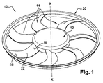
まず、本発明によるプロペラ10を示す図1を参照する。プロペラ10は、例えば、自動車のエンジン用ファン装置の一部を構成するものである。このプロペラは、有利には、例えば繊維又はガラス玉が充填されたポリアミド等の適当な樹脂材料を、一体成形して製造されるものである。プロペラ10は、「ボウル」とも呼ばれるハブ12を備えている。ハブ12は、所要の回転方向に軸XXの周りに回転駆動されるように、電気モータの駆動シャフト(図示せず)にキー止めしうるようになっている。
Reference is first made to FIG. 1 showing a
例えば7枚のブレードである複数のブレード14が、ハブ12から放射状に延びている。これらのブレードは、ハブ12に取り付けられた内側端部16(「ルート」又は[足部」としても知られている)と、外側端部18とを備えている。本実施形態では、外側端部18は、外側リング20(「ガイド」としても知られている)に接続されている。しかしながら、図示しない変形例として、ブレードの外側端部18を、自由端とすることもある。中間領域22は、端部16と18の間に延びている。
A plurality of
次に図2は、ブレード14の扁平化された横断図、すなわち、プロペラの軸XXの周りの回転の円柱表面によりブレードを横断し、この円柱表面を扁平化することにより得られる閉曲線を示している。ブレード14は、扁平化されたS字型の断面輪郭形状を有している。この断面輪郭は、曲線形の内側面24と、曲線形の外側面26により画成されている。これら2つの面は、前縁28と後縁30で接続されている。
FIG. 2 next shows a flattened cross-section of the
本実施形態における断面形状は、反曲点34を持つ中立軸32を有する特徴的な形状を有している。中立軸は、1次近似において、断面を形成する内側面24と外側面26の中間に位置する中央線と一致するものである。中立軸32は、反曲した曲率又は湾曲を有している。このため、中立軸32は、反対向きの2つの湾曲、すなわち、前縁28と反曲点34の間との凸状湾曲C1と、反曲点34と後縁30との間の凹状湾曲C2とを備えている。従って、中立軸32は、前縁28と後縁30を結ぶスパン36の両側から延びている。
The cross-sectional shape in the present embodiment has a characteristic shape having a
図2から分かるように、反曲点34は、前縁から測って、スパンの長さLの20〜80%の地点に位置している。図2に示すように、反曲点34が位置する領域Dは、矢高を有する区間の形状を有している。一般に、反曲点34は、図2のように、前縁28よりも後縁30の近くに位置していることが望ましい。
As can be seen from FIG. 2, the
反曲点のレベルにおいて、中立軸に対する接線Tは、スパン36と交差し、少なくとも4度の角度Aをなしている。この角度Aは、10〜20度であることが望ましい。この角度が、これより大きくなると、湾曲C1及び/又はC2が強くなり過ぎてしまう。
At the level of the inflection point, the tangent line T to the neutral axis intersects the
断面における凸状湾曲C1は、少なくとも2%の矢高を有している。ここで、矢高とは、スパン36に対する中立軸32の高さH1と、スパン36の長さLの比のことである(図3参照)。矢高は、例えば、4〜8%である。
The convex curve C 1 in the cross section has an arrow height of at least 2%. Here, the arrow height is the ratio of the height H 1 of the
同様に、断面における凹状湾曲C2は、少なくとも2%の矢高を有している。ここで、矢高とは、スパン36に対する中立軸32の高さH2と、スパンの長さLの比のことである(図4参照)。矢高は、例えば、4〜8%である。
Similarly, the concave curvature C 2 in cross section has an arrow height of at least 2%. Here, the arrow height is the ratio of the height H 2 of the
図示の実施形態では、H1はH2よりも大きく、そのため、凸状湾曲C1の矢高は、凹状湾曲C2の矢高よりも大きくなっている。 In the illustrated embodiment, H 1 is greater than H 2 , so the arrow height of the convex curve C 1 is greater than the arrow height of the concave curve C 2 .
図5は、図2に示したブレードの断面と類似する他のブレードの断面を示す。また、高さH1及びH2と角度Aが明示されている。 FIG. 5 shows a cross section of another blade similar to the cross section of the blade shown in FIG. Also, the heights H 1 and H 2 and the angle A are clearly shown.
図6は、本発明の第2の実施形態によるブレード14の扁平化された断面図であり、上述の第1の実施形態におけるブレードの断面と類似するブレードの断面を示している。この実施形態では、ブレード14の中立軸32は、その長さの少なくとも一部において、前縁28と中間点38の間の凸状湾曲C1と、中間点38と後縁30の間のほぼ平坦な部分Pとを有する断面とされている。
FIG. 6 is a flattened cross-sectional view of a
特徴的な形態では、中間点38の領域における中立軸に対する接線Tは、スパン36と交差し、少なくとも4度の角度Bをなしている。この角度Bは、中立軸に対する接線とスパンのなす角度が最大となる位置におけるものである。この角度Bは、望ましくは10〜20度であり、例えば8度及び12度である。
In a characteristic form, the tangent T to the neutral axis in the region of the
中間点38は、凸状湾曲C1と平坦部Pの接合点に位置する中立軸32の反曲点と実質的に一致している。
The
平坦部Pは、スパン36の長さLの10〜80%、特に20〜60%の長さを有している。この長さは、図6の実施例では、スパン36の長さLのほぼ3分の1である。従ってこの例では、中間点38は、前縁28よりも後縁30の近くにある。
The flat portion P has a length of 10 to 80% of the length L of the
本発明の第1及び第2の実施形態における断面輪郭は、ブレード14の全長にわたって、又はこの全長の一部にのみ設けることができる。この実施形態では、ブレード14は、ハブのレベルにあるブレードのルートの領域から始まって、ブレードの端部領域に至るまで続く断面形を有している。
The cross-sectional profile in the first and second embodiments of the present invention can be provided over the entire length of the
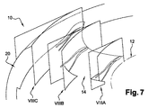
次に、本発明の第1の実施形態における進展する断面形の例を説明するために、図7と、図8A,図8B及び図8Cを参照する。図7は、プロペラの一部を示す図であり、ブレードの1つは、ハブに近いルートの領域と、中間領域と、リングに近い外側端部に近い領域において、それぞれ円筒断面VIIIA、VIIIB及びVIIICの3つの位置で切断されている。 Next, in order to describe an example of a developing cross-sectional shape in the first embodiment of the present invention, reference is made to FIG. 7 and FIGS. 8A, 8B, and 8C. FIG. 7 shows a portion of the propeller, where one of the blades has a cylindrical cross section VIIIA, VIIIB, and VIIIB, respectively, in the root region near the hub, the intermediate region, and the region near the outer end near the ring. It is cut at three positions of VIIIC.
図8A、図8B及び図8Cは、対応する横断面図である。これらは、内側端部領域16(ルート)から、中間領域22(図8B)を経て、外側端部領域18に至る断面の変化を示している。図から分かるように、断面は、ルート領域(図8A)において、外側領域(図8C)におけるよりも大きく湾曲しており、移行部(図8B)を備えている。
8A, 8B and 8C are corresponding cross-sectional views. These show changes in the cross section from the inner end region 16 (root) to the
(本実施形態では扁平化されたSの形状を有する)断面形状を、ブレードの長さの少なくとも一部に設けた他のブレード形状とすることも可能である。この断面形は、本発明の第1又は第2の実施形態における特定の形状から進んで、湾曲の反転を有さず、反曲点を有しない航空機の翼型の従来形状に近くなっている。 The cross-sectional shape (having a flattened S shape in the present embodiment) may be another blade shape provided on at least a part of the length of the blade. This cross-sectional shape proceeds from the specific shape in the first or second embodiment of the present invention, and is close to the conventional shape of an aircraft wing shape that has no inversion of curvature and has no inflection points. .
第1の実施形態においては、凸状湾曲は、凹状湾曲によって延長されているが、第2の実施形態においては、凸状湾曲は、ほぼ平坦な部分によって延長されている。どちらの場合においても、凸状湾曲は、後縁に至る延長部(凹状湾曲又は略平坦な部分)を備えており、プロペラによって動かされる流体の流れに影響を与えるものである。 In the first embodiment, the convex curve is extended by a concave curve, but in the second embodiment, the convex curve is extended by a substantially flat portion. In either case, the convex curvature is provided with an extension (concave curvature or a substantially flat portion) leading to the trailing edge, which affects the flow of fluid moved by the propeller.
次に、本発明によるプロペラの作用を、従来技術によるプロペラと比較して説明する。 Next, the operation of the propeller according to the present invention will be described in comparison with the propeller according to the prior art.
図9は、従来のプロペラにおける空気流線を示している。従来のプロペラは、ブレードが航空機の翼型の断面形を有しており、(上述したように)ソリディティ、すなわち充実比は小さい。 FIG. 9 shows air flow lines in a conventional propeller. In conventional propellers, the blade has an airfoil cross-sectional shape and has a low solidity, ie, a solidity ratio (as described above).
オイラーの理論が示すように、タービン機関において、圧力の増加は、ブレードのスパンに沿った流れの偏向に依存する。多数の空気力学的断面形が、この種の偏向を得るために用いられてきた。高い剛率、すなわち、互いに近くに配置されたブレードにより、より良い案内が得られる。 As Euler's theory shows, in a turbine engine, the pressure increase depends on the deflection of the flow along the blade span. A number of aerodynamic cross sections have been used to obtain this type of deflection. Higher stiffness, i.e. better guidance is obtained with the blades located close to each other.
一方、ソリディティ(充実比)が低いと、流れの案内は非効率的であり、図9に示すように、前縁側において流れの分離が発生する。この図から分かるように、空気の流れは分離され、下側面Iではうまく案内されるが(矢印F1)、上側面Eでは乱流を生じ易い(矢印F2)。 On the other hand, when the solidity (solidity ratio) is low, the flow guidance is inefficient, and flow separation occurs on the leading edge side as shown in FIG. As can be seen from this figure, the air flow is separated and guided well on the lower side I (arrow F 1 ), but turbulence is likely to occur on the upper side E (arrow F 2 ).
この乱流の発生を避けるための従来の解決策は、スパンを断面形状の長いものとするか、より多くのブレードを用いることによって、剛率を向上させることである。しかしこれは、ファンのトルクを増大させることになる。従って、この種の解決は、自動車のエンジン用ファンに用いられる直流モータにおける技術的制約に、必ずしも合致しないものである。 A conventional solution to avoid this turbulent flow is to increase the stiffness by making the span longer in cross-section or using more blades. However, this increases the fan torque. Therefore, this type of solution does not necessarily meet the technical constraints of DC motors used in automobile engine fans.
本発明によれば、上述のような断面を採用したことにより、この種の不都合を回避することができる。 According to the present invention, this kind of inconvenience can be avoided by adopting the cross section as described above.
図10は、本発明によって形作られた(本例では扁平化されたS字形を有している)断面輪郭形状により、空気流線F1が、図9の場合のような分離又は乱流を形成することなく、互いに一緒であり続けている様子を示す。これらの線は、ブレー14の間で案内され、絞られている。同様のことが、本発明の第2の実施形態によって形成された断面輪郭によっても得られる。
FIG. 10 shows the cross-sectional profile formed by the present invention (having a flattened S-shape in this example), so that the air stream line F 1 is separated or turbulent as in FIG. It shows how they continue to be together without forming. These lines are guided and squeezed between the
本発明において、剛率は、少なくとも0.5であると有利であり、ブレードのルートからブレードの端部に至るまで、約0.9から約0.5まで変化し得る。従来のブレードと比較すると、従来のブレードの剛率は、ルートにおける約0.7から、端部における0.3まで変化する。このように、高い剛率により、本発明の第1又は第2の実施形態による断面によれば、乱流の発生その他の攪乱を生じることなく、また大きなトルクを必要とすることなく、より良い効果が得られる。 In the present invention, the stiffness is advantageously at least 0.5 and can vary from about 0.9 to about 0.5 from the root of the blade to the end of the blade. Compared to a conventional blade, the stiffness of a conventional blade varies from about 0.7 at the root to 0.3 at the end. Thus, due to the high rigidity, according to the cross section according to the first or second embodiment of the present invention, it is better without generating turbulence and other disturbances, and without requiring a large torque. An effect is obtained.
本発明の優先的な利用分野は、自動車のエンジン用ファン装置である。 The field of preferential use of the present invention is a fan device for a motor vehicle engine.
10 プロペラ
12 ハブ
14 ブレード
16 内側端部
18 外側端部
20 外側リング
24 内側面
26 外側面
28 前縁
30 後縁
32 中立軸
34 反曲点
36 スパン
38 中間点
B 角度
C1 凸状湾曲
C2 凹状湾曲
E 上側面
H 中立軸の高さ
I 下側面
L スパンの長さ
P 平坦部
T 接線
10
Claims (13)
前記ブレード(14)は、その長さの少なくとも一部において、扁平化されたS字型形状に形成された断面輪郭を備え、これにより、前記中立軸(32)は、反曲点(34)を有することができ、かつ前記前縁(28)及び前記反曲点(34)の間の凸状湾曲(C1)と、前記反曲点(34)及び前記後縁(30)の間の凹状湾曲(C2)との2つの反対向きの湾曲を備えており、
前記ブレード(14)は、前記ハブ(12)の近傍領域における前記断面輪郭から、前記ブレード(14)の外側端部領域における航空機の翼型の断面輪郭であって、その中立軸が反曲点を有さない断面輪郭まで、延在方向において変化している断面輪郭を有していることを特徴とするファン用プロペラ。 A fan propeller comprising a hub (12) and a plurality of blades (14) extending radially outward from the hub (12), each of the blades (14) having a neutral shaft (32) and A fan propeller having a cross-sectional profile having a span (36) extending between a leading edge (28) and a trailing edge (30) of the blade (14),
The blade (14) has a cross-sectional profile formed in a flattened S-shape at least in part of its length, whereby the neutral shaft (32) has an inflection point (34). And a convex curve (C 1 ) between the leading edge (28) and the inflection point (34 ) and between the inflection point (34) and the trailing edge (30 ) . has a curvature of the two opposite the concave curvature (C 2),
The blade (14) is an aircraft airfoil cross-sectional contour in the outer end region of the blade (14) from the cross-sectional contour in the region near the hub (12), and its neutral axis is an inflection point. A fan propeller characterized by having a cross-sectional profile that changes in the extending direction up to a cross-sectional profile that does not have a cross section .
前記ブレード(14)は、その長さの少なくとも一部において、前記中立軸(32)が、前記前縁(28)及び前記中間点(38)の間の凸状湾曲(C1)と、前記中間点(38)及び前記後縁(30)の間の略平坦部(P)とを有するように形作られた断面輪郭を備えており、
前記中間点(38)は、前記中立軸(32)に対する接線(T)と前記スパン(36)がなす角度が最大となる点に位置しており、
前記ブレード(14)は、前記ハブ(12)の近傍領域における前記断面輪郭から、前記ブレード(14)の外側端部領域における航空機の翼型の断面輪郭であって、その中立軸が前記中間点(38)と実質的に一致している反曲点を有さない断面輪郭まで、延在方向において変化している断面輪郭を有していることを特徴とするファン用プロペラ。 A fan propeller comprising a hub (12) and a plurality of blades (14) extending radially outward from the hub (12), each of the blades (14) having a neutral shaft (32) and A fan propeller having a cross-sectional profile having a span (36) extending between a leading edge (28) and a trailing edge (30) of the blade (14),
The blade (14) has at least a part of its length, and the neutral axis (32) has a convex curve (C 1 ) between the leading edge (28) and the intermediate point (38 ), and A cross-sectional profile shaped to have a midpoint (38) and a generally flat portion (P) between said trailing edge (30 ) ;
The intermediate point (38) is located at a point where the angle formed by the tangent (T) to the neutral axis (32) and the span (36) is maximum,
The blade (14) is an aircraft airfoil cross-sectional contour in the outer end region of the blade (14) from the cross-sectional contour in the region near the hub (12), the neutral axis of which is the intermediate point (38) A fan propeller characterized by having a cross-sectional contour that changes in the extending direction up to a cross-sectional contour that does not have an inflection point substantially coincident with (38) .
Applications Claiming Priority (3)
| Application Number | Priority Date | Filing Date | Title |
|---|---|---|---|
| FR0905893 | 2009-12-07 | ||
| FR0905893A FR2953571B1 (en) | 2009-12-07 | 2009-12-07 | FAN PROPELLER, ESPECIALLY FOR A MOTOR VEHICLE |
| PCT/EP2010/067007 WO2011069762A2 (en) | 2009-12-07 | 2010-11-08 | Fan propeller, in particular for a motor vehicle |
Publications (2)
| Publication Number | Publication Date |
|---|---|
| JP2013513062A JP2013513062A (en) | 2013-04-18 |
| JP6022941B2 true JP6022941B2 (en) | 2016-11-09 |
Family
ID=42371499
Family Applications (1)
| Application Number | Title | Priority Date | Filing Date |
|---|---|---|---|
| JP2012542424A Expired - Fee Related JP6022941B2 (en) | 2009-12-07 | 2010-11-08 | Propellers for fans such as automobiles |
Country Status (8)
| Country | Link |
|---|---|
| US (1) | US9353764B2 (en) |
| EP (1) | EP2510243B1 (en) |
| JP (1) | JP6022941B2 (en) |
| CN (1) | CN102753835B (en) |
| FR (1) | FR2953571B1 (en) |
| IN (1) | IN2012DN05065A (en) |
| PL (1) | PL2510243T3 (en) |
| WO (1) | WO2011069762A2 (en) |
Cited By (1)
| Publication number | Priority date | Publication date | Assignee | Title |
|---|---|---|---|---|
| RU2750736C1 (en) * | 2020-07-09 | 2021-07-01 | Марлен Мелитонович Абрамешвили | Device for measurement of cutting forces during drilling |
Families Citing this family (20)
| Publication number | Priority date | Publication date | Assignee | Title |
|---|---|---|---|---|
| FR2980244B1 (en) * | 2011-09-19 | 2014-07-04 | Sabella | HYDROLIAN BLADE |
| CN103032376B (en) * | 2011-10-09 | 2015-12-09 | 珠海格力电器股份有限公司 | Axial-flow leaf |
| WO2013154102A1 (en) * | 2012-04-10 | 2013-10-17 | シャープ株式会社 | Propeller fan, fluid sending device, and mold for molding |
| CN103867489B (en) * | 2012-12-14 | 2017-06-16 | 中航商用航空发动机有限责任公司 | Compressor blade, compressor and aero-engine |
| JP6133748B2 (en) * | 2013-10-09 | 2017-05-24 | 三菱重工業株式会社 | Impeller and rotating machine having the same |
| TWD160896S (en) * | 2013-10-09 | 2014-06-01 | 訊凱國際股份有限公司 | Cooling fan (2) |
| TWD160897S (en) * | 2013-10-09 | 2014-06-01 | 訊凱國際股份有限公司 | Cooling fan (1) |
| BR102014017202B1 (en) * | 2014-07-11 | 2020-11-03 | Marchesan Implementos E Máquinas Agrícolas Tatú S.A | rotor of an exhaust fan set for agricultural machinery |
| USD765188S1 (en) * | 2015-04-20 | 2016-08-30 | Calogero A. LaRussa | Flying propeller |
| USD782639S1 (en) * | 2015-06-24 | 2017-03-28 | Mitsubishi Electric Corporation | Propeller fan |
| USD787037S1 (en) * | 2015-07-01 | 2017-05-16 | Dometic Sweden Ab | Fan |
| US10400783B1 (en) * | 2015-07-01 | 2019-09-03 | Dometic Sweden Ab | Compact fan for a recreational vehicle |
| EP3205885A1 (en) * | 2016-02-10 | 2017-08-16 | Siemens Aktiengesellschaft | Compressor rotor blade and method for profiling said blade |
| JP1555680S (en) * | 2016-03-01 | 2016-08-08 | ||
| CN106545521B (en) * | 2017-01-16 | 2019-01-25 | 江苏汇创机电科技股份有限公司 | A kind of brshless DC motor noise reduction impeller |
| US11644046B2 (en) * | 2018-01-05 | 2023-05-09 | Aurora Flight Sciences Corporation | Composite fan blades with integral attachment mechanism |
| EP3891066A4 (en) * | 2018-12-07 | 2022-08-10 | Joby Aero, Inc. | Rotary airfoil and design method therefor |
| US20210147091A1 (en) * | 2019-11-14 | 2021-05-20 | Delson Aeronautics Ltd. | Ultra-wide-chord propeller |
| JP6930644B1 (en) * | 2020-09-29 | 2021-09-01 | ダイキン工業株式会社 | Propeller fan |
| CN115009487A (en) * | 2022-07-14 | 2022-09-06 | 中国人民解放军海军工程大学 | Rotor blade S-shaped anti-cavitation section structure and application and design method thereof |
Family Cites Families (12)
| Publication number | Priority date | Publication date | Assignee | Title |
|---|---|---|---|---|
| US1506937A (en) * | 1923-03-09 | 1924-09-02 | Tom Moore | Blade |
| GB513863A (en) * | 1938-04-21 | 1939-10-24 | M W Woods Ltd | Improvements in and relating to axial-flow fans |
| US4197057A (en) * | 1975-12-17 | 1980-04-08 | Aisin Seiki Kabushiki Kaisha | Fan assembly |
| JPS5851435Y2 (en) * | 1975-12-17 | 1983-11-22 | アイシンセイキ カブシキガイシヤ | Engine Ray Kiyakuyo Ikomigata Silent Fan |
| JPH0285898U (en) * | 1988-12-21 | 1990-07-06 | ||
| US4915588A (en) * | 1989-06-08 | 1990-04-10 | Siemens-Bendix Automotive Electronics Limited | Axial flow ring fan with fall off |
| JP3337530B2 (en) * | 1993-09-10 | 2002-10-21 | 東芝キヤリア株式会社 | Axial fan blades |
| US6116856A (en) * | 1998-09-18 | 2000-09-12 | Patterson Technique, Inc. | Bi-directional fan having asymmetric, reversible blades |
| TW524928B (en) * | 2001-04-26 | 2003-03-21 | Daikin Ind Ltd | Blower and air conditioner with the same |
| US6866414B2 (en) * | 2001-05-22 | 2005-03-15 | Jv Northwest, Inc. | Sanitary mixing assembly for vessels and tanks |
| GB2400089B (en) * | 2003-04-04 | 2006-07-26 | Adrian Alexander Hubbard | High lift and high strength aerofoil section |
| JP4501575B2 (en) * | 2004-07-26 | 2010-07-14 | 三菱電機株式会社 | Axial blower |
-
2009
- 2009-12-07 FR FR0905893A patent/FR2953571B1/en not_active Expired - Fee Related
-
2010
- 2010-11-08 WO PCT/EP2010/067007 patent/WO2011069762A2/en active Application Filing
- 2010-11-08 EP EP10773918.7A patent/EP2510243B1/en active Active
- 2010-11-08 IN IN5065DEN2012 patent/IN2012DN05065A/en unknown
- 2010-11-08 PL PL10773918T patent/PL2510243T3/en unknown
- 2010-11-08 JP JP2012542424A patent/JP6022941B2/en not_active Expired - Fee Related
- 2010-11-08 CN CN201080063289.1A patent/CN102753835B/en active Active
- 2010-11-08 US US13/514,153 patent/US9353764B2/en active Active
Cited By (1)
| Publication number | Priority date | Publication date | Assignee | Title |
|---|---|---|---|---|
| RU2750736C1 (en) * | 2020-07-09 | 2021-07-01 | Марлен Мелитонович Абрамешвили | Device for measurement of cutting forces during drilling |
Also Published As
| Publication number | Publication date |
|---|---|
| EP2510243B1 (en) | 2019-07-31 |
| FR2953571B1 (en) | 2018-07-13 |
| IN2012DN05065A (en) | 2015-10-09 |
| CN102753835A (en) | 2012-10-24 |
| EP2510243A2 (en) | 2012-10-17 |
| WO2011069762A3 (en) | 2011-08-25 |
| CN102753835B (en) | 2017-12-12 |
| WO2011069762A2 (en) | 2011-06-16 |
| PL2510243T3 (en) | 2021-07-19 |
| JP2013513062A (en) | 2013-04-18 |
| US9353764B2 (en) | 2016-05-31 |
| FR2953571A1 (en) | 2011-06-10 |
| US20130028747A1 (en) | 2013-01-31 |
Similar Documents
| Publication | Publication Date | Title |
|---|---|---|
| JP6022941B2 (en) | Propellers for fans such as automobiles | |
| JP5880288B2 (en) | Blower | |
| JP6117698B2 (en) | Blower wheel with varying chord length | |
| CA2572925C (en) | Axial fan blade having a convex leading edge | |
| JP4388992B1 (en) | Propeller fan, fluid feeder and mold | |
| JP6121329B2 (en) | Blower wheel with variable pitch angle | |
| JP5929522B2 (en) | Axial blower | |
| JP6428833B2 (en) | Propeller fan | |
| KR20000047976A (en) | Axial flow fan | |
| JP6493682B2 (en) | Centrifugal fan | |
| KR20050093343A (en) | Axial flow fan | |
| EP2351935A1 (en) | Propeller fan, fluid feeder and mold | |
| WO2015092924A1 (en) | Axial flow fan | |
| JP5562566B2 (en) | Wing body for fluid machinery | |
| CN111577655B (en) | Blade and axial flow impeller using same | |
| WO2018123519A1 (en) | Propeller fan | |
| JP4910534B2 (en) | Blower impeller | |
| US20180051712A1 (en) | Aerodynamically and acoustically improved car fan | |
| JP4388993B1 (en) | Propeller fan, fluid feeder and mold | |
| KR100663965B1 (en) | Axial flow fan | |
| JP6544463B2 (en) | Propeller fan | |
| KR102035317B1 (en) | Axial flow fan | |
| JP5862541B2 (en) | Low noise blower | |
| JP4152158B2 (en) | Axial fan | |
| JP2016205399A (en) | Electric fan or propeller fan for circulator, electric fan or circulator, and molding die |
Legal Events
| Date | Code | Title | Description |
|---|---|---|---|
| A621 | Written request for application examination |
Free format text: JAPANESE INTERMEDIATE CODE: A621 Effective date: 20131108 |
|
| A977 | Report on retrieval |
Free format text: JAPANESE INTERMEDIATE CODE: A971007 Effective date: 20140918 |
|
| A131 | Notification of reasons for refusal |
Free format text: JAPANESE INTERMEDIATE CODE: A131 Effective date: 20140924 |
|
| A601 | Written request for extension of time |
Free format text: JAPANESE INTERMEDIATE CODE: A601 Effective date: 20141215 |
|
| A602 | Written permission of extension of time |
Free format text: JAPANESE INTERMEDIATE CODE: A602 Effective date: 20141222 |
|
| A601 | Written request for extension of time |
Free format text: JAPANESE INTERMEDIATE CODE: A601 Effective date: 20150122 |
|
| A601 | Written request for extension of time |
Free format text: JAPANESE INTERMEDIATE CODE: A601 Effective date: 20150223 |
|
| A521 | Request for written amendment filed |
Free format text: JAPANESE INTERMEDIATE CODE: A523 Effective date: 20150323 |
|
| A131 | Notification of reasons for refusal |
Free format text: JAPANESE INTERMEDIATE CODE: A131 Effective date: 20150929 |
|
| A601 | Written request for extension of time |
Free format text: JAPANESE INTERMEDIATE CODE: A601 Effective date: 20151225 |
|
| A601 | Written request for extension of time |
Free format text: JAPANESE INTERMEDIATE CODE: A601 Effective date: 20160113 |
|
| A601 | Written request for extension of time |
Free format text: JAPANESE INTERMEDIATE CODE: A601 Effective date: 20160212 |
|
| A521 | Request for written amendment filed |
Free format text: JAPANESE INTERMEDIATE CODE: A523 Effective date: 20160329 |
|
| TRDD | Decision of grant or rejection written | ||
| A01 | Written decision to grant a patent or to grant a registration (utility model) |
Free format text: JAPANESE INTERMEDIATE CODE: A01 Effective date: 20160906 |
|
| A61 | First payment of annual fees (during grant procedure) |
Free format text: JAPANESE INTERMEDIATE CODE: A61 Effective date: 20161006 |
|
| R150 | Certificate of patent or registration of utility model |
Ref document number: 6022941 Country of ref document: JP Free format text: JAPANESE INTERMEDIATE CODE: R150 |
|
| R250 | Receipt of annual fees |
Free format text: JAPANESE INTERMEDIATE CODE: R250 |
|
| R250 | Receipt of annual fees |
Free format text: JAPANESE INTERMEDIATE CODE: R250 |
|
| LAPS | Cancellation because of no payment of annual fees |