JP6019246B2 - Engine start control device - Google Patents
Engine start control device Download PDFInfo
- Publication number
- JP6019246B2 JP6019246B2 JP2015540517A JP2015540517A JP6019246B2 JP 6019246 B2 JP6019246 B2 JP 6019246B2 JP 2015540517 A JP2015540517 A JP 2015540517A JP 2015540517 A JP2015540517 A JP 2015540517A JP 6019246 B2 JP6019246 B2 JP 6019246B2
- Authority
- JP
- Japan
- Prior art keywords
- engine
- piston
- dead center
- rotation
- top dead
- Prior art date
- Legal status (The legal status is an assumption and is not a legal conclusion. Google has not performed a legal analysis and makes no representation as to the accuracy of the status listed.)
- Active
Links
- 238000007906 compression Methods 0.000 claims description 50
- 230000006835 compression Effects 0.000 claims description 49
- 238000001514 detection method Methods 0.000 claims description 14
- 239000007858 starting material Substances 0.000 claims description 9
- 238000004364 calculation method Methods 0.000 description 26
- 230000002093 peripheral effect Effects 0.000 description 12
- 238000000034 method Methods 0.000 description 11
- 230000008569 process Effects 0.000 description 10
- 239000000446 fuel Substances 0.000 description 9
- 230000001133 acceleration Effects 0.000 description 7
- 230000033001 locomotion Effects 0.000 description 7
- 238000012545 processing Methods 0.000 description 6
- 230000007423 decrease Effects 0.000 description 5
- 238000010586 diagram Methods 0.000 description 5
- 230000005540 biological transmission Effects 0.000 description 4
- 238000007493 shaping process Methods 0.000 description 4
- 238000002485 combustion reaction Methods 0.000 description 3
- 230000004907 flux Effects 0.000 description 3
- 239000000203 mixture Substances 0.000 description 3
- 230000008859 change Effects 0.000 description 2
- 238000007796 conventional method Methods 0.000 description 2
- 230000000694 effects Effects 0.000 description 2
- 238000004880 explosion Methods 0.000 description 2
- 238000002347 injection Methods 0.000 description 2
- 239000007924 injection Substances 0.000 description 2
- 230000007246 mechanism Effects 0.000 description 2
- 230000004044 response Effects 0.000 description 2
- 230000000630 rising effect Effects 0.000 description 2
- XEEYBQQBJWHFJM-UHFFFAOYSA-N Iron Chemical group [Fe] XEEYBQQBJWHFJM-UHFFFAOYSA-N 0.000 description 1
- 229910000831 Steel Inorganic materials 0.000 description 1
- 238000013459 approach Methods 0.000 description 1
- 238000007599 discharging Methods 0.000 description 1
- 230000005669 field effect Effects 0.000 description 1
- 238000009434 installation Methods 0.000 description 1
- 238000010030 laminating Methods 0.000 description 1
- 238000012986 modification Methods 0.000 description 1
- 230000004048 modification Effects 0.000 description 1
- 239000010959 steel Substances 0.000 description 1
Images


Classifications
-
- F—MECHANICAL ENGINEERING; LIGHTING; HEATING; WEAPONS; BLASTING
- F02—COMBUSTION ENGINES; HOT-GAS OR COMBUSTION-PRODUCT ENGINE PLANTS
- F02N—STARTING OF COMBUSTION ENGINES; STARTING AIDS FOR SUCH ENGINES, NOT OTHERWISE PROVIDED FOR
- F02N19/00—Starting aids for combustion engines, not otherwise provided for
- F02N19/005—Aiding engine start by starting from a predetermined position, e.g. pre-positioning or reverse rotation
-
- F—MECHANICAL ENGINEERING; LIGHTING; HEATING; WEAPONS; BLASTING
- F02—COMBUSTION ENGINES; HOT-GAS OR COMBUSTION-PRODUCT ENGINE PLANTS
- F02D—CONTROLLING COMBUSTION ENGINES
- F02D41/00—Electrical control of supply of combustible mixture or its constituents
- F02D41/009—Electrical control of supply of combustible mixture or its constituents using means for generating position or synchronisation signals
-
- F—MECHANICAL ENGINEERING; LIGHTING; HEATING; WEAPONS; BLASTING
- F02—COMBUSTION ENGINES; HOT-GAS OR COMBUSTION-PRODUCT ENGINE PLANTS
- F02N—STARTING OF COMBUSTION ENGINES; STARTING AIDS FOR SUCH ENGINES, NOT OTHERWISE PROVIDED FOR
- F02N11/00—Starting of engines by means of electric motors
- F02N11/04—Starting of engines by means of electric motors the motors being associated with current generators
-
- F—MECHANICAL ENGINEERING; LIGHTING; HEATING; WEAPONS; BLASTING
- F02—COMBUSTION ENGINES; HOT-GAS OR COMBUSTION-PRODUCT ENGINE PLANTS
- F02D—CONTROLLING COMBUSTION ENGINES
- F02D41/00—Electrical control of supply of combustible mixture or its constituents
- F02D41/009—Electrical control of supply of combustible mixture or its constituents using means for generating position or synchronisation signals
- F02D2041/0095—Synchronisation of the cylinders during engine shutdown
-
- F—MECHANICAL ENGINEERING; LIGHTING; HEATING; WEAPONS; BLASTING
- F02—COMBUSTION ENGINES; HOT-GAS OR COMBUSTION-PRODUCT ENGINE PLANTS
- F02D—CONTROLLING COMBUSTION ENGINES
- F02D41/00—Electrical control of supply of combustible mixture or its constituents
- F02D41/02—Circuit arrangements for generating control signals
- F02D41/04—Introducing corrections for particular operating conditions
- F02D41/042—Introducing corrections for particular operating conditions for stopping the engine
-
- F—MECHANICAL ENGINEERING; LIGHTING; HEATING; WEAPONS; BLASTING
- F02—COMBUSTION ENGINES; HOT-GAS OR COMBUSTION-PRODUCT ENGINE PLANTS
- F02N—STARTING OF COMBUSTION ENGINES; STARTING AIDS FOR SUCH ENGINES, NOT OTHERWISE PROVIDED FOR
- F02N11/00—Starting of engines by means of electric motors
- F02N11/08—Circuits or control means specially adapted for starting of engines
-
- F—MECHANICAL ENGINEERING; LIGHTING; HEATING; WEAPONS; BLASTING
- F02—COMBUSTION ENGINES; HOT-GAS OR COMBUSTION-PRODUCT ENGINE PLANTS
- F02N—STARTING OF COMBUSTION ENGINES; STARTING AIDS FOR SUCH ENGINES, NOT OTHERWISE PROVIDED FOR
- F02N19/00—Starting aids for combustion engines, not otherwise provided for
- F02N19/005—Aiding engine start by starting from a predetermined position, e.g. pre-positioning or reverse rotation
- F02N2019/008—Aiding engine start by starting from a predetermined position, e.g. pre-positioning or reverse rotation the engine being stopped in a particular position
Landscapes
- Engineering & Computer Science (AREA)
- Chemical & Material Sciences (AREA)
- Combustion & Propulsion (AREA)
- Mechanical Engineering (AREA)
- General Engineering & Computer Science (AREA)
- Control Of Vehicle Engines Or Engines For Specific Uses (AREA)
- Combined Controls Of Internal Combustion Engines (AREA)
Description
本発明は、エンジン始動制御装置に関する。
本願は、2013年10月1日に、日本に出願された特願2013−206376号に基づき優先権を主張し、その内容をここに援用する。The present invention relates to an engine start control device.
This application claims priority on October 1, 2013 based on Japanese Patent Application No. 2013-206376 for which it applied to Japan, and uses the content here.
近年、余分な燃料消費を抑え、排出ガスを低減するために、信号待ちや渋滞等での停車時にエンジンを自動的に停止しスロットル操作に応じてエンジンを再始動するアイドルストップ制御を行う車両が増えている。
しかし、エンジンの再始動時において、ACG(AC Generator)スタータのモータトルク単体では、トルクが不足する場合がある。このため、特許文献1には、アイドルストップ制御時において、エンジン停止直後にクランクシャフトを圧縮上死点後の所定位置まで逆転駆動してからクランキングすることにより慣性エネルギーを蓄えるようにしたエンジン始動制御装置が開示されている。In recent years, in order to suppress excessive fuel consumption and reduce exhaust gas, vehicles that perform idle stop control that automatically stops the engine when the vehicle stops due to traffic light or traffic jams and restarts the engine according to the throttle operation. is increasing.
However, when the engine is restarted, the torque of the motor torque alone of the ACG (AC Generator) starter may be insufficient. For this reason, Patent Document 1 discloses an engine start in which inertia energy is stored by cranking the crankshaft to a predetermined position after compression top dead center immediately after the engine is stopped during idle stop control. A control device is disclosed.
図8に特許文献1のような一般的な始動制御の動作を示す。図8に示すように、ECU(Engine Control Unit)がエンジン停止信号を検知すると、点火プラグの点火停止とインジェクターによる燃料噴射の停止を行う。 FIG. 8 shows a general start control operation as in Patent Document 1. As shown in FIG. 8, when an ECU (Engine Control Unit) detects an engine stop signal, ignition of the spark plug is stopped and fuel injection by the injector is stopped.
上記停止動作後、ロータは慣性回転を行うため、クランクシャフトも同様に慣性回転を始める。クランクシャフトが慣性回転を始めてから停止するまでの間、ピストンは図8の圧縮上死点を幾度か越えて停止する。例えばピストンは図8に示す圧縮上死点Bは越えることができずに、圧縮上死点Bの手前のクランク角310°の位置で反転し、最終的に図8に示すようにクランク角690°(排気行程)の位置で停止する。 Since the rotor performs inertia rotation after the stop operation, the crankshaft similarly starts inertia rotation. The piston stops several times above the compression top dead center of FIG. 8 until the crankshaft starts inertial rotation and stops. For example, the piston cannot exceed the compression top dead center B shown in FIG. 8 and reverses at a crank angle of 310 ° before the compression top dead center B, and finally the crank angle 690 as shown in FIG. Stop at the ° (exhaust stroke) position.
車両の始動の伴い、エンジンを始動させるには、ピストンが圧縮上死点Bを越える必要がある。ただし、ピストンが圧縮上死点Bを越えるには、ロータに対して多くのトルクエネルギーを要する。そのため、上述したように、ECUはピストンが所定の位置に到達するまでロータを逆転駆動させ、圧縮上死点Bまでの助走期間を長くすることで、勢いをつけて圧縮上死点Bを乗り越えるようにしている。所定の位置は例えば膨張過程内であり、図8では470°として示す。 In order to start the engine with the start of the vehicle, the piston needs to exceed the compression top dead center B. However, in order for the piston to exceed the compression top dead center B, a lot of torque energy is required for the rotor. Therefore, as described above, the ECU drives the rotor in the reverse direction until the piston reaches a predetermined position, and lengthens the run-up period to the compression top dead center B, thereby gaining momentum and overcoming the compression top dead center B. I am doing so. The predetermined position is, for example, in the expansion process, and is shown as 470 ° in FIG.
ECUはピストンが所定の位置で停止したと判定すると、始動状態に切り替わる。始動状態とは、ロータが正転駆動するためのトリガーを認識できる状態のことである。正転駆動するためのトリガーとは、例えばスロットルスイッチである。 When the ECU determines that the piston has stopped at a predetermined position, the ECU switches to a starting state. The start state is a state in which the trigger for the forward rotation of the rotor can be recognized. The trigger for forward driving is, for example, a throttle switch.
ECUに正転駆動するためのトリガーが入力されると、ECUは点火プラグの点火開始とインジェクターによる燃料噴射を行うととともに、ACGスタータに正転駆動信号を入力する。ACGスタータは正転駆動を行い、圧縮上死点Bを乗り越え、車両は始動する。 When a trigger for forward rotation driving is input to the ECU, the ECU starts ignition of the spark plug and injects fuel by the injector, and inputs a forward driving signal to the ACG starter. The ACG starter performs forward rotation, gets over the compression top dead center B, and the vehicle starts.
しかしながら、特許文献1のエンジン始動制御装置をミッション付の自動二輪車に搭載する場合、ロータが逆転駆動すると、エンジンが逆回転しミッション付の自動二輪車は後進する場合がある。なぜならば、特許文献1のエンジン始動制御装置は、ミッション付の自動二輪車の場合、クランクシャフトとACGスタータのロータが直結しているからである。よって上述したエンジン始動制御装置はスクータのような、ベルト変速車には採用できるが、ミッション付の自動二輪車には搭載できない。 However, when the engine start control device of Patent Document 1 is mounted on a motorcycle with a mission, when the rotor is driven in reverse, the engine rotates reversely and the motorcycle with a mission may move backward. This is because, in the engine start control device of Patent Document 1, in the case of a motorcycle with a transmission, the crankshaft and the rotor of the ACG starter are directly connected. Therefore, the engine start control device described above can be used in a belt-type transmission such as a scooter, but cannot be installed in a motorcycle with a transmission.
本発明は、アイドルストップ制御後の始動において、逆転駆動を行うことなく、エンジンの再始動ができ、車両を後進させることを阻止するエンジン始動制御装置を提供する。 The present invention provides an engine start control device capable of restarting an engine and preventing the vehicle from moving backward without performing reverse rotation driving at the start after the idle stop control.
本発明の第1の態様によれば、エンジンの始動時にスタータモータとして機能し、当該エンジンの始動後においては発電機として機能する、前記エンジンのクランクシャフトに連結されたロータを有する回転電機において、前記回転電機の慣性回転を制御するエンジン始動制御装置であって、スロットル弁が全閉状態になった後にエンジンの停止作業を実行し、前記回転電機を慣性回転させる第1の制御工程と、前記回転電機が慣性回転している際に、ピストンの現在位置が圧縮上死点か否かを判断する第2の制御工程と、前記第2の制御工程で、の現在位置が圧縮上死点であると判断された場合に、前記ピストンが次の圧縮上死点を越えられるか否かを判断し、前記ピストンが次の圧縮上死点を越えられないと判断した場合に、前記ピストンが所定の停止領域内で停止するように、前記回転電機の慣性回転を制御する第3の制御工程と、を有する。 According to the first aspect of the present invention, in the rotating electrical machine having a rotor connected to the crankshaft of the engine that functions as a starter motor when the engine is started and functions as a generator after the engine is started, wherein an engine start control device for controlling the inertial rotation of the rotary electric machine, a first control step of throttle valve performs the shutdown operations of the engine after the fully closed state to the inertial rotation of the rotary electric machine, wherein When the rotary electric machine is rotating inertially, the second control step for determining whether or not the current position of the piston is the compression top dead center , and the current position in the second control step is the compression top dead center. If it is determined that, when the piston is determined whether topped the following compression top dead center, the piston is determined to not exceed the following compression top dead center, the piston So it stops at the predetermined stop region has a third control step of controlling the inertial rotation of the rotary electric machine.
本発明の第2の態様によれば、上記したエンジン始動制御装置において、前記所定の停止領域内とは、前記ピストンが前記圧縮上死点を越えて、前記エンジンが始動できる位置であってもよい。 According to a second aspect of the present invention, the engine start control device described above, wherein the predetermined stopping area, the piston beyond the compression top dead center, even the position where the engine can be started Good.
本発明の第3の態様によれば、エンジン始動制御装置は、前記回転電機の回転する角度を検知する回転検出センサを更に備える。前記第3の制御工程において、前記回転検出センサからの前記エンジンの回転を示す回転情報から算出した慣性回転する前記回転電機のクランクシャフトの角速度に基づいて、前記ピストンを次の圧縮上死点を越えられるか否か判断する。 According to the third aspect of the present invention, the engine start control device further includes a rotation detection sensor that detects an angle of rotation of the rotating electrical machine. In the third control step, based on the angular velocity of the crankshaft of the rotating electric machine that rotates inertially calculated from the rotation information indicating the rotation of the engine from the rotation detection sensor, the piston is subjected to the next compression top dead center. Judge whether it can be exceeded .
本発明の第4の態様によれば、エンジン始動制御装置は、前記第3の制御工程において、前記回転電機に逆転トルクを発生させることで、前記ピストンを前記所定の停止領域内で停止させる。 According to the fourth aspect of the present invention, in the third control step, the engine start control device causes the rotating electrical machine to generate reverse torque, thereby stopping the piston within the predetermined stop region.
上記したエンジン始動制御装置によれば、ロータの慣性回転時において、スロットル弁を全閉にすることによる第1の制動力と、回転電機に通電を行い慣性回転とは逆向きにトルクが働くようにする第2の制動力により、慣性回転を所定の位置、つまり、圧縮上死点を乗り越えるのに十分な助走期間を確保できる位置に停止させることができる。このようにすると、エンジンの逆転駆動動作が無い為、ミッション付のバイクでも、逆転時の後進の問題が解消される。 According to the engine start control device described above, during the inertia rotation of the rotor, the first braking force by fully closing the throttle valve and the rotating electrical machine are energized so that the torque works in the direction opposite to the inertia rotation. By the second braking force, the inertial rotation can be stopped at a predetermined position, that is, a position where a sufficient run-up period can be secured to overcome the compression top dead center. In this way, since there is no reverse rotation drive operation of the engine, the problem of reverse rotation at the time of reverse rotation is solved even with a motorcycle with a mission.
以下、図面を参照して、本発明の一実施形態について、図面を参照しながら説明する。
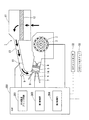
図1は、本発明の一実施形態による回転電機の制御系ブロック図である。図1に示すように、典型的にはガソリン等を燃料とする内燃機関であるエンジン1は、図示を省略する車両に搭載される。
本発明の一実施形態の説明においては、本発明のエンジン始動制御装置がミッション付モータの自動二輪車に搭載されていることを前提とする。Hereinafter, an embodiment of the present invention will be described with reference to the drawings.
FIG. 1 is a block diagram of a control system for a rotating electrical machine according to an embodiment of the present invention. As shown in FIG. 1, an engine 1 that is typically an internal combustion engine using gasoline or the like as a fuel is mounted on a vehicle not shown.
In the description of one embodiment of the present invention, it is assumed that the engine start control device of the present invention is mounted on a motorcycle with a motor with a transmission.
エンジン1は回転電機2、回転検出センサ3、ピストン4、シリンダー5、点火プラグ6、排気弁7、吸気弁8、インジェクター9、スロットル弁10、エアクリーナ11、及び、吸気通路13から構成されている。
The engine 1 includes a rotating
ECU200は、回転電機2のジェネレータ機能が発生する三相交流を全波整流する全波整流ブリッジ回路201、第1制御部203、第2制御部204を備えている。
The ECU 200 includes a full-wave
また、ECU200には、回転検出センサ3 、スロットルセンサ32、スロットルスイッチ33などの各部センサから検出信号が入力される。それらのセンサの結果に基づいて、回転電機2、点火プラグ6、インジェクター9、スロットル弁10の制御を行う。
Further, the
エアクリーナ11は矢印に示す吸気経路を通り、外気の吸気を行う。また、エアクリーナ11は吸気した外気をエアフィルタ12により浄化して、吸気通路13に供給する。
The
吸気通路13の内部には、スロットル弁10が配置されている。スロットル弁10は、吸気される空気量を制御する弁である。スロットル弁10の開閉に関しては、例えば、自動二輪車のスロットルグリップの回動操作に応じて、ECU200がスロットル弁10の開閉を制御する。その開閉量(スロットル開度)がスロットルセンサ32により検知される。
または、スロットルグリップとスロットル弁がワイヤで接続されているシステムにおいては、スロットルグリップの回動操作に連動してスロットル弁が開閉する。A
Alternatively, in a system in which the throttle grip and the throttle valve are connected by a wire, the throttle valve opens and closes in conjunction with the turning operation of the throttle grip.
スロットル弁10の開度に応じて吸入された外気は、インジェクター9から噴射された燃料と混合される。この混合された燃料混合気体は吸気弁8を介してエンジン1のシリンダー5に供給される。ここで燃料は図示しないポンプで加圧され、インジェクター9に供給される。
The outside air sucked according to the opening degree of the
ピストン4は、シリンダー5の内部に設けられ、中空円筒状に形成されたシリンダー5の内周面に沿って往復を行う。ピストン4の上面と下部は、コネクティングロッド(図示しない)を介して、クランクシャフトに接続される。これにより、ピストン4の往復動作がクランクシャフトの回転運動に変換される。よって、クランク角を求めることで、ピストン4の位置を求めることができる。
The
シリンダー5の頂面14には、吸入空気をシリンダー5内に供給するための吸気弁8とシリンダー5内で燃焼した後の排気ガスを排出するための排気弁7が設けられている。これらの排気弁7、吸気弁8は、不図示のカムシャフトによって各々の動作を個別に制御される。また、シリンダー5の頂部には、点火プラグ6がその先端をシリンダー5側に突出させた状態で設けられる。点火プラグ6はECU200の命令指示により、火花(スパーク)を発生させ、ピストン4内の燃料と空気を混ぜた混合気に点火する。
The
排気弁7は、排気ガスを外へ放出する処理だけに使用されるわけではない。始動時において、シリンダー5の中の混合気体を圧縮する際に、必要に応じて排気弁7を少し開けて、ピストン4の移動に必要な力を減らすことも行う。
The
図2に本発明の一実施形態による回転電機2を示す。回転電機2は、エンジン1の始動時においてはスタータモータとして機能し、エンジン1の始動後においては発電機として機能するアウターロータ型のものである。
FIG. 2 shows a rotating
回転電機2は、不図示のエンジン1のクランクシャフトに固定されているロータ21と、ロータ21の回転角を検出する回転検出センサ3と、電磁鋼板を積層して構成されるステータ鉄心26とステータ鉄心26に巻回される複数のコイル25とを備え、不図示のエンジンブロックに固定されるステータ22と、ロータ21の内周面に固定されているマグネット24から構成されている。
The rotating
クランクシャフトはボス部(不図示)に固定されることでロータ21はクランクシャフトと直結し、一体回転を行う。図3は、ロータ21の内周側を展開して示した図である。
同図にも示すように、ロータ21の内周面には、複数のマグネット24が円周方向に沿って等間隔に取り付け、固定されている。そして、一つのマグネット24cは内側面がN極に着磁された主磁極部242の長尺方向、上端あるいは下端のいずれかに、内側面がS極に着磁された短尺な副磁極部240が形成されている。Since the crankshaft is fixed to a boss portion (not shown), the
As shown in the figure, a plurality of
ここで、図中、内側面全域がN極に着磁されているマグネット24をマグネット24a、内側面全域がS極に着磁されているマグネット24をマグネット24b、主磁極部242と副磁極部240を備えたマグネット24をマグネット24cと呼ぶ。このロータ21では、隣接する特定の一組のマグネット24a、24aの間にマグネット24cが配置され、他の隣接するマグネット24a、24a間にマグネット24bが配置されている。
Here, in the figure, the
図中において、主磁極部242は、ロータ21の内周面の軸方向の中央側に対峙する位置M2に配置され、主に、コイル25の転流タイミングを検出するための基準点を検出するターゲットとして用いられる。
副磁極部240は、ロータ21の軸方向の一端側の位置M1に配置され、エンジンの点火タイミングを検出するためのターゲットとして用いられる。そして、本実施形態においては、マグネット24a、マグネット24c、マグネット24aと連続して並んで配置されている。したがって、ロータ21の内周面の軸方向の中央側に対峙する位置M2においては、マグネット24は、N極とS極が交互に現れることになるが、ロータ21の軸方向の一端側の位置M1においては、マグネット24cの前後(円周方向の前後)のみマグネット3個分だけN極が連続して現れる。
したがって、ロータ21の内周側は、ロータ21の軸方向の一端側の位置M1の一部(マグネット24a、マグネット24c、マグネット24aが連続して配置されている箇所)以外ではN極とS極が交互に現れる。In the figure, the main
The sub
Therefore, the inner peripheral side of the
回転検出センサ3には図3に示す第1ホールIC(センサ素子)3a、第2ホールIC(センサ素子)3b、第3ホールIC(センサ素子)3c、第4ホールIC(センサ素子)3dがそれぞれ収容配置される。回転検出センサ3はステータ22に固定されている。これらのホールIC3a、3b、3c、3dは、ロータ21の内周面に対向してマグネット24の磁束の切り替わりを検出する。
The
第1ホールIC3aと第2ホールIC3b、第3ホールIC3c、第4ホールIC3dの各々は、それぞれ磁石の長尺方向における設置高さが異なる。図3に示すように、第1ホールIC3aは、ロータ21の内周面の軸方向の一端側に対峙する位置M1に配置されている。
一方、第2ホールIC3b、第3ホールIC3c、第4ホールIC3dの各々は、第1ホールIC3aと異なり、ロータ21の内周面の軸方向の中央側に対峙する位置M2に配置されている。これにより、第1ホールIC3aは、マグネット24cの副磁極部240を通る高さでマグネット24aと24bの磁束の切り替わりのみを検出する。また、第2ホールIC3b、第3ホールIC3c、第4ホールIC3dは、マグネット24cの主磁極部242を通る高さでマグネット24a、24b、24cの磁束の切り替わりを検出する。なお、図3に示すマグネット24a、マグネット24b、主磁極部242、副磁極部240は、それぞれの磁極を反転させてもよい。すなわち、N極ならS極に、S極ならN極に磁極を替えても良い。Each of the
On the other hand, unlike the
第2ホールIC3b、第3ホールIC3c、第4ホールIC3dは、ロータ21の中央側の位置M2で検出した信号を、ロータ21の回転位置信号としてエンジン始動制御装置に出力する。第1ホールIC3aは、ロータ21の軸方向の一端側の位置M1で検出した信号を、ロータ21の円周上の絶対位置情報信号としてECU200に出力する。ECU200では、第2、第3、第4ホールIC3b、3c、3dの出力信号を受けて、3相のコイル25に対する転流タイミングを制御するとともに、第1ホールIC3aの出力信号と第2ホールIC3b、第3ホールIC3c、第4ホールIC3dの出力信号を受けて、常時、ロータの回転数(回転速度)とピストン4の位置を算出している。
なお、回転検出センサ3は、ACGスタータのセンサである場合について示したが、ロータの回転を検出できればよいのであってこれに限られない。すなわち、ロータの外周面に形成されたトリガーピースを検出するセンサであっても良い。その場合は、ECU200は、センサが検出したトリガーピースの回転情報を基に、常時、ロータ21の回転数(回転速度)とピストン4の位置を算出する。The
In addition, although the
次にECU200について説明する。
図4は回転電機2の駆動制御に係るECU200内の主要部の構成を示したブロック図である。
第2制御部204はセンサ信号処理部210、ロータ状態演算部211、進角演算部212を有している。
3相全波整流ブリッジ回路は、直列接続されたFET(Field Effect Transistor)を並列接続して構成される。Next, the
FIG. 4 is a block diagram showing a configuration of a main part in the
The
The three-phase full-wave rectification bridge circuit is configured by connecting FETs (Field Effect Transistors) connected in series in parallel.
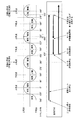
センサ信号処理部210は、回転検出センサ3からの信号を図5に示すような矩形波に波形整形を行う。なお、同図中のパルス信号P2、P3、P4の各々は、等分に設置された第2ホールIC3b、第3ホールIC3c、第4ホールIC3dの出力を波形整形して得られるパルス信号をそれぞれ示している。パルス信号P1は、第1ホールIC3aの出力を波形整形して得られるパルス信号を示している。センサ信号処理部210は、波形整形して得られるパルス信号P1〜P4をロータ状態演算部211に出力する。
The sensor
ロータ状態演算部211は、角速度と角加速度とピストン4の現在位置とを算出する。
まず、角速度と角加速度の算出方法について述べる。
ロータ状態演算部211は、ロータが1回転するために必要な時間を算出することで角速度を算出する。ロータが1回転するために必要な時間は、パルス信号P2、P3、P4の間の時間を計測することによって、算出することができる。
例えば、信号P2の立ち上がりをT1とし、その後立ち上がる信号P4の立下りをT2とする。T1からT2の間の角度を10度と設定することで、T1とT2の間の時間からT2時の角速度ω2を以下に示す式(1)で計算することができる。
ω2=10/(T2−T1) ・・・(1)The rotor
First, the calculation method of angular velocity and angular acceleration will be described.
The rotor
For example, the rising edge of the signal P2 is T1, and the falling edge of the signal P4 that rises thereafter is T2. By setting the angle between T1 and T2 to 10 degrees, the angular velocity ω2 at T2 can be calculated from the time between T1 and T2 by the following equation (1).
ω2 = 10 / (T2-T1) (1)
さらに、その後立ち上がる信号P3の立ち上がりをT3とする。T2からT3の間の角度を10度と設定することで、T2とT3の間の時間からT3時の角速度ω3を以下に示す式(2)で計算することができる。
ω3=10/(T3−T2) ・・・(2)Further, the rising edge of the signal P3 that rises thereafter is defined as T3. By setting the angle between T2 and T3 as 10 degrees, the angular velocity ω3 at T3 can be calculated from the time between T2 and T3 by the following equation (2).
ω3 = 10 / (T3-T2) (2)
ロータ状態演算部211は、算出したω2とω3から、T3時の角加速度a3を以下に示す式(3)で計算することができる。
a3=(ω3−ω2)/(T3−T2) ・・・(3)The rotor
a3 = (ω3-ω2) / (T3-T2) (3)
次に、ピストン4の現在位置の算出方法について述べる。
ピストン4の現在位置は、上死点位置を0とし、ピストンストロークをXとし、上死点から現在のピストン4の位置をxとし、さらに、上死点タイミングをT4とし、T4からセンサ信号P2からP4の矩形波のエッジの数yをカウントし、以下に示す式(4)で計算することができる。
x=X/2×(1−cos(y×10)) ・・・(4)
ピストンストロークXは、ピストン4の上死点から下死点までの運動距離である。上死点タイミングT4は、第1ホールIC3aの出力(パルス信号P1)がハイ状態のまま第4ホールIC3dの出力(パルス信号P4)がハイからローに切り替わるタイミングである。このタイミングT4は上死点であることを示す絶対位置信号である。Next, a method for calculating the current position of the
As for the current position of the
x = X / 2 × (1-cos (y × 10)) (4)
The piston stroke X is a movement distance from the top dead center to the bottom dead center of the
一方、4サイクルエンジンの場合、燃焼行程1サイクルにクランクシャフトが2回転する為、同じピストン4の位置でも、2通りの状態が存在する。すなわち、上死点として、圧縮上死点及び排気上死点がある。このため、上死点でも、圧縮上死点か、排気上死点か、ピストン4の位置だけでは判別できない。そこで、ロータ状態演算部211は、上死点時の角加速度が定められた角加速度より小さければ、圧縮上死点とみなす。
On the other hand, in the case of a four-cycle engine, since the crankshaft rotates twice in one cycle of the combustion stroke, there are two states even at the
ロータ状態演算部211は、ピストン4の現在位置、クランクの角速度、角加速度、エンジン工程を求めた後、これらの状態において、ピストン4が圧縮上死点を越えられるか否かを判定する。
After obtaining the current position of the
ピストン4の位置が圧縮上死点だと判別されると、上死点時のクランク角速度が閾値以下かどうかを判別し、閾値以下ならば、次の圧縮上死点を越えられないと判断する。
ピストン4が次の圧縮上死点を越えられないと判断されると、第1制御部203は、ロータ21に逆転通電をただちに開始する。
第1制御部203は、ロータ21に逆転通電をかけ逆転トルクを発生させることでロータ21の慣性回転を停止させる。すなわち第1制御部203は、予めピストン4の停止位置に対応するクランク角の角度範囲内は決まっているため、クランク角がその角度範囲に収まるように逆転トルクを制御する。
そのために進角演算部212は、進角MAPに基づき、回転数に応じた逆転通電進角値(ロータ21を逆転させる方向に通電するタイミング)を決定する。進角MAPは、回転数と、この回転数に応じて最適に設定してある逆転通電進角値との関係を示すテーブルである。進角MAPでは、回転数と、逆転通電進角値が対応づけられている。
なお、ロータ状態演算部211は、角速度より回転数を算出することができる。If it is determined that the position of the
When it is determined that the
The
For this purpose, the advance
Note that the rotor
第1制御部203は逆転通電進角値に基づいて、全波整流ブリッジ回路の各パワーFETに供給するゲート電圧を制御するとともに、設定された駆動パルスを全波整流ブリッジ回路201の各パワーFETへ供給する。
The
次に、本実施形態の回転電機2の始動制御動作を、図6の動作説明図及び、図7のフローチャートに基づいて説明する。まず、始動制御動作の説明の前に、図6の説明を行う。
Next, the start control operation of the rotating
図6は本実施形態の一実施形態におけるアイドルストップ時のクランク角に対応するピストン4の位置を示す図である。
FIG. 6 is a view showing the position of the
図6に示すエンジンは図上に吸気、圧縮、膨張、排気の4つのピストン運動を示すように4ストロークエンジンの例である。
図6の上死点とは、ピストン4が一番上の位置、つまり、シリンダー5の内部空間の体積が最も小さくなるピストン4の位置を表す。図6の下死点とは、ピストン4が一番下の位置、つまり、シリンダー5の内部空間の体積が最も大きくなるピストン4の位置を表す。The engine shown in FIG. 6 is an example of a four-stroke engine so that four piston movements of intake, compression, expansion, and exhaust are shown in the drawing.
The top dead center in FIG. 6 represents the position where the
ここで、エンジン1の基本的な動作について説明する。吸気行程では、ピストン4が下がることで、吸気弁から混合気体を吸い込む。次の圧縮行程では、吸気行程で吸入した混合気体を、ピストン4が上に上がる事により圧縮する。圧縮行程で圧縮した混合気体に点火プラグ6が点火し、混合気体は爆発する。この爆発によって、爆圧で膨張してピストン4を押し下げることで、ピストン4は圧縮上死点から下死点に移行する。ピストン4が下死点に近づくと、排気弁7が開き始め、排気ガスを排気弁7から排出する。これよりクランクシャフトの2回転つまり4行程で1サイクルが構成される。
Here, the basic operation of the engine 1 will be described. In the intake stroke, the gas mixture is sucked from the intake valve by lowering the
図6に示すように、エンジン1が停止した状態のもとで、回転電機2を回転させて始動させる場合には、エンジン1のピストン4がどの行程の位置になっているかによって始動時の回転負荷が異なる。例えば、排気行程や吸気行程では、排気弁か吸気弁のどちらかが開かれた状態でピストン4を上下運動させるため、クランクシャフトを回転させるための回転負荷は比較的小さい。これに対して、圧縮行程で回転電機2を始動させる場合、吸入弁と排気弁とが閉じられた状態で、内部空間の気体を圧縮しながら、ピストン4を上死点まで上昇させるため、クランクシャフトの回転負荷は大きくなる。
As shown in FIG. 6, when the rotating
次に本実施形態の回転電機2の始動制御動作を説明する。
ECU200が予め設定されたエンジンの停止条件を満たしたと判断すると、ステップS1に進んで、ECU200はエンジン1の停止処理を実行する。Next, the start control operation of the rotating
When
スロットルグリップとスロットル弁がワイヤで連動している場合は、スロットルグリップの操作でスロットル弁が全閉になっていることを確認する。
ECU200はアイドルストップ制御を行う際、スロットル弁10を全閉状態にする。
スロットル弁10が全閉状態になると、シリンダー5内に吸い込む空気量が減少するので、シリンダー5内の圧力が下がり、ロータ21の回転に対して制動力(第1の制動力)が加わる。その結果、ロータ21の回転数(回転速度)が下がる。これにより、ロータ21の回転を停止させるのに必要な逆転トルク(第2の制動力)が少なくて済むという効果がある。If the throttle grip and throttle valve are linked by a wire, check that the throttle valve is fully closed by operating the throttle grip.
The
When the
ステップS2では、スロットル弁10が全閉状態になった後、ECU200は、エンジン1の停止作業を行うために、点火プラグ6の点火停止とインジェクター9による燃料噴射を停止する。
In step S2, after the
ECU200が、エンジン1を停止させた後、ロータ21は慣性回転を始める。この時、スロットル弁10が全閉状態となっているため、気筒内の圧力はスロットル弁10が全開状態に比べて低くなっている。すなわち、ロータ21の回転数(回転速度)は、スロットル弁10が全閉状態となっているため、全開状態に比べて低くなっている。上述のステップS2のエンジン1の停止作業、及びエンジン1の停止の後に始まるロータ21の慣性回転を併せて第1の制御工程とする。
After the
ステップS3では、ロータ21が慣性回転を始めたのち、ECU200は、ロータ21の回転数とピストン4の現在位置を確認する。
In step S3, after the
センサ信号処理部210は第1ホールIC3a、第2ホールIC3b、第3ホールIC3c、第4ホールIC3dから供給される信号を波形整形して、パルス信号P1、P2、P3、P4を生成する。波形整形後、センサ信号処理部210は、パルス信号P1、P2、P3、P4をロータ状態演算部211に送る。
The sensor
ロータ状態演算部211は、パルス信号P1、P2、P3、P4から、ピストン4の現在位置とクランクの角速度、角加速度を算出する。
The rotor
ステップS4では、ロータ状態演算部211は算出したデータをもとに、ピストン4を所定の停止領域内で停止可能な第2の制動力を加えることが可能か否かを判断する。
具体的には、ロータ状態演算部211は、ピストン4の現在位置が圧縮上死点か否かを判断する。In step S4, the rotor
Specifically, the rotor
ロータ状態演算部211は、ピストン4の現在位置が圧縮上死点ではないと判別した場合、ロータ21はそのまま慣性回転を続ける。ロータ状態演算部211は、再びロータ21の回転数と、ピストン4の現在位置を確認する(S2に戻る)。
When the rotor
ステップS4でロータ状態演算部211は、ピストン4の現在位置が圧縮上死点であると判別した場合、ステップS5では、ロータ状態演算部211は、上死点時のクランク角速度が閾値以下であるか否かを判別する。ロータ状態演算部211は、上死点時のクランク角速度が閾値以下ならば、次の圧縮上死点を越えられないと判断する。
ここで、図6に示す圧縮上死点Aはアイドルストップ時における慣性運動によって越えた圧縮上死点を示す。また、圧縮上死点Bは始動時に最初に越える圧縮上死点を示している。When the rotor
Here, the compression top dead center A shown in FIG. 6 indicates the compression top dead center that has been exceeded by the inertial motion at the time of idling stop. The compression top dead center B indicates the compression top dead center that first exceeds at the start.
ロータ状態演算部211は、ピストン4の現在位置が図6に示す、例えば最初の圧縮上死点(圧縮上死点A)であると判別すると、ロータ21はそのまま慣性回転を続け、ロータ状態演算部211は、再びロータ21の回転数とピストン4の現在位置を確認する(S2に戻る)。
このステップS3〜S4までの制御工程を第2の制御工程とする。If the rotor
The control process from step S3 to S4 is defined as a second control process.
ステップS5でロータ状態演算部211は、ピストン4が次の圧縮上死点を越えられないと判断した場合、ステップS6では、第1制御部203は、ただちに回転電機2に対して制動通電制御を行い、慣性回転を止め、ピストン4を所定の位置で停止させる。
When the rotor
具体的には、ロータ状態演算部211は、ピストン4が次の圧縮上死点(圧縮上死点B)を越えることができないと判断すると、進角演算部212に回転速度とピストン4の現在位置データとを送る。進角演算部212は、進角MAPに基づき、ピストン4の位置データと回転数に応じた逆転通電進角値を決定する。進角演算部212は、決定した逆転通電進角値を第1制御部203に送る。
Specifically, when the rotor
ステップS7では、第1制御部203は、回転電機2に第2の制動力を付与し、ロータ21の回転数を少しずつ下げる。第1制御部203は、回転数が停止判別回転数より低くなったところで、通電パターンを固定する。停止判別回転数とは、ピストン4が所定の停止領域内で停止可能と判別されるロータ21の回転数である。
ピストン4が所定の停止領域内に移動すると、回転数は下がり続け、やがてロータ21の回転数は0となり停止する。第1制御部203は、回転数が0になったことを確認後、通電を解除する。このとき、クランクシャフトが逆転することがあれば、ただちに通電を停止し、クランク角度が膨張行程のどこかで停止することを確認する。In step S <b> 7, the
When the
もし、クランク角が前記角度範囲に収まらず、ピストン4が所定の停止領域外で停止した場合、ECU200がエンジン1を再始動させても、ピストン4は圧縮上死点Bを越えることができないため、エンジン1は動かない。
If the crank angle is not within the angle range and the
通電解除後、エンジン始動信号を待ちうける。エンジン始動指令が出た後、エンジンが正転回転する方向にコイル通電を開始し、圧縮上死点を乗り越す。 After de-energizing, wait for the engine start signal. After the engine start command is issued, coil energization is started in the direction of normal rotation of the engine, and the compression top dead center is overcome.
ここで、本実施形態において、所定の停止領域内とは、例えば膨張行程の途中のことを指す場合について示したが、これに限られない。すなわち、確実にロータ21の助走期間を確保できる範囲内であればよい。例えば、所定の停止領域内とは、圧縮工程の途中であっても同様の効果を奏する。
上述した、ステップS5〜S7の制御工程を第3の制御工程とする。Here, in the present embodiment, the case where the inside of the predetermined stop region indicates, for example, the middle of the expansion stroke is shown, but the present invention is not limited to this. That is, it may be within a range in which the run-up period of the
The control process in steps S5 to S7 described above is a third control process.
したがって、上述した実施形態によれば、アイドルストップ時において、従来方式とは異なり、ロータ21の逆回転は行わないため、後進する恐れはない。
Therefore, according to the above-described embodiment, unlike the conventional method, at the time of idling stop, the
さらに、エンジンの再始動において、ロータ21の逆回転がないため、従来方式と比べ再始動時間を短縮できる。
Furthermore, since there is no reverse rotation of the
また、仮に従来方式を使用して、車両の後進を防ぐ場合には、クラッチの機構を変更する必要があるが、上述した実施形態ではそのような変更は不要である。よって、エンジン側の機構を変更せずにACGスタータのようなセルダイナモの採用が可能となる。 Further, if the conventional system is used to prevent the vehicle from moving backward, it is necessary to change the clutch mechanism, but such a change is not necessary in the above-described embodiment. Therefore, it is possible to adopt a cell dynamo such as an ACG starter without changing the mechanism on the engine side.
なお、本発明は上述の実施形態に限られるものではなく、本発明の趣旨を逸脱しない範囲において、上述の実施形態に種々の変更を加えたものを含む。 The present invention is not limited to the above-described embodiment, and includes various modifications made to the above-described embodiment without departing from the spirit of the present invention.
上記したエンジン始動制御装置によれば、ロータの慣性回転時において、スロットル弁を全閉にすることによる第1の制動力と回転電機に通電を行い慣性回転とは逆向きにトルクが働くようにする第2の制動力により、慣性回転を所定の位置、つまり、圧縮上死点を乗り越えるのに十分な助走期間を確保できる位置に停止させることができる。このようにすると、エンジンの逆転駆動動作が無い為、ミッション付のバイクでも、逆転時の後進の問題が解消される。 According to the engine start control device described above, during the inertia rotation of the rotor, the first braking force by fully closing the throttle valve and the rotating electrical machine are energized so that the torque works in the direction opposite to the inertia rotation. By the second braking force, the inertial rotation can be stopped at a predetermined position, that is, a position where a sufficient running period can be secured to overcome the compression top dead center. In this way, since there is no reverse rotation drive operation of the engine, the problem of reverse rotation at the time of reverse rotation is solved even with a motorcycle with a mission.
1 エンジン
2 回転電機
3 回転検出センサ
4 ピストン
5 シリンダー
6 点火プラグ
7 排気弁
8 吸気弁
9 インジェクター
10 スロットル弁
11 エアクリーナ
12 エアフィルタ
13 吸気通路
14 頂面
21 ロータ
22 ステータ
24 マグネット
25 コイル
26 ステータ鉄心
200 ECU
201 全波整流ブリッジ回路
202 バッテリ
203 第1制御部
204 第2制御部
210 センサ信号処理部
211 ロータ状態演算部
212 進角演算部
240 副磁極部
242 主磁極部
32 スロットルセンサ
33 スロットルスイッチDESCRIPTION OF SYMBOLS 1
DESCRIPTION OF
Claims (4)
スロットル弁が全閉状態になった後に前記エンジンの停止作業を実行し、前記回転電機を慣性回転させる第1の制御工程と、
前記回転電機が慣性回転している際に、ピストンの現在位置が圧縮上死点か否かを判断する第2の制御工程と、
前記第2の制御工程で、前記ピストンの現在位置が圧縮上死点であると判断された場合に、前記ピストンが次の圧縮上死点を越えられるか否かを判断し、前記ピストンが次の圧縮上死点を越えられないと判断した場合に、前記ピストンが所定の停止領域内で停止するように、前記回転電機の慣性回転を制御する第3の制御工程と、
を有するエンジン始動制御装置。 In a rotating electrical machine having a rotor connected to a crankshaft of the engine that functions as a starter motor when the engine is started and functions as a generator after the engine is started, the engine start that controls the inertial rotation of the rotating electrical machine A control device ,
A first control step in which the engine is stopped after the throttle valve is fully closed, and the rotary electric machine is inertially rotated;
A second control step of determining whether or not the current position of the piston is a compression top dead center when the rotating electrical machine is rotating in inertia;
In the second control step, when it is determined that the current position of the piston is the compression top dead center, it is determined whether or not the piston can exceed the next compression top dead center. of if it is determined that not exceed the compression top dead center, so that the piston stops at a predetermined stop region, and a third control step of controlling the inertial rotation of the rotary electric machine,
An engine start control device.
前記第3の制御工程において、前記回転検出センサからの前記エンジンの回転を示す回転情報から算出した慣性回転する前記回転電機のクランクシャフトの角速度に基づいて、前記ピストンを次の圧縮上死点を越えられるか否か判断する請求項1又は2に記載のエンジン始動制御装置。 A rotation detection sensor for detecting a rotation angle of the rotating electrical machine;
In the third control step, on the basis of the angular velocity of the rotating electric machine of the crankshaft to inertial rotation is calculated from the rotation information indicating the rotation of the engine from the rotation detecting sensor, the following compression top dead center the piston The engine start control device according to claim 1, wherein it is determined whether or not the engine can be exceeded.
前記回転電機に逆転トルクを発生させることで、前記ピストンを前記所定の停止領域内で停止させる請求項1から請求項3のいずれか一項に記載のエンジン始動制御装置。 In the third control step,
The engine start control device according to any one of claims 1 to 3, wherein the piston is stopped within the predetermined stop region by generating reverse rotation torque in the rotating electrical machine.
Applications Claiming Priority (3)
| Application Number | Priority Date | Filing Date | Title |
|---|---|---|---|
| JP2013206376 | 2013-10-01 | ||
| JP2013206376 | 2013-10-01 | ||
| PCT/JP2014/076274 WO2015050155A1 (en) | 2013-10-01 | 2014-10-01 | Engine startup control device |
Publications (2)
| Publication Number | Publication Date |
|---|---|
| JP6019246B2 true JP6019246B2 (en) | 2016-11-02 |
| JPWO2015050155A1 JPWO2015050155A1 (en) | 2017-03-09 |
Family
ID=52778743
Family Applications (1)
| Application Number | Title | Priority Date | Filing Date |
|---|---|---|---|
| JP2015540517A Active JP6019246B2 (en) | 2013-10-01 | 2014-10-01 | Engine start control device |
Country Status (2)
| Country | Link |
|---|---|
| JP (1) | JP6019246B2 (en) |
| WO (1) | WO2015050155A1 (en) |
Families Citing this family (4)
| Publication number | Priority date | Publication date | Assignee | Title |
|---|---|---|---|---|
| JP6195871B2 (en) * | 2015-06-11 | 2017-09-13 | 三菱電機株式会社 | Engine start control device and engine start control method |
| CN110506159B (en) * | 2017-03-28 | 2021-08-17 | 本田技研工业株式会社 | Engine start control device |
| BR112019019950A2 (en) * | 2017-03-30 | 2020-04-28 | Honda Motor Co Ltd | internal combustion engine |
| JP6351803B2 (en) * | 2017-06-29 | 2018-07-04 | 三菱電機株式会社 | Engine start control device and engine start control method |
Citations (6)
| Publication number | Priority date | Publication date | Assignee | Title |
|---|---|---|---|---|
| JP2004068632A (en) * | 2002-08-02 | 2004-03-04 | Toyota Motor Corp | Control device of internal combustion engine |
| JP3824132B2 (en) * | 2000-10-26 | 2006-09-20 | 本田技研工業株式会社 | Engine start control device |
| JP2007231786A (en) * | 2006-02-28 | 2007-09-13 | Toyota Motor Corp | Automatic stop device for internal combustion engine and internal combustion engine for automobile provided with the automatic stop device |
| JP2009299598A (en) * | 2008-06-13 | 2009-12-24 | Toyota Motor Corp | Control device for engine |
| JP2013124082A (en) * | 2011-12-16 | 2013-06-24 | Daimler Ag | Controller of hybrid electric vehicle |
| JP2013194656A (en) * | 2012-03-21 | 2013-09-30 | Suzuki Motor Corp | Stop control device for engine |
-
2014
- 2014-10-01 JP JP2015540517A patent/JP6019246B2/en active Active
- 2014-10-01 WO PCT/JP2014/076274 patent/WO2015050155A1/en active Application Filing
Patent Citations (6)
| Publication number | Priority date | Publication date | Assignee | Title |
|---|---|---|---|---|
| JP3824132B2 (en) * | 2000-10-26 | 2006-09-20 | 本田技研工業株式会社 | Engine start control device |
| JP2004068632A (en) * | 2002-08-02 | 2004-03-04 | Toyota Motor Corp | Control device of internal combustion engine |
| JP2007231786A (en) * | 2006-02-28 | 2007-09-13 | Toyota Motor Corp | Automatic stop device for internal combustion engine and internal combustion engine for automobile provided with the automatic stop device |
| JP2009299598A (en) * | 2008-06-13 | 2009-12-24 | Toyota Motor Corp | Control device for engine |
| JP2013124082A (en) * | 2011-12-16 | 2013-06-24 | Daimler Ag | Controller of hybrid electric vehicle |
| JP2013194656A (en) * | 2012-03-21 | 2013-09-30 | Suzuki Motor Corp | Stop control device for engine |
Also Published As
| Publication number | Publication date |
|---|---|
| JPWO2015050155A1 (en) | 2017-03-09 |
| WO2015050155A1 (en) | 2015-04-09 |
Similar Documents
| Publication | Publication Date | Title |
|---|---|---|
| US7891330B2 (en) | Engine starting method and device | |
| JP4230116B2 (en) | Starter and starter for internal combustion engine | |
| EP1233175B1 (en) | Starter, start control device, and crank angle detector of internal combustion engine | |
| US20090020092A1 (en) | Engine starting device | |
| TWI551776B (en) | Engine unit and vehicle | |
| JP6019246B2 (en) | Engine start control device | |
| TWI544143B (en) | Engine unit and vehicle | |
| JP6252085B2 (en) | Vehicle drive system | |
| JP5929342B2 (en) | Vehicle start control device | |
| JP2019152146A (en) | Engine unit for saddle riding-type vehicle, and saddle riding-type vehicle | |
| EP3533994B1 (en) | Method for controlling an engine unit for a straddled vehicle, engine unit and straddled vehicle | |
| US11280307B2 (en) | Engine drive system | |
| JP2006129680A (en) | Apparatus and method of controlling generator, and motorcycle | |
| JP2014040794A (en) | Control device of internal combustion engine | |
| JP2019152147A (en) | Engine unit for saddle riding-type vehicle and saddle riding-type vehicle | |
| TWI613364B (en) | Method for controlling engine starting of a starter and generator device | |
| JP5929414B2 (en) | Motor generator control device for engine-driven vehicle | |
| JP2005113781A (en) | Engine starter | |
| CN110382850B (en) | Battery-less engine system | |
| JP5364061B2 (en) | General-purpose engine stroke discrimination device | |
| JP4622769B2 (en) | Ignition system for engine | |
| TWI573933B (en) | Engine system and straddled vehicle | |
| JP6720045B2 (en) | Engine starter | |
| JP5986063B2 (en) | General-purpose engine ignition control device | |
| JP2017036665A (en) | Engine unit |
Legal Events
| Date | Code | Title | Description |
|---|---|---|---|
| TRDD | Decision of grant or rejection written | ||
| A01 | Written decision to grant a patent or to grant a registration (utility model) |
Free format text: JAPANESE INTERMEDIATE CODE: A01 Effective date: 20160906 |
|
| A61 | First payment of annual fees (during grant procedure) |
Free format text: JAPANESE INTERMEDIATE CODE: A61 Effective date: 20161003 |
|
| R150 | Certificate of patent or registration of utility model |
Ref document number: 6019246 Country of ref document: JP Free format text: JAPANESE INTERMEDIATE CODE: R150 |