JP2019152147A - Engine unit for saddle riding-type vehicle and saddle riding-type vehicle - Google Patents
Engine unit for saddle riding-type vehicle and saddle riding-type vehicle Download PDFInfo
- Publication number
- JP2019152147A JP2019152147A JP2018037718A JP2018037718A JP2019152147A JP 2019152147 A JP2019152147 A JP 2019152147A JP 2018037718 A JP2018037718 A JP 2018037718A JP 2018037718 A JP2018037718 A JP 2018037718A JP 2019152147 A JP2019152147 A JP 2019152147A
- Authority
- JP
- Japan
- Prior art keywords
- crankshaft
- cranking
- engine
- control device
- control
- Prior art date
- Legal status (The legal status is an assumption and is not a legal conclusion. Google has not performed a legal analysis and makes no representation as to the accuracy of the status listed.)
- Pending
Links
Images


Abstract
Description
この発明は、鞍乗型車両用エンジンユニットおよび鞍乗型車両に関する。 The present invention relates to a straddle-type vehicle engine unit and a straddle-type vehicle.
特許文献1は、エンジンの停止後にクランク軸を所定の位置まで逆転させて次のエンジン始動に備えるエンジン始動装置を備えたスクータ型自動二輪車を開示している。この車両は、スタータモータとACジェネレータとを組み合わせたスタータ兼ジェネレータ(ACGスタータ)を備えている。この車両は、車両を停止させるとエンジンを自動停止させ、その後、発進操作がされるとACGスタータを自動的に正転駆動してエンジンを再始動させるエンジン自動停止始動機能(いわゆるアイドルストップ機能)を有している。エンジン始動後は、ACGスタータは発電機として機能する。エンジンが停止すると、ACGスタータが逆転駆動され、逆転方向に関して圧縮上死点の手前の位置までクランク軸を逆転させる、スイングバック動作が行われる。エンジンが再始動されるときには、ACGスタータの正転駆動が開始されると、クランク軸の回転は圧縮上死点までの助走期間に充分に加速され、それによって、クランク軸を含む回転系の慣性トルクが大きくなる。したがって、ACGスタータの駆動トルクに加えて、回転系の慣性トルクを利用できる。それにより、ACGスタータの駆動トルクが小さくても、圧縮上死点を乗り越してクランク軸を回転させるために必要なトルクを得ることができる。したがって、ACGスタータの小型化を図ることができる。
特許文献1の車両では、スタータスイッチが押下されると、ACGスタータが駆動され、その押下が解除されるとACGスタータがオフにされる。そのため、スタータスイッチの操作時間が短いときには、エンジンが始動する前にACGスタータがオフされるおそれがある。このような場合には、次回の始動に備えるために、スイングバック動作が必要になる。
In the vehicle of
ところが、このスイングバック動作のために、エンジン始動を失敗してから次回の始動開始が可能になるまでに時間がかかる。そのため、スタータスイッチの操作の仕方によっては、エンジンを始動して車両を発進させるまでに長い時間を要するおそれがある。
そこで、この発明の一実施形態は、前述のような課題を解決し、スイングバック動作に起因する始動時の不便を低減できる鞍乗型車両用エンジンユニットを提供する。また、この発明の一実施形態は、そのようなエンジンユニットを備えた鞍乗型車両を提供する。
However, because of this swingback operation, it takes time until the next start can be started after the engine start fails. Therefore, depending on how the starter switch is operated, it may take a long time to start the engine and start the vehicle.
Therefore, an embodiment of the present invention provides a straddle-type vehicle engine unit that solves the above-described problems and can reduce inconvenience at the start caused by a swingback operation. Moreover, one Embodiment of this invention provides the saddle-riding type vehicle provided with such an engine unit.
この発明の一実施形態は、鞍乗型車両に備えられるエンジンユニットを提供する。このエンジンユニットは、気筒とクランクシャフトとを有する単気筒エンジン本体を有する。エンジンユニットは、前記クランクシャフトに対して動力伝達可能に結合され、前記クランクシャフトを回転するスタータモータ、および前記クランクシャフトの回転力によって発電するジェネレータとして兼用される回転電機を有する。エンジンユニットは、前記エンジン本体および前記回転電機を制御する制御装置を有する。前記制御装置は、前記エンジン本体が停止状態のときに、前記鞍乗型車両に備えられた操作子の始動トリガ操作に応答して、前記エンジン本体を始動するために前記回転電機に通電して前記クランクシャフトを正転方向に駆動する始動クランキング制御を実行する。前記制御装置は、前記エンジン本体が停止した後、前記クランクシャフトの正転方向への駆動を開始するまでに、前記回転電機により前記クランクシャフトを逆転方向に駆動して、前記クランクシャフトを所定のスイングバック位置まで逆転させるスイングバック制御を実行する。前記制御装置は、前記始動クランキング制御において、前記操作子の始動トリガ操作がなくなっても、前記エンジン本体が燃焼開始するように定めた所定のクランキング制限時間が経過するまで前記回転電機への通電を継続する。 One embodiment of the present invention provides an engine unit provided in a saddle riding type vehicle. The engine unit has a single cylinder engine body having a cylinder and a crankshaft. The engine unit includes a starter motor that is coupled to the crankshaft so as to be able to transmit power and rotates the crankshaft, and a rotating electrical machine that is also used as a generator that generates electric power by the rotational force of the crankshaft. The engine unit includes a control device that controls the engine body and the rotating electrical machine. The control device energizes the rotating electrical machine to start the engine body in response to a start trigger operation of an operator provided in the saddle riding type vehicle when the engine body is in a stopped state. Start cranking control for driving the crankshaft in the forward rotation direction is executed. The control device drives the crankshaft in the reverse rotation direction by the rotating electrical machine before starting to drive the crankshaft in the forward rotation direction after the engine main body is stopped, Swing back control is executed to reverse the swing back position. In the start cranking control, the control device supplies the rotary electric machine to the rotating electrical machine until a predetermined cranking limit time determined so that the engine body starts to burn even if the start trigger operation of the operation element is lost. Continue energization.
鞍乗型車両の限られた搭載スペースのために、スタータモータおよびジェネレータとして兼用される回転電機は、できるだけ小型に構成されることが要求される。この要求のために、回転電機をスタータモータとして用いるときの駆動トルクをあまり大きくすることができない。そこで、エンジン本体が停止状態となってから、次に始動されるまでの間に、スイングバック動作が行われる。したがって、エンジン本体を始動するとき、スイングバック位置から圧縮上死点位置に至るまでにクランクシャフトの回転を充分に加速できる。それにより、クランクシャフトを含む回転系の慣性トルクと回転電機が発生する駆動トルクとの両方を利用して、圧縮上死点を乗り越すことができるから、小型の回転電機を用いながら、エンジン本体を始動できる。 Due to the limited mounting space of the saddle riding type vehicle, the rotating electrical machine that is also used as the starter motor and the generator is required to be configured as small as possible. Because of this requirement, the driving torque when the rotating electrical machine is used as a starter motor cannot be increased too much. Therefore, a swing back operation is performed between the engine main body being stopped and the next start. Therefore, when starting the engine body, the rotation of the crankshaft can be sufficiently accelerated from the swingback position to the compression top dead center position. As a result, both the inertial torque of the rotating system including the crankshaft and the driving torque generated by the rotating electrical machine can be used to overcome the compression top dead center. Can start.
すなわち、エンジン本体が停止状態のときに、使用者が操作子に対して始動トリガ操作を行うと、エンジン本体の始動のために、回転電機が通電されて、クランクシャフトが正転方向に駆動される(クランキング)。このとき、クランクシャフトはスイングバック位置から回転を開始するので、小型の回転電機であっても、良好な始動性を確保できる。エンジン本体が停止すると、その後にクランクシャフトの正転方向への駆動が開始されるまでに、スイングバック制御が行われる。すなわち、回転電機によりクランクシャフトが逆転方向に回転され、クランクシャフトがスイングバック位置まで逆転される。 That is, when the user performs a start trigger operation on the operator while the engine main body is in a stopped state, the rotating electrical machine is energized and the crankshaft is driven in the forward rotation direction to start the engine main body. (Cranking). At this time, since the crankshaft starts rotating from the swingback position, good startability can be ensured even with a small rotating electric machine. When the engine body stops, swing back control is performed until the crankshaft starts to be driven in the forward rotation direction thereafter. That is, the crankshaft is rotated in the reverse rotation direction by the rotating electric machine, and the crankshaft is reversely rotated to the swing back position.
始動トリガ操作に応答してクランキングが始まると、その後に当該始動トリガ操作がなくなっても、エンジン本体が燃焼開始するように定めた所定のクランキング制限時間が経過するまで、回転電機への通電が継続される。これにより、始動トリガ操作が行われると、エンジン本体を確実に燃焼開始させることができる。すなわち、始動トリガ操作が短時間で終了しても、クランキングが停止されないので、エンジン本体の燃焼を確実に開始させることができる。 When cranking starts in response to the start trigger operation, energization of the rotating electrical machine is continued until a predetermined cranking limit time determined so that the engine body starts to burn even if the start trigger operation is subsequently stopped. Will continue. Thus, when the start trigger operation is performed, the engine main body can be reliably started to burn. That is, even if the start trigger operation is completed in a short time, the cranking is not stopped, so that the combustion of the engine body can be reliably started.
もしも、始動トリガ操作が短時間で終了したときに、エンジン本体の燃焼が開始しないまま、回転電機への通電を停止するとすれば、次にエンジン本体を始動させるまでに、スイングバック動作が行われることになる。そのため、次の始動までの待ち時間が長くなる。したがって、使用者は、複数回の始動トリガ操作を余儀なくされうえに、複数回の始動トリガ操作の間にスイングバック動作のための待機時間が生じてしまう。また、エンジン本体の燃焼が開始したとしても、燃焼開始直後に回転電機への通電が停止されると、燃焼が不安定になって、いわゆるローアイドル現象が発生するおそれがある。 If the start trigger operation is completed in a short time and the energization of the rotating electrical machine is stopped without starting the combustion of the engine body, the swingback operation is performed until the engine body is started next time. It will be. This increases the waiting time until the next start. Therefore, the user is forced to perform a plurality of start trigger operations, and a waiting time for the swingback operation occurs between the plurality of start trigger operations. Even if combustion of the engine body starts, if energization to the rotating electrical machine is stopped immediately after the start of combustion, combustion may become unstable and a so-called low idle phenomenon may occur.
これに対して、この実施形態では、始動トリガ操作が短時間で終了したとしても、クランキング制限時間が経過するまで、回転電機はクランクシャフトを正転方向に駆動し続ける。それにより、一度の始動トリガ操作で確実にエンジン本体の燃焼を開始させることができるから、複数回の始動トリガ操作を行う必要がなく、かつその間の待ち時間も生じない。しかも、クランキング制限時間が経過するまではクランキングが継続されるので、エンジン本体の燃焼が不安定になることを回避でき、いわゆるローアイドル現象の発生を回避できる。 On the other hand, in this embodiment, even if the start trigger operation is completed in a short time, the rotating electrical machine continues to drive the crankshaft in the forward rotation direction until the cranking limit time elapses. As a result, combustion of the engine body can be reliably started with a single start trigger operation, so that it is not necessary to perform a plurality of start trigger operations, and there is no waiting time between them. In addition, since cranking is continued until the cranking limit time elapses, it is possible to avoid the combustion of the engine body from becoming unstable, and to avoid the so-called low idle phenomenon.
こうして、スイングバック動作に起因する始動時の不便を低減できる。
前記制御装置は、前記エンジン本体が停止したときに、前記スイングバック制御を行ってもよい。また、前記制御装置は、始動トリガ操作が検出されたときに、前記回転電機が前記クランクシャフトを正転方向に駆動開始するよりも前に前記スイングバック制御を行ってもよい。
In this way, inconvenience at the start due to the swingback operation can be reduced.
The control device may perform the swing back control when the engine main body is stopped. The control device may perform the swingback control before the rotating electrical machine starts driving the crankshaft in the forward rotation direction when a start trigger operation is detected.
この発明の一実施形態では、前記制御装置は、前記始動クランキング制御において、前記エンジン本体が停止状態のときに、前記操作子の始動トリガ操作に応答して、前記エンジン本体を始動するために前記回転電機に通電して前記クランクシャフトを正転方向に駆動し、前記操作子の始動トリガ操作がなくなっても、前記所定のクランキング制限時間が経過するまで前記回転電機への通電を継続し、前記エンジン本体が燃焼開始することなく前記所定のクランキング制限時間が経過すると前記回転電機への通電を停止する。 In one embodiment of the present invention, in the start cranking control, the control device is configured to start the engine body in response to a start trigger operation of the operation element when the engine body is in a stopped state. Energizing the rotating electrical machine to drive the crankshaft in the forward rotation direction and continue energizing the rotating electrical machine until the predetermined cranking limit time has elapsed even if the start trigger operation of the operating element is lost. When the predetermined cranking time limit elapses without the engine body starting to burn, energization of the rotating electrical machine is stopped.
この構成では、始動トリガ操作がなくなっても回転電機への通電が継続される一方、エンジン本体の燃焼が開始されることなく所定のクランキング制限時間が経過すると、回転電機への通電が終了する。これにより、始動操作トリガがなくなった場合の回転電機への通電時間をクランキング制限時間に制限できる。それにより、エネルギー消費を制限できる。 In this configuration, energization to the rotating electrical machine is continued even when the start trigger operation is lost, and energization to the rotating electrical machine is terminated when a predetermined cranking limit time elapses without starting combustion of the engine body. . Thereby, the energization time to the rotating electrical machine when the start operation trigger disappears can be limited to the cranking limit time. Thereby, energy consumption can be limited.
この発明の一実施形態では、前記制御装置は、前記始動クランキング制御において、前記エンジン本体が燃焼開始することなく前記所定のクランキング制限時間が経過した後まで前記操作子の始動トリガ操作が継続しているときには、前記始動トリガ操作がなくなるまで前記回転電機への通電を継続する。
この構成によれば、始動トリガ操作が継続している限り、所定のクランキング制限時間が経過した後であっても、回転電機への通電が継続される。これにより、使用者の意思によって長時間のクランキングを行うことができる。たとえば、気温が低いときには、エンジン本体の燃焼開始までに長時間のクランキングが必要になる場合がある。このような場合に、使用者の意思によって長時間のクランキングを許容することができる。
In one embodiment of the present invention, in the start cranking control, the control device continues the start trigger operation of the operating element until the predetermined cranking limit time has elapsed without the engine body starting combustion. When the motor is running, energization of the rotating electrical machine is continued until the start trigger operation is eliminated.
According to this configuration, as long as the start trigger operation is continued, energization to the rotating electrical machine is continued even after a predetermined cranking limit time has elapsed. Thereby, long-time cranking can be performed according to a user's intention. For example, when the temperature is low, cranking for a long time may be required before the combustion of the engine body starts. In such a case, long-time cranking can be allowed according to the intention of the user.
この発明の一実施形態では、前記操作子が、前記エンジン本体を始動するために操作者によって操作されるスタータスイッチを含む。前記始動トリガ操作は、たとえば、前記スタータスイッチの所定時間に達するかまたは当該所定時間を超える継続操作である。
この構成によれば、スタータスイッチの所定時間に達するかまたはそれを超える継続操作がなされると、エンジン本体を始動するために、回転電機への通電が開始され、クランクシャフトが正転方向に駆動される。スタータスイッチの継続操作時間が所定時間に満たないときには、この操作は始動トリガ操作とは見なされない。したがって、使用者が不用意にスタータスイッチを操作したとしても、クランキングが始まらない。すなわち、スタータスイッチの継続操作時間が所定時間に達するかまたはそれを超えることにより、使用者にエンジン本体始動の意思があると判断され、クランキングが始まる。これにより、使用者の意思を反映してクランキングを行うことができる。
In one embodiment of the present invention, the operation element includes a starter switch operated by an operator to start the engine body. The start trigger operation is, for example, a continuous operation that reaches a predetermined time of the starter switch or exceeds the predetermined time.
According to this configuration, when the starter switch reaches or exceeds the predetermined time, energization to the rotating electrical machine is started and the crankshaft is driven in the forward direction to start the engine body. Is done. When the continuous operation time of the starter switch is less than the predetermined time, this operation is not regarded as a start trigger operation. Therefore, even if the user carelessly operates the starter switch, cranking does not start. That is, when the continuous operation time of the starter switch reaches or exceeds the predetermined time, it is determined that the user has an intention to start the engine body, and cranking starts. Thereby, cranking can be performed reflecting a user's intention.
この実施形態では、クランキングはエンジン本体の燃焼が開始するように定めたクランキング制限時間が経過するまで行われる。そのため、使用者がスタータスイッチを不用意に操作してしまったときにクランキングが行われるとすれば、使用者の望まないクランキングおよびエンジン始動が行われるおそれがある。そこで、スタータスイッチの所定時間に達するかまたはそれを超える継続操作を条件にクランキングを開始することにより、不所望なクランキングおよびエンジン始動を回避できる。それにより、無用なエネルギー消費を回避できる。 In this embodiment, cranking is performed until the cranking limit time determined so that the combustion of the engine body starts. Therefore, if the cranking is performed when the user carelessly operates the starter switch, there is a risk that cranking and engine start that are not desired by the user may be performed. Therefore, undesired cranking and engine start can be avoided by starting the cranking on condition that the starter switch reaches or exceeds the predetermined time. Thereby, useless energy consumption can be avoided.
この発明の一実施形態では、前記制御装置が、アイドル停止条件が成立すると、前記エンジン本体の燃焼を停止させてアイドル停止状態とするアイドル停止制御を実行する。前記操作子は、前記エンジン本体のスロットルを操作するために操作者によって操作されるスロットル操作子を含んでもよい。前記始動トリガ操作は、前記スロットル操作子に対する使用者の所定の再始動トリガ操作を含でもよい。前記始動クランキング制御は、前記アイドル停止状態において、前記スロットル操作子に対する前記再始動トリガ操作に応答する再始動クランキング制御を含んでもよい。 In one embodiment of the present invention, when the idling stop condition is satisfied, the control device executes idling stop control in which the combustion of the engine body is stopped to enter an idling stop state. The operating element may include a throttle operating element operated by an operator to operate the throttle of the engine body. The start trigger operation may include a predetermined restart trigger operation by a user with respect to the throttle operator. The start cranking control may include restart cranking control that responds to the restart trigger operation on the throttle operator in the idle stop state.
アイドル停止制御によってエンジン本体が停止すると、次に回転電機によってクランクシャフトが正転方向に駆動されるまでに、スイングバック制御が行われる。そして、アイドル停止状態において、使用者がスロットル操作子に対して再始動トリガ操作を行うと、クランキングが行われる。使用者がエンジン本体の燃焼開始よりも前に再始動トリガ操作を中断しても、クランキング制限時間が経過するまで、クランキングが継続される。それにより、アイドル停止からのエンジン再始動を確実に行うことができる。 When the engine main body is stopped by the idle stop control, the swing back control is performed until the crankshaft is driven in the forward rotation direction next by the rotating electrical machine. When the user performs a restart trigger operation on the throttle operator in the idle stop state, cranking is performed. Even if the user interrupts the restart trigger operation before the start of combustion of the engine body, the cranking is continued until the cranking limit time elapses. Thus, the engine can be reliably restarted from the idle stop.
もしも、エンジン本体の燃焼開始前に再始動トリガ操作が中断されたときにクランキングを停止すると、次にエンジン本体を再始動させるまでに、スイングバック動作が行われる。そのため、次の再始動までの待ち時間が長くなる。したがって、使用者は、複数回の再始動トリガ操作を余儀なくされるうえに、複数回の再始動トリガ操作の間にスイングバックのための待機時間が生じてしまう。 If the cranking is stopped when the restart trigger operation is interrupted before the combustion of the engine body starts, the swingback operation is performed until the engine body is restarted next time. This increases the waiting time until the next restart. Therefore, the user is forced to perform a plurality of restart trigger operations, and a waiting time for swingback occurs between the plurality of restart trigger operations.
これに対して、この実施形態では、再始動トリガ操作が短時間で終了したとしても、エンジン本体が燃焼開始するように定めたクランキング制限時間が経過するまでクランキングが継続する。それにより、一度の再始動トリガ操作で確実にエンジン本体を再始動できる。したがって、複数回の再始動トリガ操作は不要であり、かつその間の待ち時間も生じない。 On the other hand, in this embodiment, even if the restart trigger operation is completed in a short time, the cranking is continued until the cranking limit time determined so that the engine body starts to burn. Thereby, the engine body can be reliably restarted by a single restart trigger operation. Therefore, a plurality of restart trigger operations are not necessary, and no waiting time occurs between them.
こうして、スイングバック動作に起因する再始動の遅れを回避できる。
この発明の一実施形態では、前記制御装置は、前記始動クランキング制御によって前記エンジン本体の始動に失敗したときは、前記スイングバック制御を実行する。
この構成により、エンジン本体の始動に失敗したときにも、次回の始動時には、スイングバック位置からクランクシャフトの回転を開始することができる。それにより、クランクシャフトを含む回転系の慣性トルクを利用してエンジン本体を始動できる。
Thus, a restart delay due to the swingback operation can be avoided.
In one embodiment of the present invention, the control device executes the swing back control when the engine main body fails to start due to the start cranking control.
With this configuration, even when the engine body fails to start, the crankshaft can be started to rotate from the swingback position at the next start. Thereby, the engine body can be started using the inertia torque of the rotating system including the crankshaft.
この発明の一実施形態では、前記クランクシャフトの回転とともに回転するロータと、前記ロータに回転方向に間隔を空けて配置された複数の被検出部と、前記複数の被検出部が通過する領域に検出領域を有し、前記被検出部の前記検出領域の通過に伴って検出信号を生成する電磁ピックアップと、を含む。前記制御装置は、前記電磁ピックアップが生成する検出信号を用いて、前記クランクシャフトの位置を特定する位置特定処理と、前記位置特定処理によって特定された位置を用いて、前記エンジン本体の運転を制御するエンジン制御とを実行する。 In one embodiment of the present invention, a rotor that rotates with the rotation of the crankshaft, a plurality of detected portions that are disposed in the rotor at intervals in the rotation direction, and a region through which the plurality of detected portions pass. And an electromagnetic pickup that has a detection region and generates a detection signal as the detected portion passes through the detection region. The control device uses the detection signal generated by the electromagnetic pickup to control the operation of the engine body using a position specifying process for specifying the position of the crankshaft and a position specified by the position specifying process. And execute engine control.
この構成では、回転電機のロータの回転情報、すなわちクランクシャフトの位置情報が電磁ピックアップを用いて取得されるので、ホールICのような位置センサを用いる場合に比較して構成が安価である。その反面、電磁ピックアップの検出信号に基づく位置特定には時間がかかる。とくに、エンジン本体が停止している状態から、クランクシャフトの位置の特定が可能となるまでの時間は、ホールICのような位置センサを用いる場合に比較して長い。それに応じて、クランクシャフトの回転が開始してからエンジン本体の運転の制御が可能になるまでの時間が長い。 In this configuration, since the rotation information of the rotor of the rotating electrical machine, that is, the position information of the crankshaft is acquired using an electromagnetic pickup, the configuration is less expensive than when a position sensor such as a Hall IC is used. On the other hand, it takes time to specify the position based on the detection signal of the electromagnetic pickup. In particular, the time from when the engine body is stopped until the crankshaft position can be specified is longer than when a position sensor such as a Hall IC is used. Accordingly, it takes a long time from the start of rotation of the crankshaft until the operation of the engine body can be controlled.
もしも、始動トリガ操作が短時間で終了したときに、エンジン本体の燃焼が開始しないまま、回転電機への通電を停止するとすれば、次にエンジン本体を始動させるまでに、スイングバック動作が行われることになる。そのうえ、電磁ピックアップの検出信号に基づく位置特定を経てエンジン本体の燃焼制御の開始までの待ち時間もある。したがって、使用者は複数回の始動トリガ操作を余儀なくされるうえに、複数回の始動トリガ操作の間にスイングバック動作および位置特定のための待機時間が生じてしまう。 If the start trigger operation is completed in a short time and the energization of the rotating electrical machine is stopped without starting the combustion of the engine body, the swingback operation is performed until the engine body is started next time. It will be. In addition, there is a waiting time until the start of combustion control of the engine body through position specification based on the detection signal of the electromagnetic pickup. Therefore, the user is forced to perform a plurality of start trigger operations, and a waiting time for the swingback operation and the position specification occurs between the plurality of start trigger operations.
これに対して、この実施形態では、始動トリガ操作が短時間で終了したとしても、エンジン本体が燃焼開始するように定めたクランキング制限時間が経過するまで、回転電機はクランクシャフトを正転方向に駆動し続ける。それにより、一度の始動トリガ操作で確実にエンジン本体の燃焼を開始させることができるから、複数回の始動トリガ操作を行う必要がなく、上記のような長い待ち時間も生じない。したがって、電磁ピックアップを用いた安価な構成でありながら、スイングバック動作に起因する始動時の不便を低減できる。 On the other hand, in this embodiment, even if the start trigger operation is completed in a short time, the rotating electrical machine rotates the crankshaft in the normal rotation direction until the cranking limit time determined so that the engine main body starts to combust. Continue to drive. As a result, combustion of the engine body can be reliably started with a single start trigger operation, so that it is not necessary to perform a plurality of start trigger operations, and the above-described long waiting time does not occur. Therefore, the inconvenience at the start due to the swingback operation can be reduced while being an inexpensive configuration using an electromagnetic pickup.
この発明の一実施形態では、前記エンジン本体は、単気筒4ストロークエンジン本体である。前記制御装置は、前記エンジン制御において、前記位置特定処理を用いた行程判別に基づいて前記エンジン本体の運転を制御する。
単気筒4ストロークエンジン本体は、クランキング時の負荷トルクの変動が大きく、圧縮上死点位置付近で負荷トルクが最大となる。そこで、スイングバック動作を行うことで、非力な回転電機であっても、圧縮上死点を乗り越してクランキングすることができる。
In one embodiment of the present invention, the engine body is a single cylinder four-stroke engine body. In the engine control, the control device controls the operation of the engine body based on stroke determination using the position specifying process.
The single-cylinder four-stroke engine main body has a large variation in load torque during cranking, and the load torque becomes maximum near the compression top dead center position. Therefore, by performing the swing back operation, even a powerless rotating electrical machine can be cranked over the compression top dead center.
一方、4ストロークエンジンは、1燃焼サイクル中に、吸気行程、圧縮行程、膨張行程および排気行程を有している。これらの行程を判別することにより、エンジン本体の運転を適切に制御できる。他方、電磁ピックアップの検出信号を用いた位置特定には時間がかかるので行程判別まで時間が長い。それに応じて、エンジン本体の始動に時間がかかる。
この実施形態では、始動トリガ操作に応答してクランキングが始まると、始動トリガ操作がなくなってもエンジン本体が燃焼開始するように定めたクランキング制限時間の経過までクランキングが継続される。したがって、一回の始動トリガ操作で確実にエンジン本体を始動できる。それにより、クランキングが繰り返し行われることを可及的に回避できるので、電磁ピックアップの使用に起因する始動時の不便を低減できる。
On the other hand, the 4-stroke engine has an intake stroke, a compression stroke, an expansion stroke, and an exhaust stroke in one combustion cycle. By discriminating these strokes, the operation of the engine body can be appropriately controlled. On the other hand, since it takes time to specify the position using the detection signal of the electromagnetic pickup, it takes a long time to determine the stroke. Accordingly, it takes time to start the engine body.
In this embodiment, when the cranking starts in response to the start trigger operation, the cranking is continued until the elapse of the cranking limit time determined so that the engine body starts to burn even if the start trigger operation is lost. Therefore, the engine body can be reliably started by a single start trigger operation. Accordingly, repeated cranking can be avoided as much as possible, so that inconvenience at the start due to use of the electromagnetic pickup can be reduced.
この発明の一実施形態では、前記複数の被検出部は、所定の基準クランク位置で前記電磁ピックアップが基準検出信号を生成するように構成されている。前記制御装置は、前記位置特定処理において、前記クランクシャフトが正転方向に回転し始めた後に前記電磁ピックアップが生成する前記基準検出信号に基づいて前記クランクシャフトの位置を特定する。 In one embodiment of the present invention, the plurality of detected parts are configured such that the electromagnetic pickup generates a reference detection signal at a predetermined reference crank position. In the position specifying process, the control device specifies the position of the crankshaft based on the reference detection signal generated by the electromagnetic pickup after the crankshaft starts to rotate in the forward rotation direction.
この構成によれば、電磁ピックアップが基準検出信号を生成した後にクランクシャフトの位置特定が可能になる。そのため、行程判別が可能になるまでに時間がかかる。この実施形態によれば、クランキングが始まると、始動トリガ操作がなくなってもエンジン本体が燃焼開始するように定めたクランキング制限時間の経過までクランキングが継続されるので、始動操作のやり直しを回避できる。したがって、始動操作のやり直しに起因する待ち時間も回避できる。それにより、行程判別が可能になるまでに時間がかかるとしても、使用者はその時間を一度待機するだけであるので、実質的な不便はない。 According to this configuration, the position of the crankshaft can be specified after the electromagnetic pickup generates the reference detection signal. Therefore, it takes time until the stroke can be determined. According to this embodiment, when cranking is started, cranking is continued until the elapse of the cranking limit time determined so that the engine body starts combustion even if the start trigger operation is lost. Can be avoided. Therefore, the waiting time due to the re-starting operation can be avoided. As a result, even if it takes time until the stroke can be discriminated, the user only has to wait for the time once, so there is no substantial inconvenience.
この発明の一実施形態では、前記制御装置は、前記スイングバック制御において、前記位置特定処理によって特定される位置に基づいて、前記所定のスイングバック位置まで前記クランクシャフトを逆転させる。
この構成によれば、電磁ピックアップを用いた位置特定処理を利用して、スイングバック動作を正確に行うことができる。それにより、エンジン本体の始動時には、クランクシャフトをスイングバック位置から確実に回転開始して加速できるから、エンジン本体を確実に始動できる。それにより、始動のやり直しを回避できる。
In one embodiment of the present invention, the control device reverses the crankshaft to the predetermined swingback position based on the position specified by the position specifying process in the swingback control.
According to this configuration, the swing back operation can be accurately performed using the position specifying process using the electromagnetic pickup. Thus, when starting the engine body, the crankshaft can be reliably started to rotate from the swingback position and accelerated, so that the engine body can be started reliably. Thereby, re-starting can be avoided.
この発明の一実施形態は、前述のような特徴を有する鞍乗型車両用エンジンユニットを含む鞍乗型車両を提供する。鞍乗型車両は、前記クランクシャフトの回転が伝達される車輪を含む。鞍乗型車両は、鞍乗型のシートを含む。
この構成により、スイングバック動作に起因する始動時の不便を低減できる鞍乗型車両を実現できる。
One embodiment of the present invention provides a straddle-type vehicle including an engine unit for a straddle-type vehicle having the above-described characteristics. The saddle riding type vehicle includes a wheel to which rotation of the crankshaft is transmitted. The saddle riding type vehicle includes a saddle riding type seat.
With this configuration, it is possible to realize a straddle-type vehicle that can reduce inconvenience at the start due to the swingback operation.
この発明により、スイングバック動作に起因する始動時の不便を低減できる鞍乗型車両用エンジンユニットを提供できる。また、このようなエンジンユニットを備えた鞍乗型車両を提供できる。 According to the present invention, it is possible to provide a straddle-type vehicle engine unit that can reduce inconvenience at the start due to a swingback operation. Moreover, a straddle-type vehicle equipped with such an engine unit can be provided.
以下では、この発明の実施の形態を、添付図面を参照して詳細に説明する。
図1は、鞍乗型車両の概観を示す側面図である。鞍乗型車両1は、エンジンユニットEUと、車体2と、車輪3a,3bと、バッテリ4と、鞍乗型のシート5とを備えている。エンジンユニットEU、バッテリ4およびシート5は、車体2に支持されている。車輪3a,3bは、車体2の前方部および後方部にそれぞれ回転可能に支持されている。エンジンユニットEUは、駆動輪である車輪3b(この実施形態では後輪)を駆動し、車輪3bを回転させることによって、鞍乗型車両1を走行させる。車輪3a(前輪)は、この実施形態では、従動輪である。車体2の前方部には、左右に回動可能なハンドルバー6が支持されている。車輪3aは、ハンドルバー6の回動に応じて左右に回動する。ハンドルバー6の一端、この実施形態では右端には、アクセル操作子8(アクセルグリップ)が配置されている。アクセル操作子8は、ハンドルバー6の端部に回動操作可能に取り付けられている。アクセル操作子8は、エンジンユニットEUのスロットルを操作するために使用者によって操作されるスロットル操作子の一例である。
Hereinafter, embodiments of the present invention will be described in detail with reference to the accompanying drawings.
FIG. 1 is a side view showing an overview of a saddle riding type vehicle. The straddle-
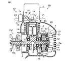
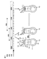
図2は、エンジンユニットEUの概略構成を模式的に示す部分断面図である。エンジンユニットEUは、車両用4ストロークエンジンユニットであり、より具体的には、鞍乗型車両1に搭載可能なエンジンユニットである。
エンジンユニットEUは、4ストローク単気筒エンジン本体10と、回転電機20とを備えている。4ストローク単気筒エンジン本体10(以下「エンジン本体10」という。)は、1つの気筒を有する単気筒の4ストロークエンジンである。
FIG. 2 is a partial cross-sectional view schematically showing a schematic configuration of the engine unit EU. The engine unit EU is a vehicle four-stroke engine unit, and more specifically, an engine unit that can be mounted on the saddle riding
The engine unit EU includes a four-stroke single cylinder engine
エンジン本体10は、クランクケース11と、シリンダ12と、ピストン13と、コネクティングロッド14と、クランクシャフト15とを備えている。
ピストン13は、シリンダ12内に往復移動自在に設けられている。クランクシャフト15は、クランクケース11内に回転可能に設けられている。コネクティングロッド14は、ピストン13とクランクシャフト15とを接続しており、ピストン13の往復運動をクランクシャフト15に伝達する。クランクシャフト15は、一対のベアリング17を介して、クランクケース11に回転自在に支持されている。
The
The
クランクシャフト15の一端部15aには、回転電機20が取り付けられている。これにより、回転電機20は、クランクシャフト15に対して動力伝達可能に結合されている。クランクシャフト15の他端部15bには、変速機CVTが取り付けられている。変速機CVTは、入力の回転速度に対する出力の回転速度の比である変速比を変更する。
シリンダ12の上部には、シリンダヘッド16が取り付けられている。シリンダ12とシリンダヘッド16とピストン13とによって、燃焼室21が区画される。シリンダヘッド16には、吸気バルブIVと、燃料噴射装置18と、点火プラグ19と、排気バルブEVとが設けられている。シリンダヘッド16には、燃焼室21と連通する吸気路22および排気路23が形成されている。吸気バルブIVは吸気路22を開閉し、排気バルブEVは排気路23を開閉する。
A rotating
A
燃料噴射装置18は、燃料を噴射することによって、燃焼室21に燃料を供給する。吸気バルブIVは、燃焼室21への空気の流入を制御する。吸気バルブIVおよび排気バルブEVは、クランクシャフト15の位置に応じて開閉する。吸気バルブIVは、開状態となることによって、燃料を含んだ空気を燃焼室21に供給する。点火プラグ19は、燃焼室21に臨むように配置されており、燃焼室21内で火花放電を生じさせることにより、燃焼室21内に導入された空気および燃料の混合気に着火する。排気バルブEVは、開状態となることにより、燃焼後の排気をシリンダ12から排気管25へと排出させる。
The
吸気路22に接続された吸気管24には、スロットルバルブTVが配置されている。スロットルバルブTVは、燃焼室21に供給される空気の量を調整する。スロットルバルブTVの開度は、アクセル操作子8(図1参照)の操作に応じて調整される。
エンジン本体10の1燃焼サイクルには、吸気行程、圧縮行程、膨張行程、および排気行程が1回ずつ含まれる。吸気行程では、吸気バルブIVが開かれ、ピストン13が下死点に向かって移動する。その間に、燃料噴射装置18が燃料を噴射する。それによって、燃焼室21内に空気と燃料との混合気が吸入される。圧縮行程では、吸気バルブIVが閉じられた状態でピストン13が上死点(圧縮上死点)に向かって移動し、それによって、燃焼室21内の混合気が圧縮される。ピストン13が圧縮上死点位置付近にあるときに点火プラグ19が火花放電する。それにより、混合気が着火されて膨張し、ピストン13を下死点に向かって移動させる膨張行程が生じる。排気行程では排気バルブEVが開かれ、ピストン13が上死点(排気上死点)に向かって移動することにより、排ガスが排気管25へと排出される。
A throttle valve TV is disposed in the
One combustion cycle of the
エンジン本体10は、クランクシャフト15を介して回転力を出力する。クランクシャフト15の回転力は、変速機CVTを介して、車輪3b(図1参照)に伝達される。鞍乗型車両1(図1参照)は、クランクシャフト15を介してエンジン本体10から出力される回転力を受ける車輪3bによって駆動される。
図3は、図2に示す回転電機20の回転軸線に垂直な断面を示す断面図である。回転電機20は、永久磁石式回転電機であり、より具体的には、永久磁石式三相ブラシレス型発電機である。回転電機20は、さらに、永久磁石式三相ブラシレス型モータとしても機能する。
The
3 is a cross-sectional view showing a cross section perpendicular to the rotation axis of the rotating
回転電機20は、ロータ30と、ステータ40とを有する。回転電機20は、この実施形態では、ラジアルギャップ型である。また、この実施形態では、回転電機20は、アウターロータ型である。すなわち、ロータ30はアウターロータであり、ステータ40はインナーステータである。
図2および図3に表れているように、ロータ30は、ロータ本体部31を有する。ロータ本体部31は、たとえば強磁性材料からなる。ロータ本体部31は、有底筒状に構成されている。ロータ本体部31は、筒状ボス部32と、円板状の底壁部33と、筒状のバックヨーク部34とを有する。底壁部33およびバックヨーク部34は一体的に形成されている。底壁部33およびバックヨーク部34は筒状ボス部32を介してクランクシャフト15に固定されている。したがって、ロータ30は、クランクシャフト15とともに回転する。ロータ30には、電流が供給される巻線が設けられていない。底壁部33には、冷却ファンFが設けられている。
The rotating
As shown in FIGS. 2 and 3, the
ロータ30は、永久磁石部37を有する。ロータ30は、複数の磁極部37aを有している。複数の磁極部37aは、この実施形態では、永久磁石部37により形成されている。複数の磁極部37aは、バックヨーク部34の内周に設けられている。永久磁石部37は、この実施形態では、複数の永久磁石を有する。複数の磁極部37aは、複数の永久磁石のそれぞれに設けられている。ただし、永久磁石部37は、1つの環状の永久磁石によって形成することもできる。この場合、1つの永久磁石は、複数の磁極部37aが内周面に並ぶように着磁される。
The
複数の磁極部37aは、ロータ30(より具体的にはバックヨーク部34)の周方向にN極とS極とが内周面に交互に配置されるように設けられている。周方向に隣り合う磁極部37aは、磁極部対37pをなしている。この実施形態では、ステータ40と対向するロータ30の磁極数は、24個である。したがって、12個の磁極部対37pが設けられている。ロータ30の磁極数とは、ステータ40と対向する磁極の数をいう。ロータ30の永久磁石とステータ40とは、エアギャップを介して対向している。磁極部37aは、回転電機20の径方向におけるステータ40の外側に設けられている。バックヨーク部34は、径方向における磁極部37aの外側に設けられている。回転電機20は、ステータ40の歯部43の数よりも多い磁極部37aを有している。
The plurality of
ステータ40は、ステータコアSTと複数のステータ巻線Wとを有する。ステータコアSTは、周方向に間隔(この実施形態では等間隔)を空けて放射状に設けられた複数の歯部(ティース)43を有する。複数の歯部43は、ステータコアSTから径方向外側に向かって一体的に延びている。この実施形態においては、合計18個の歯部43が周方向に間隔を空けて設けられている。隣接するステータコアSTの間にスロットSLが形成されている。したがって、ステータコアSTは、周方向に間隔を空けて形成された合計18個のスロットSLを有する。前述のように、ロータ30は、歯部43の数より多い数の磁極部37aを有する。磁極部37aの数は、スロット数の4/3である。
The
各歯部43の周囲には、ステータ巻線Wが巻回されている。つまり、複数相のステータ巻線Wは、スロットSLを通るように設けられている。図3には、ステータ巻線Wが、スロットSLの中にある状態が示されている。複数相のステータ巻線Wのそれぞれは、U相、V相、W相の何れかの巻線である。ステータ巻線Wは、たとえば、U相、V相、W相の順に周方向に並ぶように配置される。
A stator winding W is wound around each
ロータ30の外面には、ロータ30の回転位置を検出させるための複数(この実施形態では11個)の被検出部38が備えられている。複数の被検出部38は、磁気作用によって検出される。複数の被検出部38は、周方向に間隔を空けてロータ30の外面に設けられている。被検出部38は、強磁性体で形成されている。
図3には、11個の被検出部38の位置と、被検出部38が設けられていない欠落位置とにそれぞれに割り当てられた番号「0」〜「23」が示されている。これらの番号は、エンジン本体10の1燃焼サイクル、すなわち、ロータ30の2回転に亘って割り当てられており、1燃焼サイクル中のクランクシャフト15の位置を表す。具体的には、番号「0」〜「11」が1回転目のクランクシャフト15の位置を表し、番号「12」〜「23」が2回転目のクランクシャフト15の位置を表す。
A plurality (11 in this embodiment) of detected
FIG. 3 shows numbers “0” to “23” assigned to the positions of the eleven detected
電磁ピックアップ50は、ロータ30の回転位置を検出するロータ位置検出装置として用いられる。電磁ピックアップ50は、複数の被検出部38と対向する位置に設けられている。電磁ピックアップ50は、被検出部38を磁気的に検出するピックアップコイル51を備えている。電磁ピックアップ50は、さらに、検出用磁石52およびコア53を備えている。番号「0」の被検出部38が電磁ピックアップ50の対向位置を通過するとき、クランクシャフト15が圧縮上死点またはその近傍の位置にある。番号「12」の被検出部38が電磁ピックアップ50の対向位置を通過するとき、クランクシャフト15が排気上死点またはその近傍の位置にある。
The
回転電機20は、エンジン本体10のクランクシャフト15と結合されている。具体的には、ロータ30は、クランクシャフト15に対し固定された速度比で回転するようクランクシャフト15と結合されている。
この実施形態では、ロータ30が、クランクシャフト15に、動力伝達機構(たとえば、ベルト、チェーン、ギア、減速機、増速機等)を介さずに取り付けられている。ロータ30は、クランクシャフト15に対し、1:1の速度比で回転する。回転電機20は、エンジン本体10の燃焼動作時にロータ30が正転方向に回転するように構成されている。
The rotating
In this embodiment, the
回転電機20は、エンジン始動時には、クランクシャフト15を正転方向に回転させてエンジン本体10を始動させるスタータモータとして機能する。また、回転電機20は、エンジン本体10が燃焼動作する場合に、エンジン本体10に駆動されて発電するジェネレータとして機能する。すなわち、回転電機20は、クランクシャフト15を正転方向に回転させてエンジン本体10を始動させる機能と、エンジン本体10が燃焼動作する場合に、エンジン本体10によって駆動されて発電する機能との双方を兼ね備えている。
The rotating
回転電機20は、鞍乗型車両1が備えるバッテリ4(図1参照)により駆動されてクランクシャフト15に回転に対する力を付与する。より具体的には、回転電機20は、クランクシャフト15を正転方向に回転駆動することができ、かつ逆転方向に回転駆動することができる。さらに、回転電機20は、バッテリ4により駆動されて、クランクシャフト15の回転方向とは逆方向の力、すなわちブレーキ力を付与することもできる。
The rotating
複数の被検出部38は、ロータ30の外面に、ロータ30の回転方向に沿って間隔を空けて配列されている。電磁ピックアップ50は、ロータ30の回転に伴って複数の被検出部38と順次対向する位置に検出領域を有している。すなわち、電磁ピックアップ50は、ロータ30の回転中に、複数の被検出部38が順次進入する検出領域に臨んで配置されている。
The plurality of detected
さらに具体的に説明すると、被検出部38は、30度の角度間隔でロータ30の外面に設けられている。図3の一点鎖線は、被検出部38が設けられた角度間隔を示している。隣り合う被検出部38どうしが測定角度θを成す角度間隔で配置されている。この実施形態では、測定角度θは30度である。
電磁ピックアップ50は、ロータ30が測定角度θ回転するごとに、複数の被検出部38のそれぞれを検出する。電磁ピックアップ50は、被検出部38のそれぞれを検出するごとに、検出信号を出力する。より正確には、被検出部38が検出領域を通って移動することにより、電磁誘導によってピックアップコイル51に起電力が生じ、それによって、検出信号が生成される。すなわち、電磁ピックアップ50は、検出領域を通る被検出部38の移動を検出して検出信号を出力する。
More specifically, the detected
The
この実施形態では、各被検出部38は、1つの磁極部対37pに対応している。複数の被検出部38は、それぞれ対応する磁極部対37pに対して同一の相対位置関係を有する。
この実施形態では、ロータ30に、11個の被検出部38が設けられている。11個の被検出部38は、ロータ30に測定角度θの間隔で配置された12の位置のうちの、11ヶ所にそれぞれ設けられている。具体的には、番号「0」〜「4」,「6」〜「11」(または「12」〜「16」,「18」〜「23」)の11ヶ所に被検出部38が配置されている。番号「5」(または「17」)は、被検出部38が配置されていない欠落位置を表す。
In this embodiment, each detected
In this embodiment, eleven detected
複数の被検出部38は、クランクシャフト15の周方向に等間隔または実質的に等間隔に位置している。欠落位置(番号「5」または「17」)を挟んで周方向に隣り合う2つの位置(番号「4」および「6」の2つの位置、または「16」および「18」の2つの位置)に配置された2個の被検出部38の間の角度間隔2θは、測定角度θの2倍である。このように、複数の被検出部38によって形成される複数の間隔の一つが他の間隔と異なるので、クランクシャフト15の1回転の中の基準位置(基準クランク位置)を検出することが可能である。この基準位置、すなわち、番号「5」および「17」が付与された欠落位置に対応して電磁ピックアップ50が生成する検出信号が基準検出信号である。
The plurality of detected
以下の説明では、被検出部38の番号を用いてクランクシャフト15の回転位置(クランク位置)を表現する場合がある。たとえば、位置「9」というときには、電磁ピックアップ50によって番号「9」の被検出部38が検出される状態(図3参照)のクランクシャフト15の回転位置を意味する。
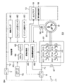
図4は、エンジンユニットEUを含む鞍乗型車両1の電気的な概略構成を示すブロック図である。エンジンユニットEUには、制御装置60およびインバータ61が備えられている。制御装置60は、インバータ61を含む鞍乗型車両1の各部を制御する。
In the following description, the rotational position (crank position) of the
FIG. 4 is a block diagram showing an electrical schematic configuration of the saddle riding
インバータ61には、回転電機20およびバッテリ4が接続されている。回転電機20がジェネレータとして機能するとき、回転電機20で発電された電力は、インバータ61を介し、電源ライン71を通ってバッテリ4に供給される。これにより、バッテリ4は、回転電機20で発電された電力によって充電される。また、回転電機20がスタータモータとして用いられるときには、バッテリ4は、電源ライン71からインバータ61を介して回転電機20に電力を供給する。電源ライン71には、メインリレー9が介装されている。したがって、バッテリ4は、メインリレー9を介して、インバータ61と接続されている。メインリレー9は、制御装置60によって開閉される。
The rotating
インバータ61は、複数の(たとえば6個の)スイッチング素子611〜616を備えている。スイッチング素子611〜616は、三相ブリッジインバータを構成している。ステータ巻線Wは、スイッチング素子611〜616と接続されている。複数のスイッチング素子611〜616は、複数相のステータ巻線Wの各相と接続されている。より詳細には、複数のスイッチング素子611〜616のうち、直列に接続された2つのスイッチング素子がハーフブリッジを構成している。各相のハーフブリッジは、バッテリ4に対し並列に接続されている。各相のハーフブリッジを構成するスイッチング素子611〜616は、複数相のステータ巻線Wの各相とそれぞれ接続されている。スイッチング素子611〜616のそれぞれは、たとえばトランジスタであり、より詳細にはFET(電界効果型トランジスタ)、IGBT(絶縁ゲートバイポーラトランジスタ)などである。
The
スイッチング素子611〜616は、複数相のステータ巻線Wとバッテリ4との間の電流の通過/遮断を制御する。
回転電機20がモータとして機能する場合、スイッチング素子611〜616のオン/オフによって複数相のステータ巻線Wのそれぞれに対する通電および通電停止が切り替えられる。
Switching
When the rotating
また、回転電機20がジェネレータとして機能する場合、スイッチング素子611〜616のオン/オフ動作によって、ステータ巻線Wのそれぞれとバッテリ4との間の電流の通過/遮断が切り替えられる。スイッチング素子611〜616のオン・オフが順次切り替えられることによって、回転電機20から出力される三相交流の整流および電圧の制御が行われる。このように、スイッチング素子611〜616は、回転電機20からバッテリ4および電装品類に出力される電流を制御する。
Further, when the rotating
このような発電動作において、電源ライン71に接続されたコンデンサ67は、回転電機20が発電動作をするときに電源ライン71に導出される電圧を平滑化する。
制御装置60は、エンジン本体10に備えられた電装品である燃料噴射装置18および点火プラグ19に接続されており、これらを制御する。また、制御装置60は、燃料ポンプ80に接続されており、その動作を制御する。燃料ポンプ80は、図示しない燃料タンクから燃料噴射装置18へと燃料を供給する。
In such a power generation operation, the
The
また、制御装置60には、電磁ピックアップ50が接続されており、当該電磁ピックアップ50が生成する検出信号が入力される。さらに、制御装置60には、スロットル位置センサ82およびエンジン温度センサ83が接続されており、これらの検出信号が入力される。スロットル位置センサ82は、スロットルバルブTVのバルブ位置、すなわちスロットル開度を検出する。スロットルバルブTVはアクセル操作子8によって操作されるので、スロットル位置センサ82は、アクセル操作子8の操作を検出することができる。エンジン温度センサ83は、エンジン本体10の温度をエンジン温度として検出する。エンジン温度センサ83は、エンジン本体10の近傍に配置される。エンジン本体10が水冷式エンジンであるときには、エンジン温度センサ83は、冷却水の温度をエンジン温度の代替指標として検出してもよい。
Further, an
さらに、制御装置60には、エンジン本体10を始動するときに使用者が操作するスタータスイッチ70が接続されている。制御装置60は、スタータスイッチ70の操作を検出すると、回転電機20の駆動を含む始動クランキング制御を実行する。
バッテリ4の電力は、電源ライン72を介して、制御装置60に供給され、さらに、燃料ポンプ80、燃料噴射装置18、点火プラグ19などの電装品に供給される。電源ライン72には、メインスイッチ7が介装されている。メインスイッチ7は、鞍乗型車両1の使用開始に際して使用者が導通操作し、鞍乗型車両1の使用終了に際して使用者が遮断操作するスイッチである。
Furthermore, a
The electric power of the battery 4 is supplied to the
メインスイッチ7が導通されると、制御装置60、燃料ポンプ80、燃料噴射装置18、点火プラグ19などがバッテリ4に接続され、作動可能となる。また、メインスイッチ7が導通しているとき、さらにメインリレー9が導通していれば、回転電機20によって生成された電力が、電源ライン71,72を介して、制御装置60、燃料ポンプ80、燃料噴射装置18、点火プラグ19などに供給可能である。
When the main switch 7 is turned on, the
制御装置60は、さらに、メインリレー9とインバータ61との間で電源ライン71に接続されている。したがって、制御装置60は、メインリレー9が遮断されているときでも、回転電機20が発生する電力を受けることができる。制御装置60は、電力が供給されていて作動可能なときに、メインリレー9の開閉を制御する。
制御装置60は、回転電機制御部62と、燃焼制御部63とを備えている。
The
The
制御装置60の燃焼制御部63は、エンジン本体10を制御する。回転電機制御部62は、回転電機20を制御する。具体的には、回転電機制御部62は、インバータ61を制御する。それにより、回転電機制御部62は、回転電機20の駆動動作および発電動作を制御する。
燃焼制御部63は、エンジン本体10の燃焼動作を制御する。燃焼制御部63は、エンジン本体10の燃焼動作を制御することによって、エンジン本体10の出力を制御する。より具体的には、燃焼制御部63は、点火プラグ19および燃料噴射装置18を制御する。
The
The
回転電機制御部62は、インバータ61に備えられた複数のスイッチング素子611〜616を制御することによって、電源ライン71を通ってバッテリ4と回転電機20との間を流れる電流を制御する。回転電機制御部62は、スイッチング素子611〜616のそれぞれのオン/オフ動作を制御することによって、回転電機20の動作を制御する。
制御装置60は、プロセッサ(CPU)64と、メモリ65(記憶装置)とを有するコンピュータで構成されている。メモリ65は、プログラムおよび演算に関するデータを記憶する。CPU64は、メモリ65に格納された制御プログラムおよびデータに基づいて演算処理を行う。回転電機制御部62および燃焼制御部63の機能は、CPU64が制御プログラムを実行することによって実現される。したがって、回転電機制御部62および燃焼制御部63のそれぞれによる動作は、具体的には、コンピュータの形態を有する制御装置60の動作である。
The rotating electrical
The
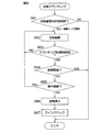
図5は、エンジン始動からエンジン停止までの制御装置60による処理の一例を説明するためのフローチャートである。鞍乗型車両1の使用を開始するとき、使用者は、メインスイッチ7をオンする。これにより、バッテリ4から制御装置60に電力が供給され、制御装置60は、処理を開始する。制御装置60は、メインリレー9を導通させ、バッテリ4とインバータ61とを接続する。
FIG. 5 is a flowchart for explaining an example of processing by the
使用者は、さらに、エンジン本体10の運転を開始させるためにスタータスイッチ70を操作する(ステップS1:YES)。これに応答して、制御装置60は、回転電機20を正転方向に駆動するための始動クランキング制御(図6参照)を開始する(ステップS2)。すなわち、制御装置60は、インバータ61のスイッチング素子611〜616を制御することにより、バッテリ4から回転電機20に電力を供給させる。それにより、クランクシャフト15の回転が始まる。
The user further operates the
クランクシャフト15の回転が始まると、電磁ピックアップ50から検出信号が生成される。制御装置60は、この検出信号を波形整形してクランクパルスを得る。制御装置60は、クランクパルスに基づいて規定されるタイミングでスイッチング素子611〜616をオン/オフ制御し、それにより、回転電機20のブラシレス駆動制御を行う。
制御装置60は、クランクパルスが所定数(たとえば2〜3個)生成されると(ステップS3:YES)、燃料ポンプ80の駆動を開始して(ステップS4)、エンジン本体10の始動に備える。
When the rotation of the
When a predetermined number (for example, 2 to 3) of crank pulses is generated (step S3: YES), the
一方、制御装置60は、クランクパルスを監視し、欠落位置(番号「5」または「17」)が到来したかどうかを判断する(ステップS5)。欠落位置が到来すると(ステップS5:YES)、制御装置60は、クランクパルスの計数を開始する(ステップS6)。そして、欠落位置を基準として、クランクパルスの計数値に基づいて、クランクシャフト15の回転位置を特定する位置特定処理を行う(ステップS7)。以後、制御装置60は、クランクパルスの計数と、その計数値に基づく位置特定処理とを常時行う。
On the other hand, the
さらに、制御装置60は、位置特定処理によって特定されたクランクシャフト15の位置に基づいてエンジン本体10の運転を制御するエンジン制御を実行する。具体的には、制御装置60は、クランクパルスの間隔に基づいてエンジン回転速度を監視し、その変動に基づいて吸気行程を検出する(ステップS8。吸気行程検出に基づく仮行程判別)。吸気行程が検出されると、それ以後は、クランクシャフト15の回転位置に基づいて、行程判別が可能となる。すなわち、位置「0」〜「11」と位置「12」〜「23」とを区別することができる。制御装置60は、クランクシャフト15の回転位置が噴射位置(たとえば位置「8」)となるのを待機し、噴射位置になると(ステップS9:YES)、燃料噴射装置18から燃料を噴射させる(ステップS10)。さらに、制御装置60は、クランクシャフト15の回転位置が点火位置になるのを待機し、点火位置になると(ステップS11:YES)、点火プラグ19を火花放電させて燃焼室21内の混合気に点火する(ステップS12)。点火位置は、上死点位置の近傍の位置(たとえば位置「0」および「12」)に設定されている。点火位置(たとえば位置「0」および「12」)は、上死点位置と一致していてもよく、また上死点位置から微少角度ずれた位置であってもよい。
Further, the
その後、制御装置60は、クランクパルスの間隔に基づいてエンジン回転速度を監視し、エンジン回転速度が完爆回転速度に達すると(ステップS13:YES)、点火用の行程判別を行う(ステップS14)。点火用の行程判別は、たとえば、1燃焼サイクル中のエンジン回転速度の変動に基づく行程判別を含む。この点火用の行程判別以前は、1回転に一度点火プラグ19の火花放電を行い、1燃焼サイクル中で2度の点火が行われる。具体的には、圧縮上死点位置付近および排気上死点位置付近の2つの位置(たとえば位置「0」および「12」)を点火位置として、これらの2つの点火位置において、点火プラグ19が火花放電する。点火用の行程判別の後は、1燃焼サイクル中に一度、すなわち、圧縮上死点位置付近の点火位置(たとえば位置「0」)において、点火プラグ19が火花放電する。
Thereafter, the
点火用の行程判別の完了後は、クランクパルスの計数によって、クランクシャフト15の2回転を30度ずつに区切った24個の回転位置「0」〜「23」が正確に判別され、噴射位置における燃料噴射(ステップS15。同期噴射制御)および点火位置における点火(ステップS16)が繰り返されて、エンジン本体10の燃焼が継続する。
エンジン本体10が始動されると、制御装置60は、アイドル停止制御を実行する。すなわち、鞍乗型車両1が信号待ち等で停車してアイドル停止条件が充足されると(ステップS17:YES)、制御装置60は、燃料噴射制御および点火制御を中断し、エンジン本体10の燃焼を停止させる(ステップS18)。この状態がアイドル停止状態である。
After completion of the ignition stroke determination, 24 rotation positions “0” to “23” obtained by dividing the two rotations of the
When the
アイドル停止条件は、次の条件A1〜A4の全てが所定の継続時間(たとえば3秒間)継続することであってもよい。
A1:スロットル開度が全閉開度
A2:車速が所定値(たとえば3km/h)以下
A3:エンジン回転速度がアイドル回転速度域(たとえば2500rpm以下)
A4:エンジン温度が所定値(たとえば60℃)以上
クランクシャフト15の回転が停止すると、制御装置60は、スイングバック制御(ステップS19)を実行する。
The idle stop condition may be that all of the following conditions A1 to A4 continue for a predetermined duration (for example, 3 seconds).
A1: Throttle opening is fully closed A2: Vehicle speed is a predetermined value (for example, 3 km / h) or less A3: Engine rotation speed is in an idle rotation speed range (for example, 2500 rpm or less)
A4: The engine temperature is equal to or higher than a predetermined value (for example, 60 ° C.) When the rotation of the
アイドル停止でなく、使用者がメインスイッチ7をオフしたときも(ステップS20:YES)、制御装置60は、燃料噴射制御および点火制御を中断し、エンジン本体10の燃焼を停止させる(ステップS21)。このとき、制御装置60は、メインスイッチ7がオフされた後もメインリレー9をオン状態に保持してバッテリ4との接続を保持し、エンジン本体10を停止させるための制御を行う(ステップS21)。さらに、制御装置60は、クランクシャフト15の回転が停止すると、スイングバック制御(ステップS22)を実行する。このスイングバック制御(ステップS22)の後、制御装置60は、メインリレー9をオフし(ステップS23)、バッテリ4との接続を遮断する。
Even when the user turns off the main switch 7 instead of the idling stop (step S20: YES), the
エンジン本体10を停止させる際に、クランクシャフト15の回転を速やかに停止させるために、制御装置60は、ブレーキ制御を行ってもよい。ブレーキ制御とは、インバータ61のスイッチング素子611〜616を制御することによって、回転電機20にクランクシャフト15の回転方向とは反対のトルクを発生させる制御である。また、クランクシャフト15の回転が停止した後、スイングバック制御(ステップS19,S21)に先立って、制御装置60は、ステータ巻線Wに一定時間通電して停止位置制御を行ってもよい。停止位置制御は、クランクシャフト15の位置を12個の回転位置「0」〜「11」(または「12」〜「23」)のいずれかの位置に正確に導くための制御である。
When the
図6は、始動クランキング制御の例を説明するためのフローチャートである。制御装置60は、スタータスイッチ70が操作されると、その操作継続時間を計測する。そして、その操作継続時間が始動意思判定時間を超えて操作されると(ステップS61:YES)、制御装置60は、回転電機20に通電してクランクシャフト15を正転方向に駆動するための正転駆動を行う(ステップS62)。すなわち、制御装置60は、正転パターンでインバータ61のスイッチング素子611〜616をオン/オフ制御する。操作継続時間が始動意思判定時間を超えないときには(ステップS61:NO)、制御装置60は、始動クランキング制御を終える。すなわち、この実施形態では、スタータスイッチ70の始動意思判定時間を超える継続操作は、始動トリガ操作の一例である。そして、スタータスイッチ70は、クランキングを開始させるために使用者によって操作される操作子の一例である。
FIG. 6 is a flowchart for explaining an example of the start cranking control. When the
前記始動意思判定時間は、使用者にエンジン始動の意思があることを判定するのに必要充分な長さの時間に設定される。すなわち、始動意思判定時間は、使用者が不用意にスタータスイッチ70に触れてしまった場合のような、意図しない操作の継続時間よりも長く設定される。また、始動意思判定時間は、使用者が始動意思を持って意図的にスタータスイッチ70を操作するときの継続操作時間以下またはそれよりも短い時間に設定される。また、始動意思判定時間は、使用者がスタータスイッチ70に対して意図しない操作を行ったときの継続操作時間以上またはそれよりも長い時間に設定される。始動意思判定時間は、たとえば0.2秒程度に設定されてもよい。
The start intention determination time is set to a time length sufficient to determine that the user has an intention to start the engine. That is, the start intention determination time is set longer than the duration of unintended operation, such as when the user touches the
正転駆動(ステップS62)を開始した後、制御装置60は、正転駆動が開始された後の継続時間(クランキング継続時間)を計測し、このクランキング継続時間が所定のクランキング制限時間を超えたかどうかを判断する(ステップS63)。クランキング継続時間がクランキング制限時間を超えない間は(ステップS63:NO)、制御装置60は、始動クランキング制御を継続し、回転電機20を正転方向に駆動する(ステップS62)。
After starting the forward rotation drive (step S62), the
クランキング継続時間がクランキング制限時間を超えると(ステップS63:YES)、制御装置60は、エンジン本体10が燃焼を開始したかどうかを判断する(ステップS64)。この判断は、エンジン回転速度が完爆回転速度に達しているかどうかの判定であってもよい。エンジン本体10が燃焼を開始していれば(ステップS64:YES)、制御装置60は、始動クランキング制御を終える。この場合、制御装置60は、回転電機20への通電を停止して、正転駆動を終えてもよい。また、制御装置60は、さらに回転電機20の正転駆動を継続して、エンジン本体10の運転状態を安定化させるための始動アシスト制御を行ってもよい。
When the cranking continuation time exceeds the cranking limit time (step S63: YES), the
クランキング制限時間までクランキングを継続したにも拘わらず、エンジン本体10の燃焼が開始していないときには(ステップS64:NO)、制御装置60は、スタータスイッチ70の操作が継続しているかどうかを判断する(ステップS65)。スタータスイッチ70の操作が解除されていれば(ステップS65:NO)、制御装置60は、エンジン本体10の燃焼が開始していなくても、回転電機20への通電を停止する(ステップS66)。その後、制御装置60は、スイングバック制御を行う(ステップS67)。
When the combustion of the
一方、スタータスイッチ70の操作が継続しているときには(ステップS65:YES)、制御装置60は、始動クランキング制御を継続し、回転電機20を正転方向に駆動する(ステップS62)。その間にエンジン本体10の燃焼開始が確認されれば(ステップS64:YES)、制御装置60は、始動クランキング制御を終える。スタータスイッチ70の操作継続が解除されるまでにエンジン本体10が燃焼開始しないときには(ステップS64:NO)、スタータスイッチ70の操作が解除されると(ステップS65:NO)、回転電機20への通電が停止される(ステップS66)。その後、制御装置60は、スイングバック制御を行う(ステップS67)。
On the other hand, when the operation of the
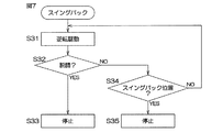
図7は、スイングバック制御(ステップS19,S22,S67)の一例を説明するためのフローチャートである。制御装置60は、インバータ61のスイッチング素子611〜616を逆転パターンで駆動することによって、回転電機20を逆転方向に駆動する(ステップS31)。それにより、クランクシャフト15が逆転方向に回転し始める。
制御装置60は、クランクシャフト15の逆転方向への回転を判別する逆転判別を実行する。バッテリ4の電圧が低いと、インバータ61を通じてステータ巻線Wに相電流を印加してもクランクシャフト15の回転が追従せず、脱調する場合がある。そこで、制御装置60は、逆転判別を実行する。より具体的には、制御装置60は、脱調が生じているかどうかを判定する(ステップS32)。たとえば、制御装置60は、電磁ピックアップ50が所定時間以上検出信号を生成しない場合、すなわち、クランクパルスが所定時間以上生じない場合に、脱調が生じていると判断してもよい。脱調が生じると(ステップS32:YES)、制御装置60は、回転電機20の駆動制御を停止し(ステップS33)、スイングバックを中止する。
FIG. 7 is a flowchart for explaining an example of the swing back control (steps S19, S22, S67). The
The
脱調が生じていないと判断されると(ステップS32:NO)、すなわち、クランクシャフト15が回転していると判断されると、制御装置60は、クランクシャフト15の位置が、所定のスイングバック位置(たとえば位置「7」)かどうかを判断する(ステップS34)。クランクシャフト15の位置は、クランクパルスの計数(逆転方向への回転のときには計数値を減じる計数)する位置特定処理によって得られる。クランクシャフト15の位置がスイングバック位置に達するまで回転電機20が逆転駆動され、スイングバック位置に達すると(ステップS34:YES)、回転電機20の駆動が停止される(ステップS35)。
If it is determined that step-out has not occurred (step S32: NO), that is, if it is determined that the
スイングバック位置は、直前の圧縮上死点位置の手前(逆転方向に関する手前)に設定されることが好ましい。クランクシャフトがスイングバック位置まで逆転された後、前述の停止位置制御が行われることが好ましい。この停止位置制御により、クランクシャフト15を12個の回転位置「0」〜「11」(または「12」〜「23」)のいずれかの位置に正確に導くことができ、多くの場合には、スイングバック位置に制御できる。
The swingback position is preferably set to a position before the immediately preceding compression top dead center position (before the reverse rotation direction). It is preferable that the stop position control described above is performed after the crankshaft is reversed to the swingback position. By this stop position control, the
電磁ピックアップ50は、被検出部38の移動に伴う電磁誘導を利用しているため、クランクシャフト15の回転停止直前には検出信号を生成しないおそれがあり、正確な位置情報が失われる可能性がある。したがって、エンジン停止時(ステップS18,S21)に制御装置60が認識するクランクシャフト15の位置、およびスイングバック動作停止時(ステップS35)に制御装置60が認識するクランクシャフト15の位置には誤差が含まれる可能性がある。しかし、スイングバック動作には、さほどの正確さは要求されないので、スイングバック後のクランクシャフト15の位置がスイングバック位置(目標位置)から多少ずれていても問題はない。
Since the
図8は、アイドル停止状態からの再始動に伴う制御装置60の処理の一例を説明するためのフローチャートである。アイドル停止状態において、制御装置60は、再始動制御を実行する。すなわち、アイドル停止状態において、再始動条件が充足されると(ステップS41:YES)、制御装置60は、回転電機20を正転方向に駆動するための再始動クランキング制御(図9参照)を開始する(ステップS42)。すなわち、制御装置60は、インバータ61のスイッチング素子611〜616を正転パターンで制御することにより、バッテリ4から回転電機20に電力を供給させる。それにより、クランクシャフト15の正転方向への回転が始まる。
FIG. 8 is a flowchart for explaining an example of processing of the
クランクシャフト15の回転が始まると、電磁ピックアップ50から検出信号が生成される。制御装置60は、この検出信号を波形整形してクランクパルスを得る。制御装置60は、クランクパルスに基づいて規定されるタイミングでスイッチング素子611〜616を正転パターンでオン/オフ制御し、それにより、回転電機20を正転方向に駆動する。
When the rotation of the
また、制御装置60は、再始動条件が充足されると(ステップS41:YES)、クランクパルスの生成を待たずに、燃料ポンプ80の駆動を開始し(ステップS43)、早期の燃料噴射に備える。すなわち、再始動条件が充足されると、制御装置60は、クランクシャフト15の回転開始を待たずに、燃料ポンプ80を駆動開始する。
再始動条件は、たとえば、スロットル位置センサ82によって検出されるスロットル開度が所定開度以上となったことを含む。この場合、使用者がアクセル操作子8を所定角度以上回動操作することが、再始動条件である。
When the restart condition is satisfied (step S41: YES), the
The restart condition includes, for example, that the throttle opening detected by the
インバータ61を通じてステータ巻線Wに相電流を印加してもクランクシャフト15の回転が追従せず、脱調して、クランクシャフト15を正確に回転させることができないおそれがある。そこで、制御装置60は、クランクシャフト15の正転方向への回転開始を判別する正転判別を実行する。具体的には、制御装置60は、クランクシャフト15が相電流に同期して回転しているかどうかを判断するための正転同期回転判定を実行する(ステップS44)。たとえば、制御装置60は、電磁ピックアップ50の検出信号のタイミングが、インバータ61のスイッチング素子611〜616のオン/オフタイミングに対する適正タイミングからずれている場合に、正転方向に同期回転していないと判断してもよい。正転方向への同期回転が検出されない場合には、制御装置60は、回転電機20の駆動制御を停止し、再度、回転電機20の正転駆動(ステップS42)を試みる。こうして、クランクシャフト15が正転方向に同期回転するまで、正転駆動(ステップS42)が繰り返される。
Even if a phase current is applied to the stator winding W through the
クランクシャフト15が正転方向に同期回転すると(ステップS44:YES)、制御装置60は、始動非同期噴射制御を実行する。具体的には、制御装置60は、始動非同期噴射実行条件の成否を判断する(ステップS45)。非同期噴射とは、欠落位置の検出や吸気行程検出に基づく仮行程判別がされるよりも前に燃料噴射装置18が燃料を噴射することをいう。
When the
始動非同期噴射実行条件は、たとえば、バッテリ4の電圧に関するバッテリ電圧条件、エンジン本体10の温度に関する条件であるエンジン温度条件、および非同期噴射の回数制限に関する条件である非同期噴射回数制限条件のうちの一つ以上を含む。
バッテリ電圧条件は、バッテリ電圧が閾値以上であることであってもよい。バッテリ電圧が低いときには、直前のエンジン停止時にスイングバック制御が適切に行われていない懸念があるので、非同期噴射を回避することが好ましい。具体的には、バッテリ電圧が低いと、クランクシャフト15をスイングバック位置まで適切に逆転させられない可能性がある。また、停止位置制御が不十分である可能性もある。
The start asynchronous injection execution condition is, for example, one of a battery voltage condition regarding the voltage of the battery 4, an engine temperature condition that is a condition regarding the temperature of the
The battery voltage condition may be that the battery voltage is equal to or higher than a threshold value. When the battery voltage is low, there is a concern that swingback control is not properly performed when the engine is stopped immediately before, so it is preferable to avoid asynchronous injection. Specifically, if the battery voltage is low, the
エンジン温度条件は、エンジン温度が下限温度以上であることを含む。エンジン温度が過度に低いと、非同期噴射によって噴射された燃料が適切に気化せず、燃焼不良となるおそれがある。エンジン温度条件は、エンジン温度が上限温度以下であることを含んでいてもよい。エンジン温度が高いと、圧縮行程において、点火前に自己着火するおそれがある。エンジン温度は、エンジン温度センサ83によって検出される。
The engine temperature condition includes that the engine temperature is equal to or higher than the lower limit temperature. If the engine temperature is excessively low, the fuel injected by asynchronous injection may not be properly vaporized, resulting in poor combustion. The engine temperature condition may include that the engine temperature is equal to or lower than the upper limit temperature. If the engine temperature is high, there is a risk of self-ignition before ignition in the compression stroke. The engine temperature is detected by an
非同期噴射回数制限条件は、非同期噴射の回数を上限回数(たとえば1回)以下に制限する条件である。行程判別までに時間を要すると非同期噴射が繰り返されるおそれがある。その場合に、過剰な燃料が供給され、点火プラグ19にプラグかぶりが生じるおそれがある。したがって、非同期噴射回数を制限することが適切である。
始動非同期噴射実行条件が充足されると(ステップS45:YES)、制御装置60は、その直後のクランクパルスの入力に応答して(ステップS46:YES)、燃料噴射装置18から燃料を非同期噴射させる(ステップS47)。このときに噴射される燃料の量は、同期噴射のときとは異なる規則に従って設定される。たとえば、スロットル開度を変数としたマップが、同期噴射用および非同期噴射用の二種類準備される。同期噴射のときには同期噴射用マップに従って燃料噴射量が決定され、非同期噴射のときには非同期噴射用マップに従って燃料噴射量が決定される。
The condition for limiting the number of asynchronous injections is a condition for limiting the number of asynchronous injections to an upper limit number (for example, one time) or less. If it takes time to determine the stroke, asynchronous injection may be repeated. In that case, excessive fuel is supplied, and the
When the start asynchronous injection execution condition is satisfied (step S45: YES), the
始動非同期噴射実行条件が充足されなければ(ステップS45:NO)、非同期噴射(ステップS47)は省かれる。
制御装置60は、クランクパルスを監視し、欠落位置が到来したかどうかを判断する(ステップS48)。欠落位置が到来すると、制御装置60は、クランクパルスの計数を開始する(ステップS49)。そして、欠落位置を基準として、クランクパルスの計数値に基づいて、クランクシャフト15の回転位置を特定する位置特定処理を行う(ステップS50)。以後、制御装置60は、クランクパルスの計数およびそれに基づく位置特定処理を常時行う。
If the start asynchronous injection execution condition is not satisfied (step S45: NO), the asynchronous injection (step S47) is omitted.
The
さらに、制御装置60は、初爆点火制御を行う。すなわち、位置特定処理(ステップS50)によって、点火位置(初爆点火位置)の到来が検出されると(ステップS51:YES)、制御装置60は、点火プラグ19の火花放電を生じさせる(ステップS52)。非同期噴射(ステップS47)がされていれば、燃焼室21内に燃料が導入されているので、燃焼が生じる。
Further, the
スイングバック位置は予め定められているので、最初の欠落位置が到来すると、正確な行程判別が可能になる。そのため、アイドル停止からの再始動のときには、吸気行程検出に基づく仮行程判別(図5のステップS8参照)を省くことができる。
その後は、制御装置60は、クランクパルスの間隔に基づいてエンジン回転速度を監視し、エンジン回転速度が完爆回転速度に達すると(ステップS53:YES)、点火用の行程判別を行う(ステップS54)。点火用の行程判別以前は、1回転に一度点火プラグ19の火花放電を行い、1燃焼サイクル中で2度の点火が行われる。
Since the swingback position is determined in advance, when the first missing position arrives, accurate stroke determination becomes possible. Therefore, at the time of restart from idle stop, it is possible to omit provisional stroke determination (see step S8 in FIG. 5) based on intake stroke detection.
Thereafter, the
点火用の行程判別の完了後は、クランクパルスの計数によって、クランクシャフト15の2回転を30度ずつに区切った24個の回転位置「0」〜「23」が正確に判別され、噴射位置における燃料噴射(ステップS55。同期噴射制御)および点火位置における点火(ステップS56)が繰り返されて、エンジン本体10の燃焼が継続する。
この後のアイドル停止制御またはメインスイッチ7のオフ操作に応答する通常停止等は、図5の場合と同様である(ステップS17〜S23)。
After completion of the ignition stroke determination, 24 rotation positions “0” to “23” obtained by dividing the two rotations of the
Subsequent idle stop control or normal stop in response to an off operation of the main switch 7 is the same as in FIG. 5 (steps S17 to S23).
図9は、再始動クランキング制御の一例を説明するためのフローチャートである。図9において、前述の図6(始動クランキング制御)と同様の処理には、図6と同じステップ番号を付してある。
制御装置60は、アイドル停止状態において、アクセル操作子8が操作されると、その操作角およびその操作継続時間を計測する。具体的には、制御装置60は、スロットル位置センサ82の検出信号に基づき、アクセル操作子8が所定角度を超えて操作されたかどうかを判断する。この所定角度は、たとえば、スロットルバルブTVがバタフライバルブである場合に、その弁体の所定角変位(たとえば1度)に相当するアクセル操作子8の操作角に等しく設定されてもよい。実際には、アクセル操作子8には遊びが設けられているから、アクセル操作子8が遊び範囲を超えて操作されなければ、スロットル位置は変動しない。したがって、前述の所定角度には、アクセル操作子8の遊び範囲も含まれる。そのため、アクセル操作子8が前記所定角度を超えて操作される場合には、その操作継続時間が比較的短くても、使用者に再始動の意思があると判断できる。
FIG. 9 is a flowchart for explaining an example of restart cranking control. In FIG. 9, the same step numbers as in FIG. 6 are assigned to the same processes as those in FIG. 6 (starting cranking control) described above.
When the
制御装置60は、アクセル操作子8が前記所定角度を超えて操作されている状態が再始動意思判定時間を超えると(ステップS71:YES)、回転電機20に通電してクランクシャフト15を正転方向に駆動するための正転駆動を行う(ステップS62)。すなわち、制御装置60は、正転パターンでインバータ61のスイッチング素子611〜616をオン/オフ制御する。アクセル操作子8の操作角が前記所定角度を超えた状態が再始動意思判定時間を超えて継続しないときは(ステップS71:NO)、制御装置60は、再始動クランキング制御を終える(ステップS71:NO)。すなわち、この実施形態では、所定角度を超えるアクセル操作子8の操作であって、再始動意思判定時間を超える継続操作が、再始動トリガ操作の一例である。
When the state in which the
前記再始動意思判定時間は、使用者にエンジン再始動の意思があることを判定するのに必要充分な長さの時間に設定される。すなわち、再始動意思判定時間は、使用者が不用意にアクセル操作子8に触れてしまった場合のような、意図しない操作の継続時間よりも長く設定される。また、再始動意思判定時間は、使用者が再始動意思を持って意図的にアクセル操作子8を操作するときの継続操作時間以下またはそれよりも短い時間に設定される。再始動意思判定時間は、たとえば10ミリ秒程度に設定されてもよい。
The restart intention determination time is set to a time length sufficient to determine that the user has an intention to restart the engine. That is, the restart intention determination time is set longer than the duration of unintended operation, such as when the user carelessly touches the
正転駆動を開始した以後の制御装置60の処理は、始動クランキング制御の場合と同様である(ステップS62〜S67)。
図10Aおよび図10Bは、通常始動時の動作例を説明するための図である。図10Aおよび図10Bは、一連の動作例を示しており、図10Aの動作に続く動作が図10Bに表されている。
The processing of the
FIG. 10A and FIG. 10B are diagrams for explaining an operation example at the normal start. 10A and 10B show a series of operation examples, and an operation following the operation of FIG. 10A is shown in FIG. 10B.
1燃焼サイクルの回転区間、すなわち720度(2回転)の回転区間内のクランクシャフト15の回転位置は、回転区間を24等分する位置「0」〜「23」で、電磁ピックアップ50の検出信号を用いて検出される。位置「5」および「17」が欠落位置(基準クランク位置)であり、位置「0」が圧縮上死点位置の付近に設定された点火位置である。位置「12」は、排気上死点の付近に設定された位置である。行程判別(図5のステップS14参照)の完了前には、位置「0」に加えて位置「12」でも点火が行われる。
The rotation position of the
この動作例では、位置「5」〜「12」の区間で排気バルブEVが開かれ、位置「11」〜「18」の区間で吸気バルブIVが開かれる。たとえば、位置「8」が噴射位置である。スイングバック位置(目標位置)は、逆転方向にクランクシャフト15を回転した場合に圧縮上死点位置付近の点火位置「0」よりも手前となる位置であり、たとえば位置「7」である。スイングバック位置は、当該スイングバック位置からクランクシャフト15を正転方向に回転させたときに最初の欠落位置(基準クランク位置)の次の上死点が圧縮上死点となるように、定められている。より具体的には、スイングバック位置は、噴射位置「8」とその直前の圧縮上死点(位置「0」付近)との間に定めることが好ましく、噴射位置「8」寄りの位置であればさらに好ましい。さらに具体的には、スイングバック位置は、噴射位置「8」の直前の位置「7」であることが好ましい。
In this operation example, the exhaust valve EV is opened in the section of the positions “5” to “12”, and the intake valve IV is opened in the section of the positions “11” to “18”. For example, the position “8” is the injection position. The swingback position (target position) is a position that is in front of the ignition position “0” in the vicinity of the compression top dead center position when the
クランクシャフト15が位置「7」(スイングバック位置)にあると、回転電機20を正転方向に駆動したとき、噴射位置「8」が到来した後に欠落位置「17」が到来し、ここからクランクパルスの計数が始まる。そのため、スイングバック位置「7」の直後の噴射位置「8」では同期噴射を行うことができない。したがって、最初の圧縮上死点位置付近の点火位置「0」では、燃焼室21内に燃料が存在しないので、点火プラグ19が点火しても燃焼が生じない。
When the
最初の圧縮上死点位置を過ぎて、吸気行程検出に基づく仮行程判別が終了すると、次の噴射位置「8」では同期噴射が行われる。したがって、次の圧縮上死点位置付近の点火位置「0」で点火プラグ19が点火すると、燃焼が生じ、エンジン本体10の運転が始まる。
このように、スイングバック位置「7」から2燃焼サイクル目で初爆が生じる。
When the provisional stroke determination based on the intake stroke detection ends after the first compression top dead center position, synchronous injection is performed at the next injection position “8”. Therefore, when the
Thus, the first explosion occurs in the second combustion cycle from the swingback position “7”.
スイングバック位置「7」から回転電機20に通電してクランクシャフト15を正転方向に駆動する場合、最初の点火位置「0」(圧縮上死点位置)までに要する時間は、たとえば0.4秒程度である。また、その点火位置「0」から、初爆が生じる次の点火位置「0」(2回目の圧縮上死点位置)までのクランクシャフト15の回転に要する時間は、たとえば0.2秒程度である。
When the rotating
したがって、クランキング制限時間(図6のステップS63)は、0.6秒以上に設定することが好ましい。すなわち、クランクシャフト制限時間は、スイングバック位置から最初の圧縮上死点位置までの所要時間と、その直後の1燃焼サイクル分の所要時間との和以上に定めることが好ましい。換言すれば、スイングバック位置から2回目の圧縮上死点位置までの所要時間以上に定めることが好ましい。始動を確実にするためには、スイングバック位置から最初の圧縮上死点までの所要時間と、その直後の2燃焼サイクル分の所要時間との和程度(たとえば0.8秒程度)またはそれ以上の時間にクランキング制限時間を定めるとよい。換言すれば、スイングバック位置から3回目の圧縮上死点までの所要時間程度(たとえば0.8秒程度)またはそれ以上の時間にクランキング制限時間を定めるとよい。これにより、2回の着火機会を確保できるので、確実なエンジン始動が可能になる。 Therefore, it is preferable to set the cranking limit time (step S63 in FIG. 6) to 0.6 seconds or more. That is, the crankshaft time limit is preferably set to be equal to or greater than the sum of the time required from the swingback position to the first compression top dead center position and the time required for one combustion cycle immediately after that. In other words, it is preferable that the time is set to be longer than the required time from the swing back position to the second compression top dead center position. In order to ensure starting, the sum of the time required from the swingback position to the first compression top dead center and the time required for the next two combustion cycles (for example, about 0.8 seconds) or more It is advisable to set the cranking limit time at In other words, it is preferable to set the cranking limit time to the time required from the swing back position to the third compression top dead center (for example, about 0.8 seconds) or more. As a result, two ignition opportunities can be secured, so that the engine can be reliably started.
図11は、アイドルストップ状態からのエンジン再始動時の動作例を説明するための図である。アイドル停止からエンジン再始動までの時間は一般に長くないので、アイドル停止状態の間にクランクシャフト15の回転位置が大きく変わることはない。したがって、再始動時には、クランクシャフト15はスイングバック位置「7」またはその近傍にある。
FIG. 11 is a diagram for explaining an operation example when the engine is restarted from the idle stop state. Since the time from the idle stop to the engine restart is generally not long, the rotational position of the
この状態から、回転電機20を正転方向に駆動すると、電磁ピックアップ50は遅くとも欠落位置「17」よりも前に検出信号を生成し、したがって、クランクパルスが発生する。クランクパルスに応答して、非同期噴射が行われる。その後、欠落位置「17」が到来し、ここからクランクパルスの計数が始まる。しかも、再始動時のスイングバック位置が位置「7」またはその近傍にあるので、最初の欠落位置は位置「5」ではなく位置「17」であるとの仮定が成り立つ。したがって、最初に検出される欠落位置を位置「17」と見なすことができ、それにより、それ以降、行程判別(クランク位置の特定)が可能になる。
When the rotating
制御装置60は、最初の圧縮上死点位置付近の点火位置「0」(初爆点火位置)で、点火プラグ19を点火させる。このとき、非同期噴射によって既に燃焼室21内に燃料が導入されているので、初爆を起こさせることができ、エンジン本体10の運転が始まる。
こうして、最初の圧縮上死点位置から燃焼を開始させることができ、スイングバック位置「7」から1燃焼サイクル内に初爆を生じさせることができる。これにより、アイドル停止状態からの再始動を速やかに行える。通常の始動時と比較すると、1燃焼サイクル分早いエンジン始動が可能である。
The
Thus, combustion can be started from the first compression top dead center position, and the first explosion can be generated within one combustion cycle from the swingback position “7”. Thereby, restart from an idle stop state can be performed rapidly. Compared with a normal start, the engine can be started earlier by one combustion cycle.
スイングバック位置「7」から回転電機20を正転方向に駆動すると、多くの場合には、スイングバック位置「7」の次の位置「8」(同期噴射のための噴射位置)で最初のクランクパルスが発生する。したがって、この実施形態では、同期噴射と同じまたはほぼ同じタイミングで非同期噴射を行うことができる。
スイングバック位置「7」から回転電機20に通電してクランクシャフト15を正転方向に駆動する場合、最初の点火位置「0」(圧縮上死点位置)までに要する時間は、たとえば0.4秒程度である。ここで初爆が生じるので、再始動クランキング制御におけるクランキング制限時間は、クランキング制限時間(図9のステップS63)は、0.4秒程度以上に設定することが好ましい。すなわち、クランクシャフト制限時間は、スイングバック位置から最初の圧縮上死点位置までの所要時間以上に定めることが好ましい。換言すれば、スイングバック位置から1回目の圧縮上死点位置までの所要時間以上に定めることが好ましい。
When the rotary
When the rotating
始動を確実にするためには、スイングバック位置から最初の圧縮上死点までの所要時間と、その直後の1燃焼サイクル分の所要時間(たとえば0.2秒程度)との和程度(たとえば0.6秒程度)またはそれ以上の時間にクランキング制限時間を定めるとよい。換言すれば、スイングバック位置から2回目の圧縮上死点までの所要時間程度(たとえば0.6秒程度)またはそれ以上の時間にクランキング制限時間を定めるとよい。これにより、2回の着火機会を確保できるので、確実なエンジン始動が可能になる。 In order to ensure start-up, the required time from the swingback position to the first compression top dead center and the required time for one combustion cycle (for example, about 0.2 seconds) immediately after that (for example, 0) It is advisable to set the cranking time limit to about 6 seconds) or longer. In other words, it is preferable to set the cranking limit time to the time required from the swing back position to the second compression top dead center (for example, about 0.6 seconds) or longer. As a result, two ignition opportunities can be secured, so that the engine can be reliably started.
通常の始動クランキング制御(図6参照)と、再始動クランキング制御(図9参照)とで異なる長さのクランキング制限時間を用いてもよいし、同じ長さのクランキング制限時間を適用してもよい。同じ長さのクランキング制限時間(たとえば0.8秒程度)を適用すれば、アイドル停止状態からの再始動クランキングの際の着火機会が多くなるので、エンジン始動の確実性を高めることができる。 A different cranking time limit may be used for normal start cranking control (see FIG. 6) and restart cranking control (see FIG. 9), or the same length cranking time limit may be applied. May be. If the cranking limit time of the same length (for example, about 0.8 seconds) is applied, the ignition opportunity at the time of restart cranking from the idling stop state increases, so the reliability of engine start can be improved. .
図12A〜図12Eは、始動クランキング制御によるクランキング動作例を示す。これらのクランキング動作例では、始動意思判定時間が0.2秒に設定されており、クランキング制限時間が0.8秒に設定されている。
図12Aに示すように、スタータスイッチ70の操作継続時間が0.2秒に満たないときには、回転電機20の正転駆動(クランキング)が行われない。したがって、エンジン本体10の燃焼も開始しない。
12A to 12E show examples of the cranking operation by the start cranking control. In these cranking operation examples, the start intention determination time is set to 0.2 seconds, and the cranking limit time is set to 0.8 seconds.
As shown in FIG. 12A, when the operation continuation time of the
図12Bに示すように、スタータスイッチ70の操作継続時間が0.2秒を超えると、クランキングが実行される。クランキング中にスタータスイッチ70の操作が解除されても、0.8秒(クランキング制限時間)が経過するまで、クランキングは継続される。0.8秒の経過までにエンジン本体10の燃焼が開始すれば、0.8秒のクランキング継続の後に、始動クランキング制御は終了する。その後は、回転電機20の通電が停止されてもよいし、エンジン本体10の燃焼状態が安定するまで、引き続き回転電機20の正転駆動を継続してもよい(始動アシスト制御)。
As shown in FIG. 12B, when the operation duration time of the
燃料切れなどのためにエンジン本体10が始動できないときには、図12Cに示すように、クランキング継続時間が0.8秒(クランキング制限時間)を超えると、クランキングが停止される。この場合には、スイングバック制御が行われ、クランクシャフト15がスイングバック位置まで逆転される。
たとえば、気温が極低温であるためにエンジン始動に時間を要する場合に、使用者は、スタータスイッチ70を長時間に渡って継続操作することがある。たとえば、図12Dおよび図12Eに示すように、クランキング継続時間が0.8秒(クランキング制限時間)を超えても、スタータスイッチ70がまだ操作され続けていることがある。このような場合には、スタータスイッチ70が操作されている間は、クランキングが継続される。その間にエンジン本体10が燃焼を開始すれば、図12Dに示すように始動クランキング制御を終了し、必要に応じて始動アシスト制御が行われる。エンジン本体10が燃焼を開始しなければ、図12Eに示すように、スタータスイッチ70の操作が解除されると、クランキングが終了し、その後、スイングバック制御が行われる。
When the engine
For example, when the temperature is extremely low and it takes time to start the engine, the user may continue to operate the
再始動クランキング制御に伴うクランキング動作例は、図12A〜図12Eのクランキング動作例に類似する。再始動クランキング制御の再始動トリガ操作は、この実施形態では、アクセル操作子8の所定角度を超える操作の継続(たとえば10ミリ秒を超える継続)である。したがって、図12A〜図12Eのクランキング動作例において、スタータスイッチ70の操作をアクセル操作子8の所定角度を超える操作と読み替える。さらに、図12A〜図12Eのクランキング動作例において、始動意思判定時間(たとえば0.2秒)を再始動意思判定時間(たとえば10ミリ秒)と読み替える。これにより、再始動クランキング制御に伴うクランキング動作例が得られる。
The cranking operation example accompanying the restart cranking control is similar to the cranking operation examples of FIGS. 12A to 12E. In this embodiment, the restart trigger operation of the restart cranking control is a continuation of an operation exceeding a predetermined angle of the accelerator operation element 8 (for example, a continuation exceeding 10 milliseconds). Therefore, in the cranking operation examples of FIGS. 12A to 12E, the operation of the
以上のように、この実施形態によれば、制御装置60は、エンジン本体10の運転を停止した後、スイングバック制御を実行して、クランクシャフト15をスイングバック位置まで逆転させる。したがって、その後のエンジン始動時には、圧縮上死点位置までにクランクシャフト15を加速する助走区間を確保できる。そのため、回転電機20が発生する駆動トルクに加えて、クランクシャフト15を含む回転系の慣性トルクを利用して、圧縮上死点を乗り越すことができる。よって、回転電機20は、大きな駆動トルクを発生する必要がなく、それに応じて小型化が可能である。換言すれば、発電機能を有する回転電機20をエンジン始動用のスタータモータとして兼用しながら、エンジン始動を支障無く行うことができる。
As described above, according to this embodiment, the
この実施形態では、使用者がスタータスイッチ70を操作して始動トリガ操作を行うと、それに応答してクランキングが始まる。すると、その後に当該始動トリガ操作がなくなっても、エンジン本体10が燃焼開始するように定めたクランキング制限時間が経過するまで、回転電機20への通電が継続される(図12B参照)。これにより、始動トリガ操作が行われると、エンジン本体10を確実に燃焼開始させることができる。すなわち、始動トリガ操作が短時間で終了してもクランキングが継続されるので、エンジン本体10の燃焼を確実に開始させることができる。
In this embodiment, when the user operates the
もしも、始動トリガ操作が短時間で終了したときに、エンジン本体10の燃焼が開始しないまま、回転電機20への通電を停止するとすれば、次にエンジン本体10を始動させるまでに、スイングバック動作が行われることになる。そのため、次の始動までの待ち時間が長くなる。したがって、使用者は、複数回の始動トリガ操作を余儀なくされるうえ、複数回の始動トリガ操作の間にスイングバック動作のための待機時間が生じてしまう。また、エンジン本体10の燃焼が開始したとしても、燃焼開始直後に回転電機20への通電が停止されると、燃焼が不安定になって、いわゆるローアイドル現象が発生するおそれがある。
If the power supply to the rotating
これに対して、この実施形態では、始動トリガ操作が短時間で終了したとしても、クランキング制限時間の間は、回転電機20はクランクシャフト15を正転方向に駆動し続ける(図12B参照)。それにより、一度の始動トリガ操作で確実にエンジン本体10の燃焼を開始させることができるから、複数回の始動トリガ操作を行う必要がなく、かつその間の待ち時間も生じない。しかも、クランキング制限時間が経過するまではクランキングが継続されるので、エンジン本体の燃焼が不安定になることを回避でき、いわゆるローアイドル現象の発生を回避できる。
On the other hand, in this embodiment, even if the start trigger operation is completed in a short time, the rotating
こうして、スイングバック動作に起因する始動時の不便を低減でき、始動性の良好なエンジンユニットEUを提供できる。
また、この実施形態では、始動トリガ操作がなくなっても回転電機20への通電が継続される一方、エンジン本体10の燃焼が開始されることなくクランキング制限時間が経過すると、回転電機20への通電が停止される(図12C参照)。これにより、始動操作トリガがなくなった場合の回転電機20への通電時間をクランキング制限時間に制限できる。それにより、エネルギー消費を制限できる。
Thus, inconvenience at the start due to the swingback operation can be reduced, and an engine unit EU having a good startability can be provided.
Further, in this embodiment, energization to the rotating
また、この実施形態では、始動トリガ操作が継続している限り、クランキング制限時間が経過した後であっても、回転電機20への通電が継続される(図12Dおよび図12E参照)。これにより、使用者の意思によって長時間のクランキングを行うことができる。たとえば、気温が低いときには、エンジン本体の燃焼開始までに長時間のクランキングが必要になる場合がある。このような場合に、使用者の意思によって長時間のクランキングを許容することができる。
In this embodiment, as long as the start trigger operation continues, energization of the rotating
また、この実施形態では、スタータスイッチ70の継続操作時間が始動意思判定時間(たとえば0.2秒)を超えると、クランキングが行われる。スタータスイッチ70の継続操作時間が始動意思判定時間に満たないときには、この操作は始動トリガ操作とは見なされない(図12A参照)。したがって、使用者が不用意にスタータスイッチ70を操作したとしても、クランキングが始まらない。これにより、使用者の意思を正確に反映してクランキングを行うことができる。
Further, in this embodiment, when the continuous operation time of the
この実施形態では、クランキングはエンジン本体10の燃焼が開始するように定めたクランキング制限時間が経過するまで継続するから、使用者がスタータスイッチ70を不用意に操作してしまったときにクランキングが行われるとすれば、使用者の望まないクランキングおよびエンジン始動が行われるおそれがある。そこで、スタータスイッチ70の継続操作時間が始動意思判定時間を超えることを条件にクランキングを開始することにより、不所望なクランキングおよびエンジン始動を回避できる。それにより、無用なエネルギー消費を回避できる。
In this embodiment, the cranking continues until the cranking time limit determined so that the combustion of the
また、この実施形態では、アイドル停止制御によってエンジン本体10が停止すると、次に回転電機20によってクランクシャフト15が正転方向に駆動されるまでに、スイングバック制御が行われる。そして、アイドル停止状態において、使用者がアクセル操作子8に対して再始動トリガ操作を行うと、クランキングが行われる。使用者がエンジン本体10の燃焼開始よりも前に再始動トリガ操作を中断しても、クランキング制限時間が経過するまでクランキングが継続される。それにより、アイドル停止からのエンジン再始動を確実に行うことができる。
In this embodiment, when the
もしも、エンジン本体10の燃焼開始前に再始動トリガ操作が中断されたときにクランキングを停止すると、次にエンジン本体10を再始動させるまでに、スイングバック動作が行われる。そのため、次の再始動までの待ち時間が長くなる。したがって、使用者は、複数回の再始動トリガ操作を余儀なくされるうえ、複数回の再始動トリガ操作の間にスイングバックのための待機時間が生じてしまう。
If the cranking is stopped when the restart trigger operation is interrupted before the combustion of the
これに対して、この実施形態では、再始動トリガ操作が短時間で終了したとしても、エンジン本体10が燃焼開始するように定めたクランキング制限時間が経過するまでクランキングが継続する。それにより、一度の再始動トリガ操作で確実にエンジン本体を再始動できる。したがって、複数回の再始動トリガ操作は不要であり、かつその間の待ち時間も生じない。こうして、スイングバック動作に起因する再始動時の不便および遅れを回避できる。
On the other hand, in this embodiment, even if the restart trigger operation is completed in a short time, the cranking is continued until the cranking limit time determined so that the
また、この実施形態では、エンジン本体10の始動に失敗したときには、スイングバック動作が行われるので、次回の始動時には、スイングバック位置からクランクシャフト15の回転を開始することができる。それにより、クランクシャフト15を含む回転系の慣性トルクを利用してエンジン本体10を始動できる。
また、この実施形態では、回転電機20のロータ30の回転情報、すなわちクランクシャフト15の位置情報が電磁ピックアップ50を用いて取得されるので、ホールICのような位置センサを用いる場合に比較して構成が安価である。その反面、電磁ピックアップ50の検出信号に基づく位置特定には時間がかかる。とくに、エンジン本体10が停止している状態から、クランクシャフト15の位置の特定が可能となるまでの時間は、ホールICのような位置センサを用いる場合に比較して長い。それに応じて、クランクシャフト15の回転が開始してからエンジン本体10の運転制御が可能になるまでの時間が長い。
Further, in this embodiment, when the engine
Further, in this embodiment, since the rotation information of the
もしも、始動トリガ操作が短時間で終了したときに、エンジン本体10の燃焼が開始しないまま、回転電機20への通電を停止するとすれば、次にエンジン本体10を始動させるまでに、スイングバック動作が行われることになる。そのうえ、電磁ピックアップ50の検出信号に基づく位置特定を経てエンジン本体10の燃焼制御の開始までの待ち時間もある。したがって、使用者は複数回の始動トリガ操作を余儀なくされるうえに、複数回の始動トリガ操作の間にスイングバック動作および位置特定のための待機時間が生じてしまう。
If the power supply to the rotating
これに対して、この実施形態では、始動トリガ操作が短時間で終了したとしても、クランキング制限時間が経過するまでは、クランキングが継続する。それにより、一度の始動トリガ操作で確実にエンジン本体10の燃焼を開始させることができるから、複数回の始動トリガ操作を行う必要がなく、上記のような長い待ち時間も生じない。したがって、電磁ピックアップ50を用いた安価な構成でありながら、スイングバック動作に起因する始動時の不便を低減できる。
On the other hand, in this embodiment, even if the start trigger operation is completed in a short time, the cranking is continued until the cranking limit time elapses. As a result, the combustion of the
この実施形態では、エンジン本体10は、単気筒4ストロークエンジン本体である。したがって、クランキング時の負荷トルクの変動が大きく、圧縮上死点位置付近で負荷トルクが最大となる。そこで、スイングバック動作を行うことで、非力な回転電機20であっても、圧縮上死点を乗り越してクランキングすることができる。
一方、4ストロークエンジン本体10は、1燃焼サイクル中に、吸気行程、圧縮行程、膨張行程および排気行程を有している。これらの行程を判別することにより、エンジン本体10の運転を適切に制御できる。他方、電磁ピックアップ50の検出信号を用いた位置特定には時間がかかるので行程判別まで時間が長い。それに応じて、エンジン本体10の始動に時間がかかる。
In this embodiment, the
On the other hand, the four-
この実施形態では、始動トリガ操作に応答してクランキングが始まると、始動トリガ操作がなくなっても、クランキング制限時間の経過までは、クランキングが継続される。したがって、一回の始動トリガ操作で確実にエンジン本体10を始動できる。それにより、クランキングが繰り返し行われることを可及的に回避できるので、電磁ピックアップ50の使用に起因する始動時の不便を低減できる。
In this embodiment, when cranking is started in response to the start trigger operation, the cranking is continued until the cranking limit time elapses even if the start trigger operation is lost. Therefore, the
また、この実施形態では、電磁ピックアップ50の検出領域に欠落位置が到達して基準検出信号が生成された後に、クランクシャフト15の位置特定が可能になる。そのため、行程判別が可能になるまでに時間がかかる。この実施形態によれば、クランキングが始まると、始動トリガ操作がなくなってもクランキング制限時間の経過までクランキングが継続されるので、始動操作のやり直しを回避できる。したがって、始動操作のやり直しに起因する待ち時間も回避できる。それにより、行程判別が可能になるまでに時間がかかるとしても、使用者はその時間を一度待機するだけであるので、実質的な不便はない。
In this embodiment, the position of the
また、この実施形態では、電磁ピックアップ50を用いた位置特定処理を利用して、スイングバック動作を正確に行うことができる。それにより、エンジン本体10の始動時には、クランクシャフト15をスイングバック位置から確実に回転開始して加速できるから、エンジン本体10を確実に始動できる。それにより、始動のやり直しを回避できる。
以上、この発明の一実施形態について説明してきたが、この発明は、さらに他の形態で実施することができる。
In this embodiment, the swing back operation can be accurately performed using the position specifying process using the
As mentioned above, although one Embodiment of this invention was described, this invention can be implemented with another form.
たとえば、前述の実施形態では、エンジン本体10の運転停止に伴ってスイングバック制御が行われている。しかし、スイングバック制御は、エンジン本体10がアイドル停止状態となってから、再始動のためにクランクシャフト15の正転方向への駆動が開始されるまでの間に行われればよい。たとえば、アイドル停止の際にはスイングバック制御は行わず、再始動条件が充足されたときに、スイングバック制御を行い、その後に回転電機20によってクランクシャフト15を正転方向に回転してもよい。
For example, in the above-described embodiment, the swing back control is performed as the operation of the
また、前述の実施形態での再始動トリガ操作は、アクセル操作子8の所定角度以上であって、かつ再始動意思判定時間を超えて継続する操作である。しかし、再始動トリガ操作は、スタータスイッチ70が再始動意思判定時間を超えて操作されたことを含んでもよい。この場合、アイドル停止状態でスタータスイッチ70が再始動意思判定時間以上操作されると、エンジン本体10を再始動するための制御が開始される。この場合の再始動意思判定時間は、アイドル停止状態でないときのスタータスイッチ70の操作に対して適用される始動意思判定時間と同じでもよく、また、それよりも短くてもよい。アイドル停止状態でないときにスタータスイッチ70が操作されると、始動クランキング制御(図6参照)が行われる。アイドル停止状態のときにスタータスイッチ70が操作されると、再始動クランキング制御(図9参照)が行われる。
In addition, the restart trigger operation in the above-described embodiment is an operation that is not less than a predetermined angle of the
また、前述の実施形態では、クランクシャフト15が正転方向に回転開始したことを判別する正転判別を行っているが、これを省いてもよい。すなわち、回転電機20の正転駆動を開始したことを条件に非同期噴射を行ってもよい。たとえば、回転電機20の正転駆動を開始し、一定時間だけ待機した後に、非同期噴射を許可し、その直後のクランクパルスに同期して非同期噴射を実行してもよい。
In the above-described embodiment, forward rotation determination is performed to determine that the
また、前述の実施形態では、通常の始動時には、非同期噴射を行っていないけれども、通常の始動時にも再始動時と同様の非同期噴射を行ってもよい。
さらに、前述の実施形態では、ロータ30上の欠落位置が電磁ピックアップ50を通過するときに基準検出信号が生成される。しかし、基準検出信号を生成させるための被検出部の配置は、これに限られない。たとえば、ロータ30の周方向の長さが他の被検出部とは異なる一つの基準被検出部を設けてもよい。
Further, in the above-described embodiment, asynchronous injection is not performed at the normal start, but asynchronous injection similar to that at the restart may be performed at the normal start.
Furthermore, in the above-described embodiment, the reference detection signal is generated when the missing position on the
また、ロータ30の回転情報を得るために、電磁ピックアップ50の代わりに、ホールIC等の回転角センサが用いられてもよい。
また、前述の実施形態では、操作時間やクランキング継続時間が各判定基準値を超えるかどうかを判断しているけれども(ステップS61,S63,S71など)、各時間が対応する判定基準値に達したかどうかを判断してもよい。いずれの判断であっても実質的な相違はない。
Further, in order to obtain the rotation information of the
In the above-described embodiment, it is determined whether the operation time or the cranking continuation time exceeds each determination reference value (steps S61, S63, S71, etc.), but each time reaches the corresponding determination reference value. You may judge whether you did. There is no substantial difference in any judgment.
また、前述の実施形態では、単気筒4ストロークエンジンを例にとったけれども、複数気筒を有する4ストロークエンジンにこの発明が適用されてもよい。
さらに、前述の実施形態では、前後2つの車輪3a,3bを有する鞍乗型車両を例にとったけれども、3つの車輪を有する鞍乗型車両など、他の形態の鞍乗型車両にもこの発明を適用できる。
In the above-described embodiment, the single-cylinder four-stroke engine is taken as an example. However, the present invention may be applied to a four-stroke engine having a plurality of cylinders.
Furthermore, in the above-described embodiment, the saddle type vehicle having the two front and
その他、特許請求の範囲に記載された事項の範囲で種々の設計変更を施すことが可能である。 In addition, various design changes can be made within the scope of matters described in the claims.
EU エンジンユニット、1 鞍乗型車両、2 車体、3a,3b 車輪、4 バッテリ、5 シート、7 メインスイッチ、10 エンジン本体、15 クランクシャフト、18 燃料噴射装置、19 点火プラグ、20 回転電機、30 ロータ、40 ステータ、38 被検出部、50 電磁ピックアップ、60 制御装置、61 インバータ、611〜616 スイッチング素子、62 回転電機制御部、63 燃焼制御部、70 スタータスイッチ、80 燃料ポンプ EU engine unit, 1 straddle type vehicle, 2 body, 3a, 3b wheels, 4 battery, 5 seats, 7 main switch, 10 engine body, 15 crankshaft, 18 fuel injection device, 19 spark plug, 20 rotating electrical machine, 30 Rotor, 40 Stator, 38 Detected part, 50 Electromagnetic pickup, 60 Control device, 61 Inverter, 611 to 616 Switching element, 62 Rotating electrical machine control part, 63 Combustion control part, 70 Starter switch, 80 Fuel pump
Claims (11)
気筒とクランクシャフトとを有する単気筒エンジン本体と、
前記クランクシャフトに対して動力伝達可能に結合され、前記クランクシャフトを回転するスタータモータ、および前記クランクシャフトの回転力によって発電するジェネレータとして兼用される回転電機と、
前記エンジン本体および前記回転電機を制御する制御装置と、を含み、
前記制御装置が、
前記エンジン本体が停止状態のときに、前記鞍乗型車両に備えられた操作子の始動トリガ操作に応答して、前記エンジン本体を始動するために前記回転電機に通電して前記クランクシャフトを正転方向に駆動する始動クランキング制御と、
前記エンジン本体が停止した後、前記クランクシャフトの正転方向への駆動を開始するまでに、前記回転電機により前記クランクシャフトを逆転方向に駆動して、前記クランクシャフトを所定のスイングバック位置まで逆転させるスイングバック制御と、を実行し、
前記制御装置は、前記始動クランキング制御において、前記操作子の始動トリガ操作がなくなっても、前記エンジン本体が燃焼開始するように定めた所定のクランキング制限時間が経過するまで前記回転電機への通電を継続する、鞍乗型車両用エンジンユニット。 An engine unit provided in a saddle-ride type vehicle,
A single-cylinder engine body having a cylinder and a crankshaft;
A starter motor that is coupled to the crankshaft so as to be able to transmit power, and that rotates the crankshaft;
A control device for controlling the engine body and the rotating electrical machine,
The control device is
When the engine main body is in a stopped state, in response to a start trigger operation of an operation element provided in the saddle riding type vehicle, the crankshaft is correctly connected by energizing the rotating electrical machine to start the engine main body. Start cranking control to drive in the rolling direction;
After the engine body stops, before the crankshaft starts to be driven in the forward rotation direction, the crankshaft is driven in the reverse rotation direction by the rotating electric machine, and the crankshaft is reversely rotated to a predetermined swingback position. Let swing back control, and
In the start cranking control, the control device supplies the rotary electric machine to the rotating electrical machine until a predetermined cranking limit time determined so that the engine body starts to burn even if the start trigger operation of the operation element is lost. A straddle-type vehicle engine unit that continues energization.
前記操作子が、前記エンジン本体のスロットルを操作するために操作者によって操作されるスロットル操作子を含み、前記始動トリガ操作が、前記スロットル操作子に対する使用者の所定の再始動トリガ操作を含み、
前記始動クランキング制御が、前記アイドル停止状態において、前記スロットル操作子に対する前記再始動トリガ操作に応答する再始動クランキング制御を含む、請求項1〜4のいずれか一項に記載の鞍乗型車両用エンジンユニット。 When the idling stop condition is satisfied, the control device executes idling stop control to stop the combustion of the engine body and to enter an idling stop state.
The operating element includes a throttle operating element operated by an operator to operate the throttle of the engine body, and the start trigger operation includes a predetermined restart trigger operation of a user with respect to the throttle operating element,
The straddle type according to any one of claims 1 to 4, wherein the start cranking control includes a restart cranking control that responds to the restart trigger operation on the throttle operator in the idle stop state. Engine unit for vehicles.
前記ロータに回転方向に間隔を空けて配置された複数の被検出部と、
前記複数の被検出部が通過する領域に検出領域を有し、前記被検出部の前記検出領域の通過に伴って検出信号を生成する電磁ピックアップと、をさらに含み、
前記制御装置が、前記電磁ピックアップが生成する検出信号を用いて、前記クランクシャフトの位置を特定する位置特定処理と、前記位置特定処理によって特定された位置を用いて、前記エンジン本体の運転を制御するエンジン制御とを実行する、請求項1〜6のいずれか一項に記載の鞍乗型車両用エンジンユニット。 A rotor that rotates with rotation of the crankshaft;
A plurality of detected parts arranged at intervals in the rotation direction on the rotor;
An electromagnetic pickup that has a detection region in a region through which the plurality of detected portions pass, and generates a detection signal along with the passage of the detection region of the detected portion;
The control device uses the detection signal generated by the electromagnetic pickup to control the operation of the engine body using the position specifying process for specifying the position of the crankshaft and the position specified by the position specifying process. The straddle-type vehicle engine unit according to any one of claims 1 to 6, wherein the engine control is executed.
前記制御装置は、前記エンジン制御において、前記位置特定処理を用いた行程判別に基づいて前記エンジン本体の運転を制御する、請求項7に記載の鞍乗型車両用エンジンユニット。 The engine body is a single cylinder four-stroke engine body,
The straddle-type vehicle engine unit according to claim 7, wherein the control device controls operation of the engine body based on stroke determination using the position specifying process in the engine control.
前記制御装置は、前記位置特定処理において、前記クランクシャフトが正転方向に回転し始めた後に前記電磁ピックアップが生成する前記基準検出信号に基づいて前記クランクシャフトの位置を特定する、請求項8に記載の鞍乗型車両用エンジンユニット。 The plurality of detected parts are configured such that the electromagnetic pickup generates a reference detection signal at a predetermined reference crank position,
9. The control device according to claim 8, wherein, in the position specifying process, the position of the crankshaft is specified based on the reference detection signal generated by the electromagnetic pickup after the crankshaft starts to rotate in the forward rotation direction. The engine unit for saddle riding type vehicles as described.
前記クランクシャフトの回転が伝達される車輪と、
鞍乗型のシートと、を含む、鞍乗型車両。 The straddle-type vehicle engine unit according to any one of claims 1 to 10,
Wheels to which rotation of the crankshaft is transmitted;
A straddle-type vehicle including a straddle-type seat.
Priority Applications (4)
| Application Number | Priority Date | Filing Date | Title |
|---|---|---|---|
| JP2018037718A JP2019152147A (en) | 2018-03-02 | 2018-03-02 | Engine unit for saddle riding-type vehicle and saddle riding-type vehicle |
| EP19158251.9A EP3533993B1 (en) | 2018-03-02 | 2019-02-20 | Method for controlling an engine unit for a straddled vehicle, engine unit and straddled vehicle |
| EP19158252.7A EP3533994B1 (en) | 2018-03-02 | 2019-02-20 | Method for controlling an engine unit for a straddled vehicle, engine unit and straddled vehicle |
| EP19158250.1A EP3533995B1 (en) | 2018-03-02 | 2019-02-20 | Method for controlling an engine unit for a straddled vehicle, engine unit and straddled vehicle |
Applications Claiming Priority (1)
| Application Number | Priority Date | Filing Date | Title |
|---|---|---|---|
| JP2018037718A JP2019152147A (en) | 2018-03-02 | 2018-03-02 | Engine unit for saddle riding-type vehicle and saddle riding-type vehicle |
Publications (1)
| Publication Number | Publication Date |
|---|---|
| JP2019152147A true JP2019152147A (en) | 2019-09-12 |
Family
ID=67948562
Family Applications (1)
| Application Number | Title | Priority Date | Filing Date |
|---|---|---|---|
| JP2018037718A Pending JP2019152147A (en) | 2018-03-02 | 2018-03-02 | Engine unit for saddle riding-type vehicle and saddle riding-type vehicle |
Country Status (1)
| Country | Link |
|---|---|
| JP (1) | JP2019152147A (en) |
Cited By (2)
| Publication number | Priority date | Publication date | Assignee | Title |
|---|---|---|---|---|
| WO2021255891A1 (en) * | 2020-06-18 | 2021-12-23 | ヤマハ発動機株式会社 | Manual-transmission straddled vehicle |
| WO2022138408A1 (en) * | 2020-12-25 | 2022-06-30 | 三菱重工メイキエンジン株式会社 | Start control device for engine |
-
2018
- 2018-03-02 JP JP2018037718A patent/JP2019152147A/en active Pending
Cited By (5)
| Publication number | Priority date | Publication date | Assignee | Title |
|---|---|---|---|---|
| WO2021255891A1 (en) * | 2020-06-18 | 2021-12-23 | ヤマハ発動機株式会社 | Manual-transmission straddled vehicle |
| WO2021256549A1 (en) * | 2020-06-18 | 2021-12-23 | ヤマハ発動機株式会社 | Manual-transmission-type straddled vehicle |
| JPWO2021256549A1 (en) * | 2020-06-18 | 2021-12-23 | ||
| JP7239785B2 (en) | 2020-06-18 | 2023-03-14 | ヤマハ発動機株式会社 | MT type straddled vehicle |
| WO2022138408A1 (en) * | 2020-12-25 | 2022-06-30 | 三菱重工メイキエンジン株式会社 | Start control device for engine |
Similar Documents
| Publication | Publication Date | Title |
|---|---|---|
| JP2019152146A (en) | Engine unit for saddle riding-type vehicle, and saddle riding-type vehicle | |
| JP4682966B2 (en) | Engine starting method and apparatus | |
| JP4269169B2 (en) | Rotational state detection device for internal combustion engine | |
| US20090020092A1 (en) | Engine starting device | |
| JP5929342B2 (en) | Vehicle start control device | |
| JP6615862B2 (en) | Engine start process | |
| JP3998119B2 (en) | Engine start control device | |
| JP2019152147A (en) | Engine unit for saddle riding-type vehicle and saddle riding-type vehicle | |
| EP3533994B1 (en) | Method for controlling an engine unit for a straddled vehicle, engine unit and straddled vehicle | |
| JP4822543B2 (en) | Engine control apparatus and initial processing method thereof | |
| JP6019246B2 (en) | Engine start control device | |
| TW201719011A (en) | Process for managing the re-start of an internal combustion engine in a start and stop system | |
| JP2008202557A (en) | Engine controlling method and controlling device | |
| JP2006129680A (en) | Apparatus and method of controlling generator, and motorcycle | |
| US6405687B1 (en) | Control system for two cycle internal combustion engine | |
| JP2018053772A (en) | Engine unit and saddle-riding type vehicle | |
| TWI646257B (en) | Engine control device, engine unit and vehicle | |
| JP2017036666A (en) | Engine unit | |
| JP2018053775A (en) | Saddle riding type vehicle | |
| JP4840613B2 (en) | Rotational state detection device for internal combustion engine | |
| US7017565B2 (en) | Supplemental capacitive discharge ignition system | |
| TWI573933B (en) | Engine system and straddled vehicle | |
| JP6720045B2 (en) | Engine starter | |
| JP5986063B2 (en) | General-purpose engine ignition control device | |
| JP2005086947A (en) | Control unit of electric motor |