JP6015008B2 - Sensor - Google Patents
Sensor Download PDFInfo
- Publication number
- JP6015008B2 JP6015008B2 JP2012011369A JP2012011369A JP6015008B2 JP 6015008 B2 JP6015008 B2 JP 6015008B2 JP 2012011369 A JP2012011369 A JP 2012011369A JP 2012011369 A JP2012011369 A JP 2012011369A JP 6015008 B2 JP6015008 B2 JP 6015008B2
- Authority
- JP
- Japan
- Prior art keywords
- case
- holder
- sensor element
- sensor
- cable
- Prior art date
- Legal status (The legal status is an assumption and is not a legal conclusion. Google has not performed a legal analysis and makes no representation as to the accuracy of the status listed.)
- Expired - Fee Related
Links
Images


Classifications
-
- G—PHYSICS
- G01—MEASURING; TESTING
- G01B—MEASURING LENGTH, THICKNESS OR SIMILAR LINEAR DIMENSIONS; MEASURING ANGLES; MEASURING AREAS; MEASURING IRREGULARITIES OF SURFACES OR CONTOURS
- G01B7/00—Measuring arrangements characterised by the use of electric or magnetic techniques
- G01B7/003—Measuring arrangements characterised by the use of electric or magnetic techniques for measuring position, not involving coordinate determination
-
- G—PHYSICS
- G01—MEASURING; TESTING
- G01P—MEASURING LINEAR OR ANGULAR SPEED, ACCELERATION, DECELERATION, OR SHOCK; INDICATING PRESENCE, ABSENCE, OR DIRECTION, OF MOVEMENT
- G01P1/00—Details of instruments
- G01P1/02—Housings
- G01P1/026—Housings for speed measuring devices, e.g. pulse generator
-
- G—PHYSICS
- G01—MEASURING; TESTING
- G01D—MEASURING NOT SPECIALLY ADAPTED FOR A SPECIFIC VARIABLE; ARRANGEMENTS FOR MEASURING TWO OR MORE VARIABLES NOT COVERED IN A SINGLE OTHER SUBCLASS; TARIFF METERING APPARATUS; MEASURING OR TESTING NOT OTHERWISE PROVIDED FOR
- G01D11/00—Component parts of measuring arrangements not specially adapted for a specific variable
- G01D11/24—Housings ; Casings for instruments
- G01D11/245—Housings for sensors
-
- G—PHYSICS
- G01—MEASURING; TESTING
- G01P—MEASURING LINEAR OR ANGULAR SPEED, ACCELERATION, DECELERATION, OR SHOCK; INDICATING PRESENCE, ABSENCE, OR DIRECTION, OF MOVEMENT
- G01P1/00—Details of instruments
-
- G—PHYSICS
- G01—MEASURING; TESTING
- G01P—MEASURING LINEAR OR ANGULAR SPEED, ACCELERATION, DECELERATION, OR SHOCK; INDICATING PRESENCE, ABSENCE, OR DIRECTION, OF MOVEMENT
- G01P3/00—Measuring linear or angular speed; Measuring differences of linear or angular speeds
- G01P3/42—Devices characterised by the use of electric or magnetic means
- G01P3/44—Devices characterised by the use of electric or magnetic means for measuring angular speed
- G01P3/48—Devices characterised by the use of electric or magnetic means for measuring angular speed by measuring frequency of generated current or voltage
- G01P3/481—Devices characterised by the use of electric or magnetic means for measuring angular speed by measuring frequency of generated current or voltage of pulse signals
- G01P3/487—Devices characterised by the use of electric or magnetic means for measuring angular speed by measuring frequency of generated current or voltage of pulse signals delivered by rotating magnets
-
- G—PHYSICS
- G01—MEASURING; TESTING
- G01D—MEASURING NOT SPECIALLY ADAPTED FOR A SPECIFIC VARIABLE; ARRANGEMENTS FOR MEASURING TWO OR MORE VARIABLES NOT COVERED IN A SINGLE OTHER SUBCLASS; TARIFF METERING APPARATUS; MEASURING OR TESTING NOT OTHERWISE PROVIDED FOR
- G01D5/00—Mechanical means for transferring the output of a sensing member; Means for converting the output of a sensing member to another variable where the form or nature of the sensing member does not constrain the means for converting; Transducers not specially adapted for a specific variable
- G01D5/12—Mechanical means for transferring the output of a sensing member; Means for converting the output of a sensing member to another variable where the form or nature of the sensing member does not constrain the means for converting; Transducers not specially adapted for a specific variable using electric or magnetic means
- G01D5/244—Mechanical means for transferring the output of a sensing member; Means for converting the output of a sensing member to another variable where the form or nature of the sensing member does not constrain the means for converting; Transducers not specially adapted for a specific variable using electric or magnetic means influencing characteristics of pulses or pulse trains; generating pulses or pulse trains
- G01D5/245—Mechanical means for transferring the output of a sensing member; Means for converting the output of a sensing member to another variable where the form or nature of the sensing member does not constrain the means for converting; Transducers not specially adapted for a specific variable using electric or magnetic means influencing characteristics of pulses or pulse trains; generating pulses or pulse trains using a variable number of pulses in a train
- G01D5/2451—Incremental encoders
Landscapes
- Physics & Mathematics (AREA)
- General Physics & Mathematics (AREA)
- Transmission And Conversion Of Sensor Element Output (AREA)
- Measuring Fluid Pressure (AREA)
Description
本発明は、ケースに収容されたセンサ素子が位置決めされた状態で保持されるセンサに関する。 The present invention relates to a sensor that is held in a state in which a sensor element housed in a case is positioned.
従来、例えば車速を検出するために用いられる回転検出センサは、樹脂等から形成され車両側に固定されるケース内に収容されたセンサ素子を備える。センサ素子は、軸受の内輪等の検出対象に取り付けられて検出対象と一体回転する被検出部に対向配置される。着磁された被検出部が回転することで変化する磁束量をセンサ素子が検出することで、車軸の回転速度を検出する。このため、回転検出センサにおいては、センサ素子を被検出部に対して的確に位置決めする必要がある。 2. Description of the Related Art Conventionally, for example, a rotation detection sensor used to detect a vehicle speed includes a sensor element that is made of resin or the like and is housed in a case that is fixed to the vehicle side. The sensor element is attached to a detection target that is attached to a detection target such as an inner ring of a bearing and rotates integrally with the detection target. The sensor element detects the amount of magnetic flux that changes as the magnetized part to be detected rotates, thereby detecting the rotational speed of the axle. For this reason, in the rotation detection sensor, it is necessary to accurately position the sensor element with respect to the detected portion.
特許文献1に示される回転検出センサでは、固定部材と、センサ素子(ホールIC)を備えたホルダ(検出部)と、センサ素子(ホールIC)を被覆するケースを備えて構成されている。ケースの外面には検出面が設けられており、ケースの内部にホルダの一部を挿入することで検出面の裏側にセンサ素子(ホールIC)を位置させている。
The rotation detection sensor disclosed in
特許文献1の回転検出センサでは、固定部の樹脂成形時に、ケースの長手方向(基端方向)の移動が規制されることで、被検出部に対向する位置にセンサ素子を位置決めしている。しかしながら、ケースの内部にセンサ素子がホルダを介して挿入配置されているに過ぎず、検出面の裏面とセンサ素子との間には通常空間が存在する。センサ素子の検出感度を向上させるためには、検出面の裏面にセンサ素子を可能な限り正しい姿勢で近接させた状態が好ましい。例えばケース内に成形樹脂を充填することでセンサ素子を検出面の裏面に押し付けることは可能である。しかし、ケース内に成形樹脂を充填すると、センサ素子は成形樹脂による応力や熱を受けて損傷する虞がある。また、ケースが袋状に形成されていると、ケース内に成形樹脂が充填されることでケース自体が膨らみセンサ素子の検出感度が不安定になる虞がある。
In the rotation detection sensor of
本発明は、ケースに樹脂を充填することなくセンサ素子を検出感度が良好な位置に保持可能なセンサを提供することを目的としている。 An object of this invention is to provide the sensor which can hold | maintain a sensor element in a position with favorable detection sensitivity, without filling a case with resin.
本発明のセンサの第1特徴構成は、センサ素子と、前記センサ素子が内装され、外面に前記センサ素子の検出面を有するケースと、前記センサ素子を嵌入して保持するセンサ保持部と、前記センサ素子に電気的に接続されるケーブルを保持するケーブル保持部と、前記ケースの挿入開口を塞ぐ蓋部と、を有し、前記検出面の側に前記センサ保持部に保持された状態の前記センサ素子を押圧するホルダと、を備え、前記ホルダ及び前記ケースのうち少なくとも何れか一方に、前記センサ素子が前記検出面の側に押圧された際の押圧力によって変形可能な当接部を設け、前記ケースと前記ケーブルとを、樹脂を用いたモールド成形部によって一体化してあり、前記当接部が前記ホルダと前記ケースとが対向する位置に設けられ、前記当接部と前記ホルダ及び前記ケースの一方とが当接する点にある。 A first characteristic configuration of the sensor of the present invention includes a sensor element, a case in which the sensor element is internally provided, and a detection surface of the sensor element on an outer surface, a sensor holding portion that fits and holds the sensor element, A cable holding portion for holding a cable electrically connected to the sensor element; and a lid portion for closing the insertion opening of the case; and the state in which the sensor holding portion is held on the detection surface side. A holder that presses the sensor element, and at least one of the holder and the case is provided with a contact portion that can be deformed by a pressing force when the sensor element is pressed toward the detection surface. , and the said casing cable, Ri and integrated by molding portion using a resin tare, the contact part is the holder and the casing is provided at a position facing, the said abutment portion One holder and the casing and is in point you contact.
本構成のセンサは、センサ素子が、ホルダによってセンサ保持部に保持されつつケース外面の検出面の側に押し付けられて位置決めされる。また、ホルダ及び前記ケースのうち少なくとも何れか一方に設けられた当接部が、センサ素子が検出面の側に押圧された際の押圧力によって変形可能に構成されているので、センサ素子がホルダによって押圧された際に検出面から受ける反力によって当接部は変形する。当接部が変形することで、センサ素子への押圧力が適正に軽減された状態でセンサ素子を保持することができる。その結果、センサ素子は、収容されるケースに樹脂を注入することなく、確実に検出面の側に位置決めすることができる。 The sensor of this configuration is positioned by pressing the sensor element against the detection surface side of the outer surface of the case while being held by the sensor holding portion by the holder. Further, since the contact portion provided on at least one of the holder and the case is configured to be deformable by a pressing force when the sensor element is pressed to the detection surface side, the sensor element is the holder. The contact portion is deformed by a reaction force received from the detection surface when pressed by the. By deforming the contact portion, the sensor element can be held in a state where the pressing force to the sensor element is appropriately reduced. As a result, the sensor element can be reliably positioned on the detection surface side without injecting resin into the case to be accommodated.
また、本構成の如く、ホルダがケースの挿入開口を塞ぐ蓋部を備えてあると、モールド成形部を樹脂成形する際に、当該蓋部によってケース内への樹脂の侵入が阻止される。これにより、センサ素子に対する成形樹脂の圧力や熱の影響を抑制することができる。また、ケース内への樹脂の侵入が阻止されることで、センサ素子が収容されるケースが樹脂によって膨れる不具合も防止される。 Further, when the holder includes a lid portion that closes the insertion opening of the case as in this configuration, the lid portion prevents the resin from entering the case when the molded portion is resin-molded. Thereby, the influence of the pressure and heat of the molding resin with respect to a sensor element can be suppressed. Further, since the intrusion of the resin into the case is prevented, a problem that the case in which the sensor element is accommodated is swollen by the resin is also prevented.
また、本構成の如く、ケースとセンサ素子に電気的に接続されるケーブルとが樹脂を用いたモールド成形部によって一体化してあると、センサ素子を収容するケースの姿勢とセンサ素子に電気的に接続されるケーブルの姿勢とが共に安定するため、センサの検出感度を維持することができる。 In addition, as in this configuration, when the case and the cable electrically connected to the sensor element are integrated by the molding part using resin, the orientation of the case housing the sensor element and the sensor element are electrically Since both the posture of the connected cables are stable, the detection sensitivity of the sensor can be maintained.
本発明のセンサの他の特徴構成は、前記ケース及び前記ケーブルの外面が樹脂で構成され、前記ケース及び前記ケーブルと前記モールド成形部とが接し合う樹脂部の溶融により接着されてある点にある。 Another characteristic configuration of the sensor of the present invention is that the outer surfaces of the case and the cable are made of resin, and the case, the cable, and the molded portion are bonded together by melting. .
本構成の如く、ケース及びケーブルの外面が樹脂で構成され、ケース及びケーブルとモールド成形部とが接し合う樹脂部の溶融により接着されてあると、ケース及びケーブルに接着材料を塗布する工程が不要となり、センサを簡易に製造することができる。 If the outer surfaces of the case and cable are made of resin as in this configuration, and the case and cable and the molded part are bonded by melting the resin part, the process of applying an adhesive material to the case and cable is not required Thus, the sensor can be easily manufactured.
本発明のセンサの他の特徴構成は、前記ケースが袋状に形成され、当該ケースの対向内面どうしの間に前記センサ素子と前記ホルダとを挟持してある点にある。 Another characteristic configuration of the sensor of the present invention is that the case is formed in a bag shape, and the sensor element and the holder are sandwiched between opposed inner surfaces of the case.
本構成により、センサ素子とホルダとをケース内に挿入配置するだけで、ホルダがセンサ素子を検出面の側に押圧することとなる。したがって、センサ素子の検出面への位置合わせ及び位置保持が容易となる。 With this configuration, the holder presses the sensor element toward the detection surface only by inserting and arranging the sensor element and the holder in the case. Therefore, it is easy to align and hold the position of the sensor element on the detection surface.
本発明のセンサの他の特徴構成は、前記当接部が、前記ホルダの長手方向に沿って延出した凸部である点にある。 Another characteristic configuration of the sensor of the present invention is that the contact portion is a convex portion extending along the longitudinal direction of the holder.
本構成の如く、当接部がホルダの長手方向に沿って延出した凸部であると、ホルダをケース内に挿入する際に当該凸部がホルダを検出面の側に押圧しつつ案内するように働く。
その結果、ケース内へのホルダの挿入が容易となる。
When the contact portion is a convex portion extending along the longitudinal direction of the holder as in this configuration, the convex portion guides the holder while pressing the holder toward the detection surface when the holder is inserted into the case. To work.
As a result, the holder can be easily inserted into the case.
本発明のセンサの他の特徴構成は、前記当接部が前記ホルダに形成されてある点にある。 Another characteristic configuration of the sensor according to the present invention is that the contact portion is formed on the holder.
仮に、センサ素子が検出面に押圧されたときの押圧力によって変形可能な当接部をケースに形成する場合には、ケースの内面に当接部を形成することとなる。センサ素子が配置されるケースは細長い形状である場合があり、そうした場合にはケースの内面には当接部を形成し難い。一方、本構成のように、ホルダに当接部が形成されている場合には、ホルダの外面に当接部を形成することになる。ホルダの外面に形成される当接部は、樹脂成形される際に金型によって形成可能な部位であり多様な形状の当接部の形成が可能である。
したがって、ホルダに当接部を形成することにより、当接部を容易に形成することができる。
If the contact portion that can be deformed by the pressing force when the sensor element is pressed against the detection surface is formed in the case, the contact portion is formed on the inner surface of the case. The case in which the sensor element is arranged may have an elongated shape. In such a case, it is difficult to form a contact portion on the inner surface of the case. On the other hand, when the contact portion is formed on the holder as in this configuration, the contact portion is formed on the outer surface of the holder. The contact portion formed on the outer surface of the holder is a portion that can be formed by a mold when resin molding is performed, and contact portions having various shapes can be formed.
Therefore, the contact portion can be easily formed by forming the contact portion on the holder.
本発明に係るセンサの実施形態を図面に基づいて以下説明する。 An embodiment of a sensor according to the present invention will be described below with reference to the drawings.
[第1実施形態]
本発明に係るセンサは、例えば車両等の車輪の回転状態を検出する回転検出センサに適用される。回転検出センサは、検出対象としての車軸に取付けられて一体回転するロータから発生される磁束の変化量を検出することによって車輪の回転状態を検出する。
[First embodiment]
The sensor according to the present invention is applied to, for example, a rotation detection sensor that detects a rotation state of a wheel of a vehicle or the like. The rotation detection sensor detects the rotational state of the wheel by detecting the amount of change in magnetic flux generated from a rotor that is attached to an axle as a detection target and rotates integrally.
図1に示すように、回転検出センサ1は車軸2と同軸的に配設された着磁ロータ3の端面に対向して配設される。着磁ロータ3は、その端面がN極とS極とを周方向に交互に着磁されている。着磁ロータ3が車軸2とともに回転することによって磁束の変化が発生する。その磁束の変化を回転検出センサ1が検出することにより、車軸2の回転速度すなわち車両の速度が検出される。
As shown in FIG. 1, the
図2〜図6に示すように、回転検出センサ1は、センサ素子10と、センサ素子10が内装されるケース20と、ケース20の内部にセンサ素子10と共に内装されるホルダ30と、センサ素子10に電気的に接続されるケーブル40とを備える。ケース20は外面にセンサ素子10の検出面21を有する。ホルダ30は検出面21の側にセンサ素子10を押圧するよう配置されている。
As shown in FIGS. 2 to 6, the
ケース20は袋状に形成され、円柱状の外形であって上下に開口を有する円筒部22と、円筒部22の下方に連設される直方体状に形成されたセンサ素子収容部24とを備えている。センサ素子収容部24は、着磁ロータ3に対向する検出面21が位置する前面部26と、前面部26に対向する背面部27と、を有する。背面部27の下部には底部28に亘って内方側に突出する凸面部29が設けられている。したがって、センサ素子収容部24は前面部26と背面部27の凸面部29との間が最も狭い領域となる。
The
ホルダ30は、略棒状に延びるように形成され、先端側に着磁ロータ3の回転により発生する磁束の変化に応じた信号を出力するセンサ素子10としてのホールICが保持されている。ホルダ30は、先端部分においてホールIC10がケース20内に収容されるようにケース20に挿入されている。
The
ケース20、ホルダ30、及びケーブル40は、樹脂成形されたモールド成形部50によって被覆されている。モールド成形部50は、ケース20、ホルダ30、及びケーブル40を被覆する主被覆部51と、車両等に取付けられる固定支持部52とを備える。主被覆部51及び固定支持部52はプラスチック等の樹脂によって一体的に形成されている。
このように、ケース20とケーブル40とが樹脂を用いたモールド成形部50によって一体化してあると、センサ素子(ホールIC)10を収容するケース20の姿勢とセンサ素子(ホールIC)10に電気的に接続されるケーブル40の姿勢とが共に安定するため、センサ1の検出感度を維持することができる。
The
Thus, when the
固定支持部52は、ホルダ30の外周に位置する主被覆部51の周方向外側に向かって突出形成され、主被覆部51の径方向に垂直な一方向に沿って延びるよう形成されたボルト固定部54を備える。ボルト固定部54には、回転検出センサ1を外輪3bに固定するための図示しない固定部材(例えばボルト)が挿通される貫通孔55が形成されている。
ケース20及びホルダ30は、固定支持部52が車両等に取付けられることにより確実に位置決めされる。
The fixed
The
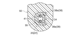
図7(a)、図7(b)、図8及び図9に示すように、ホルダ30は、第1ホルダ部30aと、第2ホルダ部30bとを有する。第1ホルダ部30aは、ホールIC10を保持するセンサ保持部31と、ケーブル40のワイヤ41を保持する半割れの第1ワイヤ保持部33と、ケーブル40を保持する半割れの第1ケーブル保持部35とを備えられている。センサ保持部31と第1ワイヤ保持部33との間には第1接続部32が設けられており、第1ワイヤ保持部33と第1ケーブル保持部35との間には第2接続部34が設けられている。ホールIC10にはケーブル40のワイヤ41が電気的に接続される。センサ保持部31の外面であってケース20の背面部27に対向する位置には、変形可能な当接部36が備えられている。
As shown in FIGS. 7A, 7B, 8, and 9, the
ホルダ30に設けられた当接部36は、ホルダ30のケース20への挿入方向に沿うよう延出されて形成された凸部である。ホルダ30をケース20内に挿入する際に当該凸部(当接部)36がホルダ30を検出面21の側に押圧しつつ案内するように働く。これにより、ケース20内へのホルダ30の挿入が容易となる。
The
第2ホルダ部30bは、半割れの第2ワイヤ保持部37、半割れの第2ケーブル保持部39と、を備える。第2ワイヤ保持部37と第2ケーブル保持部39との間には、第2接続部34に向けて突出して形成された爪部38a、38aを有する第3接続部38が設けられている。爪部38a、38aが第1ホルダ部30aの第2接続部34にスナップフィットされることでホルダ30が構成され、ワイヤ41が当該ホルダ30に保持される。
The
図7(b)に示すように、回転検出センサ1は、第1ホルダ部30aのセンサ保持部31にセンサ素子10が装着された状態で、ケース20内にホルダ30のセンサ保持部31が挿入配置されて構成される。センサ素子10はホルダ30によってケース20の検出面21(前面部26の外面)側に押し付けられ位置決めされる。
As shown in FIG. 7B, the
センサ素子10が装着されたセンサ保持部31の端部の幅Aはケース20の端部のセンサ素子10が配置される部分の幅Bよりも大きい。このため、ケース20へのホルダ30の挿入に際し、背面部27に形成された凸面部29とホルダ30の当接部36とが接触する。当接部36は、センサ素子10が検出面21の側に押圧された際の押圧力によって変形可能に構成されている。したがって、当接部36は、センサ素子10がホルダ30によって押圧された際に検出面21から受ける反力によって変形する。このように、当接部36が変形することで、センサ素子10への押圧力が適正に軽減しつつセンサ素子10を検出面21に保持することができる。その結果、センサ素子10は、収容されるケース20に樹脂を注入することなく、確実に検出面21の側に位置決めすることができる。
The width A of the end portion of the
ケース20内のセンサ素子収容部24にホルダ30のセンサ保持部31が挿入配置されると、ケース20の挿入開口はホルダ30の円筒状部分である、ワイヤ保持部33,37及び接続部34,38によって塞がれる。すなわち、ホルダ30はケース20の挿入開口を塞ぐ蓋部として、ワイヤ保持部33,39及び接続部34,38を備えている。
When the
ケース20、ホルダ30及びケーブル40が金型内に配置され、金型に樹脂が流し込まれることで、モールド成形部50が形成される。ホルダ30にはケース20の挿入開口を塞ぐ蓋部(ワイヤ保持部33,37及び接続部34,38)を備えてあるので、モールド成形部50を樹脂成形する際に、当該蓋部(ワイヤ保持部33,37及び接続部34,38)によってケース20内への樹脂の侵入が阻止される。これにより、センサ素子10に対する成形樹脂の圧力や熱の影響を抑制することができる。また、ケース20内への樹脂の侵入が阻止されることで、ケース20のセンサ素子収容部24が樹脂によって膨れる不具合も防止される。
The
ケース20及びケーブル40の外面は樹脂で構成されている。モールド成形部50が樹脂成形される際に、ケース20及びケーブル40とモールド成形部50とは、それぞれが接し合う樹脂部の溶融により接着される。これにより、ケース20及びケーブル40に接着材料を塗布する工程が不要となり、センサ1を簡易に製造することができる。
The outer surfaces of the
センサ1は、ケース20が袋状に形成され、ケース20のセンサ素子収容部24の対向内面(前面部26及び背面部27)どうしの間にセンサ素子10とホルダ30とが挟持されている。したがって、センサ素子10とホルダ30とをセンサ素子収容部24に挿入配置するだけで、ホルダ30がセンサ素子10を検出面21の側に押圧することとなる。その結果、センサ素子10の検出面21への位置合わせ及び位置保持が容易となる。
In the
[第2実施形態]
図10及び図11に示すように、本実施形態の回転検出センサ1は、センサ素子10がケース20の底部28に配置されている。この回転検出センサ1は、例えば、車両の車輪、エンジン、変速機等の出力側と連動して回転するギア部材(磁性金属材料等)に対して対向配置される。車両駆動時のギア部材の磁界の変化をセンサ素子10が検出することで、例えば車輪の速度やエンジン、変速機等の回転数を検出することができる。
[Second Embodiment]
As shown in FIGS. 10 and 11, in the
回転検出センサ1は、センサ素子10と、センサ素子10が内装されるケース20と、ケース20の内部にセンサ素子10と共に内装されるホルダ60と、センサ素子10に電気的に接続されるケーブル40とを備える。ケース20は外面にセンサ素子10の検出面21を有する。ホルダ60は検出面21の側にセンサ素子10を押圧するよう配置されている。
The
図12(a)及び図12(b)に示すように、ケース20は、円柱状の外形であって上下に開口を有する円筒部22と下方に連設される有底のセンサ素子収容部24とによって構成されている。センサ素子収容部24は外形が円柱状であって外周面に面取りされた平面部24aが形成されている。センサ素子10の検出面21はケース20の底部28に設けられている。ホルダ60には、半割れの第1ホルダ部60aと半割れの第2ホルダ部60bとが接合されて構成されており、長手方向の中間位置に鍔部61が設けられている。
ホルダ60においてケース20に挿入される側には、センサ素子10を挟持する第1脚部62及び第2脚部63が対向配置されている。また、ホルダ60の第1脚部62及び第2脚部63の間の位置にセンサ素子10に当接し変形可能な当接部64が備えられており、当接部64は十字状に形成されセンサ素子10に向けて突出している。
As shown in FIGS. 12A and 12B, the
On the side of the
センサ素子10をホルダ60の第1脚部62及び第2脚部63によって挟持することで、センサ素子10をホルダ60に装着する。その後、ケース20内にホルダ60の先端側を挿入することで、センサ素子10がケース20内に挿入配置される。センサ素子10は、ホルダ60によって当接部64に当接した状態でケース20の底部28の検出面21に向けてセンサ素子10が押圧される。当接部64は、センサ素子10がホルダ60によって押圧された際に検出面21から受ける反力によって変形する。当接部64が変形することで、センサ素子10への押圧力が適正に軽減された状態でセンサ素子10は検出面21に接した状態で保持される。
The
センサ素子10を挟持するホルダ60の第1脚部62及び第2脚部63はケース20の内面における対向位置に接触するよう構成されている。第2脚部63の外面にはホルダ60のケース20への挿入方向に沿うよう延出された変形可能な凸部66が形成されている。ホルダ60をケース20内に挿入する際に当該凸部66がホルダ60を案内するように働く。また、第1脚部62及び第2脚部63によって、ケース20内の水平方向(検出面21に平行な方向)におけるセンサ素子10のがたつきも抑制される。
The
[その他の実施形態]
(1)上記の第1実施形態では、当接部36をホルダ30の外面に形成する例を示したが、当接部36はケース20の内面に形成してもよい。ただ、当接部36をケースに形成する場合には、ケース20の内面に当接部36を形成することとなる。センサ素子10が配置されるケース20は細長い形状である場合があり、そうした場合にはケース20の内面には当接部36を形成し難い。ホルダ20の外面に形成される当接部36は、樹脂成形される際に金型によって形成可能な部位であり多様な形状の当接部36の形成が可能である。
[Other embodiments]
(1) In the first embodiment, the
(2)上記の第2実施形態では、センサ素子10に対向するホルダ60の当接部64を十字状に形成するする例を示したが、当接部64は面状に形成されていてもよい。
(2) In the second embodiment, the
本発明に係るセンサは、各種センサに広く利用可能である。 The sensor according to the present invention can be widely used for various sensors.
1 回転検出センサ(センサ)
10 センサ素子
20 ケース
21 検出面
30 ホルダ
30a 第1ホルダ部
30b 第2ホルダ部
33 第1ワイヤ保持部(蓋部)
34 第2接続部(蓋部)
36 当接部
37 第2ワイヤ保持部(蓋部)
38 第3接続部(蓋部)
40 ケーブル
50 モールド成形部
60 ホルダ
61 鍔部(蓋部)
64 当接部
1 Rotation detection sensor (sensor)
DESCRIPTION OF
34 Second connection part (lid part)
36
38 3rd connection part (lid part)
40
64 Contact part
Claims (5)
前記センサ素子が内装され、外面に前記センサ素子の検出面を有するケースと、
前記センサ素子を嵌入して保持するセンサ保持部と、前記センサ素子に電気的に接続されるケーブルを保持するケーブル保持部と、前記ケースの挿入開口を塞ぐ蓋部と、を有し、前記検出面の側に前記センサ保持部に保持された状態の前記センサ素子を押圧するホルダと、を備え、
前記ホルダ及び前記ケースのうち少なくとも何れか一方に、前記センサ素子が前記検出面の側に押圧された際の押圧力によって変形可能な当接部を設け、
前記ケースと前記ケーブルとを、樹脂を用いたモールド成形部によって一体化してあり、
前記当接部が前記ホルダと前記ケースとが対向する位置に設けられ、前記当接部と前記ホルダ及び前記ケースの一方とが当接するセンサ。 A sensor element;
A case in which the sensor element is internally provided and has a detection surface of the sensor element on an outer surface;
A sensor holding part for inserting and holding the sensor element; a cable holding part for holding a cable electrically connected to the sensor element; and a lid part for closing the insertion opening of the case; A holder for pressing the sensor element in a state of being held by the sensor holding part on the surface side,
At least one of the holder and the case is provided with a contact portion that can be deformed by a pressing force when the sensor element is pressed to the detection surface side,
And said and said casing cable, Ri and integrated by molding portion using a resin tare,
The contact portion between the holder and the casing is provided at a position facing, while the sensors you contact the contact part the holder and the casing.
Priority Applications (5)
| Application Number | Priority Date | Filing Date | Title |
|---|---|---|---|
| JP2012011369A JP6015008B2 (en) | 2012-01-23 | 2012-01-23 | Sensor |
| US14/360,478 US9618315B2 (en) | 2012-01-23 | 2013-01-10 | Sensor |
| PCT/JP2013/050316 WO2013111619A1 (en) | 2012-01-23 | 2013-01-10 | Sensor |
| BR112014016224A BR112014016224A8 (en) | 2012-01-23 | 2013-01-10 | sensor |
| CN201390000219.0U CN204115745U (en) | 2012-01-23 | 2013-01-10 | Sensor |
Applications Claiming Priority (1)
| Application Number | Priority Date | Filing Date | Title |
|---|---|---|---|
| JP2012011369A JP6015008B2 (en) | 2012-01-23 | 2012-01-23 | Sensor |
Publications (3)
| Publication Number | Publication Date |
|---|---|
| JP2013148556A JP2013148556A (en) | 2013-08-01 |
| JP2013148556A5 JP2013148556A5 (en) | 2014-04-03 |
| JP6015008B2 true JP6015008B2 (en) | 2016-10-26 |
Family
ID=48873341
Family Applications (1)
| Application Number | Title | Priority Date | Filing Date |
|---|---|---|---|
| JP2012011369A Expired - Fee Related JP6015008B2 (en) | 2012-01-23 | 2012-01-23 | Sensor |
Country Status (5)
| Country | Link |
|---|---|
| US (1) | US9618315B2 (en) |
| JP (1) | JP6015008B2 (en) |
| CN (1) | CN204115745U (en) |
| BR (1) | BR112014016224A8 (en) |
| WO (1) | WO2013111619A1 (en) |
Families Citing this family (7)
| Publication number | Priority date | Publication date | Assignee | Title |
|---|---|---|---|---|
| CN103528824B (en) * | 2013-10-31 | 2015-09-30 | 华中科技大学 | Based on the inner-outer birotor fault simulation experiment table of elastic foundation |
| JP6403088B2 (en) * | 2014-06-17 | 2018-10-10 | 日立金属株式会社 | Molded resin cable |
| DE102014013356A1 (en) * | 2014-09-08 | 2016-03-10 | Wabco Gmbh | Support for a sensor element, component group and speed sensor |
| DE102014013312A1 (en) * | 2014-09-08 | 2016-03-10 | Wabco Gmbh | Support for a sensor element, component group and speed sensor |
| JP6281461B2 (en) * | 2014-09-30 | 2018-02-21 | 日立金属株式会社 | Manufacturing method of cable with resin mold |
| JP6838306B2 (en) * | 2016-07-08 | 2021-03-03 | 日立金属株式会社 | In-vehicle detection device |
| JP2021156730A (en) * | 2020-03-27 | 2021-10-07 | 日立金属株式会社 | Temperature detector and wire component |
Family Cites Families (13)
| Publication number | Priority date | Publication date | Assignee | Title |
|---|---|---|---|---|
| JP3056674B2 (en) * | 1995-10-12 | 2000-06-26 | 株式会社三協精機製作所 | Rotation detection device |
| JPH11120830A (en) * | 1997-10-09 | 1999-04-30 | Hitachi Ltd | Flat multi-conductor cable connecting structure |
| JPH11295331A (en) * | 1998-04-10 | 1999-10-29 | Matsushita Electric Ind Co Ltd | Rotation speed sensor or rotation angle sensor |
| JP2000164267A (en) * | 1998-11-27 | 2000-06-16 | Ins:Kk | Method for forming cable connection |
| JP2003198093A (en) * | 2001-12-21 | 2003-07-11 | Aisin Seiki Co Ltd | Electronic circuit |
| JP2004264213A (en) | 2003-03-03 | 2004-09-24 | Hitachi Unisia Automotive Ltd | Rotation detection device |
| JP5146711B2 (en) | 2003-05-29 | 2013-02-20 | アイシン精機株式会社 | Resin-sealed product manufacturing method and case |
| JP2005227095A (en) * | 2004-02-12 | 2005-08-25 | Sumiden Electronics Kk | Magnetic variable sensor |
| JP2007523336A (en) * | 2004-02-24 | 2007-08-16 | プレットル,ロルフ | Sensor holder and manufacturing method thereof |
| JP4543751B2 (en) * | 2004-05-27 | 2010-09-15 | アイシン精機株式会社 | Rotation sensor |
| JP4661236B2 (en) | 2005-01-28 | 2011-03-30 | アイシン精機株式会社 | Rotation detection sensor |
| JP4640590B2 (en) * | 2005-05-30 | 2011-03-02 | アイシン精機株式会社 | Sensor device |
| JP4716104B2 (en) * | 2005-10-27 | 2011-07-06 | アイシン精機株式会社 | Sensor device |
-
2012
- 2012-01-23 JP JP2012011369A patent/JP6015008B2/en not_active Expired - Fee Related
-
2013
- 2013-01-10 US US14/360,478 patent/US9618315B2/en active Active
- 2013-01-10 CN CN201390000219.0U patent/CN204115745U/en not_active Expired - Lifetime
- 2013-01-10 WO PCT/JP2013/050316 patent/WO2013111619A1/en active Application Filing
- 2013-01-10 BR BR112014016224A patent/BR112014016224A8/en active Search and Examination
Also Published As
| Publication number | Publication date |
|---|---|
| US9618315B2 (en) | 2017-04-11 |
| CN204115745U (en) | 2015-01-21 |
| JP2013148556A (en) | 2013-08-01 |
| WO2013111619A1 (en) | 2013-08-01 |
| BR112014016224A2 (en) | 2017-06-13 |
| BR112014016224A8 (en) | 2017-07-04 |
| US20140320113A1 (en) | 2014-10-30 |
Similar Documents
| Publication | Publication Date | Title |
|---|---|---|
| JP6015008B2 (en) | Sensor | |
| JP2013148556A5 (en) | ||
| EP2626987B1 (en) | Sensing magnet apparatus for motor | |
| WO2014103499A1 (en) | Wheel speed sensor and wire harness | |
| JP5234522B2 (en) | Rotation detecting device and manufacturing method thereof | |
| US20120306484A1 (en) | Magnetic detection apparatus | |
| US10101412B2 (en) | Sensing device and method for manufacturing sensing device | |
| JP2021012166A (en) | Sensor device | |
| JP2021084627A (en) | Torque-angle sensor | |
| US20110273854A1 (en) | Magnetic Field Sensor | |
| EP3023744A1 (en) | Rotation angle detecting device | |
| WO2006080197A1 (en) | Rotation sensor | |
| US10641623B2 (en) | Onboard detector including cable and sensor module including sensor, housing member and molded article | |
| EP1980859A2 (en) | Rotation detector | |
| CN112424577A (en) | Sensing device | |
| JP6704441B2 (en) | Rotation detector | |
| EP4109064A1 (en) | Magnetic detection module, detection device, case assembly, and production method for magnetic detection module | |
| JP2001183385A (en) | Rotation-detecting apparatus | |
| KR102365919B1 (en) | Motor | |
| CN110062887B (en) | Moving body detection device | |
| JP2021025818A (en) | Sensor device and method for manufacturing the same | |
| JP6431466B2 (en) | Rotation detector | |
| JP2021025817A (en) | Sensor device | |
| JP6969355B2 (en) | Rotation angle detector | |
| JP2002228487A (en) | Moving matter detector |
Legal Events
| Date | Code | Title | Description |
|---|---|---|---|
| A521 | Request for written amendment filed |
Free format text: JAPANESE INTERMEDIATE CODE: A523 Effective date: 20140217 |
|
| A621 | Written request for application examination |
Free format text: JAPANESE INTERMEDIATE CODE: A621 Effective date: 20140314 |
|
| A131 | Notification of reasons for refusal |
Free format text: JAPANESE INTERMEDIATE CODE: A131 Effective date: 20150305 |
|
| A521 | Request for written amendment filed |
Free format text: JAPANESE INTERMEDIATE CODE: A523 Effective date: 20150427 |
|
| A131 | Notification of reasons for refusal |
Free format text: JAPANESE INTERMEDIATE CODE: A131 Effective date: 20150730 |
|
| A521 | Request for written amendment filed |
Free format text: JAPANESE INTERMEDIATE CODE: A523 Effective date: 20150928 |
|
| A131 | Notification of reasons for refusal |
Free format text: JAPANESE INTERMEDIATE CODE: A131 Effective date: 20160209 |
|
| A521 | Request for written amendment filed |
Free format text: JAPANESE INTERMEDIATE CODE: A523 Effective date: 20160303 |
|
| TRDD | Decision of grant or rejection written | ||
| A01 | Written decision to grant a patent or to grant a registration (utility model) |
Free format text: JAPANESE INTERMEDIATE CODE: A01 Effective date: 20160830 |
|
| A61 | First payment of annual fees (during grant procedure) |
Free format text: JAPANESE INTERMEDIATE CODE: A61 Effective date: 20160912 |
|
| R151 | Written notification of patent or utility model registration |
Ref document number: 6015008 Country of ref document: JP Free format text: JAPANESE INTERMEDIATE CODE: R151 |
|
| LAPS | Cancellation because of no payment of annual fees |