JP6014359B2 - Ultrasonic atomizer - Google Patents
Ultrasonic atomizer Download PDFInfo
- Publication number
- JP6014359B2 JP6014359B2 JP2012103621A JP2012103621A JP6014359B2 JP 6014359 B2 JP6014359 B2 JP 6014359B2 JP 2012103621 A JP2012103621 A JP 2012103621A JP 2012103621 A JP2012103621 A JP 2012103621A JP 6014359 B2 JP6014359 B2 JP 6014359B2
- Authority
- JP
- Japan
- Prior art keywords
- diaphragm
- liquid
- chemical
- mpa
- ultrasonic atomizer
- Prior art date
- Legal status (The legal status is an assumption and is not a legal conclusion. Google has not performed a legal analysis and makes no representation as to the accuracy of the status listed.)
- Active
Links
Images


Classifications
-
- B—PERFORMING OPERATIONS; TRANSPORTING
- B05—SPRAYING OR ATOMISING IN GENERAL; APPLYING FLUENT MATERIALS TO SURFACES, IN GENERAL
- B05B—SPRAYING APPARATUS; ATOMISING APPARATUS; NOZZLES
- B05B17/00—Apparatus for spraying or atomising liquids or other fluent materials, not covered by the preceding groups
- B05B17/04—Apparatus for spraying or atomising liquids or other fluent materials, not covered by the preceding groups operating with special methods
- B05B17/06—Apparatus for spraying or atomising liquids or other fluent materials, not covered by the preceding groups operating with special methods using ultrasonic or other kinds of vibrations
- B05B17/0607—Apparatus for spraying or atomising liquids or other fluent materials, not covered by the preceding groups operating with special methods using ultrasonic or other kinds of vibrations generated by electrical means, e.g. piezoelectric transducers
- B05B17/0638—Apparatus for spraying or atomising liquids or other fluent materials, not covered by the preceding groups operating with special methods using ultrasonic or other kinds of vibrations generated by electrical means, e.g. piezoelectric transducers spray being produced by discharging the liquid or other fluent material through a plate comprising a plurality of orifices
- B05B17/0646—Vibrating plates, i.e. plates being directly subjected to the vibrations, e.g. having a piezoelectric transducer attached thereto
-
- A—HUMAN NECESSITIES
- A01—AGRICULTURE; FORESTRY; ANIMAL HUSBANDRY; HUNTING; TRAPPING; FISHING
- A01M—CATCHING, TRAPPING OR SCARING OF ANIMALS; APPARATUS FOR THE DESTRUCTION OF NOXIOUS ANIMALS OR NOXIOUS PLANTS
- A01M1/00—Stationary means for catching or killing insects
- A01M1/20—Poisoning, narcotising, or burning insects
- A01M1/2022—Poisoning or narcotising insects by vaporising an insecticide
- A01M1/2027—Poisoning or narcotising insects by vaporising an insecticide without heating
- A01M1/2044—Holders or dispensers for liquid insecticide, e.g. using wicks
- A01M1/205—Holders or dispensers for liquid insecticide, e.g. using wicks using vibrations, e.g. ultrasonic or piezoelectric atomizers
-
- A—HUMAN NECESSITIES
- A61—MEDICAL OR VETERINARY SCIENCE; HYGIENE
- A61L—METHODS OR APPARATUS FOR STERILISING MATERIALS OR OBJECTS IN GENERAL; DISINFECTION, STERILISATION OR DEODORISATION OF AIR; CHEMICAL ASPECTS OF BANDAGES, DRESSINGS, ABSORBENT PADS OR SURGICAL ARTICLES; MATERIALS FOR BANDAGES, DRESSINGS, ABSORBENT PADS OR SURGICAL ARTICLES
- A61L9/00—Disinfection, sterilisation or deodorisation of air
- A61L9/14—Disinfection, sterilisation or deodorisation of air using sprayed or atomised substances including air-liquid contact processes
-
- B—PERFORMING OPERATIONS; TRANSPORTING
- B05—SPRAYING OR ATOMISING IN GENERAL; APPLYING FLUENT MATERIALS TO SURFACES, IN GENERAL
- B05B—SPRAYING APPARATUS; ATOMISING APPARATUS; NOZZLES
- B05B17/00—Apparatus for spraying or atomising liquids or other fluent materials, not covered by the preceding groups
- B05B17/04—Apparatus for spraying or atomising liquids or other fluent materials, not covered by the preceding groups operating with special methods
- B05B17/06—Apparatus for spraying or atomising liquids or other fluent materials, not covered by the preceding groups operating with special methods using ultrasonic or other kinds of vibrations
- B05B17/0607—Apparatus for spraying or atomising liquids or other fluent materials, not covered by the preceding groups operating with special methods using ultrasonic or other kinds of vibrations generated by electrical means, e.g. piezoelectric transducers
- B05B17/0653—Details
- B05B17/0676—Feeding means
- B05B17/0684—Wicks or the like
-
- A—HUMAN NECESSITIES
- A61—MEDICAL OR VETERINARY SCIENCE; HYGIENE
- A61L—METHODS OR APPARATUS FOR STERILISING MATERIALS OR OBJECTS IN GENERAL; DISINFECTION, STERILISATION OR DEODORISATION OF AIR; CHEMICAL ASPECTS OF BANDAGES, DRESSINGS, ABSORBENT PADS OR SURGICAL ARTICLES; MATERIALS FOR BANDAGES, DRESSINGS, ABSORBENT PADS OR SURGICAL ARTICLES
- A61L2209/00—Aspects relating to disinfection, sterilisation or deodorisation of air
- A61L2209/10—Apparatus features
- A61L2209/13—Dispensing or storing means for active compounds
- A61L2209/132—Piezo or ultrasonic elements for dispensing
Description
本発明は、薬液を超音波振動によって霧化する超音波霧化装置に関する。 The present invention relates to an ultrasonic atomizer that atomizes a chemical solution by ultrasonic vibration.
有効成分を含有した薬液等の液体を室内又は屋外の空間に噴霧する手段として、超音波霧化装置が知られている。超音波霧化装置は、通電により超音波振動を生じる圧電振動子と、この圧電振動子に固着され、多数の微細孔を有する振動板とを有しており、微細孔に液体を供給し、圧電振動子の振動によって振動板に超音波振動を生じさせることで液体を霧化するように構成されている。 2. Description of the Related Art An ultrasonic atomizer is known as means for spraying a liquid such as a chemical solution containing an active ingredient into an indoor or outdoor space. The ultrasonic atomizer has a piezoelectric vibrator that generates ultrasonic vibration when energized, and a vibration plate that is fixed to the piezoelectric vibrator and has a large number of micropores, supplying liquid to the micropores, The liquid is atomized by generating ultrasonic vibration in the diaphragm by the vibration of the piezoelectric vibrator.
特許文献1の霧化装置は、液体を充填する加圧室と、加圧室に臨む複数個のノズルを設けたノズル板と、ノズル板を付勢し、たわみ振動を励起する電気的振動子とを備え、ノズル板に突起部を設け、その突起部に微細孔を設けている。微細孔は、液体が直接接するとともに、横方向(重力方向に対して垂直な方向)を向いている。これにより、特許文献1の霧化装置は、液体を横方向に噴霧する。
The atomization apparatus of
特許文献2の噴霧器は、液体を噴霧するための振動可能な膜と、膜を振動させる振動部とを備える。膜は、第1湾曲部と、第1湾曲部とは異なる曲率の第2湾曲部とを備え、振動部によって振動させられることで、膜に接する液体を噴霧する。特許文献2の噴霧器は、液体を下方(重力方向)に噴霧する。
The sprayer of
特許文献3の超音波霧化装置は、圧電振動子と振動体とからなる複合体を駆動させることで圧電振動子を振動させ、その振動が振動体に伝播する。保液剤と接触する振動体の下面に供給される液体は、振動体の振動に伴い、振動体に形成された穴を通して霧化される。 The ultrasonic atomizing device of Patent Document 3 vibrates the piezoelectric vibrator by driving a composite composed of the piezoelectric vibrator and the vibrator, and the vibration propagates to the vibrator. The liquid supplied to the lower surface of the vibrating body that comes into contact with the liquid retaining agent is atomized through a hole formed in the vibrating body as the vibrating body vibrates.
特許文献4のピエゾ式噴霧器は、粘度が5mPa・s(20℃)〜30mPa・s(20℃)の薬液を使用している。 The piezo nebulizer of Patent Document 4 uses a chemical solution having a viscosity of 5 mPa · s (20 ° C.) to 30 mPa · s (20 ° C.).
しかしながら、特許文献1〜4の技術には次のような問題がある。
However, the techniques of
すなわち、特許文献1の霧化装置および特許文献2の噴霧器は、液体が振動板に直接接するため、仮に噴霧口を上向きにすると、液体は、残存量が減少するほどに振動板から離れ、装置外部に噴霧されなくなる。また、液体の残存量が減少すると、振動板と液体面との間に気泡が溜まり、装置外部に液体が噴霧されなくなる。
That is, in the atomizer of
さらに、特許文献1の霧化装置は、噴霧口が横向きであるため、残存量が減少するほどに液面が低下する。したがって、特許文献1の噴霧装置では、液面がノズルよりも下位になると装置の外部に液体が噴霧されなくなる。
Furthermore, since the atomization apparatus of
さらに、特許文献2の噴霧器は、液体を下方に向かって噴霧するため、液体を全量噴霧させることは可能であるものの、液重量によって振動板に負荷がかかるため、振動板の劣化が早まるという問題がある。
Furthermore, since the sprayer of
このように、特許文献1の霧化装置および特許文献2の噴霧器はいずれも、液体を安定的かつ持続的に装置の外部に噴霧することがそもそも困難である。
As described above, both the atomization apparatus of
特許文献3の超音波霧化装置は、保液剤に浸透させた液体を、保液剤と接触する振動体を介して上向き(重力と反対方向)に噴霧する。しかしながら、特許文献3の超音波霧化装置は、振動体の中央部が湾曲していることから、十分な噴霧高さを得ることが困難である。このため、噴霧される液体の拡散性を十分に得ることができないため、液体を噴霧することで得られる効果(殺菌、殺虫など)を広範囲に行き渡らせることが困難である。 The ultrasonic atomizer of Patent Document 3 sprays the liquid that has permeated the liquid retaining agent upward (in the direction opposite to gravity) through a vibrating body that contacts the liquid retaining agent. However, in the ultrasonic atomizer of Patent Document 3, it is difficult to obtain a sufficient spray height because the central portion of the vibrating body is curved. For this reason, since the diffusibility of the sprayed liquid cannot be obtained sufficiently, it is difficult to spread the effects (sterilization, insecticide, etc.) obtained by spraying the liquid over a wide range.
また、特許文献4のピエゾ式噴霧器は、5mPa・s(20℃)〜30mPa・s(20℃)の薬液を使用し、かつ、振動子が平坦状であるため、薬液の噴霧量、噴霧の安定性等において十分とは言えない。 Further, the piezo-type sprayer of Patent Document 4 uses a chemical solution of 5 mPa · s (20 ° C.) to 30 mPa · s (20 ° C.) and the vibrator is flat. It cannot be said that stability is sufficient.
本発明は、上記の問題を解決するためになされたものであり、その目的は、噴霧する薬液の拡散性を高めることが可能な超音波霧化装置を提供することにある。 The present invention has been made to solve the above problems, and an object of the present invention is to provide an ultrasonic atomizer capable of enhancing the diffusibility of the chemical liquid to be sprayed.
本発明に係る超音波霧化装置は、上記の課題を解決するために、薬液を霧化噴霧する超音波霧化装置であって、薬液貯留容器から薬液を吸液する吸液芯と、厚さ方向に貫通した多数の微細孔を有し、通電により超音波振動を生じる圧電振動子の振動によって上記薬液を霧化噴霧する振動板とを備え、上記振動板は、上記吸液芯を介して上記薬液が供給される錐台状の凸状部を有し、上記薬液として、少なくとも有機溶剤と有効成分とが混合された、粘度が1.7mPa・s(20℃)〜5.0mPa・s(20℃)の薬液が使用されることを特徴としている。 An ultrasonic atomizing apparatus according to the present invention is an ultrasonic atomizing apparatus that atomizes and sprays a chemical solution in order to solve the above-described problem, and includes a liquid absorption core that absorbs the chemical solution from the chemical solution storage container, and a thickness. A vibration plate that has a number of fine holes penetrating in the vertical direction and that atomizes and sprays the chemical liquid by vibration of a piezoelectric vibrator that generates ultrasonic vibration when energized, and the vibration plate passes through the liquid absorption core. And having a frustum-shaped convex portion to which the chemical solution is supplied, and having a viscosity of 1.7 mPa · s (20 ° C.) to 5.0 mPa · at least an organic solvent and an active ingredient are mixed as the chemical solution. It is characterized in that a chemical solution of s (20 ° C.) is used.
上記の構成によれば、本発明に係る超音波霧化装置は、薬液貯留容器から薬液を吸液する吸液芯を備えている。そのため、吸液芯の一端を薬液貯留容器内の薬液に浸漬させ、吸液芯の他端を上向き(重力と反対方向)に方向付けすることで、振動板の振動によって薬液を上向きに霧化噴霧することが可能である。 According to said structure, the ultrasonic atomizer which concerns on this invention is equipped with the liquid absorption core which absorbs a chemical | medical solution from a chemical | medical solution storage container. Therefore, one end of the liquid absorption core is immersed in the chemical liquid in the chemical liquid storage container, and the other end of the liquid absorption core is directed upward (opposite to gravity), so that the chemical liquid is atomized upward by the vibration of the diaphragm. It is possible to spray.
そして、本発明に係る超音波霧化装置では、振動板が、吸液芯を介して薬液が供給される錐台状の凸状部を有する。これにより、本発明に係る超音波霧化装置は、従来のドーム型、平板型等の振動板を用いた薬液噴霧と比べて、薬液の噴霧高さを高くすることができる。したがって、本発明に係る超音波霧化装置は、自装置周辺への薬液の拡散性を高めることができ、有効成分による効果を広範囲に行き渡らせることができる。 And in the ultrasonic atomizer which concerns on this invention, a diaphragm has a frustum-shaped convex part to which a chemical | medical solution is supplied via a liquid absorption core. Thereby, the ultrasonic atomizer which concerns on this invention can make the spray height of a chemical | medical solution high compared with the chemical | medical solution spray using the diaphragms, such as the conventional dome shape and a flat plate type. Therefore, the ultrasonic atomization apparatus according to the present invention can enhance the diffusibility of the chemical solution around the apparatus itself, and can spread the effect of the active ingredient over a wide range.
さらに、本発明に係る超音波霧化装置では、薬液として、少なくとも有機溶剤と有効成分とが混合された、粘度が1.7mPa・s(20℃)〜5.0mPa・s(20℃)の薬液が使用される。これにより、本発明に係る超音波霧化装置は、有機溶剤による自然蒸散性によって薬液の拡散性を高めるとともに、錐台状の凸状部を有する振動板と上記の薬液の粘度範囲との組み合わせによって、さらに、薬液の噴霧量や噴霧高さなどを向上させて、薬液の拡散性を高めることができる。 Furthermore, in the ultrasonic atomizer according to the present invention, as a chemical solution, at least an organic solvent and an active ingredient are mixed, and the viscosity is 1.7 mPa · s (20 ° C.) to 5.0 mPa · s (20 ° C.). A chemical is used. As a result, the ultrasonic atomizer according to the present invention increases the diffusibility of the chemical liquid by natural transpiration due to the organic solvent, and the combination of the diaphragm having the frustum-shaped convex portion and the viscosity range of the chemical liquid. Further, the diffusibility of the chemical solution can be improved by improving the spray amount and the spray height of the chemical solution.
また、本発明に係る超音波霧化装置では、上記薬液は、さらに、粘度が1.7mPa・s(20℃)〜4.0mPa・s(20℃)であってもよい。 In the ultrasonic atomizer according to the present invention, the chemical solution may further have a viscosity of 1.7 mPa · s (20 ° C.) to 4.0 mPa · s (20 ° C.).
粘度が1.7mPa・s(20℃)〜4.0mPa・s(20℃)であることにより、薬液の噴霧量がさらに多くなり、かつ、噴霧の安定性を良好に保つことができる。 When the viscosity is 1.7 mPa · s (20 ° C.) to 4.0 mPa · s (20 ° C.), the spray amount of the chemical solution is further increased, and the spray stability can be kept good.
また、本発明に係る超音波霧化装置では、上記振動板は、上記微細孔が上記凸状部の上底にのみ形成されている構成であってもよい。 In the ultrasonic atomizer according to the present invention, the diaphragm may have a configuration in which the fine holes are formed only on the upper bottom of the convex portion.
上記の構成によれば、本発明に係る超音波霧化装置は、さらに、液体の噴霧高さを高くし、かつ、振動板の耐久性を高めることができる。 According to said structure, the ultrasonic atomizer which concerns on this invention can raise the spray height of a liquid further, and can improve the durability of a diaphragm.
また、本発明に係る超音波霧化装置では、上記振動板は、当該振動板の全体に上記微細孔が形成されている構成であってもよい。 In the ultrasonic atomizer according to the present invention, the diaphragm may have a configuration in which the fine holes are formed in the entire diaphragm.
上記の構成によれば、本発明に係る超音波霧化装置は、ドーム型等の振動板を用いる従来の超音波霧化装置よりも振動板の耐久性を高めることができる。 According to said structure, the ultrasonic atomizer which concerns on this invention can improve durability of a diaphragm rather than the conventional ultrasonic atomizer which uses diaphragms, such as a dome shape.
また、本発明に係る超音波霧化装置では、上記振動板は、上記凸状部が円錐台状であってもよい。 In the ultrasonic atomizer according to the present invention, the convex portion of the diaphragm may have a truncated cone shape.
また、本発明に係る超音波霧化装置では、上記振動板は、上記凸状部が角錐台状であってもよい。 In the ultrasonic atomizer according to the present invention, the convex portion of the diaphragm may have a truncated pyramid shape.
本発明に係る超音波霧化装置では、上記振動板は、上記凸状部が円錐台状または角錐台状であってもよい。 In the ultrasonic atomizer according to the present invention, the diaphragm may have a truncated cone shape or a truncated pyramid shape.
したがって、装置ごとに、装置のレイアウトや吸液芯の形状に適合するように、振動板の凸状部の形状を円錐台状または角錐台状に変更することができ、装置設計を柔軟に変更することができる。 Therefore, the shape of the convex part of the diaphragm can be changed to a truncated cone shape or a truncated pyramid shape so as to suit the layout of the device and the shape of the liquid absorption core for each device, and the device design can be flexibly changed. can do.
また、本発明に係る超音波霧化装置では、上記薬液貯留容器は、上記超音波霧化装置に着脱自在に収容され、上記吸液芯が吸液した上記薬液を上記振動板に供給する吸収体を備え、上記吸収体は、上記薬液貯留容器が上記超音波霧化装置に着脱されるときに、上記薬液貯留容器とともに上記超音波霧化装置に着脱される構成であってもよい。 In the ultrasonic atomizing device according to the present invention, the chemical liquid storage container is detachably accommodated in the ultrasonic atomizing device, and the chemical liquid absorbed by the liquid absorption core is supplied to the diaphragm. The absorbent body may be configured to be attached to and detached from the ultrasonic atomizer together with the chemical liquid storage container when the chemical liquid storage container is attached to and detached from the ultrasonic atomizer.
上記の構成によれば、超音波霧化装置から薬液貯留容器を取り出すとき、吸収体は、薬液貯留容器とともに装置の外部に取り出されるため、超音波霧化装置側に残ることはない。このため、薬液貯留容器中に薬液がなくなり吸収体が乾燥したとき、薬液貯留容器を交換する際には吸収体ごと交換されるため、超音波霧化装置を再稼動したときに吸収体に由来する繊維等によって振動板の微細孔が閉塞することを抑制できる。この効果は、特に、振動板が装置本体側に固定されているときに発揮される。 According to said structure, when taking out a chemical | medical solution storage container from an ultrasonic atomizer, since an absorber is taken out of the apparatus with a chemical | medical solution storage container, it does not remain on the ultrasonic atomizer side. For this reason, when there is no chemical in the chemical storage container and the absorber is dried, the entire absorbent is replaced when the chemical storage container is replaced. It can suppress that the fine hole of a diaphragm is obstruct | occluded with the fiber etc. which do. This effect is particularly exerted when the diaphragm is fixed to the apparatus main body side.
これにより、本発明に係る超音波霧化装置は、上記閉塞が理由で、薬液の噴霧量を不安定にさせることも、また、高いコストを要する振動板の交換をユーザに強いることも軽減することができる。 As a result, the ultrasonic atomization apparatus according to the present invention reduces the amount of spraying the chemical liquid unstable due to the above-mentioned blockage, and also forcing the user to replace the vibration plate requiring high cost. be able to.
このように、本発明に係る超音波霧化装置は、振動板の微細孔を閉塞させることを抑制することで、超音波霧化装置の噴霧安定性を向上させることができ、さらに、コスト面においてもユーザ負担を軽減することができる。 As described above, the ultrasonic atomization device according to the present invention can improve the spray stability of the ultrasonic atomization device by suppressing the clogging of the micropores of the diaphragm, and further reduce the cost. The user burden can be reduced.
本発明に係る超音波霧化装置は、上記の課題を解決するために、液体を霧化噴霧する超音波霧化装置であって、霧化すべき液体を吸液する吸液芯と、平面視リング状であって、通電により径方向に超音波振動を生じる圧電振動子と、この圧電振動子の中央開口を塞ぐように上記圧電振動子に固着された振動板とを備え、上記振動板は、上記圧電振動子の中央開口の中心と中心が略一致し、噴霧方向に突出した円錐台状の凸状部を有するとともに、少なくとも上記凸状部の上底には、厚さ方向に貫通した多数の微細孔を有し、上記吸液芯を介して上記振動板に上記液体を供給することを特徴としている。 An ultrasonic atomizing apparatus according to the present invention is an ultrasonic atomizing apparatus that atomizes and sprays a liquid in order to solve the above-described problem, and includes a liquid absorption core that absorbs the liquid to be atomized and a plan view. A ring-shaped piezoelectric vibrator that generates ultrasonic vibration in a radial direction when energized, and a diaphragm fixed to the piezoelectric vibrator so as to close a central opening of the piezoelectric vibrator, The center of the opening of the piezoelectric vibrator substantially coincides with the center of the piezoelectric vibrator and has a frustoconical convex portion protruding in the spraying direction, and at least the upper base of the convex portion penetrates in the thickness direction. It has a large number of fine holes, and is characterized in that the liquid is supplied to the diaphragm via the liquid absorption core.
上記の構成によれば、本発明に係る超音波霧化装置は、振動板が、吸液芯を介して液体が供給される円錐台状の凸状部を有する。これにより、本発明に係る超音波霧化装置は、従来のドーム型等の振動板を用いた液体噴霧と比べて、液体の噴霧高さを高くすることができる。したがって、本発明に係る超音波霧化装置は、自装置周辺への液体の拡散性を高めることができ、例えば液体が殺虫剤である場合などに、殺虫効果を広範囲に行き渡らせることができる。 According to the above configuration, in the ultrasonic atomizer according to the present invention, the vibration plate has the truncated cone-shaped convex portion to which the liquid is supplied via the liquid absorption core. Thereby, the ultrasonic atomizer which concerns on this invention can make the spray height of a liquid high compared with the liquid spray using the diaphragms, such as the conventional dome shape. Therefore, the ultrasonic atomization apparatus according to the present invention can increase the diffusibility of the liquid around the apparatus itself, and can spread the insecticidal effect over a wide range, for example, when the liquid is an insecticide.
さらに、本発明に係る超音波霧化装置は、振動板が円錐台状の凸状部を有することで、従来の振動板よりも耐久性を高めることができる。したがって、本発明に係る超音波霧化装置は、振動板の交換という手間、および交換費用など、ユーザへの負担を軽減することができる。 Furthermore, the ultrasonic atomizer which concerns on this invention can improve durability rather than the conventional diaphragm because a diaphragm has a truncated cone-shaped convex part. Therefore, the ultrasonic atomization apparatus according to the present invention can reduce the burden on the user such as the trouble of replacing the diaphragm and the replacement cost.
また、本発明に係る超音波霧化装置は、上記凸状部の立ち上がり部は、上記圧電振動子の内周面直近に設けられている構成であってもよい。 Further, the ultrasonic atomizer according to the present invention may be configured such that the rising portion of the convex portion is provided in the vicinity of the inner peripheral surface of the piezoelectric vibrator.
本発明に係る超音波霧化装置は、以上のように、薬液貯留容器から薬液を吸液する吸液芯と、厚さ方向に貫通した多数の微細孔を有し、通電により超音波振動を生じる圧電振動子の振動によって上記薬液を霧化噴霧する振動板とを備え、上記振動板は、上記吸液芯を介して上記薬液が供給される錐台状の凸状部を有し、上記薬液として、少なくとも有機溶剤と有効成分とが混合された、粘度が1.7mPa・s(20℃)〜5.0mPa・s(20℃)の薬液が使用される構成である。 As described above, the ultrasonic atomizer according to the present invention has a liquid absorption core that absorbs a chemical solution from the chemical solution storage container and a large number of fine holes penetrating in the thickness direction. A vibration plate that atomizes and sprays the chemical liquid by the vibration of the generated piezoelectric vibrator, and the vibration plate has a frustum-shaped convex portion to which the chemical liquid is supplied through the liquid absorption core. As the chemical solution, a chemical solution having a viscosity of 1.7 mPa · s (20 ° C.) to 5.0 mPa · s (20 ° C.) in which at least an organic solvent and an active ingredient are mixed is used.
また、本発明に係る超音波霧化装置は、以上のように、霧化すべき液体を吸液する吸液芯と、平面視リング状であって、通電により径方向に超音波振動を生じる圧電振動子と、この圧電振動子の中央開口を塞ぐように上記圧電振動子に固着された振動板とを備え、上記振動板は、上記圧電振動子の中央開口の中心と略中心が一致し、噴霧方向に突出した円錐台状の凸状部を有するとともに、少なくとも上記凸状部の上底には、厚さ方向に貫通した多数の微細孔を有し、上記吸液芯を介して上記振動板に上記液体を供給する構成である。 Further, as described above, the ultrasonic atomizing device according to the present invention includes a liquid absorption core that absorbs the liquid to be atomized and a ring shape in plan view, and a piezoelectric device that generates ultrasonic vibrations in the radial direction when energized. A vibrator and a diaphragm fixed to the piezoelectric vibrator so as to close the central opening of the piezoelectric vibrator, and the diaphragm is substantially coincident with the center of the central opening of the piezoelectric vibrator; It has a frustoconical convex part protruding in the spraying direction, and has a number of fine holes penetrating in the thickness direction at least on the upper base of the convex part, and the vibration through the liquid absorption core. The liquid is supplied to the plate.
それゆえ、本発明に係る超音波霧化装置は、噴霧する薬液の拡散性を高めることが可能となる。 Therefore, the ultrasonic atomizer according to the present invention can enhance the diffusibility of the chemical liquid to be sprayed.
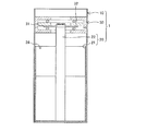
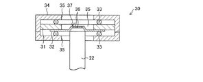
まず、本実施の形態に係る超音波霧化装置1について図1等を参照しながら説明する。図1は、超音波霧化装置1の概略図である。図2は、超音波霧化装置1の霧化部30の拡大図である。
(超音波霧化装置1について)
超音波霧化装置1は、薬液を超音波振動によって霧化する装置であって、霧化部30を有する装置本体10と、装置本体10に収容される薬液容器(薬液貯留容器)20とを備える。薬液は、殺虫剤、殺菌剤、芳香等を目的とするものが用いられる。
First, the
(About the ultrasonic atomizer 1)
The
(装置本体10)
装置本体10は、薬液容器20を収容するとともに、霧化部30を備える。薬液容器20は、装置本体10に着脱自在に収容されてよい。霧化部30は、図2に示すように、通電によって超音波振動を生じる圧電振動子31と、圧電振動子31の振動によって薬液を霧化する振動板32と、圧電振動子31の上面及び振動板32の下面にそれぞれに添わせた円環状の弾性部材としての一対の弾性リング33と、この一対の弾性リング33を介して圧電振動子31及び振動板32を弾性的に挟み込んで保持するケーシング34とを備える。
(Device main body 10)
The apparatus
圧電振動子31は、中央部に開口部35が形成された円形薄板状の圧電セラミックスによって構成されている。この圧電振動子31は、厚さ方向に分極されており、両面に形成された電極(図示せず)に高周波電圧を印加することにより、径方向への超音波振動を生じる。圧電振動子31は、例えば、厚さが0.1mm〜4.0mm、外径が6mm〜60mmであり、発振周波数が30kHz〜500kHzである圧電振動子であればよい。
The
振動板32は、例えばニッケル、ニッケル合金、又は鉄合金からなる円形の薄板である。振動板32は、圧電振動子31の開口部35を覆った状態で、図1において圧電振動子31の下面に対して圧電振動子31と同心に接合(固着)されている。この振動板32は、例えば、厚さが0.02mm〜2.0mm、外径が6mm〜60mmである。振動板32の外径は、圧電振動子31の開口部35の内径寸法より大きくなるように、圧電振動子31の大きさに応じて適宜選択される。
The
振動板32における圧電振動子31の開口部35に臨む部分には、厚さ方向に貫通した多数の微細孔36が形成されている。微細孔36の孔径は、直径3μm〜150μmであるのが好ましい。振動板については、図3等を参照して後述する。
A large number of
なお、図1、図2等では、振動板32の凸状部37の上底にのみ微細孔36が形成されている。しかしながら、本実施の形態に係る振動板は、振動板の全面に微細孔36が形成されていてもよい。
In FIG. 1, FIG. 2, etc., the
超音波霧化装置1では、吸液芯22(後述)を介して微細孔36に薬液が供給され、通電により圧電振動子31が超音波振動を生じ、その圧電振動子の振動によって振動板32に生じた超音波振動により薬液が霧化される。
In the
弾性リング33は一対設けられている。かかる一対の弾性リング33は、ケーシング34と圧電振動子31の上面との間、及びケーシング34と振動板32の下面との間で弾性変形した状態で、それぞれ圧電振動子31及び振動板32と同心状に、上記の上面及び下面に対して接触している。
A pair of
この弾性リング33としては、線径0.5mm〜3mmのOリングが好適に用いられる。また、弾性リング33の硬さは20IRHD〜90IRHDであるのが好ましい。これにより、圧電振動子31及び振動板32を適度な弾力で保持して、圧電振動子31の振動を拘束することなく、圧電振動子31をケーシング34内の所定位置に保持することができる。このため、薬液をより安定的に霧化させることができる。
As this
なお、圧電振動子31の上面に接触させた弾性リング33と、振動板32の下面に接触させた弾性リング33とは、平均径[(内径+外径)/2]、線径、硬さ等が同一のものが好ましく、特に平均径については同じものがよい。
Note that the
弾性リング33の素材としては、ニトリルゴム、フッ素ゴム、エチレンプロピレンゴム、シリコーンゴム、アクリルゴム、水素化ニトリルゴム等が挙げられる。
Examples of the material of the
弾性リング33は、前記Oリングに代えて、断面形状が楕円、四角形、三角形あるいは菱形等のリングであってもよく、また、D字型、X字型、T字型等のリングであってもよい。また、この弾性リング33は、周方向に完全につながって連続している必要はなく、周方向に一箇所切れ目が入っていてもよく、周方向に数箇所間欠的に切れ目が入っていてもよい。
The
また、円形薄板状の振動板32が圧電振動子31の開口部35を完全に覆うものを例示したが、矩形薄板状の振動板を用い、この振動板を圧電振動子31の開口部35を跨ぐように掛け渡し、振動板の両端部を圧電振動子31の一方の面に固着するようにしてもよい。
Further, although the circular thin plate-
なお、霧化部30は、上記の構造のものの他に、公知のピエゾ噴霧部を用いてもよく、適宜選択されうる。
In addition, the
(薬液容器20)
薬液容器20は、容器本体21と、吸液芯22とを備え、装置本体10に着脱自在に収容される。
(Chemical solution container 20)
The chemical
容器本体21は、例えば、上部に開口部24を有する有底円筒状の容器から構成されている。容器本体21には薬液が入れられている。容器本体21の素材としては、ガラスや合成樹脂等が挙げられる。
The container
吸液芯22は、例えば不織布からなる直径が2mm〜6mmの円柱状のものである。吸液芯22の下部側は、容器本体21内の薬液に浸漬されており、薬液を毛細管現象によって吸液芯22の上部側に供給することができる。
The
吸液芯22は、円柱状のみならず、角柱状であってもよく、その形状は任意である。また、吸液芯22の太さは、圧電振動子31の開口部35、もしくは、振動板32の凸状部37の内部に挿入できる太さであればよい。
The
吸液芯22の材質としては、連通孔を有する多孔質体、連続気泡を有する樹脂体又は樹脂繊維の集合体が好ましいものとして例示できる。具体的には、ポリウレタン、ポリエチレン、ポリエチレンテレフタレート、ポリビニルホルマール、ポリスチレン等からなる連続気泡を有する樹脂体、ポリエチレン、ポリプロピレン、ナイロン等の樹脂微粒子を主成分として打錠焼結させた多孔質体、ポリフッ化エチレン等からなる多孔質体、ポリエステル、ポリプロピレン、ナイロン、アクリル、レーヨン、ウール等からなるフェルト部材、あるいはポリオレフィン繊維、ポリエステル繊維、ナイロン繊維、レーヨン繊維、アクリル繊維、ビニロン繊維、ポリフラール繊維、アラミド繊維等からなる不織布等の樹脂繊維の集合体、セラミック等の無機粉体を主成分として打錠焼結した多孔質の無機粉焼結体が例示できるが、何らこれらに限定されるものではない。また、これらに界面活性剤を処理したものでもよい。
Examples of the material of the liquid
装置本体10への薬液容器20の収容方式は、薬液容器20が装置本体10内に着脱自在に収容され、装置本体10内に薬液容器20を収容した状態で吸液芯22と振動板32の凸状部37(後述)とが近接または接触するような方式であれば特に限定されない。例えば、薬液容器20を横方向から水平に移行させて嵌合させる方式や薬液容器20を横方向からわずかな回転角度をともなって嵌合させる方式などがある。
The
(薬液について)
超音波霧化装置1では、有機溶剤と有効成分とが混合された、粘度が1.7mPa・s(20℃)〜5.0mPa・s(20℃)の薬液が使用される。この薬液は、通常、有効成分を有機溶剤に溶解させることにより得られる。
(About chemicals)
In the
有効成分としては、殺虫、殺菌、芳香等を目的とした成分が挙げられる。例えば、
(1)合成ピレスロイド化合物
アクリナトリン(acrinathrin)、アレスリン(allethrin)、ベータ−シフルトリン(beta−cyfluthrin)、ビフェントリン(bifenthrin)、シクロプロトリン(cycloprothrin)、シフルトリン(cyfluthrin)、シハロトリン(cyhalothrin)、シペルメトリン(cypermethrin)、エンペントリン(empenthrin)、デルタメトリン(deltamethrin)、エスフェンバレレート(esfenvalerate)、エトフェンプロックス(ethofenprox)、フェンプロパトリン(fenpropathrin)、フェンバレレート(fenvalerate)、フルシトリネート(flucythrinate)、フルフェンプロックス(flufenoprox)、フルメトリン(flumethrin)、フルバリネート(fluvalinate)、ハルフェンプロックス(halfenprox)、イミプロトリン(imiprothrin)、ペルメトリン(permethrin)、プラレトリン(prallethrin)、ピレトリン(pyrethrins)、レスメトリン(resmethrin)、シグマ−サイパーメトリン(sigma−cypermethrin)、シラフルオフェン(silafluofen)、テフルトリン(tefluthrin)、トラロメトリン(tralomethrin)、トランスフルトリン(transfluthrin)、テトラメトリン(tetramethrin)、フェノトリン(phenothrin)、シフェノトリン(cyphenothrin)、アルファシペルメトリン(alpha−cypermethrin)、ゼータシペルメトリン(zeta−cypermethrin)、ラムダシハロトリン(lambda−cyhalothrin)、ガンマシハロトリン(gamma−cyhalothrin)、フラメトリン(furamethrin)、タウフルバリネート(tau−fluvalinate)、メトフルトリン(metofluthrin)メパフルスリン、d−テフルスリン、ジメフルスリン、2,3,5,6−テトラフルオロ−4−メチルベンジル=2,2−ジメチル−3−(1−プロペニル)シクロプロパンカルボキシレート、2,3,5,6−テトラフルオロ−4−(メトキシメチル)ベンジル=2,2−ジメチル−3−(2−メチル−1−プロペニル)シクロプロパンカルボキシレート、2,3,5,6−テトラフルオロ−4−(メトキシメチル)ベンジル=2,2,3,3−テトラメチルシクロプロパンカルボキシレート等;
(2)有機リン化合物
アセフェート(acephate)、りん化アルミニウム(Aluminium phosphide)、ブタチオホス(butathiofos)、キャドサホス(cadusafos)、クロルエトキシホス(chlorethoxyfos)、クロルフェンビンホス(ch1orfenvinphos)、クロルピリホス(chlorpyrifos)、クロルピリホスメチル(chlorpyrifos−methyl)、シアノホス(cyanophos:CYAP)、ダイアジノン(diazinon)、DCIP(dichlorodiisopropyl ether)、ジクロフェンチオン(dichlofenthion:ECP)、ジクロルボス(dichlorvos:DDVP)、ジメトエート(dimethoate)、ジメチルビンホス(dimethylvinphos)、ジスルホトン(disulfoton)、EPN、エチオン(ethion)、エトプロホス(ethoprophos)、エトリムホス(etrimfos)、フェンチオン(fenthion:MPP)、フエニトロチオン(fenitrothion:MEP)、ホスチアゼート(fosthiazate)、ホルモチオン(formothion)、りん化水素(Hydrogen phosphide)、イソフェンホス(isofenphos)、イソキサチオン(isoxathion)、マラチオン(malathion)、メスルフェンホス(mesulfenfos)、メチダチオン(methidathion:DMTP)、モノクロトホス(monocrotophos)、ナレッド(naled:BRP)、オキシデプロホス(oxydeprofos:ESP)、パラチオン(parathion)、ホサロン(phosalone)、ホスメット(phosmet:PMP)、ピリミホスメチル(pirimiphos−methy1)、ピリダフェンチオン(pyridafenthion)、キナルホス(quinalphos)、フェントエート(phenthoate:PAP)、プロフェノホス(profenofos)、プロパホス(propaphos)、プロチオホス(prothiofos)、ピラクロホス(pyraclorfos)、サリチオン(salithion)、スルプロホス(sulprofos)、テブピリムホス(tebupirimfos)、テメホス(temephos)、テトラクロルビンホス(tetrach1orvinphos)、テルブホス(terbufos)、チオメトン(thiometon)、トリクロルホン(trichlorphon:DEP)、バミドチオン(vamidothion)、フォレート(phorate)、カズサホス(cadusafos)等;
(3)カーバメート化合物
アラニカルブ(alanycarb)、ベンダイオカルブ(bendiocarb)、ベンフラカルブ(benfuracarb)、BPMC、カルバリル(carbary1)、カルボフラン(carbofuran)、カルボスルファン(carbosulfan)、クロエトカルブ(cloethocarb)、エチオフェンカルブ(ethiofencarb)、フェノブカルブ(fenobucarb)、フェノチオカルブ(fenothiocarb)、フェノキシカルブ(fenoxycarb)、フラチオカルブ(furathiocarb)、イソプロカルブ(isoprocarb:MIPC)、メトルカルブ(metolcarb)、 メソミル(methomyl)、メチオカルブ(methiocarb)、NAC、オキサミル(oxamyl)、ピリミカーブ(pirimicarb)、プロポキスル(propoxur:PHC)、XMC、チオジカルブ(thiodicarb)、 キシリルカルブ(xylylcarb)、アルジカルブ(aldicarb)等;
(4)ネライストキシン化合物
カルタップ(cartap)、ベンスルタップ(bensu1tap)、チオシクラム(thiocyclam)、モノスルタップ(monosultap)、ビスルタップ(bisultap)等;
(5)ネオニコチノイド化合物
イミダクロプリド(imidac1oprid)、ニテンピラム(nitenpyram)、アセタミプリド(acetamiprid)、チアメトキサム(thiamethoxam)、チアクロプリド(thiacloprid)、ジノテフラン(dinotefuran)、クロチアニジン(clothianidin)等;
(6)ベンゾイル尿素化合物
クロルフルアズロン(chlorfluazuron)、ビストリフルロン(bistrifluron)、ジアフェンチウロン(diafenthiuron)、ジフルベンズロン(diflubenzuron)、フルアズロン(fluazuron)、フルシクロクスロン(flucycloxuron)、フルフェノクスロン(flufenoxuron)、ヘキサフルムロン(hexaflumuron)、ルフェヌロン(lufenuron)、ノバルロン(novaluron)、ノビフルムロン(noviflumuron)、テフルベンズロン(teflubenzuron)、トリフルムロン(triflumuron)、トリアズロン(triazuron)等;
(7)フェニルピラゾール化合物
アセトプロール(acetoprole)、エチプロール(ethiprole)、フィプロニル(fiproni1)、バニリプロール(vaniliprole)、ピリプロール(pyriprole)、ピラフルプロール(pyrafluprole)等;
(8)Btトキシン殺虫剤
バチルス・チューリンゲンシス菌由来の生芽胞および産生結晶毒素、並びにそれらの混合物;
(9)ヒドラジン化合物
クロマフェノジド(chromafenozide)、ハロフェノジド(halofenozide)、メトキシフェノジド(methoxyfenozide)、テブフェノジド(tebufenozide)等;
(10)有機塩素化合物
アルドリン(aldrin)、ディルドリン(dieldrin)、ジエノクロル(dienochlor)、エンドスルファン(endosulfan)、メトキシクロル(methoxychlor)等;
(11)天然系殺虫剤
マシン油(machine oil)、硫酸ニコチン(nicotine−sulfate);
(12)その他の殺虫剤
アベルメクチン(avermectin−B)、ブロモプロピレート(bromopropylate)、ブプロフェジン(buprofezin)、クロルフェナピル(chlorphenapyr)、シロマジン(cyromazine)、D−D(1,3−Dichloropropene)、エマメクチンベンゾエート(emamectin−benzoate)、フェナザキン(fenazaquin)、フルピラゾホス(flupyrazofos)、ハイドロプレン(hydroprene)、メトプレン(methoprene)、インドキサカルブ(indoxacarb)、メトキサジアゾン(metoxadiazone)、ミルベマイシンA(milbemycin−A)、ピメトロジン(pymetrozine)、ピリダリル(pyridalyl)、ピリプロキシフェン(pyriproxyfen)、スピノサッド(spinosad)、スルフラミド(sulfluramid)、トルフェンピラド(tolfenpyrad)、トリアゼメイト(triazamate)、フルベンジアミド(flubendiamide)、レピメクチン(lepimectin)、亜ひ酸(Arsenic acid)、ベンクロチアズ(benclothiaz)、石灰窒素(Calcium cyanamide)、石灰硫黄合剤(Calcium polysulfide)、クロルデン(chlordane)、DDT、DSP、フルフェネリウム(flufenerim)、フロニカミド(flonicamid)、フルリムフェン(flurimfen)、ホルメタネート(formetanate)、メタム・アンモニウム(metam−ammonium)、メタム・ナトリウム(metam−sodium)、臭化メチル(Methyl bromide)、オレイン酸カリウム(Potassium oleate)、プロトリフェンビュート(protrifenbute)、スピロメシフェン(spiromesifen)、硫黄(Sulfur)、メタフルミゾン(metaflumizone)、スピロテトラマット(spirotetramat)、ピリフルキナゾン(pyrifluquinazone)、スピネトラム(spinetoram)、クロラントラニリプロール(chlorantraniliprole)、トラロピリル(tralopyril)等;
(13)その他の忌避剤
°N,N−ジエチル−m−トルアミド、リモネン、リナロール、シトロネラール、メントール、メントン、ヒノキチオール、ゲラニオール、ユーカリプトール、インドキサカルブ、カラン−3,4−ジオール、MGK−R−326、MGK−R−874及びBAY−KBR−3023等;
(14)共力剤
°5−〔2−(2−ブトキシエトキシ)エトキシメチル〕−6−プロピル−1,3−ベンゾジオキソール、N−(2−エチルヘキシル)ビシクロ[2.2.1]ヘプト−5−エン−2,3−ジカルボキシイミド、オクタクロロジプロピルエーテル、チオシアノ酢酸イソボルニル、N−(2−エチルへキシル)−1−イソプロピル−4−メチルビシクロ[2.2.2]オクト−5−エン−2,3−ジカルボキシイミド等が挙げられるが、本発明は、かかる例示のみに限定されるものではない。これらのなかでは、揮散しやすく、有害生物の防除に適した成分の観点から、メトフルトリン、プロフルトリン、トランスフルトリン、メパフルスリン、d−テフルメスリン、ジメフルスリンが好ましく、メトフルトリンがより好ましい。また、これらは、単独で用いてもよく、2種以上を混合して用いてもよい。
また、薬液中の有効成分の含有量は、特に制限されず、例えば0.05〜10質量%の濃度である。
Examples of the active ingredient include ingredients for insecticidal, sterilizing, aroma and the like. For example,
(1) Synthetic Pyrethroid Compounds Acrinathrin, Allethrin, Beta-Cyfluthrin, Bifenthrin, Cycloprothrin, Cyfluthrin, Cyfluthrin, Cyfluthrin cypermethrin, empentrin, deltamethrin, esfenvalerate, ethofenprox, fenpropratrin, fenvalerate, fenvalerate fluthytrinate, flufenprox, flumethrin, fluvalinate, halfenprox, imiprothrin, permethrin, p, methrerin, p resmethrin, sigma-cypermethrin, silafluofen, tefluthrin, tralomethrin, transfluthrin, tetramethrin ethrin), phenothrin, cyphenothrin, alpha-cypermethrin, zeta-cypermethrin, lambda cihalothrin (lambda-halothrin) ), Furamethrin, tau-fluvalinate, metofluthrin mepafluthrin, d-tefluthrin, dimefurthrin, 2,3,5,6-tetrafluoro-4-methylbenzyl = 2,2-dimethyl- 3- (1-propenyl) cyclopropanecarboxylate, 2,3,5,6 Tetrafluoro-4- (methoxymethyl) benzyl = 2,2-dimethyl-3- (2-methyl-1-propenyl) cyclopropanecarboxylate, 2,3,5,6-tetrafluoro-4- (methoxymethyl) Benzyl = 2,2,3,3-tetramethylcyclopropanecarboxylate and the like;
(2) Organophosphorus compounds Acephate, aluminum phosphide, butathiofos, cadusafos, chlorethoxyphos, chlorfenbinphos, chloropyrophos, chlorpyriphos Methyl (Chlorpyrifos-methyl), Cyanophos (CYAP), Diazinon, DCIP (Dichlorodipropionether), Dichlorfenthion (ECP), Dichlorvos (DchlorPs: DV) (Dimethoate), dimethylvinphos (dimethylvinphos), disulfoton (disulfoton), EPN, ethione (ethion), etiophos (etrimfos), fenthion (MPP), fenitrothion (fetiothion) ), Formothion, hydrogen phosphide, isofenphos, isoxathion, malathion, mesulfenfos, methidathion: DMTP Rotofos, nared (BRP), oxydeprofos (ESP), parathion, fosarone, phosmet (PMP), pirimiphosmethyl (piripyphos) Quinalphos, phenhoate (PAP), profenofos, propopafos, prothiophos, pyraclorfos, salithion, sulprofos sulprofos pirimfos), temephos (temephos), tetrachlorvinphos bottle phosphite (tetrach1orvinphos), terbufos (terbufos), thiometon (thiometon), trichlorfon (trichlorphon: DEP), vamidothion (vamidothion), folate (phorate), cadusafos (cadusafos), and the like;
(3) Carbamate compounds alaniccarb, bendiocarb, benfuracarb, BPMC, carbaryl (carbary1), carbofuran, carbothofen, loecarb , Fenobucarb, phenothiocarb, phenoxycarb, furathiocarb, isoprocarb (MIPC), methocarb (metolcarb) hiocarb), NAC, oxamyl (oxamyl), pirimicarb (pirimicarb), propoxur (propoxur: PHC), XMC, thiodicarb (thiodicarb), xylylcarb (xylylcarb), aldicarb (aldicarb) or the like;
(4) nereistoxin compound cartap, bensultap, thiocyclam, monosultap, bisultap, etc .;
(5) neonicotinoid compounds imidacloprid (imidac1oprid), nitenpyram (nitenpyram), acetamiprid (acetamipride), thiamethoxam, thiacloprid (thiacloprid), dinoteurin (dinocurin)
(6) Benzoylurea compound Chlorfluazuron, bistrifluron, diafenthiuron, diflubenzuron, fluazuron, flucycloxuron, flucyclolone (Flufenoxuron), hexaflumuron, lufenuron, novaluron, novifluuron, teflubenzuron, trifluzuron, trifluzuron, etc.
(7) Phenylpyrazole compounds Acetoprole, etiprole, fipronil, vaniliprole, pyriprole, pyrafluprole, etc .;
(8) Bt toxin insecticide live spores and produced crystal toxins derived from Bacillus thuringiensis, and mixtures thereof;
(9) Hydrazine compounds Chromafenozide, halofenozide, methoxyphenozide, tebufenozide and the like;
(10) Organochlorine compound Aldrin, dieldrin, dienochlor, endosulfan, methoxychlor, etc .;
(11) Natural insecticide machine oil, nicotine sulfate (nicotine-sulfate);
(12) Other insecticides avermectin (vermectin-B), bromopropyrate, buprofezin, chlorfenapyr, cyromazine, D-D (1, ro-dictin) emamectin-benzoate, fenazaquin, flupyrazofos, hydroprene, methoprene, indoxacarb, methoadiamycin pymetrozine, pyridalyl, pyriproxyfen, spinosad, sulfuramide, tolfenpyrad, triazemate, flubenamide, flubenamide, flubenamide, flubenamide Arsenic acid, Benclothiaz, lime nitrogen (Calcium polysulfide), chlordane, DDT, DSP, flufenerimide, flufenerimide Flurimfen, formatenate, metham-ammonium, metham-sodium, methyl bromide, potassium oleate, prototribute fate ), Spiromesifen, sulfur, metaflumizone, spirotetramat, pyrifluquinazone, spinetoril, chlorantirp rapylil) etc .;
(13) Other repellents ° N, N-diethyl-m-toluamide, limonene, linalool, citronellal, menthol, menthone, hinokitiol, geraniol, eucalyptol, indoxacarb, caran-3,4-diol, MGK- R-326, MGK-R-874, BAY-KBR-3023, etc .;
(14) Synergist ° 5- [2- (2-butoxyethoxy) ethoxymethyl] -6-propyl-1,3-benzodioxole, N- (2-ethylhexyl) bicyclo [2.2.1] Hept-5-ene-2,3-dicarboximide, octachlorodipropyl ether, isobornyl thiocyanoacetate, N- (2-ethylhexyl) -1-isopropyl-4-methylbicyclo [2.2.2] oct Examples include -5-ene-2,3-dicarboximide and the like, but the present invention is not limited to such examples. Among these, from the viewpoint of components that are easily volatilized and are suitable for controlling pests, metfurthrin, profluthrin, transfluthrin, mepafluthrin, d-teflumethrin, and dimefrin are preferable, and metfurthrin is more preferable. Moreover, these may be used independently and may mix and
Moreover, the content of the active ingredient in the chemical solution is not particularly limited, and is, for example, a concentration of 0.05 to 10% by mass.
有機溶剤は、有機溶剤に有効成分を溶解させて得られる薬液の粘度が1.7mPa・s(20℃)〜5.0mPa・s(20℃)となる有機溶剤が用いられる。例えば、n−パラフィン(C12〜C15)(カクタスノルマルパラフィン:JX日鉱日石エネルギー社)、ナフテン系溶剤(Exxsol D110:エクソン・モービル社)等の炭化水素類、ラウリン酸メチル、ヤシ油脂脂肪酸メチル、ミリスチン酸イソプロピル、オレイン酸メチル等のエステル類、2−メチル−1−プロパノール等のアルコール類、プロピレングリコールモノメチルエーテル等のグリコールエーテル類などが挙げられる。また、これらは、単独で用いてもよく、2種以上を混合して用いてもよい。
As the organic solvent, an organic solvent in which the viscosity of a chemical obtained by dissolving an active ingredient in the organic solvent is 1.7 mPa · s (20 ° C.) to 5.0 mPa · s (20 ° C.) is used. For example, hydrocarbons such as n-paraffin (C 12 to C 15 ) (Cactus normal paraffin: JX Nippon Oil & Energy Corporation), naphthenic solvents (Exxsol D110: Exxon Mobil), methyl laurate, coconut oil fatty acid Examples thereof include esters such as methyl, isopropyl myristate, and methyl oleate, alcohols such as 2-methyl-1-propanol, and glycol ethers such as propylene glycol monomethyl ether. Moreover, these may be used independently and may mix and
なお、薬液には、上記の粘度範囲が保たれる範囲で、酸化防止剤や活性剤等が適宜混合されてよい。 In the chemical solution, an antioxidant, an activator, and the like may be appropriately mixed within a range in which the above viscosity range is maintained.
(振動板への薬液の供給の変形例)
振動板32への薬液の供給は、次のように行われてもよく、このことを図4により説明する。図4は、超音波霧化装置1の変形例である。なお、図1等を用いて説明した事項については、その説明を省略する。
(Modification of chemical supply to the diaphragm)
The chemical liquid may be supplied to the
図4に示すように、薬液容器20は、容器本体21と、吸液芯22と、吸収体23とを備え、装置本体10に着脱自在に収容される。
As shown in FIG. 4, the chemical
吸液芯22は、例えば不織布からなる直径が2mm〜6mmの円柱状のものである。吸液芯22の下部側は、容器本体21内の薬液に浸漬されており、薬液を毛細管現象によって吸液芯22の上部側に供給することができる。その吸液芯22の上部側には吸収体23が付設されている。
The
吸収体23は、吸液芯22の上部側において吸液芯22と一体に設けられている。つまり、吸収体23は、薬液容器20が超音波霧化装置1に着脱されるときに、薬液容器20とともに超音波霧化装置1に着脱される。吸収体23は、振動板32の凸状部37に近接又は接触しており、その凸状部37に、吸液芯22が吸液した薬液を供給する。吸収体23の材質は、吸液芯22と同様の材質を用いることができる。
The
なお、本実施の形態では、「一体」は、同一の構造のようになっていること、あるいは、一つにまとまっている状態を含む表現として用いる。 Note that in this embodiment, “integrated” is used as an expression including the same structure or a state of being integrated.
吸液芯22および吸収体23は、容器本体21に固定され、かつ、薬液容器20(または、容器本体21)から着脱可能に取り付けられる。
The
上記の構成によれば、超音波霧化装置1から薬液容器20を取り出すとき、吸収体23は、薬液容器20とともに超音波霧化装置1の外部に取り出され、超音波霧化装置1側には残らない。このため、薬液容器20中に薬液がなくなり吸収体23が乾燥したとき、薬液容器20を交換する際には吸収体23ごと交換されるため、超音波霧化装置1を再稼動したときに吸収体23に由来する繊維等によって振動板32の微細孔が閉塞することを抑制できる。この効果は、特に、振動板32が超音波霧化装置1側に固定されているときに発揮される。
According to said structure, when taking out the chemical |
これにより、超音波霧化装置1は、上記閉塞が理由で、薬液の噴霧量を不安定にさせることも、また、高いコストを要する振動板の交換をユーザに強いることも少なくなる。
As a result, the
但し、吸液芯22および/または吸収体23は、超音波霧化装置1側に固定される構造で実現されてもよい。
However, the
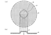
(振動板について)
次に、振動板32の詳細を図3により説明する。図3は、振動板32の概略図であり、図3(a)は上面図を、図3(b)は断面図を示す。
(About the diaphragm)
Next, details of the
上述したように、振動板32は、例えばニッケルからなる円形の薄板からなり、圧電振動子31の下面に対して圧電振動子31と同心に接合(固着)されている。さらに、振動板32は円錐台状の凸状部37を有し、その凸状部37は、その円錐台の中心が圧電振動子31に略同心に形成されている。そして、図3(a)および図3(b)に示すように、凸状部37の上底にのみ、複数の微細孔36が形成されている。
As described above, the
次に、本実施の形態に係る振動板の変形例を図5に示す。図5は、振動板40の概略図であり、図5(a)は上面図を、図5(b)は断面図を示す。
Next, a modification of the diaphragm according to the present embodiment is shown in FIG. 5A and 5B are schematic views of the
振動板40は、振動板32と次の点で相違する。つまり、振動板32は、振動板32の凸状部37の上底にのみ微細孔36が形成されているのに対して、振動板40では、振動板40の全体に微細孔36が形成されている。そして、本実施の形態では、振動板32に加え、振動板40を用いることもできる。
The
次に、本実施の形態に係る振動板の変形例を図6に示す。図6は、振動板45の概略図であり、図6(a)は上面図を、図6(b)は断面図を示す。
Next, a modification of the diaphragm according to the present embodiment is shown in FIG. 6A and 6B are schematic views of the
振動板45は、振動板32と次の点で相違する。つまり、振動板32は、その凸状部37が円錐台状であるのに対して、振動板45では、凸状部37は、8角錐台状で形成されている。そして、本実施の形態では、振動板32等に加え、振動板45を用いることもできる。
The
ここで、図6では、振動板45の凸状部37の上底にのみ形成されている。しかしながら、振動板45は、上記構成のほかに、上底に加え、凸状部37の側面部、または当該側面部を含む振動板45の全体に複数の微細孔36が形成されていてもよい。さらに、上記の説明では、振動板45は8角錐台状であるものとして説明した。しかしながら、振動板45は、4角錐台、16角錐台等のn角錐台状で形成されていてもよい。
Here, in FIG. 6, the
ここで、振動板32、振動板40、および振動板45は、薬液の噴霧方向の断面がいずれも台形であり、また、薬液の噴霧口となる面が平面である点が共通である。ただし、錐台状の振動板32、振動板40、および振動板45の上底および側面は、正確に平らな形状でなくとも、多少の曲率を有する面で形成されていてもよい。
Here, the
また、図3に示す霧化部30においては、振動板32に形成された円錐台状の凸状部37の立ち上がり部が中心方向に寄ったものを例示したが、例えば、図7に示すように、円錐台状の凸状部37の立ち上がり部が圧電振動子31の内周面の直近に設けられた振動板50が用いられてもよい。
Moreover, in the
(効果確認試験1)
次に、超音波霧化装置1により得られる効果を、効果確認試験1の結果を通して説明する。
(Effect confirmation test 1)
Next, the effect obtained by the
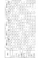
効果確認試験1では、粘度が0.59〜6.12mPa・s(20℃)の範囲である複数の有機溶剤それぞれに対して、平板型(比較例1)、ドーム型(比較例2)、円錘台型(本実施例)の振動子を用いたときの噴霧量等を確認した。試験に用いた有機溶剤は図7に記載されている。図7は、薬液粘度と噴霧量等との関係を示す表であり、図示するように、有機溶剤は、粘度0.59mPa・s(20℃)のエタノールから、粘度6.12mPa・s(20℃)のナフテン+パラフィン(Exxsol D130)までの10種類を用いた。
In the
また、図7に示すように、効果確認試験1では、噴霧量(mg/spray)に加え、噴霧安定性(%)、噴霧高さ(cm)、振動板上面への液溜まり、噴霧された薬液の粒度分布幅(μm)についても確認した。
Moreover, as shown in FIG. 7, in the
このうち、噴霧量(mg/spray)は、噴霧1回当たりの薬液量を示し、噴霧量が多いほど噴霧によって得られる効果(殺菌、殺虫など)が大きいことを示す。 Of these, the spray amount (mg / spray) indicates the amount of chemical solution per spray, and the greater the spray amount, the greater the effect (sterilization, insecticide, etc.) obtained by spraying.
噴霧安定性(%)は、噴霧1回当たりの薬液量の安定性(バラツキのなさ)を標準偏差で表したものであり、数値が低いほど、噴霧安定性に優れ、噴霧によって得られる効果が安定していることを示す。 Spray stability (%) is the standard deviation of the stability of the amount of chemicals per spray (no variation). The lower the value, the better the spray stability and the effect obtained by spraying. Shows stability.
噴霧高さ(cm)は、振動板における薬液の噴霧口を基準点とした噴霧高さを目視で確認したものであり、数値が大きいほど噴霧高さが高く、従って薬液が広範囲に拡散されうることを示す。 The spray height (cm) is obtained by visually confirming the spray height with the spray port of the chemical solution on the vibration plate as a reference point. The larger the numerical value, the higher the spray height, so that the chemical solution can diffuse widely. It shows that.
振動板上面への液溜まりは、振動板上面において、液溜まりが発生しなかった場合を○、液溜まりが発生したものの1秒以内に消失した場合を△、液溜まりが発生し1秒以内に消失しなかった場合を×で、それぞれ表している。液溜まりが発生すると、その液溜まりによって薬液の噴霧が阻害されるため、液溜まりが発生しない方が好ましい。 The liquid pool on the upper surface of the diaphragm is ○ when the liquid pool does not occur on the upper surface of the diaphragm, Δ when the liquid pool is generated but disappears within 1 second, and the liquid pool is generated within 1 second. The case where it did not disappear is indicated by x. When the liquid pool is generated, spraying of the chemical liquid is inhibited by the liquid pool. Therefore, it is preferable that the liquid pool does not occur.
粒度分布幅(μm)は、D10〜D90までの粒度分布の幅を示し、数値が低いほど粒径が安定しており、噴霧によって安定した効果(殺菌、殺虫など)が得られることを示す。
〔超音波霧化装置について〕
比較例1、比較例2、本実施例に共通/特有の試験条件は以下の通りである。
(比較例1、比較例2、本実施例に共通する試験条件)
(1)圧電振動子:外径15mm、内径5mm、厚さ0.4mmの圧電セラミックス
(2)印加電圧:30Vp−p
(3)圧電振動子(超音波励振機)の周波数:110kHz
(4)噴霧時間:1.0秒
(5)振動板の微細孔の径:10.0μm
(6)実験温度:20℃
(比較例1、比較例2、本実施例それぞれに特有の試験条件)
(1)比較例1(平板型振動板)
比較例1では、平板型の振動板に好適なφ4.5mの吸液芯を用いた。この吸液芯は、空隙率が70%であり、先端(振動板側)が尖った形状である。
The particle size distribution width (μm) indicates the width of the particle size distribution from D 10 to D 90. The lower the numerical value, the more stable the particle size, and that a stable effect (sterilization, insecticide, etc.) can be obtained by spraying. Show.
[About ultrasonic atomizer]
Test conditions common / specific to Comparative Example 1, Comparative Example 2 and the present example are as follows.
(Test conditions common to Comparative Example 1, Comparative Example 2, and Example)
(1) Piezoelectric vibrator: piezoelectric ceramic having an outer diameter of 15 mm, an inner diameter of 5 mm, and a thickness of 0.4 mm (2) Applied voltage: 30 Vp-p
(3) Frequency of piezoelectric vibrator (ultrasonic exciter): 110 kHz
(4) Spraying time: 1.0 second (5) Diameter of fine hole of diaphragm: 10.0 μm
(6) Experimental temperature: 20 ° C
(Test conditions specific to Comparative Example 1, Comparative Example 2, and the present example)
(1) Comparative example 1 (flat plate diaphragm)
In Comparative Example 1, a liquid absorption core having a diameter of 4.5 m suitable for a flat diaphragm was used. This liquid absorbent core has a porosity of 70% and a pointed tip (diaphragm side).
(2)比較例2(ドーム型振動板)
比較例2では、ドーム型の振動板に好適なφ4.5mの吸液芯を用いた。この吸液芯は、空隙率が70%である。
(2) Comparative example 2 (dome-shaped diaphragm)
In Comparative Example 2, a φ4.5 m liquid absorption core suitable for a dome-shaped diaphragm was used. This liquid absorbent core has a porosity of 70%.
(3)本実施例(円錐台型振動板)
本実施例では、円錘台型の振動板に好適なφ3.5mの吸液芯を用いた。この吸液芯は、空隙率が50%であり、不織布(旭化成製、ベンコット)を2枚重ねた吸収体を吸液芯と一体化したものである。
(3) Example (conical frustum type diaphragm)
In this example, a φ3.5 m liquid absorption core suitable for a frustum type diaphragm was used. This liquid absorbent core has a porosity of 50%, and an absorbent body in which two non-woven fabrics (Asahi Kasei Co., Ltd., Bencott) are stacked is integrated with the liquid absorbent core.
上記の試験条件で行った噴霧量等の各項目における結果が図7に示されており、以下、その内容を説明する。
(1)噴霧量(mg/spray)
噴霧量の試験結果によると、比較例1(平板型)は、試験を行った粘度範囲において、比較例2(ドーム型)および本実施例(円錐台型)よりも噴霧量が際立って低い。
The results for each item such as the spray amount performed under the above test conditions are shown in FIG. 7, and the contents thereof will be described below.
(1) Spray amount (mg / spray)
According to the test result of the spray amount, the spray amount of Comparative Example 1 (flat plate type) is markedly lower than that of Comparative Example 2 (dome type) and this example (conical frustum type) in the tested viscosity range.
比較例2と本実施例とを比較すると、粘度1.17mPa・s(20℃)のエタノールでの噴霧量は、比較例2では39.0(mg/spray)、本実施例では38.6(mg/spray)と大差はない。しかしながら、粘度1.70mPa・s(20℃)のnーパラフィン(C12)では、比較例2では22.0(mg/spray)、本実施例では32.3(mg/spray)と約1.5倍の差が生じた。この噴霧量の差は、粘度1.70mPa・s(20℃)のnーパラフィン(C12)から粘度6.12mPa・s(20℃)のナフテン+パラフィン(Exxsol D130)に至るまで同様の傾向を示している。 Comparing Comparative Example 2 and this example, the amount of spray with ethanol having a viscosity of 1.17 mPa · s (20 ° C.) was 39.0 (mg / spray) in Comparative Example 2, and 38.6 in this Example. There is not much difference from (mg / spray). However, in the case of n-paraffin (C 12 ) having a viscosity of 1.70 mPa · s (20 ° C.), 22.0 (mg / spray) in Comparative Example 2 and 32.3 (mg / spray) in this example, about 1. A five-fold difference occurred. This difference in spray amount shows a similar tendency from n-paraffin (C 12 ) with a viscosity of 1.70 mPa · s (20 ° C.) to naphthene + paraffin (Exxsol D130) with a viscosity of 6.12 mPa · s (20 ° C.). Show.
この結果より、粘度1.70mPa・s(20℃)以上では、円錘台型の振動板は、平板型およびドーム型の振動板よりも、薬液の噴霧量が多いため、殺菌、殺虫等の効果を十分に満たす有効成分量を即座に空間中に噴霧させることができ、同一条件で装置を稼動したときの殺菌、殺虫等の効果が最も期待できることが示された。また、薬液の噴霧量が多いため、薬液中の有効成分含量を最も少なくすることができ、コスト低減や薬液への接触による安全性を極めて高めることができることが示された。 From this result, when the viscosity is 1.70 mPa · s (20 ° C.) or more, the frustum-type diaphragm has a larger amount of chemical spray than the plate-type and dome-type diaphragms. It was shown that the amount of the active ingredient that sufficiently satisfies the effect can be immediately sprayed into the space, and the effects such as sterilization and insecticide when the apparatus is operated under the same conditions are most expected. Moreover, since the spray amount of the chemical solution is large, the active ingredient content in the chemical solution can be minimized, and it has been shown that the cost reduction and the safety due to contact with the chemical solution can be extremely enhanced.
図8は、平板型、ドーム型、および円錘台型の振動板を用いたときの、粘度と噴霧量との関係を示す図である。横軸は粘度(mPa・s(20℃))を、縦軸は噴霧量(mg/spray)を示す。 FIG. 8 is a diagram showing the relationship between the viscosity and the spray amount when a flat plate-type, dome-type, and frustum-type diaphragm are used. The horizontal axis indicates the viscosity (mPa · s (20 ° C.)), and the vertical axis indicates the spray amount (mg / spray).
図示するように、粘度が1.70mPa・s(20℃)以上であれば、噴霧量は、円錐台型、ドーム型、平板型の順で噴霧量が多い。円錐台型とドーム型とを比べると、粘度5mPa・s(20℃)において最大の約2.9倍、粘度1.70mPa・s(20℃)で最小の約1.5倍の差が認められた。 As shown in the figure, when the viscosity is 1.70 mPa · s (20 ° C.) or more, the spray amount increases in the order of the truncated cone type, the dome type, and the flat plate type. Comparing the truncated cone type and the dome type, a difference of about 2.9 times the maximum at a viscosity of 5 mPa · s (20 ° C) and about 1.5 times the minimum at a viscosity of 1.70 mPa · s (20 ° C) is recognized. It was.
以上の結果、円錐台型は、特に粘度1.70〜5.00mPa・s(20℃)において、平板型およびドーム型よりも噴霧量が大きいと言える。
(2)噴霧安定性(%)
噴霧安定性の試験結果によると、試験を行ったすべての粘度範囲において、本実施例(円錐台型)は、比較例1(平板型)および比較例2(ドーム型)よりも数値が低く、噴霧安定性に優れていることが示された。特に、粘度1.70〜5.00mPa・s(20℃)の範囲で噴霧安定性に大きな差が認められる。このことから、円錘台型の振動板は、平板型およびドーム型の振動板よりも、噴霧の安定性に優れ、噴霧によって得られる効果の安定性が高いことが分かる。なお、円錘台型であっても、粘度が6.12mPa・s(20℃)のナフテン+パラフィン(Exxsol D130)を噴霧した場合は、噴霧安定性が16.4%と高くなることも認められた。
As a result, it can be said that the frustoconical type has a larger spray amount than the flat plate type and the dome type, particularly in the viscosity range of 1.70 to 5.00 mPa · s (20 ° C.).
(2) Spray stability (%)
According to the spray stability test results, this example (conical frustum type) has lower numerical values than Comparative Example 1 (flat plate type) and Comparative Example 2 (dome type) in all the viscosity ranges tested. It was shown that the spray stability was excellent. In particular, a large difference in spray stability is recognized in the viscosity range of 1.70 to 5.00 mPa · s (20 ° C.). From this, it can be seen that the frustum-type diaphragm is superior in spraying stability and has higher stability of the effect obtained by spraying than the flat plate and dome type diaphragms. In addition, even in the case of the frustum type, when naphthene + paraffin (Exxsol D130) having a viscosity of 6.12 mPa · s (20 ° C.) is sprayed, it is recognized that the spray stability increases to 16.4%. It was.
この結果より、粘度1.70mPa・s(20℃)以上では、円錘台型の振動板は、平板型およびドーム型の振動板よりも噴霧の安定性が高いため、噴霧の安定性が低いことで噴霧量が極めて少ない噴霧動作が発生した場合に、殺菌、殺虫等の効果を十分に満たすことができない、といった不具合が解消できることが示された。また、円錘台型の振動板は、噴霧の安定性が低いことで噴霧量が極めて多い噴霧動作が発生した場合に、薬液ボトルの保証噴霧回数を満たすことができない、といった不具合が解消できることが示された。
(3)噴霧高さ(cm)
噴霧高さの試験結果によると、試験を行ったすべての粘度範囲において、本実施例(円錐台型)は、比較例1(平板型)および比較例2(ドーム型)よりも、噴霧高さが高く、薬液の拡散性に優れていることが確認された。特に、円錘台型は、平板型よりも顕著に噴霧高さが高い。また、粘度範囲4.00〜5.00mPa・s(20℃)では、ドーム型の噴霧高さに急激な落ち込みが認められる一方で、そのような数値変化は円錐台型には認められなかった。ただし、円錘台型であっても、粘度が6.12mPa・s(20℃)のナフテン+パラフィン(Exxsol D130)を噴霧した場合は、噴霧高さが18.0cmと低くなった。これより、粘度5.00mPa・s(20℃)よりも粘度が大きくなると、噴霧高さが粘度の影響を受ける可能性が示唆された。
(4)振動板上面への液溜まり
振動板上面への液溜まりの試験結果によると、本実施例(円錐台型)は、粘度が6.12mPa・s(20℃)のナフテン+パラフィン(Exxsol D130)を噴霧した場合にのみ液溜まりが認められ、他の粘度範囲では液溜まりは認められなかった。なお、粘度6.12mPa・s(20℃)での液溜まりは1秒以内に消失している。
From this result, at a viscosity of 1.70 mPa · s (20 ° C.) or higher, the frustum-shaped diaphragm has higher spray stability than the flat plate-type and dome-shaped diaphragms, and thus the spray stability is low. Thus, it has been shown that when a spraying operation with a very small spray amount occurs, it is possible to solve the problem that the effects of sterilization, insecticide, and the like cannot be sufficiently satisfied. In addition, the frustum-shaped diaphragm can solve the problem that the spraying number of the chemical solution bottle cannot be satisfied when the spraying operation with a very large spray amount occurs due to the low spray stability. Indicated.
(3) Spray height (cm)
According to the spray height test results, the spray height is higher in this example (conical frustum type) than in comparative example 1 (flat plate type) and comparative example 2 (dome type) in all viscosity ranges tested. And the diffusibility of the chemical solution was confirmed to be excellent. In particular, the frustum type has a significantly higher spray height than the flat type. Further, in the viscosity range of 4.00 to 5.00 mPa · s (20 ° C.), a sharp drop in the spray height of the dome shape was observed, but such a numerical change was not recognized in the truncated cone shape. . However, even with the frustum type, when spraying naphthene + paraffin (Exxsol D130) having a viscosity of 6.12 mPa · s (20 ° C.), the spray height was as low as 18.0 cm. This suggests that when the viscosity is higher than 5.00 mPa · s (20 ° C.), the spray height may be affected by the viscosity.
(4) Liquid pool on the upper surface of the diaphragm According to the test result of the liquid pool on the upper surface of the diaphragm, this example (conical frustum type) is naphthene + paraffin (Exxsol) having a viscosity of 6.12 mPa · s (20 ° C.). Only when D130) was sprayed, a liquid pool was observed, and no liquid pool was observed in other viscosity ranges. The liquid pool at a viscosity of 6.12 mPa · s (20 ° C.) disappeared within 1 second.
一方、比較例1(平板型)および比較例2(ドーム型)は、粘度が高くなるほど液溜まりが発生しやすい傾向が認められ、平板型では粘度2.9mPa・s(20℃)のヤシ油脂肪酸メチルから、ドーム型では粘度4.00mPa・s(20℃)の2−メチル−1−プロパノールから、液溜まりが確認された。 On the other hand, in Comparative Example 1 (flat plate type) and Comparative Example 2 (dome type), a tendency for liquid pool to be easily generated is recognized as the viscosity increases. In the flat plate type, palm oil having a viscosity of 2.9 mPa · s (20 ° C.). From the fatty acid methyl, in the dome type, a liquid pool was confirmed from 2-methyl-1-propanol having a viscosity of 4.00 mPa · s (20 ° C.).
上述したように、液溜まりが発生すると、その液溜まりによって薬液の噴霧が阻害されるため、液溜まりが発生しない方が好ましい。したがって、液溜まりという点からも、円錘台型の振動板は噴霧の安定性に優れることが認められた。 As described above, when a liquid pool is generated, spraying of the chemical liquid is inhibited by the liquid pool. Therefore, it is preferable that the liquid pool does not occur. Therefore, it was recognized that the frustum-shaped diaphragm was excellent in spray stability from the viewpoint of liquid pool.
なお、ドーム型は、ドーム部の全面に微細孔が形成されており、円錐台型の上底のような平坦な部分は存在しない。そのため、ドーム型では、薬液を噴霧しないドーム部の側面側の微細孔に液漏れが発生しやすくなる。また、ドーム型は、ドーム部の全面に吸液芯が接触していないと噴霧の安定性に影響が出やすい。これに対して、円錐台型では、上底以外の微細孔には液溜まりが生じる可能性が少ないため、その点でも、円錐台型は、ドーム型に比べて液溜まりが発生しにくい構造を有し、噴霧の安定性に優れていると言える。
(5)粒度分布幅(μm)
粒度分布幅の試験結果によると、粘度0.59mPa・s(20℃)のメタノール、および、粘度1.17mPa・s(20℃)のエタノールにおいて、本実施例(円錐台型)は、比較例1(平板型)および比較例2(ドーム型)よりも粒度分布幅が広くなった。
In the dome type, a fine hole is formed on the entire surface of the dome part, and there is no flat part like the upper base of the truncated cone type. Therefore, in the dome type, liquid leakage is likely to occur in the fine holes on the side surface of the dome portion where the chemical liquid is not sprayed. Further, the dome type is liable to affect the stability of the spray if the liquid absorbent core is not in contact with the entire surface of the dome portion. On the other hand, in the truncated cone type, since there is less possibility of liquid pooling in the fine holes other than the top bottom, the truncated cone type also has a structure in which liquid pooling is less likely to occur than in the dome type. It can be said that it has excellent spray stability.
(5) Particle size distribution width (μm)
According to the test results of the particle size distribution width, this example (conical frustum type) is a comparative example in methanol having a viscosity of 0.59 mPa · s (20 ° C.) and ethanol having a viscosity of 1.17 mPa · s (20 ° C.). The particle size distribution width was wider than 1 (flat plate type) and Comparative Example 2 (dome type).
しかしながら、粘度1.70mPa・s(20℃)のn−パラフィン(C12)以上の粘度範囲では、ドーム型の粒度分布幅が最も広くなる一方、円錐台型の粒度分布幅は狭くなった。また、円錐台型の粒度分布幅は、粘度1.70mPa・s(20℃)から粘度5.00mPa・s(20℃)まで、大きな変化は見られなかった。ただし、粘度6.12mPa・s(20℃)のナフテン+パラフィン(Exxsol D130)では、円錐台型の粒度分布幅は26.8μmと広くなっている。 However, in the viscosity range of n-paraffin (C 12 ) or higher with a viscosity of 1.70 mPa · s (20 ° C.), the dome-shaped particle size distribution width is the largest, while the truncated cone-shaped particle size distribution width is narrow. In addition, the particle size distribution width of the truncated cone did not change greatly from a viscosity of 1.70 mPa · s (20 ° C.) to a viscosity of 5.00 mPa · s (20 ° C.). However, in naphthene + paraffin (Exxsol D130) having a viscosity of 6.12 mPa · s (20 ° C.), the particle size distribution width of the truncated cone is as wide as 26.8 μm.
なお、平板型は粘度4.00以上で、ドーム型は粘度4.40以上で、それぞれ粒度分布幅の確認が困難となった。このことから、平板型およびドーム型は、粘度が高くなるほど粒径が不安定になる傾向にあることが分かった。
(6)小括
このように、円錘台型の振動板は、平板型およびドーム型の振動板に対して、噴霧量、噴霧安定性、噴霧高さ、振動板上面への液溜まり、噴霧された薬液の粒度分布幅といった測定項目すべてにおいて優位性が認められた。この優位性は、特に粘度範囲1.70〜5.00mPa・s(20℃)において顕著であった。また、粘度範囲が1.7mPa・s(20℃)〜4.0mPa・s(20℃)において、円錘台型の振動板は、薬液の噴霧量がさらに多くなり、かつ、噴霧の安定性を良好に保つことが分かった。このような試験結果となった背景として次の点が挙げられる。
The flat plate type had a viscosity of 4.00 or more, and the dome type had a viscosity of 4.40 or more, making it difficult to confirm the particle size distribution width. From this, it was found that the plate type and the dome type tend to become unstable in particle size as the viscosity increases.
(6) Summary As described above, the frustum-shaped diaphragm has a spray amount, a spray stability, a spray height, a liquid pool on the top surface of the diaphragm, and a spray compared to the flat plate and dome diaphragms. The superiority was recognized in all the measurement items such as the particle size distribution width of the chemical solution. This superiority was particularly remarkable in the viscosity range of 1.70 to 5.00 mPa · s (20 ° C.). In addition, in the viscosity range of 1.7 mPa · s (20 ° C.) to 4.0 mPa · s (20 ° C.), the frustum-type diaphragm further increases the spray amount of the chemical solution, and the stability of the spray. Was found to be good. The following points can be cited as the background of such test results.
すなわち、本実施例では、振動板は円錐体型であり、特に粘度が1.7mPa・s(20℃)〜5.0mPa・s(20℃)の薬液を使用した場合、低粘度の薬液を用いた場合に生じうる課題を円錐体型の振動板によって補完することができる。また、低粘度の薬液を用いた場合の長所も同時に実現することができる。 That is, in this example, the diaphragm is a cone type, and particularly when a chemical solution having a viscosity of 1.7 mPa · s (20 ° C.) to 5.0 mPa · s (20 ° C.) is used, a low viscosity chemical solution is used. The problem that may occur in the case of being concealed can be supplemented by a conical diaphragm. Moreover, the advantage at the time of using a low viscosity chemical | medical solution can also be implement | achieved simultaneously.
具体的には、低粘度の薬液は、一般に、薬液の噴霧量を大きくするものの、噴霧の安定性を損なう場合がある。そこで、本実施例では、液溜まりが生じにくい円錐台型の振動板を用いることで噴霧を安定化させ、低粘度の薬液を使用する際に生じうる噴霧の不安定さという課題を克服している。 Specifically, a low-viscosity chemical solution generally increases the spray amount of the chemical solution, but may impair spray stability. Therefore, in this embodiment, the spray is stabilized by using a frustoconical diaphragm that is unlikely to cause liquid accumulation, and the problem of spray instability that may occur when using a low-viscosity chemical solution is overcome. Yes.
さらに、低粘度の薬液は、その長所として、一般に噴霧量が大きくなる傾向にある。そこで、低粘度の薬液と円錐台型の振動板とを組み合わせることで、さらに噴霧量や噴霧高さを高めて薬液の拡散性を改善し、薬液による殺虫効果等を向上させることができる。また、低粘度1.7mPa・s(20℃)〜5.0mPa・s(20℃)の薬液と円錐台型の振動板との組み合わせであれば、粒度分布幅にも変化が少ないことから、噴霧の安定性が保たれ、安定した効果(殺虫・殺菌効果等)を得ることができる。 Furthermore, a low-viscosity chemical solution generally has a tendency to increase the spray amount as an advantage. Therefore, by combining a low-viscosity chemical solution with a truncated cone-shaped diaphragm, the spray amount and the spray height can be further increased to improve the diffusibility of the chemical solution, and the insecticidal effect of the chemical solution can be improved. In addition, if the combination of a chemical solution having a low viscosity of 1.7 mPa · s (20 ° C.) to 5.0 mPa · s (20 ° C.) and a truncated cone type diaphragm, there is little change in the particle size distribution width, Spray stability is maintained, and stable effects (insecticidal and bactericidal effects, etc.) can be obtained.
このように、効果確認試験1では、低粘度1.7mPa・s(20℃)〜5.0mPa・s(20℃)の薬液と円錐台型の振動板とを組み合わせることで、薬液の拡散性を向上させる等の効果が期待できることが示された。
Thus, in the
なお、効果確認試験1における微細孔の径等の諸条件は、超音波霧化装置1の仕様を限定するものではない。また、効果確認試験1では、円錐体型の振動板を用いたが、角錐台型の振動板であっても、その構造ゆえに円錐台型の振動板と同様の効果が期待できる。
The conditions such as the diameter of the micropores in the
(効果確認試験2)
次に、以下の実施例により本実施の形態に係る超音波霧化噴霧装置をさらに詳しく説明する。ただし、本実施の形態に係る超音波霧化噴霧装置は、これらに限定されるものではない。
(Effect confirmation test 2)
Next, the ultrasonic atomizing spray apparatus according to the present embodiment will be described in more detail with reference to the following examples. However, the ultrasonic atomization spray apparatus which concerns on this Embodiment is not limited to these.
(超音波霧化装置の作製)
以下の仕様の超音波霧化装置を作製した。
(1)圧電振動子31:外径15mm、内径5mm、厚さ0.4mmの圧電セラミックス
(2)印加電圧:30Vp−p
(3)圧電振動子31(超音波励振機)の周波数:110kHz
(実施例)
実施例として、ニッケルからなる振動板32および振動板40を用いた。振動板32は上底にのみ微細孔36が形成されており、振動板40は振動板の全体に微細孔36が形成されている。振動板32および40は、微細孔直径が6.0μmのものを使用し、振動板32および40の寸法は、凸状部上底直径2.5mm、凸状部下底直径5.0mm、凸状部高さ0.2mmのものを使用した。なお、本試験に用いられる薬液はエタノール(粘度1.17mPa・s(20℃))である。これは、以下の比較例においても同様である。
(Production of ultrasonic atomizer)
An ultrasonic atomizer having the following specifications was produced.
(1) Piezoelectric vibrator 31: Piezoelectric ceramics having an outer diameter of 15 mm, an inner diameter of 5 mm, and a thickness of 0.4 mm (2) Applied voltage: 30 Vp-p
(3) Frequency of the piezoelectric vibrator 31 (ultrasonic exciter): 110 kHz
(Example)
As an example, the
(比較例)
比較例として、ニッケルからなるドーム状の振動板Aおよび振動板Bを用いた。ここで、ドーム状とは、凸状部が薬液の噴霧方向へR状に膨出した形状をいう。ここで、振動板Aは、ドームを形成する表面にのみ微細孔が形成されている。また、振動板Bは、振動板Bの全体に微細孔が形成されている。振動板AおよびBは、微細孔直径が6μmのものを使用し、振動板AおよびBの寸法は、凸状部の基端部の直径3mm、凸状部高さ0.2mmのものを使用した。
(Comparative example)
As comparative examples, dome-shaped diaphragm A and diaphragm B made of nickel were used. Here, the dome shape means a shape in which the convex portion bulges in an R shape in the spray direction of the chemical solution. Here, the diaphragm A has fine holes formed only on the surface forming the dome. In addition, the diaphragm B has fine holes formed in the entire diaphragm B. Diaphragms A and B are those having a fine hole diameter of 6 μm, and the dimensions of diaphragms A and B are those having a diameter of 3 mm at the base end of the convex part and a height of the convex part of 0.2 mm. did.
上記の条件のもと、実施例および比較例において薬液を噴霧し、噴霧口から観測できるミストの最高到達点までの高さを目視にて測定した。なお、測定値は10回の測定結果の平均を採用した。 Under the above conditions, the chemical solution was sprayed in the examples and comparative examples, and the height from the spraying port to the highest point of mist that could be observed was measured visually. In addition, the measured value employ | adopted the average of the measurement result of 10 times.
その結果、(実施例)におけるミストの最高到達点は、振動板32では41.3cm、振動板40では33.1cmであった。一方、(比較例)におけるミストの最高到達点は、振動板Aでは24.3cm、振動板Bでは23.8cmであった。
As a result, the highest point of mist in (Example) was 41.3 cm for the
つまり、ミストの最高到達点は、実施例にかかる円錐台状タイプの振動板32および振動板40の方が、比較例におけるドーム状の振動板Aおよび振動板Bよりも高いことが示された。数値で比較すると、振動板32は振動板Aおよび振動板Bの約1.7倍、振動板40は振動板Aおよび振動板Bの約1.4倍の薬液噴霧高さを実現できることが示された。
That is, the highest point of the mist was shown to be higher in the truncated
このことから、上記の実施例は、比較例に比べて、噴霧高さを高めることで薬液の拡散性を改善することが可能になること、その結果、薬液の効果(加湿効果、芳香効果、殺虫殺菌効果等)が広範囲に行き渡り、即効性を出すことができることが実証された。したがって、上記の実施例は、即効性が要求される殺虫剤等の目的に使用される場合に特に有効である。 From this, it becomes possible to improve the diffusibility of a chemical | medical solution by raising said spray height compared with a comparative example from the said Example, As a result, the effect (humidification effect, aroma effect, It was proved that insecticidal and bactericidal effects can be spread over a wide area and have immediate effects. Therefore, the above-described embodiments are particularly effective when used for the purpose of insecticides and the like that require immediate effects.
さらに、本願発明者らは、本実施例によって、振動板の耐久性が高まることを見出した。 Furthermore, the inventors of the present application have found that the durability of the diaphragm is increased by this example.
以下、具体的に説明する。上記の(実施例)および(比較例)で用いた振動板を用い、かつ、装置の駆動条件を、2秒ON−8秒OFF、20時間連続で空駆動したときの、振動板の劣化率をそれぞれ比較した。ここで、振動板の劣化とは、試験前後で噴霧量が50%以上低下した場合をいう。
この試験の結果、実施例において、振動板32は、9回の実験において劣化したものは0であった。つまり、劣化率は0%であった。また、振動板40は、9回の実験において劣化したものは2であった。つまり、劣化率は2/9=22%であった。
This will be specifically described below. Deterioration rate of the diaphragm when the diaphragm used in the above (Example) and (Comparative Example) is used and the driving conditions of the apparatus are idle driving for 2 seconds ON-8 seconds OFF for 20 hours continuously. Were compared. Here, the deterioration of the diaphragm means a case where the spray amount is reduced by 50% or more before and after the test.
As a result of this test, in the example, the
一方、比較例において、振動板Aおよび振動板Bともに、5回の実験において劣化したものは3であった。つまり、劣化率は、いずれも60%であった。 On the other hand, in the comparative example, both of the diaphragm A and the diaphragm B were 3 which deteriorated in five experiments. That is, the deterioration rate was 60% in all cases.
この結果より、振動板の劣化率は、本実施例に係る円錐台状の振動板が、比較例に係るドーム状の振動板よりも低いことが示された。特に、上底にのみ微細孔36が形成された振動板32は劣化率が0%であるのに対して、比較例では劣化率が60%であったことから、振動板32の耐久性の高さが際立っている。
From this result, it was shown that the deterioration rate of the diaphragm is lower than that of the dome-shaped diaphragm according to the comparative example. In particular, the
振動板32の円錐台状の凸状部37や振動板A(B)のドーム部は、いずれも微細孔が形成された平板状の振動版にプレス加工を施すことで形成される。振動板A(B)は、ドーム部全体、特にドーム部の頂部にプレス時の加工ひずみが大きく発生する。これに対して、振動板32(40)の円錐台状の凸状部37では、上底にはプレス時の加工ひずみは殆ど発生しないため、円錐台状の凸状部37の上底よりもドーム部の頂部の方が、駆動時の振動により亀裂が発生し易く、振動板の劣化率が高くなるものと考えられる。
The frustoconical
薬液容器を設置していない状態でユーザが気付かない内に電源をONにしてしまうことや、装置使用時に薬液がなくなる(薬液容器が空になる)ことは十分にありえることであり、そのときに振動板の劣化を抑制することができれば、装置の寿命を伸ばすことができる。つまり、装置の耐久性を高めることで、コスト面においてもユーザ負担を軽減することが可能になる。 It is possible that the power is turned on without the user having noticed that the chemical container is not installed, and that the chemical liquid is exhausted when the apparatus is used (the chemical container is empty). If the deterioration of the diaphragm can be suppressed, the life of the device can be extended. In other words, by increasing the durability of the device, it is possible to reduce the user burden in terms of cost.
以上、効果確認試験1、2の結果を説明した。上述したように、円錘台型の振動板は、平板型およびドーム型の振動板よりも、噴霧量、噴霧安定性、噴霧高さ、振動板上面への液溜まり、噴霧された薬液の粒度分布幅といった測定項目すべてにおいて優れている。これにより、円錘台型の振動板を用いることで、薬液の拡散性を高め、薬液の効果(加湿効果、芳香効果、殺虫殺菌効果等)が広範囲に行き渡ることで、高い即効性を期待することができる。 The results of the effect confirmation tests 1 and 2 have been described above. As described above, the frustum-type diaphragm has a spray amount, spray stability, spray height, liquid pool on the top surface of the diaphragm, and the particle size of the sprayed chemical solution, compared to flat plate and dome type diaphragms. Excellent in all measurement items such as distribution width. As a result, by using a frustum-shaped diaphragm, the diffusibility of the chemical solution is enhanced, and the effects of the chemical solution (humidification effect, aroma effect, insecticidal effect, etc.) are spread over a wide range, and high immediate effect is expected. be able to.
加えて、円錘台型の振動板は、従来の振動板よりも振動板の劣化率を著しく低下させることができる。これにより、同一の材料を使用するのであれば、円錘台型の振動板を用いることで装置寿命を延ばすことができ、装置の交換頻度を低下させて、コスト面でのユーザ負担を軽減することができる。 In addition, the frustum type diaphragm can significantly reduce the deterioration rate of the diaphragm as compared with the conventional diaphragm. As a result, if the same material is used, the life of the apparatus can be extended by using a frustum-shaped diaphragm, the frequency of replacement of the apparatus is reduced, and the burden on the user in terms of cost is reduced. be able to.
以上、本実施の形態に係る超音波霧化装置の種々の形態を説明した。これらの形態は、本実施の形態の一例を示すものであって、ここで説明した形態を組み合わせることも可能である。 In the above, the various forms of the ultrasonic atomizer which concerns on this Embodiment were demonstrated. These forms show an example of the present embodiment, and the forms described here can be combined.
本発明は上述した実施形態に限定されるものではなく、請求項に示した範囲で種々の変更が可能である。すなわち、請求項に示した範囲で適宜変更した技術的手段を組み合わせて得られる実施形態についても本発明の技術的範囲に含まれる。 The present invention is not limited to the above-described embodiments, and various modifications can be made within the scope shown in the claims. That is, embodiments obtained by combining technical means appropriately modified within the scope of the claims are also included in the technical scope of the present invention.
本発明は、加湿、芳香、殺虫殺菌のために用いられる超音波霧化装置に好適に適用される。 The present invention is suitably applied to an ultrasonic atomizer used for humidification, aroma, and insecticidal sterilization.
1 超音波霧化装置
10 本体
20 薬液容器(薬液貯留容器)
21 容器本体
22 吸液芯
23 吸収体
24 開口部
30 霧化部
31 圧電振動子
32、40、45、50 振動板
33 弾性リング
34 ケーシング
35 開口部
36 微細孔
37 凸状部
DESCRIPTION OF
21
Claims (5)
薬液貯留容器から薬液を吸液する吸液芯と、
厚さ方向に貫通した多数の微細孔を有し、通電により超音波振動を生じる圧電振動子の振動によって上記薬液を霧化噴霧する振動板とを備え、
上記振動板は、上記吸液芯を介して上記薬液が供給される錐台状の凸状部を有し、
上記振動板は、上記凸状部が円錐台状であり、
上記振動板は、上記多数の微細孔が形成された領域と、上記圧電振動子に固着された領域とが一体形成されており、
上記薬液として、少なくとも有機溶剤と有効成分とが混合された、粘度が1.7mPa・s(20℃)〜5.0mPa・s(20℃)の薬液が使用されることを特徴とする超音波霧化装置。 An ultrasonic atomizer that atomizes and sprays a chemical solution,
A liquid absorption core for absorbing the chemical liquid from the chemical liquid storage container;
A vibration plate having a number of fine holes penetrating in the thickness direction, and atomizing and spraying the chemical liquid by vibration of a piezoelectric vibrator that generates ultrasonic vibration when energized,
The diaphragm has a frustum-shaped convex portion to which the chemical liquid is supplied through the liquid absorption core,
In the diaphragm, the convex portion has a truncated cone shape,
In the diaphragm, the region in which the numerous fine holes are formed and the region fixed to the piezoelectric vibrator are integrally formed,
Ultrasonic waves characterized by using a chemical solution having a viscosity of 1.7 mPa · s (20 ° C.) to 5.0 mPa · s (20 ° C.) in which at least an organic solvent and an active ingredient are mixed as the chemical solution. Atomization device.
上記吸液芯が吸液した上記薬液を上記振動板に供給する吸収体を備え、 An absorbent body for supplying the liquid medicine absorbed by the liquid absorbent core to the diaphragm;
上記吸収体は、上記薬液貯留容器が上記超音波霧化装置に着脱されるときに、上記薬液貯留容器とともに上記超音波霧化装置に着脱されることを特徴とする請求項1から4のいずれか1項に記載の超音波霧化装置。 The said absorber is attached or detached to the said ultrasonic atomizer with the said chemical | medical solution storage container, when the said chemical | medical solution storage container is attached or detached to the said ultrasonic atomizer. The ultrasonic atomizer of Claim 1.
Priority Applications (6)
| Application Number | Priority Date | Filing Date | Title |
|---|---|---|---|
| JP2012103621A JP6014359B2 (en) | 2012-04-27 | 2012-04-27 | Ultrasonic atomizer |
| CN201380022041.4A CN104271256A (en) | 2012-04-27 | 2013-04-26 | Ultrasonic atomization device |
| PCT/JP2013/062346 WO2013161986A1 (en) | 2012-04-27 | 2013-04-26 | Ultrasonic atomization device |
| EP13781836.5A EP2842641B1 (en) | 2012-04-27 | 2013-04-26 | Ultrasonic atomization device |
| US14/396,445 US20150129681A1 (en) | 2012-04-27 | 2013-04-26 | Ultrasonic atomization device |
| ES13781836T ES2759200T3 (en) | 2012-04-27 | 2013-04-26 | Ultrasonic atomization device |
Applications Claiming Priority (1)
| Application Number | Priority Date | Filing Date | Title |
|---|---|---|---|
| JP2012103621A JP6014359B2 (en) | 2012-04-27 | 2012-04-27 | Ultrasonic atomizer |
Publications (3)
| Publication Number | Publication Date |
|---|---|
| JP2013230430A JP2013230430A (en) | 2013-11-14 |
| JP2013230430A5 JP2013230430A5 (en) | 2015-05-07 |
| JP6014359B2 true JP6014359B2 (en) | 2016-10-25 |
Family
ID=49483283
Family Applications (1)
| Application Number | Title | Priority Date | Filing Date |
|---|---|---|---|
| JP2012103621A Active JP6014359B2 (en) | 2012-04-27 | 2012-04-27 | Ultrasonic atomizer |
Country Status (6)
| Country | Link |
|---|---|
| US (1) | US20150129681A1 (en) |
| EP (1) | EP2842641B1 (en) |
| JP (1) | JP6014359B2 (en) |
| CN (1) | CN104271256A (en) |
| ES (1) | ES2759200T3 (en) |
| WO (1) | WO2013161986A1 (en) |
Families Citing this family (9)
| Publication number | Priority date | Publication date | Assignee | Title |
|---|---|---|---|---|
| US10420903B2 (en) | 2015-02-16 | 2019-09-24 | Microbase Technology Corp. | Aerosol generating apparatus with interchangeable parts |
| JP2016214495A (en) * | 2015-05-19 | 2016-12-22 | 株式会社リコー | Aroma generating apparatus and system |
| CN107626020A (en) | 2016-07-19 | 2018-01-26 | 微邦科技股份有限公司 | micro-atomizing device |
| CN108271757A (en) * | 2018-02-09 | 2018-07-13 | 四川农业大学 | A kind of towed electrostatic sprayer |
| CN110332625B (en) * | 2019-05-14 | 2020-11-03 | 深圳丽之健电子科技有限公司 | Air purifying device |
| US11407000B2 (en) * | 2019-09-23 | 2022-08-09 | S. C. Johnson & Son, Inc. | Volatile material dispenser |
| CN113262923B (en) * | 2020-02-14 | 2023-11-28 | 深圳麦克韦尔科技有限公司 | Microporous atomizing sheet and atomizing device |
| CN111632175A (en) * | 2020-06-02 | 2020-09-08 | 英诺激光科技股份有限公司 | Atomization disinfection method |
| CN217446711U (en) * | 2021-12-17 | 2022-09-20 | 深圳麦克韦尔科技有限公司 | Atomization piece and electronic atomization device |
Family Cites Families (16)
| Publication number | Priority date | Publication date | Assignee | Title |
|---|---|---|---|---|
| JPS58216753A (en) * | 1982-06-09 | 1983-12-16 | Matsushita Electric Ind Co Ltd | Atomizer |
| JPH067721A (en) | 1992-06-26 | 1994-01-18 | Koji Toda | Ultrasonic spraying apparatus |
| US6378780B1 (en) * | 1999-02-09 | 2002-04-30 | S. C. Johnson & Son, Inc. | Delivery system for dispensing volatiles |
| JP2004147643A (en) * | 2002-10-09 | 2004-05-27 | Earth Chem Corp Ltd | Method for evaporating water-soluble insecticide, method for spraying the same, and ultrasonic atomizing device, aerosol-spraying device and insecticide solution |
| DE102004016985B4 (en) | 2004-04-07 | 2010-07-22 | Pari Pharma Gmbh | Aerosol generating device and inhalation device |
| US7455245B2 (en) * | 2006-07-14 | 2008-11-25 | S.C. Johnson & Son, Inc. | Diffusion device |
| US20090011875A1 (en) * | 2007-07-02 | 2009-01-08 | Drake Susannah C | Squash racquet grip and training aid |
| US8201752B2 (en) * | 2008-03-10 | 2012-06-19 | Vapore, Inc. | Low energy vaporization of liquids: apparatus and methods |
| US9938886B2 (en) * | 2008-03-12 | 2018-04-10 | Ge Oil & Gas Compression Systems, Llc | Internal combustion engine with shrouded injection valve and pre-combustion chamber system |
| US20090242660A1 (en) * | 2008-03-25 | 2009-10-01 | Quatek Co., Ltd. | Medical liquid droplet apparatus |
| JP2009269893A (en) | 2008-05-12 | 2009-11-19 | Earth Chem Corp Ltd | Agrochemical fluid for piezo-type sprayer |
| CN102365132A (en) * | 2009-03-31 | 2012-02-29 | 株式会社村田制作所 | Atomizing unit and atomizer provided with same |
| US20110011948A1 (en) * | 2009-07-15 | 2011-01-20 | Charlie Huang | Assembling structure of water conduction device for mist maker |
| CN201618267U (en) * | 2009-09-29 | 2010-11-03 | 远东光国际有限公司 | Ultrasonic spraying device |
| JP4872008B2 (en) * | 2010-05-07 | 2012-02-08 | パナソニック株式会社 | Lighting device and metal vapor discharge lamp |
| JP5984359B2 (en) * | 2010-11-09 | 2016-09-06 | 住友化学株式会社 | Ultrasonic atomization unit |
-
2012
- 2012-04-27 JP JP2012103621A patent/JP6014359B2/en active Active
-
2013
- 2013-04-26 CN CN201380022041.4A patent/CN104271256A/en active Pending
- 2013-04-26 WO PCT/JP2013/062346 patent/WO2013161986A1/en active Application Filing
- 2013-04-26 EP EP13781836.5A patent/EP2842641B1/en active Active
- 2013-04-26 US US14/396,445 patent/US20150129681A1/en not_active Abandoned
- 2013-04-26 ES ES13781836T patent/ES2759200T3/en active Active
Also Published As
| Publication number | Publication date |
|---|---|
| EP2842641A1 (en) | 2015-03-04 |
| EP2842641B1 (en) | 2019-10-09 |
| US20150129681A1 (en) | 2015-05-14 |
| ES2759200T3 (en) | 2020-05-07 |
| CN104271256A (en) | 2015-01-07 |
| JP2013230430A (en) | 2013-11-14 |
| EP2842641A4 (en) | 2015-12-30 |
| WO2013161986A1 (en) | 2013-10-31 |
Similar Documents
| Publication | Publication Date | Title |
|---|---|---|
| JP6014359B2 (en) | Ultrasonic atomizer | |
| WO2013161987A1 (en) | Ultrasonic atomization device | |
| JP2014113536A (en) | Ultrasonic atomization device | |
| JP2014205114A (en) | Ultrasonic atomization device and chemical | |
| JP6423995B2 (en) | Pest control methods | |
| WO2013161985A1 (en) | Ultrasonic atomization device | |
| JP6097274B2 (en) | Liquid container, ultrasonic atomizer, and absorber | |
| JP3923426B2 (en) | Method and apparatus for maintaining liquid flow control in an oscillating spray device | |
| JP4913980B2 (en) | Method and apparatus for spraying aerosol liquid that minimizes leakage | |
| JP2013151493A (en) | Pest control composition | |
| JP2013151492A (en) | Pest control composition | |
| JP6348803B2 (en) | Ultrasonic atomizer | |
| JP2014073478A (en) | Atomizer | |
| JP2011147913A (en) | Atomizer | |
| JP5521540B2 (en) | Spider control composition | |
| JP2011132199A (en) | Myriapod-controlling composition |
Legal Events
| Date | Code | Title | Description |
|---|---|---|---|
| A521 | Request for written amendment filed |
Free format text: JAPANESE INTERMEDIATE CODE: A523 Effective date: 20150323 |
|
| A621 | Written request for application examination |
Free format text: JAPANESE INTERMEDIATE CODE: A621 Effective date: 20150323 |
|
| A131 | Notification of reasons for refusal |
Free format text: JAPANESE INTERMEDIATE CODE: A131 Effective date: 20160315 |
|
| A521 | Request for written amendment filed |
Free format text: JAPANESE INTERMEDIATE CODE: A523 Effective date: 20160513 |
|
| TRDD | Decision of grant or rejection written | ||
| A01 | Written decision to grant a patent or to grant a registration (utility model) |
Free format text: JAPANESE INTERMEDIATE CODE: A01 Effective date: 20160913 |
|
| A61 | First payment of annual fees (during grant procedure) |
Free format text: JAPANESE INTERMEDIATE CODE: A61 Effective date: 20160926 |
|
| R150 | Certificate of patent or registration of utility model |
Ref document number: 6014359 Country of ref document: JP Free format text: JAPANESE INTERMEDIATE CODE: R150 |
|
| R250 | Receipt of annual fees |
Free format text: JAPANESE INTERMEDIATE CODE: R250 |
|
| R250 | Receipt of annual fees |
Free format text: JAPANESE INTERMEDIATE CODE: R250 |
|
| R250 | Receipt of annual fees |
Free format text: JAPANESE INTERMEDIATE CODE: R250 |
|
| R250 | Receipt of annual fees |
Free format text: JAPANESE INTERMEDIATE CODE: R250 |
|
| S531 | Written request for registration of change of domicile |
Free format text: JAPANESE INTERMEDIATE CODE: R313531 |
|
| R350 | Written notification of registration of transfer |
Free format text: JAPANESE INTERMEDIATE CODE: R350 |
|
| R250 | Receipt of annual fees |
Free format text: JAPANESE INTERMEDIATE CODE: R250 |