JP6012722B2 - Assembly with steam exhaust valve and liquid leakage prevention mechanism to prevent static leakage in steam control device - Google Patents
Assembly with steam exhaust valve and liquid leakage prevention mechanism to prevent static leakage in steam control device Download PDFInfo
- Publication number
- JP6012722B2 JP6012722B2 JP2014515302A JP2014515302A JP6012722B2 JP 6012722 B2 JP6012722 B2 JP 6012722B2 JP 2014515302 A JP2014515302 A JP 2014515302A JP 2014515302 A JP2014515302 A JP 2014515302A JP 6012722 B2 JP6012722 B2 JP 6012722B2
- Authority
- JP
- Japan
- Prior art keywords
- exhaust valve
- vent pipe
- steam exhaust
- housing
- fuel tank
- Prior art date
- Legal status (The legal status is an assumption and is not a legal conclusion. Google has not performed a legal analysis and makes no representation as to the accuracy of the status listed.)
- Active
Links
Images


Classifications
-
- B—PERFORMING OPERATIONS; TRANSPORTING
- B60—VEHICLES IN GENERAL
- B60K—ARRANGEMENT OR MOUNTING OF PROPULSION UNITS OR OF TRANSMISSIONS IN VEHICLES; ARRANGEMENT OR MOUNTING OF PLURAL DIVERSE PRIME-MOVERS IN VEHICLES; AUXILIARY DRIVES FOR VEHICLES; INSTRUMENTATION OR DASHBOARDS FOR VEHICLES; ARRANGEMENTS IN CONNECTION WITH COOLING, AIR INTAKE, GAS EXHAUST OR FUEL SUPPLY OF PROPULSION UNITS IN VEHICLES
- B60K15/00—Arrangement in connection with fuel supply of combustion engines or other fuel consuming energy converters, e.g. fuel cells; Mounting or construction of fuel tanks
- B60K15/03—Fuel tanks
- B60K15/035—Fuel tanks characterised by venting means
- B60K15/03519—Valve arrangements in the vent line
-
- B—PERFORMING OPERATIONS; TRANSPORTING
- B60—VEHICLES IN GENERAL
- B60K—ARRANGEMENT OR MOUNTING OF PROPULSION UNITS OR OF TRANSMISSIONS IN VEHICLES; ARRANGEMENT OR MOUNTING OF PLURAL DIVERSE PRIME-MOVERS IN VEHICLES; AUXILIARY DRIVES FOR VEHICLES; INSTRUMENTATION OR DASHBOARDS FOR VEHICLES; ARRANGEMENTS IN CONNECTION WITH COOLING, AIR INTAKE, GAS EXHAUST OR FUEL SUPPLY OF PROPULSION UNITS IN VEHICLES
- B60K15/00—Arrangement in connection with fuel supply of combustion engines or other fuel consuming energy converters, e.g. fuel cells; Mounting or construction of fuel tanks
- B60K15/03—Fuel tanks
- B60K15/035—Fuel tanks characterised by venting means
- B60K15/03504—Fuel tanks characterised by venting means adapted to avoid loss of fuel or fuel vapour, e.g. with vapour recovery systems
- B60K2015/03509—Fuel tanks characterised by venting means adapted to avoid loss of fuel or fuel vapour, e.g. with vapour recovery systems with a droplet separator in the vent line
-
- Y—GENERAL TAGGING OF NEW TECHNOLOGICAL DEVELOPMENTS; GENERAL TAGGING OF CROSS-SECTIONAL TECHNOLOGIES SPANNING OVER SEVERAL SECTIONS OF THE IPC; TECHNICAL SUBJECTS COVERED BY FORMER USPC CROSS-REFERENCE ART COLLECTIONS [XRACs] AND DIGESTS
- Y10—TECHNICAL SUBJECTS COVERED BY FORMER USPC
- Y10T—TECHNICAL SUBJECTS COVERED BY FORMER US CLASSIFICATION
- Y10T137/00—Fluid handling
- Y10T137/0753—Control by change of position or inertia of system
- Y10T137/0874—Vent opening or closing on tipping container
-
- Y—GENERAL TAGGING OF NEW TECHNOLOGICAL DEVELOPMENTS; GENERAL TAGGING OF CROSS-SECTIONAL TECHNOLOGIES SPANNING OVER SEVERAL SECTIONS OF THE IPC; TECHNICAL SUBJECTS COVERED BY FORMER USPC CROSS-REFERENCE ART COLLECTIONS [XRACs] AND DIGESTS
- Y10—TECHNICAL SUBJECTS COVERED BY FORMER USPC
- Y10T—TECHNICAL SUBJECTS COVERED BY FORMER US CLASSIFICATION
- Y10T137/00—Fluid handling
- Y10T137/8593—Systems
- Y10T137/86292—System with plural openings, one a gas vent or access opening
- Y10T137/86324—Tank with gas vent and inlet or outlet
Description
本発明は、燃料のカーボンキャニスターへの到達を防止する、燃料タンクの蒸気制御装置用のアセンブリに関するものである。 The present invention relates to an assembly for a fuel tank vapor control device that prevents fuel from reaching a carbon canister.
典型的にガソリンが補給される内燃機関を備えた今日の自動車は、燃料補給中や燃料タンクの温度が上昇する間に蒸気を排気するのではなく、燃料蒸気を燃料タンクの蒸気空間からカーボンキャニスターへ送る蒸気制御装置を備えている。キャニスターは、蒸気が車両のエンジンによって燃焼されるように、周期的に清掃される。このような車両が長い期間傾斜地に駐車された場合、燃料が蒸気排気弁をキャニスターの方へ通過し、キャニスターの性能を低下させてしまう虞がある。 Today's automobiles with internal combustion engines that are typically refueled do not exhaust steam during refueling or when the temperature of the fuel tank rises, but instead of fuel vapor from the fuel tank's steam space, the carbon canister It is equipped with a steam control device. The canister is periodically cleaned so that the steam is combusted by the vehicle engine. When such a vehicle is parked on a sloping ground for a long period of time, the fuel may pass through the steam exhaust valve toward the canister and reduce the performance of the canister.
(発明の態様)
本発明は、燃料タンンクに設置可能かつカーボンキャニスターに接続可能であり、内部にキャビティを有するハウジングを含むアセンブリである。ハウジングは、液漏れ防止機構に該当するものであり、キャビティに流体的に連通した第1のポート及び第2のポートを備えている。流入口と流出口とを有する蒸気排気弁が、流入口から流出口へ蒸気排気弁を通して、燃料タンクから流体的に連通するように形成されている。蒸気排気弁は、ハウジングと一体化されていてもよく(例えば、ハウジングへ設置又はハウジングと一体的に形成)、或いは、ハウジングから分離されていてもよいが、全てのケースにおいて、流体がキャビティに流通することなく、流入口から流出口へ蒸気排気弁を流れるように、キャビティから分離されている。第1の通気管が、蒸気排気弁の流出口とハウジングの第1のポートとを接続している。第2の通気管が、第2のポートとカーボンキャニスターとを接続している。流体は、燃料タンクから第2の通気管へ、従って、蒸気排気弁を通過して、第1の通気管を通り、更にハウジングを通る態様で流れる。本説明における「流体の流れ」は、蒸気の流れを示している。第1の通気管は、本アセンブリが燃料タンクに設置され、所定角度以上に傾けられた場合に、第1の通気管の少なくとも一部が、タンク内の燃料の所定の液面レベルより上方位置となるように形成されている。これにより、第2の通気管がカーボンキャニスターへ機能的に接続された状態で、燃料がカーボンキャニスターへ到達することを防止する。すなわち、外部圧力は利用せずに、液体を構成部の外部と同様に内部に浸入させる、浸された構成部内の液面レベルは、構成部の外側の液面レベルよりも高くなることはない、という原理を利用する。燃料は、蒸気排気弁を介して、第1の通気管の外部と同様に内部を通ることができるため、第1の通気管内の流路の少なくとも一部が流体の液面レベルより上方位置となるように、第1の通気管を形成すると、液体のキャニスターへの到達を阻止することとなる。燃料がハウジングのキャビティへ通り抜けるための唯一のルートは、蒸気排気弁と第1の通気管とを通る。タンクが所定の角度以上に傾けられた場合に、第1の通気管の少なくとも一部が常に所定の燃料の液面レベルより上方位置となるように、第1の通気管のルート及び長さを、各燃料タンクの特有の用途に合わせて、特化して設計することができる。
(Aspect of the Invention)
The present invention is an assembly that includes a housing that can be installed in a fuel tank and connected to a carbon canister and that has a cavity therein. The housing corresponds to a liquid leakage prevention mechanism, and includes a first port and a second port that are in fluid communication with the cavity. A steam exhaust valve having an inlet and an outlet is formed to fluidly communicate from the fuel tank through the steam exhaust valve from the inlet to the outlet. The steam exhaust valve may be integrated with the housing (eg, installed in or integrally with the housing) or may be separated from the housing, but in all cases, fluid may enter the cavity. It is separated from the cavity so as to flow through the steam exhaust valve from the inlet to the outlet without flowing. A first vent pipe connects the outlet of the steam exhaust valve and the first port of the housing. A second vent pipe connects the second port and the carbon canister. Fluid flows in a manner from the fuel tank to the second vent tube, and thus through the steam exhaust valve, through the first vent tube, and further through the housing. The “fluid flow” in this description indicates the flow of steam. When the assembly is installed in the fuel tank and tilted at a predetermined angle or more, at least a part of the first vent pipe is positioned above a predetermined liquid level of the fuel in the tank. It is formed to become. This prevents the fuel from reaching the carbon canister while the second vent pipe is functionally connected to the carbon canister. In other words, the liquid level in the immersed component is allowed to enter the interior in the same manner as the outside of the component without using external pressure. The liquid level in the immersed component is never higher than the liquid level outside the component. Is used. Since the fuel can pass through the vapor exhaust valve in the same manner as the outside of the first ventilation pipe, at least a part of the flow path in the first ventilation pipe is positioned above the liquid level of the fluid. Thus, when the first vent pipe is formed, the liquid can be prevented from reaching the canister. The only route for fuel to pass into the housing cavity is through the steam exhaust valve and the first vent line. When the tank is tilted at a predetermined angle or more, the route and length of the first vent pipe are set so that at least a part of the first vent pipe is always above the liquid level of the predetermined fuel. It can be specially designed to suit the specific application of each fuel tank.
上述した特徴及び利点と、本発明の他の特徴及び利点とは、以下に詳細に説明する発明を実施するための最良の形態から、添付図面と共に解釈されることで、容易に明らかになる。 The above-described features and advantages and other features and advantages of the present invention will be readily apparent from the best mode for carrying out the invention described in detail below when taken in conjunction with the accompanying drawings.
図を参照するにあたり、各図を通して同一の参照符号は同一の構成部分を示しており、図1は、車両燃料タンク11のための蒸気制御装置10の1つの形態を部分的に示している。燃料タンク11は、内部空間14の一部を規定する上壁部12を有している。排気弁と液漏れ防止機構との統合アセンブリ16が、内部空間14において上壁部12に取り付けられている。燃料タンク11には、燃料が入っている。燃料蒸気は、液面上部の蒸気空間で発生した後、排気を防止するために、アセンブリ16に機能的に接続されたカーボンキャニスター17(図2に仮想的に示す)に送られる。更に言及すると、アセンブリ16は、タンク11を備えた車両が傾斜地に駐車された場合等の、タンク11が所定の角度以上に傾けられた場合に、燃料がカーボンキャニスター17に到達する可能性を排除するものである。
Referring to the drawings, like reference numerals designate like parts throughout the several views, and FIG. 1 partially shows one form of a
アセンブリ16は、ハウジング18と蓋部20とを有している。蓋部20は、適用される排気基準の下で、燃料タンク本来の状態を維持する既知の方法により、燃料タンク11の上壁部12に取り付けられている。例えば、図1において、上壁部12が燃料タンクの上部に含まれていてもよい。上壁部12の形成後に、上壁部12がまだ比較的熱く粘性があるうちに、蓋部20を上壁部12に押し付けてもよい。この結果、蓋部20は、溶けて上壁部12にめり込むため、上壁部12に効果的に熱溶接される。別の形態において、蓋部20は、上壁部12に蓋部が溶接されるように、熱く粘性がある上壁部12に通されるフランジを有していてもよい。更に別の形態では、アンダーカット部を設けて蓋部20を形成し、まだ熱く粘性があるうちに上壁部12をアンダーカット部に流入させて、蓋部20を上壁部12に溶接してもよい。いくつかの用途において、蓋部20は、上壁部12の内面ではなく、上壁部12の開口部を通して取り付けられていてもよく、開口部で上壁部12に熱溶接される。
The
ハウジング18は、射出成形されたプラスチック製、或いは、燃料タンク11を構成するような、液体燃料と燃料蒸気との両方を通さないあらゆる素材が用いられていてもよい。ハウジング18は、4面の側壁22、24、26、28と、底壁30とを含んでいる。蓋部20が、ここで更に説明するように、側壁22、24、26、28と密着して係合されるため、ハウジング18と蓋部20とは、共同で長方形箱のような形状を形成し、キャビティ32を形成している。ハウジング18は、代わりとなる別の様々な形状であってもよい。図1の形態では、Oリング34により、蓋部20が側壁22、24、26、28と接合されている。別の形態では、後に図5、図6に関連して図示及び説明しているように、ラビリンスシールを用いてもよい。更に別の形態では、図7に示されているように、熱溶接を利用してもよい。ハウジング18と蓋部20とを接続及び接合する、他の全ての溶接方法を利用することができる。
The
更に、アセンブリ16は、蒸気排気弁36のような蒸気排気弁を1つ以上含んでいる。図1〜図4の形態において、蒸気排気弁36は、ハウジング18に設置されており、ハウジング18と一体的に形成することもできる。別の形態では、蒸気排気弁36がハウジング18に設置されていなくてもよい。例えば、蒸気排気弁36は、上壁部12に別に設置することもできる。しかしながら、全ての例において、蒸気排気弁36を通るどんな液体の流れも、キャビティ32に流通しないように、蒸気排気弁36とハウジング18とが形成される。蒸気排気弁36は、蒸気空間14に対して開口した流入口38を有している。流体は、流入口38から蒸気排気弁36を通って、側壁24に形成された蒸気排気弁36の流出口40へ流れる。ハウジング18は、内部空間32から蒸気排気弁36を分離するように内部空間32の境界を形成する、付加的な壁構造42を有している。更に別の可能性は、バルブハウジング44自体で、キャビティ32から弁36を分離することである。
In addition,
蒸気排気弁36は、内部空間14からキャニスター17への蒸気の排気を制御する、どんな形式の排気弁であってもよい。蒸気排気弁36の1つ具体例を、図8に示している。蒸気排気弁36は、液面レベルと共に上昇し、やがて液体が流入口38から流出口40へ通過するのを防止する、フロート50を有している。ばね52は、弁36が90度以上回転された場合に、流出口40を十分に塞ぐ位置にフロート50を維持するよう補助を行う。蒸気は、流入口38から流出口40へと、フロート50の側方を迂回して通過する。任意的に、バルブハウジング44内側側面に、フロート50を越えた蒸気を排気するための、内部空間14に対して開口する細長い溝を設けてもよい。燃料タンク11及びアセンブリ16(但し、後述する通気管64と液体ポート60、62との双方を除く)を具備した車両が、限定するものではないが数週間に及ぶ期間のような、長期にわたって傾斜地に駐車された場合に、フロート50とばね52とを備えていても、流入口38から流出口40への幾量かの静的な漏れが、フロート50を越えて発生する虞がある。ダイヤフラム弁を含む、他の多くの形態の蒸気排気弁が利用できる。
The
ハウジング18は、第1のポート60と第2のポート62とを具備して形成される。図1〜図4の形態では、第1のポート60と第2のポート62との双方が、側壁22に形成されている。別の形態では、第1のポート60と第2のポート62とが、側壁22、24、26、28のいずれか、又は、底壁30に形成されていてもよく、更に、第1のポート60と第2のポート62とが、異なる壁に形成されていてもよい。アセンブリ16は、弁の流出口40と第1のポートとを接続する、第1の通気管64を有している。第1の通気管64は、弁の流出口40から第1のポート60へ流体的に連通させるための、流路を提供する中空管であり、これにより、弁36を通過した流体を、蒸気空間14からキャビティ32へ送ることができる。第1の通気管64は、タンク10内の燃料を通さない、プラスチックや金属製の管であってよい。
The
第1の通気管64は、第1の部位66と、第1の部位66に概ね平行な第2の部位68と、第1の部位66と第2の部位68とを接続する第3の部位70とを有している。図3及び図4では、図示の便宜上、互いから上下に僅かにオフセットして示しているが、第1の部位66と第2の部位68とは、タンク11が水平である場合に互いに同じ高さ(例えば、図1の弁の流出口40の中心軸と同じ高さ)であり、底部30の面71と概ね平行に延びている。図2に明確に示されているように、第1の通気管64は、概ねU字形状である。別の形態では、第1の通気管64が他の形状であってもよい。
The first vent pipe 64 includes a first part 66, a
図2を更に参照すると、アセンブリ16は、第2のポート62に接続され、キャニスター17へ延びると供に接続された、第2の通気管72を含んでいる。第2の通気管72も中空管であり、第2のポート62からキャニスター17へ流体的に連通させるための流路を提供している。第2の通気管72は、タンク11の壁の1つを通過して、車両のエンジンの近傍や、車両の別の場所に配置されている、キャニスター17に達していなければならない。通気管72は、第2の通気管72をキャニスター17へ機能的に接続する、タンク11からキャニスター17へ通じる別の通気管に接続されていてもよい。第1及び第2の通気管64及び72の両者は、液体及び蒸気の燃料を通さないどんな素材であってもよい。いくつかの形態では、中間弁やオリフィスが、第1の通気管64や第2の通気管72の途中に挿入されていてもよい。しかしながら、全ての形態において、蒸気空間14からキャニスター17への流体的な連通を確立させる唯一の流路は、弁の流入口38から弁36を通って弁の流出口40へ達し、次に、第1の通気管64を通ってハウジング18のキャビティ32へ達し、そして、第2の通気管72を通ってキャニスター17へ達するものである。排気弁36と第1の通気管64とは、蒸気空間14とキャビティ32との間の流体的な連通を確立させる、唯一のルートを構築する。
With further reference to FIG. 2,
図3を参照すると、タンク11が、水平状態から、底壁30の面71、或いは、別の面に関連して規定される、符号76で示される所定角度以上に傾けられた場合において、少なくとも第1の通気管64の部位74が、タンク11内の燃料の液面レベル75より上方位置に維持されるように、第1の通気管64は、タンク11から十分側方に離れて延びるように、十分な大きさに作られている。図4に示すように、タンク11が別の方向に同じ角度(すなわち、所定角度76)だけ傾けられた場合に、第1の通気管64の別の部位78が、タンク11内の燃料の液面レベル75より上方位置に維持される。双方の例では、排気弁36が燃料に浸かっている。車両が傾斜地に駐車された場合等の、燃料タンク11が長い期間、図3や図4のごとく傾いた状態のままであった場合は、静的な漏れが発生して、液体の燃料が排気弁36を通過する虞がある。しかしながら、第1の通気管64内部の液体は、通気管64外部の液面レベル(すなわち、燃料の液面レベル75)より、決して高い位置になることはない。このため、燃料は、それらが燃料の液面レベル75より下に浸かっている場合でさえも、キャビティ32に到達できず、或いは、第2の通気管72に到達できない。従って、燃料は、キャニスター17へ通じることがない。第1の通気管64は、この効果を達成するために、燃料タンクの異なる用途に合わせた、配管ルート及び大きさにすることができる。又、1つ以上の、排気弁、流入口、流出口を用いてもよい。
Referring to FIG. 3, at least when the
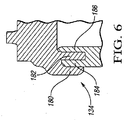
図5は、キャビティ132を形成する、別の形態のハウジング118の部分的な図である。蒸気排気弁は、ハウジング118に設置してもよく、或いは、分けてもよく、又、蒸気排気弁と第1のポートとの間に延びた第1の通気管により、ハウジング118の第1のポート(図示省略)と流体的に連通している。第2のポート(図示省略)は、図2のキャニスター17へ延びている。蓋部120は、説明済みのあらゆる方法により、図1の燃料タンク11の上部12に取り付けられる。そして、蓋部120は、ラビリンスシール134により、ハウジング118と接合される。ラビリンスシール134は、図6に拡大して詳細に示されており、ハウジング118の上部周囲でハウジング118の条部184、186と嵌合する、蓋部120の条部180、182を有している。蓋部120は、アセンブリ16全体が燃料タンク11内へ設置される前に、実行可能なあらゆる取り付け方法を利用して、ハウジング118に組み付けられる。更に、ハウジング118への蓋部120の接合を促すように、タンク11への設置後に、蓋部120がまだ熱く粘性があるうちに、蓋部120をハウジング118へ嵌合することもできる。
FIG. 5 is a partial view of another form of
図7は、アセンブリ16と同様の機能を果たすように形成された、別の形態のアセンブリ216を示している。この形態において、燃料タンク210は、溶着部234で蓋部220が熱溶接されるような、開口部219を有している。蓋部220は、ハウジング218内の第2のポートではなく、一体化された第2のポート262を有している。第2のポート262は、図2のキャニスター17と流体的に連通する、第2の通気管272へ接続されている。ハウジング218は、射出成形等により、蓋部220と一体的に形成してもよい。或いは、図1のキャビティ32と同様のキャビティ232を形成するように、熱溶接、Oリングシール、ラビリンスシール、又は、別の方法により、ハウジング218を蓋部220へ溶接してもよい。燃料タンクの内部空間214へ開口した流入口38を有する弁36は、上述したように、第1の通気管64と接続される流出口40を有している。弁36がキャビティ232から分離されているため、流体は、キャビティ232内へ浸入することなく、流入口38から流出口40へ通り抜ける。図7において、第1の通気管64は、図示の便宜上、僅かに斜視図で示されている。しかしながら、図3及び図4について説明したように、ある形態において、第1の通気管64の平行な部位66、68は、他方と同じ高さにある。第1の通気管64は、タンク210が所定の角度以上に傾けられた場合に、所定の燃料の液面レベルより常に上方位置となる部位を有している。
FIG. 7 shows another form of
本発明を実施する最良の形態について詳細に説明してきたが、本発明に関連する技術に精通した者は、添付のクレームの範囲内で、本発明を実践するための様々な代替の構想や具体例を認めるであろう。 Having described in detail the best mode of carrying out the invention, those skilled in the art to which the invention pertains will be aware of various alternative concepts and implementations for practicing the invention within the scope of the appended claims. An example will be recognized.
10:蒸気制御装置、11、210:車両燃料タンク、14、214:内部空間、16、216:統合アセンブリ、17:カーボンキャニスター、18、118、218:ハウジング、20、120、220:蓋部、22、24、26、28:側壁、30:底壁、32、132、232:キャビティ、34:Oリング、36:蒸気排気弁、38:流入口、40:流出口、60:第1のポート、62:第2のポート、64:第1の通気管、66:第1の部位、68:第2の部位、70:第3の部位、71:底面、72:第2の通気管、74:部位、75:燃料の液面レベル、76:所定角度、78:別の部位、134:ラビリンスシール、234:溶着部
10: Steam control device, 11, 210: Vehicle fuel tank, 14, 214: Interior space, 16, 216: Integrated assembly, 17: Carbon canister, 18, 118, 218: Housing, 20, 120, 220:
Claims (7)
内部キャビティ(32、132、232)を形成し、該内部キャビティと流体的に連通した第1のポート(60)及び第2のポート(62)を有するハウジング(18、118、218)と、
流入口(38)及び流出口(40)を有する蒸気排気弁(36)とを含み、該蒸気排気弁は、前記ハウジングが前記燃料タンクへ設置された状態で、前記流入口から前記流出口へ前記蒸気排気弁を介して、前記燃料タンクから流体的に連通するように形成され、前記蒸気排気弁は、流体が前記キャビティに流通することなく前記流入口から前記流出口へ前記蒸気排気弁を流れるように、前記キャビティから分離され、
更に、前記蒸気排気弁の前記流出口と前記第1のポートとを接続する第1の通気管(64)と、
前記第2のポートに接続され、前記カーボンキャニスターと接続可能に形成された第2の通気管(72)とを含み、流体が、前記蒸気排気弁を通過した後、前記第1の通気管を通り、更に前記ハウジングを通ることで、前記燃料タンクから前記第2の通気管へ流れ、
前記第1の通気管は、当該アセンブリが、前記燃料タンクに設置され、所定の角度(76)以上に傾けられた場合に、少なくとも前記第1の通気管の部位(74、78)が、前記タンク内の所定の燃料の液面レベル(75)より上方位置となるように形成され、これにより、前記第2の通気管が前記カーボンキャニスターへ接続された状態で、燃料が前記カーボンキャニスターに到達することを防止するように構成され、
前記ハウジングが、複数の壁(22、24、26、28、30)と、該複数の壁に接合された蓋部(20、120、220)とを含み、前記複数の壁と前記蓋部とで前記キャビティを形成し、
更に、前記複数の壁と前記蓋部とを接合する、Oリング(34)を含み、
前記第1の通気管(64)は、前記燃料タンクが水平である場合に、水平に延びる第1の部位(66)と、該第1の部位と平行及び同じ高さの第2の部位(68)と、前記第1及び第2の部位を接続する第3の部位(70)とを含み、これにより、前記第1の通気管が水平に延びるU字形状を成していることを特徴とするアセンブリ。 An assembly (16, 216) installable in a fuel tank (11, 210) and connectable to a carbon canister (17),
A housing (18, 118, 218) having a first port (60) and a second port (62) forming an internal cavity (32, 132, 232) and in fluid communication with the internal cavity;
A steam exhaust valve (36) having an inlet (38) and an outlet (40), the steam exhaust valve from the inlet to the outlet with the housing installed in the fuel tank. The steam exhaust valve is formed to be in fluid communication with the fuel tank via the steam exhaust valve, and the steam exhaust valve connects the steam exhaust valve from the inlet to the outlet without fluid flowing through the cavity. Separated from the cavity to flow,
A first vent pipe (64) connecting the outlet of the steam exhaust valve and the first port;
A second vent pipe (72) connected to the second port and configured to be connectable to the carbon canister, and after fluid passes through the steam exhaust valve, the first vent pipe Passing through the housing further flows from the fuel tank to the second vent pipe,
When the assembly is installed in the fuel tank and tilted by a predetermined angle (76) or more, the first vent pipe has at least a portion (74, 78) of the first vent pipe. It is formed to be above the liquid level (75) of a predetermined fuel in the tank, so that the fuel reaches the carbon canister while the second vent pipe is connected to the carbon canister. It is configured to prevent the,
The housing includes a plurality of walls (22, 24, 26, 28, 30) and a lid (20, 120, 220) joined to the plurality of walls, and the plurality of walls and the lid To form the cavity,
Furthermore, an O-ring (34) for joining the plurality of walls and the lid portion is included,
When the fuel tank is horizontal, the first vent pipe (64) includes a first portion (66) extending horizontally and a second portion (parallel to and the same height as the first portion). 68) and a third portion (70) connecting the first and second portions, whereby the first vent pipe has a U-shape extending horizontally. And assembly.
カーボンキャニスター(17)と、
前記燃料タンクに設置可能であり、キャビティ(32、132、232)を形成し、該キャビティに流体的に連通された第1のポート(60)と第2のポート(62)とを有するハウジング(18、118、218)と、
該ハウジングに設置され、前記内部空間に開口した流入口(38)と流出口(40)とを有する蒸気排気弁(36)とを含み、該蒸気排気弁は、前記流入口から前記流出口へ前記蒸気排気弁を介して、前記燃料タンクから流体的に連通するように形成され、流体が前記キャビティに流通することなく前記流入口から前記流出口へ前記蒸気排気弁を流れるように、前記キャビティから分離され、
更に、前記蒸気排気弁の前記流出口と前記第1のポートとを接続する第1の通気管(64)と、
前記第2のポートと前記カーボンキャニスターとを接続する第2の通気管(72)とを含み、流体が、前記蒸気排気弁を通って前記第1の通気管へ至り、該第1の通気管を通って前記ハウジングへ至り、更に該ハウジングを通って前記第2の通気管へ至ることで、前記燃料タンクから前記カーボンキャニスターへ流れ、
前記第1の通気管は、前記ハウジングが前記燃料タンクに設置され、所定の角度(76)以上に傾けられた場合に、少なくとも前記第1の通気管の部位(74、78)が、前記タンク内の所定の燃料の液面レベル(75)より上方位置となるように形成され、これにより、燃料が前記カーボンキャニスターに到達することを防止するように構成され、
前記ハウジングが、複数の壁(22、24、26、28、30)と、該複数の壁に接合された蓋部(20、120、220)とを含み、前記複数の壁と前記蓋部とで前記キャビティを形成し、
更に、前記複数の壁と前記蓋部とを接合する、Oリング(34)を含み、
前記第1の通気管(64)は、前記燃料タンクが水平である場合に、水平に延びる第1の部位(66)と、該第1の部位と平行及び同じ高さの第2の部位(68)と、前記第1及び第2の部位を接続する第3の部位(70)とを含み、これにより、前記第1の通気管が水平に延びるU字形状を成していることを特徴とする蒸気制御装置。 A steam control device (10) for a fuel tank (11, 210) of a vehicle having an internal space (14, 214),
Carbon canister (17),
A housing having a first port (60) and a second port (62), which is installable in the fuel tank, forms a cavity (32, 132, 232) and is in fluid communication with the cavity; 18, 118, 218),
A steam exhaust valve (36) installed in the housing and having an inlet (38) and an outlet (40) open to the internal space, the steam exhaust valve from the inlet to the outlet The cavity is formed in fluid communication with the fuel tank via the steam exhaust valve, and allows the fluid to flow from the inlet to the outlet without flowing through the cavity. Separated from
A first vent pipe (64) connecting the outlet of the steam exhaust valve and the first port;
A second vent pipe (72) connecting the second port and the carbon canister, and fluid passes through the steam exhaust valve to the first vent pipe, and the first vent pipe Through the housing and further through the housing to the second vent pipe to flow from the fuel tank to the carbon canister,
When the housing is installed in the fuel tank and tilted to a predetermined angle (76) or more, the first vent pipe has at least the first vent pipe portions (74, 78) as the tank. Is formed to be at a position above the liquid level (75) of the predetermined fuel in the inside, thereby preventing the fuel from reaching the carbon canister ,
The housing includes a plurality of walls (22, 24, 26, 28, 30) and a lid (20, 120, 220) joined to the plurality of walls, and the plurality of walls and the lid To form the cavity,
Furthermore, an O-ring (34) for joining the plurality of walls and the lid portion is included,
When the fuel tank is horizontal, the first vent pipe (64) includes a first portion (66) extending horizontally and a second portion (parallel to and the same height as the first portion). 68) and a third portion (70) connecting the first and second portions, whereby the first vent pipe has a U-shape extending horizontally. Steam control device.
前記第1及び第2のポートの少なくとも第1のポートと前記蒸気排気弁の流出口とが、前記1つ以上の側壁に形成されることを特徴とする請求項5記載の蒸気排気制御装置。 The plurality of walls include one or more side walls (22, 24, 26, 28) to which the lid portion is joined, and a bottom wall (30 that is connected to the one or more side walls on the opposite side of the lid portion. And the steam exhaust valve extends from the bottom wall,
The steam exhaust control device according to claim 5 , wherein at least a first port of the first and second ports and an outlet of the steam exhaust valve are formed on the one or more side walls.
複数の壁と、内部キャビティ(132)を構成するように、前記複数の壁にOリングにより接合される蓋部(120)とを有すると供に、前記複数の壁に第1のポート(60)及び第2のポート(62)を有するハウジング(118)と、
流入口(38)及び流出口(40)を有する蒸気排気弁(36)とを含み、該蒸気排気弁は、前記ハウジングが前記燃料タンク(11)へ設置された状態で、前記流入口から前記流出口へ前記蒸気排気弁を介して、前記燃料タンクから流体的に連通するように形成され、前記蒸気排気弁は、流体が前記キャビティに流通することなく前記流入口から前記流出口へ前記排気弁を流れるように、前記キャビティから分離され、
更に、前記蒸気排気弁の前記流出口と前記第1のポートとを接続する第1の通気管(64)を含み、該第1の通気管は、第1の部位(66)と、該第1の部位に平行な第2の部位(68)と、前記第1及び第2の部位を接続する第3の部位(70)とを含み、これにより、前記第1の通気管がU字形状を成し、前記ハウジングの底面と平行に前記ハウジングから延びており、
更に、前記第2のポートに接続され、前記カーボンキャニスターと流体的な連通状態に接続できるように形成された、第2の通気管(72)を含み、
前記第1の通気管は、当該アセンブリが、前記燃料タンクに設置され、所定の角度(76)以上に傾けられた場合に、少なくとも前記第1の通気管の部位(74、78)が、前記タンク内の所定の液面レベル(75)より上方位置となるように形成され、これにより、前記第2の通気管が前記カーボンキャニスターへ接続された状態で、燃料が前記第2の通気管を通って前記カーボンキャニスターに到達することを防止するように構成されていることを特徴とするアセンブリ。
An assembly (16) installable in a fuel tank (11) and connectable to a carbon canister (17),
In addition to having a plurality of walls and a lid (120) joined to the plurality of walls by an O-ring so as to form an internal cavity (132), a first port (60) is formed in the plurality of walls. And a housing (118) having a second port (62);
A steam exhaust valve (36) having an inlet (38) and an outlet (40), the steam exhaust valve from the inlet with the housing being installed in the fuel tank (11). The steam exhaust valve is formed to be in fluid communication with the fuel tank from the fuel tank via the steam exhaust valve, and the steam exhaust valve is configured to discharge the fluid from the inlet to the outlet without flowing through the cavity. Separated from the cavity to flow through the valve;
And a first vent pipe (64) connecting the outlet of the steam exhaust valve and the first port, the first vent pipe including a first portion (66) and the first vent pipe. A second part (68) parallel to one part and a third part (70) connecting the first and second parts, whereby the first vent pipe is U-shaped. And extending from the housing in parallel with the bottom surface of the housing,
And a second vent pipe (72) connected to the second port and configured to be connected in fluid communication with the carbon canister,
When the assembly is installed in the fuel tank and tilted by a predetermined angle (76) or more, the first vent pipe has at least a portion (74, 78) of the first vent pipe. It is formed so as to be located above a predetermined liquid level (75) in the tank, so that the fuel can pass through the second vent pipe while the second vent pipe is connected to the carbon canister. An assembly configured to prevent the carbon canister from passing through.
Applications Claiming Priority (3)
| Application Number | Priority Date | Filing Date | Title |
|---|---|---|---|
| US13/162,624 US8485389B2 (en) | 2011-06-17 | 2011-06-17 | Assembly with vapor vent valve and liquid trap for static leak prevention in vapor control system |
| US13/162,624 | 2011-06-17 | ||
| PCT/IB2012/001181 WO2012172419A1 (en) | 2011-06-17 | 2012-06-15 | Assembly with vapor vent valve and liquid trap for static leak prevention in vapor control system |
Publications (3)
| Publication Number | Publication Date |
|---|---|
| JP2014517206A JP2014517206A (en) | 2014-07-17 |
| JP2014517206A5 JP2014517206A5 (en) | 2015-07-02 |
| JP6012722B2 true JP6012722B2 (en) | 2016-10-25 |
Family
ID=46604373
Family Applications (1)
| Application Number | Title | Priority Date | Filing Date |
|---|---|---|---|
| JP2014515302A Active JP6012722B2 (en) | 2011-06-17 | 2012-06-15 | Assembly with steam exhaust valve and liquid leakage prevention mechanism to prevent static leakage in steam control device |
Country Status (6)
| Country | Link |
|---|---|
| US (1) | US8485389B2 (en) |
| EP (1) | EP2720895B1 (en) |
| JP (1) | JP6012722B2 (en) |
| KR (1) | KR20140029489A (en) |
| CN (2) | CN202851201U (en) |
| WO (1) | WO2012172419A1 (en) |
Families Citing this family (7)
| Publication number | Priority date | Publication date | Assignee | Title |
|---|---|---|---|---|
| JP2014523360A (en) * | 2011-05-30 | 2014-09-11 | ボルボ コンストラクション イクイップメント アーベー | Fuel tank for construction machinery |
| US8485389B2 (en) * | 2011-06-17 | 2013-07-16 | Eaton Corporation | Assembly with vapor vent valve and liquid trap for static leak prevention in vapor control system |
| US9045038B2 (en) * | 2011-12-22 | 2015-06-02 | Eaton Corporation | Liquid trap with integral jet pump |
| US10253787B2 (en) | 2013-02-01 | 2019-04-09 | Eaton Intelligent Power Limited | Self-aligning jet pump assembly |
| US9168829B2 (en) | 2013-07-17 | 2015-10-27 | Ford Global Technologies, Llc | Vapor storage device having a diffuser plate and dome |
| WO2016130681A1 (en) * | 2015-02-10 | 2016-08-18 | Eaton Corporation | Vent line routing configuration for fuel system |
| WO2016160782A1 (en) * | 2015-03-29 | 2016-10-06 | Eaton Corporation | Fuel system having vent point valve |
Family Cites Families (23)
| Publication number | Priority date | Publication date | Assignee | Title |
|---|---|---|---|---|
| US3662780A (en) * | 1967-10-31 | 1972-05-16 | Robert E Marsh | Fluid flow directing structure for pressure vessel |
| DE2912214C2 (en) * | 1979-03-28 | 1983-02-24 | Daimler-Benz Ag, 7000 Stuttgart | Ventilation device for fuel tanks of vehicles, in particular of motor vehicles |
| JPH0724611Y2 (en) * | 1989-05-11 | 1995-06-05 | 本田技研工業株式会社 | Lid structure of gas-liquid separator in internal combustion engine |
| JP3232471B2 (en) * | 1995-07-27 | 2001-11-26 | 株式会社ケーヒン | Steam separator in marine engines |
| JPH11287160A (en) * | 1998-03-31 | 1999-10-19 | Suzuki Motor Corp | Evaporation fuel recovering device |
| US6276387B1 (en) * | 1999-06-08 | 2001-08-21 | Delphi Technologies, Inc. | Fuel vapor control apparatus |
| US6302137B1 (en) * | 1999-09-22 | 2001-10-16 | Stant Manufacturing Inc. | Fuel tank valve with internal fuel tank vent tube |
| JP2001323854A (en) * | 2000-03-09 | 2001-11-22 | Toyoda Gosei Co Ltd | Fuel cutoff valve and method of manufacturing the same |
| DE20019968U1 (en) | 2000-11-23 | 2001-02-08 | Kautex Textron Gmbh & Co Kg | Device for supplying fuel to a motor vehicle |
| DE10063414A1 (en) * | 2000-12-19 | 2002-06-27 | Kautex Textron Gmbh & Co Kg | Fuel tank |
| DE10209491A1 (en) | 2002-03-05 | 2003-09-18 | Ti Automotive Technology Ct Gm | Fuel tank with venting system has inlet opening in form of open line end and liquid separator arranged between inlet opening and active carbon filter |
| DE10227471A1 (en) * | 2002-06-20 | 2004-01-15 | Daimlerchrysler Ag | Fuel tank system |
| US6895989B2 (en) | 2003-04-15 | 2005-05-24 | Raval-Agriculture Cooperative Societies, Ltd. | Dynamic liquid fuel trap |
| US6883500B2 (en) * | 2003-07-09 | 2005-04-26 | Denso International America, Inc. | Fuel pump module with improved vapor vent manifold |
| CA2536258C (en) * | 2003-09-09 | 2013-11-19 | Aron Joseph Clarkson | Dispensing closure |
| US20050127078A1 (en) * | 2003-12-11 | 2005-06-16 | Vorenkamp Erich J. | Fuel tank assembly and method of assembly |
| US7475773B2 (en) * | 2005-02-01 | 2009-01-13 | Airsec S.A.S. | Container for moisture-sensitive goods |
| JP2006220081A (en) * | 2005-02-10 | 2006-08-24 | Hitachi Ltd | Fuel feeding device |
| DE102005011026B4 (en) | 2005-03-10 | 2014-01-02 | Volkswagen Ag | Device for separating a fuel / air mixture and separation of fuel from this mixture |
| JP4492441B2 (en) * | 2005-05-31 | 2010-06-30 | 豊田合成株式会社 | Gas-liquid separator |
| WO2009139130A1 (en) * | 2008-05-12 | 2009-11-19 | 株式会社ミツバ | Fuel pump |
| DE102009049799B4 (en) | 2009-10-16 | 2018-07-12 | Kautex Textron Gmbh & Co. Kg | Fuel tank for a car |
| US8485389B2 (en) * | 2011-06-17 | 2013-07-16 | Eaton Corporation | Assembly with vapor vent valve and liquid trap for static leak prevention in vapor control system |
-
2011
- 2011-06-17 US US13/162,624 patent/US8485389B2/en active Active
-
2012
- 2012-06-15 WO PCT/IB2012/001181 patent/WO2012172419A1/en active Application Filing
- 2012-06-15 KR KR20137033206A patent/KR20140029489A/en not_active Application Discontinuation
- 2012-06-15 JP JP2014515302A patent/JP6012722B2/en active Active
- 2012-06-15 EP EP12743212.8A patent/EP2720895B1/en active Active
- 2012-06-18 CN CN2012203751831U patent/CN202851201U/en not_active Expired - Fee Related
- 2012-06-18 CN CN2012102688163A patent/CN103147883A/en active Pending
Also Published As
| Publication number | Publication date |
|---|---|
| CN202851201U (en) | 2013-04-03 |
| CN103147883A (en) | 2013-06-12 |
| JP2014517206A (en) | 2014-07-17 |
| KR20140029489A (en) | 2014-03-10 |
| EP2720895B1 (en) | 2015-05-27 |
| US8485389B2 (en) | 2013-07-16 |
| WO2012172419A1 (en) | 2012-12-20 |
| US20120318814A1 (en) | 2012-12-20 |
| EP2720895A1 (en) | 2014-04-23 |
Similar Documents
| Publication | Publication Date | Title |
|---|---|---|
| JP6012722B2 (en) | Assembly with steam exhaust valve and liquid leakage prevention mechanism to prevent static leakage in steam control device | |
| US8910652B2 (en) | Fuel ventilation system valve | |
| JP4615169B2 (en) | valve | |
| RU2454589C2 (en) | Tube ventilation system for fuel tank | |
| US8596311B2 (en) | Valve assembly for a fuel recirculation line | |
| JP2006266267A (en) | Fuel evaporative emission control system for small engine and its method | |
| JP4074113B2 (en) | Connector for fuel tank | |
| JP6295905B2 (en) | Fuel shut-off valve | |
| KR101191747B1 (en) | Capless filler tube assembly for car | |
| JP5180761B2 (en) | Intake manifold for internal combustion engine | |
| WO2018085325A1 (en) | Fill limit venting valve with high shut-off height | |
| JP5660070B2 (en) | Fuel shut-off valve | |
| JP2005127328A (en) | Vapor vent valve for fuel pump module | |
| JP2002285929A (en) | Over-refueling preventive valve | |
| JP2011046369A (en) | Fuel shutting-off valve | |
| JP6389228B2 (en) | Filler neck assembly and manufacturing method thereof | |
| CN100404300C (en) | Connecting structure for parts in fuel tank made of resin | |
| JP4193782B2 (en) | Fuel shut-off valve | |
| JP2010071412A (en) | Fuel shut off valve | |
| WO2017042988A1 (en) | Fuel tank valve | |
| JPS5921995Y2 (en) | Motorcycle breather device | |
| JP5431030B2 (en) | Fuel tank | |
| US9347403B2 (en) | Fuel tank | |
| JP4806480B2 (en) | Evaporative fuel emission suppression device for fuel tank | |
| CN107576066B (en) | Indoor combustion device |
Legal Events
| Date | Code | Title | Description |
|---|---|---|---|
| A521 | Request for written amendment filed |
Free format text: JAPANESE INTERMEDIATE CODE: A523 Effective date: 20150513 |
|
| A621 | Written request for application examination |
Free format text: JAPANESE INTERMEDIATE CODE: A621 Effective date: 20150513 |
|
| A131 | Notification of reasons for refusal |
Free format text: JAPANESE INTERMEDIATE CODE: A131 Effective date: 20151224 |
|
| A977 | Report on retrieval |
Free format text: JAPANESE INTERMEDIATE CODE: A971007 Effective date: 20151225 |
|
| A521 | Request for written amendment filed |
Free format text: JAPANESE INTERMEDIATE CODE: A523 Effective date: 20160322 |
|
| TRDD | Decision of grant or rejection written | ||
| A01 | Written decision to grant a patent or to grant a registration (utility model) |
Free format text: JAPANESE INTERMEDIATE CODE: A01 Effective date: 20160831 |
|
| A61 | First payment of annual fees (during grant procedure) |
Free format text: JAPANESE INTERMEDIATE CODE: A61 Effective date: 20160920 |
|
| R150 | Certificate of patent or registration of utility model |
Ref document number: 6012722 Country of ref document: JP Free format text: JAPANESE INTERMEDIATE CODE: R150 |
|
| R250 | Receipt of annual fees |
Free format text: JAPANESE INTERMEDIATE CODE: R250 |
|
| R250 | Receipt of annual fees |
Free format text: JAPANESE INTERMEDIATE CODE: R250 |
|
| S111 | Request for change of ownership or part of ownership |
Free format text: JAPANESE INTERMEDIATE CODE: R313113 |
|
| S531 | Written request for registration of change of domicile |
Free format text: JAPANESE INTERMEDIATE CODE: R313531 |
|
| R350 | Written notification of registration of transfer |
Free format text: JAPANESE INTERMEDIATE CODE: R350 |
|
| R250 | Receipt of annual fees |
Free format text: JAPANESE INTERMEDIATE CODE: R250 |
|
| R250 | Receipt of annual fees |
Free format text: JAPANESE INTERMEDIATE CODE: R250 |
|
| R250 | Receipt of annual fees |
Free format text: JAPANESE INTERMEDIATE CODE: R250 |