JP5180761B2 - Intake manifold for internal combustion engine - Google Patents
Intake manifold for internal combustion engine Download PDFInfo
- Publication number
- JP5180761B2 JP5180761B2 JP2008254904A JP2008254904A JP5180761B2 JP 5180761 B2 JP5180761 B2 JP 5180761B2 JP 2008254904 A JP2008254904 A JP 2008254904A JP 2008254904 A JP2008254904 A JP 2008254904A JP 5180761 B2 JP5180761 B2 JP 5180761B2
- Authority
- JP
- Japan
- Prior art keywords
- gas introduction
- gas
- intake pipe
- combustion engine
- internal combustion
- Prior art date
- Legal status (The legal status is an assumption and is not a legal conclusion. Google has not performed a legal analysis and makes no representation as to the accuracy of the status listed.)
- Active
Links
Images


Description
この発明は、内燃機関において、ブローバイガスを導入するためのガス導入口が吸気管に開口された構成のインテークマニホールドに関するものである。 The present invention relates to an intake manifold having a structure in which a gas inlet for introducing blow-by gas is opened to an intake pipe in an internal combustion engine.
従来、この種の技術としては、例えば特許文献1に記載されたインテークマニホールドがある。図9に示すように、このインテークマニホールドは、各吸気管50におけるコレクタ(サージタンク)51側の端部にガス導入用の貫通孔52を形成し、ブローバイガス導入用のブローバイガス管53に形成されたガス孔54を貫通孔52に連通させている。
Conventionally, as this type of technique, there is an intake manifold described in Patent Document 1, for example. As shown in FIG. 9, this intake manifold is formed with a through
また、特許文献2に記載されたインテークマニホールドは、インテークマニホールド全体を、合成樹脂製の第1〜第3の部材によって構成するものであり、ブローバイガス管は、第1の部材に一体形成された第1通路と、第2の部材に一体形成された第2通路とにより形成される。そして、ブローバイガス管は、第1の部材に形成されている貫通孔を通じて吸気管の内部に連通される。
ところで、上記特許文献1に記載の構成は、ブローバイガス管53のガス孔54が同管53の中腹、つまり高さ方向中間部に形成された構成であるため、ブローバイガス管53内の水が吸気管50側に円滑に排出されず、ガス孔54の近辺に溜まりやすい。この結果、水が凍結してガス孔54や貫通孔52が塞がれ、ブローバイガスが吸気管50に導入されなくなるおそれがあった。また、上記特許文献2には、ブローバイガス管内の水を吸気管側へ円滑に排出させるための構成に関しては何らの開示もない。
By the way, the configuration described in Patent Document 1 is a configuration in which the
この発明は、このような従来の技術に存在する問題点に着目してなされたものである。その目的とするところは、寒冷時においてブローバイガス管内の水を吸気管側へ円滑に排出させることができる内燃機関のインテークマニホールドを提供することにある。 The present invention has been made paying attention to such problems existing in the prior art. An object of the present invention is to provide an intake manifold for an internal combustion engine that can smoothly discharge water in the blow-by gas pipe to the intake pipe side during cold weather.
上記の目的を達成するために、請求項1に記載の発明は、吸気管の管壁に、同管内にブローバイガスを導入するためのガス導入口を開口させ、このガス導入口にブローバイガスのガス導入路を接続した内燃機関のインテークマニホールドにおいて、前記ガス導入路の前記ガス導入口への接続側開口の下面を前記ガス導入口に向かって下降傾斜させるとともに、その接続側開口の下縁部を前記ガス導入口の下側面よりも高い位置に配置し、前記ガス導入口の側面を、前記吸気管の管壁の外側から内側に向かって拡がる傾斜面としたことを特徴とする。 In order to achieve the above object, according to the first aspect of the present invention, a gas inlet for introducing blowby gas into the pipe wall of the intake pipe is opened, and blowby gas is introduced into the gas inlet. In the intake manifold of the internal combustion engine to which the gas introduction path is connected, the lower surface of the connection side opening of the gas introduction path to the gas introduction port is inclined downward toward the gas introduction port, and the lower edge portion of the connection side opening Is arranged at a position higher than the lower side surface of the gas introduction port, and the side surface of the gas introduction port is an inclined surface that extends from the outside to the inside of the pipe wall of the intake pipe .
請求項2に記載の発明は、前記ガス導入口の下側面を、前記吸気管の外側から内側に向かって下降傾斜させたことを特徴とする。
請求項3に記載の発明は、前記ガス導入口の下側面を直線状としたことを特徴とする。
The invention described in claim 2 is characterized in that the lower side surface of the gas inlet is inclined downward from the outside to the inside of the intake pipe.
The invention described in claim 3 is characterized in that the lower side surface of the gas inlet is linear.
請求項4に記載の発明は、前記吸気管は合成樹脂により構成され、その吸気管に合成樹脂製のガス導入室ハウジングをその外周縁において固着して前記ガス導入口に対応するとともに、前記ガス導入路を構成するガス導入室を形成したことを特徴とする。 According to a fourth aspect of the present invention, the intake pipe is made of a synthetic resin, and a gas introduction chamber housing made of synthetic resin is fixed to the intake pipe at an outer peripheral edge thereof to correspond to the gas introduction port, and the gas A gas introduction chamber constituting the introduction path is formed.
請求項5に記載の発明は、前記ガス導入室ハウジングはその外周縁において前記吸気管に振動溶着され、前記接続側開口の下縁部とその外側の溶着部との間には振動溶着に伴うバリを収容するための逃がし溝を形成したことを特徴とする。 According to a fifth aspect of the present invention, the gas introduction chamber housing is vibration welded to the intake pipe at an outer peripheral edge thereof, and vibration welding occurs between a lower edge portion of the connection side opening and a weld portion outside the connection side opening. An escape groove for accommodating a burr is formed.
請求項6に記載の発明は、前記ガス導入口は前記ガス導入室の下端に位置するとともに、その下端位置における吸気管の管壁に前記接続側開口の下縁部が近接または軽く接触していることを特徴とする。 According to a sixth aspect of the present invention, the gas introduction port is located at the lower end of the gas introduction chamber, and the lower edge portion of the connection side opening is close to or lightly contacts the pipe wall of the intake pipe at the lower end position. It is characterized by being.
(作用)
この発明によれば、ガス導入路の開口がガス導入口に向かって下降傾斜するとともに、開口縁部がガス導入口の下側面よりも高い位置に配置される。従って、ガス導入路の水は、ガス導入路の内側の下面に沿って吸気管のガス導入口に達し、さらにガス導入口の下側面に沿って吸気管内に流入する。従って、ガス導入路に水が溜まらないため、寒冷時にガス導入路内で水が凍結することはなく、吸気管へのブローバイガスの導入に支障が起きることはない。
(Function)
According to this invention, the opening of the gas introduction path is inclined downward toward the gas introduction port, and the opening edge is arranged at a position higher than the lower side surface of the gas introduction port. Therefore, the water in the gas introduction path reaches the gas introduction port of the intake pipe along the inner lower surface of the gas introduction path, and further flows into the intake pipe along the lower side surface of the gas introduction opening. Accordingly, since water does not accumulate in the gas introduction path, water does not freeze in the gas introduction path during cold weather, and there is no problem in introducing the blow-by gas into the intake pipe.
この発明は、寒冷時においてブローバイガス管内の水を吸気管側へ円滑に排出させることができるという効果を発揮する。 The present invention exhibits the effect that water in the blow-by gas pipe can be smoothly discharged to the intake pipe side during cold weather.
次に、この発明を具体化した一実施形態について、図1〜図8を用いて説明する。
図1及び図2に示すように、インテークマニホールド10は、図示しないスロットル弁を介して上流側のエアクリーナに接続されるサージタンク11と、このサージタンク11に接続された複数の吸気管12と、各吸気管12を内燃機関Egのシリンダブロックに接続するためのフランジ部13とを備えている。なお、複数の吸気管12は、サージタンク11側において一体化されている。このインテークマニホールド10は、合成樹脂製の4つの成形部材、すなわち、マニホールド本体14、タンクカバー15、吸気管ハウジング16及び、ガス導入路を構成するガス導入室ハウジング17を一体化して構成されている。
Next, an embodiment embodying the present invention will be described with reference to FIGS.
As shown in FIGS. 1 and 2, the
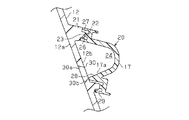
図3に示すように、各吸気管12は、吸気流の方向を90°以上の角度で変える第1湾曲部18と、この第1湾曲部18の下流において同一方向へ湾曲する第2湾曲部19とを備えている。各吸気管12の第1湾曲部18の内コーナ側における管壁12aの外側には、内燃機関Egのクランクケースからのブローバイガスを各吸気管12内に導入するためのガス導入部20が設けられている。
As shown in FIG. 3, each
このガス導入部20は、以下のように構成されている。すなわち、図4及び図5に示すように、吸気管12が一体化された部分の外側には平坦部12bが形成され、その周囲には環状の座部21が突出形成されている。座部21の先端面には、吸気管側溶着リブ22が形成されている。図5に示すように、ガス導入室ハウジング17は、その周縁のハウジング側溶着リブ23において前記吸気管側溶着リブ22に振動溶着されている。そして、前記平坦部12bとガス導入室ハウジング17の内側面との間には、後述するガス導入口30に対応するとともにガス導入路を構成するガス導入室24が形成されている。ガス導入室ハウジング17の一端には接続部(図1及び図2に図示)25が形成され、この接続部25にガス導入路を構成するブローバイガス配管(図示しない)が接続され、接続部25を介してブローバイガスがガス導入室24内に導入される。前記ハウジング側溶着リブ23の内外には、内側バリ逃がし溝26及び外側バリ逃がし溝27を介して内側覆い片28及び外側覆い片29が形成されている。この内側覆い片28及び外側覆い片29は、吸気管12の外側面または座部21の先端面に対してわずかな隙間をあけて対応するか、あるいは、ごくわずかな接触圧で接触している。前記平坦部12bには、吸気管12毎に、ガス導入室24を吸気管12内に連通させるガス導入口30が形成されている。
The
前記ガス導入室ハウジング17の内側の下面17aは、前記ガス導入口30に向かって下降傾斜されている。また、図5、図6及び図8に示すように、ガス導入口30の側面は、吸気管12の外側から内側に向かって拡がる傾斜面30aとされている。従って、ガス導入口30の下側面は、吸気管12の内側に向かって下降傾斜する直線状の傾斜面30bとされている。さらに、前記ガス導入室ハウジング17の下面17aの下縁部は、前記傾斜面30bの上縁よりも高いところに配置されている。
An inner lower surface 17 a of the gas
上記のように構成されたこの実施形態は、マニホールド本体14、タンクカバー15、吸気管ハウジング16及びガス導入室ハウジング17の各部材を振動溶着により一体接合することで組み立てられる。前記ガス導入部20は、マニホールド本体14に形成された座部21の吸気管側溶着リブ22に対して、ガス導入室ハウジング17のハウジング側溶着リブ23を振動溶着することにより形成される。このとき、溶着部である両溶着リブ22,23間にバリが発生して溶着リブ22,23から分離することがあるが、このバリは、内側バリ逃がし溝26及び外側バリ逃がし溝27内に収められる。また、内側覆い片28の下縁部は、吸気管12の平坦部12bに対してわずかな隙間をあけて対応するか、あるいは、ごくわずかな接触圧で接触する。このため、内側覆い片28の下縁部が吸気管12の管壁12aに溶着されることはなく、従って、バリが発生することはなく、ガス導入口30が吸気管12の内側に落下することはない。
This embodiment configured as described above is assembled by integrally joining the members of the
さて、内燃機関Egの運転状態においては、そのクランクケースからのブローバイガスがガス導入部20のガス導入室24内に導入され、ガス導入室24からガス導入口30を通じて各吸気管12の流路に導入される。
Now, in the operating state of the internal combustion engine Eg, blow-by gas from the crankcase is introduced into the
ここで、ガス導入室24に導入されたブローバイガスが、低温環境下で温度低下されると、ブローバイガス中の水分が結露してガス導入室24内に水滴が生成されることがある。
Here, when the temperature of the blow-by gas introduced into the
この場合、この実施形態においては、ガス導入室ハウジング17の下面17aがガス導入口30に向かって下降傾斜するとともに、下面17aの下縁部がガス導入口30の傾斜面30bよりも高い位置に配置されている。加えて、ガス導入室ハウジング17の下面17a上から水滴が流れ込むガス導入口30の下側面が、吸気管12の管壁12aの外側から内側に向かって下降傾斜する傾斜面30bとされている。この構成により、ガス導入室24の水は、ガス導入室ハウジング17の下面17aに沿って吸気管12のガス導入口30側へ流れ、ガス導入口30の傾斜面30bに沿って吸気管12の内側に移動する。従って、ガス導入室24内に水が溜まらないため、寒冷時にガス導入室24内で水が凍結することはなく、ガス導入口30が氷で塞がれることが防止される。従って、吸気管12へのブローバイガスの導入に支障が起きることはない。なお、吸気管12内に移動した水は吸気流とともに内燃機関Egの吸気側に移動されるが、その水の量はごくわずかであるため、内燃機関Egの作動には全く問題がない。
In this case, in this embodiment, the lower surface 17 a of the gas
この実施形態によれば、以下の各効果を得ることができる。
(1)ガス導入室24を形成するガス導入室ハウジング17の内側の下面17aをガス導入口30に向かって下降傾斜させるとともに、下面17aの下縁部をガス導入口30の下側面よりも高い位置に配置した。このような構成により、ガス導入室24内の水を円滑にガス導入口30側へ排出させてガス導入室24及びガス導入口30内が氷結されないようにしたので、ブローバイガスの導入に支障が起きないようにすることができる。
According to this embodiment, the following effects can be obtained.
(1) The lower surface 17a inside the gas
(2)ガス導入口30の下側面を、吸気管12の外側から内側へ向かって下降傾斜する傾斜面30bとした。この構成により、ガス導入室24からガス導入口30側へ流入した水を傾斜面30bに沿って吸気管12内に円滑に排出させ、ガス導入口30が氷で塞がれないようにすることができる。
(2) The lower side surface of the
(3)ガス導入口30の傾斜面30bを直線状としたので、ガス導入室24からガス導入口30へ流入した水を、直線状の傾斜面30bに沿って一層円滑に吸気管12内へ排出させることができる。
(3) Since the
(4)合成樹脂製の吸気管12に合成樹脂製のガス導入室ハウジング17をその外周縁において固着することにより、ガス導入口30に対応するガス導入室24を形成した。このため、各吸気管12にブローバイガスを供給するための構成を簡素化できる。
(4) The
(5)ガス導入室ハウジング17を吸気管側溶着リブ22において吸気管12に振動溶着するようにし、振動溶着に伴うバリを収容する内側バリ逃がし溝26を形成する内側覆い片28によりガス導入室ハウジング17の内側の下面を構成した。従って、ガス導入室ハウジング17の構成を簡素化できる。
(5) The gas
(6)ガス導入口30をガス導入室24の下端に位置させるとともに、その下端位置における吸気管12の管壁12aにガス導入室ハウジング17の内側覆い片28の下縁部を近接または軽く接触させた。従って、ガス導入室24からガス導入口30へ水を適切に排出させることができる。なお、この水は、内側覆い片28の下縁部と吸気管12の外側面との間から内側バリ逃がし溝26内に至る場合もあるが、この場合、この水はいずれ気化して吸気管12内に移動される。
(6) The
(7)ガス導入口30の側面全体を、吸気管12の管壁12aの外面から内面に向かって拡がる傾斜面30aとした。この構成により、吸気管12内を流れる吸気流がガス導入口30の内面側開口縁を起点として渦を巻くことを防止できるため、吸気流の乱れを有効に防止することができる。
(7) The entire side surface of the
なお、この実施形態は、次のように変更して具体化することも可能である。
・図7(b)に示すように、ガス導入口30の傾斜面30bを曲面状とすること。
・図7(c)に示すように、ガス導入口30の下側面のみを傾斜面30bとすること。
In addition, this embodiment can also be changed and embodied as follows.
-As shown in FIG.7 (b), let the
-As shown in FIG.7 (c), let only the lower surface of the
・図6に二点鎖線で示すように、1つの吸気管12の幅方向に2つのガス導入口30を設けること。
・ガス導入室ハウジング17を設けることなく、ブローバイガス管をガス導入口30に直接接続すること。
As shown by a two-dot chain line in FIG. 6, two
The blow-by gas pipe is directly connected to the
以下、前記実施形態から把握される技術的思想を記載する。
(1)請求項1〜6のいずれか一項に記載の内燃機関のインテークマニホールドにおいて、前記ガス導入口の側面を、吸気管の外側から内側に向かって拡がるように傾斜させたことを特徴とする内燃機関のインテークマニホールド。
Hereinafter, the technical idea grasped from the embodiment will be described.
(1) The intake manifold of the internal combustion engine according to any one of claims 1 to 6, wherein a side surface of the gas introduction port is inclined so as to expand from the outside to the inside of the intake pipe. An intake manifold for an internal combustion engine.
10…インテークマニホールド、12…吸気管、12a…管壁、17…ガス導入室ハウジング、17a…下面、20…ガス導入路を構成するガス導入室、22…吸気管側溶着リブ、24…ガス導入室、26…逃がし溝としての内側バリ逃がし溝、28…内側覆い片、30…ガス導入口、30a…側面としての傾斜面、30b…下側面としての傾斜面、Eg…内燃機関。
DESCRIPTION OF
Claims (6)
前記ガス導入路の前記ガス導入口への接続側開口の下面を前記ガス導入口に向かって下降傾斜させるとともに、その接続側開口の下縁部を前記ガス導入口の下側面よりも高い位置に配置し、
前記ガス導入口の側面を、前記吸気管の管壁の外側から内側に向かって拡がる傾斜面としたことを特徴とする内燃機関のインテークマニホールド。 In an intake manifold of an internal combustion engine in which a gas inlet for introducing blow-by gas into the pipe is opened on the pipe wall of the intake pipe, and a gas inlet for blow-by gas is connected to the gas inlet,
The lower surface of the connection side opening to the gas introduction port of the gas introduction path is inclined downward toward the gas introduction port, and the lower edge of the connection side opening is positioned higher than the lower side surface of the gas introduction port arrangement and,
An intake manifold for an internal combustion engine , wherein a side surface of the gas inlet port is an inclined surface that extends from the outside to the inside of the pipe wall of the intake pipe .
その吸気管に合成樹脂製のガス導入室ハウジングをその外周縁において固着して前記ガス導入口に対応するとともに、前記ガス導入路を構成するガス導入室を形成したことを特徴とする請求項1〜3のいずれか一項に記載の内燃機関のインテークマニホールド。 The intake pipe is made of synthetic resin,
2. A gas introduction chamber housing made of synthetic resin is fixed to the intake pipe at an outer peripheral edge thereof to correspond to the gas introduction port, and a gas introduction chamber constituting the gas introduction path is formed. The intake manifold of the internal combustion engine as described in any one of -3.
Priority Applications (1)
| Application Number | Priority Date | Filing Date | Title |
|---|---|---|---|
| JP2008254904A JP5180761B2 (en) | 2008-09-30 | 2008-09-30 | Intake manifold for internal combustion engine |
Applications Claiming Priority (1)
| Application Number | Priority Date | Filing Date | Title |
|---|---|---|---|
| JP2008254904A JP5180761B2 (en) | 2008-09-30 | 2008-09-30 | Intake manifold for internal combustion engine |
Publications (2)
| Publication Number | Publication Date |
|---|---|
| JP2010084640A JP2010084640A (en) | 2010-04-15 |
| JP5180761B2 true JP5180761B2 (en) | 2013-04-10 |
Family
ID=42248845
Family Applications (1)
| Application Number | Title | Priority Date | Filing Date |
|---|---|---|---|
| JP2008254904A Active JP5180761B2 (en) | 2008-09-30 | 2008-09-30 | Intake manifold for internal combustion engine |
Country Status (1)
| Country | Link |
|---|---|
| JP (1) | JP5180761B2 (en) |
Cited By (2)
| Publication number | Priority date | Publication date | Assignee | Title |
|---|---|---|---|---|
| JP7026117B2 (en) | 2017-08-31 | 2022-02-25 | 株式会社島津製作所 | Atomic absorption spectrophotometer and atomic absorption measurement method |
| JP7427732B2 (en) | 2017-12-26 | 2024-02-05 | 株式会社日立ハイテク | Automatic analyzer and automatic analysis method |
Families Citing this family (4)
| Publication number | Priority date | Publication date | Assignee | Title |
|---|---|---|---|---|
| JP5891813B2 (en) | 2012-01-25 | 2016-03-23 | アイシン精機株式会社 | Freezing prevention structure of PCV passage and intake manifold |
| JP6142477B2 (en) | 2012-07-31 | 2017-06-07 | アイシン精機株式会社 | Intake manifold |
| JP2020002828A (en) * | 2018-06-26 | 2020-01-09 | トヨタ紡織株式会社 | Air intake duct for internal combustion engine |
| JP7287261B2 (en) * | 2019-12-18 | 2023-06-06 | トヨタ紡織株式会社 | intake duct |
Family Cites Families (7)
| Publication number | Priority date | Publication date | Assignee | Title |
|---|---|---|---|---|
| JPS6328816U (en) * | 1986-08-11 | 1988-02-25 | ||
| JPH0218648U (en) * | 1988-07-15 | 1990-02-07 | ||
| JP2683046B2 (en) * | 1988-07-28 | 1997-11-26 | マツダ株式会社 | Blow-by gas processing equipment for engines |
| JP2511758Y2 (en) * | 1989-09-01 | 1996-09-25 | 日産ディーゼル工業株式会社 | Blow-by gas recirculation system for internal combustion engine |
| JPH07189837A (en) * | 1993-12-28 | 1995-07-28 | Showa Alum Corp | Intake manifold |
| JPH1182197A (en) * | 1997-09-08 | 1999-03-26 | Denso Corp | Intake device for internal combustion engine |
| JP5136306B2 (en) * | 2008-09-09 | 2013-02-06 | トヨタ自動車株式会社 | Intake manifold |
-
2008
- 2008-09-30 JP JP2008254904A patent/JP5180761B2/en active Active
Cited By (2)
| Publication number | Priority date | Publication date | Assignee | Title |
|---|---|---|---|---|
| JP7026117B2 (en) | 2017-08-31 | 2022-02-25 | 株式会社島津製作所 | Atomic absorption spectrophotometer and atomic absorption measurement method |
| JP7427732B2 (en) | 2017-12-26 | 2024-02-05 | 株式会社日立ハイテク | Automatic analyzer and automatic analysis method |
Also Published As
| Publication number | Publication date |
|---|---|
| JP2010084640A (en) | 2010-04-15 |
Similar Documents
| Publication | Publication Date | Title |
|---|---|---|
| JP5180761B2 (en) | Intake manifold for internal combustion engine | |
| JP5626597B2 (en) | Intake manifold | |
| JP4550011B2 (en) | Internal combustion engine | |
| JP2006015963A (en) | Motorcycle | |
| JP6012722B2 (en) | Assembly with steam exhaust valve and liquid leakage prevention mechanism to prevent static leakage in steam control device | |
| CN111051657A (en) | Cylinder head oil separator for internal combustion engine (flow controlled oil separator) | |
| JP2006207437A (en) | Structure of blowby gas passage for internal combustion engine | |
| JP2009047141A (en) | Oil separation device for engine | |
| JP5686692B2 (en) | Resin intake manifold | |
| JP4814164B2 (en) | Intake device for internal combustion engine | |
| JP2018091310A (en) | Intake manifold of internal combustion engine | |
| JP5065217B2 (en) | Surge tank and intake manifold for internal combustion engine | |
| JP2014181678A (en) | Internal combustion engine of saddle type vehicle | |
| EP2733343B1 (en) | Intake pipe structure for internal combustion engine | |
| US9097221B2 (en) | Intake apparatus | |
| US7201129B2 (en) | Intake pipe | |
| JP2007285154A (en) | Intake manifold | |
| CN110945216B (en) | Fluid pipeline | |
| JP4422557B2 (en) | Intake manifold | |
| JP2020037918A (en) | Suction manifold | |
| JP2014145259A (en) | Intake manifold | |
| JP2014181624A (en) | Intake device of internal combustion engine | |
| JP4823159B2 (en) | Intake device for internal combustion engine | |
| JP2014105604A (en) | Intake device of internal combustion engine | |
| JP6166130B2 (en) | Intake manifold for internal combustion engine |
Legal Events
| Date | Code | Title | Description |
|---|---|---|---|
| A621 | Written request for application examination |
Free format text: JAPANESE INTERMEDIATE CODE: A621 Effective date: 20110321 |
|
| A977 | Report on retrieval |
Free format text: JAPANESE INTERMEDIATE CODE: A971007 Effective date: 20120329 |
|
| A131 | Notification of reasons for refusal |
Free format text: JAPANESE INTERMEDIATE CODE: A131 Effective date: 20120417 |
|
| A521 | Request for written amendment filed |
Free format text: JAPANESE INTERMEDIATE CODE: A523 Effective date: 20120608 |
|
| TRDD | Decision of grant or rejection written | ||
| A01 | Written decision to grant a patent or to grant a registration (utility model) |
Free format text: JAPANESE INTERMEDIATE CODE: A01 Effective date: 20121225 |
|
| A61 | First payment of annual fees (during grant procedure) |
Free format text: JAPANESE INTERMEDIATE CODE: A61 Effective date: 20130111 |
|
| R150 | Certificate of patent or registration of utility model |
Ref document number: 5180761 Country of ref document: JP Free format text: JAPANESE INTERMEDIATE CODE: R150 |
|
| R250 | Receipt of annual fees |
Free format text: JAPANESE INTERMEDIATE CODE: R250 |
|
| R250 | Receipt of annual fees |
Free format text: JAPANESE INTERMEDIATE CODE: R250 |
|
| R250 | Receipt of annual fees |
Free format text: JAPANESE INTERMEDIATE CODE: R250 |
|
| R250 | Receipt of annual fees |
Free format text: JAPANESE INTERMEDIATE CODE: R250 |
|
| R250 | Receipt of annual fees |
Free format text: JAPANESE INTERMEDIATE CODE: R250 |
|
| R250 | Receipt of annual fees |
Free format text: JAPANESE INTERMEDIATE CODE: R250 |
|
| R250 | Receipt of annual fees |
Free format text: JAPANESE INTERMEDIATE CODE: R250 |
|
| R250 | Receipt of annual fees |
Free format text: JAPANESE INTERMEDIATE CODE: R250 |