JP6011908B2 - 光レセプタクルおよびこれを備えた光モジュール - Google Patents
光レセプタクルおよびこれを備えた光モジュール Download PDFInfo
- Publication number
- JP6011908B2 JP6011908B2 JP2012060193A JP2012060193A JP6011908B2 JP 6011908 B2 JP6011908 B2 JP 6011908B2 JP 2012060193 A JP2012060193 A JP 2012060193A JP 2012060193 A JP2012060193 A JP 2012060193A JP 6011908 B2 JP6011908 B2 JP 6011908B2
- Authority
- JP
- Japan
- Prior art keywords
- light
- monitor
- lens surface
- optical
- optical receptacle
- Prior art date
- Legal status (The legal status is an assumption and is not a legal conclusion. Google has not performed a legal analysis and makes no representation as to the accuracy of the status listed.)
- Expired - Fee Related
Links
- 230000003287 optical effect Effects 0.000 title claims description 153
- 230000008878 coupling Effects 0.000 claims description 60
- 238000010168 coupling process Methods 0.000 claims description 60
- 238000005859 coupling reaction Methods 0.000 claims description 60
- 230000005540 biological transmission Effects 0.000 claims description 22
- 238000006243 chemical reaction Methods 0.000 claims description 22
- 238000012544 monitoring process Methods 0.000 claims description 7
- 239000000758 substrate Substances 0.000 claims description 7
- 238000012986 modification Methods 0.000 description 37
- 230000004048 modification Effects 0.000 description 37
- 239000013307 optical fiber Substances 0.000 description 36
- 239000000835 fiber Substances 0.000 description 16
- 239000010408 film Substances 0.000 description 5
- 239000004065 semiconductor Substances 0.000 description 5
- 238000013461 design Methods 0.000 description 4
- 238000000034 method Methods 0.000 description 4
- 239000011347 resin Substances 0.000 description 4
- 229920005989 resin Polymers 0.000 description 4
- 230000008859 change Effects 0.000 description 3
- 238000010586 diagram Methods 0.000 description 3
- 230000008901 benefit Effects 0.000 description 2
- 238000004891 communication Methods 0.000 description 2
- 230000000694 effects Effects 0.000 description 2
- 238000000465 moulding Methods 0.000 description 2
- 230000002093 peripheral effect Effects 0.000 description 2
- 238000012546 transfer Methods 0.000 description 2
- 239000004697 Polyetherimide Substances 0.000 description 1
- 239000000853 adhesive Substances 0.000 description 1
- 230000001070 adhesive effect Effects 0.000 description 1
- 230000002411 adverse Effects 0.000 description 1
- 229910052782 aluminium Inorganic materials 0.000 description 1
- 229910052737 gold Inorganic materials 0.000 description 1
- 238000007373 indentation Methods 0.000 description 1
- 238000001746 injection moulding Methods 0.000 description 1
- 238000004519 manufacturing process Methods 0.000 description 1
- 239000000463 material Substances 0.000 description 1
- 238000005259 measurement Methods 0.000 description 1
- 239000002184 metal Substances 0.000 description 1
- 229910052751 metal Inorganic materials 0.000 description 1
- 238000001579 optical reflectometry Methods 0.000 description 1
- 229920001601 polyetherimide Polymers 0.000 description 1
- 230000009467 reduction Effects 0.000 description 1
- 238000011160 research Methods 0.000 description 1
- 238000000926 separation method Methods 0.000 description 1
- 229910052709 silver Inorganic materials 0.000 description 1
- 230000000087 stabilizing effect Effects 0.000 description 1
- 239000010409 thin film Substances 0.000 description 1
Images


Classifications
-
- G—PHYSICS
- G02—OPTICS
- G02B—OPTICAL ELEMENTS, SYSTEMS OR APPARATUS
- G02B6/00—Light guides; Structural details of arrangements comprising light guides and other optical elements, e.g. couplings
- G02B6/24—Coupling light guides
- G02B6/42—Coupling light guides with opto-electronic elements
- G02B6/4201—Packages, e.g. shape, construction, internal or external details
- G02B6/4286—Optical modules with optical power monitoring
-
- G—PHYSICS
- G02—OPTICS
- G02B—OPTICAL ELEMENTS, SYSTEMS OR APPARATUS
- G02B27/00—Optical systems or apparatus not provided for by any of the groups G02B1/00 - G02B26/00, G02B30/00
- G02B27/10—Beam splitting or combining systems
- G02B27/108—Beam splitting or combining systems for sampling a portion of a beam or combining a small beam in a larger one, e.g. wherein the area ratio or power ratio of the divided beams significantly differs from unity, without spectral selectivity
-
- G—PHYSICS
- G02—OPTICS
- G02B—OPTICAL ELEMENTS, SYSTEMS OR APPARATUS
- G02B27/00—Optical systems or apparatus not provided for by any of the groups G02B1/00 - G02B26/00, G02B30/00
- G02B27/10—Beam splitting or combining systems
- G02B27/12—Beam splitting or combining systems operating by refraction only
- G02B27/123—The splitting element being a lens or a system of lenses, including arrays and surfaces with refractive power
-
- G—PHYSICS
- G02—OPTICS
- G02B—OPTICAL ELEMENTS, SYSTEMS OR APPARATUS
- G02B6/00—Light guides; Structural details of arrangements comprising light guides and other optical elements, e.g. couplings
- G02B6/24—Coupling light guides
- G02B6/42—Coupling light guides with opto-electronic elements
- G02B6/4201—Packages, e.g. shape, construction, internal or external details
- G02B6/4204—Packages, e.g. shape, construction, internal or external details the coupling comprising intermediate optical elements, e.g. lenses, holograms
- G02B6/4214—Packages, e.g. shape, construction, internal or external details the coupling comprising intermediate optical elements, e.g. lenses, holograms the intermediate optical element having redirecting reflective means, e.g. mirrors, prisms for deflecting the radiation from horizontal to down- or upward direction toward a device
-
- G—PHYSICS
- G02—OPTICS
- G02B—OPTICAL ELEMENTS, SYSTEMS OR APPARATUS
- G02B6/00—Light guides; Structural details of arrangements comprising light guides and other optical elements, e.g. couplings
- G02B6/24—Coupling light guides
- G02B6/42—Coupling light guides with opto-electronic elements
- G02B6/4201—Packages, e.g. shape, construction, internal or external details
- G02B6/4249—Packages, e.g. shape, construction, internal or external details comprising arrays of active devices and fibres
Landscapes
- Physics & Mathematics (AREA)
- General Physics & Mathematics (AREA)
- Optics & Photonics (AREA)
- Spectroscopy & Molecular Physics (AREA)
- Optical Couplings Of Light Guides (AREA)
Description
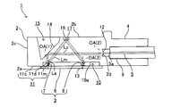
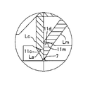
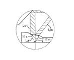
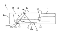
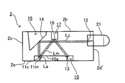
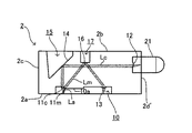
例えば、図5よび図6に示すように、モニタ用レンズ面部11mを、結合用レンズ面部11c側に向かうにしたがって光電変換装置3と反対側に傾くような下端面2aに対して所定の傾斜角を有する傾斜平面に形成してもよい。なお、この場合に、モニタ用レンズ面部11mは、下面図において図3と同様の半円形状を呈するように形成してもよい。
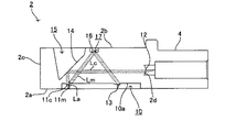
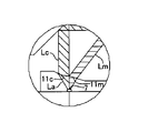
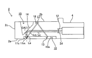
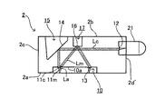
また、図7〜図9に示すように、結合用レンズ面部11cとモニタ用レンズ面部11mとを互いに連接するように形成してもよい。
さらに、図10および図11に示すように、第1の変形例(傾斜平面状のモニタ用レンズ面部11m)と第2の変形例(結合用レンズ面部11cとモニタ用レンズ面部11mとの連接)とを組み合わせるようにしてもよい。
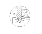
さらにまた、ファイバ結合光Lcとモニタ光Lmとの光強度比は、結合用レンズ面部11cに入射する一部のレーザ光Laとモニタ用レンズ面部11mに入射する他の一部のレーザ光Laとの光束断面積比(光軸OA(1)に垂直な断面の面積比)によって調整することができ、この光束断面積比は、両レンズ面部11c、11mの面積比によって調整することができる。
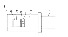
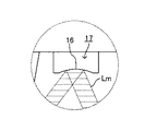
また、図14〜図16に示すように、第2の反射面16を、第3の凹部17の内底面の一部をなす凸の非球面形状の全反射面に形成してもよい。
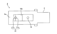
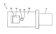
さらに、図17および図18に示すように、第3の凹部17の内底面を、円形状に形成してもよい。
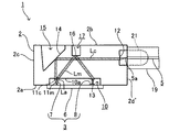
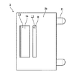
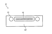
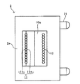
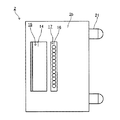
さらにまた、図19〜図22に示すように、モニタをともなう光送信の多チャンネル化に対応できるように構成してもよい。
また、図23に示すように、第1の変形例(傾斜平面状のモニタ用レンズ面部11m)と第7の変形例(多チャンネル対応)とを組み合わせるようにしてもよい。
さらに、図24および図25に示すように、第2の変形例(結合用レンズ面部11cと凹面状のモニタ用レンズ面部11mとの連接)と第7の変形例(多チャンネル対応)とを組み合わせるようにしてもよい。
さらにまた、図26に示すように、第3の変形例(結合用レンズ面部11cと傾斜平面状のモニタ用レンズ面部11mとの連接)と第7の変形例(多チャンネル対応)とを組み合わせるようにしてもよい。
また、図27に示すように、第4の変形例(ファイバ結合光Lcの光量調整)と第7の変形例(多チャンネル対応)とを組み合わせるようにしてもよい。
さらに、図28および図29に示すように、第5の変形例(非球面状の第2の反射面16)と第7の変形例(多チャンネル対応)とを組み合わせるようにしてもよい。
2 光レセプタクル
3 光電変換装置
5 光ファイバ
7 発光素子
8 受光素子
11 第1のレンズ面
11c 結合用レンズ面部
11m モニタ用レンズ面部
14 第1の反射面
16 第2の反射面
Claims (11)
- 発光素子およびこの発光素子から発光された光をモニタするためのモニタ光を受光する受光素子が基板上に実装された光電変換装置と、光伝送体との間に配置された状態で、前記発光素子と前記光伝送体とを光学的に結合可能とされた光レセプタクルであって、
光レセプタクル本体における前記光電変換装置側の第1の面上に、前記発光素子の前記光が入射するように配置され、入射した前記発光素子の光を、前記光伝送体に結合すべき結合光と前記モニタ光とに分離する第1のレンズ面と、
前記光レセプタクル本体における前記第1の面と反対側の第2の面上に、前記第1の面に対して所定の傾斜角を有するようにして前記第1のレンズ面に対向して配置され、前記第1のレンズ面側から前記結合光が到達し、この到達した結合光を前記光伝送体側に向けて反射させる第1の反射面と、
この第1の反射面によって反射された前記結合光を前記光伝送体に向けて出射させる結合光出射面と、
前記第2の面上における前記第1の反射面に対する前記光伝送体側の位置に配置され、前記第1のレンズ面側から前記モニタ光が到達し、この到達したモニタ光を前記受光素子側に向けて反射させる第2の反射面と、
この第2の反射面によって反射された前記モニタ光を前記受光素子に向けて出射させるモニタ光出射面と
を備え、
前記第1のレンズ面は、
前記発光素子の光における一部の光が入射するように配置され、入射した前記一部の光を前記結合光として前記第1の反射面に向けて進行させる結合用レンズ面部と、
前記発光素子の光における前記一部の光以外の他の一部の光が入射するように配置され、入射した前記他の一部の光を前記モニタ光として前記第2の反射面に向けて進行させるモニタ用レンズ面部と
を有するとともに
前記結合用レンズ面部は、凸面に形成され、
前記モニタ用レンズ面部は、凹面または傾斜平面に形成されている
ことを特徴とする光レセプタクル。 - 前記結合用レンズ面部、前記モニタ用レンズ面部および前記モニタ光出射面は、前記第1の面上の共通の基準平面を基準とした面形状に設計されており、
前記第1のレンズ面は、前記結合用レンズ面部と前記モニタ用レンズ面部とを接続する段差面部を有すること
を特徴とする請求項1に記載の光レセプタクル。 - 前記段差面部は、前記第1のレンズ面上の光軸に平行に配置されていること
を特徴とする請求項2に記載の光レセプタクル。 - 前記結合用レンズ面部と前記モニタ用レンズ面部とは、互いに連接されていること
を特徴とする請求項1に記載の光レセプタクル。 - 前記モニタ用レンズ面部は、前記結合用レンズ面部に対して前記光伝送体側に配置されていること
を特徴とする請求項1〜4のいずれか1項に記載の光レセプタクル。 - 前記第2の反射面は、前記モニタ光が臨界角よりも大きい入射角で内部入射し、この内部入射したモニタ光を全反射させる全反射面とされていること
を特徴とする請求項1〜5のいずれか1項に記載の光レセプタクル。 - 前記第2の反射面は、平面または凸の非球面に形成されていること
を特徴とする請求項6に記載の光レセプタクル。 - 前記第2の反射面は、前記第2の面上に凹設された凹部の内底面の少なくとも一部からなること
を特徴とする請求項6または7に記載の光レセプタクル。 - 前記第1の反射面は、前記結合光が臨界角よりも大きい入射角で内部入射し、この内部入射した結合光を全反射させる全反射面とされていること
を特徴とする請求項1〜8のいずれか1項に記載の光レセプタクル。 - 前記結合光出射面は、前記結合光を収束させつつ出射させる第2のレンズ面とされ、
前記モニタ光出射面は、前記モニタ光を収束させつつ出射させる第3のレンズ面とされていること
を特徴とする請求項1〜9のいずれか1項に記載の光レセプタクル。 - 請求項1〜10のいずれか1項に記載の光レセプタクルと、
請求項1に記載の光電変換装置と
を備えたことを特徴とする光モジュール。
Priority Applications (4)
| Application Number | Priority Date | Filing Date | Title |
|---|---|---|---|
| JP2012060193A JP6011908B2 (ja) | 2012-03-16 | 2012-03-16 | 光レセプタクルおよびこれを備えた光モジュール |
| US14/382,503 US9529166B2 (en) | 2012-03-16 | 2013-02-20 | Optical receptacle and optical module provided with same |
| PCT/JP2013/054103 WO2013136925A1 (ja) | 2012-03-16 | 2013-02-20 | 光レセプタクルおよびこれを備えた光モジュール |
| TW102109315A TWI608263B (zh) | 2012-03-16 | 2013-03-15 | Optical socket and light module with it |
Applications Claiming Priority (1)
| Application Number | Priority Date | Filing Date | Title |
|---|---|---|---|
| JP2012060193A JP6011908B2 (ja) | 2012-03-16 | 2012-03-16 | 光レセプタクルおよびこれを備えた光モジュール |
Publications (2)
| Publication Number | Publication Date |
|---|---|
| JP2013195513A JP2013195513A (ja) | 2013-09-30 |
| JP6011908B2 true JP6011908B2 (ja) | 2016-10-25 |
Family
ID=49160844
Family Applications (1)
| Application Number | Title | Priority Date | Filing Date |
|---|---|---|---|
| JP2012060193A Expired - Fee Related JP6011908B2 (ja) | 2012-03-16 | 2012-03-16 | 光レセプタクルおよびこれを備えた光モジュール |
Country Status (4)
| Country | Link |
|---|---|
| US (1) | US9529166B2 (ja) |
| JP (1) | JP6011908B2 (ja) |
| TW (1) | TWI608263B (ja) |
| WO (1) | WO2013136925A1 (ja) |
Families Citing this family (2)
| Publication number | Priority date | Publication date | Assignee | Title |
|---|---|---|---|---|
| JP2018087869A (ja) * | 2016-11-28 | 2018-06-07 | 株式会社エンプラス | 光モジュールおよび光モジュールの製造方法 |
| JP7230709B2 (ja) * | 2019-06-28 | 2023-03-01 | 住友電気工業株式会社 | 光受信器 |
Family Cites Families (16)
| Publication number | Priority date | Publication date | Assignee | Title |
|---|---|---|---|---|
| JP2003060299A (ja) * | 2001-06-07 | 2003-02-28 | Ricoh Opt Ind Co Ltd | 光出力素子・光出力素子アレイおよびレンズ素子・レンズ素子アレイ |
| US6888988B2 (en) | 2003-03-14 | 2005-05-03 | Agilent Technologies, Inc. | Small form factor all-polymer optical device with integrated dual beam path based on total internal reflection optical turn |
| WO2005033745A2 (en) * | 2003-09-29 | 2005-04-14 | Photodigm, Inc. | Method and apparatus for wavelength division multiplexing |
| JP2008151894A (ja) * | 2006-12-15 | 2008-07-03 | Enplas Corp | 光学素子およびこれを備えた光モジュール用ホルダ、光モジュールならびに光コネクタ |
| JP4914819B2 (ja) * | 2007-12-14 | 2012-04-11 | 株式会社エンプラス | 光結合素子およびこれを備えた光モジュール |
| JP2009216777A (ja) * | 2008-03-07 | 2009-09-24 | Nec Electronics Corp | 光レセプタクルおよび光レセプタクルモジュール |
| JP5025695B2 (ja) | 2009-08-07 | 2012-09-12 | 株式会社エンプラス | 光モジュール |
| JP5538108B2 (ja) | 2010-07-09 | 2014-07-02 | 株式会社エンプラス | レンズアレイおよびこれを備えた光モジュール |
| US8705975B2 (en) * | 2011-02-24 | 2014-04-22 | Avago Technologies General Ip (Singapore) Pte. Ltd. | Single wavelength bidirectional fiber optical link with beam-splitting element |
| JP6089354B2 (ja) * | 2011-10-25 | 2017-03-08 | 株式会社エンプラス | レンズアレイおよびその製造方法 |
| JP5896136B2 (ja) * | 2012-03-05 | 2016-03-30 | 株式会社エンプラス | 光レセプタクルおよびこれを備えた光モジュール |
| JP2013200347A (ja) * | 2012-03-23 | 2013-10-03 | Enplas Corp | 光レセプタクルおよびこれを備えた光モジュール |
| JP6011958B2 (ja) * | 2012-03-28 | 2016-10-25 | 株式会社エンプラス | 光レセプタクルおよびこれを備えた光モジュール |
| WO2013183272A1 (ja) * | 2012-06-05 | 2013-12-12 | 株式会社エンプラス | 光レセプタクルおよびこれを備えた光モジュール |
| US20140086579A1 (en) * | 2012-09-27 | 2014-03-27 | Avago Technologies General Ip (Singapore) Pte. Ltd | Optical coupling system, an optical communications module that incorporates the optical coupling system, and a method of using the optical coupling system |
| US9470857B2 (en) * | 2014-06-13 | 2016-10-18 | Sumitomo Electric Industries, Ltd. | Optical module with beam splitter on reflecting surface |
-
2012
- 2012-03-16 JP JP2012060193A patent/JP6011908B2/ja not_active Expired - Fee Related
-
2013
- 2013-02-20 WO PCT/JP2013/054103 patent/WO2013136925A1/ja not_active Ceased
- 2013-02-20 US US14/382,503 patent/US9529166B2/en not_active Expired - Fee Related
- 2013-03-15 TW TW102109315A patent/TWI608263B/zh not_active IP Right Cessation
Also Published As
| Publication number | Publication date |
|---|---|
| TW201341878A (zh) | 2013-10-16 |
| US9529166B2 (en) | 2016-12-27 |
| WO2013136925A1 (ja) | 2013-09-19 |
| TWI608263B (zh) | 2017-12-11 |
| JP2013195513A (ja) | 2013-09-30 |
| US20150078713A1 (en) | 2015-03-19 |
Similar Documents
| Publication | Publication Date | Title |
|---|---|---|
| JP6011958B2 (ja) | 光レセプタクルおよびこれを備えた光モジュール | |
| JP6134934B2 (ja) | 光レセプタクルおよびこれを備えた光モジュール | |
| JP5946611B2 (ja) | 光レセプタクルおよびこれを備えた光モジュール | |
| JP6205194B2 (ja) | 光レセプタクルおよび光モジュール | |
| TWI609205B (zh) | Optical socket and light module with it | |
| TWI611230B (zh) | 光插座以及光模組 | |
| JP6359848B2 (ja) | 光レセプタクルおよびこれを備えた光モジュール | |
| WO2019013313A1 (ja) | 光レセプタクルおよび光モジュール | |
| WO2016021384A1 (ja) | 光レセプタクルおよび光モジュール | |
| CN104246568B (zh) | 光插座及具备该光插座的光学模块 | |
| JP2017068212A (ja) | 光レセプタクルおよび光モジュール | |
| JP6681751B2 (ja) | 光レセプタクルおよび光モジュール | |
| JP6011908B2 (ja) | 光レセプタクルおよびこれを備えた光モジュール | |
| JP2017161579A (ja) | 光レセプタクルおよび光モジュール | |
| JP6494711B2 (ja) | 光モジュール | |
| WO2016031603A1 (ja) | 光レセプタクルおよび光モジュール |
Legal Events
| Date | Code | Title | Description |
|---|---|---|---|
| A621 | Written request for application examination |
Free format text: JAPANESE INTERMEDIATE CODE: A621 Effective date: 20150220 |
|
| A131 | Notification of reasons for refusal |
Free format text: JAPANESE INTERMEDIATE CODE: A131 Effective date: 20160202 |
|
| A521 | Request for written amendment filed |
Free format text: JAPANESE INTERMEDIATE CODE: A523 Effective date: 20160330 |
|
| TRDD | Decision of grant or rejection written | ||
| A01 | Written decision to grant a patent or to grant a registration (utility model) |
Free format text: JAPANESE INTERMEDIATE CODE: A01 Effective date: 20160823 |
|
| A61 | First payment of annual fees (during grant procedure) |
Free format text: JAPANESE INTERMEDIATE CODE: A61 Effective date: 20160908 |
|
| R150 | Certificate of patent or registration of utility model |
Ref document number: 6011908 Country of ref document: JP Free format text: JAPANESE INTERMEDIATE CODE: R150 |
|
| R250 | Receipt of annual fees |
Free format text: JAPANESE INTERMEDIATE CODE: R250 |
|
| R250 | Receipt of annual fees |
Free format text: JAPANESE INTERMEDIATE CODE: R250 |
|
| LAPS | Cancellation because of no payment of annual fees |