JP6010995B2 - Charging device, charging device control method, electric vehicle, power storage device, and power system - Google Patents
Charging device, charging device control method, electric vehicle, power storage device, and power system Download PDFInfo
- Publication number
- JP6010995B2 JP6010995B2 JP2012093677A JP2012093677A JP6010995B2 JP 6010995 B2 JP6010995 B2 JP 6010995B2 JP 2012093677 A JP2012093677 A JP 2012093677A JP 2012093677 A JP2012093677 A JP 2012093677A JP 6010995 B2 JP6010995 B2 JP 6010995B2
- Authority
- JP
- Japan
- Prior art keywords
- power
- unit
- power supply
- supply unit
- control
- Prior art date
- Legal status (The legal status is an assumption and is not a legal conclusion. Google has not performed a legal analysis and makes no representation as to the accuracy of the status listed.)
- Expired - Fee Related
Links
Images


Classifications
-
- B—PERFORMING OPERATIONS; TRANSPORTING
- B60—VEHICLES IN GENERAL
- B60L—PROPULSION OF ELECTRICALLY-PROPELLED VEHICLES; SUPPLYING ELECTRIC POWER FOR AUXILIARY EQUIPMENT OF ELECTRICALLY-PROPELLED VEHICLES; ELECTRODYNAMIC BRAKE SYSTEMS FOR VEHICLES IN GENERAL; MAGNETIC SUSPENSION OR LEVITATION FOR VEHICLES; MONITORING OPERATING VARIABLES OF ELECTRICALLY-PROPELLED VEHICLES; ELECTRIC SAFETY DEVICES FOR ELECTRICALLY-PROPELLED VEHICLES
- B60L53/00—Methods of charging batteries, specially adapted for electric vehicles; Charging stations or on-board charging equipment therefor; Exchange of energy storage elements in electric vehicles
- B60L53/30—Constructional details of charging stations
- B60L53/34—Plug-like or socket-like devices specially adapted for contactless inductive charging of electric vehicles
-
- B—PERFORMING OPERATIONS; TRANSPORTING
- B60—VEHICLES IN GENERAL
- B60L—PROPULSION OF ELECTRICALLY-PROPELLED VEHICLES; SUPPLYING ELECTRIC POWER FOR AUXILIARY EQUIPMENT OF ELECTRICALLY-PROPELLED VEHICLES; ELECTRODYNAMIC BRAKE SYSTEMS FOR VEHICLES IN GENERAL; MAGNETIC SUSPENSION OR LEVITATION FOR VEHICLES; MONITORING OPERATING VARIABLES OF ELECTRICALLY-PROPELLED VEHICLES; ELECTRIC SAFETY DEVICES FOR ELECTRICALLY-PROPELLED VEHICLES
- B60L53/00—Methods of charging batteries, specially adapted for electric vehicles; Charging stations or on-board charging equipment therefor; Exchange of energy storage elements in electric vehicles
- B60L53/30—Constructional details of charging stations
- B60L53/305—Communication interfaces
-
- B—PERFORMING OPERATIONS; TRANSPORTING
- B60—VEHICLES IN GENERAL
- B60L—PROPULSION OF ELECTRICALLY-PROPELLED VEHICLES; SUPPLYING ELECTRIC POWER FOR AUXILIARY EQUIPMENT OF ELECTRICALLY-PROPELLED VEHICLES; ELECTRODYNAMIC BRAKE SYSTEMS FOR VEHICLES IN GENERAL; MAGNETIC SUSPENSION OR LEVITATION FOR VEHICLES; MONITORING OPERATING VARIABLES OF ELECTRICALLY-PROPELLED VEHICLES; ELECTRIC SAFETY DEVICES FOR ELECTRICALLY-PROPELLED VEHICLES
- B60L55/00—Arrangements for supplying energy stored within a vehicle to a power network, i.e. vehicle-to-grid [V2G] arrangements
-
- H—ELECTRICITY
- H02—GENERATION; CONVERSION OR DISTRIBUTION OF ELECTRIC POWER
- H02J—CIRCUIT ARRANGEMENTS OR SYSTEMS FOR SUPPLYING OR DISTRIBUTING ELECTRIC POWER; SYSTEMS FOR STORING ELECTRIC ENERGY
- H02J7/00—Circuit arrangements for charging or depolarising batteries or for supplying loads from batteries
- H02J7/34—Parallel operation in networks using both storage and other dc sources, e.g. providing buffering
-
- B—PERFORMING OPERATIONS; TRANSPORTING
- B60—VEHICLES IN GENERAL
- B60L—PROPULSION OF ELECTRICALLY-PROPELLED VEHICLES; SUPPLYING ELECTRIC POWER FOR AUXILIARY EQUIPMENT OF ELECTRICALLY-PROPELLED VEHICLES; ELECTRODYNAMIC BRAKE SYSTEMS FOR VEHICLES IN GENERAL; MAGNETIC SUSPENSION OR LEVITATION FOR VEHICLES; MONITORING OPERATING VARIABLES OF ELECTRICALLY-PROPELLED VEHICLES; ELECTRIC SAFETY DEVICES FOR ELECTRICALLY-PROPELLED VEHICLES
- B60L2200/00—Type of vehicles
- B60L2200/26—Rail vehicles
-
- H—ELECTRICITY
- H02—GENERATION; CONVERSION OR DISTRIBUTION OF ELECTRIC POWER
- H02J—CIRCUIT ARRANGEMENTS OR SYSTEMS FOR SUPPLYING OR DISTRIBUTING ELECTRIC POWER; SYSTEMS FOR STORING ELECTRIC ENERGY
- H02J2207/00—Indexing scheme relating to details of circuit arrangements for charging or depolarising batteries or for supplying loads from batteries
- H02J2207/10—Control circuit supply, e.g. means for supplying power to the control circuit
-
- Y—GENERAL TAGGING OF NEW TECHNOLOGICAL DEVELOPMENTS; GENERAL TAGGING OF CROSS-SECTIONAL TECHNOLOGIES SPANNING OVER SEVERAL SECTIONS OF THE IPC; TECHNICAL SUBJECTS COVERED BY FORMER USPC CROSS-REFERENCE ART COLLECTIONS [XRACs] AND DIGESTS
- Y02—TECHNOLOGIES OR APPLICATIONS FOR MITIGATION OR ADAPTATION AGAINST CLIMATE CHANGE
- Y02B—CLIMATE CHANGE MITIGATION TECHNOLOGIES RELATED TO BUILDINGS, e.g. HOUSING, HOUSE APPLIANCES OR RELATED END-USER APPLICATIONS
- Y02B70/00—Technologies for an efficient end-user side electric power management and consumption
- Y02B70/30—Systems integrating technologies related to power network operation and communication or information technologies for improving the carbon footprint of the management of residential or tertiary loads, i.e. smart grids as climate change mitigation technology in the buildings sector, including also the last stages of power distribution and the control, monitoring or operating management systems at local level
- Y02B70/3225—Demand response systems, e.g. load shedding, peak shaving
-
- Y—GENERAL TAGGING OF NEW TECHNOLOGICAL DEVELOPMENTS; GENERAL TAGGING OF CROSS-SECTIONAL TECHNOLOGIES SPANNING OVER SEVERAL SECTIONS OF THE IPC; TECHNICAL SUBJECTS COVERED BY FORMER USPC CROSS-REFERENCE ART COLLECTIONS [XRACs] AND DIGESTS
- Y02—TECHNOLOGIES OR APPLICATIONS FOR MITIGATION OR ADAPTATION AGAINST CLIMATE CHANGE
- Y02E—REDUCTION OF GREENHOUSE GAS [GHG] EMISSIONS, RELATED TO ENERGY GENERATION, TRANSMISSION OR DISTRIBUTION
- Y02E60/00—Enabling technologies; Technologies with a potential or indirect contribution to GHG emissions mitigation
-
- Y—GENERAL TAGGING OF NEW TECHNOLOGICAL DEVELOPMENTS; GENERAL TAGGING OF CROSS-SECTIONAL TECHNOLOGIES SPANNING OVER SEVERAL SECTIONS OF THE IPC; TECHNICAL SUBJECTS COVERED BY FORMER USPC CROSS-REFERENCE ART COLLECTIONS [XRACs] AND DIGESTS
- Y02—TECHNOLOGIES OR APPLICATIONS FOR MITIGATION OR ADAPTATION AGAINST CLIMATE CHANGE
- Y02T—CLIMATE CHANGE MITIGATION TECHNOLOGIES RELATED TO TRANSPORTATION
- Y02T10/00—Road transport of goods or passengers
- Y02T10/60—Other road transportation technologies with climate change mitigation effect
- Y02T10/70—Energy storage systems for electromobility, e.g. batteries
-
- Y—GENERAL TAGGING OF NEW TECHNOLOGICAL DEVELOPMENTS; GENERAL TAGGING OF CROSS-SECTIONAL TECHNOLOGIES SPANNING OVER SEVERAL SECTIONS OF THE IPC; TECHNICAL SUBJECTS COVERED BY FORMER USPC CROSS-REFERENCE ART COLLECTIONS [XRACs] AND DIGESTS
- Y02—TECHNOLOGIES OR APPLICATIONS FOR MITIGATION OR ADAPTATION AGAINST CLIMATE CHANGE
- Y02T—CLIMATE CHANGE MITIGATION TECHNOLOGIES RELATED TO TRANSPORTATION
- Y02T10/00—Road transport of goods or passengers
- Y02T10/60—Other road transportation technologies with climate change mitigation effect
- Y02T10/7072—Electromobility specific charging systems or methods for batteries, ultracapacitors, supercapacitors or double-layer capacitors
-
- Y—GENERAL TAGGING OF NEW TECHNOLOGICAL DEVELOPMENTS; GENERAL TAGGING OF CROSS-SECTIONAL TECHNOLOGIES SPANNING OVER SEVERAL SECTIONS OF THE IPC; TECHNICAL SUBJECTS COVERED BY FORMER USPC CROSS-REFERENCE ART COLLECTIONS [XRACs] AND DIGESTS
- Y02—TECHNOLOGIES OR APPLICATIONS FOR MITIGATION OR ADAPTATION AGAINST CLIMATE CHANGE
- Y02T—CLIMATE CHANGE MITIGATION TECHNOLOGIES RELATED TO TRANSPORTATION
- Y02T90/00—Enabling technologies or technologies with a potential or indirect contribution to GHG emissions mitigation
- Y02T90/10—Technologies relating to charging of electric vehicles
- Y02T90/12—Electric charging stations
-
- Y—GENERAL TAGGING OF NEW TECHNOLOGICAL DEVELOPMENTS; GENERAL TAGGING OF CROSS-SECTIONAL TECHNOLOGIES SPANNING OVER SEVERAL SECTIONS OF THE IPC; TECHNICAL SUBJECTS COVERED BY FORMER USPC CROSS-REFERENCE ART COLLECTIONS [XRACs] AND DIGESTS
- Y02—TECHNOLOGIES OR APPLICATIONS FOR MITIGATION OR ADAPTATION AGAINST CLIMATE CHANGE
- Y02T—CLIMATE CHANGE MITIGATION TECHNOLOGIES RELATED TO TRANSPORTATION
- Y02T90/00—Enabling technologies or technologies with a potential or indirect contribution to GHG emissions mitigation
- Y02T90/10—Technologies relating to charging of electric vehicles
- Y02T90/14—Plug-in electric vehicles
-
- Y—GENERAL TAGGING OF NEW TECHNOLOGICAL DEVELOPMENTS; GENERAL TAGGING OF CROSS-SECTIONAL TECHNOLOGIES SPANNING OVER SEVERAL SECTIONS OF THE IPC; TECHNICAL SUBJECTS COVERED BY FORMER USPC CROSS-REFERENCE ART COLLECTIONS [XRACs] AND DIGESTS
- Y02—TECHNOLOGIES OR APPLICATIONS FOR MITIGATION OR ADAPTATION AGAINST CLIMATE CHANGE
- Y02T—CLIMATE CHANGE MITIGATION TECHNOLOGIES RELATED TO TRANSPORTATION
- Y02T90/00—Enabling technologies or technologies with a potential or indirect contribution to GHG emissions mitigation
- Y02T90/10—Technologies relating to charging of electric vehicles
- Y02T90/16—Information or communication technologies improving the operation of electric vehicles
-
- Y—GENERAL TAGGING OF NEW TECHNOLOGICAL DEVELOPMENTS; GENERAL TAGGING OF CROSS-SECTIONAL TECHNOLOGIES SPANNING OVER SEVERAL SECTIONS OF THE IPC; TECHNICAL SUBJECTS COVERED BY FORMER USPC CROSS-REFERENCE ART COLLECTIONS [XRACs] AND DIGESTS
- Y04—INFORMATION OR COMMUNICATION TECHNOLOGIES HAVING AN IMPACT ON OTHER TECHNOLOGY AREAS
- Y04S—SYSTEMS INTEGRATING TECHNOLOGIES RELATED TO POWER NETWORK OPERATION, COMMUNICATION OR INFORMATION TECHNOLOGIES FOR IMPROVING THE ELECTRICAL POWER GENERATION, TRANSMISSION, DISTRIBUTION, MANAGEMENT OR USAGE, i.e. SMART GRIDS
- Y04S10/00—Systems supporting electrical power generation, transmission or distribution
- Y04S10/12—Monitoring or controlling equipment for energy generation units, e.g. distributed energy generation [DER] or load-side generation
- Y04S10/126—Monitoring or controlling equipment for energy generation units, e.g. distributed energy generation [DER] or load-side generation the energy generation units being or involving electric vehicles [EV] or hybrid vehicles [HEV], i.e. power aggregation of EV or HEV, vehicle to grid arrangements [V2G]
-
- Y—GENERAL TAGGING OF NEW TECHNOLOGICAL DEVELOPMENTS; GENERAL TAGGING OF CROSS-SECTIONAL TECHNOLOGIES SPANNING OVER SEVERAL SECTIONS OF THE IPC; TECHNICAL SUBJECTS COVERED BY FORMER USPC CROSS-REFERENCE ART COLLECTIONS [XRACs] AND DIGESTS
- Y04—INFORMATION OR COMMUNICATION TECHNOLOGIES HAVING AN IMPACT ON OTHER TECHNOLOGY AREAS
- Y04S—SYSTEMS INTEGRATING TECHNOLOGIES RELATED TO POWER NETWORK OPERATION, COMMUNICATION OR INFORMATION TECHNOLOGIES FOR IMPROVING THE ELECTRICAL POWER GENERATION, TRANSMISSION, DISTRIBUTION, MANAGEMENT OR USAGE, i.e. SMART GRIDS
- Y04S20/00—Management or operation of end-user stationary applications or the last stages of power distribution; Controlling, monitoring or operating thereof
- Y04S20/20—End-user application control systems
- Y04S20/222—Demand response systems, e.g. load shedding, peak shaving
Landscapes
- Engineering & Computer Science (AREA)
- Power Engineering (AREA)
- Transportation (AREA)
- Mechanical Engineering (AREA)
- Charge And Discharge Circuits For Batteries Or The Like (AREA)
- Direct Current Feeding And Distribution (AREA)
Description
本技術は、充電装置、充電装置の制御方法、電動車両、蓄電装置および電力システムに関する。 The present technology relates to a charging device, a charging device control method, an electric vehicle, a power storage device, and an electric power system.
特許文献1に示されるような無停電電源装置(UPS:Uninterruptible Power Supply)などとして用いられる、バッテリ、外部からの電力によりバッテリを充電するチャージャなどの充電装置、制御用マイコンなどの制御部を備える電力制御装置においては、充電装置は常時オン状態となっているのが通常である。これにより、バッテリの残量が残り少ない場合であっても外部の電力源からの電力により動作が可能となっている。
A battery, a charging device such as a charger that charges the battery with external power, and a control unit such as a control microcomputer are used as an uninterruptible power supply (UPS) as shown in
しかし、近年、無停電電源装置などに用いられる電力制御装置に要求されるユースケースは様々であり、充電装置は、制御部による制御のもとオン・オフ、電力供給量などがフレキシブルに制御される必要が生じている。 However, in recent years, there are various use cases required for power control devices used for uninterruptible power supply devices, etc., and charging devices are flexibly controlled on / off, power supply amount, etc. under the control of the control unit. It is necessary to
制御部に対する電力供給が備え付けのバッテリから行われる場合、バッテリの残量がないまたは残り僅かであると、制御部への電力供給が行われないこととなる。この場合、制御部は起動できず、充電装置は制御部によりオン・オフ制御されず、その結果、充電装置は起動できないこととなる。 When the power supply to the control unit is performed from the provided battery, the power supply to the control unit is not performed if there is no remaining battery charge or a little battery remaining. In this case, the control unit cannot be activated, and the charging device is not controlled to be turned on / off by the control unit. As a result, the charging device cannot be activated.
したがって、本技術は、充電装置を起動させる制御部が起動しない場合であっても、起動して、電力供給を行うことができる充電装置、充電装置の制御方法、電動車両、蓄電装置および電力システムを提供することを目的とする。 Therefore, the present technology provides a charging device, a charging device control method, an electric vehicle, a power storage device, and a power system that can start and supply power even when a control unit that starts the charging device does not start. The purpose is to provide.
上述した課題を解決するために、第1の技術は、電力源からの電力を外部に供給する電力供給部と、電力供給部を起動させる制御部が起動しない場合に、電力供給部を起動させる起動部と、電力源からの電力の電圧を所定の電圧に変換して電力供給部に供給する電圧変換部とを備え、電力供給部は、制御部または起動部のいずれかからイネーブル信号を受信することにより起動し、制御部が起動し、制御部による通常の電力供給部の制御処理を行っている場合に異常が発生すると、制御部が異常を検知して電圧変換部をディスエーブルとし、制御部が起動しておらず、起動部からのイネーブル信号により電力供給部が起動している場合に電力供給部が異常を検知した場合、電力供給部と電圧変換部をディスエーブルとする充電装置である。 In order to solve the above-described problem, the first technique activates the power supply unit when the power supply unit that supplies power from the power source to the outside and the control unit that activates the power supply unit are not activated. The power supply unit receives an enable signal from either the control unit or the start-up unit, and includes a start-up unit and a voltage conversion unit that converts the voltage of the power from the power source into a predetermined voltage and supplies the voltage When the abnormality occurs when the control unit is activated and the control process of the normal power supply unit by the control unit is performed , the control unit detects the abnormality and disables the voltage conversion unit. When the power supply unit detects an abnormality when the control unit is not activated and the power supply unit is activated by an enable signal from the activation unit, the charging device disables the power supply unit and the voltage conversion unit. It is.
また、第2の技術は、電力源からの電力を外部に供給する電力供給部と、電力供給部を起動させる制御部が起動しない場合に、電力供給部を起動させる起動部と、電力源からの電力の電圧を所定の電圧に変換して電力供給部に供給する電圧変換部とを備える充電装置の制御方法であって、電力供給部は、制御部または起動部のいずれかからイネーブル信号を受信することにより起動し、制御部が起動し、制御部による通常の電力供給部の制御処理を行っている場合に異常が発生すると、制御部が異常を検知して電圧変換部をディスエーブルとし、制御部が起動しておらず、起動部からのイネーブル信号により電力供給部が起動している場合に電力供給部が異常を検知した場合、電力供給部と電圧変換部をディスエーブルとする充電装置の制御方法である。 In addition, the second technique includes a power supply unit that supplies power from the power source to the outside, an activation unit that activates the power supply unit when the control unit that activates the power supply unit does not activate, and a power source. And a voltage converter that converts the voltage of the power into a predetermined voltage and supplies the voltage to the power supply unit, wherein the power supply unit receives an enable signal from either the control unit or the activation unit. If an abnormality occurs when the control unit is activated and the normal power supply unit is controlled by the control unit, the control unit detects the abnormality and disables the voltage converter. When the power supply unit detects an abnormality when the control unit is not activated and the power supply unit is activated by the enable signal from the activation unit , the power supply unit and the voltage conversion unit are disabled. Device control It is the law.
また、第3の技術は、電力源からの電力を外部に供給する電力供給部と、電力供給部を起動させる制御部が起動しない場合に、電力供給部を起動させる起動部と、電力源からの電力の電圧を所定の電圧に変換して電力供給部に供給する電圧変換部とを備え、電力供給部は、制御部または起動部のいずれかからイネーブル信号を受信することにより起動し、制御部が起動し、制御部による通常の電力供給部の制御処理を行っている場合に異常が発生すると、制御部が異常を検知して電圧変換部をディスエーブルとし、制御部が起動しておらず、起動部からのイネーブル信号により電力供給部が起動している場合に電力供給部が異常を検知した場合、電力供給部と電圧変換部をディスエーブルとする充電装置と、電力供給部から電力の供給を受けて車両の駆動力に変換する変換装置と、電力供給部に関する情報に基づいて車両制御に関する情報処理を行う制御装置とを有する電動車両である。 In addition, the third technique includes a power supply unit that supplies power from the power source to the outside, an activation unit that activates the power supply unit when the control unit that activates the power supply unit does not activate, and a power source. And a voltage converter that converts the voltage of the power into a predetermined voltage and supplies the voltage to the power supply unit. The power supply unit is activated and controlled by receiving an enable signal from either the control unit or the activation unit. part starts, if an abnormality occurs when performing a control process of a normal power supply by the control unit, and disabling the voltage converter control section detects an abnormality, the control unit is folded started First, when the power supply unit detects an abnormality when the power supply unit is activated by the enable signal from the activation unit, the charging device that disables the power supply unit and the voltage conversion unit and power from the power supply unit The supply of A converter for converting the driving force of the vehicle, an electric vehicle and a control unit for performing information processing regarding vehicle control based on information about the power supply unit.
また、第4の技術は、電力源からの電力を外部に供給する電力供給部と、電力供給部を起動させる制御部が起動しない場合に、電力供給部を起動させる起動部と、電力源からの電力の電圧を所定の電圧に変換して電力供給部に供給する電圧変換部とを備え、電力供給部は、制御部または起動部のいずれかからイネーブル信号を受信することにより起動し、制御部が起動し、制御部による通常の電力供給部の制御処理を行っている場合に異常が発生すると、制御部が異常を検知して電圧変換部をディスエーブルとし、制御部が起動しておらず、起動部からのイネーブル信号により電力供給部が起動している場合に電力供給部が異常を検知した場合、電力供給部と電圧変換部をディスエーブルとする充電装置を備え、電力供給部に接続される電子機器に電力を供給する蓄電装置である。 In addition, the fourth technique includes a power supply unit that supplies power from the power source to the outside, a start unit that starts the power supply unit when the control unit that starts the power supply unit does not start, and a power source. And a voltage converter that converts the voltage of the power into a predetermined voltage and supplies the voltage to the power supply unit. The power supply unit is activated and controlled by receiving an enable signal from either the control unit or the activation unit. part starts, if an abnormality occurs when performing a control process of a normal power supply by the control unit, and disabling the voltage converter control section detects an abnormality, the control unit is folded started not, when when the abnormality is detected the power supply unit to the running power supply unit by the enable signal from the activation unit, comprising a charging device according to disable the power supply unit and the voltage converter, the power supply unit Electronic connected Vessels is a power storage device for supplying electric power to.
さらに、第5の技術は、電力源からの電力を外部に供給する電力供給部と、電力供給部を起動させる制御部が起動しない場合に、電力供給部を起動させる起動部と、電力源からの電力の電圧を所定の電圧に変換して電力供給部に供給する電圧変換部とを備え、電力供給部は、制御部または起動部のいずれかからイネーブル信号を受信することにより起動し、制御部が起動し、制御部による通常の電力供給部の制御処理を行っている場合に異常が発生すると、制御部が異常を検知して電圧変換部をディスエーブルとし、制御部が起動しておらず、起動部からのイネーブル信号により電力供給部が起動している場合に電力供給部が異常を検知した場合、電力供給部と電圧変換部をディスエーブルとする充電装置を備え、電池から電力の供給を受け、または、発電装置もしくは電力網から電池に電力が供給される電力システムである。
Further, the fifth technique includes a power supply unit that supplies power from the power source to the outside, a start unit that starts the power supply unit when the control unit that starts the power supply unit does not start, and a power source. And a voltage converter that converts the voltage of the power into a predetermined voltage and supplies the voltage to the power supply unit. The power supply unit is activated and controlled by receiving an enable signal from either the control unit or the activation unit. part starts, if an abnormality occurs when performing a control process of a normal power supply by the control unit, and disabling the voltage converter control section detects an abnormality, the control unit is folded started not, when when the abnormality is detected the power supply unit to the running power supply unit by the enable signal from the activation unit, comprising a charging device according to disable the power supply unit and the voltage converter, the power from the battery Supplied Or a power system in which electric power is supplied to the battery from the power generator or power grid.
本技術によれば、充電装置を起動させる制御部が起動しない場合であっても充電装置は起動して、電力供給を行うことができる。 According to the present technology, the charging device can be activated to supply power even when the control unit that activates the charging device is not activated.
以下、本技術の実施の形態について図面を参照しながら説明する。ただし、本技術は以下の実施例のみに限定されるものではない。なお、説明は以下の順序で行う。
<1.実施の形態>
[1−1.充電装置および電力制御装置の構成]
[1−2. 充電装置および電力制御装置における処理]
<2.変形例>
Hereinafter, embodiments of the present technology will be described with reference to the drawings. However, the present technology is not limited only to the following examples. The description will be given in the following order.
<1. Embodiment>
[1-1. Configuration of Charging Device and Power Control Device]
[1-2. Processing in Charging Device and Power Control Device]
<2. Modification>
<1.実施の形態>
[1−1.充電装置および電力制御装置の構成]
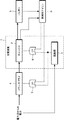
図1は、本技術に係る充電装置1の構成を示すブロック図である。充電装置1は、チャージャ2および起動部3とから構成されている。図1においては、その充電装置1に、パワーサプライ4、バッテリ5、制御用マイコン6、第1OR回路7および第2OR回路8が接続されている。なお、図1において、実線は電力伝送のための電力伝送線を示す。また、破線は制御信号を伝送するための制御線を示す。
<1. Embodiment>
[1-1. Configuration of Charging Device and Power Control Device]
FIG. 1 is a block diagram illustrating a configuration of a
パワーサプライ4は、例えば、DDコンバータなどの電圧変換回路である。パワーサプライ4は特許請求の範囲における電圧変換部に相当する。パワーサプライ4は外部の電力源に接続されており、パワーサプライ4には外部の電力源から電力が供給される。また、パワーサプライ4はチャージャ2に接続されており、外部の電力源からの電力の電圧を所定の電圧に変換してチャージャ2に供給する。
The
外部の電力源としては、電力系統、自然エネルギー発電システムなどがある。電力系統とは、主に電力会社が有する、電力を需要家に供給するための、発電・変電・送電・配電を統合したシステムのことである。 Examples of the external power source include a power system and a natural energy power generation system. The electric power system is a system that integrates power generation / transformation / transmission / distribution, mainly for electric power companies, to supply electric power to consumers.
自然エネルギー発電システムとは、環境負荷が低いいわゆる自然エネルギー、再生可能エネルギーなどと称されるエネルギーを用いた発電設備である。例えば、太陽光、太陽熱、風力、水力、マイクロ水力、潮汐力、波力、水の温度差、海流、バイオマス、地熱、音や振動などのエネルギー、などを利用した発電システムである。また、発電機能を備えるエアロバイク、人が上を歩くことにより発電する仕組みを有する床(発電床などと称される。)など人力で発電を行うものであってもよい。ただし、自然エネルギー発電システムは、上述の発電設備に限られず、環境負荷の低い発電方法を採用したものであればどのようなものであってもよい。 A natural energy power generation system is a power generation facility that uses energy called so-called natural energy, renewable energy, etc., which has a low environmental load. For example, it is a power generation system using sunlight, solar heat, wind power, hydropower, micro hydropower, tidal power, wave power, water temperature difference, ocean current, biomass, geothermal, energy such as sound and vibration. In addition, the power generation may be performed manually, such as an exercise bike having a power generation function, or a floor (called a power generation floor or the like) having a mechanism for generating power by walking on the person. However, the natural energy power generation system is not limited to the above-described power generation facility, and any system that employs a power generation method with a low environmental load may be used.
チャージャ2は、パワーサプライ4およびバッテリ5に接続されており、パワーサプライ4から電力が供給される。そして、チャージャ2は直流交流変換などを行うことによりパワーサプライ4からの電力をバッテリ5に供給する。チャージャ2は例えば、CC(Constant Voltage)回路などからなる定電流バッテリチャージャ、CCCV(Constant Current, Constant Voltage)回路などからなる定電流/定電圧バッテリチャージャである。チャージャ2は、定電流充電、定電流定電圧充電などの充電方式でバッテリ5を充電する。
The
チャージャ2は制御用マイコン6による制御のもと起動および動作する。また、チャージャ2は、制御用マイコン6による制御がなくても、起動部3から供給されるイネーブル信号を受信した場合にも起動し、電力供給を行うことが可能なものである。チャージャは特許請求の範囲における電力供給部に相当するものである。
The
バッテリ5は、電力を蓄えるバッテリセルと、バッテリセルの管理制御を行うセル制御部などから構成されている。バッテリセルを構成する電池としては、リチウムイオン二次電池、リチウムイオンポリマー二次電池、ニッケル水素電池など充放電を行うことができるものであればいかなるものを採用してもよい。 The battery 5 includes a battery cell that stores electric power, a cell control unit that performs management control of the battery cell, and the like. As the battery constituting the battery cell, any battery such as a lithium ion secondary battery, a lithium ion polymer secondary battery, or a nickel metal hydride battery can be used.
セル制御部は、例えば、CPU(Central Processing Unit)、RAM(Random Access Memory)およびROM(Read Only Memory)、バッテリセルの状態(温度、充電量など)の管理を行うセンサなどから構成されている。また、セル制御部は、制御用マイコン6からの要求に応じてバッテリ5の制御に必要な充電量,セル温度,セル電圧などの情報を制御用マイコン6に供給する。
The cell control unit includes, for example, a CPU (Central Processing Unit), a RAM (Random Access Memory) and a ROM (Read Only Memory), a sensor that manages the state (temperature, charge amount, etc.) of the battery cell. . Further, the cell control unit supplies information such as a charge amount, a cell temperature, and a cell voltage necessary for controlling the battery 5 to the
制御用マイコン6は、例えば、マイクロコンピュータにより構成される。なお、制御用マイコン6に代えて、CPU、RAMおよびROMなどにより構成される制御装置を用いるようにしてもよい。制御用マイコン6は、所定のプログラムを実行することにより、充電装置1および充電装置1に接続された各部の制御を行うものである。
The
制御用マイコン6は、第1OR回路7を介してパワーサプライ4と接続されている。制御用マイコン6は、パワーサプライ4を起動させるためのイネーブル信号を供給する。また、制御用マイコン6は、第2OR回路8を介してチャージャ2と接続されている。制御用マイコン6は、チャージャ2を起動させるためのイネーブル信号を供給する。
The
起動部3は、パワーサプライ4およびチャージャ2に対してイネーブル信号を送信することによりをパワーサプライ4およびチャージャ2を起動させる働きを有するものである。起動部3としては、例えば、ユーザにより入力されるスイッチが挙げられる。起動部3は、第1OR回路7を介してパワーサプライ4と接続されている。また、起動部3は第2OR回路8を介してチャージャ2と接続されている。また、起動部3は、外部の電力源と接続され、外部の電力源から電力の供給を受けて動作する。ただし、起動部3がスイッチ、イネーブル信号がオープンドレイン信号であるときには、起動部3にはそれ自身のための電源が不要となる。オープンドレイン信号はワイアードORであり、結線するだけでOR論理演算したことになるものである。
The
第1OR回路7は、制御用マイコン6または起動部3のいずれかからイネーブル信号が供給された場合、それをパワーサプライ4に供給する。また、第2OR回路8は、制御用マイコン6または起動部3のいずれかからイネーブル信号が供給された場合、それをチャージャ2に供給する。
When the enable signal is supplied from either the
起動部3としては、例えば、ユーザが入力可能なボタン、タッチパネルなどが挙げられる。起動部3はユーザからの入力に応じてチャージャ2の電源のオンにするためのイネーブル信号をパワーサプライ4およびチャージャ2に供給する。
Examples of the
起動部3は、ユーザから入力がなされると、所定時間、イネーブル信号を出力する。そのイネーブル信号は、第1OR回路7を介してパワーサプライ4に供給され、また、第2OR回路8を介してチャージャ2に供給される。また、起動部3は、ユーザからの入力がなされている間(例えば、起動部3がボタンを備える場合、ボタンが押下されている間)、イネーブル信号を出力するものでもよい。この場合、ユーザが起動部3に対する入力をやめると、イネーブル信号は停止する。
The
ユーザは、パワーサプライ4およびチャージャ2が起動し、制御用マイコン6に電力が供給されて制御用マイコン6が起動し、制御用マイコン6がパワーサプライ4およびチャージャ2の制御を開始するまでの僅かな時間、起動部3に対して入力を行えばよい。制御用マイコン6はチャージャ2からの電力が制御用マイコン6に供給されるように制御を行う。制御用マイコン6がチャージャ2の制御を開始すれば、起動部3からのイネーブル信号が停止してもチャージャ2は動作し続ける。
The user starts up the
ユーザが充電装置1の電源をオンにしようとしてもバッテリ5の残量がないために充電装置1全体を制御する制御用マイコン6がオンにならない場合、ユーザは起動部3に対して入力を行う。ユーザが起動部3に入力を行うと、イネーブル信号がチャージャ2に供給され、制御用マイコン6からの制御がなくてもパワーサプライ4およびチャージャ2は起動する。
When the user tries to turn on the power of the
起動部3に対する入力は、例えば、充電装置1自体の電源を入れるためのスイッチ(図示せず。)と共に行うなどの手法が考えられる。ただし、起動部3をオンにする方法はこれに限られず、起動部3のみをオンにする方法であってもよい。
For example, the input to the
制御用マイコン6と起動部3は共に第1OR回路7を介してパワーサプライ4と接続されている。また、制御用マイコン6と起動部3は第2OR回路8を介してチャージャ2と接続されている。よって、パワーサプライ4およびチャージャ2は、制御用マイコン6と起動部3のいずれかからイネーブル信号が供給されれば起動することとなる。
Both the
なお、充電装置1におけるfail safe制御はソフトウェア、ハードウェアの両方において実装されている。制御用マイコン6が起動し、通常のチャージャの制御処理を行なっている場合に充電装置1に異常が発生した場合、制御用マイコン6がその異常を検知し、パワーサプライ4にfail safe制御用の制御信号を供給する。これによりパワーサプライ4をディスエーブルとし、その状態を維持して安全性を確保する。
Note that fail safe control in the
一方、制御用マイコン6が起動しておらず、起動部3からのイネーブル信号によりチャージャ2が起動している場合にチャージャ2が異常を検出した場合、チャージャ2自身とパワーサプライ4をディスエーブルとしてその状態を保持する。
On the other hand, when the
以上のようにして充電装置1が構成されている。なお、充電装置1は、外部の電気機器に接続され、その電気機器に電力を供給するようにしてもよい。充電装置1に接続される外部の機器としては、例えば、テレビジョン受像機、オーディオ機器などの電子機器、冷蔵庫、電子レンジ、洗濯機、エアーコンディショナー、パーソナルコンピュータ、コピー機、ファクシミリ、プリンタなどがある。なお、外部機器はこれらの機器に限られず、電力で動作する機器であればどのようなものでもよい。
The charging
図2は、上述の充電装置1の機能を備える電力制御装置20の構成を示すブロック図である。電力制御装置20は、第1絶縁DD11(DDコンバータ)、第2絶縁DD12、チャージャ2、第3絶縁DD13、制御用マイコン6、バッテリ5、起動部3、過電流保護回路14およびロジック回路15とから構成されている。
FIG. 2 is a block diagram showing a configuration of the
第1絶縁DD11は、DDコンバータである。第1絶縁DD11は外部の電力源に接続されており、第1絶縁DD11には外部の電力源から電力が供給される。第1絶縁DD11はチャージャ2に接続されており、外部の電力源からの電力の電圧を所定の電圧に変換してチャージャ2に供給する。第1絶縁DD11は図1におけるパワーサプライ4に相当するものである。
The first insulation DD11 is a DD converter. The first insulation DD11 is connected to an external power source, and power is supplied to the first insulation DD11 from the external power source. The
第2絶縁DD12は、DDコンバータである。第2絶縁DD12は外部の電力源に接続されており、第2絶縁DD12には外部の電力源から電力が供給される。第2絶縁DD12は起動部3に接続されており、外部の電力源からの電力の電圧を所定の電圧に変換して(例えば、外部の電力源から100VACの電力が供給された場合、それを60VDCに変換する。)、起動部3に供給する。また、第2絶縁DD12は、ロジック回路15に接続されており、ロジック回路15にも電力を供給する。
The second insulation DD12 is a DD converter. The second insulation DD12 is connected to an external power source, and power is supplied to the second insulation DD12 from the external power source. The
チャージャ2は、例えば、定電流/定電圧チャージャであり、直流直流変換などを行うことにより第1絶縁DD11から供給された供給された電力をバッテリ5に供給する。チャージャ2は、定電流充電、定電流定電圧充電などの充電方式でバッテリ5を充電する。
The
また、チャージャ2は、電力を第3絶縁DD13にも供給する。第3絶縁DD13は電力の電圧を所定の電圧に変換して(例えば、チャージャ2から60VDCの電力が供給された場合、それを5VDCに変換する。)、制御用マイコン6に供給する。
The
制御用マイコン6は、マイクロコンピュータなどにより構成され、所定のプログラムを実行することにより、充電装置1および充電装置1に接続された各部の制御を行うものである。なお、制御用マイコン6に代えて、CPU、RAMおよびROMなどにより構成される制御装置を用いるようにしてもよい。
The
バッテリ5は、電力を蓄えるバッテリセルと、バッテリセルの管理制御を行うセル制御部などから構成されている。バッテリ5は制御用マイコン6の制御に従って、制御用マイコン6および/または電力制御装置20が接続された外部の電子機器等に電力の供給が可能なものである。なお、制御用マイコン6への電力供給は、チャージャ2から直接第3絶縁DD13を介して行なうようにしてもよい。また、チャージャ2からバッテリ5に電力供給を行い、バッテリ5に蓄えられた電力を第3絶縁DD13を介して制御用マイコン6へ供給することにより制御用マイコン6への電力供給を行うようにしてもよい。
The battery 5 includes a battery cell that stores electric power, a cell control unit that performs management control of the battery cell, and the like. The battery 5 can supply electric power to an external electronic device or the like to which the
起動部3は、上述したように、ユーザからの入力に応じて第1絶縁DD11、チャージャ2の電源のオンにするためのイネーブル信号を供給するものである。また、起動部3は、第2絶縁DD12を介して外部の電力源からの電力が供給されたことを検知した場合に、自動的に所定時間イネーブル信号を供給するものでもよい。チャージャ2と起動部3により充電装置が構成される。
As described above, the
過電流保護回路14は、例えば、IC(Integrated Circuit)などにより構成されている。過電流保護回路14は、電力制御装置20から出力される電力が外部の出力先に必要以上に出力されないように出力電流を制限する回路である。過電流保護回路14はロジック回路15に接続されており、過電流保護を行うための所定の制御信号などを出力する。過電流保護回路14から過電流保護のための制御信号が出力された場合、第1絶縁DD11およびチャージャ2は起動せず、外部に電力が供給されることはない。
The
ロジック回路15は、ICなどにより構成され、論理演算を行うものである。ロジック回路15には、起動部3、制御用マイコン6、過電流保護回路14が接続されている。さらに、ロジック回路15は第1絶縁DD11およびチャージャ2に接続されている。
The
ロジック回路15は、下記の式1に従って論理演算を行う。なお、式1においては、制御用マイコン6からイネーブル信号が供給されることを「A」、起動部3からイネーブル信号が供給されることを「B」、過電流保護回路14が動作していることを「C」としている。
The
[式1]
(A‖B)&&!C
[Formula 1]
(A‖B) &&! C
すなわち、ロジック回路15は、過電流保護回路14が働いておらず、制御用マイコン6または起動部3からイネーブル信号が供給された場合に、そのイネーブル信号を第1絶縁DD11、チャージャ2、第3絶縁DDに供給する。ロジック回路15は、図1における第1OR回路7、第2OR回路8の働きを含んだものであるといえる。一方、過電流保護回路14が働いている場合には、イネーブル信号は、第1絶縁DD11、チャージャ2、第3絶縁DDに供給されない。このようにして、制御用マイコン6または起動部3からのイネーブル信号によって第1絶縁DD11、チャージャ2、第3絶縁DDは起動する。なお、起動部3からのイネーブル信号がオープンドレイン信号であるときは、オープンドレイン信号はワイアードORであり、結線するだけでOR論理演算したことになる。
That is, when the
以上のようにして、充電装置の機能を備える電力制御装置20が構成されている。
As described above, the
[1−2.充電装置および電力制御装置による処理]
次に、充電装置の機能を備える電力制御装置によりなされる処理および動作について説明する。図3は処理および動作の流れを示すフローチャートである。なお、図3に示される処理および動作は、バッテリ5の残量がないまたは僅かであるため、バッテリ5から制御用マイコン6への電力供給が行われず、制御用マイコン6が起動できない状態であることを前提とする。
[1-2. Processing by Charging Device and Power Control Device]
Next, processing and operations performed by the power control device having the function of the charging device will be described. FIG. 3 is a flowchart showing the flow of processing and operation. Note that the processing and operation shown in FIG. 3 are in a state in which the
電力制御装置20は、通常時はバッテリ5に蓄えられた電力により起動および動作し、バッテリ5に蓄えられた電力を制御用マイコン6に供給する。これにより制御用マイコン6は動作することができ、チャージャ2を起動および制御するができる。また、電力制御装置20はバッテリ5に蓄えられた電力を電力制御装置20を構成する各部に供給する共に、外部機器に供給する。
The
しかし、バッテリ5に蓄えられた電力がない場合、または残量が少ない場合、バッテリ5からの電力を制御用マイコン6に供給することができなくなる。そうすると、制御用マイコン6は動作することができず、さらに制御用マイコン6による制御のもと動作するチャージャ2も起動および動作することができなくなる。そうすると、電力源からの電力を用いてバッテリ5を充電することもできなくなり、電力制御装置20が動作することができなくなる。
However, when there is no electric power stored in the battery 5 or when the remaining amount is low, the electric power from the battery 5 cannot be supplied to the
そこで、ユーザが電力制御装置20のバッテリ5の残量が少ないことを確認した場合(例えば、電力制御装置20の電源をオンにしても電力制御装置20が起動しない場合、バッテリ5の残量表示を目視して確認した場合など)、ユーザは手動により起動部3をオンにする。これにより、第1絶縁DD11およびチャージャ2をオンにして電力源からの電力によるバッテリ5への充電を可能にし、さらに制御用マイコン6への電力供給を可能にする。
Therefore, when the user confirms that the remaining amount of the battery 5 of the
まず、ステップS11で、起動部3に対してユーザからの入力が行われたか否かが判定される。入力がない場合、処理は行われない(ステップS11のNo)。一方、ユーザによる起動部3への入力がなされた場合、処理はステップS12に進む(ステップS11のYes)。
First, in step S11, it is determined whether or not an input from the user has been made to the
ユーザから起動部3に対する入力がなされると、ステップS12で起動部3から第1絶縁DD11およびチャージャ2を起動させるためのイネーブル信号が出力される。
When the user inputs to the
次にステップS13で、ロジック回路15は上述した式1に基づく論理演算を行う。ロジック回路15は、制御用マイコン6または起動部3からイネーブル信号が供給され、さらに過電流保護回路14による過電流保護のための制御信号がない場合にイネーブル信号を第1絶縁DD11およびチャージャ2に対して供給する(ステップS13のYes)。
Next, in step S13, the
一方、制御用マイコン6または起動部3からイネーブル信号が供給されても、過電流保護回路14による過電流保護が働いている場合にはイネーブル信号はパワーサプライ4およびチャージャ2には供給されない(ステップS13のNo)。なお、制御用マイコン6または起動部3からイネーブル信号が供給されていない場合には当然、ロジック回路15から第1絶縁DD11およびチャージャ2にイネーブル信号は供給されない(ステップS13のNo)。
On the other hand, even if the enable signal is supplied from the
ロジック回路15から第1絶縁DD11、チャージャ2、第3絶縁DDに対してイネーブル信号が供給された場合、次にステップS14で、イネーブル信号を受けた第1絶縁DD11、チャージャ2、第3絶縁DDが起動する。そして、ステップS15で、第1絶縁DD11、チャージャ2、第3絶縁DDを介して外部の電力源からの電力が制御用マイコン6に供給される。これにより、次にステップS16で制御用マイコン6が起動する。なお、ステップS15では、第1絶縁DD11およびチャージャ2を介して、制御用マイコン6に加えてバッテリ5にも外部の電力源からの電力が供給される。
When an enable signal is supplied from the
次にステップS17で、起動した制御用マイコン6がチャージャ2に所定の制御信号を送信して、チャージャ2の制御を開始する。これ以降、チャージャ2は制御用マイコン6の制御に従い動作する。制御用マイコン6による制御のもとチャージャ2が動作することにより、起動部3からのイネーブル信号が停止してもチャージャ2は動作し続ける。そして、引き続き、第1絶縁DD11およびチャージャ2を介して外部の電力源から電力が制御用マイコン6およびバッテリ5へ供給される。
Next, in step S17, the activated
なお、イネーブル信号の供給は、制御用マイコン6が起動して制御用マイコン6が第1絶縁DD11およびチャージャ2の制御を開始するまで行えば十分である。制御用マイコン6起動後は第1絶縁DD11および制御用マイコン6による制御によりチャージャ2は動作するので、起動部3からのイネーブル信号は不要となるからである。
Note that it is sufficient to supply the enable signal until the
次にステップS18で、制御用マイコン6はバッテリ5の充電量を取得し、バッテリ5の充電量が所定量に達したか否かを判断する。バッテリ5の充電量の取得は、バッテリ5が備えるセル制御部が測定した残量情報を取得することにより行うことができる。また、例えば、バッテリ5に設けられた電圧計、電流計の値を参照することにより取得するようにしてもよい。なお、所定量とは、例えば、満充電である。
Next, in step S18, the
制御用マイコン6が、バッテリ5の充電量が所定量に達したと判定しない場合、すなわち、バッテリ5の充電量が所定量には達していない場合は、所定量に達するまでバッテリ5の充電が行われる(ステップS18のNo)。
If the
一方、ステップS18で、制御用マイコン6がバッテリ5の充電量が所定量に達したと判定した場合、処理はステップS19に進む(ステップS18のYes)。
On the other hand, when the
そして、ステップS19で、制御用マイコン6によって電力供給設定処理が行われる。電力供給設定処理とは、制御用マイコン6、外部機器などへの電力供給をチャージャ2、バッテリ5のどちらからの電力で行うかを設定する処理である。
In step S19, the
例えば、バッテリ5が所定量充電された後、制御用マイコン6は、チャージャ2を停止し、バッテリ5から制御用マイコン6、電力制御装置20の各部、および外部機器へと電力を供給するよう電力制御装置20を制御する。これにより、外部の電力源からの電力供給が停止しても電力制御装置20は自身が有するバッテリ5の電力で動作し、さらに外部へ電力供給を行うことができる。
For example, after the battery 5 is charged by a predetermined amount, the
また、外部機器に供給する電力量が大きい場合には、チャージャ2を動作させ続けて外部の電力源からの電力を外部機器に供給するようにしてもよい。これにより、外部機器に供給する電力量が大きい場合であっても電力の安定的な供給を行うことができる。
Further, when the amount of power supplied to the external device is large, the
このように、本実施の形態においては、バッテリ5の残量がない場合、または残り僅な場合であり、制御用マイコン6が起動せず、制御用マイコン6からの制御では充電装置1が起動しない場合であっても、充電装置1を起動、動作させることができる。これにより、チャージャ2により、制御用マイコン6への電力供給を行うことができる。また、チャージャ2を常時オンの状態にしていなくても制御用マイコン6を起動、動作させることができる。
As described above, in the present embodiment, the battery 5 has no remaining amount or a little remaining, and the
本技術に係る充電装置を備える電力制御装置20のユースケースとしては例えば、無停電電源装置(UPS)が挙げられる。系統電力などの外部電力源からの電力でバッテリを充電し、そのバッテリからの電力を制御用マイコンや外部機器に供給する。これにより、停電などで外部電力源からの電力供給が途絶えた場合でも、継続して制御用マイコンや外部機器に電力供給を行うことができる。
An example of a use case of the
また、本技術は、系統連系においても用いることができる。系統連系とは、例えば、太陽光発電、風力発電などの自然エネルギー発電機の出力を、電力会社などが提供する商用の電力系統と接続し、連系動作させることである。例えば、電気代が安い夜間に系統電力からの電力をバッテリに貯めておき、昼間にそのバッテリからの電力を使用する。 The present technology can also be used in grid interconnection. Grid connection is, for example, connecting the output of a natural energy generator such as solar power generation or wind power generation to a commercial power system provided by a power company or the like, and performing a grid connection operation. For example, the power from the grid power is stored in a battery at night when the electricity bill is cheap, and the power from the battery is used in the daytime.
さらに、外部の電力源が自然エネルギー発電装置である場合に電力供給量の平滑化を図る用途にも用いることができる。自然エネルギー発電は例えば太陽光、風力などにより発電を行うものであり、天候などによって発電量が大きく変動してしまうという問題がある。そこで、本技術に係る充電装置を用いて、自然エネルギー発電装置からの電力をバッテリに貯め、バッテリから制御用マイコンや外部機器に対して電力供給を行うことにより、供給する電力量の平滑化を図ることができる。 Furthermore, when the external power source is a natural energy power generation device, it can also be used for applications in which the amount of power supply is smoothed. Natural energy power generation is, for example, power generation using sunlight, wind power, etc., and there is a problem that the amount of power generation varies greatly depending on the weather. Therefore, using the charging device according to the present technology, the electric power from the natural energy power generation device is stored in the battery, and the electric power is supplied from the battery to the control microcomputer and the external device, thereby smoothing the amount of electric power to be supplied. Can be planned.
<3.変形例>
以上、本技術の一実施の形態について具体的に説明したが、本技術は上述の実施形態に限定されるものではなく、本技術の技術的思想に基づく各種の変形が可能である。
<3. Modification>
Although one embodiment of the present technology has been specifically described above, the present technology is not limited to the above-described embodiment, and various modifications based on the technical idea of the present technology are possible.
上述した実施の形態では過電流保護回路を含んだ構成について説明したが、過電流保護回路は必須の構成ではない。過電流保護回路がなくても本発明は成り立つものである。 In the above-described embodiment, the configuration including the overcurrent protection circuit has been described. However, the overcurrent protection circuit is not an essential configuration. The present invention can be realized without an overcurrent protection circuit.
次に、本技術に係る電力制御装置を適用した電動車両および蓄電装置などの機器について説明する。 Next, devices such as an electric vehicle and a power storage device to which the power control device according to the present technology is applied will be described.
電動車両としては鉄道車両、ゴルフカート、電動カート、電気自動車(ハイブリッド自動車を含む)などが挙げられる。 Examples of the electric vehicle include a railway vehicle, a golf cart, an electric cart, and an electric vehicle (including a hybrid vehicle).
蓄電装置としては、住宅をはじめとする建築物用または発電設備用の電力貯蔵用電源などが挙げられる。 Examples of the power storage device include a power storage power source for buildings such as houses or power generation facilities.
以下では、上述した適用例のうち、本技術の充電装置の機能を備える電力制御装置20を適用した蓄電装置を用いた蓄電システムの具体例を説明する。
Below, the specific example of the electrical storage system using the electrical storage apparatus to which the electric
この蓄電システムは、例えば下記の様な構成が挙げられる。第1の蓄電システムは、再生可能エネルギーから発電を行う発電装置によって蓄電装置が充電される蓄電システムである。第2の蓄電システムは、蓄電装置を有し、蓄電装置に接続される電子機器に電力を供給する蓄電システムである。第3の蓄電システムは、蓄電装置から、電力の供給を受ける電子機器である。これらの蓄電システムは、外部の電力供給網と協働して電力の効率的な供給を図るシステムとして実施される。 This power storage system has the following configuration, for example. The first power storage system is a power storage system in which a power storage device is charged by a power generation device that generates power from renewable energy. The second power storage system is a power storage system that includes a power storage device and supplies power to an electronic device connected to the power storage device. The third power storage system is an electronic device that is supplied with power from the power storage device. These power storage systems are implemented as a system for efficiently supplying power in cooperation with an external power supply network.
さらに、第4の蓄電システムは、蓄電装置から電力の供給を受けて車両の駆動力に変換する変換装置と、蓄電装置に関する情報に基づいて車両制御に関する情報処理を行なう制御装置とを有する電動車両である。第5の蓄電システムは、他の機器とネットワークを介して信号を送受信する電力情報送受信部とを備え、送受信部が受信した情報に基づき、上述した蓄電装置の充放電制御を行う電力システムである。第6の蓄電システムは、上述した蓄電装置から、電力の供給を受け、または発電装置または電力網から蓄電装置に電力を供給する電力システムである。以下、蓄電システムについて説明する。 Furthermore, the fourth power storage system includes an electric vehicle having a conversion device that receives power supplied from the power storage device and converts the power into a driving force of the vehicle, and a control device that performs information processing related to vehicle control based on information related to the power storage device. It is. The fifth power storage system is a power system that includes a power information transmission / reception unit that transmits / receives signals to / from other devices via a network, and performs charge / discharge control of the power storage device described above based on information received by the transmission / reception unit. . The sixth power storage system is a power system that receives power from the power storage device described above or supplies power from the power generation device or the power network to the power storage device. Hereinafter, the power storage system will be described.
(3−1)応用例としての住宅における蓄電システム
本技術に係る電力制御装置を用いた蓄電装置を住宅用の蓄電システムに適用した例について、図4を参照して説明する。蓄電装置103は、バッテリを備え、さらに電力制御装置20の機能を備えるものである。
(3-1) Residential Power Storage System as an Application Example An example in which a power storage device using a power control device according to the present technology is applied to a residential power storage system will be described with reference to FIG. The
例えば住宅101用の蓄電システム100においては、火力発電102a、原子力発電102b、水力発電102cなどの集中型電力系統102から電力網109、情報網112、パワーハブ108などを介し、電力が蓄電装置103に供給される。これと共に、家庭内発電装置104などの独立電源から電力が蓄電装置103に供給される。蓄電装置103に供給された電力が蓄電される。蓄電装置103を使用して、住宅101で使用する電力が給電される。住宅101に限らずビルに関しても同様の蓄電システムを使用できる。
For example, in the power storage system 100 for the house 101, power is supplied to the
住宅101には、家庭内発電装置104、電力消費装置105、蓄電装置103、各装置を制御する制御装置110、各種情報を取得するセンサ111が設けられている。電力制御装置20は蓄電装置103と接続され、各装置は、電力網109および情報網112によって接続されている。家庭内発電装置104として、太陽電池、燃料電池などが利用され、発電した電力が電力消費装置105および/または蓄電装置103に供給される。電力消費装置105は、冷蔵庫105a、空調装置105b、テレビジョン受信機105c、風呂105dなどである。さらに、電力消費装置105には、電動車両106が含まれる。電動車両106は、電気自動車106a、ハイブリッドカー106b、電気バイク106cである。
The house 101 is provided with a home power generation device 104, a
蓄電装置103にはバッテリが設けられている。バッテリは、例えば上述したリチウムイオン二次電池によって構成されていてもよい。電力網109は、直流給電、交流給電、非接触給電の何れか一つまたは複数を組み合わせてもよい。
The
各種のセンサ111は、例えば人感センサ、照度センサ、物体検知センサ、消費電力センサ、振動センサ、接触センサ、温度センサ、赤外線センサなどである。各種のセンサ111により取得された情報は、制御装置110に送信される。センサ111からの情報によって、気象の状態、人の状態などが把握されて電力消費装置105を自動的に制御してエネルギー消費を最小とすることができる。さらに、制御装置110は、住宅101に関する情報をインターネットを介して外部の電力会社などに送信することができる。
The
パワーハブ108によって、電力線の分岐、直流交流変換などの処理がなされる。制御装置110と接続される情報網112の通信方式としては、UART(Universal Asynchronous Receiver-Transceiver:非同期シリアル通信用送受信回路)などの通信インターフェースを使う方法、Bluetooth(Bluetooth SIGの登録商標)、ZigBee、Wi−Fiなどの無線通信規格によるセンサーネットワークを利用する方法がある。Bluetooth方式は、マルチメディア通信に適用され、一対多接続の通信を行うことができる。ZigBeeは、IEEE(Institute of Electrical and Electronics Engineers)802.15.4の物理層を使用するものである。IEEE802.15.4は、PAN(Personal Area Network)またはW(Wireless)PANと呼ばれる短距離無線ネットワーク規格の名称である。
The
制御装置110は、外部のサーバ113と接続されている。このサーバ113は、住宅101、電力会社、サービスプロバイダーの何れかによって管理されていてもよい。サーバ113が送受信する情報は、たとえば、消費電力情報、生活パターン情報、電力料金、天気情報、天災情報、電力取引に関する情報である。これらの情報は、家庭内の電力消費装置(たとえばテレビジョン受信機)から送受信してもよいが、家庭外の装置(たとえば、携帯電話機など)から送受信してもよい。これらの情報は、表示機能を持つ機器、たとえば、テレビジョン受信機、携帯電話機、PDA(Personal Digital Assistants)などに、表示されてもよい。
The
各部を制御する制御装置110は、CPU、RAM、ROMなどで構成され、この例では、蓄電装置103に格納されている。制御装置110は、蓄電装置103、家庭内発電装置104、電力消費装置105、各種のセンサ111、サーバ113と情報網112により接続され、例えば、商用電力の使用量と、発電量とを調整する機能を有している。なお、その他にも、電力市場で電力取引を行う機能などを備えていてもよい。
A
以上のように、電力が火力102a、原子力102b、水力102cなどの集中型電力系統102のみならず、家庭内発電装置104(太陽光発電、風力発電)の発電電力を蓄電装置103に蓄えることができる。したがって、家庭内発電装置104の発電電力が変動しても、外部に送出する電力量を一定にしたり、または、必要なだけ放電するといった制御を行うことができる。例えば、太陽光発電で得られた電力を蓄電装置103に蓄えると共に、夜間は料金が安い深夜電力を蓄電装置103に蓄え、昼間の料金が高い時間帯に蓄電装置103によって蓄電した電力を放電して利用するといった使い方もできる。
As described above, the electric power can be stored not only in the
なお、蓄電システム100は、集合住宅における複数の家庭を対象として用いられてもよいし、複数の戸建て住宅を対象として用いられてもよい。 The power storage system 100 may be used for a plurality of homes in an apartment house, or may be used for a plurality of detached houses.
(3−2)応用例としての車両における蓄電システム
本技術を車両用の蓄電システムに適用した例について、図5を参照して説明する。図5に、本技術が適用されるシリーズハイブリッドシステムを採用するハイブリッド車両の構成の一例を概略的に示す。シリーズハイブリッドシステムはエンジンで動かす発電機で発電された電力、あるいはそれをバッテリに一旦貯めておいた電力を用いて、電力駆動力変換装置で走行する車である。
(3-2) Power Storage System in Vehicle as Application Example An example in which the present technology is applied to a power storage system for a vehicle will be described with reference to FIG. FIG. 5 schematically shows an example of the configuration of a hybrid vehicle that employs a series hybrid system to which the present technology is applied. A series hybrid system is a vehicle that runs on an electric power driving force conversion device using electric power generated by a generator driven by an engine or electric power that is temporarily stored in a battery.
このハイブリッド車両200には、エンジン201、発電機202、電力駆動力変換装置203、駆動輪204a、駆動輪204b、車輪205a、車輪205b、電力制御装置20、車両制御装置209、各種センサ210、充電口211が搭載されている。電力制御装置20には、バッテリ208が設けられている。バッテリ208が、図1に示される電力制御装置20におけるバッテリに相当する。
The
ハイブリッド車両200は、電力駆動力変換装置203を動力源として走行する。電力駆動力変換装置203の一例は、モータである。バッテリ208の電力によって電力駆動力変換装置203が作動し、この電力駆動力変換装置203の回転力が駆動輪204a、204bに伝達される。なお、必要な個所に直流−交流(DC−AC)あるいは逆変換(AC−DC変換)を用いることによって、電力駆動力変換装置203が交流モータでも直流モータでも適用可能である。各種センサ210は、車両制御装置209を介してエンジン回転数を制御したり、図示しないスロットルバルブの開度(スロットル開度)を制御したりする。各種センサ210には、速度センサ、加速度センサ、エンジン回転数センサなどが含まれる。
The
エンジン201の回転力は発電機202に伝えられ、その回転力によって発電機202により生成された電力をバッテリ208に蓄積することが可能である。
The rotational force of the
図示しない制動機構によりハイブリッド車両200が減速すると、その減速時の抵抗力が電力駆動力変換装置203に回転力として加わり、この回転力によって電力駆動力変換装置203により生成された回生電力がバッテリ208に蓄積される。
When the
バッテリ208は、ハイブリッド車両200の外部の電源に接続されることで、その外部電源から充電口211を入力口として電力供給を受け、受けた電力を蓄積することも可能である。
The
図示しないが、電池に関する情報に基づいて車両制御に関する情報処理を行う情報処理装置を備えていてもよい。このような情報処理装置としては、例えば、電池の残量に関する情報に基づき、電池残量表示を行う情報処理装置などがある。 Although not shown, an information processing apparatus that performs information processing related to vehicle control based on information related to the battery may be provided. As such an information processing apparatus, for example, there is an information processing apparatus that displays a remaining battery level based on information on the remaining battery level.
なお、以上は、エンジンで動かす発電機で発電された電力、或いはそれをバッテリに一旦貯めておいた電力を用いて、モータで走行するシリーズハイブリッド車を例として説明した。しかしながら、エンジンとモータの出力がいずれも駆動源とし、エンジンのみで走行、モータのみで走行、エンジンとモータ走行という3つの方式を適宜切り替えて使用するパラレルハイブリッド車に対しても本技術は有効に適用可能である。さらに、エンジンを用いず駆動モータのみによる駆動で走行する所謂、電動車両に対しても本技術は有効に適用可能である。 In addition, the above demonstrated as an example the series hybrid vehicle which drive | works with a motor using the electric power generated with the generator driven by an engine, or the electric power once stored in the battery. However, the present technology is also effective for a parallel hybrid vehicle in which the engine and motor outputs are both driving sources, and the system is switched between the three modes of driving with only the engine, driving with the motor, and engine and motor. Applicable. Furthermore, the present technology can be effectively applied to a so-called electric vehicle that travels only by a drive motor without using an engine.
また、本技術は以下のような構成も取ることができる。 In addition, the present technology can take the following configurations.
(1)電力源からの電力を外部に供給する電力供給部と、
該電力供給部を起動させる制御部が起動しない場合に、前記電力供給部を起動させる起動部と
を備える充電装置。
(1) a power supply unit for supplying power from a power source to the outside;
A charging device comprising: an activation unit that activates the power supply unit when a control unit that activates the power supply unit does not activate.
(2)前記電力供給部は、前記制御部または前記起動部のいずれかからイネーブル信号を受信することにより起動する
前記(1)に記載の充電装置。
(2) The charging device according to (1), wherein the power supply unit is activated by receiving an enable signal from either the control unit or the activation unit.
(3)前記起動部または前記制御部からのイネーブル信号を電力供給部に出力するOR回路をさらに備える
前記(1)または(2)に記載の充電装置。
(3) The charging device according to (1) or (2), further including an OR circuit that outputs an enable signal from the activation unit or the control unit to a power supply unit.
(4)前記起動部は、ユーザからの入力に応じて前記電力供給部を起動させる
前記(1)から(3)のいずれかに記載の充電装置。
(4) The charging device according to any one of (1) to (3), wherein the activation unit activates the power supply unit in response to an input from a user.
(5)前記起動部は、前記電力源からの電力の供給に応じて所定時間イネーブル信号を供給することにより前記電力供給部を起動させる
前記(1)から(4)のいずれかに記載の充電装置。
(5) The charging according to any one of (1) to (4), wherein the activation unit activates the power supply unit by supplying an enable signal for a predetermined time according to supply of power from the power source. apparatus.
(6)前記電力源からの電力の電圧を所定の電圧に変換して前記電力供給部に供給する電圧変換部をさらに備える
前記(1)から(5)のいずれかに記載の充電装置。
(6) The charging device according to any one of (1) to (5), further including a voltage conversion unit that converts a voltage of power from the power source into a predetermined voltage and supplies the voltage to the power supply unit.
(7)電力源からの電力を外部に供給する電力供給部を、該電力供給部を起動させる制御部が起動しない場合に起動させる
充電装置の制御方法。
(7) A method for controlling a charging device that activates a power supply unit that supplies power from a power source to the outside when the control unit that activates the power supply unit does not activate.
(8)電力源からの電力を外部に供給する電力供給部と、
該電力供給部を起動させる制御部が起動しない場合に、前記電力供給部を起動させる起動部と
を備える充電装置と、
前記電力供給部から電力の供給を受けて車両の駆動力に変換する変換装置と、
前記電力供給部に関する情報に基づいて車両制御に関する情報処理を行う制御装置とを有する
電動車両。
(8) a power supply unit that supplies power from a power source to the outside;
A charging device including an activation unit that activates the power supply unit when the control unit that activates the power supply unit does not activate;
A conversion device that receives supply of electric power from the electric power supply unit and converts it into driving force of a vehicle;
An electric vehicle comprising: a control device that performs information processing related to vehicle control based on information related to the power supply unit.
(9)電力源からの電力を外部に供給する電力供給部と、
該電力供給部を起動させる制御部が起動しない場合に、前記電力供給部を起動させる起動部と
を備える充電装置を備え、
前記電力供給部に接続される電子機器に電力を供給する蓄電装置。
(9) a power supply unit that supplies power from a power source to the outside;
A charging device comprising: an activation unit that activates the power supply unit when the control unit that activates the power supply unit does not activate;
A power storage device that supplies power to an electronic device connected to the power supply unit.
(10)電力源からの電力を外部に供給する電力供給部と、
該電力供給部を起動させる制御部が起動しない場合に、前記電力供給部を起動させる起動部と
を備える充電装置を備え、
電池から電力の供給を受け、または、発電装置もしくは電力網から前記電池に電力が供給される
電力システム。
(10) a power supply unit that supplies power from a power source to the outside;
A charging device comprising: an activation unit that activates the power supply unit when the control unit that activates the power supply unit does not activate;
An electric power system which receives supply of electric power from a battery or supplies electric power to the battery from a power generation device or an electric power network.
1・・・充電装置
2・・・チャージャ
3・・・起動部
5・・・バッテリ
6・・・制御用マイコン
DESCRIPTION OF
Claims (8)
該電力供給部を起動させる制御部が起動しない場合に、前記電力供給部を起動させる起動部と、
前記電力源からの電力の電圧を所定の電圧に変換して前記電力供給部に供給する電圧変換部とを備え、
前記電力供給部は、前記制御部または前記起動部のいずれかからイネーブル信号を受信することにより起動し、
前記制御部が起動し、該制御部による通常の前記電力供給部の制御処理を行っている場合に異常が発生すると、前記制御部が異常を検知して前記電圧変換部をディスエーブルとし、
前記制御部が起動しておらず、前記起動部からのイネーブル信号により前記電力供給部が起動している場合に前記電力供給部が異常を検知した場合、該電力供給部と前記電圧変換部をディスエーブルとする
充電装置。 A power supply unit for supplying power from a power source to the outside;
An activation unit that activates the power supply unit when the control unit that activates the power supply unit does not activate; and
A voltage conversion unit that converts a voltage of power from the power source into a predetermined voltage and supplies the voltage to the power supply unit;
The power supply unit is activated by receiving an enable signal from either the control unit or the activation unit,
When an abnormality occurs when the control unit is activated and the control unit performs normal control of the power supply unit , the control unit detects the abnormality and disables the voltage conversion unit.
When the power supply unit detects an abnormality when the control unit is not activated and the power supply unit is activated by an enable signal from the activation unit , the power supply unit and the voltage conversion unit are Disabling charging device.
請求項1に記載の充電装置。 The charging device according to claim 1, further comprising an OR circuit that outputs an enable signal from the activation unit or the control unit to a power supply unit.
請求項1または2に記載の充電装置。 The charging device according to claim 1, wherein the activation unit activates the power supply unit in response to an input from a user.
請求項1から3のいずれかに記載の充電装置。 The charging device according to any one of claims 1 to 3, wherein the activation unit activates the power supply unit by supplying an enable signal for a predetermined time in accordance with supply of power from the power source.
該電力供給部を起動させる制御部が起動しない場合に、前記電力供給部を起動させる起動部と、
前記電力源からの電力の電圧を所定の電圧に変換して前記電力供給部に供給する電圧変換部とを備える充電装置の制御方法であって、
前記電力供給部は、前記制御部または前記起動部のいずれかからイネーブル信号を受信することにより起動し、
前記制御部が起動し、該制御部による通常の前記電力供給部の制御処理を行っている場合に異常が発生すると、前記制御部が異常を検知して前記電圧変換部をディスエーブルとし、
前記制御部が起動しておらず、前記起動部からのイネーブル信号により前記電力供給部が起動している場合に前記電力供給部が異常を検知した場合、該電力供給部と前記電圧変換部をディスエーブルとする
充電装置の制御方法。 A power supply unit for supplying power from a power source to the outside;
An activation unit that activates the power supply unit when the control unit that activates the power supply unit does not activate; and
A method for controlling a charging device comprising: a voltage conversion unit that converts a voltage of power from the power source into a predetermined voltage and supplies the voltage to the power supply unit;
The power supply unit is activated by receiving an enable signal from either the control unit or the activation unit,
When an abnormality occurs when the control unit is activated and the control unit performs normal control of the power supply unit , the control unit detects the abnormality and disables the voltage conversion unit.
When the power supply unit detects an abnormality when the control unit is not activated and the power supply unit is activated by an enable signal from the activation unit , the power supply unit and the voltage conversion unit are A method for controlling the charging device to be disabled.
該電力供給部を起動させる制御部が起動しない場合に、前記電力供給部を起動させる起動部と、
前記電力源からの電力の電圧を所定の電圧に変換して前記電力供給部に供給する電圧変換部とを備え、
前記電力供給部は、前記制御部または前記起動部のいずれかからイネーブル信号を受信することにより起動し、
前記制御部が起動し、該制御部による通常の前記電力供給部の制御処理を行っている場合に異常が発生すると、前記制御部が異常を検知して前記電圧変換部をディスエーブルとし、
前記制御部が起動しておらず、前記起動部からのイネーブル信号により前記電力供給部が起動している場合に前記電力供給部が異常を検知した場合、該電力供給部と前記電圧変換部をディスエーブルとする
充電装置と、
前記電力供給部から電力の供給を受けて車両の駆動力に変換する変換装置と、
前記電力供給部に関する情報に基づいて車両制御に関する情報処理を行う制御装置と
を有する
電動車両。 A power supply unit for supplying power from a power source to the outside;
An activation unit that activates the power supply unit when the control unit that activates the power supply unit does not activate; and
A voltage conversion unit that converts a voltage of power from the power source into a predetermined voltage and supplies the voltage to the power supply unit;
The power supply unit is activated by receiving an enable signal from either the control unit or the activation unit,
When an abnormality occurs when the control unit is activated and the control unit performs normal control of the power supply unit , the control unit detects the abnormality and disables the voltage conversion unit.
When the power supply unit detects an abnormality when the control unit is not activated and the power supply unit is activated by an enable signal from the activation unit , the power supply unit and the voltage conversion unit are A charging device to be disabled;
A conversion device that receives supply of electric power from the electric power supply unit and converts it into driving force of a vehicle;
An electric vehicle comprising: a control device that performs information processing related to vehicle control based on information related to the power supply unit.
該電力供給部を起動させる制御部が起動しない場合に、前記電力供給部を起動させる起動部と、
前記電力源からの電力の電圧を所定の電圧に変換して前記電力供給部に供給する電圧変換部とを備え、
前記電力供給部は、前記制御部または前記起動部のいずれかからイネーブル信号を受信することにより起動し、
前記制御部が起動し、該制御部による通常の前記電力供給部の制御処理を行っている場合に異常が発生すると、前記制御部が異常を検知して前記電圧変換部をディスエーブルとし、
前記制御部が起動しておらず、前記起動部からのイネーブル信号により前記電力供給部が起動している場合に前記電力供給部が異常を検知した場合、該電力供給部と前記電圧変換部をディスエーブルとする
充電装置を備え、
前記電力供給部に接続される電子機器に電力を供給する蓄電装置。 A power supply unit for supplying power from a power source to the outside;
An activation unit that activates the power supply unit when the control unit that activates the power supply unit does not activate; and
A voltage conversion unit that converts a voltage of power from the power source into a predetermined voltage and supplies the voltage to the power supply unit;
The power supply unit is activated by receiving an enable signal from either the control unit or the activation unit,
When an abnormality occurs when the control unit is activated and the control unit performs normal control of the power supply unit , the control unit detects the abnormality and disables the voltage conversion unit.
When the power supply unit detects an abnormality when the control unit is not activated and the power supply unit is activated by an enable signal from the activation unit , the power supply unit and the voltage conversion unit are It has a charging device that disables it,
A power storage device that supplies power to an electronic device connected to the power supply unit.
該電力供給部を起動させる制御部が起動しない場合に、前記電力供給部を起動させる起動部と、
前記電力源からの電力の電圧を所定の電圧に変換して前記電力供給部に供給する電圧変換部とを備え、
前記電力供給部は、前記制御部または前記起動部のいずれかからイネーブル信号を受信することにより起動し、
前記制御部が起動し、該制御部による通常の前記電力供給部の制御処理を行っている場合に異常が発生すると、前記制御部が異常を検知して前記電圧変換部をディスエーブルとし、
前記制御部が起動しておらず、前記起動部からのイネーブル信号により前記電力供給部が起動している場合に前記電力供給部が異常を検知した場合、該電力供給部と前記電圧変換部をディスエーブルとする
充電装置を備え、
電池から電力の供給を受け、または、発電装置もしくは電力網から前記電池に電力が供給される
電力システム。 A power supply unit for supplying power from a power source to the outside;
An activation unit that activates the power supply unit when the control unit that activates the power supply unit does not activate; and
A voltage conversion unit that converts a voltage of power from the power source into a predetermined voltage and supplies the voltage to the power supply unit;
The power supply unit is activated by receiving an enable signal from either the control unit or the activation unit,
When an abnormality occurs when the control unit is activated and the control unit performs normal control of the power supply unit , the control unit detects the abnormality and disables the voltage conversion unit.
When the power supply unit detects an abnormality when the control unit is not activated and the power supply unit is activated by an enable signal from the activation unit , the power supply unit and the voltage conversion unit are It has a charging device that disables it,
An electric power system which receives supply of electric power from a battery or supplies electric power to the battery from a power generation device or an electric power network.
Priority Applications (4)
| Application Number | Priority Date | Filing Date | Title |
|---|---|---|---|
| JP2012093677A JP6010995B2 (en) | 2012-04-17 | 2012-04-17 | Charging device, charging device control method, electric vehicle, power storage device, and power system |
| EP13158593.7A EP2653338A3 (en) | 2012-04-17 | 2013-03-11 | Charging device, control method of charging device, electric-powered vehicle, energy storage device and power system |
| US13/859,790 US20130271078A1 (en) | 2012-04-17 | 2013-04-10 | Charging device, control method of charging device, electric-powered vehicle, energy storage device and power system |
| CN201310122313.XA CN103378631B (en) | 2012-04-17 | 2013-04-10 | Charging device, control method of the charging device, electric-powered vehicle, energy storage device and power system |
Applications Claiming Priority (1)
| Application Number | Priority Date | Filing Date | Title |
|---|---|---|---|
| JP2012093677A JP6010995B2 (en) | 2012-04-17 | 2012-04-17 | Charging device, charging device control method, electric vehicle, power storage device, and power system |
Publications (3)
| Publication Number | Publication Date |
|---|---|
| JP2013223349A JP2013223349A (en) | 2013-10-28 |
| JP2013223349A5 JP2013223349A5 (en) | 2015-04-02 |
| JP6010995B2 true JP6010995B2 (en) | 2016-10-19 |
Family
ID=47833005
Family Applications (1)
| Application Number | Title | Priority Date | Filing Date |
|---|---|---|---|
| JP2012093677A Expired - Fee Related JP6010995B2 (en) | 2012-04-17 | 2012-04-17 | Charging device, charging device control method, electric vehicle, power storage device, and power system |
Country Status (4)
| Country | Link |
|---|---|
| US (1) | US20130271078A1 (en) |
| EP (1) | EP2653338A3 (en) |
| JP (1) | JP6010995B2 (en) |
| CN (1) | CN103378631B (en) |
Families Citing this family (6)
| Publication number | Priority date | Publication date | Assignee | Title |
|---|---|---|---|---|
| CN105409088A (en) * | 2013-06-13 | 2016-03-16 | 上海火亮新能源科技有限公司 | Battery energy storage system and controlling method |
| US20150048778A1 (en) * | 2013-08-13 | 2015-02-19 | Quantum Group, Inc. | Modular battery charging station and generator |
| JP2015089320A (en) * | 2013-11-01 | 2015-05-07 | ソニー株式会社 | Power storage system and control method for the same |
| US10797490B2 (en) * | 2014-03-26 | 2020-10-06 | Intersil Americas LLC | Battery charge system with transition control that protects adapter components when transitioning from battery mode to adapter mode |
| WO2016114116A1 (en) * | 2015-01-16 | 2016-07-21 | パナソニックIpマネジメント株式会社 | Storage-battery control system |
| CN110745021B (en) * | 2019-11-27 | 2021-05-18 | 上海玖行能源科技有限公司 | Control system and control method for electronic lock of charging gun of electric automobile |
Family Cites Families (20)
| Publication number | Priority date | Publication date | Assignee | Title |
|---|---|---|---|---|
| JPH0241628A (en) * | 1988-07-30 | 1990-02-09 | Toshiba Corp | Charging equipment for battery |
| IL136235A0 (en) * | 1997-11-17 | 2001-05-20 | Lifestyle Technologies | Universal power supply |
| KR100447676B1 (en) * | 2002-12-11 | 2004-09-08 | 주식회사 팬택앤큐리텔 | Circuit for preventing handset off and method thereof |
| US7339347B2 (en) * | 2003-08-11 | 2008-03-04 | Reserve Power Cell, Llc | Apparatus and method for reliably supplying electrical energy to an electrical system |
| JP4471314B2 (en) * | 2004-11-30 | 2010-06-02 | 株式会社オートネットワーク技術研究所 | Power supply control device |
| JP4487803B2 (en) | 2005-02-28 | 2010-06-23 | ソニー株式会社 | Uninterruptible power supply and processing equipment |
| US7570015B2 (en) * | 2007-03-09 | 2009-08-04 | International Business Machines Corporation | Conditional battery charging system |
| JP5162188B2 (en) * | 2007-08-31 | 2013-03-13 | 京セラ株式会社 | Mobile communication terminal, startup method, and boot program |
| US8531162B2 (en) * | 2008-06-16 | 2013-09-10 | International Business Machines Corporation | Network based energy preference service for managing electric vehicle charging preferences |
| US9853488B2 (en) * | 2008-07-11 | 2017-12-26 | Charge Fusion Technologies, Llc | Systems and methods for electric vehicle charging and power management |
| JP4438887B1 (en) * | 2008-09-26 | 2010-03-24 | トヨタ自動車株式会社 | Electric vehicle and charging control method for electric vehicle |
| CN102421630B (en) * | 2009-05-08 | 2014-05-21 | 丰田自动车株式会社 | Power supply system and vehicle equipped with power supply system |
| US20100292857A1 (en) * | 2009-05-18 | 2010-11-18 | Consolidated Edison Company Of New York, Inc. | Electrical network command and control system and method of operation |
| WO2011087860A2 (en) * | 2009-12-22 | 2011-07-21 | G2 Llc | Battery charging and management systems and related methods |
| WO2011095132A1 (en) * | 2010-02-05 | 2011-08-11 | 苏州宝时得电动工具有限公司 | Charger |
| JP5418301B2 (en) * | 2010-02-26 | 2014-02-19 | 株式会社デンソー | In-vehicle charging controller |
| KR101146378B1 (en) * | 2010-06-09 | 2012-05-17 | 삼성에스디아이 주식회사 | Charging battery pack and system thererwith |
| JP5126297B2 (en) * | 2010-06-21 | 2013-01-23 | 三菱自動車工業株式会社 | Power management system and in-vehicle power management device |
| US8849499B2 (en) * | 2011-01-06 | 2014-09-30 | Ford Global Technologies, Llc | Methods and systems for monitoring a vehicle's energy source |
| US9379559B2 (en) * | 2012-02-03 | 2016-06-28 | International Business Machines Corporation | System and method of charging a vehicle using a dynamic power grid, and system and method of managing power consumption in the vehicle |
-
2012
- 2012-04-17 JP JP2012093677A patent/JP6010995B2/en not_active Expired - Fee Related
-
2013
- 2013-03-11 EP EP13158593.7A patent/EP2653338A3/en not_active Withdrawn
- 2013-04-10 US US13/859,790 patent/US20130271078A1/en not_active Abandoned
- 2013-04-10 CN CN201310122313.XA patent/CN103378631B/en not_active Expired - Fee Related
Also Published As
| Publication number | Publication date |
|---|---|
| EP2653338A3 (en) | 2017-01-25 |
| CN103378631B (en) | 2017-05-10 |
| EP2653338A2 (en) | 2013-10-23 |
| CN103378631A (en) | 2013-10-30 |
| JP2013223349A (en) | 2013-10-28 |
| US20130271078A1 (en) | 2013-10-17 |
Similar Documents
| Publication | Publication Date | Title |
|---|---|---|
| JP5747491B2 (en) | Electric storage system, electric vehicle and electric power system | |
| JP6028499B2 (en) | Power supply | |
| JP6010995B2 (en) | Charging device, charging device control method, electric vehicle, power storage device, and power system | |
| JP5071545B2 (en) | Electricity supply and demand system | |
| JP5742524B2 (en) | Control device, power storage system, electronic device, electric vehicle, and power system | |
| US9906025B2 (en) | Electric power supply apparatus and system | |
| CN105262134B (en) | Household nano-network system and community-level micro-grid system | |
| WO2011055196A1 (en) | Power distribution system | |
| CA2916170C (en) | Electricity storage device, electricity storage system, and method for controlling electricity storage device | |
| JP2012123637A (en) | Charge controller, control method of charge controller, charge/discharge controller, control method of charge/discharge controller, control program, and recording medium | |
| JP5220078B2 (en) | In-vehicle charging / discharging device | |
| WO2018078975A1 (en) | Power supply device and power storage device | |
| JP6107550B2 (en) | In-vehicle charger | |
| JP6313197B2 (en) | Charge / discharge system | |
| JP2013211947A (en) | Power control device, power control method, electric vehicle, power storage device and power system | |
| CN205070461U (en) | Household nano-network system and community-level micro-grid system | |
| JP7494874B2 (en) | Power Supply System | |
| JP2013005479A (en) | Information output system | |
| JP2024060803A (en) | Power system, server, and control method of power |
Legal Events
| Date | Code | Title | Description |
|---|---|---|---|
| A521 | Request for written amendment filed |
Free format text: JAPANESE INTERMEDIATE CODE: A523 Effective date: 20150210 |
|
| A621 | Written request for application examination |
Free format text: JAPANESE INTERMEDIATE CODE: A621 Effective date: 20150210 |
|
| A977 | Report on retrieval |
Free format text: JAPANESE INTERMEDIATE CODE: A971007 Effective date: 20151109 |
|
| A131 | Notification of reasons for refusal |
Free format text: JAPANESE INTERMEDIATE CODE: A131 Effective date: 20151117 |
|
| A521 | Request for written amendment filed |
Free format text: JAPANESE INTERMEDIATE CODE: A523 Effective date: 20160108 |
|
| A131 | Notification of reasons for refusal |
Free format text: JAPANESE INTERMEDIATE CODE: A131 Effective date: 20160524 |
|
| A521 | Request for written amendment filed |
Free format text: JAPANESE INTERMEDIATE CODE: A523 Effective date: 20160628 |
|
| TRDD | Decision of grant or rejection written | ||
| A01 | Written decision to grant a patent or to grant a registration (utility model) |
Free format text: JAPANESE INTERMEDIATE CODE: A01 Effective date: 20160823 |
|
| A61 | First payment of annual fees (during grant procedure) |
Free format text: JAPANESE INTERMEDIATE CODE: A61 Effective date: 20160905 |
|
| R151 | Written notification of patent or utility model registration |
Ref document number: 6010995 Country of ref document: JP Free format text: JAPANESE INTERMEDIATE CODE: R151 |
|
| R250 | Receipt of annual fees |
Free format text: JAPANESE INTERMEDIATE CODE: R250 |
|
| R250 | Receipt of annual fees |
Free format text: JAPANESE INTERMEDIATE CODE: R250 |
|
| LAPS | Cancellation because of no payment of annual fees |