JP6009397B2 - Inertia estimation method and inertia estimation apparatus for position control device - Google Patents
Inertia estimation method and inertia estimation apparatus for position control device Download PDFInfo
- Publication number
- JP6009397B2 JP6009397B2 JP2013092615A JP2013092615A JP6009397B2 JP 6009397 B2 JP6009397 B2 JP 6009397B2 JP 2013092615 A JP2013092615 A JP 2013092615A JP 2013092615 A JP2013092615 A JP 2013092615A JP 6009397 B2 JP6009397 B2 JP 6009397B2
- Authority
- JP
- Japan
- Prior art keywords
- acceleration
- torque
- inertia
- value
- deceleration
- Prior art date
- Legal status (The legal status is an assumption and is not a legal conclusion. Google has not performed a legal analysis and makes no representation as to the accuracy of the status listed.)
- Active
Links
Images


Classifications
-
- G—PHYSICS
- G01—MEASURING; TESTING
- G01P—MEASURING LINEAR OR ANGULAR SPEED, ACCELERATION, DECELERATION, OR SHOCK; INDICATING PRESENCE, ABSENCE, OR DIRECTION, OF MOVEMENT
- G01P15/00—Measuring acceleration; Measuring deceleration; Measuring shock, i.e. sudden change of acceleration
- G01P15/02—Measuring acceleration; Measuring deceleration; Measuring shock, i.e. sudden change of acceleration by making use of inertia forces using solid seismic masses
- G01P15/08—Measuring acceleration; Measuring deceleration; Measuring shock, i.e. sudden change of acceleration by making use of inertia forces using solid seismic masses with conversion into electric or magnetic values
- G01P15/0802—Details
-
- G—PHYSICS
- G01—MEASURING; TESTING
- G01M—TESTING STATIC OR DYNAMIC BALANCE OF MACHINES OR STRUCTURES; TESTING OF STRUCTURES OR APPARATUS, NOT OTHERWISE PROVIDED FOR
- G01M1/00—Testing static or dynamic balance of machines or structures
- G01M1/10—Determining the moment of inertia
Description
本発明は、工作機械等の位置制御装置、特に重力作用軸におけるイナーシャ推定方法、および、イナーシャ推定装置の改良に関する。 The present invention relates to a position control device for a machine tool or the like, and more particularly to an inertia estimation method for a gravity action axis, and an improvement of the inertia estimation device.
工作機械などの送り軸をサーボモータで駆動する場合、位置・速度制御系を構成し、数値制御装置からの指令に従い、モータやモータに取り付けられた負荷の位置・速度を制御する。モータや負荷の位置・速度を正確に制御するためには、モータや負荷のイナーシャに基づいて制御パラメータを決定する必要があり、負荷のイナーシャは工作物によって変動することから、種々のイナーシャ推定方法が提案されている。 When a feed axis of a machine tool or the like is driven by a servo motor, a position / speed control system is configured to control the position / speed of a load attached to the motor or motor in accordance with a command from a numerical control device. In order to accurately control the position and speed of the motor and load, it is necessary to determine the control parameters based on the inertia of the motor and load. Since the load inertia varies depending on the workpiece, various inertia estimation methods can be used. Has been proposed.
図13は、特許文献1に開示の技術を示している。この技術では、モータを複数の異なる速度毎に、一定速駆動し(Step1)、速度毎に摩擦分をキャンセルするために要するトルク、重力分をキャンセルするために要するトルクを測定する(Step2,3)。次に、サーボモータを加減速駆動し(Step4)、速度−トルク、速度−加速度の関係を求める(Step5〜Step7)。そして、速度−トルクの関係から、予め測定した摩擦分をキャンセルするために要するトルク、重力分をキャンセルするために要するトルクを減算し、イナーシャを加速するのに要するトルクを算出後(Step8)、加減速駆動で求めた加速度で除することによってイナーシャを算出する(Step9)。 FIG. 13 shows a technique disclosed in Patent Document 1. In this technique, the motor is driven at a constant speed for each of a plurality of different speeds (Step 1), and the torque required to cancel the friction component and the torque required to cancel the gravity component are measured for each speed (Steps 2 and 3). ). Next, the servo motor is driven to accelerate and decelerate (Step 4), and the relationship between speed-torque and speed-acceleration is obtained (Step 5 to Step 7). Then, after calculating the torque required to accelerate the inertia by subtracting the torque required to cancel the friction measured in advance and the torque required to cancel the gravitational component from the relationship between the speed and torque (Step 8), The inertia is calculated by dividing by the acceleration obtained by the acceleration / deceleration driving (Step 9).
図14は、特許文献2に開示の技術を示している。この技術では、イナーシャの推定に必要な情報を取得する際のモータ位置を、複数回の測定の間で常に同一とすることで、モータ位置によって重力の影響が変動するような機械構成であっても、同じ条件下でイナーシャを算出できるようにしている。 FIG. 14 shows a technique disclosed in Patent Document 2. This technology has a mechanical configuration in which the influence of gravity varies depending on the motor position by making the motor position when acquiring information necessary for estimating the inertia always the same between multiple measurements. The inertia can be calculated under the same conditions.
図15は、特許文献2においてイナーシャを推定するための制御構成を示した図である。速度指令値Vcと速度検出値Vdとの誤差に従い、速度制御器11にてモータ12へのトルク指令値Tcを生成する。一方、モータモデル15は、モータ12のトルク指令と回転速度の関係を数式で表したものであり、剛体モデルや2慣性モデルにより表現される。速度制御器14は、速度制御器11と等価な内部構成とし、出力されたトルク指令T’cをモータモデル15に与え、速度検出値V’dを得て、速度指令値Vcと速度検出値V’dとの誤差を速度制御器14の入力とする。
FIG. 15 is a diagram showing a control configuration for estimating the inertia in Patent Document 2. In FIG. According to the error between the speed command value Vc and the speed detection value Vd, the
速度指令値Vcは、図14のStep12の速度波形とし、1回目の動作では往復動作を行い、2回目の動作では1回目の動作速度の正負を反転させた逆順往復動作を行う。また、1回目の動作と2回目の動作の間にθIだけ移動する過程を設けることで1回目と2回目の動作位置を同一とする。速度指令値Vcが与えられると速度制御器11,14からトルク指令値Tc,T’cが出力され、積分器13,16により、図14のStep12の積分区間において、それぞれの値が積算される。積分区間が終了した時点で、下記式1の演算を行うことによりイナーシャを算出する。なお、式1でJはイナーシャ推定値、J’はモータモデル15に用いた仮イナーシャ値である。
The speed command value Vc is a speed waveform at
J={∫(Tc)dt/∫(T’c)dt}×J’ ・・・式1 J = {∫ (Tc) dt / ∫ (T′c) dt} × J ′ Equation 1
特許文献1の技術では、加減速駆動に必要なトルクから摩擦分をキャンセルするために要するトルク、及び、重力分をキャンセルするために要するトルクを減算するため、速度に対し、これらのトルクが一定となる状況下では、正確にイナーシャを算出することができる。しかし、摩擦分をキャンセルするために要するトルク、重力分をキャンセルするために要するトルク、それぞれを測定する上で、モータを複数の異なる一定速度で移動方向別に駆動する必要があるため、推定に時間がかかる。また、重力分をキャンセルするために要するトルクはモータ位置に関わらず一定と見なしているため、図16のように、モータ位置によって重力の影響が異なる機械構成に対してはイナーシャを正確に推定することができないという課題がある。 In the technique of Patent Document 1, the torque required for canceling the friction component and the torque required for canceling the gravity component are subtracted from the torque required for acceleration / deceleration driving. In such a situation, the inertia can be calculated accurately. However, in order to measure the torque required to cancel the friction component and the torque required to cancel the gravity component, it is necessary to drive the motor at several different constant speeds according to the moving direction. It takes. Further, since the torque required to cancel the gravitational component is assumed to be constant regardless of the motor position, the inertia is accurately estimated for a machine configuration in which the influence of gravity differs depending on the motor position as shown in FIG. There is a problem that it cannot be done.
図16において、モータ21は、アーム22によって強固に結合されたテーブル23をモータ軸中心で回転させる。モータ軸中心とテーブル23の重心位置間の距離をL0、重心位置にかかる重力をFg、Fgのうちモータ軸中心方向と直行する方向の成分をFr、重力分をキャンセルするために要するトルクをTgとすると、Fr,Tgはモータ21の回転角θを用いて下記式2、式3のように表現できる。
Fr=Fg×sinθ ・・・式2
Tg=Fr×L0=Fg×L0×sinθ ・・・式3
In FIG. 16, the
Fr = Fg × sin θ Equation 2
Tg = Fr × L0 = Fg × L0 × sin θ Equation 3
即ち、重力分をキャンセルするために要するトルクTgはモータ21の回転角θに基づき正弦波状に変動するため、一定速度でモータを駆動していても、変動するトルクの影響で正確にイナーシャを算出することができない。
That is, since the torque Tg required to cancel the gravity component fluctuates in a sine wave shape based on the rotation angle θ of the
一方、特許文献2の技術では、トルク指令値Tc、T’cの積算を常に同一区間で行うため、重力分をキャンセルするために要するトルクTgを複数回の測定の間で同一とすることができる。しかし、積算するトルク指令値Tcには、摩擦分をキャンセルするために要するトルク、重力分をキャンセルするために要するトルク、それぞれが含まれる。このため、算出されるイナーシャ推定値には、これらのトルク分だけ誤差が生じるという課題がある。 On the other hand, in the technique of Patent Document 2, since the torque command values Tc and T′c are always accumulated in the same section, the torque Tg required for canceling the gravitational component may be made the same between a plurality of measurements. it can. However, the torque command value Tc to be integrated includes the torque required to cancel the friction component and the torque required to cancel the gravity component. For this reason, there is a problem that the calculated inertia estimated value has an error corresponding to these torques.
本発明が解決しようとする課題は、モータ位置によって重力の影響が異なる機械構成では、イナーシャを正確に推定することができないことである。そして、本発明の目的は、このようなモータ位置によって重力の影響が異なる機械構成であっても、正確にイナーシャを推定することができるイナーシャ推定方法およびイナーシャ推定装置を提供することである。 The problem to be solved by the present invention is that the inertia cannot be accurately estimated in a machine configuration in which the influence of gravity differs depending on the motor position. An object of the present invention is to provide an inertia estimation method and an inertia estimation apparatus capable of accurately estimating the inertia even in a machine configuration in which the influence of gravity varies depending on the motor position.
本発明のイナーシャ推定方法は、位置指令値とモータまたは当該モータに結合された被駆動部の位置検出値とに基づいてトルク指令値を算出し、当該トルク指令値に従ってモータを駆動する装置に搭載された前記モータおよび前記被駆動部を含む可動部のイナーシャを推定するイナーシャ推定方法であって、前記可動部を駆動させた際に、重力の影響をキャンセルするためのトルクである重力トルクがゼロになる位置を中心として、前記重力トルクの積算値または前記可動部の加速度が対称性を持つような加速駆動条件または減速駆動条件の少なくとも一方を決定する加減速条件決定工程と、決定された加速または減速駆動条件に従ってモータを駆動した際に得られるトルク指令値の積算値と、前記モータまたは被駆動部の加速度検出値の積算値と、の比から前記可動部のイナーシャを算出するイナーシャ演算工程と、を備えることを特徴とする。 The inertia estimation method of the present invention is mounted on a device that calculates a torque command value based on a position command value and a position detection value of a motor or a driven part coupled to the motor, and drives the motor according to the torque command value. An inertia estimation method for estimating inertia of a movable part including the motor and the driven part, wherein when the movable part is driven, gravity torque, which is torque for canceling the influence of gravity, is zero An acceleration / deceleration condition determining step for determining at least one of an acceleration driving condition or a deceleration driving condition such that the integrated value of the gravitational torque or the acceleration of the movable part has symmetry, Or the product of the integrated value of the torque command value obtained when the motor is driven according to the deceleration drive condition and the acceleration detection value of the motor or driven part. Characterized in that it comprises the value, the inertia calculation step of calculating the inertia of the moving part from the ratio of the.
好適な態様では、前記重力トルクがゼロとなる位置は、前記被駆動体を一定速駆動したときに得られる前記トルク指令値の極性が反転するタイミングにおける前記位置検出値から特定される。他の好適な態様では、加速駆動条件または減速駆動条件は、前記被駆動体を加速駆動または減速駆動したときに、前記重力トルクがゼロになる位置を通過する前後で、前記重力トルクの積算値の大きさが等しくなるように、加速または減速の時間が調整されている。 In a preferred aspect, the position where the gravitational torque becomes zero is specified from the position detection value at the timing when the polarity of the torque command value obtained when the driven body is driven at a constant speed. In another preferred aspect, the acceleration driving condition or the deceleration driving condition is an integrated value of the gravitational torque before and after passing through a position where the gravitational torque becomes zero when the driven body is accelerated or decelerated. The acceleration or deceleration time is adjusted so that the magnitudes of the two are equal.
他の好適な態様では、加減速条件決定工程は、前記被駆動体を一定速で往復駆動したときのトルク指令値を監視する工程を含み、前記重力トルクがゼロとなる位置は、往路において前記トルク指令値の極性が反転するタイミングにおける前記位置検出値と、復路において前記トルク指令値の極性が反転するタイミングにおける前記位置検出値と、の中間点から特定される。 In another preferred aspect, the acceleration / deceleration condition determining step includes a step of monitoring a torque command value when the driven body is reciprocated at a constant speed, and the position where the gravitational torque becomes zero is the position where the gravitational torque becomes zero. The position detection value at the timing at which the polarity of the torque command value is inverted and the position detection value at the timing at which the polarity of the torque command value is inverted in the return path are specified from an intermediate point.
他の好適な態様では、前記加減速条件決定工程において、前記重力トルクがゼロになる位置を中心として、前記重力トルクの積算値の大きさまたは加速度が線対称に変化するような加速駆動条件および減速駆動条件の両方を決定し、前記イナーシャ演算工程は、決定された加速駆動条件および減速駆動条件に従ってモータを駆動した際のトルク指令値および加速度検出値を監視する工程を含み、前記可動部のイナーシャは、加速駆動時のトルク指令値の積算値と加速駆動時の加速度検出値の積算値との比、および、減速駆動時のトルク指令値の積算値と減速駆動時の前記加速度検出値の積算値との比、の平均値から算出される。 In another preferred aspect, in the acceleration / deceleration condition determining step, acceleration driving conditions such that the magnitude or acceleration of the integrated value of the gravitational torque changes axisymmetrically around a position where the gravitational torque becomes zero, and Both the deceleration drive conditions are determined, and the inertia calculation step includes a step of monitoring a torque command value and an acceleration detection value when the motor is driven according to the determined acceleration drive condition and deceleration drive condition, The inertia is the ratio of the integrated value of the torque command value during acceleration driving and the integrated value of the acceleration detection value during acceleration driving, and the integrated value of the torque command value during deceleration driving and the acceleration detection value during deceleration driving. It is calculated from the average value of the ratio with the integrated value.
他の好適な態様では、前記加減速条件決定工程において、前記重力トルクがゼロになる位置を中心として、加速度または前記重力トルクの積算値の大きさが線対称に変化するような加速駆動条件および減速駆動条件の両方を決定し、前記イナーシャ演算工程は、加速駆動条件および減速駆動条件に従ってモータを駆動した際のトルク指令値および加速度検出値を監視する工程を含み、前記可動部のイナーシャは、加速駆動時のトルク指令値の積算値と減速駆動時のトルク指令値の積算値との合算値、および、加速駆動時の加速度検出値の積算値と減速駆動時の加速度検出値の積算値との合算値、の比から算出される。 In another preferred aspect, in the acceleration / deceleration condition determining step, acceleration driving conditions such that the acceleration or the magnitude of the gravitational torque integrated value changes axisymmetrically around the position where the gravitational torque becomes zero, and Both the deceleration drive conditions are determined, and the inertia calculation step includes a step of monitoring a torque command value and an acceleration detection value when the motor is driven according to the acceleration drive condition and the deceleration drive condition, and the inertia of the movable part is The sum of the integrated value of the torque command value during acceleration driving and the integrated value of the torque command value during deceleration driving, and the integrated value of the acceleration detection value during acceleration driving and the acceleration detection value during deceleration driving It is calculated from the ratio of the total value of.
他の本発明であるイナーシャ推定装置は、位置指令値とモータまたは当該モータに結合された被駆動部の位置検出値とに基づいてトルク指令値を算出し、当該トルク指令値に従ってモータを駆動する装置に搭載され、前記モータおよび前記被駆動部を含む可動部のイナーシャを推定するイナーシャ推定装置であって、前記可動部を駆動させた際に、重力の影響をキャンセルするためのトルクである重力トルクがゼロになる位置を中心として、前記重力トルクの積算値または加速度が対称性を持つような加速駆動条件または減速駆動条件の少なくとも一方を決定する加減速条件決定部と、決定された加速または減速駆動条件に従ってモータを駆動した際に得られるトルク指令値の積算値と、前記モータまたは被駆動部の加速度検出値の積算値と、の比から前記可動部のイナーシャを算出するイナーシャ演算部と、を備え、前記重力トルクがゼロとなる位置の前後で前記トルク指令値に含まれる重力トルクを相殺した上でイナーシャを算出することを特徴とする。 Another inertia estimation apparatus according to the present invention calculates a torque command value based on a position command value and a position detection value of a motor or a driven part coupled to the motor, and drives the motor according to the torque command value. An inertia estimation device that is mounted on a device and estimates inertia of a movable part including the motor and the driven part. Gravity is a torque for canceling the influence of gravity when the movable part is driven. An acceleration / deceleration condition determining unit that determines at least one of an acceleration drive condition or a deceleration drive condition such that the integrated value or acceleration of the gravitational torque has symmetry with respect to a position where the torque becomes zero, and the determined acceleration or The integrated value of the torque command value obtained when the motor is driven according to the deceleration drive condition, and the integrated value of the acceleration detection value of the motor or the driven part An inertia calculation unit that calculates the inertia of the movable part from the ratio of, and calculating the inertia after offsetting the gravitational torque included in the torque command value before and after the position where the gravitational torque becomes zero Features.
本発明によれば、イナーシャ推定用にトルク指令値を積算する過程で、重力トルクの影響を相殺するよう、被駆動体を加減速駆動するため、モータ位置によって重力の影響が異なる機械構成であっても、正確にイナーシャを推定することができる。 According to the present invention, in the process of accumulating torque command values for inertia estimation, the driven body is driven to accelerate and decelerate so as to cancel the influence of the gravitational torque. However, the inertia can be estimated accurately.
本発明の実施例について説明する。従来例と同一要素には同一符号を付しており、説明を省略する。 Examples of the present invention will be described. The same elements as those in the conventional example are denoted by the same reference numerals, and description thereof is omitted.
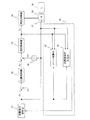
図1は本発明の実施例を示すブロック図である。位置指令演算器31で生成した位置指令値Pcと、位置検出器37で検出したモータ35または負荷36の位置検出値Pdの偏差を位置制御器32に入力すると、位置制御器32は、速度指令値Vcを出力する。一方、微分器38は位置検出値Pdを微分して速度検出値Vdを出力する。速度指令値Vcと速度検出値Vdとの偏差を速度制御器33に入力すると、速度制御器33は、トルク指令値Tcを出力する。電流制御器34は、トルク指令値Tcに従い、負荷36が取り付けられたモータ35を駆動する。
FIG. 1 is a block diagram showing an embodiment of the present invention. When the position command value Pc generated by the
図1では、上記位置制御装置に、可動部のイナーシャを算出する際の加減速条件を決定する加減速条件決定部39と、可動部のイナーシャを算出するイナーシャ演算部40とから構成されるイナーシャ推定器41が付加され、可動部のイナーシャを推定できるようになっている。
In FIG. 1, the position control device includes an inertia configured by an acceleration / deceleration
図6は、本発明の処理手順を示すフローチャートである。加減速条件決定部39で可動部のイナーシャを算出する際の加減速条件を決定後、イナーシャ演算部40で可動部のイナーシャを算出する。なお、加減速条件決定部39、及び、イナーシャ演算部40、それぞれの処理手順については、図7〜図12のフローチャートを用いて各実施例の項目で説明する。
FIG. 6 is a flowchart showing the processing procedure of the present invention. After the acceleration / deceleration
[実施例1]
まず、図2を用いて加減速条件決定部39の動作を説明する。図16のように、モータ位置によって重力の影響が異なる機械構成の場合、重力分をキャンセルするために要するトルク(重力トルク)Tgは回転角θに応じて図2の最上段のように変化する。
[Example 1]
First, the operation of the acceleration / deceleration
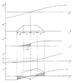
この時、加減速条件決定部39は、図2の2段目のような加速度指令値Acを定める。即ち、Tgがゼロとなる位置を中心にモータ35や負荷36などの被駆動体の加速度が線対称に変化するような加速指令を構成する。例えば図2のようにt2の間、加速度をゼロから上昇させ、t1の間一定加速度で被駆動体を駆動し、Tgがゼロとなる位置に到達する。その後も、t1の間一定加速度で駆動を続け、t2の間、加速度をゼロまで減少させて加速を終了する。このとき、Tgがゼロとなる位置は機械構成等に基づき、予め定めることができるものとする。
At this time, the acceleration / deceleration
上記のようにして定めた加速度指令値Acを積分することにより、図2の3段目に示したような速度指令値Vcを得ることができる。更に、速度指令値Vcを積分することにより、図2の4段目に示したような位置指令値Pcを得ることができる。 By integrating the acceleration command value Ac determined as described above, a speed command value Vc as shown in the third stage of FIG. 2 can be obtained. Further, by integrating the speed command value Vc, a position command value Pc as shown in the fourth stage of FIG. 2 can be obtained.
ここで、位置指令値Pcは、Tgがゼロとなる位置を原点0とすると、原点0からθsだけ前進した位置が加速開始点となるように構成される。ここで、θsの大きさは、加速開始時点からTgがゼロとなる位置を通過するまでの間の速度指令値Vcを積分することによって求めることができる。
Here, the position command value Pc is configured such that a position advanced by θs from the
加減速条件決定部39は上記のような位置指令値Pcが位置指令演算器31から出力されるよう、加速開始点−θsや加減速時間t1,t2などの加減速条件を位置指令演算器31に通知する。
The acceleration / deceleration
位置指令演算器31から図2の4段目に示したような位置指令値Pcが出力されると、位置制御器32、速度制御器33、電流制御器34を経てモータ35が駆動される。
When the position command value Pc as shown in the fourth stage of FIG. 2 is output from the
このとき、速度制御器33から出力されるトルク指令値Tcは図2の最下段のように変化する。重力の影響を受けない状況下では、図2の最下段の一点鎖線で示したように、加速度指令値Acに比例したトルク指令値Tcとなるが、重力の影響を受けた状況下では、トルク指令値に、被駆動体を加速するために必要な加速トルクのほか、重力分をキャンセルするために要するトルクが含まれるため、図2の最下段の実線で示したような特性となる。
At this time, the torque command value Tc output from the
この時、図2の最下段の斜線で示したトルクが重力分をキャンセルするために要するトルクTgに相当し、原点0を通過するタイミングでTgに相当するトルクがゼロとなる。
At this time, the torque indicated by the hatched line at the bottom in FIG. 2 corresponds to the torque Tg required to cancel the gravitational component, and the torque corresponding to Tg becomes zero when passing through the
次に、イナーシャ演算部40の動作を説明する。イナーシャ演算部40は、位置指令値Pcから加減速状態を判別し、加減速状態にあるときのトルク指令値Tc、及び位置検出値Pdを二階微分して得られる加速度検出値Adを積算する。なお、加速度検出値Adは、モータや被駆動部に加速度センサを設けて取得するようにしてもよい。加減速終了後、トルク指令値Tcの積算値を加速度検出値Adの積算値で除することによって、可動部のイナーシャを算出することができる。
Next, the operation of the
このとき積算されるトルク指令値Tcには重力分をキャンセルするために要するトルクTgが含まれるが、図2の最下段の斜線で示したように、原点0を通過する前後でTgの符号は反転する。そのため、加速時のトルク指令値Tcを積算すると、原点0を通過する前後で重力分をキャンセルするために要するトルクTgが相殺され、トルク指令値Tcの積算値は被駆動体を加速するために必要な加速トルクの積算値とほぼ等しくなる。結果、加速するために必要な加速トルクの積算値が加速度検出値Adの積算値で除され、重力の影響を排除した状態での可動部のイナーシャの算出が可能となる。
The torque command value Tc accumulated at this time includes the torque Tg required for canceling the gravity component, but the sign of Tg before and after passing through the
なお、上記実施例では、図2を例に加速動作にて説明を行ったが、イナーシャの算出は上記動作に限定されるものではない。図2では位置−θsからθeまで加速する動作を示しているが、例えば、位置θsから−θeまで加速するなど動作方向を逆にすることも可能であるほか、位置θeから−θsまで減速する、あるいは、位置−θeからθsまで減速するなど加速動作を減速動作に変更してイナーシャを算出することも可能である。 In the above embodiment, the acceleration operation has been described with reference to FIG. 2 as an example. However, the calculation of inertia is not limited to the above operation. Although FIG. 2 shows an operation of accelerating from the position -θs to θe, for example, it is possible to reverse the operation direction such as accelerating from the position θs to -θe, and to decelerate from the position θe to -θs. Alternatively, the inertia can be calculated by changing the acceleration operation to a deceleration operation, such as decelerating from position -θe to θs.
ここで、図6の加減速条件決定部39、イナーシャ演算部40の処理手順を纏めると図7のフローチャートとなる。
Here, the processing procedure of the acceleration / deceleration
まず、加減速条件決定部39は[Step A1]で、Tgがゼロとなる位置を中心に加減速する加速度指令値Acを定める。次に、[Step A2]で、加速度指令値Acを積分して速度指令値Vcを定める。更に、[Step A3]で、速度指令値Vcを積分して位置指令値Pcを定め、位置指令演算器31で使用する加減速条件を決定する。すると、[Step A3]で決定した加減速条件に従い、モータ35が駆動される。
First, the acceleration / deceleration
一方、イナーシャ演算部40は[Step B1]で、位置指令値Pcから加減速状態を検出し、[Step B2]で、加減速時のトルク指令値Tc、及び加速度検出値Adを積算する。加減速終了後、[Step B3]で、トルク指令値Tcの積算値を加速度検出値Adの積算値で除することによって、可動部のイナーシャJを算出する。
On the other hand, the
以上のように、本発明によるイナーシャ推定方法によれば、イナーシャ推定用にトルク指令値を積算する過程で、重力トルクの影響を相殺するよう、被駆動体を加減速駆動するため、モータ位置によって重力の影響が異なる機械構成であっても、正確にイナーシャを推定することができる。 As described above, according to the inertia estimation method of the present invention, in the process of accumulating the torque command value for inertia estimation, the driven body is accelerated / decelerated so as to cancel the influence of the gravitational torque. Inertia can be accurately estimated even in a machine configuration in which the influence of gravity is different.
[実施例2]
次に、上記実施例1を改良した実施形態について説明する。ここで説明する実施形態は、上記実施例1に対し、加減速条件決定部39の機能を拡張するものである。
[Example 2]
Next, an embodiment in which the first embodiment is improved will be described. In the embodiment described here, the function of the acceleration / deceleration
実施例1において、重力分をキャンセルするために要するトルクTgがゼロとなる位置は機械構成等に基づき、予め定めることができるものとした。しかし、図3のようにテーブル23上にワーク24をアンバランスに設置した場合など、重心位置がずれた状態では、重力分をキャンセルするために要するトルクTgがゼロとなる位置もずれた状態となってしまう。
In the first embodiment, the position where the torque Tg required to cancel the gravitational component becomes zero can be determined in advance based on the machine configuration or the like. However, when the position of the center of gravity is deviated, such as when the
例えば、ワーク24が設置されていない時の重力分をキャンセルするために要するトルクTgの特性が、図3の下段の点線で示した特性であったとする。一方、ワーク24を設置した場合にバランスが保たれる機械姿勢がモータ21の回転角でθrだけずれた位置であったとする。この場合、Tgの特性は図3の下段の実線で示した特性となり、ワーク24を設置していない状態に対し、θrだけずれた位置で、Tgの大きさはゼロとなる。
For example, it is assumed that the characteristic of the torque Tg required for canceling the gravitational component when the
上記ずれを含んだ状態では、実施例1のように、イナーシャ推定用にトルク指令値を積算する過程で、重力トルクの影響を相殺することができない。即ち、正確にイナーシャを推定するためには、上記ずれを補正する必要がある。そこで、本実施形態では、上記実施例1の加減速条件決定部39に対し、以下の機能を付加する。
In the state including the deviation, the influence of gravity torque cannot be offset in the process of integrating torque command values for inertia estimation as in the first embodiment. That is, in order to accurately estimate the inertia, it is necessary to correct the deviation. Therefore, in the present embodiment, the following function is added to the acceleration / deceleration
モータ21の回転角θに対する重力分をキャンセルするために要するトルクTgの大きさは、モータを一定速駆動したときのトルク指令値Tcとほぼ等しく、回転角θに対するTcを測定することによって定めることが可能である。そこで、加減速条件決定部39において、モータを一定速駆動したときのTcを監視し、Tcがゼロとなるときの位置検出値PdからTgがゼロとなる位置を特定する。
The magnitude of the torque Tg required to cancel the gravity component with respect to the rotation angle θ of the
その上で、実施例1と同様に、位置指令値Pcを構成し、イナーシャ演算部40でイナーシャを算出する。これにより、重力の影響を排除した状態での可動部のイナーシャの算出が可能となる。
After that, as in the first embodiment, the position command value Pc is configured, and the
ここで、図6の加減速条件決定部39の処理手順を纏めると図8のフローチャートとなる。
Here, the processing procedure of the acceleration / deceleration
まず、[Step C1]で、モータが一定速駆動されていることを検出し、[Step C2]で、一定速時のトルク指令値Tcを測定・監視する。更に、[Step C3]で、トルク指令値Tcの極性が反転する(Tcがゼロとなる)ときの位置検出値PdからTgがゼロとなる位置を特定する。その後、[Step A1]から[Step A3]を行うことにより、位置指令演算器31で使用する加減速条件を決定する。
First, in [Step C1], it is detected that the motor is driven at a constant speed, and in [Step C2], a torque command value Tc at a constant speed is measured and monitored. Furthermore, in [Step C3], the position where Tg becomes zero is specified from the position detection value Pd when the polarity of the torque command value Tc is reversed (Tc becomes zero). Then, the acceleration / deceleration conditions used by the
以上のように、本発明によるイナーシャ推定方法によれば、被駆動体の重心位置がずれた状態でも、重力トルクの影響がゼロとなる位置を測定により特定し、トルク指令値を積算する過程で、重力トルクの影響を相殺するよう、被駆動体を加減速駆動するため、モータ位置によって重力の影響が異なる機械構成であっても、正確にイナーシャを推定することができる。 As described above, according to the inertia estimation method according to the present invention, even when the position of the center of gravity of the driven body is deviated, the position where the influence of gravity torque is zero is specified by measurement, and the torque command value is integrated. In addition, since the driven body is driven to accelerate and decelerate so as to cancel the influence of the gravitational torque, the inertia can be accurately estimated even in a mechanical configuration in which the influence of the gravitational force differs depending on the motor position.
[実施例3]
次に、上記実施例1を改良した実施形態について説明する。ここで説明する実施形態は、上記実施例1に対し、加減速条件決定部39の機能を拡張するものである。
[Example 3]
Next, an embodiment in which the first embodiment is improved will be described. In the embodiment described here, the function of the acceleration / deceleration
実施例1では、図2において、重力分をキャンセルするために要するトルクTgがゼロとなる位置を中心にモータ35や負荷36などの被駆動体を加速する指令を構成し、位置−θsからθeまでの間、加速させることを示した。しかし、加速中の速度は徐々に高くなるため、同一時間あたりの移動量は、時間経過とともに大きくなる。
In the first embodiment, in FIG. 2, a command for accelerating a driven body such as the
即ち、図4に示すように、加速開始位置−θsと加速終了位置θeの大小関係はθs<θeとなり、重力分をキャンセルするために要するトルクTgの大きさも|Tg(−θs)|<|Tg(θe)|となる。結果、重力の影響はTgがゼロとなる前後で完全に相殺することはできず、推定されたイナーシャには僅かながら重力トルクの影響が残ることとなる。そこで、本実施形態では、上記実施例1の加減速条件決定部39に対し、以下の機能を付加する。
That is, as shown in FIG. 4, the magnitude relationship between the acceleration start position −θs and the acceleration end position θe is θs <θe, and the magnitude of the torque Tg required to cancel the gravitational component is also | Tg (−θs) | <| Tg (θe) | As a result, the influence of gravity cannot be completely canceled before and after Tg becomes zero, and a slight influence of gravity torque remains on the estimated inertia. Therefore, in the present embodiment, the following function is added to the acceleration / deceleration
実施例1と同様に、位置指令値Pcを構成後、モータ21の回転角θに対する重力分をキャンセルするために要するトルクTgの特性をベースにして、図4の4段目のように、経過時間tに対するTgの特性を計算する。
As in the first embodiment, after the position command value Pc is configured, the elapsed time as shown in the fourth stage of FIG. 4 is based on the characteristics of the torque Tg required to cancel the gravitational component with respect to the rotation angle θ of the
次に、重力分をキャンセルするために要するトルクTgがゼロとなる位置(原点0)を通過する前後で、Tgの積算値の大きさが等しくなる時刻(加速開始時点からTgの積算を開始し、積算値が再びゼロとなる時刻)を求める。 Next, before and after passing through a position (origin 0) where the torque Tg required for canceling the gravitational component is zero, the time when the integrated value of Tg becomes equal (the integration of Tg starts from the acceleration start time). , The time when the integrated value becomes zero again).
そして、図4の最下段のように、上記時刻にて加速が終了するよう、加速時間を短縮した加速度指令値Acを定める。なお、図4ではt0分の加速時間の短縮が必要と判断し、一定加速度で加速している時間t1をt0分短縮して、t1’と改めている。この加速度指令Acは、Tgがゼロとなる位置を中心として、重力トルクTgの積算値が対称性を持つような指令と言える。 Then, as shown in the lowermost part of FIG. 4, an acceleration command value Ac with a reduced acceleration time is determined so that the acceleration ends at the above time. In FIG. 4, it is determined that it is necessary to shorten the acceleration time of t0, and the time t1 accelerating at a constant acceleration is shortened by t0 and changed to t1 '. The acceleration command Ac can be said to be a command in which the integrated value of the gravitational torque Tg has symmetry with respect to the position where Tg becomes zero.
このように、加減速時間を調整した加速度指令値Acを二階積分して、位置指令値Pcを再構成する。この再構成した位置指令値Pcに従い、加減速駆動し、実施例1と同様に、イナーシャ演算部40でイナーシャを算出する。
In this way, the acceleration command value Ac adjusted for the acceleration / deceleration time is second-order integrated to reconstruct the position command value Pc. In accordance with the reconfigured position command value Pc, acceleration / deceleration driving is performed, and the
以上の操作により、原点0を通過する前後で重力分をキャンセルするために要するトルクTgがより正確に相殺されるため、重力の影響を排除した状態での可動部のイナーシャの算出が可能となる。
By the above operation, the torque Tg required for canceling the gravitational force before and after passing through the
ここで、図6の加減速条件決定部39の処理手順を纏めると図9のフローチャートとなる。
Here, the processing procedure of the acceleration / deceleration
まず、[Step A1]から[Step A3]を行うことにより、位置指令値Pcを定める。次に、[Step D1]で、時間tに対するTgの特性を計算する。更に、[Step D2]で、Tgがゼロとなる位置を通過する前後で、Tgの積算値の大きさが等しくなる時刻を求める。この時刻に位置指令値Pcによる加減速が完了するよう、[Step D3]で、位置指令演算器31で使用する加減速条件を再決定する。
First, the position command value Pc is determined by performing [Step A1] to [Step A3]. Next, in [Step D1], the characteristic of Tg with respect to time t is calculated. Further, at [Step D2], the time at which the magnitudes of the integrated values of Tg are equal before and after passing through the position where Tg becomes zero is obtained. The acceleration / deceleration conditions used in the
以上のように、本発明によるイナーシャ推定方法によれば、重力トルクの影響がより正確に相殺されるよう、加減速時間を調整したため、モータ位置によって重力の影響が異なる機械構成であっても、より正確にイナーシャを推定することができる。 As described above, according to the inertia estimation method according to the present invention, the acceleration / deceleration time is adjusted so that the influence of the gravity torque is more accurately offset. Inertia can be estimated more accurately.
[実施例4]
次に、上記実施例2を改良した実施形態について説明する。ここで説明する実施形態は、上記実施例2に対し、加減速条件決定部39の機能を拡張するものである。
[Example 4]
Next, an embodiment in which the above Example 2 is improved will be described. In the embodiment described here, the function of the acceleration / deceleration
重力分をキャンセルするために要するトルクTgの大きさを、一定速駆動時のトルク指令値Tcを測定して定めた場合、Tcに摩擦トルクの影響が含まれると、図5の最上段のような波形となる。即ち、実線で示したTgの真値に対し、モータ21を正方向に回転させた場合は点線で示したような測定結果が得られ、負方向に回転させた場合は一点鎖線で示したような測定結果が得られる。
When the magnitude of the torque Tg required to cancel the gravitational component is determined by measuring the torque command value Tc during constant speed driving, if the influence of friction torque is included in Tc, Waveform. That is, when the
即ち、重力分をキャンセルするために要するトルクTgがゼロとなる位置が真値からずれてしまう。これは、移動方向によって作用する方向が異なる摩擦トルクの影響が含まれているためである。 That is, the position where the torque Tg required for canceling the gravitational component is zero shifts from the true value. This is because the influence of the friction torque in which the acting direction differs depending on the moving direction is included.
上記ずれを含んだ状態では、実施例2のように、イナーシャ推定用にトルク指令値を積算する過程で、重力トルクの影響を相殺することができない。即ち、正確にイナーシャを推定するためには、上記ずれを補正する必要がある。そこで、本実施形態では、上記実施例2の加減速条件決定部39に対し、以下の機能を付加する。
In the state including the deviation, the influence of gravity torque cannot be offset in the process of integrating the torque command value for inertia estimation as in the second embodiment. That is, in order to accurately estimate the inertia, it is necessary to correct the deviation. Therefore, in the present embodiment, the following functions are added to the acceleration / deceleration
モータ21の回転角θに対する重力分をキャンセルするために要するトルクTgの大きさを測定するにあたり、モータを正方向に一定速駆動した場合と、負方向に一定速駆動した場合、それぞれで回転角θに対するトルク指令値Tcを測定する。その上で、それぞれの場合においてTcがゼロとなるときの位置検出値Pdを特定し、その中間点をTgがゼロとなる位置とする。
In measuring the magnitude of the torque Tg required to cancel the gravitational force with respect to the rotation angle θ of the
その上で、実施例2と同様に、位置指令値Pcを構成し、イナーシャ演算部40でイナーシャを算出する。これにより、重力の影響を排除した状態での可動部のイナーシャの算出が可能となる。
After that, as in the second embodiment, the position command value Pc is configured, and the
ここで、図6の加減速条件決定部39の処理手順を纏めると図10のフローチャートとなる。
Here, the processing procedure of the acceleration / deceleration
まず、[Step E1]で、モータが正方向に一定速駆動されていることを検出し、[Step E2]で、正方向移動一定速時のトルク指令値Tcを測定・監視する。更に、[Step E3]で、トルク指令値Tcの極性が反転する(Tcがゼロとなる)ときのPdを特定する。 First, at [Step E1], it is detected that the motor is being driven at a constant speed in the positive direction, and at [Step E2], the torque command value Tc at the constant speed in the forward direction is measured and monitored. Furthermore, [Step E3] specifies Pd when the polarity of the torque command value Tc is reversed (Tc becomes zero).
一方、[Step E4]で、モータが負方向に一定速駆動されていることを検出し、[Step E5]で、負方向移動一定速時のトルク指令値Tcを測定・監視する。更に、[Step E6]で、トルク指令値Tcの極性が反転する(Tcがゼロとなる)ときの位置検出値Pdを特定する。 On the other hand, in [Step E4], it is detected that the motor is being driven at a constant speed in the negative direction, and in [Step E5], the torque command value Tc at the time of constant movement in the negative direction is measured and monitored. Further, in [Step E6], the position detection value Pd when the polarity of the torque command value Tc is reversed (Tc becomes zero) is specified.
その後、[Step E7]で、[Step E3]で特定した位置(Pd)と[Step E6]で特定した位置(Pd)の中間点をTgがゼロとなる位置と定め、その上で[Step A1]から[Step A3]を行うことにより、位置指令演算器31で使用する加減速条件を決定する。
Then, in [Step E7], an intermediate point between the position (Pd) specified in [Step E3] and the position (Pd) specified in [Step E6] is determined as a position where Tg becomes zero, and then [Step A1 ] To [Step A3], the acceleration / deceleration conditions used in the
なお、[Step E1]から[Step E3]と[Step E4]から[Step E6]については、その順序を入れ替えることは可能である。即ち、[Step E4]から[Step E6]を実施後、[Step E1]から[Step E3]を行っても支障ない。 Note that the order of [Step E1] to [Step E3] and [Step E4] to [Step E6] can be interchanged. That is, there is no problem even if [Step E1] to [Step E3] are performed after performing [Step E4] to [Step E6].
以上のように、本発明によるイナーシャ推定方法によれば、摩擦トルクの影響が大きい場合でも、重力トルクの影響がゼロとなる位置を特定した上で、トルク指令値を積算する過程で、重力トルクの影響を相殺するよう、被駆動体を加減速駆動するため、モータ位置によって重力の影響が異なる機械構成であっても、正確にイナーシャを推定することができる。 As described above, according to the inertia estimation method of the present invention, even when the influence of the friction torque is large, the position where the influence of the gravity torque becomes zero is specified, and the process of integrating the torque command value Since the driven body is driven to accelerate and decelerate so as to offset the influence of the inertia, the inertia can be accurately estimated even in a mechanical configuration in which the influence of gravity differs depending on the motor position.
[実施例5]
次に、上記実施例4を改良した実施形態について説明する。ここで説明する実施形態は、上記実施例4に対し、イナーシャ演算部40の機能を拡張するものである。
[Example 5]
Next, an embodiment in which the above Example 4 is improved will be described. In the embodiment described here, the function of the
トルク指令値Tcに含まれる摩擦トルクの影響が大きく、加減速時に必要となる加速トルクに対し、無視できない大きさの場合、Tcを積算してイナーシャを算出すると、摩擦トルクの影響でイナーシャ推定値に誤差が発生してしまう。そこで、本実施形態では、上記実施例4のイナーシャ演算部40に対し、以下の機能を付加する。
If the influence of the friction torque included in the torque command value Tc is large and the acceleration torque required at the time of acceleration / deceleration is a magnitude that cannot be ignored, calculating the inertia by integrating the Tc results in the estimated inertia value due to the influence of the friction torque. An error will occur. Therefore, in the present embodiment, the following functions are added to the
摩擦トルクの影響が無視できない状況下でのトルク指令値Tcには、図5の最下段に示したように、加減速トルクTa、重力分をキャンセルするために要するトルクTg、摩擦分をキャンセルするために要するトルクTfが含まれる。図5の最下段において、一点鎖線はTaとTgを考慮した時のTc、実線はTaとTgに加えてTfを考慮した時のTcをそれぞれ示している。一点鎖線で示した特性に対し、実線で示した特性は、軸駆動のために斜線で示したTf分のトルクが必要になる。ここで、各トルクの関係をモータ21の回転角θを用いて纏めると、下記式4のように表現できる。
In the torque command value Tc under the condition where the influence of the friction torque cannot be ignored, the acceleration / deceleration torque Ta and the torque Tg and the friction component required for canceling the gravity component are canceled as shown in the lowermost stage of FIG. The torque Tf required for this is included. In the lowermost stage of FIG. 5, the alternate long and short dash line indicates Tc when Ta and Tg are considered, and the solid line indicates Tc when Tf is considered in addition to Ta and Tg. In contrast to the characteristics indicated by the alternate long and short dash line, the characteristics indicated by the solid line require a torque corresponding to Tf indicated by the oblique lines in order to drive the shaft. Here, when the relationship of each torque is summarized using the rotation angle θ of the
Tc= Ta+Tg(θ)+Tf [加速時(正方向移動時)]
−Ta+Tg(θ)+Tf [減速時(正方向移動時)]
−Ta+Tg(θ)−Tf [加速時(負方向移動時)]
Ta+Tg(θ)−Tf [減速時(負方向移動時)] ・・・式4
Tc = Ta + Tg (θ) + Tf [acceleration (moving in the positive direction)]
-Ta + Tg (θ) + Tf [Deceleration (moving in the positive direction)]
−Ta + Tg (θ) −Tf [acceleration (moving in negative direction)]
Ta + Tg (θ) −Tf [Deceleration (moving in negative direction)]
加減速トルクTaは、加速時と減速時とで加速度の符号が反転するため、異符号となる。また、正方向移動時と負方向移動時とで加速方向が相反するため、異符号となる。一方、重力分をキャンセルするために要するトルクTgは位置によって決定されるため、同位置であれば加減速や移動方向に左右されず、同一符号となる。また、摩擦分をキャンセルするために要するトルクTfは軸移動に対し逆らうように作用するため、移動方向によって符号が決定される。 The acceleration / deceleration torque Ta has a different sign because the sign of acceleration is inverted between acceleration and deceleration. Further, since the acceleration directions are contradictory when moving in the positive direction and when moving in the negative direction, they have different signs. On the other hand, since the torque Tg required for canceling the gravitational component is determined by the position, the same sign is used regardless of acceleration / deceleration or movement direction at the same position. Further, since the torque Tf required to cancel the frictional component acts against the axial movement, the sign is determined by the moving direction.
ここで、摩擦トルクの影響は、同一位置にて加速動作、減速動作を行うことによって、相殺することができる。例えば、加速時(正方向移動時)と減速時(正方向移動時)とで差分をとることによって、トルク指令値Tc、またはトルク指令値Tcの積算値に含まれる、摩擦分をキャンセルするために要するトルクTfを相殺することができる。 Here, the influence of the friction torque can be offset by performing the acceleration operation and the deceleration operation at the same position. For example, by calculating the difference between acceleration (moving in the positive direction) and deceleration (moving in the positive direction), the frictional amount included in the torque command value Tc or the integrated value of the torque command value Tc is canceled. The torque Tf required for this can be canceled out.
同様に、加速時(正方向移動時)と減速時(負方向移動時)とで加算、加速時(負方向移動時)と減速時(負方向移動時)とで減算、加速時(負方向移動時)と減速時(正方向移動時)とで加算しても、摩擦分をキャンセルするために要するトルクTfを相殺することができる。 Similarly, the value is added when accelerating (moving in the positive direction) and decelerating (moving in the negative direction), subtracted when accelerating (moving in the negative direction) and decelerating (moving in the negative direction), and accelerated (negative direction) The torque Tf required for canceling the friction can be canceled out even when adding during the movement) and during the deceleration (moving in the positive direction).
ただし、加速時(正方向移動時)と減速時(正方向移動時)、加速時(負方向移動時)と減速時(負方向移動時)の組合せの場合、加減速する区間を同一としても、同じ地点を通過するときの速度が異なるため、同一時間あたりの移動量に違いが出る。結果、重力分をキャンセルするために要するトルクTgがゼロとなる位置や、Tgの変化の仕方が変わるため、Tgを積算した場合に、加速時と減速時とで値に違いが出てしまう。このため、イナーシャを算出する際に重力トルクの影響が僅かながら残ってしまう。よって、好適な形態として、加速時(正方向移動時)と減速時(負方向移動時)、加速時(負方向移動時)と減速時(正方向移動時)の組合せにて、摩擦分をキャンセルするために要するトルクTfを相殺することを推奨する。 However, when accelerating (moving in the positive direction), decelerating (moving in the positive direction), accelerating (moving in the negative direction), and decelerating (moving in the negative direction), the acceleration / deceleration interval may be the same. Because the speed when passing through the same point is different, the amount of movement per same time is different. As a result, the position at which the torque Tg required for canceling the gravitational component becomes zero and the manner in which the Tg changes change, so that when Tg is integrated, there is a difference in value between acceleration and deceleration. For this reason, the influence of gravity torque remains slightly when calculating the inertia. Therefore, as a preferred form, the friction amount is reduced by a combination of acceleration (moving in the positive direction) and deceleration (moving in the negative direction), acceleration (moving in the negative direction), and deceleration (moving in the positive direction). It is recommended to cancel the torque Tf required for canceling.
上記のように、摩擦分をキャンセルするために要するトルクTfを相殺するため、位置制御装置は、加減速条件決定部39が定めた重力分をキャンセルするために要するトルクTgがゼロとなる位置を中心とした、加速動作、減速動作を行い、イナーシャ演算部40は、加速動作、減速動作、それぞれの動作に対し、トルク指令値Tc、加速度検出値Adを積算する。
As described above, in order to cancel the torque Tf required for canceling the friction component, the position control device determines the position where the torque Tg required for canceling the gravity component determined by the acceleration / deceleration
加減速動作終了後、加速動作、減速動作それぞれにおいて、トルク指令値Tcの積算値を加速度検出値Adの積算値で除し、両者の平均値から可動部のイナーシャを算出する。この場合、加速動作から算出される可動部のイナーシャは摩擦トルクの影響分だけイナーシャが大きく算出され、減速動作から算出される可動部のイナーシャは摩擦トルクの影響分だけイナーシャが小さく算出されるが、両者の平均値をとることによって、摩擦トルクの影響分が相殺された可動部のイナーシャを算出することができる。 After the acceleration / deceleration operation is completed, in each of the acceleration operation and the deceleration operation, the integrated value of the torque command value Tc is divided by the integrated value of the acceleration detection value Ad, and the inertia of the movable part is calculated from the average value of both. In this case, the inertia of the movable part calculated from the acceleration operation is calculated to be large by the influence of the friction torque, and the inertia of the movable part calculated from the deceleration operation is calculated to be small by the influence of the friction torque. By taking the average value of the two, the inertia of the movable part in which the influence of the friction torque is canceled can be calculated.
あるいは、加速動作、減速動作それぞれのトルク指令値Tcの積算値、加速度検出値Adの積算値を合算して、トルク指令積算合算値、加速度検出積算合算値を算出し、その上で、トルク指令積算合算値を加速度検出積算合算値で除することによって可動部のイナーシャを算出する。この場合、トルク指令積算合算値を算出する過程で、加速動作時のトルク指令値Tcの積算値に含まれる摩擦トルク分と減速動作時のトルク指令値Tcの積算値に含まれる摩擦トルク分とを相殺することができる。 Alternatively, the integrated value of the torque command value Tc and the integrated value of the acceleration detection value Ad for each of the acceleration operation and the deceleration operation are added to calculate the torque command integrated sum value and the acceleration detection integrated sum value, and then the torque command The inertia of the movable part is calculated by dividing the integrated total value by the acceleration detection integrated total value. In this case, in the process of calculating the torque command integrated total value, the friction torque component included in the integrated value of the torque command value Tc during acceleration operation and the friction torque component included in the integrated value of the torque command value Tc during deceleration operation Can be offset.
ここで、図6のイナーシャ演算部40の処理手順を纏めると図11、あるいは図12のフローチャートとなる。
Here, the processing procedure of the
図11では、まず、[Step F1]で、位置指令値Pcから加速状態を検出し、[Step F2]で、加速時のトルク指令値Tc、及び加速度検出値Adを積算する。加速終了後、[Step F3]で、トルク指令値Tcの積算値を加速度検出値Adの積算値で除することによって、加速イナーシャJaを算出する。 In FIG. 11, first, in [Step F1], an acceleration state is detected from the position command value Pc, and in [Step F2], the torque command value Tc during acceleration and the acceleration detection value Ad are integrated. After the completion of acceleration, in [Step F3], the acceleration inertia Ja is calculated by dividing the integrated value of the torque command value Tc by the integrated value of the acceleration detection value Ad.
また、[Step F4]で、位置指令値Pcから減速状態を検出し、[Step F5]で、減速時のトルク指令値Tc、及び加速度検出値Adを積算する。減速終了後、[Step F6]で、トルク指令値Tcの積算値を加速度検出値Adの積算値で除することによって、減速イナーシャJdを算出する。 Further, in [Step F4], the deceleration state is detected from the position command value Pc, and in [Step F5], the torque command value Tc during deceleration and the acceleration detection value Ad are integrated. After the deceleration is completed, in [Step F6], the deceleration inertia Jd is calculated by dividing the integrated value of the torque command value Tc by the integrated value of the acceleration detection value Ad.
その後、[Step F7]で、加速イナーシャJaと減速イナーシャJdの平均をとり、可動部のイナーシャJを算出する。 After that, in [Step F7], the average of the acceleration inertia Ja and the deceleration inertia Jd is calculated, and the inertia J of the movable part is calculated.
一方、図12では、まず、[Step G1]で、位置指令値Pcから加速状態を検出し、[Step G2]で、加速時のトルク指令値Tc、及び加速度検出値Adを積算する。その後、[Step G3]で、位置指令値Pcから減速状態を検出し、[Step G4]で、減速時のトルク指令値Tc、及び加速度検出値Adを積算する。 On the other hand, in FIG. 12, first, in [Step G1], the acceleration state is detected from the position command value Pc, and in [Step G2], the torque command value Tc during acceleration and the acceleration detection value Ad are integrated. Thereafter, in [Step G3], the deceleration state is detected from the position command value Pc, and in [Step G4], the torque command value Tc during deceleration and the acceleration detection value Ad are integrated.
次に、[Step G5]で、加速時のトルク指令値Tcの積算値と減速時のトルクし指令値Tcの積算値を合算してトルク指令積算合算値を算出し、[Step G6]で、加速時の加速度検出値Adの積算値と減速時の加速度検出値Adの積算値を合算して加速度検出積算合算値を算出する。その上で、[Step G7]で、トルク指令積算合算値を加速度検出積算合算値で除することによって、可動部のイナーシャJを算出する。 Next, in [Step G5], an integrated value of the torque command value Tc at the time of acceleration and an integrated value of the torque command value Tc at the time of deceleration are added to calculate a torque command integrated total value, and in [Step G6], The integrated value of the acceleration detection value Ad at the time of acceleration and the integrated value of the acceleration detection value Ad at the time of deceleration are added together to calculate an acceleration detection integrated value. Then, in [Step G7], the inertia J of the movable part is calculated by dividing the torque command integrated total value by the acceleration detection integrated total value.
以上のように、本発明によるイナーシャ推定方法によれば、イナーシャ推定用にトルク指令値を積算する過程で、重力トルクの影響を相殺するとともに、加速動作と減速動作とを組み合わせることにより、摩擦トルクの影響を相殺するため、モータ位置によって重力の影響が異なる、かつ摩擦トルクの影響が無視できない機械構成であっても、正確にイナーシャを推定することができる。 As described above, according to the inertia estimation method according to the present invention, in the process of accumulating the torque command value for the inertia estimation, the influence of the gravitational torque is canceled, and the friction torque is obtained by combining the acceleration operation and the deceleration operation. Therefore, the inertia can be accurately estimated even in a machine configuration in which the influence of gravity differs depending on the motor position and the influence of friction torque cannot be ignored.
なお、上記実施例1〜5では、トルク指令値Tcを積算した値を用いてイナーシャを算出することを示したが、本発明はこれに限定されるものではない。例えば、電流制御器34内でトルク指令値Tcから変換される電流指令値や、モータ35に通電された電流を検出した電流検出値等を積算し、トルク定数等を乗じてトルク指令値Tcの積算値に相当する値に変換して、イナーシャを算出することも可能である。
In the first to fifth embodiments, the inertia is calculated using a value obtained by integrating the torque command value Tc. However, the present invention is not limited to this. For example, the current command value converted from the torque command value Tc in the
11,14,33 速度制御器、12,21,35 モータ、13,16 積分器、15 モータモデル、22 アーム、23 テーブル、24 ワーク、31 位置指令演算器、32 位置制御器、34 電流制御器、36 負荷、37 位置検出器、38 微分器、39 加減速条件決定部、40 イナーシャ演算部、41 イナーシャ推定器。 11, 14, 33 Speed controller, 12, 21, 35 Motor, 13, 16 Integrator, 15 Motor model, 22 Arm, 23 Table, 24 Workpiece, 31 Position command calculator, 32 Position controller, 34 Current controller , 36 load, 37 position detector, 38 differentiator, 39 acceleration / deceleration condition determining unit, 40 inertia calculating unit, 41 inertia estimator.
Claims (7)
前記可動部を駆動させた際に、重力の影響をキャンセルするためのトルクである重力トルクがゼロになる位置を中心として、前記重力トルクの積算値または前記可動部の加速度が対称性を持つような加速駆動条件または減速駆動条件の少なくとも一方を決定する加減速条件決定工程と、
決定された加速または減速駆動条件に従ってモータを駆動した際に得られるトルク指令値の積算値と、前記モータまたは被駆動部の加速度検出値の積算値と、の比から前記可動部のイナーシャを算出するイナーシャ演算工程と、
を備えることを特徴とするイナーシャ推定方法。 A torque command value is calculated based on a position command value and a position detection value of a motor or a driven part coupled to the motor, and the motor and the driven are mounted on a device that drives the motor according to the torque command value An inertia estimation method for estimating inertia of a movable part including a part,
When the movable part is driven, the integrated value of the gravitational torque or the acceleration of the movable part is symmetrical with respect to a position where the gravitational torque, which is a torque for canceling the influence of gravity, becomes zero. An acceleration / deceleration condition determining step for determining at least one of a proper acceleration drive condition or a deceleration drive condition;
The inertia of the movable part is calculated from the ratio of the integrated value of the torque command value obtained when the motor is driven according to the determined acceleration or deceleration drive condition and the integrated value of the acceleration detection value of the motor or driven part. An inertia calculation process,
An inertia estimation method comprising:
前記重力トルクがゼロとなる位置は、前記被駆動体を一定速駆動したときに得られる前記トルク指令値の極性が反転するタイミングにおける前記位置検出値から特定される、ことを特徴とするイナーシャ推定方法。 The inertia estimation method according to claim 1,
The position where the gravitational torque becomes zero is specified from the position detection value at the timing when the polarity of the torque command value obtained when the driven body is driven at a constant speed, and the inertia estimation is characterized in that Method.
加速駆動条件または減速駆動条件は、前記被駆動体を加速駆動または減速駆動したときに、前記重力トルクがゼロになる位置を通過する前後で、前記重力トルクの積算値の大きさが等しくなるように、加速または減速の時間が調整されている、ことを特徴とするイナーシャ推定方法。 The inertia estimation method according to claim 1, wherein:
The acceleration driving condition or the deceleration driving condition is such that when the driven body is driven to accelerate or decelerate, the magnitude of the gravitational torque integrated value becomes equal before and after passing through a position where the gravitational torque becomes zero. And an acceleration or deceleration time is adjusted.
加減速条件決定工程は、前記被駆動体を一定速で往復駆動したときのトルク指令値を監視する工程を含み、
前記重力トルクがゼロとなる位置は、往路において前記トルク指令値の極性が反転するタイミングにおける前記位置検出値と、復路において前記トルク指令値の極性が反転するタイミングにおける前記位置検出値と、の中間点から特定される、
ことを特徴とするイナーシャ推定方法。 The inertia estimation method according to any one of claims 1 to 3,
The acceleration / deceleration condition determining step includes a step of monitoring a torque command value when the driven body is reciprocally driven at a constant speed,
The position at which the gravitational torque becomes zero is an intermediate position between the position detection value at the timing when the polarity of the torque command value is reversed in the forward path and the position detection value at the timing at which the polarity of the torque command value is reversed on the return path. Identified from points,
An inertia estimation method characterized by that.
前記加減速条件決定工程において、前記重力トルクがゼロになる位置を中心として、前記重力トルクの積算値の大きさまたは加速度が線対称に変化するような加速駆動条件および減速駆動条件の両方を決定し、
前記イナーシャ演算工程は、決定された加速駆動条件および減速駆動条件に従ってモータを駆動した際のトルク指令値および加速度検出値を監視する工程を含み、
前記可動部のイナーシャは、加速駆動時のトルク指令値の積算値と加速駆動時の加速度検出値の積算値との比、および、減速駆動時のトルク指令値の積算値と減速駆動時の前記加速度検出値の積算値との比、の平均値から算出される、
ことを特徴とするイナーシャ推定方法。 The inertia estimation method according to any one of claims 1 to 4,
In the acceleration / deceleration condition determining step, both acceleration driving conditions and deceleration driving conditions are determined so that the magnitude or acceleration of the gravitational torque is changed symmetrically about the position where the gravitational torque becomes zero. And
The inertia calculation step includes a step of monitoring a torque command value and an acceleration detection value when the motor is driven according to the determined acceleration drive condition and deceleration drive condition,
The inertia of the movable part is the ratio of the integrated value of the torque command value during acceleration driving to the integrated value of the acceleration detection value during acceleration driving, and the integrated value of the torque command value during deceleration driving and the above-mentioned value during deceleration driving. Calculated from the average value of the ratio of the acceleration detection value to the integrated value,
An inertia estimation method characterized by that.
前記加減速条件決定工程において、前記重力トルクがゼロになる位置を中心として、加速度または前記重力トルクの積算値の大きさが線対称に変化するような加速駆動条件および減速駆動条件の両方を決定し、
前記イナーシャ演算工程は、加速駆動条件および減速駆動条件に従ってモータを駆動した際のトルク指令値および加速度検出値を監視する工程を含み、
前記可動部のイナーシャは、加速駆動時のトルク指令値の積算値と減速駆動時のトルク指令値の積算値との合算値、および、加速駆動時の加速度検出値の積算値と減速駆動時の加速度検出値の積算値との合算値、の比から算出される、
ことを特徴とするイナーシャ推定方法。 The inertia estimation method according to any one of claims 1 to 4,
In the accelerating / decelerating condition determining step, both acceleration driving conditions and deceleration driving conditions are determined such that the magnitude of the acceleration or the integrated value of the gravitational torque changes axisymmetrically around the position where the gravitational torque becomes zero. And
The inertia calculation step includes a step of monitoring a torque command value and an acceleration detection value when the motor is driven according to the acceleration drive condition and the deceleration drive condition,
The inertia of the movable part is the sum of the integrated value of the torque command value during acceleration driving and the integrated value of the torque command value during deceleration driving, and the integrated value of the acceleration detection value during acceleration driving and the deceleration driving value during deceleration driving. Calculated from the ratio of the sum of the acceleration detection value and the integrated value,
An inertia estimation method characterized by that.
前記可動部を駆動させた際に、重力の影響をキャンセルするためのトルクである重力トルクがゼロになる位置を中心として、前記重力トルクの積算値または加速度が対称性を持つような加速駆動条件または減速駆動条件の少なくとも一方を決定する加減速条件決定部と、
決定された加速または減速駆動条件に従ってモータを駆動した際に得られるトルク指令値の積算値と、前記モータまたは被駆動部の加速度検出値の積算値と、の比から前記可動部のイナーシャを算出するイナーシャ演算部と、
を備え、前記重力トルクがゼロとなる位置の前後で前記トルク指令値に含まれる重力トルクを相殺した上でイナーシャを算出することを特徴とするイナーシャ推定装置。 A torque command value is calculated based on a position command value and a position detection value of a motor or a driven part coupled to the motor, and is mounted on a device that drives the motor according to the torque command value, and the motor and the driven An inertia estimation device for estimating the inertia of a movable part including a part,
Acceleration driving conditions such that when the movable part is driven, the integrated value or acceleration of the gravity torque has symmetry with respect to a position where the gravity torque, which is a torque for canceling the influence of gravity, becomes zero. Or an acceleration / deceleration condition determining unit that determines at least one of the deceleration driving conditions;
The inertia of the movable part is calculated from the ratio of the integrated value of the torque command value obtained when the motor is driven according to the determined acceleration or deceleration drive condition and the integrated value of the acceleration detection value of the motor or driven part. Inertia calculation unit to
The inertia estimation apparatus calculates the inertia after canceling out the gravitational torque included in the torque command value before and after the position where the gravitational torque becomes zero.
Priority Applications (4)
| Application Number | Priority Date | Filing Date | Title |
|---|---|---|---|
| JP2013092615A JP6009397B2 (en) | 2013-04-25 | 2013-04-25 | Inertia estimation method and inertia estimation apparatus for position control device |
| DE102014105681.7A DE102014105681B4 (en) | 2013-04-25 | 2014-04-23 | INERTIA ASSESSMENT METHOD AND INERTIA ASSESSMENT DEVICE OF A POSITION CONTROL DEVICE |
| CN201410170409.8A CN104167973B (en) | 2013-04-25 | 2014-04-25 | Inertia evaluation method and inertia the estimation device of position control |
| US14/262,371 US9952249B2 (en) | 2013-04-25 | 2014-04-25 | Inertia estimating method and inertia estimation apparatus of position control apparatus |
Applications Claiming Priority (1)
| Application Number | Priority Date | Filing Date | Title |
|---|---|---|---|
| JP2013092615A JP6009397B2 (en) | 2013-04-25 | 2013-04-25 | Inertia estimation method and inertia estimation apparatus for position control device |
Publications (2)
| Publication Number | Publication Date |
|---|---|
| JP2014217165A JP2014217165A (en) | 2014-11-17 |
| JP6009397B2 true JP6009397B2 (en) | 2016-10-19 |
Family
ID=51685192
Family Applications (1)
| Application Number | Title | Priority Date | Filing Date |
|---|---|---|---|
| JP2013092615A Active JP6009397B2 (en) | 2013-04-25 | 2013-04-25 | Inertia estimation method and inertia estimation apparatus for position control device |
Country Status (4)
| Country | Link |
|---|---|
| US (1) | US9952249B2 (en) |
| JP (1) | JP6009397B2 (en) |
| CN (1) | CN104167973B (en) |
| DE (1) | DE102014105681B4 (en) |
Families Citing this family (11)
| Publication number | Priority date | Publication date | Assignee | Title |
|---|---|---|---|---|
| CN106301146B (en) * | 2015-06-26 | 2018-11-30 | 三垦电气株式会社 | The inertia detection device and inertia detection method of electric motor system |
| US9988751B2 (en) | 2015-07-29 | 2018-06-05 | Whirlpool Corporation | Laundry treating appliance and methods of reducing tub contact therein |
| US10273621B2 (en) | 2015-10-01 | 2019-04-30 | Whirlpool Corporation | Laundry treating appliance and methods of operation |
| US9890490B2 (en) | 2015-11-19 | 2018-02-13 | Whirlpool Corporation | Laundry treating appliance and methods of operation |
| US9885135B2 (en) | 2015-11-19 | 2018-02-06 | Whirlpool Corporation | Laundry treating appliance and methods of operation |
| US9988753B2 (en) | 2015-11-19 | 2018-06-05 | Whirlpool Corporation | Laundry treating appliance and methods of operation |
| US9863080B2 (en) | 2015-11-19 | 2018-01-09 | Whirlpool Corporation | Laundry treating appliance and methods of operation |
| US9873968B2 (en) | 2015-11-19 | 2018-01-23 | Whirlpool Corporation | Laundry treating appliance and methods of operation |
| US10041202B2 (en) | 2015-11-19 | 2018-08-07 | Whirlpool Corporation | Laundry treating appliance and methods of operation |
| CN105784276B (en) * | 2016-05-11 | 2017-12-26 | 大连理工大学 | The polyaxial inertia automatic measurement of marine structure thing test model and adjusting means and its application method |
| CN108227756B (en) * | 2018-01-23 | 2020-12-11 | 南京科远智慧科技集团股份有限公司 | High-precision valve control method |
Family Cites Families (9)
| Publication number | Priority date | Publication date | Assignee | Title |
|---|---|---|---|---|
| JP3049946B2 (en) * | 1992-06-16 | 2000-06-05 | 松下電器産業株式会社 | Load inertia measuring device |
| JPH08140386A (en) * | 1994-11-08 | 1996-05-31 | Fanuc Ltd | Method for estimating inertia of servo motor |
| JP2002166381A (en) * | 2000-11-30 | 2002-06-11 | Yaskawa Electric Corp | Tool information self-diagnosis device for robot and method thereof |
| JP2005172788A (en) * | 2003-11-21 | 2005-06-30 | Yaskawa Electric Corp | Estimation method for moment of inertia of motor load |
| JP2005346359A (en) * | 2004-06-02 | 2005-12-15 | Toshiba Lsi System Support Kk | Timer circuit and microcomputer |
| JP5226203B2 (en) * | 2006-12-07 | 2013-07-03 | 東芝三菱電機産業システム株式会社 | Power converter |
| JP5192925B2 (en) * | 2008-06-30 | 2013-05-08 | ヤマハ発動機株式会社 | Load identification method and robot control system |
| CN101733749B (en) * | 2009-12-22 | 2014-05-14 | 哈尔滨工业大学 | Multidomain uniform modeling and emulation system of space robot |
| JP2013092615A (en) | 2011-10-25 | 2013-05-16 | Brother Ind Ltd | Image forming device |
-
2013
- 2013-04-25 JP JP2013092615A patent/JP6009397B2/en active Active
-
2014
- 2014-04-23 DE DE102014105681.7A patent/DE102014105681B4/en active Active
- 2014-04-25 CN CN201410170409.8A patent/CN104167973B/en active Active
- 2014-04-25 US US14/262,371 patent/US9952249B2/en active Active
Also Published As
| Publication number | Publication date |
|---|---|
| US20140318246A1 (en) | 2014-10-30 |
| DE102014105681A1 (en) | 2014-10-30 |
| DE102014105681B4 (en) | 2020-02-20 |
| JP2014217165A (en) | 2014-11-17 |
| US9952249B2 (en) | 2018-04-24 |
| CN104167973A (en) | 2014-11-26 |
| CN104167973B (en) | 2018-02-16 |
Similar Documents
| Publication | Publication Date | Title |
|---|---|---|
| JP6009397B2 (en) | Inertia estimation method and inertia estimation apparatus for position control device | |
| US20150258685A1 (en) | Robot apparatus and control method therefor | |
| WO2016110236A1 (en) | Dynamic gear drive error determination method | |
| TWI716390B (en) | Servo motor control device and conflict detection method | |
| JP5316151B2 (en) | Power system test apparatus and control method thereof | |
| US20150045952A1 (en) | Torque detecting method and arm device | |
| JP6091523B2 (en) | Servo control device | |
| JP5878794B2 (en) | Spindle positioning device | |
| JP5466285B2 (en) | Elevator control method, elevator control apparatus, and elevator apparatus using the same | |
| CN109642851B (en) | Motor control device and motor device using same | |
| JP2006116650A (en) | Collision detecting method of robot | |
| JP2008228484A (en) | Motor controller and motor control method | |
| JP2007221887A (en) | Method and device for estimating load of stepping motor | |
| JP3479922B2 (en) | Load constant measurement method for motor drive system | |
| TWI752720B (en) | Electronic device and control method thereof | |
| JP3230616B2 (en) | Inertial load measurement method for motor drive system | |
| JPH0933369A (en) | Detecting method for external force and external torque of electric motor system, and device therefor | |
| JPH05346359A (en) | Load inertia measuring device | |
| JP6654868B2 (en) | Virtual load application device | |
| TWI261410B (en) | Velocity or position S-type smooth commands generating method and means thereof | |
| JP2011015550A (en) | Control device for machine, and method for identifying characteristic of machine | |
| JP2005172788A (en) | Estimation method for moment of inertia of motor load | |
| JP2013190289A (en) | Method and apparatus for detecting rotational speed of motor | |
| JP2004054838A (en) | Work mass estimating device | |
| CN112959362B (en) | External force observation method based on joint torque sensor |
Legal Events
| Date | Code | Title | Description |
|---|---|---|---|
| A621 | Written request for application examination |
Free format text: JAPANESE INTERMEDIATE CODE: A621 Effective date: 20151228 |
|
| TRDD | Decision of grant or rejection written | ||
| A01 | Written decision to grant a patent or to grant a registration (utility model) |
Free format text: JAPANESE INTERMEDIATE CODE: A01 Effective date: 20160913 |
|
| A977 | Report on retrieval |
Free format text: JAPANESE INTERMEDIATE CODE: A971007 Effective date: 20160914 |
|
| A61 | First payment of annual fees (during grant procedure) |
Free format text: JAPANESE INTERMEDIATE CODE: A61 Effective date: 20160914 |
|
| R150 | Certificate of patent or registration of utility model |
Ref document number: 6009397 Country of ref document: JP Free format text: JAPANESE INTERMEDIATE CODE: R150 |