JP6006231B2 - Laser Doppler electrophoresis using diffusion barrier - Google Patents
Laser Doppler electrophoresis using diffusion barrier Download PDFInfo
- Publication number
- JP6006231B2 JP6006231B2 JP2013544856A JP2013544856A JP6006231B2 JP 6006231 B2 JP6006231 B2 JP 6006231B2 JP 2013544856 A JP2013544856 A JP 2013544856A JP 2013544856 A JP2013544856 A JP 2013544856A JP 6006231 B2 JP6006231 B2 JP 6006231B2
- Authority
- JP
- Japan
- Prior art keywords
- sample
- electrode
- dispersant
- container
- diffusion barrier
- Prior art date
- Legal status (The legal status is an assumption and is not a legal conclusion. Google has not performed a legal analysis and makes no representation as to the accuracy of the status listed.)
- Active
Links
- 238000001962 electrophoresis Methods 0.000 title claims description 27
- 230000004888 barrier function Effects 0.000 title claims description 20
- 238000009792 diffusion process Methods 0.000 title claims description 20
- 238000000034 method Methods 0.000 claims description 20
- 239000002270 dispersing agent Substances 0.000 claims description 19
- 102000004169 proteins and genes Human genes 0.000 claims description 14
- 108090000623 proteins and genes Proteins 0.000 claims description 14
- 230000005684 electric field Effects 0.000 claims description 11
- 238000000149 argon plasma sintering Methods 0.000 claims description 9
- 238000000605 extraction Methods 0.000 claims description 9
- 230000001427 coherent effect Effects 0.000 claims description 4
- 230000001678 irradiating effect Effects 0.000 claims description 4
- 238000005286 illumination Methods 0.000 claims description 3
- 230000008569 process Effects 0.000 claims description 3
- 238000000691 measurement method Methods 0.000 claims description 2
- 238000005054 agglomeration Methods 0.000 claims 1
- 230000002776 aggregation Effects 0.000 claims 1
- 238000005259 measurement Methods 0.000 description 36
- 239000002245 particle Substances 0.000 description 7
- 238000001514 detection method Methods 0.000 description 4
- 230000006870 function Effects 0.000 description 3
- 102000016943 Muramidase Human genes 0.000 description 2
- 108010014251 Muramidase Proteins 0.000 description 2
- 108010062010 N-Acetylmuramoyl-L-alanine Amidase Proteins 0.000 description 2
- 238000010586 diagram Methods 0.000 description 2
- 238000005516 engineering process Methods 0.000 description 2
- 239000000499 gel Substances 0.000 description 2
- 229960000274 lysozyme Drugs 0.000 description 2
- 235000010335 lysozyme Nutrition 0.000 description 2
- 239000004325 lysozyme Substances 0.000 description 2
- 229920001817 Agar Polymers 0.000 description 1
- 239000008272 agar Substances 0.000 description 1
- 230000015572 biosynthetic process Effects 0.000 description 1
- 238000005515 capillary zone electrophoresis Methods 0.000 description 1
- 230000015556 catabolic process Effects 0.000 description 1
- 230000000295 complement effect Effects 0.000 description 1
- 238000006731 degradation reaction Methods 0.000 description 1
- 239000003085 diluting agent Substances 0.000 description 1
- 239000006185 dispersion Substances 0.000 description 1
- 230000000694 effects Effects 0.000 description 1
- 238000005370 electroosmosis Methods 0.000 description 1
- 238000002338 electrophoretic light scattering Methods 0.000 description 1
- 238000002347 injection Methods 0.000 description 1
- 239000007924 injection Substances 0.000 description 1
- 238000004599 local-density approximation Methods 0.000 description 1
- 230000007246 mechanism Effects 0.000 description 1
- 239000012528 membrane Substances 0.000 description 1
- 238000012986 modification Methods 0.000 description 1
- 230000004048 modification Effects 0.000 description 1
- 230000008447 perception Effects 0.000 description 1
- 230000010363 phase shift Effects 0.000 description 1
- 238000011084 recovery Methods 0.000 description 1
- 238000006479 redox reaction Methods 0.000 description 1
- 239000000725 suspension Substances 0.000 description 1
Images


Classifications
-
- G—PHYSICS
- G01—MEASURING; TESTING
- G01N—INVESTIGATING OR ANALYSING MATERIALS BY DETERMINING THEIR CHEMICAL OR PHYSICAL PROPERTIES
- G01N27/00—Investigating or analysing materials by the use of electric, electrochemical, or magnetic means
- G01N27/26—Investigating or analysing materials by the use of electric, electrochemical, or magnetic means by investigating electrochemical variables; by using electrolysis or electrophoresis
- G01N27/416—Systems
- G01N27/447—Systems using electrophoresis
- G01N27/44704—Details; Accessories
- G01N27/44717—Arrangements for investigating the separated zones, e.g. localising zones
- G01N27/44721—Arrangements for investigating the separated zones, e.g. localising zones by optical means
-
- G—PHYSICS
- G01—MEASURING; TESTING
- G01N—INVESTIGATING OR ANALYSING MATERIALS BY DETERMINING THEIR CHEMICAL OR PHYSICAL PROPERTIES
- G01N27/00—Investigating or analysing materials by the use of electric, electrochemical, or magnetic means
- G01N27/26—Investigating or analysing materials by the use of electric, electrochemical, or magnetic means by investigating electrochemical variables; by using electrolysis or electrophoresis
- G01N27/416—Systems
- G01N27/447—Systems using electrophoresis
- G01N27/44704—Details; Accessories
- G01N27/44717—Arrangements for investigating the separated zones, e.g. localising zones
- G01N27/44739—Collecting the separated zones, e.g. blotting to a membrane or punching of gel spots
Description
(発明の分野)
本発明は、拡散バリアを用いたレーザードップラー電気泳動測定を含む、電気泳動測定を行うための方法および装置に関する。
(発明の背景)
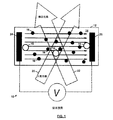
キャピラリーゾーン電気泳動、膜密閉定常状態電気泳動(membrane confined steady state electrophoresis)、ティセリウスの装置、およびレーザードップラー電気泳動(LDE)を含む電気泳動光散乱など、軟質試料の電気泳動移動度を測定するために用いられてきた技術が数多くある。LDEは、外部電界の印加下で粒子の動きを測定することによって、粒子の移動度を測定する。図1を参照すると、粒子16はバッファー14中に分散され、電極24および26は試料中に浸漬される。電界は非常に高いバッファー導電率で印加され、試料の分解は電極表面で生じ得る。また、タンパク質試料の場合、電極表面での酸化−還元反応がタンパク質構造内の結合をイオン化して凝集体18を生成し、その後、凝集体18は、電極表面に付着し、且つ試料の残部中に分散されると考えられる。LDEに典型的に伴う体積は、試料コストが高く、且つLDE測定の最適化を繰り返し行う必要があるため、問題となり得る。
(発明の概要)
一態様では、本発明は、分散剤を保持する容器を提供することと、分散剤中に浸漬された第1電極を提供することと、分散剤中に浸漬された第2電極を提供することとを含む、電気泳動測定法を特徴とする。第1電極と第2電極の間の分散剤内の位置に、両電極から分離された状態で試料が配置され、両電極にわたって交流電界を印加され、試料が時間的にコヒーレントな光で照射される。交流電界を印加する工程中に試料と相互作用した、照射する工程からの光において、周波数シフトを検出する。検出する工程の結果に基づいて、試料の特性を導出する。
(Field of Invention)
The present invention relates to a method and apparatus for performing electrophoretic measurements, including laser Doppler electrophoretic measurements using a diffusion barrier.
(Background of the Invention)
To measure the electrophoretic mobility of soft samples such as capillary zone electrophoresis, membrane confined steady state electrophoresis, electrophoretic light scattering, including Tisselius devices, and laser Doppler electrophoresis (LDE) There are many techniques that have been used in LDE measures particle mobility by measuring particle movement under the application of an external electric field. Referring to FIG. 1,
(Summary of Invention)
In one aspect, the present invention provides a container for holding a dispersant, providing a first electrode immersed in the dispersant, and providing a second electrode immersed in the dispersant. And an electrophoretic measurement method. A sample is placed in a position between the first electrode and the second electrode in a state separated from both electrodes, an AC electric field is applied across both electrodes, and the sample is irradiated with temporally coherent light. The A frequency shift is detected in the light from the irradiating step that interacted with the sample during the step of applying an alternating electric field. Based on the result of the detecting step, the characteristics of the sample are derived.
好ましい実施形態では、試料を配置する工程は、試料を注入することを含み得る。試料を配置する工程は、試料を容器内に引き込む過程の一部であり得る。前記方法は、さらに、試料を回収する工程を含み得る。試料は、軟質試料であり得る。試料は、タンパク質試料であり得る。試料を配置する工程は、分散剤によって電極から分離された位置に試料を配置することができる。試料を配置する工程は、分散剤とは異なるバリアによって電極から分離された位置に試料を配置することができる。導出する工程は、試料の電気泳動移動度値からゼータ電位値を導出することを含み得る。検出する工程は、交流が印加された状態で相当量の試料が第1および第2電極のいずれかまで拡散し得る時間よりも短い時間で行うことができる。照射する工程は、レーザーを使用することができる。 In preferred embodiments, placing the sample may include injecting the sample. Placing the sample can be part of the process of drawing the sample into the container. The method may further include the step of collecting the sample. The sample can be a soft sample. The sample can be a protein sample. In the step of arranging the sample, the sample can be arranged at a position separated from the electrode by the dispersant. In the step of arranging the sample, the sample can be arranged at a position separated from the electrode by a barrier different from the dispersant. Deriving can include deriving a zeta potential value from the electrophoretic mobility value of the sample. The detecting step can be performed in a time shorter than a time during which a considerable amount of sample can diffuse to either the first electrode or the second electrode in a state where an alternating current is applied. A laser can be used for the irradiation process.
別の態様では、本発明は、容器、第1電極、第2電極を含む、電気泳動装置を特徴とする。第1拡散バリアは、試料位置と第1電極との間に位置し、第2拡散バリアは、試料位置と第2電極との間に位置する。時間的にコヒーレントな照射光の光源は、試料位置を照射するように配置され、周波数シフト検出器は、試料と相互作用した後の試料位置からの照射光を受け入れるように配置される。 In another aspect, the invention features an electrophoresis apparatus that includes a container, a first electrode, and a second electrode. The first diffusion barrier is located between the sample position and the first electrode, and the second diffusion barrier is located between the sample position and the second electrode. A temporally coherent light source of illumination light is arranged to illuminate the sample location, and a frequency shift detector is arranged to accept illumination light from the sample location after interacting with the sample.
好ましい実施形態では、電気泳動装置は、さらに、容器内の試料位置に試料を導入するための試料導入チャネルを含み得る。試料導入チャネルは、針を含み得る。試料導入チャネルは、ポートを含み得る。電気泳動装置は、さらに、容器内の試料位置にある試料を抽出するための試料抽出チャネルを備えることを含み得る。第1拡散バリアは分散剤の体積を含むことができ、第2拡散バリアは分散剤の体積を含む。第1および第2拡散バリアは、導電性ゲルを含み得る。容器は、概ね直立したU字形の容器であり得る。U字形の容器は、U字形の容器の開口部に近接して開口部を有する試料導入ポートを含み得る。U字形の容器は、さらに、U字形の容器の開口部に近接して開口部を有する試料抽出ポートを含み得る。U字形の容器は、さらに、U字形の容器の開口部に近接してそれぞれ開口部を有する試料導入ポートおよび試料抽出ポートを含み得る。容器は、使い捨てのプラスチック容器であり得る。照射光源は、レーザーであり得る。電気泳動装置は、さらに、検出器によって測定された試料の電気泳動移動度値からゼータ電位値を導出するためのゼータ電位導出ユニットを含み得る。 In a preferred embodiment, the electrophoresis apparatus may further include a sample introduction channel for introducing a sample to a sample location within the container. The sample introduction channel can include a needle. The sample introduction channel may include a port. The electrophoretic device may further comprise providing a sample extraction channel for extracting a sample at a sample location within the container. The first diffusion barrier can include a volume of dispersant and the second diffusion barrier includes a volume of dispersant. The first and second diffusion barriers can include a conductive gel. The container may be a generally upright U-shaped container. The U-shaped container may include a sample introduction port having an opening proximate to the opening of the U-shaped container. The U-shaped container may further include a sample extraction port having an opening proximate to the opening of the U-shaped container. The U-shaped container may further include a sample introduction port and a sample extraction port each having an opening proximate to the opening of the U-shaped container. The container can be a disposable plastic container. The irradiation light source can be a laser. The electrophoresis apparatus may further include a zeta potential deriving unit for deriving a zeta potential value from the electrophoretic mobility value of the sample measured by the detector.
全体として、本文書は、拡散バリアの概念について述べる。この概念により、(分散されたまたはそれ以外の形態の)試料自体の小さな体積が、電極を含む、分散剤のみで予め充填されたより大きな体積に導入される。拡散バリアは、試料が分散されたバッファーを介して、電極表面との電気的接触を保ちながら試料を電極表面から隔離することが意図されている。LDE測定を行うのは、試料が電極に到達する前、またはより長い測定時間を必要とする場合には電極で生成された凝集体が光散乱検出体積内に戻る前が理想的である。また、この場合、試料体積は通常大幅に低減される。理想的には、試料は電極で分解されないため、測定を適切に最適化するために、著しく多くの測定を行うことが可能である。また、試料セルの物理的形態によっては、測定後に試料を回収することが可能である場合もある。また、本技術は、主としてタンパク質またはその他の軟質試料を対象としているが、電極の黒化を低減することによりセル寿命を延ばすために使用することもできる。 Overall, this document describes the concept of diffusion barriers. This concept introduces a small volume of the sample itself (dispersed or otherwise) into a larger volume that is pre-filled with only the dispersant, including the electrodes. The diffusion barrier is intended to isolate the sample from the electrode surface while maintaining electrical contact with the electrode surface through a buffer in which the sample is dispersed. The LDE measurement is ideally performed before the sample reaches the electrode or before the aggregates produced at the electrode return into the light scattering detection volume if a longer measurement time is required. Also, in this case, the sample volume is usually greatly reduced. Ideally, the sample is not decomposed by the electrode, so that significantly more measurements can be made to properly optimize the measurement. Further, depending on the physical form of the sample cell, it may be possible to recover the sample after the measurement. The technology is also primarily directed to proteins or other soft samples, but can also be used to extend cell life by reducing electrode blackening.
3ポートキュベット、4ポートキュベット、および現在提供されている折り曲げキャピラリーセル(folded capillary cell)(FCC)の独特な充填方法を含む、数多くの好ましい実施形態がある。これらのセルは全て、ゼータサイザーナノ(英国マルバーンに所在するマルバーン インストゥルメンツ リミテッド製)で見られるような標準的なキュベットホルダー用セルとして実施することができる。 There are a number of preferred embodiments, including a three-port cuvette, a four-port cuvette, and the unique filling method of currently provided folded capillary cells (FCC). All of these cells can be implemented as standard cuvette holder cells such as those found on Zetasizer Nano (Malvern Instruments Limited, Malvern, UK).
本発明のシステムは、タンパク質試料の電気泳動移動度測定における凝集体の生成を回避する助けになるという点で有利となり得る。これにより、凝集体の移動度はもとのタンパク質自体の移動度と非常に異なり得るため、これらの測定における誤差の原因が低減される可能性がある。電極の黒化は測定の質に何ら影響しないことを示している研究者らもいるが、この黒化は極度に外観が悪く、黒化は、業界の認識では、「汚れた」セル、したがって使用不能なセルを示すものとされている。 The system of the present invention may be advantageous in that it helps avoid the formation of aggregates in the electrophoretic mobility measurement of protein samples. This can reduce the source of errors in these measurements because the mobility of the aggregates can be very different from the mobility of the original protein itself. Some researchers have shown that the blackening of the electrode has no effect on the quality of the measurement, but this blackening is extremely bad in appearance, and blackening is, according to industry perception, a “dirty” cell, and therefore It is supposed to indicate an unusable cell.
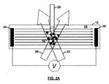
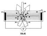
図2A〜2Dを参照すると、動作中、試料セルは、最初は、試料自体が分散されたバッファーのみで充填され、試料自体は充填されない(図2Aを参照)。試料は、検出体積近くの小さな領域にのみ添加され、測定が開始される。測定は、電気泳動移動度の正確な推定値を記録するために十分な時間行われるが(図2B〜2Dを参照)、試料が電極に到達するに十分なほど長くは行われない。これは、その後、電極凝集体の不存在下で、希釈されてはいるが、試料を取り出すことができることを意味する。 Referring to FIGS. 2A-2D, in operation, the sample cell is initially filled only with a buffer in which the sample itself is dispersed, and not the sample itself (see FIG. 2A). The sample is added only to a small area near the detection volume and the measurement is started. The measurement is performed for a time sufficient to record an accurate estimate of electrophoretic mobility (see FIGS. 2B-2D), but not long enough for the sample to reach the electrode. This means that the sample can then be removed, although diluted, in the absence of electrode aggregates.
図3を参照すると、電気泳動装置は、直立したU字形セル12Aをベースとすることができる。セル12Aの底部の光検出領域に試料16が注入される。これにより、拡散バリアとして機能するバッファーを保持するために、所与の占有面積について比較的長いチャネル長が提供される。拡散バリアは、試料が分散されたバッファーを介して、電極表面との電気的接触を保ちながら試料(タンパク質、軟質試料等)を電極表面から隔離し、電気泳動測定を行うことが意図されている。別の実施形態では、拡散をさらに妨げることができる寒天等の導電性ゲルプラグを、折り曲げセルチャネルに追加することができよう。
Referring to FIG. 3, the electrophoresis apparatus can be based on an upright
図4を参照すると、U字形電気泳動装置は、既存の光散乱測定システム、ゼータサイザーナノと適合するプラスチックセルとして実施することができる。ゼータサイザーナノは、英国マルバーンに所在するマルバーン インストゥルメンツ リミテッドから入手可能であり、本明細書に参照によって組み込まれる「ハイスループット懸濁液測定用装置(APPARATUS FOR HIGH−THROUGHPUT SUSPENSION MEASUREMENTS)」と題された国際公開第WO2010/041082号に記載されている。ゼータサイザーナノは、様々な種類の測定を行うことができるが、レーザードップラー電気泳動測定は、移動度測定に対して最も感度がよい。 Referring to FIG. 4, the U-shaped electrophoresis apparatus can be implemented as a plastic cell compatible with an existing light scattering measurement system, Zetasizer Nano. Zetasizer Nano is available from Malvern Instruments Limited, located in Malvern, UK, and is entitled “Apparatus For High-Through HPU SUSPENSION MEASUREMENTS”. International Publication No. WO2010 / 041082. Zetasizer Nano can perform various types of measurements, but laser Doppler electrophoresis measurements are most sensitive to mobility measurements.
レーザードップラー電気泳動測定では、レーザードップラー風速測定法の技術を使用して粒子の速度を測定する。移動する粒子によって生じる入射レーザービームの周波数シフトまたは位相シフトは、粒子移動度として測定される。この移動度は、分散剤粘度を入力し、且つスモルコフスキーまたはヒュッケルの理論を応用することにより、粒子のゼータ電位に変換することができる。これらの理論は、ほとんどの用途に有用な近似である。さらに正確な変換が可能な最新のモデルも入手可能であるが、分散の化学知識をより多く必要とする。 In laser Doppler electrophoresis measurements, the velocity of particles is measured using the laser Doppler anemometry technique. The frequency shift or phase shift of the incident laser beam caused by moving particles is measured as particle mobility. This mobility can be converted to the zeta potential of the particle by entering the dispersant viscosity and applying Smolkovsky or Hückel theory. These theories are useful approximations for most applications. Modern models that can be converted more accurately are also available, but they require more chemistry knowledge of dispersion.
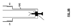
図5を参照すると、マルチポート折り曲げキャピラリーセル12Cを使用して、本発明の電気泳動測定を行うこともできる。基本概念を図5A〜5Dにまとめている。セルは4つのポートからなり、2つは希釈剤のみに用いられ(AおよびB)、2つは試料のみに用いられる(CおよびD)。3つのポートの場合は、ポートCおよびDの機能が1つにまとめられる。
Referring to FIG. 5, the electrophoretic measurement of the present invention can also be performed using a multiport folded
動作中は、セル12C全体が、試料が分散されたバッファーで充填される(図5A)。試料は試料カップC内に滴下(ピペットで移動)され、シリンジが試料を測定チャンバー内に引き込む(図5B)。直ちにLDE測定が開始される。測定が完了すると(図5C)、試料は何らかの形でセルアームに沿って拡散しているであろう。高速電界測定は、電極チャンバーから電極チャンバへの試料の電気浸透性の「スロッシング」に影響されないため、これらの電極チャンバーの頂部は開放されたままであり、希釈された形態ではあるが、試料をシリンジで回収することにより、セルがきれいに一掃される。(図5D)。図6を参照すると、マルチポートセルは、ゼータサイザーナノに都合のよい折り曲げ形態に設計することもできる。
During operation, the
図7を参照すると、特定の測定に必要な拡散バリアは、フィックの第一法則を使用して決定することができる。フィックの第一法則は、一定濃度供給源n(0)からの距離xにおける、時間tの、濃度nを記述しており、[数1]によって求められる。 Referring to FIG. 7, the diffusion barrier required for a particular measurement can be determined using Fick's first law. Fick's first law describes the concentration n at time t at a distance x from a constant concentration source n (0) and is given by [Equation 1].

式中、erfc()は、相補誤差関数であり、Dは、拡散係数である。ここでは、ゼータサイザーナノZSを使用して測定したD=120μm2/秒のリゾチームに焦点を当てる。 In the equation, erfc () is a complementary error function, and D is a diffusion coefficient. Here we focus on lysozyme with D = 120 μm 2 / sec measured using Zetasizer Nano ZS.
図7は、リゾチーム試料がx=0の供給源から30mmの距離を顕著に拡散するまでには多くの経過時間が必要であることを示している。マイクロ電気泳動を使用してタンパク質移動度測定を行うためにかかる時間は、約数分〜数十分である。これは、図7に示された時間尺度よりもかなり小さい。対流や残留電気浸透により図7に示された時間がかなり短くなる可能性は高いが、本技術の理論ベースを強調するための限界推定値としては十分である。即ち、試料を回収することが求められる場合、タンパク質が電極表面に移動するのにかかる時間内に、LDE測定を行うことができる。あるいは、タンパク質試料を損なうことなく回収することが求められない場合、タンパク質が電極に到達するまでにかかる時間と、その後のタンパク質/電極凝集体が電極から検出領域に戻るのにかかる時間の合計時間内に、LDE測定を行うことができる。 FIG. 7 shows that a lot of elapsed time is required for the lysozyme sample to significantly diffuse a distance of 30 mm from the x = 0 source. The time taken to perform protein mobility measurement using microelectrophoresis is about several minutes to several tens of minutes. This is much smaller than the time scale shown in FIG. Although the time shown in FIG. 7 is likely to be considerably shortened by convection and residual electroosmosis, it is sufficient as a limit estimate to emphasize the theoretical base of the present technology. That is, when it is required to collect the sample, LDE measurement can be performed within the time required for the protein to move to the electrode surface. Alternatively, if recovery of the protein sample is not required without damage, the total time taken for the protein to reach the electrode and the subsequent time for the protein / electrode aggregate to return from the electrode to the detection region Inside, LDE measurements can be made.
ここまで、多くの特定の実施形態に関連して、本発明を説明してきた。しかしながら、当業者であれば、本発明の範囲に包含されると考えられる多くの改変が明白であろう。例えば、セルの他の形状や、他の注入および/または抽出機構を考案することもできるであろうし、本発明の方法を他の種類の試料に適用することもできるであろう。したがって、本発明の範囲は、本明細書に添付される特許請求の範囲によってのみ制限されることが意図されている。加えて、特許請求の範囲の記載の順序は、特許請求の範囲における特定の用語の範囲を制限するものとして解釈されないものとする。 Thus far, the present invention has been described with reference to a number of specific embodiments. However, many modifications will be apparent to those skilled in the art that are deemed to fall within the scope of the invention. For example, other shapes of cells, other injection and / or extraction mechanisms could be devised, and the method of the present invention could be applied to other types of samples. Accordingly, it is intended that the scope of the invention be limited only by the claims appended hereto. In addition, the order of the claims is not to be construed as limiting the scope of certain terms in the claims.
Claims (24)
分散剤を保持する容器を提供する工程と、
前記分散剤中に浸漬された第1電極を提供する工程と、
前記分散剤中に浸漬された第2電極を提供する工程と、
前記第1電極と前記第2電極の間の分散剤内の位置に、前記第1電極および前記第2電極に向かって拡散できるように、最初は両電極から分離された状態で試料を配置する工程と、
前記第1電極および前記第2電極にわたって交流電界を印加する工程と、
前記試料の光散乱体積を時間的にコヒーレントな光で照射する工程と、
前記交流電界を印加する工程中に前記試料と相互作用した、前記照射する工程による光において周波数シフトを検出する工程と、
前記検出する工程の結果に基づいて、前記試料の特性を導出する工程と
を含み、前記検出する工程が、前記試料が第1電極および前記第2電極のいずれかまで拡散する前、又は、両電極において試料から生成された凝集体が光散乱体積内に戻る前に行われる、方法。 An electrophoretic measurement method comprising:
Providing a container holding a dispersant;
Providing a first electrode immersed in the dispersant;
Providing a second electrode immersed in the dispersant;
The sample is initially placed in a state between the first electrode and the second electrode, separated from both electrodes, so that it can diffuse toward the first electrode and the second electrode at a position in the dispersant. Process,
Applying an alternating electric field across the first electrode and the second electrode;
Irradiating light scattering volume of the sample with temporally coherent light;
Detecting a frequency shift in the light from the irradiating step interacting with the sample during the step of applying the alternating electric field;
Based on the results of the detecting step, and a step of deriving a characteristic of the sample, wherein the step of detecting is before the specimen is diffused to either the first electrode and the second electrode, or, The method is performed before the aggregates generated from the sample at both electrodes return into the light scattering volume.
第1アームおよび第2アームを有する、概ね直立したU字形の容器と、
前記第1アームの上端に位置する第1電極と、
前記第2アームの上端に位置する第2電極と、
前記第1電極および第2電極にわたって交流電界を印加する手段と、
試料位置と前記第1電極との間の第1拡散バリアと、
前記試料位置と前記第2電極との間の第2拡散バリアと、
前記試料位置の光散乱体積を照射するために配置される時間的にコヒーレントな照射光の光源と、
前記試料と相互作用した後の前記試料位置からの照射光を受け入れるように配置される周波数シフト検出器と
を含み、
前記装置が、前記交流電界を印加する手段により前記第1電極および第2電極にわたって電界が印加される間、前記試料の光散乱体積を照射するように構成され、
前記検出器が、
i)前記試料が前記第1電極および前記第2電極のいずれかまで拡散する前、又は
ii)前記第1電極および前記第2電極において生成された凝集体が移動して前記光散乱体積内に戻る前に、
散乱光における周波数シフトを検出するように構成される、装置。 An electrophoresis apparatus comprising:
A generally upright U-shaped container having a first arm and a second arm;
A first electrode located at an upper end of the first arm;
A second electrode located at an upper end of the second arm;
Means for applying an alternating electric field across the first electrode and the second electrode;
A first diffusion barrier between a sample position and the first electrode;
A second diffusion barrier between the sample position and the second electrode;
A temporally coherent light source disposed to irradiate a light scattering volume at the sample location;
A frequency shift detector arranged to receive illumination light from the sample location after interacting with the sample;
The apparatus is configured to irradiate a light scattering volume of the sample while an electric field is applied across the first electrode and the second electrode by means of applying the alternating electric field;
The detector is
i) before the specimen is diffused to any one of the first electrode and the second electrode, or ii) the first electrode and the second generated aggregates move in the electrode the light scattering volume in Before returning to
An apparatus configured to detect a frequency shift in scattered light.
Applications Claiming Priority (3)
| Application Number | Priority Date | Filing Date | Title |
|---|---|---|---|
| US12/972,412 US8702942B2 (en) | 2010-12-17 | 2010-12-17 | Laser doppler electrophoresis using a diffusion barrier |
| US12/972,412 | 2010-12-17 | ||
| PCT/US2011/065673 WO2012083272A1 (en) | 2010-12-17 | 2011-12-16 | Laser doppler electrophoresis using a diffusion barrier |
Related Child Applications (1)
| Application Number | Title | Priority Date | Filing Date |
|---|---|---|---|
| JP2016174957A Division JP6453285B2 (en) | 2010-12-17 | 2016-09-07 | Laser Doppler electrophoresis using diffusion barrier |
Publications (3)
| Publication Number | Publication Date |
|---|---|
| JP2013546003A JP2013546003A (en) | 2013-12-26 |
| JP2013546003A5 JP2013546003A5 (en) | 2015-01-29 |
| JP6006231B2 true JP6006231B2 (en) | 2016-10-12 |
Family
ID=45541066
Family Applications (2)
| Application Number | Title | Priority Date | Filing Date |
|---|---|---|---|
| JP2013544856A Active JP6006231B2 (en) | 2010-12-17 | 2011-12-16 | Laser Doppler electrophoresis using diffusion barrier |
| JP2016174957A Active JP6453285B2 (en) | 2010-12-17 | 2016-09-07 | Laser Doppler electrophoresis using diffusion barrier |
Family Applications After (1)
| Application Number | Title | Priority Date | Filing Date |
|---|---|---|---|
| JP2016174957A Active JP6453285B2 (en) | 2010-12-17 | 2016-09-07 | Laser Doppler electrophoresis using diffusion barrier |
Country Status (5)
| Country | Link |
|---|---|
| US (1) | US8702942B2 (en) |
| EP (1) | EP2652490B1 (en) |
| JP (2) | JP6006231B2 (en) |
| CN (1) | CN103339500B (en) |
| WO (1) | WO2012083272A1 (en) |
Families Citing this family (7)
| Publication number | Priority date | Publication date | Assignee | Title |
|---|---|---|---|---|
| US10648945B2 (en) * | 2010-12-17 | 2020-05-12 | Malvern Panalytical Limited | Laser doppler electrophoresis using a diffusion barrier |
| CA2974720A1 (en) | 2015-02-06 | 2016-08-11 | University Of Maryland, Baltimore | Tetra-specific, octameric binding agents and antibodies against clostridium difficile toxin a and toxin b for treatment of c. difficile infection |
| DE102015003019A1 (en) | 2015-03-06 | 2016-09-08 | Fraunhofer-Gesellschaft zur Förderung der angewandten Forschung e.V. | Method and device for the optical detection of movement in a biological sample with spatial extent |
| US10369582B2 (en) | 2015-04-30 | 2019-08-06 | Emissol Llc | System and method for spray visualization |
| US11130686B2 (en) | 2017-01-10 | 2021-09-28 | Vermeer Manufacturing Company | Systems and methods for dosing slurries to remove suspended solids |
| US20220155207A1 (en) | 2019-05-10 | 2022-05-19 | Aipore Inc. | Particle Identification Sensor and Particle Identification Device |
| JP7315257B2 (en) | 2019-10-11 | 2023-07-26 | アイポア株式会社 | Sensors, measuring instruments, computing devices and systems for particle identification |
Family Cites Families (20)
| Publication number | Priority date | Publication date | Assignee | Title |
|---|---|---|---|---|
| FR1583800A (en) * | 1967-05-29 | 1969-10-27 | ||
| US3766048A (en) * | 1972-11-24 | 1973-10-16 | Univ Illinois | Analysis of polymer mixtures in solution utilizing electrophoretic light scattering apparatus |
| US4101220A (en) * | 1977-03-31 | 1978-07-18 | General Electric Company | Laser Doppler spectroscopy with smoothened spectra line shapes |
| DE2852978C3 (en) * | 1978-12-07 | 1981-06-04 | Raimund Dr. 4005 Meerbusch Kaufmann | Device for the spectroscopic determination of the speed of particles moving in a liquid |
| JPS574546A (en) * | 1980-06-10 | 1982-01-11 | Shimadzu Corp | Measuring apparatus for electrophoresis of suspended particle |
| JP3472876B2 (en) * | 1993-06-07 | 2003-12-02 | コロイダル ダイナミックス プロプライエタリー リミテッド | Measurement of particle size and charge of multi-component colloids |
| HUP9801679A3 (en) * | 1995-03-10 | 2001-01-29 | Meso Scale Technologies Llc Co | Process and agent for multi-array, multi-specific electrochemiluminescence testing |
| JPH09292358A (en) * | 1996-02-29 | 1997-11-11 | Horiba Ltd | Zeta-potential measuring method using optical-scanning type two-dimensional concentration-distribution measuring device |
| US6406602B1 (en) | 1998-12-23 | 2002-06-18 | Genome Therapeutics Corporation | Sample loading device for gel electrophoresis |
| JP2001264282A (en) * | 2000-03-16 | 2001-09-26 | Kobe Steel Ltd | METHOD AND DEVICE FOR MEASURING ζ POTENTIAL ON METALLIC MATERIAL SURFACE AND SURFACE CHARACTERISTIC EVALUATION METHOD FOR METALLIC MATERIAL |
| GB2361772B (en) * | 2000-04-29 | 2004-05-19 | Malvern Instr Ltd | Mobility and effects arising from surface charge |
| US20020115198A1 (en) * | 2000-09-20 | 2002-08-22 | Nerenberg Michael I. | Microfabricated ultrasound array for use as resonant sensors |
| GB2368904A (en) | 2000-11-10 | 2002-05-15 | Zetatronics Ltd | Obtaining informatiion about zeta potential, electrophoretic mobility and numbers of suspended particles |
| JP2002360237A (en) * | 2001-06-08 | 2002-12-17 | Mitsubishi Chemicals Corp | Sample storage container |
| JP4334899B2 (en) | 2003-02-25 | 2009-09-30 | 大塚電子株式会社 | Electrophoretic velocity measuring device |
| JP2006177732A (en) * | 2004-12-21 | 2006-07-06 | Matsushita Electric Ind Co Ltd | Device and method for recovering biological substance |
| JP2006226981A (en) * | 2005-02-18 | 2006-08-31 | Microtec Nition:Kk | Simplified electrophoretic type zeta electrometer |
| JP2010101705A (en) * | 2008-10-22 | 2010-05-06 | Horiba Ltd | Instrument for measuring physical properties of particles |
| US8441638B2 (en) * | 2010-02-26 | 2013-05-14 | Wyatt Technology Corporation | Apparatus to measure particle mobility in solution with scattered and unscattered light |
| JP5363295B2 (en) * | 2009-09-01 | 2013-12-11 | 株式会社堀場製作所 | Zeta potential measurement cell and zeta potential measurement device |
-
2010
- 2010-12-17 US US12/972,412 patent/US8702942B2/en active Active
-
2011
- 2011-12-16 EP EP11813734.8A patent/EP2652490B1/en active Active
- 2011-12-16 CN CN201180060863.2A patent/CN103339500B/en active Active
- 2011-12-16 WO PCT/US2011/065673 patent/WO2012083272A1/en active Application Filing
- 2011-12-16 JP JP2013544856A patent/JP6006231B2/en active Active
-
2016
- 2016-09-07 JP JP2016174957A patent/JP6453285B2/en active Active
Also Published As
| Publication number | Publication date |
|---|---|
| WO2012083272A1 (en) | 2012-06-21 |
| JP2016200608A (en) | 2016-12-01 |
| JP6453285B2 (en) | 2019-01-16 |
| EP2652490A1 (en) | 2013-10-23 |
| JP2013546003A (en) | 2013-12-26 |
| CN103339500A (en) | 2013-10-02 |
| EP2652490B1 (en) | 2018-03-21 |
| CN103339500B (en) | 2016-01-20 |
| US20120152745A1 (en) | 2012-06-21 |
| US8702942B2 (en) | 2014-04-22 |
Similar Documents
| Publication | Publication Date | Title |
|---|---|---|
| JP6453285B2 (en) | Laser Doppler electrophoresis using diffusion barrier | |
| US11305283B2 (en) | Micro-fluidic devices for assaying biological activity | |
| JP6709299B2 (en) | Microfluidic device for assaying biological activity | |
| EP2721399B1 (en) | Surface charge measurement | |
| US10481128B2 (en) | Mass spectrometer and biological sample analysis method using said mass spectrometer | |
| BRPI0413213A (en) | method and apparatus for determining the presence of a selected analyte in a sample arranged in an electrochemical cell, method for determining the effective separation distance between a first electrode and a second electrode in an electrochemical cell, and method for determining an effective electrode transport property. a species in a liquid sample disposed between a first electrode and a second electrode in an electrochemical cell | |
| JP6864634B2 (en) | Systems and methods for electrophoretic separation and analysis of specimens | |
| JP2010008376A (en) | Sample separating and adsorbing instrument | |
| JP2002005888A (en) | Mobility and effect caused by surface charge | |
| US20230160851A1 (en) | Laser doppler electrophoresis using a diffusion barrier | |
| US20230073771A1 (en) | System and method for label-free single molecule detection | |
| EP3591377B1 (en) | Electrochemical determination of the permeability of biological membranes and cellular layers | |
| KR101324600B1 (en) | Hand-held diagnostic system using electrical parameter analysis | |
| WO2016158139A1 (en) | Electrical characteristic measurement device, electrical characteristic measurement method, blood condition analysis system, and electrical characteristic measurement program for computerizing said method | |
| JP2012211819A (en) | Biosensor | |
| JP2020122804A (en) | Micro-fluidic devices for assaying biological activity | |
| Misawa et al. | Cell array fluidic channel integrated with electrodes for cell-based multiple chemical sensing | |
| Chun et al. | Development and analysis of a microfluidic photothermal absorbance detector using polyelectrolytic gel electrodes |
Legal Events
| Date | Code | Title | Description |
|---|---|---|---|
| A521 | Request for written amendment filed |
Free format text: JAPANESE INTERMEDIATE CODE: A523 Effective date: 20141203 |
|
| A621 | Written request for application examination |
Free format text: JAPANESE INTERMEDIATE CODE: A621 Effective date: 20141203 |
|
| A977 | Report on retrieval |
Free format text: JAPANESE INTERMEDIATE CODE: A971007 Effective date: 20150715 |
|
| A131 | Notification of reasons for refusal |
Free format text: JAPANESE INTERMEDIATE CODE: A131 Effective date: 20150825 |
|
| A521 | Request for written amendment filed |
Free format text: JAPANESE INTERMEDIATE CODE: A523 Effective date: 20151117 |
|
| A131 | Notification of reasons for refusal |
Free format text: JAPANESE INTERMEDIATE CODE: A131 Effective date: 20160510 |
|
| A521 | Request for written amendment filed |
Free format text: JAPANESE INTERMEDIATE CODE: A523 Effective date: 20160711 |
|
| TRDD | Decision of grant or rejection written | ||
| A01 | Written decision to grant a patent or to grant a registration (utility model) |
Free format text: JAPANESE INTERMEDIATE CODE: A01 Effective date: 20160809 |
|
| A61 | First payment of annual fees (during grant procedure) |
Free format text: JAPANESE INTERMEDIATE CODE: A61 Effective date: 20160908 |
|
| R150 | Certificate of patent or registration of utility model |
Ref document number: 6006231 Country of ref document: JP Free format text: JAPANESE INTERMEDIATE CODE: R150 |
|
| R250 | Receipt of annual fees |
Free format text: JAPANESE INTERMEDIATE CODE: R250 |
|
| R250 | Receipt of annual fees |
Free format text: JAPANESE INTERMEDIATE CODE: R250 |
|
| R250 | Receipt of annual fees |
Free format text: JAPANESE INTERMEDIATE CODE: R250 |
|
| R250 | Receipt of annual fees |
Free format text: JAPANESE INTERMEDIATE CODE: R250 |
|
| R250 | Receipt of annual fees |
Free format text: JAPANESE INTERMEDIATE CODE: R250 |