JP6004185B2 - Vehicle seat structure - Google Patents
Vehicle seat structure Download PDFInfo
- Publication number
- JP6004185B2 JP6004185B2 JP2013051833A JP2013051833A JP6004185B2 JP 6004185 B2 JP6004185 B2 JP 6004185B2 JP 2013051833 A JP2013051833 A JP 2013051833A JP 2013051833 A JP2013051833 A JP 2013051833A JP 6004185 B2 JP6004185 B2 JP 6004185B2
- Authority
- JP
- Japan
- Prior art keywords
- seat
- seat cushion
- cushion frame
- rib
- vehicle
- Prior art date
- Legal status (The legal status is an assumption and is not a legal conclusion. Google has not performed a legal analysis and makes no representation as to the accuracy of the status listed.)
- Expired - Fee Related
Links
Images


Description
本発明は、車両のシート構造に係わり、特に、シートクッション、シートバック及びヘッドレストを有する車両用シートのシート構造に関する。 The present invention relates to a vehicle seat structure, and more particularly to a vehicle seat structure having a seat cushion, a seat back, and a headrest.
近年、燃費向上や操縦安定性のニーズから、車両のさらなる軽量化が求められており、シートについても軽量化が求められている。ここで、シートを構成するシートクッションやシートバックなどの部品の骨格として、通常、金属で形成されるシートクッションフレームやシートバックフレームが設けられており、これらの重量を低減するために、極力計量な材料にてそれらのフレームを構成することや、フレーム自体の板厚を小さくするという様々な工夫が行われている。 In recent years, there has been a demand for further weight reduction of vehicles due to needs for improved fuel consumption and handling stability, and also weight reduction of seats. Here, the seat cushion frame and seat back frame made of metal are usually provided as the skeleton of the parts such as the seat cushion and seat back that make up the seat. In order to reduce the weight of these parts, weigh as much as possible. Various ideas have been made to construct these frames with various materials and to reduce the thickness of the frames themselves.
一方、車両のシートに求められる要件として、シートそのものの性能としての乗員の姿勢保持機能や快適性の確保に加え、車両の衝突時に、乗員の安全性を確保することが求められる。例えば、車両の前突時には、シートベルトやエアバッグなどの乗員拘束装置と協働して適切に乗員をシートに拘束し、乗員の安全性を確保するために、衝突時に乗員からシートに伝わる荷重によって、シート自体が変形しないようにする必要がある。 On the other hand, as a requirement required for a vehicle seat, in addition to ensuring a passenger's posture maintaining function and comfort as the performance of the seat itself, it is required to ensure the safety of the passenger in the event of a vehicle collision. For example, in the event of a frontal collision of a vehicle, a load transmitted from the occupant to the seat at the time of a collision in order to properly restrain the occupant to the seat in cooperation with an occupant restraint device such as a seat belt or airbag, and to ensure the safety of the occupant Therefore, it is necessary to prevent the sheet itself from being deformed.
ここで、特許文献1には、後突時、シートバックフレームからリクライニング装置を介してシートクッションサイドフレームに伝達される荷重に対して、シートクッションサイドフレームの板厚を部分的に変更し、それにより、所定の箇所を意図的に塑性変形させて後突時の衝撃吸収を行い、重量の増加を伴うことなく、乗員の安全性を確保しようとする技術が開示されている。
Here, in
しかしながら、特許文献1に開示された技術では、フレーム自体の板厚を薄くした部分は一部分であり、さらなる軽量化の余地がある一方、前突時のシートにかかる荷重を考慮したものではなく、乗員の安全性をより確保する必要がある、という問題がある。
However, in the technique disclosed in
また、前突時、シートベルトによる乗員拘束に関して考慮すべき観点の一つに、いわゆるサブマリン現象の防止がある。このサブマリン現象とは、前突時に乗員の身体がシートに対して前方に移動する慣性力を受け、乗員がシートベルトとシートクッションとの間をすり抜けて、シートの座面から前方に滑り落ちしまう現象をいう。このようなサブマリン現象を抑制するため、前突時、シートクッションの着座面の前方部分が下方に変位することを抑制する必要がある。ところが、近年のシートの軽量化の要請に応えるため、従来のシート構造のまま、シートクッションフレーム全体の板厚を減少させると、シートクッション着座面の前方部分の下方への変位を十分に抑制出来ず、サブマリン現象を抑制することが出来ない懸念がある。 In addition, one of the viewpoints to be considered regarding passenger restraint by a seat belt at the time of a front collision is prevention of a so-called submarine phenomenon. This submarine phenomenon receives the inertial force that the occupant's body moves forward with respect to the seat at the time of a front collision, and the occupant slips between the seat belt and the seat cushion and slides forward from the seat surface of the seat. A phenomenon. In order to suppress such a submarine phenomenon, it is necessary to suppress that the front part of the seating surface of a seat cushion is displaced below at the time of a front collision. However, in order to meet the recent demand for weight reduction of seats, if the plate thickness of the entire seat cushion frame is reduced while maintaining the conventional seat structure, the downward displacement of the front portion of the seat cushion seating surface can be sufficiently suppressed. Therefore, there is a concern that the submarine phenomenon cannot be suppressed.
本発明は、上述した従来技術の問題点を解決するためになされたものであり、シートクッションフレーム全体の板厚の減少を可能としつつ、サブマリン現象を抑制することが出来る車両用シート構造を提供することを目的とする。 The present invention has been made in order to solve the above-described problems of the prior art, and provides a vehicle seat structure capable of suppressing the submarine phenomenon while allowing the thickness of the entire seat cushion frame to be reduced. The purpose is to do.
上記の目的を達成するために、本発明は、シートクッション、シートバック及びヘッドレストを備えた車両用シート構造であって、所定の板厚を有する板材で形成されると共にその上面及び下面にそれぞれフランジ面が形成され、シートクッション内に設けられたシートクッションフレームと、着座した乗員の荷重を支えるようシートクッションフレームの前方部分に設けられ、その側部の上面にフランジ面が形成され、このフランジ面とシートクッションフレームの上面のフランジ面とが複数箇所で固定されることにより、シートクッションフレームに固定されるようになっているシートパンと、シートクッションフレームを車両のフロアに固定するための固定部材と、を有し、シートクッションフレームには、この固定部材を取り付けるための取付部が形成されると共にこの取付部の上方で上下方向に延びる第1リブが形成され、シートクッションフレームの前方部分に設けられたシートパンは、少なくとも第1リブが形成された部分の上方部分で且つシートクッションフレームに固定される複数箇所の少なくとも1つが位置する箇所でシートクッションフレームに固定されており、シートクッションフレームには、第1リブが形成されていない部分に、その一部を切り欠いて形成されたシート構成部品を固定する固定部が形成され、シートクッションフレームには、シートクッションフレームの上面のフランジ面及び/又は下面のフランジ面の近傍で且つ固定部の上方及び/又は下方に、シートクッションフレームの長手方向に延びる第2リブが形成されていることを特徴としている。
このように構成された本発明においては、シートクッションフレームには、シートクッションフレームを車両のフロアに固定するための固定部材を取り付けるための取付部が形成されると共にこの取付部の位置の上方で上下方向に延びる第1リブが形成され、シートパンは、少なくとも第1リブが形成された部分の上方部分でシートクッションフレームに取り付けられているので、前突時、シートパンからシートクッションフレームに有効に乗員の荷重を伝達させ、そのほぼ上下方向の荷重に対して第1リブが耐力を発揮して、シートクッションフレームの上下方向の変形が抑制され、これにより、シートパンを含むシートクッションの前方部分が下方に変位することを抑制することが出来る。従って、シートクッションフレーム全体の板厚の減少を可能としつつ、サブマリン現象を抑制することが出来る。
さらに、本発明においては、シート構成部品の固定部をシートクッションフレームを切り欠くことにより形成されているので、切り欠きの分、重量の軽減を図ることが出来ると共に、そのような切り欠きを形成した分のシートクッションフレームの剛性の低下を第2リブにて補うことが出来る。
To achieve the above object, the present invention is a seat cushion, a seat structure for a vehicle having a seat back and head rest, respectively Rutotomoni its upper and lower surfaces are formed of a plate material having a predetermined thickness flange The seat cushion frame provided in the seat cushion and the front portion of the seat cushion frame to support the load of the seated occupant, and the flange surface is formed on the upper surface of the side portion. A seat pan that is fixed to the seat cushion frame by fixing the upper surface of the seat cushion frame and the flange surface on the upper surface of the seat cushion frame, and a fixing member for fixing the seat cushion frame to the vehicle floor And attaching this fixing member to the seat cushion frame A first rib extending in the vertical direction is formed above the mounting portion, and the seat pan provided in the front portion of the seat cushion frame is at least a portion where the first rib is formed. at least one of the plurality of locations and is fixed to the seat cushion frame in the upper part but is secured to the seat cushion frame at a point located in the seat cushion frame, the portion where the first rib is not formed, a part The seat cushion frame is formed with a fixing portion for fixing the seat component, and the seat cushion frame includes a flange surface on the upper surface and / or a flange surface on the lower surface of the seat cushion frame and above the fixing portion and / or or downward, and wherein the second rib extending in the longitudinal direction of the seat cushion frame is formed To have.
In the present invention configured as described above, the seat cushion frame is formed with an attachment portion for attaching a fixing member for fixing the seat cushion frame to the floor of the vehicle, and above the position of the attachment portion. The first rib extending in the vertical direction is formed, and the seat pan is attached to the seat cushion frame at the upper part of at least the portion where the first rib is formed. The first rib exerts proof strength against the load in the substantially vertical direction, and the vertical deformation of the seat cushion frame is suppressed, whereby the front of the seat cushion including the seat pan is controlled. It is possible to suppress the portion from being displaced downward. Therefore, the submarine phenomenon can be suppressed while the thickness of the entire seat cushion frame can be reduced.
Furthermore, in the present invention, since the fixing portion of the seat component is formed by cutting out the seat cushion frame, the weight can be reduced by the amount of the cutout, and such a cutout is formed. The second rib can compensate for the reduced rigidity of the seat cushion frame.
本発明によれば、シートクッションフレーム全体の板厚を減少させて軽量化を図りつつ、サブマリン現象を抑制することが出来る。 According to the present invention, the submarine phenomenon can be suppressed while reducing the thickness of the entire seat cushion frame to reduce the weight.
次に、添付図面により、本発明の実施形態による車両用シート構造を説明する。
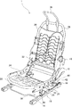
先ず、図1乃至図3により、本発明の実施形態による車両用シート構造の全体構成を説明する。図1は、本発明の実施形態による車両用シート構造の外観構成を斜め左前方且つ上方から見た斜視図であり、図2は、本発明の実施形態による車両用シート構造を斜め左前方且つ上方から見た斜視図であり、図3は、本発明の実施形態による車両用シート構造を側方から見た側面図である。
Next, a vehicle seat structure according to an embodiment of the present invention will be described with reference to the accompanying drawings.
First, the overall configuration of a vehicle seat structure according to an embodiment of the present invention will be described with reference to FIGS. 1 to 3. FIG. 1 is a perspective view of an external configuration of a vehicle seat structure according to an embodiment of the present invention as viewed obliquely from the left front and above, and FIG. 2 illustrates the vehicle seat structure according to an embodiment of the present invention as a diagonally left front and It is the perspective view seen from the upper part, and FIG. 3 is the side view which looked at the vehicle seat structure by embodiment of this invention from the side.
先ず、図1に示すように、本実施形態による車両用シート1は、シートクッション2、シートバック4及びヘッドレスト6を有する。本実施形態では、シート1は、その幅方向が車幅方向と一致するように車両前後方向に向けて設けられる。
シートクッション2の左右両側には、シートの下部を覆うトリム部材8が設けられ、また、シート左側には、乗員がそれぞれ手動で操作するようになっている、シートクッション2を上下移動させるためのリフトレバー10と、シートバック4をリクライニングさせるためのリクライニングレバー12及びランバーサポートレバー13とが設けられている。
First, as shown in FIG. 1, the
Trim members 8 that cover the lower part of the seat are provided on both the left and right sides of the
次に、図1乃至図3に示すように、シート1の左右両側の車体フロア(図示せず)には、車両前後方向に延び、シートクッション2をシート前後方向(車両前後方向)に摺動自在に支持するスライド機構14がそれぞれ設けられている。これらのスライド機構14は、フロアに固定されるガイドレール16と、これらのガイドレール16に対して摺動可能に係合するスライダ18とで主に構成されている。スライド機構14には、接続ブラケット20等が設けられている。
Next, as shown in FIGS. 1 to 3, the vehicle body floors (not shown) on the left and right sides of the
次に、図2及び図3に示すように、シート1は、シートクッション2内に設けられ、シートクッション2自体を支持するための左右一対のシートクッションフレーム24及びこれらのシートクッションフレーム24のシート前方部分に固定されるシートパン26と、シートバック内に設けられ、シートバック4自体を支持するためのシートバックフレーム28、及び、サスペンションマット30、支持用ばね部材32と、ヘッドレスト6が取り付けられると共にヘッドレスト6を支持し、ヘッドレスト6の上下方向位置を調節可能に構成されているヘッドレストフレーム36と、を有している。
Next, as shown in FIGS. 2 and 3, the
また、本実施形態によるシート1は、スライド機構14のスライダ18と、シートクッションフレーム24とを接続し、シート1を支持しつつ、シートクッション2を上下移動させるためのリフト機構38が設けられている。このリフト機構38は、図2及び図3に示すように、シート前方部分に設けられる左右一対の前方リンク部材40と、後方側リンク機構42を有する。
前方リンク部材40は、その下端部が接続ブラケット20に回動自在に連結され、その上端部がシートクッションフレーム24に回動自在に連結されている。接続ブラケット20は、スライダ18に固定されている。
Further, the
The
後方側リンク機構42は、シート後方部分に設けられる左右一対の後方リンク部材44及び接続ブラケット46と、を有する。
前方リンク部材40及び後方リンク部材44は、本実施形態では、接続ブラケット20、ブラケット46、スライド機構14を介して、シートクッションフレーム24を車両のフロアに固定するための部材として機能している。また、本実施形態では、シートクッションフレーム24は、各リンク部材40、44が回動することにより、シートクッション2が上下移動可能になっている。
なお、本実施形態は、変形例として、シートクッションの高さ位置が一定の位置に固定されるシートにも適用可能である。
The rear
In the present embodiment, the
In addition, this embodiment is applicable also to the sheet | seat by which the height position of a seat cushion is fixed to a fixed position as a modification.
次に、図4及び図5により、シートパン26、シートクッションフレーム24及びリンク部材40の構造について説明する。
図4は、本発明の実施形態による車両用シート構造のシートクッションフレームの周辺構造を斜め左後方から見た部分拡大斜視図であり、図5は、本発明の実施形態による車両用シート構造のシートクッションフレームの周辺構造を左側から見た部分拡大側面図である。なお、以下では、図4及び図5に示すようなシート左側の構成を主に説明するが、シート右側の構成も同様であるので、ここではその説明を省略する。
Next, the structure of the
FIG. 4 is a partially enlarged perspective view of the peripheral structure of the seat cushion frame of the vehicle seat structure according to the embodiment of the present invention viewed obliquely from the left rear, and FIG. 5 is the vehicle seat structure according to the embodiment of the present invention. It is the partial expanded side view which looked at the periphery structure of a seat cushion frame from the left side. In the following, the configuration on the left side of the seat as shown in FIGS. 4 and 5 will be mainly described, but the configuration on the right side of the seat is also the same, and thus the description thereof is omitted here.
先ず、図3に示すように、シートパン26は、主に乗員の太腿の荷重を支持するようシートクッション2の前方部分に設けられている。このシートパン26は、底面26aを有し、図示しないクッション部材の一部を収容するようその底面26aを3方の壁部26bで取り囲むような凹型に形成されている。左右の壁部26bからは、シートクッションフレーム24の上部に延びるフランジ部26cが形成されている。これらのフランジ部26cは、左右それぞれ2箇所づつ、シートクッションフレーム24の上部にリベット50により取り付けられ、これにより、シートパン26がシートクッションフレーム24に固定されている。シートパン26にかかる乗員の荷重は、主にフランジ部26c及びリベット50を介してシートクッションフレーム24に伝達されるようになっている。ここで、図4及び図5に示すように、シートパン26のフランジ部26cは、その前端部分から、シートクッションフレーム24の後述する第1リブ54が形成された上方部分を覆う範囲まで延び、シートクッションフレーム24に固定される。なお、シートパン26は、シートクッションフレーム24に溶接等により固定するようにしても良い。
First, as shown in FIG. 3, the
次に、図3及び図4に示すように、シートクッションフレーム24には、上述した前方リンク部材40の回動軸52を取り付けるための孔(図示せず)が形成された取付部53が形成されている。回動軸52及び前方リンク40は、前突時のシートクッション2の前方部分の荷重を支持するような強度及び剛性を有するよう構成されている。また、シートパン26も同様に、前突時のシートクッション2の前方部分の荷重を支持するような強度及び剛性を有するよう構成されている。
Next, as shown in FIGS. 3 and 4, the
次に、シートクッションフレーム24は、所定の板厚(例えば1.2mm)を有する板状部材を一体成型して形成されている。図4及び図5に示すように、このようなシートクッションフレーム24には、上述した取付部53と、上述したリベット50のうち後方側のリベット50とを結ぶように上下方向に延びる上下方向リブ(第1リブ)54が形成されている。この上下方向リブ54は、前突時、シートパン26から伝達される荷重に対して耐力を発揮するよう、シートクッションフレーム24の側面部を部分的にシート幅方向外方に盛り上げるように形成されており、その剛性が部分的に高められている。
Next, the
また、シートクッションフレーム24には、その全体の剛性を高めるよう、上縁部に、シートクッションフレーム24の長手方向に延びる長手方向リブ(第2リブ)56が形成されている。また、下縁部にも、同様に長手方向に延びる長手方向リブ(第2リブ)58が形成されている。なお、これらのような長手方向リブ56、58は、シートクッションフレーム24が所定の剛性を保てるのであれば、上縁部又は下縁部のいずれか一方に形成しても良い。
Further, the
また、シートクッションフレーム24には、シート構成部品である、シート表皮やネットや上述したトリム部材8等を取り付けるためのフック用切り欠き(固定部)60、62が形成されている。これらのフック用切り欠き60、62は、シートクッションフレーム24の側面部の一部を切り欠いて形成されている。これら切り欠き60、62は、シート構成部品の固定部としても機能するため、別途固定部を設ける必要がないこと、また、それら自体が切り欠かれて形成されているので、部品点数の削減及びシート全体の軽量化に寄与している。
The
次に、図6により、上述したように構成されたシート構造における、前突時の荷重伝達経路について説明する。図6は、前突時の荷重伝達経路を説明するための図5と同様に示す図である。
まず、前突時、特に、その衝突後期、乗員の主に太腿がシート前方部分に作用し、その荷重はシートパン26の主に後端部分に伝達される。このシートパン26に伝達された荷重は、上述したシートパン26のフランジ部26cを介してシートクッションフレーム24に伝達され、シートクッションフレーム24には、図6中Fで示すような向きの荷重が加わる。この荷重Fは、前方リンク部材40にて支持される。このように、シートクッションフレーム24は、シート前方部分から前方リンク部材40への荷重伝達経路の一部となる。より具体的には、シートクッションフレーム24に加わる荷重Fは、側面視で、取付部53から見て上方のシートクッションフレーム24の上縁部分の一部分(本実施形態では、主に後方側のリベット50の部分)から、取付部53へと向かう方向に伝達される。
Next, the load transmission path at the time of the front collision in the seat structure configured as described above will be described with reference to FIG. FIG. 6 is a view similar to FIG. 5 for explaining the load transmission path at the time of the front collision.
First, at the time of a front collision, particularly in the late stage of the collision, the thigh of the occupant mainly acts on the front part of the seat, and the load is transmitted mainly to the rear end part of the
次に、本発明の実施形態によるシート構造の作用効果を説明する。
本実施形態においては、シートクッションフレーム24には、シートクッションフレーム24を車両のフロアに固定するための前方リンク部材40を取り付けるための取付部53が形成されると共にこの取付部53の位置の上方で上下方向に延びる上下方向リブ54が形成され、シートパン26は、少なくとも第1リブ54が形成された部分の上方部分でシートクッションフレーム24に固定されているので、前突時、シートパン26からシートクッションフレーム24に有効に乗員の荷重を伝達させ、そのほぼ上下方向の荷重に対して上下方向リブ54が耐力を発揮して、シートクッションフレーム24の上下方向の変形が抑制され、これにより、シートパン26を含むシートクッション2の前方部分が下方に変位することを抑制することが出来る。従って、シートクッションフレーム24全体の板厚の減少(例えば、1.4mmから1.2mmへの板厚変更)を可能としつつ、サブマリン現象を抑制することが出来る。
Next, the effect of the sheet structure according to the embodiment of the present invention will be described.
In the present embodiment, the
また、本実施形態においては、シート構成部品の固定部であるフック用切り欠き60をシートクッションフレームを切り欠くことにより形成されているので、その切り欠きの分、重量の軽減を図ることが出来る、また、そのような切り欠き60を形成した分のシートクッションフレーム24の剛性の低下を長手方向リブ56、58にて補うことが出来る。
Further, in the present embodiment, since the
1 シート
2 シートクッション
16 ガイドレール
18 スライダ
20 接続ブラケット
24 シートクッションフレーム
26 シートパン
26c シートパンの固定用フランジ部
40 前方リンク部材(固定部材)
50 リベット
52 前方リンク部材の回動軸
53 回動軸の取付部
54 上下方向リブ(第1リブ)
56 上縁側の長手方向リブ(第2リブ)
58 下縁側の長手方向リブ(第2リブ)
60 フック用切り欠き(固定部)
DESCRIPTION OF
50
56 Longitudinal rib on the upper edge side (second rib)
58 Longitudinal rib on the lower edge (second rib)
60 Notch for hook (fixed part)
Claims (1)
所定の板厚を有する板材で形成されると共にその上面及び下面にそれぞれフランジ面が形成され、上記シートクッション内に設けられたシートクッションフレームと、
着座した乗員の荷重を支えるよう上記シートクッションフレームの前方部分に設けられ、その側部の上面にフランジ面が形成され、このフランジ面と上記シートクッションフレームの上面のフランジ面とが複数箇所で固定されることにより、上記シートクッションフレームに固定されるようになっているシートパンと、
上記シートクッションフレームを車両のフロアに固定するための固定部材と、を有し、 上記シートクッションフレームには、この固定部材を取り付けるための取付部が形成されると共にこの取付部の上方で上下方向に延びる第1リブが形成され、
上記シートクッションフレームの前方部分に設けられたシートパンは、少なくとも上記第1リブが形成された部分の上方部分で且つ上記シートクッションフレームに固定される複数箇所の少なくとも1つが位置する箇所で上記シートクッションフレームに固定されており、
上記シートクッションフレームには、上記第1リブが形成されていない部分に、その一部を切り欠いて形成されたシート構成部品を固定する固定部が形成され、
上記シートクッションフレームには、上記シートクッションフレームの上面のフランジ面及び/又は下面のフランジ面の近傍で且つ上記固定部の上方及び/又は下方に、シートクッションフレームの長手方向に延びる第2リブが形成されていることを特徴とする車両用シート構造。 A vehicle seat structure including a seat cushion, a seat back, and a headrest,
Predetermined plate is formed of a plate material having a thickness Rutotomoni each flange surface on its upper and lower surfaces are formed, and the seat cushion frame provided in the seat cushion,
Provided in the front part of the seat cushion frame to support the load of the seated occupant , a flange surface is formed on the upper surface of the side part, and this flange surface and the flange surface on the upper surface of the seat cushion frame are fixed at multiple places by being a seat pan that is adapted to be fixed to the seat cushion frame,
A fixing member for fixing the seat cushion frame to the floor of the vehicle, and the seat cushion frame is formed with an attachment portion for attaching the fixing member and above and below the attachment portion. A first rib extending to
The seat pan provided in the front portion of the seat cushion frame is at least an upper portion of the portion where the first rib is formed and at a position where at least one of a plurality of locations fixed to the seat cushion frame is located. It is fixed to the cushion frame,
The seat cushion frame is formed with a fixing portion for fixing a seat component formed by cutting out a part of the first rib in a portion where the first rib is not formed.
The seat cushion frame has second ribs extending in the longitudinal direction of the seat cushion frame in the vicinity of the upper flange surface and / or the lower flange surface of the seat cushion frame and above and / or below the fixing portion. A vehicle seat structure characterized by being formed .
Priority Applications (1)
| Application Number | Priority Date | Filing Date | Title |
|---|---|---|---|
| JP2013051833A JP6004185B2 (en) | 2013-03-14 | 2013-03-14 | Vehicle seat structure |
Applications Claiming Priority (1)
| Application Number | Priority Date | Filing Date | Title |
|---|---|---|---|
| JP2013051833A JP6004185B2 (en) | 2013-03-14 | 2013-03-14 | Vehicle seat structure |
Publications (2)
| Publication Number | Publication Date |
|---|---|
| JP2014177184A JP2014177184A (en) | 2014-09-25 |
| JP6004185B2 true JP6004185B2 (en) | 2016-10-05 |
Family
ID=51697589
Family Applications (1)
| Application Number | Title | Priority Date | Filing Date |
|---|---|---|---|
| JP2013051833A Expired - Fee Related JP6004185B2 (en) | 2013-03-14 | 2013-03-14 | Vehicle seat structure |
Country Status (1)
| Country | Link |
|---|---|
| JP (1) | JP6004185B2 (en) |
Families Citing this family (2)
| Publication number | Priority date | Publication date | Assignee | Title |
|---|---|---|---|---|
| CN109383339A (en) * | 2017-08-11 | 2019-02-26 | 上汽通用五菱汽车股份有限公司 | A kind of integrated seat |
| CN114435210A (en) * | 2020-11-02 | 2022-05-06 | 宝钢金属有限公司 | Lightweight car seat skeleton |
Family Cites Families (3)
| Publication number | Priority date | Publication date | Assignee | Title |
|---|---|---|---|---|
| JP4128799B2 (en) * | 2002-01-16 | 2008-07-30 | 古河電気工業株式会社 | Seat weight sensor |
| JP5408688B2 (en) * | 2008-05-28 | 2014-02-05 | 株式会社デルタツーリング | Sheet |
| JP2013035523A (en) * | 2011-08-10 | 2013-02-21 | Ts Tech Co Ltd | Mounting structure for mounting load measurement sensor |
-
2013
- 2013-03-14 JP JP2013051833A patent/JP6004185B2/en not_active Expired - Fee Related
Also Published As
| Publication number | Publication date |
|---|---|
| JP2014177184A (en) | 2014-09-25 |
Similar Documents
| Publication | Publication Date | Title |
|---|---|---|
| JP6141736B2 (en) | Vehicle seat | |
| WO2012086803A1 (en) | Vehicle seat | |
| EP2606770A1 (en) | Seat cushion shell unit and shell-type seat for vehicle | |
| JP5846391B2 (en) | Vehicle seat structure | |
| JP4388575B2 (en) | Vehicle seat | |
| JP5669567B2 (en) | Vehicle seat | |
| JP5483557B2 (en) | Vehicle seat | |
| JP6004185B2 (en) | Vehicle seat structure | |
| JP2024045684A (en) | vehicle seat | |
| US9663009B2 (en) | Conveyance seat | |
| JP5695915B2 (en) | Vehicle seat | |
| JP4019744B2 (en) | Sheet | |
| JP2022179712A (en) | vehicle seat | |
| JP5989856B2 (en) | Vehicle seat | |
| JP6627931B2 (en) | Vehicle seat | |
| JP5932007B2 (en) | Vehicle seat | |
| JP5629204B2 (en) | Vehicle seat | |
| JP6240276B2 (en) | Vehicle seat | |
| JP6658304B2 (en) | Vehicle seat | |
| JP2012056455A (en) | Seat for vehicle | |
| JP5753614B2 (en) | Vehicle seat | |
| JP7332955B2 (en) | vehicle seat | |
| JP7433575B2 (en) | vehicle seat | |
| JP2013193568A (en) | Vehicle seat | |
| JP5629205B2 (en) | Vehicle seat |
Legal Events
| Date | Code | Title | Description |
|---|---|---|---|
| A621 | Written request for application examination |
Free format text: JAPANESE INTERMEDIATE CODE: A621 Effective date: 20150312 |
|
| A977 | Report on retrieval |
Free format text: JAPANESE INTERMEDIATE CODE: A971007 Effective date: 20160129 |
|
| A131 | Notification of reasons for refusal |
Free format text: JAPANESE INTERMEDIATE CODE: A131 Effective date: 20160210 |
|
| A521 | Request for written amendment filed |
Free format text: JAPANESE INTERMEDIATE CODE: A523 Effective date: 20160411 |
|
| TRDD | Decision of grant or rejection written | ||
| A01 | Written decision to grant a patent or to grant a registration (utility model) |
Free format text: JAPANESE INTERMEDIATE CODE: A01 Effective date: 20160810 |
|
| A61 | First payment of annual fees (during grant procedure) |
Free format text: JAPANESE INTERMEDIATE CODE: A61 Effective date: 20160823 |
|
| R150 | Certificate of patent or registration of utility model |
Ref document number: 6004185 Country of ref document: JP Free format text: JAPANESE INTERMEDIATE CODE: R150 |
|
| LAPS | Cancellation because of no payment of annual fees |