JP6001999B2 - Airfoil, compressor, vane, gas turbine engine, and stator row - Google Patents
Airfoil, compressor, vane, gas turbine engine, and stator row Download PDFInfo
- Publication number
- JP6001999B2 JP6001999B2 JP2012236241A JP2012236241A JP6001999B2 JP 6001999 B2 JP6001999 B2 JP 6001999B2 JP 2012236241 A JP2012236241 A JP 2012236241A JP 2012236241 A JP2012236241 A JP 2012236241A JP 6001999 B2 JP6001999 B2 JP 6001999B2
- Authority
- JP
- Japan
- Prior art keywords
- end wall
- airfoil
- radial deviation
- average
- circumferential direction
- Prior art date
- Legal status (The legal status is an assumption and is not a legal conclusion. Google has not performed a legal analysis and makes no representation as to the accuracy of the status listed.)
- Active
Links
Images


Classifications
-
- F—MECHANICAL ENGINEERING; LIGHTING; HEATING; WEAPONS; BLASTING
- F01—MACHINES OR ENGINES IN GENERAL; ENGINE PLANTS IN GENERAL; STEAM ENGINES
- F01D—NON-POSITIVE DISPLACEMENT MACHINES OR ENGINES, e.g. STEAM TURBINES
- F01D5/00—Blades; Blade-carrying members; Heating, heat-insulating, cooling or antivibration means on the blades or the members
- F01D5/12—Blades
- F01D5/14—Form or construction
- F01D5/141—Shape, i.e. outer, aerodynamic form
- F01D5/142—Shape, i.e. outer, aerodynamic form of the blades of successive rotor or stator blade-rows
- F01D5/143—Contour of the outer or inner working fluid flow path wall, i.e. shroud or hub contour
-
- F—MECHANICAL ENGINEERING; LIGHTING; HEATING; WEAPONS; BLASTING
- F05—INDEXING SCHEMES RELATING TO ENGINES OR PUMPS IN VARIOUS SUBCLASSES OF CLASSES F01-F04
- F05D—INDEXING SCHEME FOR ASPECTS RELATING TO NON-POSITIVE-DISPLACEMENT MACHINES OR ENGINES, GAS-TURBINES OR JET-PROPULSION PLANTS
- F05D2250/00—Geometry
- F05D2250/70—Shape
- F05D2250/73—Shape asymmetric
-
- F—MECHANICAL ENGINEERING; LIGHTING; HEATING; WEAPONS; BLASTING
- F05—INDEXING SCHEMES RELATING TO ENGINES OR PUMPS IN VARIOUS SUBCLASSES OF CLASSES F01-F04
- F05D—INDEXING SCHEME FOR ASPECTS RELATING TO NON-POSITIVE-DISPLACEMENT MACHINES OR ENGINES, GAS-TURBINES OR JET-PROPULSION PLANTS
- F05D2250/00—Geometry
- F05D2250/70—Shape
- F05D2250/74—Shape given by a set or table of xyz-coordinates
-
- Y—GENERAL TAGGING OF NEW TECHNOLOGICAL DEVELOPMENTS; GENERAL TAGGING OF CROSS-SECTIONAL TECHNOLOGIES SPANNING OVER SEVERAL SECTIONS OF THE IPC; TECHNICAL SUBJECTS COVERED BY FORMER USPC CROSS-REFERENCE ART COLLECTIONS [XRACs] AND DIGESTS
- Y02—TECHNOLOGIES OR APPLICATIONS FOR MITIGATION OR ADAPTATION AGAINST CLIMATE CHANGE
- Y02T—CLIMATE CHANGE MITIGATION TECHNOLOGIES RELATED TO TRANSPORTATION
- Y02T50/00—Aeronautics or air transport
- Y02T50/60—Efficient propulsion technologies, e.g. for aircraft
Description
本発明は概ねターボ機械に関し、特にガスタービンエンジンの圧縮機、タービン、またはファンセクションのステータベーンに関する。特に本発明は、軸方向および周方向端壁輪郭(contour)を成形したステータベーンエーロフォイルに関する。 The present invention relates generally to turbomachines and more particularly to compressor, turbine or fan section stator vanes of gas turbine engines. In particular, the present invention relates to a stator vane airfoil molded with axial and circumferential end wall contours.
ガスタービンエンジンは航空機や産業用発電を含む広範囲の応用例に信頼性の高い高効率の動力を提供する。現代の設計は、通常、上流のインレットと下流の排気口とともに流れに対して直列に配置された、圧縮機と、燃焼器と、タービンセクションとからなる出力コアを中核として作られる。 Gas turbine engines provide reliable and efficient power for a wide range of applications including aircraft and industrial power generation. Modern designs are typically built around an output core consisting of a compressor, combustor, and turbine section, arranged in series with the upstream inlet and downstream outlets in series.
圧縮機セクションがインレットからの空気を圧縮し、燃焼器内で燃料と混合し、点火して、高温燃焼ガスを発生させる。タービンセクションは、膨張する燃焼ガスからエネルギーを抽出し、共通のシャフトを通して圧縮機を駆動する。シャフトにおける回転エネルギーの形態、排気からの反応スラストの形態、又はその両方の形態でエネルギーが伝えられる。 A compressor section compresses air from the inlet, mixes it with fuel in the combustor, and ignites to generate hot combustion gases. The turbine section extracts energy from the expanding combustion gases and drives the compressor through a common shaft. Energy is transferred in the form of rotational energy in the shaft, in the form of reactive thrust from the exhaust, or both.
小規模のガスタービンエンジンは概ね同時回転する圧縮機セクションとタービンセクションとを有する1スプール設計を利用する。より大規模の燃焼タービン、ジェットエンジン、および産業用ガスタービン(IGT)は通常、異なる圧力および温度で作動し、異なるスピードで回転する複数の同軸状に入れ子にされたスプールに配置される。 Small scale gas turbine engines utilize a one spool design with a compressor section and a turbine section that rotate generally simultaneously. Larger combustion turbines, jet engines, and industrial gas turbines (IGTs) are typically placed in a plurality of coaxially nested spools that operate at different pressures and temperatures and rotate at different speeds.
各スプール内の個別の圧縮機セクションおよびタービンセクションは、ロータブレードとステータベーンエーロフォイルとの交互の列を形成する複数の段に更に分割される。エーロフォイルは作動流体の流れを回転させ、タービン内の回転エネルギーに変換するように揚力を発生させる形状をなす。 The individual compressor and turbine sections within each spool are further divided into a plurality of stages that form alternating rows of rotor blades and stator vane airfoils. The airfoil is shaped to generate lift to rotate the working fluid flow and convert it to rotational energy in the turbine.
航空応用例はターボジェット、ターボファン、ターボプロップ、およびターボシャフト形態を有する。ターボジェットは古い設計であり、主に排気から推力を発生する。現代の固定翼航空機は通常ターボファンおよびターボプロップエンジンを利用し、低圧スプールが推力ファンまたはプロペラに連結される。ターボシャフトエンジンはヘリコプタを含む回転翼航空機で用いられる。 Aviation applications have turbojet, turbofan, turboprop, and turboshaft configurations. The turbojet is an old design that generates thrust mainly from the exhaust. Modern fixed wing aircraft typically utilize a turbofan and turboprop engine, and a low pressure spool is connected to a thrust fan or propeller. Turboshaft engines are used in rotary wing aircraft including helicopters.
これらの異なるガスタービン応用例を通じて、エンジン性能はステータベーンエーロフォイルに亘る正確な流れ制御に大きく依存する。同様に、流れ制御はエーロフォイル設計だけに依存するのではなく、エーロフォイル表面に隣接する、フローダクトの内側端壁と外側端壁に沿って画定された、隣接する流路の構造にも依存する。 Through these different gas turbine applications, engine performance is highly dependent on precise flow control across the stator vane airfoil. Similarly, flow control is not only dependent on the airfoil design, but also on the structure of adjacent flow paths defined along the inner and outer end walls of the flow duct adjacent to the airfoil surface. To do.
本発明はステータまたはベーンエーロフォイルに関する。エーロフォイルは、前縁から後縁へと軸方向に延在するとともに基部から先端部へと径方向に延在する、正圧面と、負圧面と、を有する。基部および先端部が、それらの間に平均翼幅(mean span)を画定する。 The present invention relates to a stator or vane airfoil. The airfoil has a pressure surface and a suction surface that extend axially from the leading edge to the trailing edge and radially extend from the base to the tip. The base and tip define a mean span between them.
内側端壁がエーロフォイルの基部から軸方向かつ周方向に延在して、内側端壁輪郭を画定する。外側端壁が先端部から軸方向かつ周方向に延在して、外側端壁輪郭を画定する。 An inner end wall extends axially and circumferentially from the base of the airfoil to define an inner end wall profile. An outer end wall extends axially and circumferentially from the tip to define an outer end wall profile.
内側端壁輪郭および外側端壁輪郭のうち少なくとも一つが非軸対称である。特に、その輪郭は、公称端壁半径からの非軸対称の径方向偏差によって定義され、公称半径は、周方向に一定であり、径方向偏差は、公称半径に関して軸方向と周方向の両方において、平均翼幅の少なくとも3%変動する。 At least one of the inner end wall contour and the outer end wall contour is non-axisymmetric. In particular, its contour is defined by a non-axisymmetric radial deviation from the nominal end wall radius, where the nominal radius is constant in the circumferential direction and the radial deviation is both axial and circumferential with respect to the nominal radius. Fluctuates by at least 3% of the average blade width.
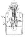
図1は航空機の推進機関として用いられる2スプールターボファンの形態の、ガスタービンエンジン10の断面図である。図に示すように、低スプール12は、低圧シャフト18を介して回転するように連結された低圧圧縮機(LPC)14と、低圧タービン(LPT)16と、を含む。高スプール20は、高圧シャフト26を介して回転するように連結された高圧圧縮機(HPC)22と、高圧タービン(HPT)24と、を含む。高スプール20は、エンジン中心線(すなわちタービン軸)CLに沿って、燃焼器28が高圧圧縮機22と高圧タービン24との間に流れに対して直列に配置されるように、低スプール12の周りに同軸に配置される。
FIG. 1 is a cross-sectional view of a
ナセル30が、ガスタービンエンジン10の前端の周りに配置され、その径方向内側表面にファンケース31が推進ファン32からファン出口案内翼(FEGV)33へと延在する。ファン32にファンシャフト34が回転するように連結され、ファンダクト(すなわちバイパスダクト)35を通して推進流れFを発生させる。高性能のエンジン設計では、ファンドライブギアシステム36がファンシャフト34を低スプール12に連結して、騒音を低減し運転効率を向上させるための独立したファンスピードコントロールを提供する。
A
図1に示すように、ガスタービンエンジン10は、低スプール12、高スプール20、低圧タービン16、高圧タービン24、およびファン出口案内翼33全体に亘って分散されたステータベーン段すなわちステータベーンの列を含む。これらのベーンの列は、これに限定しないが、ファンロータ32のファン出口案内翼33、低圧圧縮機14および高圧圧縮機22の圧縮機出口案内翼37,38、および低圧タービン16または高圧タービン24のタービンベーンの列39を含む。一方、ガスタービンエンジン10は、上述のように、1つ、2つ、3つ、またはそれ以上の同時回転するまたは二重反転するスプールを有するターボファン、ターボプロップ、ターボジェット、またはターボシャフトエンジンとして、または、多軸の産業用ガスタービンとして構成され、それに応じて個々のベーンの列33,37,38,39の数、位置、および構成は異なる。
As shown in FIG. 1, the
各ベーンの列は、複数の個々のベーンエーロフォイルを、タービン軸CLを中心として周方向に配置することによって画定される。内側および外側端壁は低圧圧縮機14、低圧タービン16、高圧圧縮機22、高圧タービン24、およびターボファン形態では、バイパスダクト(またはファンダクト)35を通してフローダクトを画定する。追加のベーンの列が個々の圧縮機とタービンセクションとの間に配置された移行ダクトに配置される。
Column of each vane is defined by placing a plurality of individual vane airfoils, circumferentially about the turbine axis C L. The inner and outer end walls define a flow duct through a bypass duct (or fan duct) 35 in the
効率およびスラスト性能を向上させるように、一つ以上のこれらのベーンの列に非軸対称の端壁輪郭(non axis−symmetric endwall contouring)が設けられる。この技術では、流体の剥離の一因となる二次流れおよび端壁のロールアップの影響を低減するように、内側端壁および外側端壁の輪郭がタービン軸CLを中心として軸方向に異なるだけでなく、周方向にも異なる。このアプローチはまた、以下に記載するように全体的な拡散性能(diffusion capability)を向上させる。 One or more rows of these vanes are provided with non-axis-symmetric endwall contouring to improve efficiency and thrust performance. In this technique, the contours of the inner and outer end walls are axially different about the turbine axis C L so as to reduce the effects of secondary flow and end wall rollup that contribute to fluid separation. Not only in the circumferential direction. This approach also improves overall diffusion capability, as described below.
図2は、二次流れ場を示す、ステータの列(ベーンの列またはベーンの段)40の周方向の図である。ステータの列40は、タービン軸CLを中心として周方向に配置された複数の個々のステータベーンエーロフォイル42の形状をなす。流脈線(streakline)Sは径方向外径(OD)端壁または径方向内径(ID)端壁44,43に沿った二次流れを表す。
FIG. 2 is a circumferential view of a stator row (vane row or vane stage) 40 showing the secondary flow field. Row of
流れは、図2の左側から右側へと進み、ガスタービン軸CLに沿った概ね下流軸方向(矢印F)に、個々のエーロフォイルセクション42の前縁45から後縁46へと進む。流脈線Sは、例えば染料注入によって示される、特定の空間点を通流した流体成分の位置を表す。一方、瞬間的な流れの方向を表す、流れの方向の接線である、流線(streamline)が用いられてもよく、あるいは、特定の流体粒子が続く軌跡に沿って指向された流跡線(pathline)によって流れ場が表される、あるいは、一組の流体粒子をマーキングし、時間が経つに従ってのその変位を追跡することにより形成されるタイムライン(time line)を用いてもよい。
Flow proceeds from the left side of FIG. 2 to the right, in a generally downstream direction (arrow F) along the gas turbine axis C L, the process proceeds to the
エーロフォイルセクション(すなわちエーロフォイル部)42を径方向外側に見た図を示し、(±x軸に沿った)タービン軸CLから径方向(+z軸)に端壁44に向かって見ているところを示す。個々のエーロフォイル部42は凸面(負圧面)47と凹面(正圧面)48との間に画定され、前縁45から後縁46へと軸方向に延在する。端壁44はエーロフォイル部の間に画定され、隣り合う負圧面47と正圧面48との間に(±y軸に沿って)周方向に延在する。
The airfoil section (i.e. airfoil portion) 42 shows a view radially outward, looking toward the end wall 44 (along the ± x-axis) radially from the turbine axis C L (+ z axis) Where. Each
一般的な設計では、端壁44は、ベーンエーロフォイル部またはブレードエーロフォイル部を形成するようにエーロフォイル部42に取り付けられた、隣り合うプラットフォーム面に沿って形成される。代替例として、エーロフォイル部42はプラットフォーム面を有さず、独立して形成され、端壁44に取り付けられる。したがって、ここで定義したように、表面44はエーロフォイル部42の基部または先端部から軸方向および周方向に延在する内側または外側プラットフォームに沿って形成される内側または外側端壁表面であり、エーロフォイル部42の基部または先端部から軸方向および周方向に延在する内側または外側端壁を形成する内側または外側プラットフォーム面である。
In a typical design, the
翼形中心線Cは、負圧面47と正圧面48との間の中間点である、エーロフォイルプロファイルの平均線を画定する。周方向流路幅Wは、隣り合うエーロフォイル42の翼形中心線Cの間に画定され、タービン軸CLを中心として内径または外径端壁44に沿って周方向に測定される。
The airfoil centerline C defines the average line of the airfoil profile, which is the midpoint between the
図2に示すように、ベーンエーロフォイル42は流れ場における渦流を低減するように成形される。特に、エーロフォイル42は、主に軸方向下流の流脈線S´を、ベーンの列40の右側に生じさせるように、上流流脈線Sの周方向成分をベーンの列40の左側に向ける。
As shown in FIG. 2, the
ある一定の拡散係数または流れの旋回レベル以上では、境界流層の肥厚化や剥れ、およびその他の損失効果により非効率な旋回を呈しうる。付加的な端壁境界層の流れや関連する二次流れの影響により、損失効果が内径および外径端壁の付近で合成される。ベーンエーロフォイル42によって生成される流路横断(cross−passage)圧力勾配および低流れ方向速度もまた隣り合うエーロフォイル42の間に流路を横断する流れを生じさせ、渦巻運動状態(vorticity)と端壁のロールアップ(roll−up)を生じさせる。これらの影響により、後縁46で始まりエーロフォイル42の負圧面47に沿って上流に進む、内径および外径端壁における隅部の剥離の一因となる。
Above a certain diffusion coefficient or flow swirl level, an inefficient swirl can be exhibited due to thickening and flaking of the boundary flow layer and other loss effects. Loss effects are combined near the inner and outer diameter endwalls due to the additional endwall boundary layer flow and associated secondary flow effects. The cross-passage pressure gradient and low flow direction velocity generated by the
これらの影響に対処するように、ベーンの列40に非軸対称の端壁輪郭(endwall contouring)が設けられる。特に、端壁44の輪郭はエンジン中心線CL(±x軸)に沿った軸方向と、中心線CLを中心として±y軸に沿って回転する周方向と、の両方における径方向の偏差(variation)によって画定される。一方、以下に述べるように、非軸対称の輪郭が内側端壁、または内側および外側端壁の両方に適用され、輪郭が形成されていない軸対称の形状と比較してステータ性能を向上させる。
To address these effects, the
図3Aは、輪郭が形成されていないすなわち軸対称の径方向内径および径方向外径端壁53,54を有するエーロフォイル52の側面図である。流れは前縁55の流脈線Sに沿ってエーロフォイル52の方に向けられ、主に軸方向(矢印F)である。負の軸流速度の領域Rは、後縁56に沿った隅部の剥離および端壁のロールアップに起因し、負圧面57の下流領域へと延在する。
FIG. 3A is a side view of an
図3Aに示すように、エーロフォイル52は、周方向(±y軸)に沿って均一な一定の公称内側および外側半径を有する、軸対称の内径および外径端壁(すなわちプラットフォーム)53,54を有する。この設計は、後縁56と、内径および外径端壁53,54と、の間の隅部の接合部分で、特に重負荷下で、実質的な流体の剥離を受けやすい。境界層のロールアップは逆軸流の広範な領域Rを生み出し、負圧面57に沿った流動的損失(flow dynamic loss)を増大させる。
As shown in FIG. 3A, the
エーロフォイル52に湾曲(bow)を加えることにより隅部の剥離の進行を遅らせうるが、これは翼幅の間の負荷性能(loading capability)を犠牲にして成り立つ。一方、非軸対称の端壁輪郭では、端壁に沿った二次流れの影響を緩和し、負荷時の実質的な負の影響を受けることなく全体的な拡散性能を向上させることが可能である。
Adding a bow to the
図3Bは、ある一定の形状が付けられた内径および外径端壁(すなわちプラットフォーム)43,44を有するエーロフォイル42の側面図である。流れはまた流脈線Sに沿って前縁45から後縁46へとエーロフォイル42の方に向けられ、主に軸方向(矢印F)である。しかしながら、図3Bに示すように、負の軸流速度の領域Rは、図3Aの輪郭が形成されていない(すなわち軸対称の)設計に比べて実質的に減少している。また内径および外径端壁43,44に沿った隅部の剥離が減少しており、端壁43,44から負圧面47にかけての境界層ロールアップが減少している。
FIG. 3B is a side view of
エーロフォイル42を周方向から見た図で示し、負圧面47に向かって−y軸に沿って見下ろしている。軸方向の翼弦長Lは前縁45と後縁46との間でエンジン中心線(x軸)に沿って画定される。
The
概ね、軸方向翼弦長Lは、エーロフォイル42の基部49と先端部50との間で径方向(+z軸)に沿って変化する。平均軸方向翼弦は内径および外径における翼弦の値の平均によって与えられる。
Generally, the axial chord length L varies between the base 49 and the

翼幅高さ(span height)Hは、内径端壁(すなわち径方向内径プラットフォーム)43に隣接する基部49から、外径端壁(すなわち径方向外径プラットフォーム)44に隣接する先端部50へと、径方向(+z軸)に沿って画定される。翼幅高さHは軸方向(±x軸)に沿って変化し、平均翼幅(mean span)は前縁45における高さと後縁46における高さとの平均によって与えられる。
The span height H extends from the base 49 adjacent to the inner diameter end wall (ie, radial inner diameter platform) 43 to the
一方、平均翼幅および平均軸方向翼弦長は、例えば、エーロフォイル42の基部49と先端部50との中間に位置する平均ブレードセクションを用いることにより、すなわち内径端壁43と外径端壁44との平均翼幅の半分における平均ブレードセクションを用いることにより、同時に画定される。
On the other hand, the average blade width and the average axial chord length are obtained by using, for example, an average blade section located between the base 49 and the
ステータの列40およびエーロフォイル42の形態は応用分野に応じて異なる。一部のエーロフォイル42では、平均翼幅は約0.4インチ(1.0cm)〜1.2インチ(3.0cm)もしくはそれ以上、例えば0.60±0.05インチ、すなわち1.50±0.10cmである。対応するベーンの列40は約5インチ(12cm)〜15インチ(38cm)もしくはそれ以上の範囲の周方向に一定の公称内側半径(RID)を有し、例えば7.5±0.5インチ、すなわち19±1cmである。周方向に一定の公称外側半径(ROD)は約6インチ(15cm)〜18インチ(45cm)もしくはそれ以上の範囲に亘り、例えば8.0±0.5インチ、すなわち20±1cmである。エーロフォイル42の翼幅の中間(midspan)、またはフローダクトの中心すなわち内側半径RIDと外側半径RODとの中間に定義される平均フローダクト半径(RM)もまた異なる。
The configuration of the
内径端壁43の輪郭は、エンジン中心線(またはタービン軸)から測定した、一定の公称内側端壁半径RIDの周りの周方向の偏差(variation)によって定義される。同様に、外径端壁44の輪郭は、一定の公称外側端壁半径RODの周りの周方向の偏差によって定義される。径方向の偏差は±Z軸に沿って、流路の中心に向かってまたは流路の中心から離れる方向に測定され、それに応じて流量範囲が減少もしくは増加する。流路の中心は翼幅の中心(平均翼幅の半分)で定義され、平均半径RMは内径端壁43と外径端壁44との中間に位置する。
The contour of the inner
図3Bに示すように、±x軸に沿った軸方向位置の関数として、および±y軸に沿った周方向位置の関数として、内径端壁43および外径端壁44のうちの一つまたは両方の輪郭が変化する。その結果、エーロフォイル42はエンジン軸CLを中心とした回転に関して非対称な内径端壁輪郭または外径端壁輪郭のうちの少なくとも一つを有する。
As shown in FIG. 3B, one of the inner
この設計により、エーロフォイル42の負圧面47に亘る逆軸流の領域Rを減少させる。後縁46と、内径/外径端壁43,44と、の間の隅部の接合部分で、特にエーロフォイル42の高負荷下において、流体の剥離が低減される。特に基部49と先端部50との間の翼幅の中間部分における端壁のロールアップもまた後縁46に沿って低減される。
This design reduces the reverse axial flow region R across the
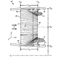
図4A,4Bは、非軸対称の輪郭を示す、ベーンの列40の内径端壁43および外径端壁44の輪郭のプロットを示す。ベーンの列40をそれぞれ±Z軸に沿った径方向内側および径方向外側の図で示す。翼形中心線Cが図4Aの内径端壁43に隣接するエーロフォイル基部49、および図4Bの外径端壁44に隣接するエーロフォイル先端部50に定義される。
4A and 4B show plots of the contours of the inner
負圧面47および正圧面48がガスタービン中心線に沿って、前縁45の軸方向翼弦L0%から後縁46の軸方向翼弦L100%へと軸方向に延在する。内径端壁43が隣り合うエーロフォイル42の基部49の間に周方向に延在し、ベーン間の流路幅Wが翼形中心線C(流路幅0%)から定義されるとともに、+y軸方向に負圧面47から隣接する正圧面48へと増大する。
A
留意すべきは、流路幅Wは湾曲した翼形中心線Cの間で定義されるため、図4Aおよび図4Bの座標系は必ずしも直交座標すなわちデカルト座標である必要は無い。内径端壁43または外径端壁44に点を配置すべく、前縁45(軸方向翼弦L0%)と後縁46(軸方向翼弦L100%)との間に相対的な軸方向翼弦Lが識別され、翼形中心線Cに対して周方向(エンジン軸に対して垂直方向)に延在する。次いで、隣り合う翼形中心線Cの間で周方向流路幅Wが測定され、このとき50%流路幅Wが常に、その隣り合った翼形中心線Cの曲線に従う隣り合ったエーロフォイル42の間の中間点となるように測定される。従って、50%流路幅地点(および流路幅Wのその他の値)は、軸方向翼弦寸法Lに沿った翼形中心線Cの曲率により定義される、エーロフォイル部42の形状に基づいて軸方向に変化する。
It should be noted that since the channel width W is defined between the curved airfoil center lines C, the coordinate systems of FIGS. 4A and 4B do not necessarily have to be Cartesian or Cartesian coordinates. Relative axial blades between leading edge 45 (axial chord L0%) and trailing edge 46 (axial chord L100%) to place points on inner
図4A,4Bの端壁輪郭は、内径端壁43の表1に記載され、外径端壁44の表2に記載されているように定められた離散的な制御点数に基づく。制御点は、平均エーロフォイル翼幅高さの割合として、および、相対的な軸方向翼弦L(または割合)と相対的なベーン間の流路幅W(または割合)との関数として与えられ、周方向に一定の公称内径半径または外径半径からの端壁輪郭の偏差を決定する。
The end wall contours of FIGS. 4A and 4B are based on discrete control points determined as described in Table 1 of the inner
図4Aの表1では、軸方向翼弦長Lおよび翼形中心線Cはそれぞれ内径端壁43に隣接するエーロフォイル42の基部49に沿って画定される。周方向流路幅Wは、隣り合う翼形中心線Cの間に画定され、内径端壁43に沿って測定されるとともに負圧面47から正圧面48に向かって増加する。負の値(−)が大きくなるほど、エンジン中心線またはガスタービン軸に向かって、周方向に一定の内径公称半径より下に(エーロフォイル42の翼幅の中間における)流路の中間から離れる方向に逸脱した径方向特徴部を表す。正の値(+)が大きくなるほど、ガスタービン軸から離れる方向に翼幅の中間に向かって、周方向に一定の内径公称半径上または内径公称半径より上にある、径方向特徴部を表す。
In Table 1 of FIG. 4A, the axial chord length L and the airfoil centerline C are each defined along the
図4Bの表2では、軸方向翼弦長Lおよび翼形中心線Cは先端部50に沿って画定され、周方向流路幅Wは外径端壁44に沿って周方向に測定される。また負の値(−)が大きくなるほど、翼幅の中間における流路の中間から離れる方向、すなわち外径公称半径よりも上にガスタービン軸から離れる方向に逸脱する特徴部を示す。正の値(+)が大きくなるほど、外径公称半径上または外径公称半径より下、すなわちガスタービン軸および翼幅の中間に向かう方向に逸脱する特徴部を示す。
In Table 2 of FIG. 4B, the axial chord length L and the airfoil centerline C are defined along the
したがって、負の値は、表1および表2の両方において、翼幅の中間から離れる方向に延在する径方向特徴部を示し、内径端壁43と外径端壁44との間の流量範囲を増加させる傾向がある。一方、正の値が大きくなるほど、径方向に翼幅の中間に向かって延在する特徴部を示し、流量範囲を減少させる。
Therefore, a negative value indicates a radial feature extending away from the middle of the blade width in both Table 1 and Table 2, and the flow range between the inner
表1,2に示すように、内径端壁43および外径端壁44の両方の端壁輪郭は、隣り合うエーロフォイル42の負圧面47と正圧面48との間に配置された物理的な点の、軸方向と周方向の両方における、平均翼幅の少なくとも3%の径方向偏差で定義される。ある地点では、径方向偏差は平均翼幅の5または6%以上である。
As shown in Tables 1 and 2, the end wall contours of both the inner
一部のベーン22では、内径および外径の輪郭はそれぞれ実質的に表1および表2に示された一組の径方向偏差の値に対応する。内径および外径端壁の輪郭の両方とも、高温または低温、あるいはコーティングされたまたはコーティングされていない表面で表されてもよい。 For some vanes 22, the inner and outer diameter profiles substantially correspond to the set of radial deviation values shown in Tables 1 and 2, respectively. Both the inner and outer diameter end wall contours may be represented by hot or cold, or a coated or uncoated surface.
一方、一部のベーン22は、概して一連の特徴部に対してスプラインフィットまたは多項式フィッティングを採用するのではなく、内径または外径輪郭の1つ以上の個々の特徴部を組み込む。例えば、内径端壁43に沿って、軸方向翼弦Lの25%〜50%の間と、周方向流路幅Wの25%〜75%の間とに位置する、平均翼幅の5%を上回る径方向偏差を有する特徴部が存在する。さらに具体的には、この特徴部は、軸方向翼弦Lの約30±10%と周方向流路幅Wの約50±10%に中心がある最大偏位(deflection)を有する。
On the other hand, some vanes 22 generally incorporate one or more individual features of an inner or outer diameter profile rather than employing a spline fit or polynomial fitting for a series of features. For example, along the inner
外径端壁44に沿って、軸方向翼弦Lの50%〜75%の間と、周方向流路幅Wの75%〜100%の間とに位置する、平均翼幅の5%を上回る径方向偏差を有する特徴部が存在する。さらに具体的には、この特徴部は、軸方向翼弦Lの約70±10%と周方向流路幅Wの約85±10%とに中心がある最大偏位を有する。別の外径特徴部は、軸方向翼弦Lの約25±10%と周方向流路幅Wの約20±10%に中心がある、平均翼幅の5%を上回る最大偏位を有する。
Along the outer
留意すべきは、負圧面47および正圧面48に沿って異なる輪郭を形成する非軸対称のフィットを組み込むように、流路幅Wの0%および100%の制御点は必ずしも等しいまたは断続的である必要はない。さらに、周方向流路幅Wの0%および100%の制御点は、両方とも翼形中心線上にあり、これはエーロフォイル部42内部にある。一方、物理的な端壁面は、隣り合うエーロフォイル部42の間の負圧面47から正圧面48へと延在する。
It should be noted that the 0% and 100% control points of the channel width W are not necessarily equal or intermittent so as to incorporate a non-axisymmetric fit that forms different contours along the
したがって、実質的な対応は、ここで用いるように、隣り合うエーロフォイル42の負圧面47と正圧面48との間に配置された、表1,2における実際の(物理的な)制御点との実質的な対応を意味する。また実質的な対応は、例えば制御点に固定(anchored)した三次スプラインを用いることによる、制御点の一式への多項式フィットまたはスプラインフィットを含む。これらの応用例では、端壁の輪郭は実質的に一つのエーロフォイル42の負圧面47と、隣接するエーロフォイル42の正圧面48との間のフィッティング関数(fitting function)に対応するが、必ずしもエーロフォイル自体の断面内にある必要はない。
Thus, the substantial correspondence, as used herein, is the actual (physical) control point in Tables 1 and 2 located between the
さらに、実質的な対応は、実際の(物理的な)制御点およびフィット関数に関する、例えば平均翼幅の1または2%の公称公差を含む。もう一つの選択肢として、公差は例えば2,5〜10mil、すなわち、0.002、0.005または0.010インチ以内、または約0.05、0.10、または0.25mm以内のように絶対的である。 Furthermore, the substantial correspondence includes a nominal tolerance of, for example, 1 or 2% of the average span, with respect to the actual (physical) control points and the fit function. As another option, the tolerance is absolute, for example, within 2-5-10 mils, ie within 0.002, 0.005 or 0.010 inches, or within about 0.05, 0.10, or 0.25 mm. Is.
実施例を参照しながら本発明を説明したが、本発明の範囲を逸脱することなく様々な変更がなされ、本発明の要素と同等のものに置き換えられうることが当業者にとって理解されるであろう。さらに、本発明の真の範囲を逸脱することなく特定の状況もしくは材料に適合するように、種々の変更が本発明の教示に対してなされうる。したがって、本発明は開示の特定の実施例に限定されるものではなく、付記の特許請求の範囲に含まれる全ての実施例を包含することを意図するものである。 Although the present invention has been described with reference to exemplary embodiments, those skilled in the art will recognize that various modifications can be made and replaced with equivalent elements of the present invention without departing from the scope of the invention. Let's go. In addition, various modifications may be made to the teachings of the invention to adapt to a particular situation or material without departing from the true scope of the invention. Accordingly, the present invention is not intended to be limited to the particular embodiments disclosed, but is intended to embrace all embodiments that fall within the scope of the appended claims.
42…エーロフォイル部
43…径方向内径端壁
44…径方向外径端壁
45…前縁
46…後縁
47…負圧面
49…基部
50…先端部
42 ...
Claims (22)
前記基部から周方向に延在し、かつ、周方向に一定の内側半径からの径方向偏差を変化させることによって画定される、内側端壁輪郭を画定する内側プラットフォームと、
前記先端部から軸方向かつ周方向に延在し、かつ、周方向に一定の外側半径からの径方向偏差を変化させることによって画定される、外側端壁輪郭を画定する外側プラットフォームと、
を備え、
前記内側端壁輪郭の前記径方向偏差は、実質的に以下の(表1)に記載の数値に対応し、前記数値は前記前縁から軸方向に延在するとともに前記基部から周方向に延在しており、前記偏差は、前記平均翼幅の2%の公差以内の、前記平均翼幅との比率として表されることを特徴とするエーロフォイル。
An inner platform that defines an inner end wall profile extending circumferentially from the base and defined by varying a radial deviation from a constant inner radius in the circumferential direction;
An outer platform defining an outer end wall profile extending axially and circumferentially from the tip and defined by varying a radial deviation from a constant outer radius in the circumferential direction;
With
The radial deviation of the inner end wall contour substantially corresponds to the numerical values described in the following (Table 1), and the numerical values extend in the axial direction from the leading edge and extend in the circumferential direction from the base. and Mashimashi, the deviation is the average of less than 2% of the tolerance of the wingspan, features and to Rue Rofoiru to be expressed as the ratio between the average span.
前記基部から周方向に延在し、かつ、周方向に一定の内側半径からの径方向偏差を変化させることによって画定される、内側端壁輪郭を画定する内側プラットフォームと、
前記先端部から軸方向かつ周方向に延在し、かつ、周方向に一定の外側半径からの径方向偏差を変化させることによって画定される、外側端壁輪郭を画定する外側プラットフォームと、
を備え、
前記外側端壁輪郭の前記径方向偏差は、実質的に以下の(表2)に記載の数値に対応し、前記数値は前記前縁から軸方向に延在するとともに前記基部から周方向に延在しており、前記偏差は、前記平均翼幅の2%の公差以内の、前記平均翼幅との比率として表されることを特徴とする請求項1に記載のエーロフォイル。
An inner platform that defines an inner end wall profile extending circumferentially from the base and defined by varying a radial deviation from a constant inner radius in the circumferential direction;
An outer platform defining an outer end wall profile extending axially and circumferentially from the tip and defined by varying a radial deviation from a constant outer radius in the circumferential direction;
With
The radial deviation of the outer end wall contour substantially corresponds to the numerical values described in the following (Table 2), and the numerical values extend in the axial direction from the leading edge and extend in the circumferential direction from the base. The airfoil of claim 1, wherein the airfoil is expressed as a ratio to the average blade width within a tolerance of 2% of the average blade width.
前記エーロフォイル部の前記基部に隣接して軸方向および周方向に延在する内側端壁であって、周方向に一定の公称内側半径からの径方向偏差を変化させることによって画定される非軸対称の輪郭を有する内側端壁と、
前記エーロフォイル部の前記先端部に隣接して軸方向および周方向に延在する外側端壁であって、周方向に一定の公称外側半径からの径方向偏差を変化させることによって画定される非軸対称の輪郭を有する外側端壁と、
を備え、
前記内側端壁の前記径方向偏差は、実質的に以下の(表1)に記載の数値に対応し、前記外側端壁の前記径方向偏差は、実質的に以下の(表2)に記載の数値に対応し、前記数値は前記前縁から軸方向に延在するとともに前記正圧面および前記負圧面から周方向に延在しており、前記径方向偏差は、前記平均翼幅の2%の公差の、前記平均翼幅との比率として表されることを特徴とするベーン。
An inner end wall extending axially and circumferentially adjacent to the base of the airfoil portion, the non-axis being defined by varying a radial deviation from a constant nominal inner radius in the circumferential direction An inner end wall having a symmetrical contour;
An outer end wall extending axially and circumferentially adjacent to the tip of the airfoil portion, defined by varying a radial deviation from a constant nominal outer radius in the circumferential direction An outer end wall having an axisymmetric profile;
With
The radial deviation of the inner end wall substantially corresponds to the numerical values described in the following (Table 1), and the radial deviation of the outer end wall is substantially described in the following (Table 2). The numerical value extends in the axial direction from the leading edge and extends in the circumferential direction from the pressure surface and the suction surface, and the radial deviation is 2% of the average blade width. tolerance of, features and be behenate over emissions to be expressed as the ratio between the average span of.
前記基部に隣接して前記エーロフォイルの間に軸方向かつ周方向に延在する内側端壁であって、周方向に一定の公称内側半径からの径方向偏差を変化させることによって画定される非軸対称の輪郭を有する内側端壁と、
前記先端部に隣接して前記エーロフォイルの間に軸方向かつ周方向に延在する外側端壁であって、周方向に一定の公称外側半径からの径方向偏差を変化させることによって画定される非軸対称の輪郭を有する外側端壁と、
を備え、
前記内側端壁の前記径方向偏差は、実質的に以下の(表1)に記載の数値間のスプライン補間に対応し、前記数値は、前記前縁から軸方向に延在するとともに前記エーロフォイルから前記基部に隣接して周方向に延在しており、前記径方向偏差は、前記平均翼幅の2%の公差の、前記平均翼幅との比率として表されることを特徴とするステータの列。
An inner end wall that extends axially and circumferentially between the airfoil adjacent to the base and is defined by varying a radial deviation from a constant nominal inner radius in the circumferential direction. An inner end wall having an axisymmetric profile;
An outer end wall extending axially and circumferentially between the airfoils adjacent to the tip, defined by varying a radial deviation from a constant nominal outer radius in the circumferential direction An outer end wall having a non-axisymmetric profile;
With
The radial deviation of the inner end wall substantially corresponds to the spline interpolation between the numerical values described in Table 1 below, the numerical value extending in the axial direction from the leading edge and the airfoil. extends circumferentially adjacent to the base, the radial deviation is 2% tolerance of the average span, characterized by being represented as a ratio of the average span from column of the scan stator.
前記基部に隣接して前記エーロフォイルの間に軸方向かつ周方向に延在する内側端壁であって、周方向に一定の公称内側半径からの径方向偏差を変化させることによって画定される非軸対称の輪郭を有する内側端壁と、
前記先端部に隣接して前記エーロフォイルの間に軸方向かつ周方向に延在する外側端壁であって、周方向に一定の公称外側半径からの径方向偏差を変化させることによって画定される非軸対称の輪郭を有する外側端壁と、
を備え、
前記外側端壁の前記径方向偏差は、実質的に以下の(表2)に記載の数値間のスプライン補間に対応し、前記数値は、前記前縁から軸方向に延在するとともに前記エーロフォイルから前記先端部に隣接して周方向に延在しており、前記径方向偏差は、前記平均翼幅の2%の公差の、前記平均翼幅との比率として表されることを特徴とするステータの列。
An inner end wall that extends axially and circumferentially between the airfoil adjacent to the base and is defined by varying a radial deviation from a constant nominal inner radius in the circumferential direction. An inner end wall having an axisymmetric profile;
An outer end wall extending axially and circumferentially between the airfoils adjacent to the tip, defined by varying a radial deviation from a constant nominal outer radius in the circumferential direction An outer end wall having a non-axisymmetric profile;
With
The radial deviation of the outer end wall substantially corresponds to the spline interpolation between the numerical values described in Table 2 below, the numerical value extending in the axial direction from the leading edge and the airfoil. The radial deviation is expressed as a ratio of a tolerance of 2% of the average blade width to the average blade width. column in the absence theta.
Applications Claiming Priority (2)
| Application Number | Priority Date | Filing Date | Title |
|---|---|---|---|
| US13/286,374 US8807930B2 (en) | 2011-11-01 | 2011-11-01 | Non axis-symmetric stator vane endwall contour |
| US13/286,374 | 2011-11-01 |
Publications (2)
| Publication Number | Publication Date |
|---|---|
| JP2013096411A JP2013096411A (en) | 2013-05-20 |
| JP6001999B2 true JP6001999B2 (en) | 2016-10-05 |
Family
ID=47227486
Family Applications (1)
| Application Number | Title | Priority Date | Filing Date |
|---|---|---|---|
| JP2012236241A Active JP6001999B2 (en) | 2011-11-01 | 2012-10-26 | Airfoil, compressor, vane, gas turbine engine, and stator row |
Country Status (5)
| Country | Link |
|---|---|
| US (1) | US8807930B2 (en) |
| EP (1) | EP2589752B1 (en) |
| JP (1) | JP6001999B2 (en) |
| CA (1) | CA2789467C (en) |
| SG (1) | SG189608A1 (en) |
Families Citing this family (25)
| Publication number | Priority date | Publication date | Assignee | Title |
|---|---|---|---|---|
| US9194235B2 (en) | 2011-11-25 | 2015-11-24 | Mtu Aero Engines Gmbh | Blading |
| EP2597257B1 (en) | 2011-11-25 | 2016-07-13 | MTU Aero Engines GmbH | Blades |
| ES2573118T3 (en) * | 2012-02-27 | 2016-06-06 | MTU Aero Engines AG | Blades |
| US20140154068A1 (en) * | 2012-09-28 | 2014-06-05 | United Technologies Corporation | Endwall Controuring |
| ES2742377T3 (en) * | 2013-05-24 | 2020-02-14 | MTU Aero Engines AG | Blade of blades and turbomachinery |
| EP2835499B1 (en) * | 2013-08-06 | 2019-10-09 | MTU Aero Engines GmbH | Blade row and corresponding flow machine |
| US9896950B2 (en) * | 2013-09-09 | 2018-02-20 | Rolls-Royce Deutschland Ltd & Co Kg | Turbine guide wheel |
| EP3047104B8 (en) * | 2013-09-17 | 2021-04-14 | Raytheon Technologies Corporation | Turbomachine with endwall contouring |
| WO2015099869A2 (en) | 2013-11-18 | 2015-07-02 | United Technologies Corporation | Variable area vane endwall treatments |
| US10830070B2 (en) | 2013-11-22 | 2020-11-10 | Raytheon Technologies Corporation | Endwall countouring trench |
| FR3015552B1 (en) * | 2013-12-19 | 2018-12-07 | Safran Aircraft Engines | TURBOMACHINE PIECE WITH NON-AXISYMETRIC SURFACE |
| US10151210B2 (en) | 2014-09-12 | 2018-12-11 | United Technologies Corporation | Endwall contouring for airfoil rows with varying airfoil geometries |
| EP3015713A1 (en) | 2014-10-30 | 2016-05-04 | Nidec Corporation | Blower apparatus |
| US10287901B2 (en) | 2014-12-08 | 2019-05-14 | United Technologies Corporation | Vane assembly of a gas turbine engine |
| DE102015224376A1 (en) * | 2015-12-04 | 2017-06-08 | MTU Aero Engines AG | Bucket channel, blade grid and turbomachine |
| US10590781B2 (en) | 2016-12-21 | 2020-03-17 | General Electric Company | Turbine engine assembly with a component having a leading edge trough |
| ES2819128T3 (en) * | 2017-03-03 | 2021-04-15 | MTU Aero Engines AG | Contouring of a pallet from a pallet rack |
| EP3375977A1 (en) * | 2017-03-17 | 2018-09-19 | MTU Aero Engines GmbH | Contouring of a platform in an airfoil cascade |
| EP3404211A1 (en) | 2017-05-15 | 2018-11-21 | MTU Aero Engines GmbH | Blade cascade segment for a turbine with contoured platform surface, corresponding blade cascade, blade channel, platform, turbine and aircraft engine |
| EP3404210A1 (en) * | 2017-05-15 | 2018-11-21 | MTU Aero Engines GmbH | Blade cascade segment for a turbomachine with non-axisymmetric platform surface, corresponding blade cascade, blade channel, platform, and turbomachine |
| US10577955B2 (en) | 2017-06-29 | 2020-03-03 | General Electric Company | Airfoil assembly with a scalloped flow surface |
| JP7230058B2 (en) * | 2018-03-30 | 2023-02-28 | シーメンス エナジー グローバル ゲゼルシャフト ミット ベシュレンクテル ハフツング ウント コンパニー コマンディートゲゼルシャフト | Endwall contouring of conical endwalls |
| US10968748B2 (en) * | 2019-04-08 | 2021-04-06 | United Technologies Corporation | Non-axisymmetric end wall contouring with aft mid-passage peak |
| US10876411B2 (en) * | 2019-04-08 | 2020-12-29 | United Technologies Corporation | Non-axisymmetric end wall contouring with forward mid-passage peak |
| US20210079799A1 (en) * | 2019-09-12 | 2021-03-18 | General Electric Company | Nozzle assembly for turbine engine |
Family Cites Families (25)
| Publication number | Priority date | Publication date | Assignee | Title |
|---|---|---|---|---|
| US2859934A (en) | 1953-07-29 | 1958-11-11 | Havilland Engine Co Ltd | Gas turbines |
| US4194869A (en) * | 1978-06-29 | 1980-03-25 | United Technologies Corporation | Stator vane cluster |
| US5088892A (en) | 1990-02-07 | 1992-02-18 | United Technologies Corporation | Bowed airfoil for the compression section of a rotary machine |
| US5447413A (en) | 1992-03-31 | 1995-09-05 | Dresser-Rand Company | Stator endwall for an elastic-fluid turbine |
| US5397215A (en) * | 1993-06-14 | 1995-03-14 | United Technologies Corporation | Flow directing assembly for the compression section of a rotary machine |
| JPH07247996A (en) * | 1994-03-11 | 1995-09-26 | Ishikawajima Harima Heavy Ind Co Ltd | Passage form of compressor |
| DE19703469C2 (en) | 1997-01-31 | 2003-10-30 | Wolfgang Von Rhein | Process for the preparation of an oxidation-protected vitamin C preparation |
| US6419446B1 (en) | 1999-08-05 | 2002-07-16 | United Technologies Corporation | Apparatus and method for inhibiting radial transfer of core gas flow within a core gas flow path of a gas turbine engine |
| US6312221B1 (en) | 1999-12-18 | 2001-11-06 | United Technologies Corporation | End wall flow path of a compressor |
| US6561761B1 (en) * | 2000-02-18 | 2003-05-13 | General Electric Company | Fluted compressor flowpath |
| US6619916B1 (en) | 2002-02-28 | 2003-09-16 | General Electric Company | Methods and apparatus for varying gas turbine engine inlet air flow |
| US6669445B2 (en) | 2002-03-07 | 2003-12-30 | United Technologies Corporation | Endwall shape for use in turbomachinery |
| US6969232B2 (en) | 2002-10-23 | 2005-11-29 | United Technologies Corporation | Flow directing device |
| WO2006033407A1 (en) * | 2004-09-24 | 2006-03-30 | Ishikawajima-Harima Heavy Industries Co., Ltd. | Wall shape of axial flow machine and gas turbine engine |
| JP2006291889A (en) * | 2005-04-13 | 2006-10-26 | Mitsubishi Heavy Ind Ltd | Turbine blade train end wall |
| US7220100B2 (en) * | 2005-04-14 | 2007-05-22 | General Electric Company | Crescentic ramp turbine stage |
| GB0518628D0 (en) | 2005-09-13 | 2005-10-19 | Rolls Royce Plc | Axial compressor blading |
| US7465155B2 (en) | 2006-02-27 | 2008-12-16 | Honeywell International Inc. | Non-axisymmetric end wall contouring for a turbomachine blade row |
| GB0704426D0 (en) | 2007-03-08 | 2007-04-18 | Rolls Royce Plc | Aerofoil members for a turbomachine |
| DE102007020025A1 (en) | 2007-04-27 | 2008-10-30 | Honda Motor Co., Ltd. | Shape of a gas channel in an axial flow gas turbine engine |
| US8647067B2 (en) * | 2008-12-09 | 2014-02-11 | General Electric Company | Banked platform turbine blade |
| US8231353B2 (en) * | 2008-12-31 | 2012-07-31 | General Electric Company | Methods and apparatus relating to improved turbine blade platform contours |
| JP5297228B2 (en) * | 2009-02-26 | 2013-09-25 | 三菱重工業株式会社 | Turbine blade and gas turbine |
| EP2261462A1 (en) | 2009-06-02 | 2010-12-15 | Alstom Technology Ltd | End wall structure for a turbine stage |
| US8517686B2 (en) | 2009-11-20 | 2013-08-27 | United Technologies Corporation | Flow passage for gas turbine engine |
-
2011
- 2011-11-01 US US13/286,374 patent/US8807930B2/en active Active
-
2012
- 2012-08-15 SG SG2012060562A patent/SG189608A1/en unknown
- 2012-09-07 CA CA2789467A patent/CA2789467C/en active Active
- 2012-10-26 JP JP2012236241A patent/JP6001999B2/en active Active
- 2012-11-01 EP EP12191003.8A patent/EP2589752B1/en active Active
Also Published As
| Publication number | Publication date |
|---|---|
| CA2789467A1 (en) | 2013-05-01 |
| EP2589752B1 (en) | 2020-01-01 |
| JP2013096411A (en) | 2013-05-20 |
| US20130108433A1 (en) | 2013-05-02 |
| EP2589752A2 (en) | 2013-05-08 |
| EP2589752A3 (en) | 2017-06-28 |
| SG189608A1 (en) | 2013-05-31 |
| CA2789467C (en) | 2019-05-07 |
| US8807930B2 (en) | 2014-08-19 |
Similar Documents
| Publication | Publication Date | Title |
|---|---|---|
| JP6001999B2 (en) | Airfoil, compressor, vane, gas turbine engine, and stator row | |
| US9017037B2 (en) | Rotor with flattened exit pressure profile | |
| US10184340B2 (en) | Geared turbofan engine having a reduced number of fan blades and improved acoustics | |
| US10533440B2 (en) | Turbine nozzle airfoil profile | |
| US10677066B2 (en) | Turbine blade with airfoil tip vortex control | |
| EP3032033B1 (en) | A vane assembly of a gas turbine engine | |
| US10415406B2 (en) | Turbine nozzle airfoil profile | |
| US10294796B2 (en) | Blade or vane arrangement for a gas turbine engine | |
| US11125089B2 (en) | Turbine incorporating endwall fences | |
| US10408072B2 (en) | Turbine nozzle airfoil profile | |
| US10280774B2 (en) | Turbine nozzle airfoil profile | |
| US11306735B2 (en) | Turbine nozzle airfoil profile | |
| US20170145827A1 (en) | Turbine blade with airfoil tip vortex control | |
| US20140234095A1 (en) | Aerofoil for axial-flow machine | |
| US11480062B1 (en) | Compressor stator vane airfoils | |
| US11519273B1 (en) | Compressor rotor blade airfoils | |
| US11519272B2 (en) | Compressor rotor blade airfoils | |
| US11401816B1 (en) | Compressor rotor blade airfoils | |
| US11441427B1 (en) | Compressor rotor blade airfoils | |
| US11840939B1 (en) | Gas turbine engine with an airfoil | |
| US20230250724A1 (en) | Compressor rotor blade airfoils |
Legal Events
| Date | Code | Title | Description |
|---|---|---|---|
| A621 | Written request for application examination |
Free format text: JAPANESE INTERMEDIATE CODE: A621 Effective date: 20150624 |
|
| A977 | Report on retrieval |
Free format text: JAPANESE INTERMEDIATE CODE: A971007 Effective date: 20160414 |
|
| A131 | Notification of reasons for refusal |
Free format text: JAPANESE INTERMEDIATE CODE: A131 Effective date: 20160419 |
|
| A601 | Written request for extension of time |
Free format text: JAPANESE INTERMEDIATE CODE: A601 Effective date: 20160715 |
|
| A521 | Request for written amendment filed |
Free format text: JAPANESE INTERMEDIATE CODE: A523 Effective date: 20160729 |
|
| TRDD | Decision of grant or rejection written | ||
| A01 | Written decision to grant a patent or to grant a registration (utility model) |
Free format text: JAPANESE INTERMEDIATE CODE: A01 Effective date: 20160823 |
|
| A61 | First payment of annual fees (during grant procedure) |
Free format text: JAPANESE INTERMEDIATE CODE: A61 Effective date: 20160902 |
|
| R150 | Certificate of patent or registration of utility model |
Ref document number: 6001999 Country of ref document: JP Free format text: JAPANESE INTERMEDIATE CODE: R150 |
|
| R250 | Receipt of annual fees |
Free format text: JAPANESE INTERMEDIATE CODE: R250 |
|
| R250 | Receipt of annual fees |
Free format text: JAPANESE INTERMEDIATE CODE: R250 |
|
| S533 | Written request for registration of change of name |
Free format text: JAPANESE INTERMEDIATE CODE: R313533 |
|
| R350 | Written notification of registration of transfer |
Free format text: JAPANESE INTERMEDIATE CODE: R350 |
|
| R250 | Receipt of annual fees |
Free format text: JAPANESE INTERMEDIATE CODE: R250 |
|
| R250 | Receipt of annual fees |
Free format text: JAPANESE INTERMEDIATE CODE: R250 |