JP5998493B2 - Ophthalmic image processing apparatus and program - Google Patents
Ophthalmic image processing apparatus and program Download PDFInfo
- Publication number
- JP5998493B2 JP5998493B2 JP2012019307A JP2012019307A JP5998493B2 JP 5998493 B2 JP5998493 B2 JP 5998493B2 JP 2012019307 A JP2012019307 A JP 2012019307A JP 2012019307 A JP2012019307 A JP 2012019307A JP 5998493 B2 JP5998493 B2 JP 5998493B2
- Authority
- JP
- Japan
- Prior art keywords
- image
- front image
- acquired
- image processing
- image data
- Prior art date
- Legal status (The legal status is an assumption and is not a legal conclusion. Google has not performed a legal analysis and makes no representation as to the accuracy of the status listed.)
- Active
Links
Images


Classifications
-
- A—HUMAN NECESSITIES
- A61—MEDICAL OR VETERINARY SCIENCE; HYGIENE
- A61B—DIAGNOSIS; SURGERY; IDENTIFICATION
- A61B3/00—Apparatus for testing the eyes; Instruments for examining the eyes
- A61B3/10—Objective types, i.e. instruments for examining the eyes independent of the patients' perceptions or reactions
- A61B3/102—Objective types, i.e. instruments for examining the eyes independent of the patients' perceptions or reactions for optical coherence tomography [OCT]
Description
本発明は、眼科撮影装置によって取得された異なる画像データ間の位置合わせを行う眼科画像処理装置及びプログラムに関する。 The present invention relates to an ophthalmologic image processing apparatus and a program for performing alignment between different image data acquired by an ophthalmologic photographing apparatus.
眼科用光干渉断層計(OCT:optical coherence tomography)、眼底カメラ、レーザ走査検眼鏡(SLO:scanning laser ophthalmoscope)、等の眼科撮影装置において、異なる日時において同一部位における画像を取得し、撮影画像間の位置合わせを行い、撮影画像間の比較を行う場合がある。例えば、眼科用OCTの場合、眼底の断層画像が複数回に亘って取得され、断層画像の変化から病変部の経過が観察される(特許文献1)。 In an ophthalmic imaging apparatus such as an optical coherence tomography (OCT), fundus camera, or laser scanning ophthalmoscope (SLO), images at the same site are acquired at different dates and times. May be compared, and the captured images may be compared. For example, in the case of OCT for ophthalmology, a tomographic image of the fundus is acquired a plurality of times, and the progress of the lesion is observed from the change in the tomographic image (Patent Document 1).
撮影画像の位置合わせは、例えば、CPUが一方の撮影画像中より血管抽出や部位の分岐点等の特徴部分を検出するとともに、もう一方の撮影画像中で同様の特徴部分を検出する。そして、それらの特徴部分をマッチングすることによって、画像の位置合わせを行っている。 For alignment of the captured image, for example, the CPU detects a characteristic portion such as a blood vessel extraction or a branch point of a part from one captured image, and detects a similar characteristic portion in the other captured image. Then, the image alignment is performed by matching these characteristic portions.
撮影画像間の比較を行う場合、精度良く撮影画像間の位置合わせを行うことが重要である。従来、位置合わせは自動的に行う場合が多い。しかしながら、自動位置合わせに失敗をする場合がある。 When comparing between captured images, it is important to accurately align the captured images. Conventionally, alignment is often performed automatically. However, automatic alignment may fail.
例えば、数年間に亘って経過観察を行う場合、複数年が経過していると、装置の仕様や撮像方式が大きく変更されている場合がありうる。また、共通の装置であっても、バージョンアップされた場合や後継機においては、装置に搭載される機能や所定の画像の取得手段が変更されている場合がありうる。このため、撮影画像間の位置合わせが精度良く行えない場合ある。 For example, when performing follow-up over several years, if a plurality of years have passed, the specification of the apparatus and the imaging method may be significantly changed. Further, even in the case of a common device, when the version is upgraded or in a successor, the function mounted on the device and the means for acquiring a predetermined image may be changed. For this reason, alignment between captured images may not be performed with high accuracy.
また、撮影位置が極端に異なる場合や撮影画像の画質が悪い場合には、自動位置合わせに失敗をすることがある。例えば、撮影画像の画質が悪い場合、特徴部分の検出が困難となり、位置合わせを行う撮影画像間で異なる特徴部分を設定してしまうことによって、位置合わせに失敗する場合がある。 In addition, when the shooting position is extremely different or the quality of the shot image is poor, automatic alignment may fail. For example, when the image quality of a captured image is poor, it is difficult to detect a feature portion, and positioning may fail due to setting different feature portions between captured images to be aligned.
このように自動位置合わせに失敗した場合、各撮影画像中の特徴部分を検者がそれぞれ指定し、位置合わせを行う方法ある。しかしながら、手動位置合わせは、検者の目視によって特徴部分を指定することになるため、各撮影画像において異なる部分を特徴部分として選択してしまう可能性があった。また、位置合わせを行う撮影画像が複数ある場合、各撮影画像上で特徴部分を指定していくことは、検者にとって大きな負担であった。 In this way, when the automatic alignment fails, there is a method in which the examiner designates a characteristic portion in each captured image and performs alignment. However, since manual positioning designates a characteristic part by visual inspection by an examiner, there is a possibility that a different part is selected as a characteristic part in each captured image. In addition, when there are a plurality of captured images to be aligned, it is a heavy burden on the examiner to specify a characteristic portion on each captured image.
本発明は、上記問題点を鑑み、容易に精度良く画像データ間の位置合わせを行うことができる眼科画像処理装置及びプログラムに関する。 In view of the above problems, the present invention relates to an ophthalmic image processing apparatus and a program that can easily and accurately align image data.
上記課題を解決するために、本発明は以下のような構成を備えることを特徴とする。 In order to solve the above problems, the present invention is characterized by having the following configuration.
(1) 本開示の第1態様に係る眼科画像処理装置は、眼科撮影装置によって取得された基準正面画像の画像データと,該基準正面画像と異なるタイミングで取得された他の正面画像の画像データと,を記憶部から取得し、モニタに表示すると共に、
該基準正面画像上の特徴部分を操作入力部から入力される操作信号に基づいて選択可能とすると共に、該基準正面画像において選択された特徴部分に対応する特徴部分を該他の正面画像において画像処理により探索し、該基準正面画像における特徴部分と、該他の正面画像において探索された特徴部分に基づいて、該基準正面画像と該他の正面画像とのマッチング処理を画像処理により行う画像処理部を有し、眼科撮影装置によって取得された異なる画像データ間の位置合わせを行う眼科画像処理装置であって、
前記基準正面画像は、光干渉断層計によって取得された第1の三次元断層画像に対応付けされた正面画像であって、
前記他の正面画像は、光干渉断層計によって取得され第1の三次元断層画像とは異なるタイミングで取得された第2の三次元断層画像に対応付けされた正面画像であって、
前記画像処理部は、
前記基準正面画像と前記他の正面画像とのマッチング結果に基づいて、前記第1の三次元断層画像の解析結果を示す第1のマップと、前記第2の三次元断層画像の解析結果を示す第2のマップとの位置合わせを行うことを特徴とする。
(2) 本開示の第2態様に係る眼科画像処理プログラムは、眼科撮影装置によって取得された異なる画像データ間の位置合わせを行うための眼科画像処理装置プログラムにおいて、
眼科撮影装置によって取得された基準正面画像の画像データと,該基準正面画像と異なるタイミングで取得された他の正面画像の画像データと,を記憶部から取得する工程と、
前記基準正面画像上の特徴部分を操作入力部から入力される操作信号に基づいて、選択可能とする工程と、
前記基準正面画像において選択された特徴部分に対応する特徴部分を前記他の正面画像において画像処理により探索する工程と、
前記基準正面画像における特徴部分と、前記他の正面画像において探索された特徴部分とに基づいて、該基準正面画像と該他の正面画像とのマッチング処理を画像処理により行う画像処理工程と、
をコンピュータに実行させる眼科画像処理プログラムであって、
前記基準正面画像は、光干渉断層計によって取得された第1の三次元断層画像に対応付けされた正面画像であって、
前記他の正面画像は、光干渉断層計によって取得され第1の三次元断層画像とは異なるタイミングで取得された第2の三次元断層画像に対応付けされた正面画像であって、
前記画像処理工程は、
前記基準正面画像と前記他の正面画像とのマッチング結果に基づいて、前記第1の三次元断層画像の解析結果を示す第1のマップと、前記第2の三次元断層画像の解析結果を示す第2のマップとの位置合わせを行うことを特徴とする。
(1) The ophthalmic image processing apparatus according to the first aspect of the present disclosure includes image data of a reference front image acquired by the ophthalmologic photographing apparatus and image data of another front image acquired at a timing different from the reference front image. Are acquired from the storage unit and displayed on the monitor.
A feature portion on the reference front image can be selected based on an operation signal input from the operation input unit , and a feature portion corresponding to the feature portion selected in the reference front image is imaged in the other front image. Image processing for searching by processing and performing matching processing between the reference front image and the other front image by image processing based on the feature portion in the reference front image and the feature portion searched in the other front image It has a section, an ophthalmologic image processing apparatus that performs positioning between the different image data obtained by the ophthalmic photographing apparatus,
The reference front image is a front image associated with a first three-dimensional tomographic image acquired by an optical coherence tomography,
The other front image is a front image associated with a second three-dimensional tomographic image acquired by an optical coherence tomography and acquired at a different timing from the first three-dimensional tomographic image,
The image processing unit
Based on the matching result between the reference front image and the other front image, the first map showing the analysis result of the first three-dimensional tomographic image and the analysis result of the second three-dimensional tomographic image are shown. Alignment with the second map is performed .
(2) An ophthalmic image processing program according to a second aspect of the present disclosure is an ophthalmic image processing apparatus program for performing alignment between different image data acquired by an ophthalmologic photographing apparatus.
Acquiring from the storage unit image data of the reference front image acquired by the ophthalmologic photographing apparatus and image data of another front image acquired at a different timing from the reference front image;
A step of selecting a feature portion on the reference front image based on an operation signal input from an operation input unit;
Searching for a feature portion corresponding to the feature portion selected in the reference front image by image processing in the other front image;
An image processing step of performing matching processing between the reference front image and the other front image by image processing based on the feature portion in the reference front image and the feature portion searched in the other front image;
An ophthalmologic image processing program causing a computer to execute the,
The reference front image is a front image associated with a first three-dimensional tomographic image acquired by an optical coherence tomography,
The other front image is a front image associated with a second three-dimensional tomographic image acquired by an optical coherence tomography and acquired at a different timing from the first three-dimensional tomographic image,
The image processing step includes
Based on the matching result between the reference front image and the other front image, the first map showing the analysis result of the first three-dimensional tomographic image and the analysis result of the second three-dimensional tomographic image are shown. Alignment with the second map is performed.
本発明によれば、容易に精度良く撮影画像の位置合わせを行うことができる。 According to the present invention, it is possible to easily and accurately align a captured image.
本発明に係る装置を実施するための形態を図面に基づいて説明する。図1は、本実施例の眼科画像処理装置に係るシステムの一例について説明する図であり、図2は、眼科画像処理装置の構成について説明するブロック図である。 DESCRIPTION OF EMBODIMENTS An embodiment for carrying out an apparatus according to the present invention will be described with reference to the drawings. FIG. 1 is a diagram illustrating an example of a system according to the ophthalmic image processing apparatus of the present embodiment, and FIG. 2 is a block diagram illustrating a configuration of the ophthalmic image processing apparatus.
<概要>
本発明の実施形態に係る眼科画像処理装置の概要について説明する。本実施形態において、眼科画像処理装置1は、操作入力部(操作部)90、モニタ75、表示制御部、画像処理部を有する。制御部(CPU)70は、例えば、表示制御部、画像処理部として用いられる。
<Overview>
An outline of an ophthalmologic image processing apparatus according to an embodiment of the present invention will be described. In the present embodiment, the ophthalmic image processing apparatus 1 includes an operation input unit (operation unit) 90, a
制御部70は、眼科撮影装置によって取得された基準正面画像の画像データと,基準正面画像と異なるタイミングで取得された他の正面画像の画像データと,を記憶部(メモリ)72から取得する。
The
制御部70は、例えば、表示制御部として、基準正面画像と、操作入力部90から入力される操作信号に基づいて基準正面画像上で移動可能なポインタ60をモニタ75上に表示する。
For example, as a display control unit, the
制御部70は、例えば、画像処理部として、基準正面画像20における特徴部分(例えば、基準点a)を基準正面画像20上におけるポインタ60の位置情報に基づいて、検者が選択可能とする。制御部70は、基準正面画像20において選択された特徴部分に対応する特徴部分(例えば、対応点a')を他の正面画像30において画像処理により探索する。制御部70は、基準正面画像における特徴部分の位置座標と、他の正面画像において探索された特徴部分の位置座標とに基づいて、該基準正面画像と該他の正面画像とのマッチング処理を画像処理により行う。マッチング処理では、例えば、基準正面画像と他の正面画像との位置合わせ、位置ずれ方向及び位置ずれ量の検出などが行われる。
For example, as an image processing unit, the
これにより、基準正面画像における画像的特徴部分が検者によって確実に選択されると共に、基準正面画像において選択された特徴部分に対応する特徴部分を他の正面画像において制御部70による画像処理により探索し特定される。このため、自動位置合わせが不十分な場合であっても、検者によって選択された基準正面画像での特徴部分を利用して良好な画像間のマッチングをスムーズに行うことができる。
As a result, the image feature portion in the reference front image is surely selected by the examiner, and the feature portion corresponding to the feature portion selected in the reference front image is searched for in the other front image by image processing by the
操作部90は、検者によって操作される。操作部90には、例えば、マウス、トラックボール、タッチパネルなどのユーザーインターフェースが用いられる。
The
モニタ75には複数の正面画像が表示される。モニタ75には、例えば、PCに設けられたディスプレイ、眼科撮影装置に設けられたディスプレイが用いられる。モニタ75は、タッチパネルであってもよい。
A plurality of front images are displayed on the
なお、操作部90を用いた、基準正面画像上における特徴部分の選択は、ポインタ60による方法に限定されない。基準正面画像上の特徴部分を操作部90から入力される操作信号に基づいて、検者が選択可能としてもよい。例えば、モニタ75がタッチパネルである場合に、検者がモニタ上の特徴部分をタッチすることによって、特徴部分の選択が行われることが考えられる。
Note that the selection of the feature portion on the reference front image using the
記憶部(メモリ)72は、眼科撮影装置によって取得された基準正面画像の画像データと,基準正面画像と異なるタイミングで取得された他の正面画像の画像データと,を記憶する。記憶部(メモリ)72としては、例えば、PCに設けられたハードディスク、外部サーバー、USBメモリ等が用いられる。メモリ72には、例えば、少なくとも1つ以上の眼科撮影装置によって取得された複数の正面画像の画像データが記憶される。複数の正面画像は、例えば、各正面画像が異なるタイミングで取得されている。
The storage unit (memory) 72 stores the image data of the reference front image acquired by the ophthalmologic photographing apparatus and the image data of other front images acquired at a timing different from the reference front image. As the storage unit (memory) 72, for example, a hard disk provided in a PC, an external server, a USB memory, or the like is used. The
眼科撮影装置としては、例えば、レーザ走査型検眼装置(SLO)、光干渉断層計(OCT撮影装置)、眼底カメラ等が考えられる。レーザ走査型検眼装置は、被検眼上でレーザ光を走査し、眼からの反射光を共焦点開口を介して受光して正面画像を得る装置である。OCT撮影装置は、被検眼でOCT測定光を走査し、眼からの反射光と参照光とが合成された光を受光して正面画像を得る装置である。眼底カメラは、被検眼に対して照明光を一体的に照射し、眼からの反射光を二次元撮像素子で受光して正面画像を得る装置である。 As the ophthalmologic photographing apparatus, for example, a laser scanning optometry apparatus (SLO), an optical coherence tomography (OCT photographing apparatus), a fundus camera, or the like can be considered. The laser scanning optometry apparatus is an apparatus that scans a laser beam on an eye to be examined and receives reflected light from the eye through a confocal aperture to obtain a front image. The OCT imaging apparatus is an apparatus that scans OCT measurement light with an eye to be examined, receives light obtained by combining reflected light from the eye and reference light, and obtains a front image. A fundus camera is a device that obtains a front image by integrally irradiating illumination light to a subject's eye and receiving reflected light from the eye with a two-dimensional imaging device.
検者は、操作部90を操作し、メモリ72に記憶された複数の正面画像の比較を行う。例えば、メモリ72に記憶された複数の正面画像がモニタ75上に表示される。検者は、操作部90を操作し、モニタ75上に表示された複数の正面画像から、位置合わせを行う正面画像を選択する。例えば、検者が2つの正面画像を選択すると、モニタ75上には、2つの正面画像が表示される。このとき、例えば、一方の正面画像を基準正面画像とし、もう一方の正面画像を他の正面画像とする。なお、基準正面画像と他の正面画像を撮影する眼科撮影装置は異なってもよい。
The examiner operates the
初めに、制御部70は、メモリ72に記憶された複数の正面画像(基準正面画像と他の正面画像)をモニタ75上に表示する。検者は、モニタ75上に表示された基準正面画像20上において、操作部90を操作し、正面画像上の特徴部分(例えば、血管の分岐等に基づく特徴点、乳頭部分を含む画像領域)を指定する。検者によって、特徴部分が選択されると、制御部70は、モニタ75上に表示された基準正面画像20上における特徴部分において、操作部90から入力される操作信号に基づいて、基準正面画像における特徴部分(例えば、基準点a)選択する(図4参照)。
First, the
例えば、制御部70は、基準正面画像20上で選択された特徴部分の位置座標と,他の正面画像30上において探索された特徴部分の位置座標とに基づいて、基準正面画像20と他の正面画像30における特徴部分を画像処理によって一致させることにより、基準正面画像20と他の正面画像30との位置合わせを行う。
For example, based on the position coordinates of the feature portion selected on the
例えば、制御部70は、基準点aの位置座標と対応点a'の位置座標に基づいて、アフィン変換処理を行い、正面画像間の位置合わせを行う。もちろん、画像処理としては、剛体変換であるアフィン変換ではなく、非剛体変換を用いてもよい。なお、位置合わせの画像処理としては、例えば、正面画像のコントラストを同期させる処理を行ってもよい。
For example, the
なお、位置合わせを行う際に、より多くの基準点を設定し、位置合わせを行うとより好ましい。制御部70は、基準正面画像20上で選択された複数の特徴部分の位置座標と,他の正面画像30上において探索された複数の特徴部分の位置座標と,に基づいて、基準正面画像20と他の正面画像30とのマッチングを画像処理によって行う。これにより、正面画像間の位置関係(平行移動量、回転角度、倍率等)を算出することが可能となるため、精度良く位置合わせを行うことができる。
It is more preferable to perform alignment by setting more reference points when performing alignment. Based on the position coordinates of the plurality of feature portions selected on the
特徴部分として、特徴点を用いる場合、制御部70は、例えば、基準正面画像上で指定された複数の基準点の位置座標と,他の正面画像上で複数の基準点に対応する複数の対応点の位置座標と,に基づいて、基準点と対応点が一致又は誤差が最小となるように、基準正面画像と他の正面画像との位置合わせを画像処理によって行う。
When using a feature point as the feature part, the
特徴部分を探索する場合、制御部70は、基準正面画像20上で選択された特徴部分の位置座標に基づいて、他の正面画像30上において対応する特徴部分をマッチング法にて探索(検出)する。マッチング法としては、例えば、テンプレートマッチングや位相限定相関法が考えられる。
When searching for a feature portion, the
なお、位置合わせを行う正面画像は、複数の正面画像であってもよい。例えば、3枚以上の正面画像の位置合わせを行う場合、基準となる基準正面画像が選択されるとともに、基準正面画像上で基準点が設定されると、その他の複数の正面画像上で基準点に対応する対応点がそれぞれ設定される。そして、それらの情報に基づいて、複数の正面画像の位置合わせを行う。 Note that the front image to be aligned may be a plurality of front images. For example, when aligning three or more front images, when a reference front image serving as a reference is selected and a reference point is set on the reference front image, a reference point on a plurality of other front images Corresponding points corresponding to are respectively set. Then, based on the information, the plurality of front images are aligned.
なお、本実施形態におけるシステムは、自動的に位置合わせを行った後に行うとより好ましい。例えば、制御部70は、検者によって特徴部分が選択される前段階において、基準正面画像20と他の正面画像30との第1のマッチング処理を画像処理によって行う。
Note that the system in the present embodiment is more preferably performed after automatic alignment. For example, the
制御部70は、第1のマッチング処理後、基準正面画像20における特徴部分を基準正面画像20上におけるポインタ60の位置情報に基づいて選択可能とすると共に、基準正面画像20において選択された特徴部分に対応する特徴部分を他の正面画像30において画像処理により探索し、基準正面画像20における特徴部分の位置座標と、他の正面画像30において探索された特徴部分の位置座標とに基づいて、基準正面画像20と他の正面画像30との第2のマッチング処理を画像処理により行う。
After the first matching process, the
上記手法は、自動的に位置合わせを行った際に位置合わせに失敗した場合(位置合わせ精度が良くない場合、位置合わせができなった場合)に有利である。このように、自動的な位置合わせに失敗したときにのみ、本実施形態のセミオート位置合わせを用いることによって、効率よく位置合わせを行うことができ、また、位置合わせの失敗を少なくすることができる。 The above method is advantageous when the alignment fails when the alignment is automatically performed (when the alignment accuracy is not good or when the alignment cannot be performed). Thus, only when automatic alignment fails, by using the semi-automatic alignment of the present embodiment, alignment can be performed efficiently, and alignment failures can be reduced. .
以上のようにして、容易に精度良く位置合わせを行うことができる。そして、正面画像間の位置合わせを精度良く行うことによって、異なるタイミングで取得された画像データ間の比較(例えば、経過観察)を精度良く行うことができる。 As described above, alignment can be easily performed with high accuracy. Then, by performing alignment between front images with high accuracy, comparison (for example, follow-up observation) between image data acquired at different timings can be performed with high accuracy.
制御部70は、正面画像同士を直接比較してもよいし、各正面画像に対応するOCT画像データを比較するようにしてもよい。
The
OCT画像データ間の比較処理は、例えば、解析マップ等を作成し、それを用いることによって行われる。例えば、異なるタイミングで取得された各OCT画像データにおける眼底の層情報に基づいて、層厚に関する二次元分布を示す各層厚マップが作成され、層厚マップ間の差分結果である差分マップが作成される。 The comparison process between the OCT image data is performed, for example, by creating an analysis map or the like and using it. For example, each layer thickness map showing a two-dimensional distribution related to the layer thickness is created based on the fundus layer information in each OCT image data acquired at different timings, and a difference map that is a difference result between the layer thickness maps is created. The
なお、マップ(グラフ)化される眼底の層厚の情報としては、深さ方向(Z方向)における眼底の層の厚さに関する情報であればよく、例えば、各層の厚みの他、複数の層の厚さを足し合わせたときの層の厚さであってもよい。例えば、神経線維層の厚み、網膜表面から脈絡膜までの厚み、等が考えられる。 Note that the information on the thickness of the fundus layer to be mapped (graphed) may be information regarding the thickness of the fundus layer in the depth direction (Z direction). For example, in addition to the thickness of each layer, a plurality of layers It may be the thickness of the layer when the thicknesses are added. For example, the thickness of the nerve fiber layer and the thickness from the retina surface to the choroid can be considered.
なお、解析マップとしては差分マップに限定されない。眼底上の異常部位の位置を二次元的に示すマップが考えられる。例えば、各位置の層厚を計測し、計測結果が正常眼データベースにおける所定範囲(例えば、正常眼の計測値に対応する正常範囲)内であるかを判定する。すなわち、各層の層厚判定、形状判定、所定部位(例えば、乳頭、黄斑)のサイズ判定等を行い、眼底の眼底の正常/異常等の判定を行う。そして、眼底の眼底の正常/異常部位に関する二次元分布データを検出する構成としてもよい。 The analysis map is not limited to the difference map. A map that shows the position of the abnormal part on the fundus in two dimensions can be considered. For example, the layer thickness at each position is measured, and it is determined whether or not the measurement result is within a predetermined range in the normal eye database (for example, a normal range corresponding to a normal eye measurement value). That is, layer thickness determination, shape determination of each layer, size determination of a predetermined part (for example, nipple, macular), etc. are performed, and normal / abnormality of the fundus of the fundus is determined. And it is good also as a structure which detects the two-dimensional distribution data regarding the normal / abnormal part of the fundus of the fundus.
層情報の取得は、光干渉断層計によって取得される三次元断層画像から検出を行う必要がある。このため、各正面画像の取得とともに、光干渉断層計によって取得される三次元断層画像を取得しておく必要がある。すなわち、各正面画像の層情報の取得は、各正面画像と対応付けされた三次元断層像を解析することによって行われる。なお、正面画像と三次元断層画像の対応付けは、解析に用いた三次元断層像からOCT正面画像を生成し、生成されたOCT正面画像と正面画像とを重畳させることによって、両データを対応付けして、行われる。 Acquisition of layer information needs to be detected from a three-dimensional tomographic image acquired by an optical coherence tomography. For this reason, it is necessary to acquire the three-dimensional tomographic image acquired by the optical coherence tomography with acquisition of each front image. That is, the acquisition of the layer information of each front image is performed by analyzing a three-dimensional tomographic image associated with each front image. Note that the front image and the 3D tomographic image are associated with each other by generating an OCT front image from the 3D tomographic image used for the analysis and superimposing the generated OCT front image and the front image. It is done.
そして、各正面画像間の位置合わせによって、各層情報の比較を行うことができ、解析マップを作成することができる。例えば、基準正面画像は、光干渉断層計によって取得された第1の三次元断層画像に対応付けされている。また、他の正面画像は、光干渉断層計によって取得された第2の三次元断層画像に対応付けされている。制御部70は、基準正面画像と他の正面画像との位置合わせ結果に基づいて、第1の三次元断層画像と第2の三次元断層画像とを対応付ける。これによって、各光干渉断層計の三次元断層画像と正面画像がマッチングされているため、各正面画像と層情報との関連付けが可能となり、各正面画像間の位置合わせによって、各層情報の比較を行うことができる。
Then, by comparing the positions of the front images, each layer information can be compared, and an analysis map can be created. For example, the reference front image is associated with the first three-dimensional tomographic image acquired by the optical coherence tomography. The other front image is associated with the second three-dimensional tomographic image acquired by the optical coherence tomography. The
以上のようにして、精度良く位置合わせを行った状態で、解析データを取得することによって、誤った解析マップの取得や解析マップの取得失敗を低減させることができる。 As described above, by acquiring analysis data in a state where alignment is performed with high accuracy, it is possible to reduce acquisition of an erroneous analysis map or failure to acquire an analysis map.
なお、本発明は、正面画像間において、一部でも共通の部位が取得されていれば、適用することができる。例えば、複数の正面画像を並べることによって広範囲の正面画像を取得するパノラマ画像に用いることができる。この場合、正面画像のパノラマ合成処理を手動にて行う際の補助ツールとして用いることができる。 Note that the present invention can be applied as long as at least a common part is acquired between the front images. For example, it can be used for a panoramic image that acquires a wide range of front images by arranging a plurality of front images. In this case, it can be used as an auxiliary tool when manually performing panorama synthesis processing of the front image.
なお、位置合わせ終了後、位置合わせ結果確認画面を確認することによって、検者は、正面画像間の位置合わせが精度良く行われたか否かを確認することができる。例えば、検者によって操作部90が操作されることによって、制御部70は、モニタ75上の表示を位置合わせ結果確認画面に移行させる。
Note that, by checking the alignment result confirmation screen after the alignment is completed, the examiner can confirm whether or not the alignment between the front images has been performed with high accuracy. For example, when the
位置合わせ結果確認画面において、制御部70は、眼科撮影装置によって取得された基準正面画像(第1正面画像)20の画像データと基準正面画像20と同一の撮影領域に関して基準正面画像20と異なるタイミングで取得された他の正面画像(第2正面画像)の画像データとをメモリ72から取得する。そして、制御部70は、位置合わせを行った基準正面画像20における一部の画像データである第1画像データを基準正面画像の画像データから抽出し、基準正面画像から抽出した画像データとは異なる部分の第2画像データを他の正面画像30の画像データから抽出する。制御部70は、抽出した各画像データを合成処理することによって、基準正面画像20と他の正面画像30との位置ずれを確認するための合成正面画像を作成し、作成した合成正面画像25をモニタ75上に表示する。すなわち、制御部70は、画像処理部として画像の合成処理を行い、表示制御部として合成正面画像25をモニタ75上に表示する(図5参照)。なお、第1画像データ及び第2画像データとしては、例えば、静止画データが用いられる。もちろん、各画像データとしては、動画データ等が用いられてもよい。
In the alignment result confirmation screen, the
なお、合成正面画像25としては、例えば、制御部70は、第1画像データと第2画像データが交互に繰り返して配置されるように、第1画像データと第2画像データを抽出し、合成処理することによって、合成正面画像25を作成することが考えられる。例えば、制御部70は、1フレームの合成正面画像25中において、第1画像データと第2画像データが交互に繰り返して配置されるパターンとして、第1画像データと第2画像データがチェック柄パターンの表示形式で交互に繰り返して配置されるように、第1画像データと第2画像データを抽出し、合成処理を行うことが考えられる。また、第1画像データと第2画像データがボーダーパターン等の表示形式で交互に繰り返して配置されたものが考えられる。チェック柄パターンの表示形式の場合、第1画像データと第2画像データが5×5の分割領域で構成される(図5参照)。なお、分割領域は、その分割数を変更が可能である(例えば、3×4や6×6等)。また、検者が任意に分割数を設定できる構成でもよい。
As the synthesized
なお、位置合わせ結果確認画面において、基準正面画像20の画像データと他の正面画像30の画像データとの位置合わせを画像処理により行った後、制御部70は、画像処理によって位置合わせが行われた後の状態における基準正面画像20と他の正面画像30とから第1画像データ及び第2画像データを抽出し、合成正面画像を作成するようにしたがこれに限定されない。位置合わせ終了前の正面画像間を合成して合成正面画像を作成してもよい。この場合、合成正面画像の各画素位置に対応する位置の画像データが各正面画像から抽出され、合成正面画像が作成される。
In the alignment result confirmation screen, after the image data of the
なお、合成正面画像において、カラー正面画像とグレースケールの正面画像を合成処理する際、どちらか一方の正面画像のカラーを変更して、もう一方のカラーへ変更するようにすると比較が行いやすくなる。例えば、カラーの正面画像をグレースケールの正面画像に変更し、合成処理を行う。 When combining the color front image and the grayscale front image in the composite front image, it is easier to compare by changing the color of one of the front images to the other color. . For example, a color front image is changed to a gray-scale front image, and a synthesis process is performed.
なお、合成正面画像においては、複数の正面画像の合成処理によって作成されてもよい。例えば、3枚以上の正面画像の合成処理を行う場合、3枚以上の正面画像が順に配置されるようにすることが挙げられる。 Note that the synthesized front image may be created by a synthesis process of a plurality of front images. For example, when three or more front images are combined, three or more front images are sequentially arranged.
なお、合成正面画像を形成している複数の正面画像でそれぞれ異なる色にて、色付けを行い、合成正面画像上に表示するようにしてもよい。例えば、合成正面画像において、基準正面画像の画像データの部分には、色付けをしない。また、合成正面画像において、他の正面画像の画像データの部分には、色付けを行う。そして、それぞれの画像データを異なる色にて表示させる。これによって、各画像データのずれが少ない場合等の画像データ間の境界がわかりづらい場合に、各画像データの境界がはっきりと認識できるため、位置合わせの確認が行いやすくなる。 Note that the plurality of front images forming the composite front image may be colored with different colors and displayed on the composite front image. For example, in the synthesized front image, the image data portion of the reference front image is not colored. In the combined front image, the image data portion of the other front image is colored. Each image data is displayed in a different color. As a result, when it is difficult to understand the boundary between the image data, such as when there is little deviation between the image data, the boundary between the image data can be clearly recognized, making it easy to check the alignment.
なお、合成画像として、正面画像の合成画像を表示する構成としたがこれに限定されない。三次元断層画像と三次元断層画像とを合成処理して合成三次元断層画像を表示するようにしてもよい。この場合、第1の三次元断層画像の画像データ(斜線部)と第2の三次元断層画像の画像データ(白紙部)が交互に並べて配置される(図7参照)。 In addition, although it was set as the structure which displays the synthesized image of a front image as a synthesized image, it is not limited to this. The synthesized 3D tomographic image may be displayed by synthesizing the 3D tomographic image and the 3D tomographic image. In this case, the image data of the first three-dimensional tomographic image (hatched portion) and the image data of the second three-dimensional tomographic image (blank page portion) are alternately arranged (see FIG. 7).
<実施例>
図1は、本実施例に係る眼科画像処理装置の一例について説明する図である。本実施例では、眼科画像処理装置1よって、経過観察を行う場合を例に挙げて説明をする。
<Example>
FIG. 1 is a diagram illustrating an example of an ophthalmologic image processing apparatus according to the present embodiment. In the present embodiment, a case where follow-up observation is performed by the ophthalmic image processing apparatus 1 will be described as an example.
眼科画像処理装置1は、例えば、画像処理装置10、第1の眼科撮影装置A(撮影装置A)、第2の眼科撮影装置B(撮影装置B)、で構成されている。なお、各装置は、各部はネットワーク(バス、LAN等)を介して接続されており、相互に画像データ等を送受信することが可能である。なお、眼科画像処理装置1は、撮影装置A、撮影装置Bを同時に備える必要は必ずしもなく、長期的な経過観察において、断層像撮影装置が、ある撮影装置から別の撮影装置に変更される構成も含まれる。
The ophthalmic image processing apparatus 1 includes, for example, an
撮影装置A、撮影装置Bは、それぞれ断層像撮像光学系(例えば、光断層干渉計(Optical Coherence Tomography:OCT)を有するOCTデバイスである。各OCTデバイスは、光源から出射された光束を測定光と参照光に分割し、測定光束を被検眼眼底に導き、参照光を参照光学系に導いた後、前記眼底から反射された測定光と参照光との干渉状態を検出器により検出する。そして、検出器から出力される受光信号に基づいて画像処理により三次元断層画像を取得する。 The imaging apparatus A and the imaging apparatus B are OCT devices each having a tomographic imaging optical system (for example, optical coherence tomography (OCT). Each OCT device measures a light beam emitted from a light source as measurement light. And the measurement light beam is guided to the fundus of the eye to be examined, the reference light is guided to the reference optical system, and then the interference state between the measurement light reflected from the fundus and the reference light is detected by the detector. A three-dimensional tomographic image is acquired by image processing based on the received light signal output from the detector.
なお、本実施形態において、各撮影装置A、Bは、互いに異なる正面撮像光学系を有する。 In the present embodiment, each of the imaging devices A and B has a different front imaging optical system.
例えば、撮影装置Aは、光源から発せられた測定光(例えば、赤外光)を眼底上で二次元的に走査させる光スキャナと、眼底と略共役位置に配置された共焦点開口を介して眼底反射光を受光する受光素子を備え、いわゆるレーザ走査型検眼装置(Scanning Laser Opthalmoscope:SLO)の装置構成を持つ。そして、眼底正面像を取得する際、SLOの受光素子から出力される受光信号に基づいて眼底正面像(SLO画像)を取得する。なお、OCTの走査位置とSLO画像取得の際の走査位置は、予め、共通の領域を走査するように設定されている。これにより、SLO画像に対応する位置における、三次元断層画像がOCTによって取得されており、眼底正面像と三次元断層画像がマッチングされている。 For example, the imaging apparatus A includes an optical scanner that two-dimensionally scans the fundus of measurement light (for example, infrared light) emitted from a light source, and a confocal aperture that is disposed at a position substantially conjugate with the fundus. It has a light receiving element that receives fundus reflected light and has a so-called laser scanning opthalmoscope (SLO) device configuration. When acquiring the fundus front image, the fundus front image (SLO image) is acquired based on the light reception signal output from the light receiving element of the SLO. Note that the OCT scanning position and the scanning position when acquiring the SLO image are set in advance so as to scan a common area. Thereby, a three-dimensional tomographic image at a position corresponding to the SLO image is acquired by OCT, and the fundus front image and the three-dimensional tomographic image are matched.
撮影装置Bは、眼底正面像を取得する際、OCT正面像撮像光学系を用いて、OCTの干渉信号に基づいて眼底正面像を取得する。例えば、本装置は、測定光を二次元的に走査させ、XY各点について受光素子からの干渉信号のスペクトル強度を積算することによりOCT正面像を得る。なお、眼底正面像は、断層像に基づいて取得されているため、眼底正面像の各位置とOCTによって取得された断層像は対応づけされている。 When acquiring the fundus front image, the imaging apparatus B acquires the fundus front image based on the OCT interference signal using the OCT front image imaging optical system. For example, the present apparatus scans the measurement light two-dimensionally, and obtains an OCT front image by integrating the spectral intensity of the interference signal from the light receiving element for each XY point. Since the fundus front image is acquired based on the tomographic image, each position of the fundus front image is associated with the tomographic image acquired by OCT.
また、OCTによって取得された3次元データを解析することによって、眼底の所定組織に関する分布状態を含む画像データ(例えば、血管、乳頭、黄斑、等)を画像処理により作成し、作成された画像データを正面像として用いるようにしてもよい。例えば、取得タイミングの異なる層厚マップを取得し、それらの層厚マップの血管に対応する部分を用いて、位置合わせを行うような構成であっても、本実施形態の技術が適用される。 Further, by analyzing the three-dimensional data acquired by OCT, image data including a distribution state related to a predetermined tissue of the fundus (for example, a blood vessel, a nipple, a macula, etc.) is created by image processing, and the created image data May be used as a front image. For example, the technique of the present embodiment is applied even to a configuration in which layer thickness maps having different acquisition timings are acquired and alignment is performed using portions corresponding to blood vessels in those layer thickness maps.
画像処理装置10は、例えば、各撮影装置によって撮影された画像データをネットワークを介して取得し、各画像データ(例えば、三次元断層画像データ、正面画像データ)等)を記憶し、管理する。そして、画像処理装置10は、各装置において、異なる画像取得方法にて、取得された画像の解析を行い、画像の解析結果を表示する(詳細は後述する)。
For example, the
なお、各撮影装置は、それぞれが取得した画像データをネットワークによって自動的又は手動で転送する。 Note that each imaging device transfers the acquired image data automatically or manually via a network.
図2は、画像処理装置10の構成について説明するブロック図である。
FIG. 2 is a block diagram illustrating the configuration of the
図2に示すように、画像処理装置10は、画像処理部(制御部)70、操作部90、表示部(モニタ等)75、記憶部(メモリ)72から構成されている。
As shown in FIG. 2, the
制御部70は、各装置から取得される画像データのデータ管理において、制御部70、モニタ75、メモリ72の動作を統括的に制御する。各装置によって取得された画像データは、メモリ72に記憶される(詳細は後述する)。
The
また、制御部70は、画像解析機能を備えており、メモリ72に記憶された第1画像データと第2画像データとに基づいて演算処理を行う。各画像データが解析され、各画像データの解析後、経過観察のために、画像データ間の比較解析が行われる。比較解析の際には、画像データにおける各正面画像に基づいて各画像データ間の位置合わせが行われ、解析結果が比較される。制御部70は、例えば、眼底上の各位置における層情報を二次元的に示すマップ(以下、層厚マップと記載)等を作成する。
The
操作部90は、検者によって操作が行われた場合に、検者からの各種指示を取り込むための各種スイッチ、マウス等によって構成されている。
The
モニタ75は、解析の行われた画像データを表示可能なものである。
The
メモリ72には、画像データや、各部の動作を制御するための、各種制御プログラム等が記憶されている。メモリ72には、眼科撮影装置によって、取得された正面画像と関連付けられた三次元断層画像とを含む画像データが記憶される。
The
<制御動作>
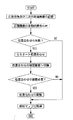
図3は、眼科画像処理装置1の制御動作を示すフローチャートである。以下、フローチャートを用いて、より具体的に眼科画像処理装置1の制御動作について説明する。
<Control action>
FIG. 3 is a flowchart showing the control operation of the ophthalmic image processing apparatus 1. Hereinafter, the control operation of the ophthalmic image processing apparatus 1 will be described more specifically with reference to flowcharts.
本実施形態においては、過去に、撮影装置Aによって、眼底撮影が行われ、その眼底正面像が取得されていた場合に、その後、他の装置にて眼底の経過観察をしていく場合を例として、説明していく。 In the present embodiment, in the past, when fundus photographing has been performed by the photographing apparatus A and the fundus front image has been acquired, the follow-up observation of the fundus is performed by another apparatus thereafter. I will explain.
<画像の取得>
初めに、撮影装置A及び撮影装置Bによって、正面画像及び三次元断層画像を含む画像データが取得され、画像処理装置10へ転送される。例えば、撮影装置Aによって、SLOを用いて撮影された被検眼の第1正面画像と、光干渉技術を用いて撮影された被検眼の三次元断層画像であって第1正面画像と関連付けられた第1の三次元断層画像と、を含む第1画像データが取得され、画像処理装置10へ転送される。また、撮影装置Bによって、OCT正面像撮像光学系を用いて撮影された被検眼の第2正面画像と、光干渉技術を用いて撮影された被検眼の三次元断層画像であって第2正面画像と関連付けられた第2の三次元断層画像と、を含む第2画像データが取得され、画像処理装置10へ転送される。画像処理装置10へ転送された各画像データは、メモリ72に記憶される。
<Acquisition of image>
First, image data including a front image and a three-dimensional tomographic image is acquired by the imaging device A and the imaging device B and transferred to the
<自動による位置合わせ>
次いで、画像処理装置10によって、自動的に正面画像間の位置合わせを行う。画像処理装置10の制御部70は、メモリ72に記憶されている画像データを用いて、撮影画像間の位置合わせ処理を行う。例えば、メモリ72に複数の画像データが記憶されている場合、検者は、操作部90を操作し、複数の画像データから経過観察を行う画像データを選択する。本実施例においては、上記記載の第1画像データと第2画像データが取得されたものとする。
<Automatic alignment>
Next, the
制御部70は、検者によって選択された画像データをメモリ72から呼び出し、位置合わせを行う。位置合わせには、画像データの正面画像が用いられる。制御部70は、検者によって選択された画像データの内、基準となる正面画像を設定し、基準正面画像に対する他の正面画像の位置ずれ量を検出する。なお、本実施例において、第1画像データと第2画像データの内、第1画像データの第1正面画像を基準正面画像とする。
The
制御部70は、第1正面画像(基準正面画像)と第2正面画像(他の正面画像)との位置ずれ量を検出し、基準正面画像に対して他の正面画像の位置合わせを行う。すなわち、基準正面画像と他の正面画像を比較して、基準正面画像に対する他の正面画像の位置ずれ方向及び位置ずれ量を画像処理により検出する。
The
ずれ量の検出方法としては、種々の画像処理手法(各種相関関数を用いる方法、フーリエ変換を利用する方法、特徴点のマッチングに基づく方法)を用いることが可能である。 Various image processing methods (a method using various correlation functions, a method using Fourier transform, and a method based on feature point matching) can be used as a method for detecting the shift amount.
例えば、基準正面画像又は他の正面画像を1画素ずつ位置ずれさせ、基準正面画像と他の正面画像を比較し、両データが最も一致したとき(相関が最も高くなるとき)の両データ間の位置ずれ方向及び位置ずれ量を検出する手法が考えられる。また、所定の基準正面画像及び他の正面画像から共通する特徴点を抽出し、抽出された特徴点の位置ずれ方向及び位置ずれ量を検出する手法が考えられる。 For example, the reference front image or another front image is shifted by one pixel, the reference front image and another front image are compared, and when both data are the best (when the correlation is the highest), A method for detecting the direction of displacement and the amount of displacement is conceivable. Further, a method of extracting a common feature point from a predetermined reference front image and another front image and detecting a position shift direction and a position shift amount of the extracted feature point is conceivable.
本実施例においては、基準正面画像に対する他の正面画像を1画素単位でずらしながら、相関値(値が大きいほど画像間の相関が高くなる(最大1))を逐次算出する。そして、制御部70は、相関値が最大となるときの画素の偏位量(ずらした画素数)を位置ずれ量とし、また、ずらした方向を位置ずれ方向として検出する。
In this embodiment, the correlation value (the larger the value, the higher the correlation between the images (maximum 1)) is sequentially calculated while shifting another front image with respect to the reference front image in units of one pixel. Then, the
制御部70は、検出した位置ずれ量及び位置ずれ方向に基づいて、基準正面画像と他の正面画像の位置合わせを行う。正面画像間の位置合わせ終了後、制御部70は、正面画像間の比較を行い、解析マップの取得を行う。
The
例えば、制御部70は、撮影装置Aと撮影装置Bによって取得された三次元断層画像を解析し、眼底上における層厚を二次元的に示す層厚マップをそれぞれ作成する(詳細は後述する)。このとき、各装置の三次元断層画像と正面画像は、マッチングされているため、正面画像と層厚マップとの関連付けが可能である。これにより、各撮影装置によって取得された層厚マップの位置合わせを行うことができる。制御部70は、撮影装置Aと撮影装置Bにて取得した正面画像において共通の領域において、層厚マップ間の差分結果を示す解析マップ(差分マップ)を作成する。
For example, the
ここで、正面画像間の撮影位置が極端に異なる場合や正面画像の画質が悪い場合には、位置合わせの精度が悪くなることや位置合わせに失敗することがある。そして、正面画像の比較を行った場合に、解析マップが取得できない場合や異常な結果の解析マップを取得してしまう場合がある。 Here, when the shooting positions between the front images are extremely different or when the image quality of the front images is poor, the alignment accuracy may be deteriorated or the alignment may fail. When comparing front images, there are cases where an analysis map cannot be acquired or an analysis map with an abnormal result is acquired.
<セミオート位置合わせ>
以下、上記の自動位置合わせが失敗した場合の位置合わせ処理について説明する。例えば、検者は、取得した解析マップを観察し、解析マップを取得できなかった場合や解析マップの結果が異常であった場合に操作部90を操作することによって、セミオート位置合わせモードにモード切換えを行う。もちろん、制御部70によってモード切換に関する制御動作が行われてもよい。例えば、制御部70は、解析マップが取得できなかった場合又は解析マップが異常な結果を示した場合に、セミオート位置合わせモードにモード切換を行う。また、制御部70は、モード切換を行った方がよい旨をモニタ75上に表示してもよい。
<Semi-auto alignment>
Hereinafter, the alignment process when the automatic alignment fails will be described. For example, the examiner observes the acquired analysis map and switches the mode to the semi-auto alignment mode by operating the
以下、セミオート位置合わせについて説明する。セミオート位置合わせモードにモード切換が行われると、制御部70は、セミオートによって位置合わせを行うためのセミオート位置合わせ画面を表示させる。図4は、モニタ75上に表示されるセミオート位置合わせ画面の一例を示す図である。
Hereinafter, semi-automatic alignment will be described. When the mode is switched to the semi-auto alignment mode, the
モニタ75には、第1正面画像(基準正面画像)20、第2正面画像(他の正面画像)30、ポインタ60が表示される。制御部70は、操作部90の操作信号に基づいて、モニタ75上でポインタ60を移動させる。ポインタ60は、例えば、十字マークやペンマーク等で表示される。
On the
初めに、検者は、操作部90を操作して、基準正面画像20上でポインタ60を移動させ、眼底部位の特徴点(特徴的な部分)を指定する。特徴点としては、血管数が多い部位や血管の分岐地点等が好ましい。検者によって、特徴点が指定されると、制御部70は、特徴点を位置合わせの基準点aして設定する。そして、制御部70は、基準点aに対応する対応点a'を他の正面画像上から探索する。
First, the examiner operates the
制御部70は、対応点a'を探索するために、基準正面画像20上に対応点a'を探索するためのテンプレート画像Tを設定する。テンプレート画像Tは、基準点aの位置座標に基づいて、基準点aを中心に所定領域が抽出されることによって設定される。所定領域としては、例えば、予め、画像サイズの5%等に設定される。そして、例えば、制御部70は、他の正面画像上で、設定されたテンプレート画像を1画素単位でずらしながら、相関値(値が大きいほど画像間の相関が高くなる(最大1))を探索する。そして、制御部70は、相関値が最大となるときの位置を判定し、判定結果から対応点a'を設定する。なお、基準点aの位置座標に基づいて、他の正面画像上においても、所定の探索領域を設定し、設定した探索領域内でテンプレート画像の相関値を検出し、対応点a'の設定を行ってもよい。
The
なお、設定された対応点a'を変更することも可能である。検者は、操作部90を操作し、ポインタ60を他の正面画像上に移動させ、ポインタ60を設定された対応点a'の位置合わせる。そして、検者は、対応点a'の位置でドラックし、移動させることによって、対応点a'を移動させ、調整を対応点a'の位置を調整することができる。
It is also possible to change the set corresponding point a ′. The examiner operates the
以上にようにして、基準点a及び対応点a'が設定される。検者は、同様にして、複数の基準点を指定する。本実施例においては、3つの基準点が指定されたものとする。基準点及び対応点が設定されると、制御部70は、各基準点の位置座標と各対応点の位置座標に基づいて、各基準点と各対応点が一致又は誤差が最小となるように、他の正面画像30のアフィン変換(平行移動、回転移動、相対倍率変更)が行われる。もちろん、アフィン変換の内いずれかの移動又は変換のみが行われる構成としてもよい。これによって、正面画像間の位置合わせを行うことができる。
As described above, the reference point a and the corresponding point a ′ are set. The examiner similarly designates a plurality of reference points. In this embodiment, it is assumed that three reference points are designated. When the reference point and the corresponding point are set, the
なお、位置合わせを開始する設定を設けてもよい。例えば、基準点が所定数設定された場合に、制御部70が位置合わせを開始するようにする。所定数は、例えば、変換処理を行うための、情報が算出できる数にて設定される。本実施例の場合、少なくとも3つ以上の基準点を設定して、位置合わせ処理を行う。
A setting for starting the alignment may be provided. For example, when a predetermined number of reference points are set, the
以上のように、セミオート位置合わせによって、特徴量の大きな部位を選択して指定できるため、対応点を設定する際に、誤った対応点を設定する可能性を減少させることができる。また、容易に、基準点として設定された位置と同一の位置を対応点として設定することができ、検者による対応点の選択失敗や検者の手間を省くことができる。このため、容易に精度良く画像間の位置合わせを行うことができる。
<位置合わせ結果の確認>
なお、本実施例において、位置合わせが精度良く行われたか否かを確認する位置合わせ確認モードがある。検者は、操作部90を操作することによって、位置合わせ確認モードにモード切換えを行う。
As described above, since a part having a large feature amount can be selected and specified by semi-automatic alignment, the possibility of setting an incorrect corresponding point when setting corresponding points can be reduced. Further, the same position as the position set as the reference point can be easily set as the corresponding point, and it is possible to save the operator from failing to select the corresponding point and the trouble of the examiner. For this reason, alignment between images can be easily performed with high accuracy.
<Confirmation of alignment result>
In this embodiment, there is an alignment confirmation mode for confirming whether or not the alignment is performed with high accuracy. The examiner switches the mode to the alignment confirmation mode by operating the
以下、位置合わせ確認モードについて説明する。位置合わせ確認モードにモード切換が行われると、制御部70は、位置合わせが精度良く行われたか否かを確認するための位置合わせ確認画面を表示させる。図5は、モニタ75上に表示される位置合わせ確認画面の一例を示す図である。
Hereinafter, the alignment confirmation mode will be described. When the mode is switched to the alignment confirmation mode, the
モニタ75には、基準正面画像20、他の正面画像30、ポインタ60、合成正面画像25が表示される。基準正面画像20と他の正面画像30上には、位置合わせの基準として用いられた基準点a1〜a3と対応点a'1〜a'3が表示される。合成正面画像25は、基準正面画像20と他の正面画像30から少なくとも一部の画像データを抽出し、合成処理し作成された画像である。
On the
以下、合成正面画像の作成について説明する。制御部70は、位置合わせが行われた基準正面画像の静止画データと他の正面画像の静止画データが交互に繰り返して配置されるように、基準正面画像と他の正面画像を合成処理する。例えば、交互に繰り返す配置のパターンとしては、基準正面画像20と他の正面画像30が格子状の領域で抽出され、交互に配置されたチェック柄パターンの表示形式がある。
Hereinafter, creation of a composite front image will be described. The
図6は、チェック柄パターンの表示形式である合成正面画像を作成する際の画像データの配置について説明する図である。図6に示されるように、例えば、制御部70は、画像間の位置合わせが完了した正面画像F1と正面画像F2が合成処理され、チェック柄パターンの表示形式である合成正面画像Cを作成する。制御部70は、正面画像F1の静止画データから一部の画像データを抽出し、配置する。また、制御部70は、正面画像F2の静止画データから一部の画像データを抽出し、配置する。このとき、正面画像F1と正面画像F2から抽出される画像データに重複する部分がないように画像データを抽出する。例えば、図6に示されるように、合成正面画像Cを構成する画像データは、正面画像F1の画像データ(斜線部)と正面画像F2の画像データ(白紙部)がチェック柄パターンの表示形式上に交互に並べて配置される。以上のようにして、合成正面画像が作成される。
合成正面画像は、2つの画像データが交互に配置されているため、各正面画像間の位置合わせにずれが生じている場合には、隣り合う画像間で血管の走行位置等がずれて表示される。このため、検者は、合成正面画像25内の隣り合う画像を比較して、血管等の走行状態のずれを観察することによって、合成正面画像25から血位置合わせを行った正面画像間のずれを確認することができる。
FIG. 6 is a diagram illustrating the arrangement of image data when creating a composite front image that is a display format of a check pattern. As illustrated in FIG. 6, for example, the
In the synthesized front image, two image data are alternately arranged. If there is a misalignment between the front images, the running position of the blood vessel is shifted between adjacent images. The For this reason, the examiner compares adjacent images in the synthesized
なお、画像間のずれを定量的に表示するようにしてもよい。制御部70は、合成正面画像より画像類似度情報を取得し、モニタ75上に表示する。例えば、画像類似度情報は、正規化相互相関や相互情報量等が挙げられる。このようにすることによって、検者は、合成正面画像の目視による観察と定量的な判断を行うことができるため、正面画像間のずれの把握を行いやすくなる。
In addition, you may make it display the shift | offset | difference between images quantitatively. The
なお、画像データの配置位置においては、変更が可能である。検者は、操作部90を操作し、スライダーバー35を移動させることによって、チェック柄パターンの表示状態を変更できる。例えば、検者によって、スライダーバー35が左右方向に移動されるに伴って、チェック柄パターンが反転する。この場合、正面画像F1と正面画像F2の画像データの配置位置が逆となる。
Note that the arrangement position of the image data can be changed. The examiner can change the display state of the check pattern by operating the
なお、画像データを配置した場合には、位置合わせや画像サイズによっては、画像が表示されない部位(スペース)が生じる。この場合、表示されない状態を維持してもよいし、スペースに画像データが補間されるように、相対倍率を変更して、画像データのサイズを調整してもよい。 When image data is arranged, a part (space) where an image is not displayed is generated depending on the alignment and the image size. In this case, the non-displayed state may be maintained, or the size of the image data may be adjusted by changing the relative magnification so that the image data is interpolated in the space.
以下、位置合わせ確認画面上における制御動作について説明する。位置合わせ確認モードにモード切換が行われると、制御部70は、位置合わせに用いた各正面画像から合成正面画像25を作成し、モニタ75上に表示させる。検者は、作成された合成正面画像25を観察し、位置合わせ結果を確認する。このとき、位置合わせ結果が好ましくない場合には、基準正面画像20、他の正面画像30、合成正面画像25のいずれかの画像上でポインタ60を操作して、位置合わせの調整を行う。
Hereinafter, the control operation on the alignment confirmation screen will be described. When the mode is switched to the alignment confirmation mode, the
例えば、検者が操作部90を操作し、他の正面画像30中の対応点a'1を移動させることによって、制御部70に操作信号が入力される。制御部70は、モニタ75に表示信号を出力することによって、対応点a'1の位置を変更させる。制御部70は、対応点a'1の位置を移動させるとともに、モニタ75に表示されている合成正面画像25上において、他の正面画像30から抽出した画像データに対応する部分の画像を変更する。
For example, when the examiner operates the
他の正面画像30から抽出した画像データに対応する部分の画像を変更について、より具体的に説明する。制御部70は、移動後の対応点a'1と基準点a1との位置座標の関係から、位置合わせをやり直す。すなわち、対応点が変更されると、制御部70は、各基準点の位置座標と各対応点(変更された対応点とその他の対応点)の位置座標に基づいて、他の正面画像のアフィン変換を行い、静止画データをメモリ72に記憶させる。そして、制御部70は、新たに位置合わせ行った後の他の正面画像と基準正面画像とによって、新たな合成正面画像25を作成し、モニタ75上に表示する。これによって、対応点を変更することによって、合成正面画像25中における他の正面画像部分の画像データが変更される。
The change of the image corresponding to the image data extracted from the other
なお、上記説明においては、対応点の変更によって、合成正面画像の変更を行う構成としたがこれに限定されない。例えば、基準点を変更してもよい。基準点を変更した場合、基準点と対応点の位置情報に基づいて、他の正面画像がアフィン変換され、合成正面画像上での他の正面画像の部分が変更される。もちろん、基準正面画像がアフィン変換される構成としてもよい。また、合成正面画像中の領域をドラックし、移動させることによって、他の正面画像又は基準正面画像を移動させる構成としてもよい。 In the above description, the composite front image is changed by changing the corresponding points. However, the present invention is not limited to this. For example, the reference point may be changed. When the reference point is changed, the other front image is affine transformed based on the position information of the reference point and the corresponding point, and the part of the other front image on the composite front image is changed. Of course, the reference front image may be affine transformed. In addition, another front image or the reference front image may be moved by dragging and moving a region in the composite front image.
検者は、合成正面画像を観察しながら、対応点を移動させ、合成正面画像中の画像が一致するように、位置合わせの調整をする。例えば、検者は、合成正面画像中の血管部分等のずれが少なくなるように位置合わせを行う。 The examiner moves the corresponding point while observing the synthesized front image, and adjusts the alignment so that the images in the synthesized front image match. For example, the examiner performs alignment so that the deviation of the blood vessel portion or the like in the composite front image is reduced.
以上のように、位置合わせ確認モードによって、位置合わせの確認及び調整を行うことによって、精度良く位置合わせを行うことができる。また、合成正面画像によって、血管等のずれから正面画像間のずれが容易に観察であるため、精度良く位置合わせを行うことができる。
<位置合わせ終了後>
正面画像間の位置合わせ終了後、制御部70は、正面画像間の比較を行い、解析マップの取得を行う。制御部70は、撮影装置Aと撮影装置Bによって取得された三次元断層画像を解析し、眼底上における層厚を二次元的に示す層厚マップをそれぞれ作成する。なお、本実施形態において、位置合わせ終了後に、解析マップを作成する構成としたがこれに限定されない。位置合わせ中に解析マップを作成するようにしてもよい。
As described above, alignment can be performed with high accuracy by performing alignment confirmation and adjustment in the alignment confirmation mode. In addition, since the shift between the front images can be easily observed from the shift of the blood vessel or the like by the synthesized front image, alignment can be performed with high accuracy.
<After completion of alignment>
After the alignment between the front images is completed, the
以下、層厚マップの作成について説明する。制御部70は、取得された眼底正面画像における眼底の層情報を画像処理により検出する。そして、検出結果は、メモリ72に画像データと共に記憶される。
Hereinafter, creation of the layer thickness map will be described. The
層を検出する場合、例えば、三次元断層画像の画像データ中のXY平面における断層画像が用いられる。そして、断層画像の輝度レベルが検出され、所定の網膜層(例えば、網膜表面と網膜色素上皮層)に相当する層境界が画像処理により抽出される。そして、層境界の間隔が計測されることにより、層厚が計測される。 When detecting a layer, for example, a tomographic image on the XY plane in the image data of a three-dimensional tomographic image is used. Then, the luminance level of the tomographic image is detected, and a layer boundary corresponding to a predetermined retinal layer (for example, the retinal surface and the retinal pigment epithelium layer) is extracted by image processing. Then, the layer thickness is measured by measuring the interval between the layer boundaries.
そして、制御部70は、各断層画像に関して網膜各層(例えば、網膜表層、網膜色素上皮層)の厚みを算出する。本実施例において、制御部70は、取得された解析結果に基づいて、各断層像の解析結果をグラフィックにて示す層厚マップを作成する。層厚マップは、例えば、眼底の層厚に関する二次元分布データを示す。制御部70は、層厚マップを作成した後、メモリ72に層厚マップを記憶させる。制御部70は、各正面画像の層厚マップを作成する。
Then, the
以上のようにして、層厚マップが作成されると、制御部70は、層厚マップ間の比較結果を示す差分マップを作成する。もちろん、制御部70は、差分マップを作成することなく、各装置における層厚マップのデータをモニタ75に送信し、表示してもよい。
As described above, when the layer thickness map is created, the
ここで、各装置の三次元断層画像と正面画像は、マッチングされているため、正面画像と層厚マップとの関連付けが可能である。これにより、各撮影装置によって取得された正面画像の位置合わせを行うことで、層厚マップの位置合わせを行うことができる。制御部70は、撮影装置Aと撮影装置Bにて取得した正面画像において共通の領域において、層厚マップ間の差分結果を示す差分マップを作成する。
Here, since the three-dimensional tomographic image and the front image of each device are matched, the front image and the layer thickness map can be associated with each other. Thereby, alignment of the layer thickness map can be performed by performing alignment of the front image acquired by each imaging device. The
以上のように、撮影装置Aと撮影装置Bで、眼底正面画像の取得手段が異なった場合においても、眼底正面像の差分マップを取得することができ、撮影装置間での観察を行うことができる。これによって、前回の観察から複数年経過しており、装置の仕様や測定原理が大きく変更されている場合があっても、眼底の変化を検出することが可能となり、経過観察を行うことができる。 As described above, even when the imaging device A and the imaging device B have different fundus front image acquisition means, a difference map of the fundus front image can be acquired, and observation between the imaging devices can be performed. it can. This makes it possible to detect changes in the fundus and perform follow-up observations even if there are cases where multiple years have passed since the previous observation and the specifications and measurement principles of the device have changed significantly. .
なお、上記のようにして正面画像として利用されたデータは、異なる撮影装置間における走査位置の調整に用いるようにしてもよい。例えば、撮影装置Bは、撮影装置Aで取得されたSLO画像と、三次元断層画像に対応する走査位置情報をメモリ(データベース)から取得する。そして、撮影装置Bによって取得されるOCT正面像とSLO画像との位置ずれを画像処理により検出する。そして、メモリから取得された走査位置情報を,検出された位置ずれによって補正するように光スキャナを制御することにより、同一部位に対する位置合わせを行う。 Note that the data used as the front image as described above may be used for adjustment of the scanning position between different photographing apparatuses. For example, the imaging apparatus B acquires the SLO image acquired by the imaging apparatus A and the scanning position information corresponding to the three-dimensional tomographic image from the memory (database). Then, a positional shift between the OCT front image acquired by the imaging apparatus B and the SLO image is detected by image processing. Then, the optical scanner is controlled so as to correct the scanning position information acquired from the memory based on the detected positional deviation, thereby aligning the same part.
なお、本実施形態においては、眼科画像処理装置1について、断層像の取得手段においては、各装置とも共通の手段にて取得おり、眼底正面画像の取得手段においては、それぞれ異なった手段にて取得を行っている撮影装置を用いて説明したが、これに限定されない。画像の種類が共通のものを取得する装置であれば適用可能である。例えば、本実施形態で用いたスペクトルメータを用いたスペクトルドメインOCT間だけでの適用でなく、波長可変光源を備えるSwept-source OCT(SS−OCT)やTime-domain OCT(TD−OCT)であってもよい。 In the present embodiment, for the ophthalmologic image processing apparatus 1, the tomographic image acquisition means is acquired by means common to the respective apparatuses, and the fundus front image acquisition means is acquired by different means. However, the present invention is not limited to this. The present invention is applicable to any device that acquires a common image type. For example, it is not only applied between spectral domain OCTs using the spectrum meter used in the present embodiment, but also Swept-source OCT (SS-OCT) or Time-domain OCT (TD-OCT) including a wavelength tunable light source. May be.
この場合、例えば、各三次元断層画像を形成する単位ピクセル当たりの実寸法データ(深さ方向及び横方向)を用いて、第1三次元断層画像と第2三次元断層画像の実寸が同じ大きさになるように、深さ方向に関して倍率が調整されると共に、深さ方向に垂直なXY二次元方向に関して倍率が調整される。 In this case, for example, the actual size of the first 3D tomographic image and the second 3D tomographic image are the same size using the actual size data (depth direction and lateral direction) per unit pixel forming each 3D tomographic image. Thus, the magnification is adjusted in the depth direction, and the magnification is adjusted in the XY two-dimensional direction perpendicular to the depth direction.
なお、本実施形態においては、眼底正面画像及び眼底断層画像を撮像する眼底撮影装置を例として挙げたがこれに限定されない。例えば、前眼部正面画像及び前眼部断層画像を撮像する前眼部撮影装置においても、本発明は適用可能である。この場合、SLOは、被検眼前眼部上でレーザ光を走査し、前眼部からの反射光を共焦点開口を介して受光して前眼部正面画像を得る。また、OCT正面像撮像光学系では、被検眼前眼部上でOCT測定光を走査し、前眼部からの反射光と参照光とが合成された光を受光して前眼部正面画像を得る。また、眼底カメラ光学系では、被検眼前眼部に対して照明光を一体的に照射し、前眼部からの反射光を二次元撮像素子で受光して前眼部正面画像を得る。 In the present embodiment, a fundus imaging apparatus that captures a fundus front image and a fundus tomographic image has been described as an example, but the present invention is not limited thereto. For example, the present invention can also be applied to an anterior segment imaging device that captures an anterior segment front image and an anterior segment tomographic image. In this case, the SLO scans the laser light on the anterior eye portion of the eye to be examined, and receives the reflected light from the anterior eye portion through the confocal aperture to obtain an anterior eye portion front image. Further, in the OCT front image capturing optical system, the OCT measurement light is scanned on the anterior eye portion of the eye to be examined, and the light obtained by combining the reflected light from the anterior eye portion and the reference light is received to obtain the front image of the anterior eye portion. obtain. Further, in the fundus camera optical system, illumination light is integrally irradiated to the anterior ocular segment to be examined, and reflected light from the anterior ocular segment is received by a two-dimensional image sensor to obtain an anterior ocular segment front image.
なお、本発明においては、本実施形態に記載した装置に限定されない。例えば、上記実施形態の機能を行う眼科画像処理ソフトウェア(プログラム)をネットワークや各種記憶媒体を介して、システムあるいは装置に供給する。そして、システムあるいは装置のコンピュータ(例えば、CPU等)がプログラムを読み出し、実行することも可能である。 Note that the present invention is not limited to the apparatus described in this embodiment. For example, ophthalmic image processing software (program) that performs the functions of the above embodiments is supplied to a system or apparatus via a network or various storage media. A computer of the system or apparatus (for example, a CPU) can also read and execute the program.
1 眼科画像処理装置
10 画像処理装置
25 合成正面画像
70 制御部
72 記憶部(メモリ)
75 モニタ
90 操作入力部
DESCRIPTION OF SYMBOLS 1 Ophthalmic
75
Claims (4)
該基準正面画像上の特徴部分を操作入力部から入力される操作信号に基づいて選択可能とすると共に、該基準正面画像において選択された特徴部分に対応する特徴部分を該他の正面画像において画像処理により探索し、該基準正面画像における特徴部分と、該他の正面画像において探索された特徴部分に基づいて、該基準正面画像と該他の正面画像とのマッチング処理を画像処理により行う画像処理部を有し、眼科撮影装置によって取得された異なる画像データ間の位置合わせを行う眼科画像処理装置であって、
前記基準正面画像は、光干渉断層計によって取得された第1の三次元断層画像に対応付けされた正面画像であって、
前記他の正面画像は、光干渉断層計によって取得され第1の三次元断層画像とは異なるタイミングで取得された第2の三次元断層画像に対応付けされた正面画像であって、
前記画像処理部は、
前記基準正面画像と前記他の正面画像とのマッチング結果に基づいて、前記第1の三次元断層画像の解析結果を示す第1のマップと、前記第2の三次元断層画像の解析結果を示す第2のマップとの位置合わせを行うことを特徴とする眼科画像処理装置。 The image data of the reference front image acquired by the ophthalmologic photographing apparatus and the image data of another front image acquired at a timing different from the reference front image are acquired from the storage unit and displayed on the monitor.
A feature portion on the reference front image can be selected based on an operation signal input from the operation input unit , and a feature portion corresponding to the feature portion selected in the reference front image is imaged in the other front image. Image processing for searching by processing and performing matching processing between the reference front image and the other front image by image processing based on the feature portion in the reference front image and the feature portion searched in the other front image It has a section, an ophthalmologic image processing apparatus that performs positioning between the different image data obtained by the ophthalmic photographing apparatus,
The reference front image is a front image associated with a first three-dimensional tomographic image acquired by an optical coherence tomography,
The other front image is a front image associated with a second three-dimensional tomographic image acquired by an optical coherence tomography and acquired at a different timing from the first three-dimensional tomographic image,
The image processing unit
Based on the matching result between the reference front image and the other front image, the first map showing the analysis result of the first three-dimensional tomographic image and the analysis result of the second three-dimensional tomographic image are shown. An ophthalmologic image processing apparatus characterized by performing alignment with a second map .
前記第1のマップは、前記第1の三次元断層画像の層厚解析結果を示す第1の層厚マップであって、The first map is a first layer thickness map showing a layer thickness analysis result of the first three-dimensional tomographic image,
前記第2のマップは、前記第2の三次元断層画像の層厚解析結果を示す第2の層厚マップであって、The second map is a second layer thickness map showing a layer thickness analysis result of the second three-dimensional tomographic image,
前記画像処理部は、The image processing unit
前記第1のマップと前記第2のマップとの間の比較結果を示す差分マップを作成することを特徴とする眼科画像処理装置。An ophthalmologic image processing apparatus that creates a difference map indicating a comparison result between the first map and the second map.
前記他の正面画像は、前記基準正面画像を取得した眼科撮影装置とは異なる眼科撮影装置によって取得される眼科画像処理装置。The other front image is an ophthalmologic image processing apparatus acquired by an ophthalmologic imaging apparatus different from the ophthalmologic imaging apparatus that acquired the reference front image.
眼科撮影装置によって取得された基準正面画像の画像データと,該基準正面画像と異なるタイミングで取得された他の正面画像の画像データと,を記憶部から取得する工程と、
前記基準正面画像上の特徴部分を操作入力部から入力される操作信号に基づいて、選択可能とする工程と、
前記基準正面画像において選択された特徴部分に対応する特徴部分を前記他の正面画像において画像処理により探索する工程と、
前記基準正面画像における特徴部分と、前記他の正面画像において探索された特徴部分とに基づいて、該基準正面画像と該他の正面画像とのマッチング処理を画像処理により行う画像処理工程と、
をコンピュータに実行させる眼科画像処理プログラムであって、
前記基準正面画像は、光干渉断層計によって取得された第1の三次元断層画像に対応付けされた正面画像であって、
前記他の正面画像は、光干渉断層計によって取得され第1の三次元断層画像とは異なるタイミングで取得された第2の三次元断層画像に対応付けされた正面画像であって、
前記画像処理工程は、
前記基準正面画像と前記他の正面画像とのマッチング結果に基づいて、前記第1の三次元断層画像の解析結果を示す第1のマップと、前記第2の三次元断層画像の解析結果を示す第2のマップとの位置合わせを行うことを特徴とする眼科画像処理プログラム。 In an ophthalmic image processing apparatus program for performing alignment between different image data acquired by an ophthalmic imaging apparatus,
Acquiring from the storage unit image data of the reference front image acquired by the ophthalmologic photographing apparatus and image data of another front image acquired at a different timing from the reference front image;
A step of selecting a feature portion on the reference front image based on an operation signal input from an operation input unit;
Searching for a feature portion corresponding to the feature portion selected in the reference front image by image processing in the other front image;
An image processing step of performing matching processing between the reference front image and the other front image by image processing based on the feature portion in the reference front image and the feature portion searched in the other front image;
An ophthalmologic image processing program causing a computer to execute the,
The reference front image is a front image associated with a first three-dimensional tomographic image acquired by an optical coherence tomography,
The other front image is a front image associated with a second three-dimensional tomographic image acquired by an optical coherence tomography and acquired at a different timing from the first three-dimensional tomographic image,
The image processing step includes
Based on the matching result between the reference front image and the other front image, the first map showing the analysis result of the first three-dimensional tomographic image and the analysis result of the second three-dimensional tomographic image are shown. An ophthalmologic image processing program characterized by performing alignment with a second map .
Priority Applications (1)
| Application Number | Priority Date | Filing Date | Title |
|---|---|---|---|
| JP2012019307A JP5998493B2 (en) | 2012-01-31 | 2012-01-31 | Ophthalmic image processing apparatus and program |
Applications Claiming Priority (1)
| Application Number | Priority Date | Filing Date | Title |
|---|---|---|---|
| JP2012019307A JP5998493B2 (en) | 2012-01-31 | 2012-01-31 | Ophthalmic image processing apparatus and program |
Publications (3)
| Publication Number | Publication Date |
|---|---|
| JP2013154120A JP2013154120A (en) | 2013-08-15 |
| JP2013154120A5 JP2013154120A5 (en) | 2015-03-12 |
| JP5998493B2 true JP5998493B2 (en) | 2016-09-28 |
Family
ID=49049909
Family Applications (1)
| Application Number | Title | Priority Date | Filing Date |
|---|---|---|---|
| JP2012019307A Active JP5998493B2 (en) | 2012-01-31 | 2012-01-31 | Ophthalmic image processing apparatus and program |
Country Status (1)
| Country | Link |
|---|---|
| JP (1) | JP5998493B2 (en) |
Families Citing this family (7)
| Publication number | Priority date | Publication date | Assignee | Title |
|---|---|---|---|---|
| JP2017104309A (en) * | 2015-12-10 | 2017-06-15 | 株式会社トプコン | Ophthalmologic image displaying device and ophthalmologic imaging device |
| US10679343B2 (en) | 2016-03-03 | 2020-06-09 | Nidek Co., Ltd. | Ophthalmic image processing apparatus and ophthalmic image processing program |
| JP7024240B2 (en) * | 2017-07-27 | 2022-02-24 | 株式会社ニデック | Ophthalmic system and ophthalmic system control program |
| CN108803008B (en) * | 2017-10-31 | 2021-01-05 | 成都理想境界科技有限公司 | Displacement amplification mechanism, optical fiber scanning device and projector |
| DE102018107622A1 (en) * | 2018-03-29 | 2019-10-02 | Imedos Systems GmbH | Apparatus and method for determining retinal blood pressure values and mapping retinal blood pressure values and perfusion pressure values |
| JP2020058647A (en) * | 2018-10-11 | 2020-04-16 | 株式会社ニコン | Image processing method, image processing device and image processing program |
| US11419495B2 (en) | 2019-10-30 | 2022-08-23 | Nikon Corporation | Image processing method, image processing device, and storage medium |
Family Cites Families (4)
| Publication number | Priority date | Publication date | Assignee | Title |
|---|---|---|---|---|
| JPH04336677A (en) * | 1991-05-14 | 1992-11-24 | Canon Inc | Picture processing method and system using the same |
| JP5349210B2 (en) * | 2009-08-31 | 2013-11-20 | 株式会社ニデック | Fundus image processing device |
| JP5570195B2 (en) * | 2009-12-07 | 2014-08-13 | 株式会社ニデック | OCT equipment |
| JP5564346B2 (en) * | 2010-07-08 | 2014-07-30 | 株式会社キーエンス | Magnifying observation device |
-
2012
- 2012-01-31 JP JP2012019307A patent/JP5998493B2/en active Active
Also Published As
| Publication number | Publication date |
|---|---|
| JP2013154120A (en) | 2013-08-15 |
Similar Documents
| Publication | Publication Date | Title |
|---|---|---|
| JP6115007B2 (en) | Ophthalmic image processing apparatus and program | |
| US9687148B2 (en) | Photographing apparatus and photographing method | |
| JP5998493B2 (en) | Ophthalmic image processing apparatus and program | |
| JP5975126B2 (en) | Fundus observation apparatus and fundus observation program | |
| JP5735790B2 (en) | Ophthalmic imaging equipment | |
| JP6217185B2 (en) | Ophthalmic photographing apparatus and ophthalmic image processing program | |
| EP2633804B1 (en) | Ophthalmologic photographing apparatus | |
| JP6115073B2 (en) | Ophthalmic photographing apparatus and ophthalmic photographing program | |
| JP5601609B2 (en) | Ophthalmic observation program and ophthalmic observation apparatus | |
| EP2420181A1 (en) | Eyeground observation device | |
| JP5767014B2 (en) | Ophthalmic observation system and image processing method | |
| JP6184232B2 (en) | Image processing apparatus and image processing method | |
| JP6202924B2 (en) | Imaging apparatus and imaging method | |
| JP6572615B2 (en) | Fundus image processing apparatus and fundus image processing program | |
| JP6007517B2 (en) | Ophthalmic imaging equipment | |
| US9486134B2 (en) | Ophthalmologic imaging apparatus and ophthalmologic image processing apparatus | |
| JP2011224347A5 (en) | ||
| JP6213708B2 (en) | Ophthalmic photographing apparatus and ophthalmic photographing program | |
| JP6471593B2 (en) | OCT signal processing apparatus and OCT signal processing program | |
| JP6281177B2 (en) | Ophthalmic imaging equipment | |
| JP2013180127A (en) | Ophthalmologic photographing apparatus | |
| JP2013180126A (en) | Ophthalmologic photographing apparatus | |
| JP2019088382A (en) | Image processing device, ophthalmologic imaging device, image processing method, and program | |
| JP6606846B2 (en) | OCT signal processing apparatus and OCT signal processing program | |
| JP6260733B2 (en) | Ophthalmic photographing apparatus and ophthalmic photographing program |
Legal Events
| Date | Code | Title | Description |
|---|---|---|---|
| A521 | Request for written amendment filed |
Free format text: JAPANESE INTERMEDIATE CODE: A523 Effective date: 20150123 |
|
| A621 | Written request for application examination |
Free format text: JAPANESE INTERMEDIATE CODE: A621 Effective date: 20150123 |
|
| A977 | Report on retrieval |
Free format text: JAPANESE INTERMEDIATE CODE: A971007 Effective date: 20151130 |
|
| A131 | Notification of reasons for refusal |
Free format text: JAPANESE INTERMEDIATE CODE: A131 Effective date: 20151215 |
|
| A521 | Request for written amendment filed |
Free format text: JAPANESE INTERMEDIATE CODE: A523 Effective date: 20160215 |
|
| TRDD | Decision of grant or rejection written | ||
| A01 | Written decision to grant a patent or to grant a registration (utility model) |
Free format text: JAPANESE INTERMEDIATE CODE: A01 Effective date: 20160802 |
|
| A61 | First payment of annual fees (during grant procedure) |
Free format text: JAPANESE INTERMEDIATE CODE: A61 Effective date: 20160815 |
|
| R150 | Certificate of patent or registration of utility model |
Ref document number: 5998493 Country of ref document: JP Free format text: JAPANESE INTERMEDIATE CODE: R150 |
|
| R250 | Receipt of annual fees |
Free format text: JAPANESE INTERMEDIATE CODE: R250 |
|
| R250 | Receipt of annual fees |
Free format text: JAPANESE INTERMEDIATE CODE: R250 |
|
| R250 | Receipt of annual fees |
Free format text: JAPANESE INTERMEDIATE CODE: R250 |
|
| R250 | Receipt of annual fees |
Free format text: JAPANESE INTERMEDIATE CODE: R250 |
|
| R250 | Receipt of annual fees |
Free format text: JAPANESE INTERMEDIATE CODE: R250 |