〔遊技機の基本構成〕
本発明の一実施形態に係る遊技機について各図を参照して説明する。
[Basic configuration of gaming machine]
A gaming machine according to an embodiment of the present invention will be described with reference to the drawings.
以下、遊技機の基本的な構成について図面を参照して説明する。なお、以下の説明において、「上」、「下」、「左」、「右」、「表(前)」、「裏(後)」、「内」、及び、「外」は、特に断らない限り、遊技機1を遊技者側から見た場合における各方向を示すものとする。
Hereinafter, a basic configuration of the gaming machine will be described with reference to the drawings. In the following description, “upper”, “lower”, “left”, “right”, “front (front)”, “back (rear)”, “inside”, and “outer” are specifically excluded. Unless otherwise indicated, each direction when the gaming machine 1 is viewed from the player side is shown.
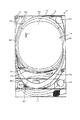
図1は、本実施形態の遊技機1の全体を示す模式図である。図2は、遊技機1に配される遊技盤70を示す模式図である。
FIG. 1 is a schematic diagram showing the entire gaming machine 1 of the present embodiment. FIG. 2 is a schematic diagram showing a game board 70 arranged in the gaming machine 1.
図1に示す遊技機1は、所謂パチンコ機である。この遊技機1には、遊技盤70が機内部に配置されている。遊技盤70上には、遊技球Pを射出する打球装置20がそのハンドル部分を前面に露出させて設けられている。ここで遊技盤70上とは遊技盤70の盤面上をいう。遊技機1は、遊技者が打球装置20のハンドルを操作することで遊技球Pを遊技盤70上に射出する。そして、遊技盤70上には、入賞口76等のポケットが配されており、遊技盤70上を転動流下する遊技球Pがこの入賞口76等に入球した場合に、所定数の遊技球Pを払い出す。遊技機1は、上皿30や下皿40を備えており、遊技球Pは、この上皿30や下皿40に払い出されて貯留される。
A gaming machine 1 shown in FIG. 1 is a so-called pachinko machine. In this gaming machine 1, a gaming board 70 is disposed inside the machine. On the game board 70, a ball hitting device 20 for injecting a game ball P is provided with its handle portion exposed to the front. Here, on the game board 70 refers to the board surface of the game board 70. The gaming machine 1 ejects the game ball P onto the game board 70 by the player operating the handle of the ball striking device 20. A pocket such as a winning opening 76 is arranged on the gaming board 70, and when a game ball P rolling down on the gaming board 70 enters the winning opening 76 or the like, a predetermined number of games are played. The ball P is paid out. The gaming machine 1 includes an upper plate 30 and a lower plate 40, and the game ball P is paid out and stored in the upper plate 30 and the lower plate 40.
このような遊技機1は、機体の外郭をなす縦長方形状の外枠10を備えている。外枠10は、遊技ホールの島設備に取り付け固定される。外枠10の下部は、合成樹脂製の腰板ユニット11で構成されている。外枠10の開口前面側には、各種の遊技用構成部材をセットするために縦長方形状の中枠12が開閉可能に取り付けられている。外枠10には、一方の側縁部にヒンジ機構13が設けられており、中枠12は、ヒンジ機構13に枢支されることで開閉可能となっている。
Such a gaming machine 1 includes a vertical rectangular outer frame 10 that forms an outline of the machine body. The outer frame 10 is attached and fixed to the island facility of the game hall. The lower part of the outer frame 10 is composed of a synthetic resin waist plate unit 11. A vertical rectangular middle frame 12 is attached to the front side of the outer frame 10 so as to be openable and closable in order to set various game components. The outer frame 10 is provided with a hinge mechanism 13 at one side edge, and the middle frame 12 can be opened and closed by being pivotally supported by the hinge mechanism 13.
中枠12の前面側には、機内部に配置された遊技盤70を透視保護するためのガラス枠を備えた前枠14と上皿30とが、横開き状態で開閉可能に組み付けられている。この前枠14と上皿30も外枠10に設けられたヒンジ機構13で枢支されることで開閉可能となっている。中枠12の前面側において上皿30の下方には、下皿40や打球装置20のハンドルが装着されている。
On the front side of the middle frame 12, a front frame 14 provided with a glass frame for protecting the game board 70 disposed inside the machine and a top plate 30 are assembled so as to be openable and closable in a laterally open state. . The front frame 14 and the upper plate 30 can also be opened and closed by being pivotally supported by a hinge mechanism 13 provided on the outer frame 10. On the front side of the middle frame 12, a lower plate 40 and a handle of the ball striking device 20 are mounted below the upper plate 30.
上皿30には、その左方側に機内部から払出される遊技球Pの上皿払出口31が設けられている。入賞等により払い出された遊技球Pは、上皿払出口31から上皿30に排出される。そして、上皿30に貯留されている遊技球Pは、機内へ取り込まれて、打球装置20によって遊技盤70に向けて発射される。上皿30の前面には、上皿球抜きボタン32が設けられている。上皿30と下皿40とは、図示しない球抜き通路で繋がっている。球抜き通路は、上皿球抜きボタン32の押下操作によって開通し、上皿30に貯留されている遊技球Pを下皿40に向けて流下させる。
The upper plate 30 is provided with an upper plate discharge outlet 31 of the game ball P to be paid out from the inside of the machine on the left side. The game balls P that are paid out due to winning or the like are discharged from the upper plate payout port 31 to the upper plate 30. Then, the game balls P stored in the upper plate 30 are taken into the machine and are launched toward the game board 70 by the hitting device 20. An upper dish ball removal button 32 is provided on the front surface of the upper dish 30. The upper plate 30 and the lower plate 40 are connected by a ball passage not shown. The ball removal passage is opened by pressing the upper plate ball removal button 32 and causes the game balls P stored in the upper plate 30 to flow down toward the lower plate 40.
遊技機1は、入賞、図柄変動、大当り状態、リーチ状態などの各種遊技の状態に応じた各種の演出を行う。遊技機1の前面側には、各種音声を出力して音声演出を行うスピーカ50が配置されている。スピーカ50は、前枠14や中枠12の裏面に装着されており、装着部位に対応する遊技機1の表面には図示しない放音孔が複数形成されている。各スピーカ50は、効果音等の各種音声を出力し、音声出力に基づく遊技演出を行う。また、前枠14のほぼ全周を囲むように装飾ランプ75(図2参照)が配置されている。各装飾ランプ75は、LEDランプ等の発光体を備え、遊技の状態に応じて点灯または消灯して、発光装飾に基づく遊技演出を行う。
The gaming machine 1 performs various effects according to the state of various games such as winning, symbol variation, big hit state, reach state and the like. On the front side of the gaming machine 1, a speaker 50 that outputs various sounds and produces sound effects is disposed. The speaker 50 is mounted on the back surface of the front frame 14 and the middle frame 12, and a plurality of sound emitting holes (not shown) are formed on the surface of the gaming machine 1 corresponding to the mounting site. Each speaker 50 outputs various sounds such as sound effects and performs a game effect based on the sound output. Further, a decorative lamp 75 (see FIG. 2) is arranged so as to surround almost the entire circumference of the front frame 14. Each decoration lamp 75 includes a light emitter such as an LED lamp, and is turned on or off according to the state of the game to perform a game effect based on the light emission decoration.
図2に示すように、遊技盤70の前面には、外レール71と内レール72が敷設されている。外レール71と内レール72は、パチンコ遊技の主体となるほぼ円形の遊技領域74を遊技盤70上に区画形成する。内レール72は、外レール71の内側に敷設されている。外レール71と内レール72とは、遊技盤70の左下方から左上方に向かって延設されており、打球装置20から射出された遊技球Pを遊技領域74に誘導する円弧状の誘導路73を形成している。
As shown in FIG. 2, an outer rail 71 and an inner rail 72 are laid on the front surface of the game board 70. The outer rail 71 and the inner rail 72 partition and form a substantially circular game area 74 that is the main body of the pachinko game. The inner rail 72 is laid inside the outer rail 71. The outer rail 71 and the inner rail 72 are extended from the lower left to the upper left of the game board 70, and arc-shaped guide paths that guide the game balls P ejected from the ball striking device 20 to the game area 74. 73 is formed.
遊技盤70の遊技領域74には、複数の入賞口76が配されている。これらの各入賞口76は、遊技盤70から前方向に直立し、上方に開口を有するポケット形状を有する。ポケット内部には、遊技球Pを検知するセンサが配されている。遊技機1は、入賞口76に遊技球Pが入球すると、センサがこの入球を検知したことを契機として所定球数の遊技球Pが上皿30に払い出される。遊技盤70の遊技領域74の最下部には、いずれの入賞口76にも入球せずにアウト球となった遊技球Pが入球するアウト球口77が配設されている。このアウト球口77は、アウト球を回収して内部へ送出し、機外排出を行うために設けられている。
In the game area 74 of the game board 70, a plurality of winning holes 76 are arranged. Each of these winning openings 76 has a pocket shape that stands upright from the game board 70 in the forward direction and has an opening upward. A sensor for detecting the game ball P is disposed inside the pocket. In the gaming machine 1, when the game ball P enters the winning opening 76, a predetermined number of game balls P are paid out to the upper plate 30 when the sensor detects this ball entry. At the lowermost part of the game area 74 of the game board 70, an out ball port 77 into which a game ball P that has become an out ball without entering any of the winning ports 76 is disposed. The out ball port 77 is provided to collect the out ball, send it out to the inside, and discharge it out of the machine.
遊技盤70の遊技領域74には、中央に開口を有した大型の枠体であるセンター役物100が装着されている。センター役物100には遊技球が転動し得るステージが設けられている。
In the game area 74 of the game board 70, a center accessory 100 which is a large frame having an opening at the center is mounted. The center accessory 100 is provided with a stage on which a game ball can roll.
遊技領域74内であってセンター役物100の下方には、始動口79が設けられている。この始動口79は、遊技盤70から前方向に直立し、上方に開口を有するポケット形状を有する。ポケット内部には、遊技球Pを検知するセンサが配されている。遊技機1は、始動口79に遊技球Pが入球すると、センサがこの入球を検知したことを契機として図柄変動ゲームを開始する。
A start port 79 is provided in the game area 74 and below the center accessory 100. The starting port 79 has a pocket shape that stands upright from the game board 70 in the forward direction and has an opening upward. A sensor for detecting the game ball P is disposed inside the pocket. When the game ball P enters the start port 79, the gaming machine 1 starts the symbol variation game triggered by the sensor detecting this ball entry.
センター役物100の開口には、図柄表示部78が配置されている。図柄表示部78には、複数種類の図柄を変動させて複数列の図柄からなる図柄組み合わせを導出する図柄変動ゲームなどの表示演出の画像が表示される。
A symbol display section 78 is disposed in the opening of the center accessory 100. In the symbol display section 78, an image of a display effect such as a symbol variation game for deriving a symbol combination composed of a plurality of columns of symbols by varying a plurality of types of symbols is displayed.
図柄変動ゲームにおいて図柄表示部78では、複数種類の飾り図柄(以下、「飾図」と示す)を複数列で変動させて各列に飾図が表示される。飾図は、図柄表示部78で行われる表示演出を多様化するために用いられる演出用の図柄である。
In the symbol change game, the symbol display unit 78 displays a decorative symbol in each column by changing a plurality of types of decorative symbols (hereinafter referred to as “decorative symbols”) in a plurality of columns. The decorative drawing is a design for effect used to diversify display effects performed in the design display unit 78.
図柄表示部78には、図柄変動ゲームで導出される3列の図柄毎に対応して、各列の図柄を停止表示させる3つの図柄表示位置HP1,HP2,HP3が定められている。停止表示では、図柄表示部78の各図柄表示位置HP1〜HP3において図柄の種類を遊技者が識別可能な状態で図柄が表示される。この停止表示には図柄が一時的に停止している一旦停止表示と、図柄が確定的に停止している確定停止表示とがある。
In the symbol display section 78, three symbol display positions HP1, HP2, and HP3 for stopping and displaying symbols in each column are defined corresponding to each of the three columns derived in the symbol variation game. In the stop display, the symbols are displayed in a state in which the player can identify the symbol type at each symbol display position HP1 to HP3 of the symbol display section 78. This stop display includes a temporary stop display in which the symbol is temporarily stopped and a fixed stop display in which the symbol is definitely stopped.
そして、図柄表示部78では、図柄変動ゲームが開始すると図柄が変動表示されるとともに、変動の停止によって各列の図柄表示位置HP1〜HP3に1つの図柄が一旦停止表示され、その後に図柄変動ゲームが終了すると各列の図柄表示位置HP1〜HP3に1つの図柄が確定停止表示される。変動表示では、図柄表示部78において図柄が予め定めた表示順序にしたがって変動しながら表示される。
Then, in the symbol display section 78, when the symbol variation game is started, the symbols are displayed in a variable manner, and one symbol is temporarily stopped and displayed at the symbol display positions HP1 to HP3 in each column due to the stop of the variation, and then the symbol variation game is displayed. When is finished, one symbol is displayed on the symbol display positions HP1 to HP3 in each column. In the variable display, the symbols are displayed in the symbol display section 78 while changing in accordance with a predetermined display order.
図柄変動ゲームでは、各列に[1]〜[8]の8種類の数字が飾図として表示可能とされている。そして、図柄表示部78で図柄変動ゲームが開始すると、各列の図柄は、予め定められた表示順序で図柄表示部78の上方から下方にスクロールさせながら変動表示されるようになっている。
In the symbol variation game, eight types of numbers [1] to [8] can be displayed as decorative drawings in each column. When the symbol variation game is started on the symbol display unit 78, the symbols in each column are variably displayed while scrolling downward from above the symbol display unit 78 in a predetermined display order.
図柄表示部78には、当該図柄表示部78に定められる3つの図柄表示位置HP1〜HP3を結んでなる組み合わせ有効ラインLが形成されている。なお、図2では、説明の便宜上、各図柄表示位置HP1〜HP3、及び有効ラインLを図示しているが、実機においては、これらの図柄表示位置HP1〜HP3、及び有効ラインLが目視可能な状態で表示されている必要はない。有効ラインLに停止表示された3つの図柄からなる図柄組み合わせが、大当りか否かを遊技者に認識させるための有効な図柄組み合わせとなる。
In the symbol display part 78, a combination effective line L formed by connecting the three symbol display positions HP1 to HP3 defined in the symbol display part 78 is formed. In FIG. 2, for convenience of explanation, the symbol display positions HP1 to HP3 and the effective line L are illustrated. However, in the actual machine, the symbol display positions HP1 to HP3 and the effective line L are visible. It does not have to be displayed in the state. The symbol combination consisting of the three symbols stopped and displayed on the effective line L is an effective symbol combination for allowing the player to recognize whether or not the game is a big hit.
図柄変動ゲームでは、有効ラインLに停止表示させる3列の飾図を同一の飾図として形成した図柄組み合わせを、内部抽選で大当りを決定した場合に図柄表示部78に確定停止表示させる飾図の大当り図柄としている。例えば、飾図による大当りの図柄組み合わせは、[111]や[777]などである。一方、有効ラインLに停止表示させる3列の飾図を同一の飾図とせずに形成した図柄組み合わせを、内部抽選ではずれを決定した場合に演出表示装置に確定停止表示させる飾図のはずれ図柄としている。3列の飾図が同一の飾図とならない場合には、3列の飾図の全てが異なる場合や、2列の飾図が同一で、かつ1列の飾図が異なる場合が含まれる。例えば、飾図のはずれ図柄組み合わせは、[123]、[115]、[767]や[889]などである。
In the symbol variation game, when the symbol combination in which the three rows of ornaments to be displayed on the active line L are formed as the same ornament is determined by the internal lottery, the symbol display unit 78 displays the symbols to be confirmed and stopped. It is a big hit design. For example, the jackpot symbol combination by the decorative drawing is [111], [777] or the like. On the other hand, if a combination of symbols formed without the same decorative drawing as the three rows of decorative drawings to be displayed on the active line L is not determined in the internal lottery, the decorative graphic is displayed on the effect display device when the deviation is determined. It is said. When the three rows of decorative drawings do not become the same, the case where all of the three rows of decorative drawings are different or the case where the two rows of decorative drawings are the same and the one row of decorative drawings are different is included. For example, there are [123], [115], [767], [889], etc.
始動口79の下方には、大入賞口80が配されている。大入賞口80は、開閉動作可能な開閉扉80aで閉じられている。開閉扉80aは、図柄変動ゲームで大当りが決定されると、予め定めた開放時間や開放回数で開動作し、遊技球Pの入球を許容する。そして、大入賞口80には、遊技球Pを検知するセンサが設けられており、遊技機1は、大入賞口80への入球を検知すると、所定球数の遊技球Pを払い出す。
Below the start opening 79, a big prize opening 80 is arranged. The special winning opening 80 is closed by an openable / closable door 80a. When the big hit is determined in the symbol variation game, the open / close door 80a opens at a predetermined opening time or number of times to allow the game ball P to enter. The big winning opening 80 is provided with a sensor for detecting the game ball P, and the gaming machine 1 pays out a predetermined number of gaming balls P when detecting a ball entering the big winning opening 80.
センター役物100は、遊技機1の前後方向に所定の厚みを有しており、遊技盤70の前面から少なくとも遊技球Pの直径以上の厚み分突出して取り付けられている。センター役物100の枠体は、枠体上部100a及び枠体下部100bを有する。枠体上部100aは、図柄表示部78の上方において遊技領域74を左右に横断している。枠体下部100bは、図柄表示部78の下方において遊技領域74を左右に横断している。センター役物100のステージ122を転動する遊技球が勢い余って、裏ユニット(後述する)側に飛び出さないように仕切壁としての役割を担う仕切板120が設けられている。仕切板120は、図柄表示部78の表示を妨げないように透光性を有している。
The center accessory 100 has a predetermined thickness in the front-rear direction of the gaming machine 1 and is attached so as to protrude from the front surface of the game board 70 by a thickness that is at least the diameter of the game ball P. The frame of the center accessory 100 has a frame upper part 100a and a frame lower part 100b. The upper frame body 100a crosses the game area 74 left and right above the symbol display section 78. The frame lower part 100b crosses the game area 74 to the left and right below the symbol display part 78. A partition plate 120 serving as a partition wall is provided so that a game ball rolling on the stage 122 of the center accessory 100 does not jump out to the back unit (described later) side. The partition plate 120 has translucency so as not to disturb the display of the symbol display section 78.
遊技盤70は裏ユニット(図示省略)を有している。なお、裏ユニットを含めて遊技盤70という場合がある。
The game board 70 has a back unit (not shown). In some cases, the game board 70 includes the back unit.
裏ユニットは遊技盤70の背面に配設されている。裏ユニットの背面に図柄表示部78が取り付けられている。裏ユニットには図柄表示部78に対応するように開口が設けられている。
The back unit is disposed on the back of the game board 70. A symbol display unit 78 is attached to the back of the back unit. An opening is provided in the back unit so as to correspond to the symbol display section 78.
裏ユニットは、それと遊技盤70との間にスペースが画成されるように略コ字状に形成されている。画成されたスペースには、図示省略した演出装置を設けるための設置スペースとして用いられる。ここで、演出装置の一例としては、可動体、それを駆動させる力を発生する駆動部、駆動部の力を可動体に伝える機構を含むものとする。遊技盤70は、遊技盤70を介して図柄表示部78及び可動体を視認することが可能なように、例えばアクリル樹脂材で形成され、その全体が透過性を有している。
The back unit is formed in a substantially U shape so that a space is defined between it and the game board 70. The defined space is used as an installation space for providing an effect device (not shown). Here, an example of the rendering device includes a movable body, a drive unit that generates a force for driving the movable body, and a mechanism that transmits the force of the drive unit to the movable body. The game board 70 is formed of, for example, an acrylic resin material so that the symbol display unit 78 and the movable body can be visually recognized through the game board 70, and the whole has transparency.
これらの隙間はその周囲に様々な部品を設ける必要性から、前後方向、左右方向、及び上下方向に制限を受けるため、演出装置は可能な限り小型であることが好ましい。そのためには、演出装置を構成する部品の数を削減すればよいが、演出装置には可動体による多彩な可動演出を実現することが求められるから、可動体の数を削減し難いので、可動体以外の構成部品の数を削減することとなる。
Since these gaps are limited in the front-rear direction, the left-right direction, and the up-down direction because various parts need to be provided around them, the rendering device is preferably as small as possible. To that end, the number of parts that make up the production device can be reduced. However, since the production device is required to realize a variety of movable productions using movable bodies, it is difficult to reduce the number of movable bodies. This will reduce the number of components other than the body.
〔演出装置の主構成〕
以上、遊技機1の基本的な構成について説明した。次に、演出装置200の主な構成について、各図を参照して説明する。
[Main structure of the production device]
The basic configuration of the gaming machine 1 has been described above. Next, the main configuration of the rendering device 200 will be described with reference to the drawings.
図3は遊技盤70(図2参照)における収納位置にある可動体300を斜め前から見たときの演出装置200の斜視図、図4は遊技盤70における目的位置(出現位置)にある可動体300を斜め前から見たときの斜視図である。可動体300は、図3に示す収納位置では設置スペースにその大部分が収まり、図4は可動体300が目的位置にあることを示す。その目的位置にある可動体は、センター役物100(図2参照)の開口内部にその一部が出現する。
FIG. 3 is a perspective view of the rendering device 200 when the movable body 300 in the storage position on the game board 70 (see FIG. 2) is viewed from an oblique front, and FIG. 4 is a movable in the target position (appearance position) on the game board 70. It is a perspective view when the body 300 is seen from diagonally forward. Most of the movable body 300 fits in the installation space at the storage position shown in FIG. 3, and FIG. 4 shows that the movable body 300 is at the target position. A part of the movable body at the target position appears inside the opening of the center accessory 100 (see FIG. 2).
演出装置200は、複数の可動体300を有する。図3及び図4に示すように、演出装置200は、各可動体300を収納位置と目的位置との間を移動可能に構成される。なお、収納位置及び目的位置というときは、演出装置200を構成する可動体300以外の部品の位置を説明するときに用いる場合がある。
The rendering device 200 has a plurality of movable bodies 300. As shown in FIGS. 3 and 4, the rendering device 200 is configured to be able to move each movable body 300 between a storage position and a target position. The storage position and the target position may be used when describing the positions of components other than the movable body 300 constituting the rendering device 200.
〔設置スペース〕
次に、設置スペースについて図5及び図6を参照して説明する。図5は図2の垂直断面図、図6は図2の水平断面図である。
〔Installation space〕
Next, the installation space will be described with reference to FIGS. 5 is a vertical sectional view of FIG. 2, and FIG. 6 is a horizontal sectional view of FIG.
図5及び図6に示すように、遊技盤70の背面には、駆動源220(後述する)を含む演出装置200を格納するための設置スペースが設けられる。設置スペースは、遊技盤70の左端部と裏ユニットの左端部との間に画成される。ここで、収納位置とは、遊技盤70の左端部と裏ユニットの左端部との間の位置であるが、広く、遊技盤70の周縁部(左端部、右端部、上端部、下端部、及び角部)とその周縁部に対応する裏ユニットの周縁部(左端部、右端部、上端部、下端部、及び角部)との間の位置を含む。さらに、目的位置は、図柄表示部78が配置されたところであって、センター役物100の開口内部の位置を含む。
As shown in FIGS. 5 and 6, an installation space for storing the rendering device 200 including the drive source 220 (described later) is provided on the back surface of the game board 70. The installation space is defined between the left end portion of the game board 70 and the left end portion of the back unit. Here, the storage position is a position between the left end portion of the game board 70 and the left end portion of the back unit, but widely, the peripheral portion of the game board 70 (left end portion, right end portion, upper end portion, lower end portion, And a corner portion) and a position between the peripheral portion (left end portion, right end portion, upper end portion, lower end portion, and corner portion) of the back unit corresponding to the peripheral portion. Further, the target position is where the symbol display portion 78 is disposed, and includes the position inside the opening of the center accessory 100.
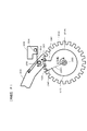
図7は収納位置にある可動体300を斜め前から見たときの演出装置200の部分斜視図、図8は収納位置にある可動体300を斜め後から見たときの演出装置200の部分斜視図、図9は収納位置にある可動体300を前から見たときの演出装置200の部分正面図、図10は収納位置にある可動体300を後から見たときの演出装置200の部分背面図である。
FIG. 7 is a partial perspective view of the rendering device 200 when the movable body 300 in the storage position is viewed from an oblique front, and FIG. 8 is a partial perspective view of the rendering device 200 when the movable body 300 in the storage position is viewed from an oblique rear. 9 is a partial front view of the rendering device 200 when the movable body 300 in the storage position is viewed from the front, and FIG. 10 is a partial back view of the rendering device 200 when the movable body 300 in the storage position is viewed from the rear. FIG.
図3及び図7〜図10に示すように、演出装置200は、ベース部材210、一つの駆動源220、軸状部材230、動力伝達手段240、及び、複数の可動体300を有する。
As shown in FIGS. 3 and 7 to 10, the rendering device 200 includes a base member 210, a single drive source 220, a shaft-like member 230, power transmission means 240, and a plurality of movable bodies 300.
(可動体300、可動集合体300A、300B、300C)
可動体300は、長尺状に形成される。長尺状の可動体300の一例としては、「火縄銃」のミニチュア(小模型)であって、筒(銃身)を有し、一端部は「台カブ」を有し、他端部は筒の銃口を有する。可動体300の一端部に摺接部301が設けられる(図10参照)。摺接部301は、後述する第1カム部CM1、第2カム部CM2に従動するものである。
(Movable body 300, movable assemblies 300A, 300B, 300C)
The movable body 300 is formed in a long shape. An example of the long movable body 300 is a “fire rope” miniature (small model) having a tube (barrel), one end having a “base cub”, and the other end being a tube. Has a muzzle. A sliding contact portion 301 is provided at one end of the movable body 300 (see FIG. 10). The sliding contact portion 301 is driven by a first cam portion CM1 and a second cam portion CM2, which will be described later.
3つの可動体300が表裏方向(前後方向)に配列される。すなわち、3つの可動体300は、表側位置、中央位置、裏側位置にそれぞれ配置される。
Three movable bodies 300 are arranged in the front-back direction (front-rear direction). That is, the three movable bodies 300 are respectively arranged at the front side position, the center position, and the back side position.
表裏方向に配列された3つの可動体300により一つの可動集合体が構成される。演出装置200には3つの可動集合体300A、300B、300Cが用いられる。即ち、可動体300は9(=3×3)個用いられる。これに限らず、可動集合体は複数mであればよく、それを構成する可動体300も複数nであればよい。このとき、可動体300は、m×n個用いられる。可動体300の数の分だけ、それらの動作の組み合わせが多くなり、遊技の興趣が高まる。
One movable assembly is constituted by the three movable bodies 300 arranged in the front-back direction. Three movable assemblies 300A, 300B, and 300C are used for the production device 200. That is, nine (= 3 × 3) movable bodies 300 are used. Not limited to this, the movable assembly may be a plurality of m, and the movable body 300 constituting the movable assembly may be a plurality of n. At this time, m × n movable bodies 300 are used. The number of the movable bodies 300 increases the number of combinations of these operations, and the fun of the game is enhanced.
各可動集合体において、表裏方向(前後方向)に配列された3つの可動体300は、同一の軸状部材230(後述する)により収納位置と目的位置(出現位置)との間を移動可能に支持される。以下の説明において、遊技者側(前)から見て、可動体300の収納位置を遊技盤70の左端部と裏ユニットの左端部との間の位置とし、可動体300の目的位置を収納位置から時計回りに回動させた位置とするとき、「内側」は「右側」となり、「内方向」は「右方向」となる。また、「外側」は、「左側」となり、「外方向」は、「左方向」となる。
In each movable assembly, the three movable bodies 300 arranged in the front and back direction (front-rear direction) can be moved between a storage position and a target position (appearance position) by the same shaft member 230 (described later). Supported. In the following description, when viewed from the player side (front), the storage position of the movable body 300 is the position between the left end portion of the game board 70 and the left end portion of the back unit, and the target position of the movable body 300 is the storage position. “Inside” is “right side”, and “inward direction” is “right direction”. Further, “outside” is “left side”, and “outward direction” is “left direction”.
図9に示すように、3つの可動集合体を、内側に位置するものから順に、内側位置の可動集合体300A、中間位置の可動集合体300B、外側位置の可動集合体300Cという場合がある。可動集合体300A、300B、300Cは、左方向に対して上方向に約40°へ傾けた方向に所定間隔で配列される。すなわち、可動集合体300Bは、可動集合体300Aに対し左上方向に所定量ずれて配置される。さらに、可動集合体300Cは可動集合体300Bに対し左上方向に所定量ずれて配置される。
As shown in FIG. 9, the three movable assemblies may be referred to as an inner position movable assembly 300A, an intermediate position movable assembly 300B, and an outer position movable assembly 300C in order from the inner one. The movable assemblies 300A, 300B, and 300C are arranged at a predetermined interval in a direction inclined upward by about 40 ° with respect to the left direction. That is, the movable assembly 300B is arranged with a predetermined amount shifted in the upper left direction with respect to the movable assembly 300A. Furthermore, the movable assembly 300C is arranged with a predetermined amount shifted in the upper left direction with respect to the movable assembly 300B.
〔ベース部材210〕
次に、ベース部材210について図3、図9、及び図11を参照して説明する。図11はベース部材210内に収容される図9に示す動力伝達手段240(後述する)を下から見たときの底面図である。
[Base member 210]
Next, the base member 210 will be described with reference to FIGS. 3, 9, and 11. FIG. 11 is a bottom view of the power transmission means 240 (described later) shown in FIG. 9 housed in the base member 210 when viewed from below.
図3、図9及び図11に示すように、ベース部材210は、遊技盤70を構成する裏ユニットの左端部に設けられている。ベース部材210は、フロントベース211とリヤベース212と飾りベース213とを有する。フロントベース211は、透光性を備え、底部211a及び壁部211bを有するケース状に形成される。同様に、リヤベース212は、透光性を備え、底部212a及び壁部212bを有するケース状に形成される。底部212aの一部(下端の角部)には、底部212aをケースの内部方向へ窪ませることにより、約25mmの高さを有する段差部212cが形成される。
As shown in FIGS. 3, 9, and 11, the base member 210 is provided at the left end portion of the back unit constituting the game board 70. The base member 210 includes a front base 211, a rear base 212, and a decoration base 213. The front base 211 has translucency and is formed in a case shape having a bottom portion 211a and a wall portion 211b. Similarly, the rear base 212 has translucency and is formed in a case shape having a bottom portion 212a and a wall portion 212b. A stepped portion 212c having a height of about 25 mm is formed on a part of the bottom portion 212a (a corner portion at the lower end) by recessing the bottom portion 212a toward the inside of the case.
また対向する底部211a、212a及び壁部211b、212bにより囲われて収容部214が形成される。壁部211b、212b同士は、突き合わされた状態でネジ止めされる。
In addition, the accommodation portion 214 is formed by being surrounded by the opposed bottom portions 211a and 212a and the wall portions 211b and 212b. The walls 211b and 212b are screwed together in a face-to-face state.
収容部214は幅広部215及び幅狭部216を有する。幅広部215は、約45mmの表裏方向の幅を有し、底部211aと底部212aとの間に形成される。幅狭部216は、約20mmの表裏方向の幅を有し、底部211aと段差部212cとの間に形成される。底部212aと段差部212cとの間の境界線は、図示しないが、可動集合体300A、300B、300Cが配列される方向と一致する。すなわち、境界線は、図9において、左方向に対して上方向へ約40°傾いた直線となる。段差部212cをこのように形成することで、幅広部215に可動集合体300A、300B、300Cを収容可能となり、かつ、後述するように、駆動源220を段差部212cに嵌め込むことが可能となる。なお、段差部212cは、リヤベース212と別体で形成され、リヤベース212に連結されてもよく、リヤベース212と一体的に形成してもよい。
The accommodating part 214 has a wide part 215 and a narrow part 216. The wide portion 215 has a width in the front and back direction of about 45 mm, and is formed between the bottom portion 211a and the bottom portion 212a. The narrow part 216 has a width in the front and back direction of about 20 mm, and is formed between the bottom part 211a and the step part 212c. Although not shown, the boundary line between the bottom portion 212a and the step portion 212c coincides with the direction in which the movable assemblies 300A, 300B, and 300C are arranged. That is, in FIG. 9, the boundary line is a straight line inclined about 40 ° upward with respect to the left direction. By forming the step portion 212c in this way, the movable assemblies 300A, 300B, and 300C can be accommodated in the wide portion 215, and the drive source 220 can be fitted into the step portion 212c as described later. Become. The stepped portion 212c is formed separately from the rear base 212, may be connected to the rear base 212, or may be formed integrally with the rear base 212.
飾りベース213は透光性を有する。飾りベース213を介して、リヤベース212が裏ユニットの左端部に装着される。飾りベース213より後方にベース装飾ランプ(不図示)を設けてもよい。飾りベース213が透光性を有していれば、飾りベース213を透してベース装飾ランプの発光を遊技者に視認させ、興趣を高めることが可能である。
The decoration base 213 has translucency. The rear base 212 is attached to the left end portion of the back unit through the decoration base 213. A base decoration lamp (not shown) may be provided behind the decoration base 213. If the decoration base 213 has translucency, the player can visually recognize the light emitted from the base decoration lamp through the decoration base 213, thereby enhancing the interest.
〔駆動源〕
駆動源220は、例えば電動モータMのような動力を発生するものである。駆動源220は、約28mmの表裏方向の幅をする。駆動源220は、段差部212cに嵌め込まれるように配置される。これにより、駆動源220が配置された所の表裏方向の幅が約48mm(=約20mm+約28mm)となる。これは、約45mmの表裏方向の幅を有する幅広部215と大差がない(図11参照)。したがって、駆動源220が表裏方向で嵩張らないようになる。
[Drive source]
The drive source 220 generates power such as an electric motor M, for example. The driving source 220 has a width in the front-back direction of about 28 mm. The drive source 220 is disposed so as to be fitted into the stepped portion 212c. As a result, the width in the front and back direction where the drive source 220 is disposed is about 48 mm (= about 20 mm + about 28 mm). This is not much different from the wide portion 215 having a width in the front-back direction of about 45 mm (see FIG. 11). Therefore, the drive source 220 is not bulky in the front and back direction.
駆動源220は、ベース部材210に設けられるが、ベース部材210以外の演出装置200の部品または遊技盤70に設けられてもよい。
The drive source 220 is provided on the base member 210, but may be provided on a part of the rendering device 200 other than the base member 210 or on the game board 70.
〔軸状部材230〕
収容部214には、図9に示される3本の軸状部材230、及び、動力伝達手段240が収納される。
[Shaft-shaped member 230]
In the accommodating part 214, the three shaft-like members 230 and the power transmission means 240 shown in FIG. 9 are accommodated.
図9に示すように、3本の軸状部材230は、左方向に対し上方向へ約40°傾けた方向に所定間隔(約37mm)で配置される。すなわち、中央位置の軸状部材230は、右側位置の軸状部材230に対し左上方向に約37mmずれて配置される。さらに、左側位置の軸状部材230は、中央位置の軸状部材230に対し左上方向に約37mmずれて配置される。3本の軸状部材230の配置は、可動集合体300A、300B、300Cが配列される方向及び位置と一致する。
As shown in FIG. 9, the three shaft-like members 230 are arranged at a predetermined interval (about 37 mm) in a direction inclined about 40 ° upward with respect to the left direction. In other words, the shaft-shaped member 230 at the center position is arranged to be shifted by about 37 mm in the upper left direction with respect to the shaft-shaped member 230 at the right position. Further, the shaft-like member 230 at the left side position is disposed with a shift of about 37 mm in the upper left direction with respect to the shaft-like member 230 at the center position. The arrangement of the three shaft-like members 230 matches the direction and position in which the movable assemblies 300A, 300B, and 300C are arranged.
このように、左上方向に約37mm間隔で、可動集合体300A、300B、300C、各軸状部材230が配置されるため、各可動体300が長尺方向を上下方向にして収納される収納位置では、各可動集合体間で可動体300同士が互いに干渉せず、さらに、各可動体300が長尺方向を左右方向にして出現される目的位置では、各可動集合体間で可動体300同士が互いに干渉しない。さらに、後述するが、可動体300を収納位置から目的位置に移動させるとき、内側位置(ここでは右側位置または下段側位置)の可動集合体300Aから順番におこなうため、各可動集合体間で可動体300同士が互いに干渉しない。さらに、可動体300を目的位置から収納位置に移動させるとき、外側位置(ここでは左側位置または上段側位置)の可動集合体300Cから順番に行うため、各可動集合体間で可動体300同士が互いに干渉しない。さらに、各可動体300を同時に目的位置から収納位置に移動させるときも、各可動体300が互いに干渉しない。
As described above, the movable assemblies 300A, 300B, 300C and the respective shaft-like members 230 are arranged at intervals of about 37 mm in the upper left direction. Therefore, the storage positions in which the movable bodies 300 are stored with the longitudinal direction being the vertical direction. Then, the movable bodies 300 do not interfere with each other between the movable assemblies, and further, at the target position where the movable bodies 300 appear with the longitudinal direction set to the left-right direction, the movable bodies 300 are between the movable assemblies. Do not interfere with each other. Further, as will be described later, when the movable body 300 is moved from the storage position to the target position, the movable body 300A is moved in order from the movable assembly 300A at the inner position (here, the right side position or the lower position). The bodies 300 do not interfere with each other. Further, when the movable body 300 is moved from the target position to the storage position, the movable bodies 300 are moved in order from the movable aggregate 300C at the outer position (here, the left position or the upper stage position). Do not interfere with each other. Further, when the movable bodies 300 are simultaneously moved from the target position to the storage position, the movable bodies 300 do not interfere with each other.
なお上記構成において可動集合体300Aは、内側位置における、表側位置の可動体300(後述のA1)、中央位置の可動体300(後述のA2)及び裏側位置の可動体300(後述のA3)を有して構成される。また、可動集合体300Bは、内側位置における、表側位置の可動体300(後述のB1)、中央位置の可動体300(後述のB2)及び裏側位置の可動体300(後述のB3)を有して構成される。また、可動集合体300Cは、内側位置における、表側位置の可動体300(後述のC1)、中央位置の可動体300(後述のC2)及び裏側位置の可動体300(後述のC3)を有して構成される。
In the above configuration, the movable assembly 300A includes a front-side movable body 300 (described later A1), a central-position movable body 300 (described later A2), and a rear-side movable body 300 (described later A3) in the inner position. It is configured. In addition, the movable assembly 300B includes a movable body 300 (B1 described later) at the front side position, a movable body 300 (B2 described later) at the center position, and a movable body 300 (B3 described later) at the back side position. Configured. In addition, the movable assembly 300C has a movable body 300 (described later, C1), a movable body 300 (described later, C2) at the center position, and a movable body 300 (described later, C3) at the back position, at the inner side position. Configured.
ただし、本実施形態の遊技機1はこれに限らず、第1カム部CM1、第2カム部CM2を円周方向の所定の位置に設けることにより、内側位置、中間位置及び外側位置それぞれにおける表側位置の可動体300(A1,B1,C1)を1つの可動集合体として構成することが可能である。この場合、同様に内側位置、中間位置及び外側位置それぞれにおける中央位置の可動体300(A2,B2,C2)を1つの可動集合体として構成し、かつ内側位置、中間位置及び外側位置それぞれにおける裏側位置の可動体300(A3,B3,C3)を1つの可動集合体として構成することが可能である。
However, the gaming machine 1 of the present embodiment is not limited to this, and by providing the first cam portion CM1 and the second cam portion CM2 at predetermined positions in the circumferential direction, the front side at each of the inner position, the intermediate position, and the outer position. The movable body 300 (A1, B1, C1) at the position can be configured as a single movable assembly. In this case, similarly, the movable body 300 (A2, B2, C2) at the center position at each of the inner position, the intermediate position, and the outer position is configured as one movable assembly, and the back side at each of the inner position, the intermediate position, and the outer position. The movable body 300 (A3, B3, C3) at the position can be configured as one movable assembly.
この構成においても、各可動集合体における各可動体300を、それぞれタイミングをずらして目的位置から収納位置に移動させるとき、可動体300同士が互いに干渉しない。さらに、各可動体300を同時に目的位置から収納位置に移動させるときも、各可動体300が互いに干渉しない。
Also in this configuration, when each movable body 300 in each movable assembly is moved from the target position to the storage position at different timings, the movable bodies 300 do not interfere with each other. Further, when the movable bodies 300 are simultaneously moved from the target position to the storage position, the movable bodies 300 do not interfere with each other.
可動集合体300A、300B、300Cにおいて、それらを構成する3つの可動体300が一つの軸状部材230により軸支される構造は同じであるため、軸支構造の一つを代表して説明する。
In the movable assemblies 300A, 300B, and 300C, the structure in which the three movable bodies 300 constituting them are pivotally supported by one shaft-like member 230 is the same, so that one of the pivotal support structures will be described as a representative. .
図11に示すように、軸状部材230が配置される位置に対応して、底部211a、212aには軸受部211d、212dが形成される。軸受部211d、212dは、ケースの内部方向に約2mmだけ突出させたボス部211e、212eを有する。ボス部211e、212eには、軸状部材230が嵌め込まれる穴を有する。軸状部材230は、底部211a、212a間に架け渡される。軸状部材230の両端部がボス部211e、212eの穴に嵌め込まれる。それにより、表裏方向に配列された3つの可動体300が、一つの軸状部材230により遊技盤70における収納位置と目的位置(出現位置)との間を移動可能に軸支される。軸状部材230の端部が嵌め込まれる軸受部211dのボス部211eを図21及び図22に示す。
As shown in FIG. 11, bearing portions 211d and 212d are formed on the bottom portions 211a and 212a corresponding to the positions where the shaft-like members 230 are disposed. The bearing portions 211d and 212d have boss portions 211e and 212e that protrude by about 2 mm in the inner direction of the case. The boss portions 211e and 212e have holes into which the shaft-like member 230 is fitted. The shaft-shaped member 230 is bridged between the bottom portions 211a and 212a. Both end portions of the shaft-shaped member 230 are fitted into the holes of the boss portions 211e and 212e. Thereby, the three movable bodies 300 arranged in the front and back directions are pivotally supported by one shaft-like member 230 so as to be movable between the storage position and the target position (appearance position) on the game board 70. 21 and 22 show a boss 211e of the bearing 211d into which the end of the shaft member 230 is fitted.
〔動力伝達手段〕
次に、動力伝達手段240について図4、図7〜図17を参照して説明する。
[Power transmission means]
Next, the power transmission means 240 will be described with reference to FIGS. 4 and 7 to 17.
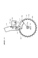
図12は大部分の可動体が目的位置に移動したときの演出装置を後から見たときの背面図、図13は大部分の可動体が目的位置に移動したときの演出装置を斜め前から見たときの斜視図、図14は一部の可動体が目的位置に移動したときの演出装置を後から見たときの背面図、図15は一部の可動体が目的位置に移動したときの演出装置を斜め前から見たときの斜視図、図16は目的位置にある可動体を後から見たときの演出装置の部分背面図、図17は可動体の動作を示すタイミングチャートである。
12 is a rear view of the rendering device when most of the movable bodies are moved to the target position, and FIG. 13 is a rear view of the rendering device when most of the movable bodies are moved to the target position. FIG. 14 is a rear view of the rendering device when a part of the movable body is moved to the target position, and FIG. 15 is a rear view when the part of the movable body is moved to the target position. FIG. 16 is a partial rear view of the rendering device when the movable body at the target position is viewed from the rear, and FIG. 17 is a timing chart showing the operation of the movable body. .
図4、図8〜図11に示すように、動力伝達手段240は、原動ギア241、軸状部材250a、軸状部材250b、第1中継ギア251、第2中継ギア252、軸状部材260、3つのドラム270A、270B、270Cを有する。3つのドラム270A、270B、270Cの配列方向は、図9において左方向に対して上方向へ約40°傾いた方向となる。この方向は、可動集合体300A、300B、300Cが配列される方向と一致する。
As shown in FIGS. 4 and 8 to 11, the power transmission means 240 includes a driving gear 241, a shaft member 250 a, a shaft member 250 b, a first relay gear 251, a second relay gear 252, a shaft member 260, It has three drums 270A, 270B, 270C. The arrangement direction of the three drums 270A, 270B, and 270C is a direction inclined about 40 ° upward with respect to the left direction in FIG. This direction coincides with the direction in which the movable assemblies 300A, 300B, and 300C are arranged.
(中継ギア、軸状部材)
第1中継ギア251は、軸状部材250aにより軸支される。第2中継ギア252は、軸状部材250bにより軸支される。軸状部材250a、軸状部材250bの軸支構造は、軸状部材230の軸支構造と同じである。すなわち、軸状部材250はa、軸状部材250b、底部211a、212a間に架け渡される。軸状部材250a、軸状部材250bそれぞれの両端部がボス部211e、212eの穴にそれぞれ嵌め込まれる(図11参照)。
(Relay gear, shaft-shaped member)
The first relay gear 251 is pivotally supported by the shaft-like member 250a. The second relay gear 252 is pivotally supported by the shaft-like member 250b. The shaft support structure of the shaft member 250 a and the shaft member 250 b is the same as the shaft support structure of the shaft member 230. That is, the shaft-shaped member 250 is bridged between a, the shaft-shaped member 250b, and the bottom portions 211a and 212a. Both end portions of the shaft-shaped member 250a and the shaft-shaped member 250b are fitted into the holes of the boss portions 211e and 212e, respectively (see FIG. 11).
なお、第1中継ギア251、第2中継ギア252及びこれらの軸支構造は同一である。それにより、コストの削減を図ることができる。
In addition, the 1st relay gear 251, the 2nd relay gear 252, and these shaft support structures are the same. Thereby, cost can be reduced.
(ドラム)
内側位置のドラム270Aは、軸状部材260により軸支されることで回転可能に構成される。中間位置のドラム270Bは、軸状部材260により軸支される。外側位置のドラム270Cは、軸状部材260により軸支される。なお、軸状部材260の配列方向も可動集合体300A、300B、300Cが配列される方向と一致する。
(drum)
The drum 270 </ b> A at the inner position is configured to be rotatable by being pivotally supported by the shaft-like member 260. The drum 270 </ b> B at the intermediate position is supported by the shaft-shaped member 260. The outer side drum 270 </ b> C is pivotally supported by a shaft-like member 260. Note that the arrangement direction of the shaft-like members 260 also coincides with the direction in which the movable assemblies 300A, 300B, and 300C are arranged.
軸状部材260の軸支構造は、軸状部材230の軸支構造と同じである。すなわち、軸状部材260は、底部211a、212a間に架け渡される。軸状部材260の両端部がボス部211e、212eの穴に嵌め込まれる(図11参照)。
The shaft support structure of the shaft member 260 is the same as the shaft support structure of the shaft member 230. That is, the shaft-shaped member 260 is bridged between the bottom portions 211a and 212a. Both end portions of the shaft-like member 260 are fitted into the holes of the boss portions 211e and 212e (see FIG. 11).
内側位置のドラム270AはドラムギアDGAを有している。中間位置のドラム270Bは、ドラムギアDGBを有している。外側位置のドラム270Cは、ドラムギアDGCを有している。
The drum 270A at the inner position has a drum gear DGA. The drum 270B at the intermediate position has a drum gear DGB. The drum 270C at the outer position has a drum gear DGC.
なお、ドラムギアDGA、DGB、DGCは同一の構造を有しており(例えば、ドラムギアのピッチ円直径と歯数が同じ)、さらに、ドラム270A、270B、270Cをそれぞれ回転させるときの周速は同じである。それにより、コストの削減を図ることができる。さらに、ドラム270A、270B、270Cの回転角度θa、θb、θcが同一となり(θa=θb=θc)、可動体300間の相対的なタイミングを生成するために、後述する第1カム部CM1及び第2カム部CM2を設けるとき、それらの位置を決め易い構造となる(図9、図10参照)。
The drum gears DGA, DGB, and DGC have the same structure (for example, the drum gear has the same pitch circle diameter and the same number of teeth), and the peripheral speeds when the drums 270A, 270B, and 270C are rotated are the same. It is. Thereby, cost can be reduced. Further, the rotation angles θa, θb, and θc of the drums 270A, 270B, and 270C are the same (θa = θb = θc), and in order to generate a relative timing between the movable bodies 300, a first cam portion CM1 and When the second cam portion CM2 is provided, the position thereof can be easily determined (see FIGS. 9 and 10).
(原動ギア241)
図9〜図11に示すように、原動ギア241は、電動モータMの出力軸に固定されている。原動ギア241には第1中継ギア251が噛み合っている。第1中継ギア251には、ドラムギアDGA及びドラムギアDGBが噛み合っている。演出装置200を後から見た図10において、原動ギア241(図9参照)が時計回りに回転すると(電動モータMが時計回りに回転すると)、第1中継ギア251が反時計回りに回転するため、ドラムギアDGA、DGBが時計回りに回転する。それにより、ドラム270A、270Bが時計回りに回転する。
(Driving gear 241)
As shown in FIGS. 9 to 11, the driving gear 241 is fixed to the output shaft of the electric motor M. The first relay gear 251 is engaged with the driving gear 241. The first relay gear 251 meshes with the drum gear DGA and the drum gear DGB. In FIG. 10 when the rendering device 200 is viewed later, when the driving gear 241 (see FIG. 9) rotates clockwise (when the electric motor M rotates clockwise), the first relay gear 251 rotates counterclockwise. Therefore, the drum gears DGA and DGB rotate clockwise. As a result, the drums 270A and 270B rotate clockwise.
ドラムギアDGBには第2中継ギア252が噛み合っている。第2中継ギア252にはドラムギアDGCが噛み合っている。図10において、ドラムギアDGBが時計回りに回転すると、第2中継ギア252が反時計回りに回転するため、ドラムギアDGCが時計回りに回転する。それにより、ドラム270Cが時計回りに回転する。
The second relay gear 252 meshes with the drum gear DGB. The second relay gear 252 meshes with the drum gear DGC. In FIG. 10, when the drum gear DGB rotates clockwise, the second relay gear 252 rotates counterclockwise, so that the drum gear DGC rotates clockwise. Thereby, the drum 270C rotates clockwise.
即ち、図10において、原動ギア241が時計回りに回転すると、ドラムギアDGA、DGB、DGCが時計回りに回転する。それにより、ドラム270A、270B、270Cが時計回りに回転する。反対に、原動ギア241が反時計回りに回転すると、ドラムギアDGA、DGB、DGCが反時計回りに回転する。それにより、ドラム270A、270B、270Cが反時計回りに回転する。なお、ドラム270A、270B、270Cは互いに同じ回転速度で時計回り/反時計回りに回転する。
That is, in FIG. 10, when the driving gear 241 rotates clockwise, the drum gears DGA, DGB, DGC rotate clockwise. Thereby, the drums 270A, 270B, and 270C rotate clockwise. In contrast, when the driving gear 241 rotates counterclockwise, the drum gears DGA, DGB, DGC rotate counterclockwise. Thereby, the drums 270A, 270B, and 270C rotate counterclockwise. The drums 270A, 270B, and 270C rotate clockwise / counterclockwise at the same rotational speed.
さらに、以下の説明で、ドラム270A、270B、270Cの回転方向及び回転角度を、図10に示すように、演出装置200を後から見たときの方向及び角度とし、第1の方向への変位である時計回りを「正回転」という場合があり、逆方向である第2の方向への変位である反時計回りを「逆回転」という場合がある。
Further, in the following description, the rotation direction and rotation angle of the drums 270A, 270B, and 270C are the direction and angle when the rendering device 200 is viewed from the rear as shown in FIG. In some cases, clockwise rotation is referred to as “forward rotation”, and counterclockwise rotation, which is displacement in the second direction, which is the reverse direction, may be referred to as “reverse rotation”.
内側位置のドラム270Aの外周面には、表側位置、中央位置、および、裏側位置に配列された3つの可動体300に対応する3つの周面カムが設けられる。したがって、3つの周面カムも、表側位置、中央位置、および、裏側位置に配列される。各周面カムは、小径部C11、C12、C13、大径部C21、C22、C23、第1カム部CM1、および、第2カム部CM2を有する。周方向に、小径部C11、C12、C13、第2カム部CM2、大径部C21、C22、C23、および、第1カム部CM1の順に配列される。大径部C21、C22、C23と軸状部材260(ドラムの回転中心)との間の距離は、小径部C11、C12、C13のそれより約6mm長い。大径部C21、C22、C23は、例えば、可動体300の摺接部301と直接接し、後述する付勢力に抗って可動体300を駆動する接触面の機能を有する。この接触面のことは、ドラム270Aに限定されず、ドラム270B、ドラム270Cの場合においても同じである。
Three peripheral cams corresponding to the three movable bodies 300 arranged at the front side position, the center position, and the back side position are provided on the outer peripheral surface of the drum 270A at the inner position. Accordingly, the three circumferential cams are also arranged at the front side position, the center position, and the back side position. Each peripheral cam has small diameter portions C11, C12, C13, large diameter portions C21, C22, C23, a first cam portion CM1, and a second cam portion CM2. In the circumferential direction, the small diameter portions C11, C12, C13, the second cam portion CM2, the large diameter portions C21, C22, C23, and the first cam portion CM1 are arranged in this order. The distances between the large diameter portions C21, C22, C23 and the shaft-like member 260 (drum rotation center) are approximately 6 mm longer than those of the small diameter portions C11, C12, C13. The large diameter portions C21, C22, and C23, for example, are in direct contact with the sliding contact portion 301 of the movable body 300 and have a function of a contact surface that drives the movable body 300 against an urging force described later. This contact surface is not limited to the drum 270A, and the same applies to the drums 270B and 270C.
(第1カム部)
次に、内側位置のドラム270Aに設けられる第1カム部CM1について図10を参照して説明する。図10は、後(裏)から見たときの演出装置200の部分背面図である。図10において紙面の奥側が「表側」であり、紙面の手前側が「裏側」である。
(First cam part)
Next, the first cam portion CM1 provided on the drum 270A at the inner position will be described with reference to FIG. FIG. 10 is a partial rear view of the rendering device 200 when viewed from the back (back). In FIG. 10, the back side of the page is the “front side”, and the front side of the page is the “back side”.
図10に示すように、3つの第1カム部CM1は、表側位置、中央位置、および、裏側位置に配置される。表側位置の第1カム部CM1は、表側位置の外周面である小径部C11と大径部C21とを連絡する傾斜面部である。さらに、中央位置の第1カム部CM1は、中央位置の外周面である小径部C12と大径部C22とを連絡する傾斜面部である。さらに、裏側位置の第1カム部CM1は、ドラム270Aにおける裏側位置の外周面である小径部C13と大径部C23とを連絡する傾斜面部である。
As shown in FIG. 10, the three first cam portions CM1 are arranged at the front side position, the center position, and the back side position. The first cam portion CM1 at the front side position is an inclined surface portion that connects the small diameter portion C11 and the large diameter portion C21 that are outer peripheral surfaces at the front side position. Further, the first cam portion CM1 at the central position is an inclined surface portion that connects the small diameter portion C12 and the large diameter portion C22 that are outer peripheral surfaces at the central position. Further, the first cam portion CM1 at the back side position is an inclined surface portion that connects the small diameter portion C13 and the large diameter portion C23 that are outer peripheral surfaces at the back side position in the drum 270A.
3つの第1カム部CM1は、ドラム270Aの周方向の位置を同じにして設けられる。図17の例においては、3つの第1カム部CM1の位置が、ドラム270Aの周方向における基準位置(360°=0°)に設定されている。なお、周方向における基準位置については任意に設定することが可能である。
The three first cam portions CM1 are provided with the same circumferential position of the drum 270A. In the example of FIG. 17, the positions of the three first cam portions CM1 are set to the reference position (360 ° = 0 °) in the circumferential direction of the drum 270A. The reference position in the circumferential direction can be arbitrarily set.
表側位置の第1カム部CM1は、表側位置の可動体300の摺接部301に対応して配置される。中央位置の第1カム部CM1は、中央位置の可動体300の摺接部301に対応して配置される。裏側位置の第1カム部CM1は、裏側位置の可動体300の摺接部301に対応して配置される。
The first cam portion CM1 at the front side position is disposed corresponding to the sliding contact portion 301 of the movable body 300 at the front side position. The first cam portion CM1 at the center position is disposed corresponding to the sliding contact portion 301 of the movable body 300 at the center position. The first cam portion CM1 at the back side position is disposed corresponding to the sliding contact portion 301 of the movable body 300 at the back side position.
ドラム270Aが図10において時計回りに回転(正回転)し、第1カム部CM1に、内側位置の可動集合体300Aに属する表側位置の可動体300の摺接部301を従動させると、表側位置の可動体300が収納位置に移動されるように構成される。さらに、第1カム部CM1に、内側位置の可動集合体300Aに属する中央位置の可動体300の摺接部301を従動させると、中央位置の可動体300が収納位置に移動されるように構成される。さらに、第1カム部CM1に、内側位置の可動集合体300Aに属する裏側位置の可動体300の摺接部301を従動させると、裏側位置の可動体300が収納位置に移動されるように構成される。これら3つの可動体300は、上記の時に3つの第1カム部CM1の周方向の位置が同じであるから、同時に収納される。
When the drum 270A rotates clockwise in FIG. 10 (forward rotation), and the sliding contact portion 301 of the movable body 300 at the front side position belonging to the movable assembly 300A at the inner position is driven by the first cam portion CM1, the front side position The movable body 300 is configured to be moved to the storage position. Further, when the sliding contact portion 301 of the central movable body 300 belonging to the inner movable assembly 300A is driven by the first cam portion CM1, the central movable body 300 is moved to the storage position. Is done. Further, when the first cam portion CM1 is driven by the sliding contact portion 301 of the movable body 300 at the back side position belonging to the movable assembly 300A at the inner position, the movable body 300 at the back side position is moved to the storage position. Is done. These three movable bodies 300 are housed simultaneously because the circumferential positions of the three first cam portions CM1 are the same at the time described above.
ここで、「第1カム部に摺接部を従動させる」とは、第1カム部に摺接部が実際に接しているかどうかを問わない。第1カム部に摺接部が接していないときは、可動体300を例えば付勢力(後述するばね部材302による付勢力)により収納位置に移動させることになる。すなわち、第1カム部の正逆方向の回転動作に摺接部が追従する動作が従動に相当する。第1カム部に摺接部が実際に接しているときは、第1カム部が、可動体300を強制的に収納位置に移動させる「確動カム」の機能を有する。
Here, “the sliding contact portion is driven by the first cam portion” does not matter whether the sliding contact portion is actually in contact with the first cam portion. When the sliding contact portion is not in contact with the first cam portion, the movable body 300 is moved to the storage position by, for example, a biasing force (a biasing force by a spring member 302 described later). That is, the operation in which the sliding contact portion follows the rotation operation of the first cam portion in the forward / reverse direction corresponds to the follower. When the sliding contact portion is actually in contact with the first cam portion, the first cam portion has a function of “positive cam” for forcibly moving the movable body 300 to the storage position.
図3及び図7〜図10は、表側位置、中央位置、及び、裏側位置の各可動体300が収納位置に移動されたときの図である。図3及び図7〜図10に示すように、収納位置では、表側位置の可動体300の長尺方向、中央位置の可動体300の長尺方向、裏側位置の可動体300の長尺方向は、数度ずつずれている。したがって、収納位置において、3本の可動体300が前後方向において完全に重ならないため、遊技者により視認することが可能となる。
3 and 7 to 10 are views when the movable bodies 300 at the front side position, the center position, and the back side position are moved to the storage position. As shown in FIGS. 3 and 7 to 10, in the storage position, the longitudinal direction of the movable body 300 at the front side position, the longitudinal direction of the movable body 300 at the center position, and the longitudinal direction of the movable body 300 at the back side position are , Are shifted by several degrees. Accordingly, since the three movable bodies 300 do not completely overlap in the front-rear direction at the storage position, the player can visually recognize them.
(第2カム部)
次に、内側位置のドラム270Aに設けられる第2カム部CM2について図10を参照して説明する。
(Second cam part)
Next, the second cam portion CM2 provided on the drum 270A at the inner position will be described with reference to FIG.
3つの第2カム部CM2は、表側位置、中央位置、および、裏側位置に配置される。なお、第2カム部CM2は、第1カム部CM1とはドラムの周方向で異なる位置に配置されることは前述した通りである。
The three second cam portions CM2 are disposed at the front side position, the center position, and the back side position. As described above, the second cam portion CM2 is disposed at a different position from the first cam portion CM1 in the circumferential direction of the drum.
図10に示すように、表側位置の第2カム部CM2は、表側位置の外周面である小径部C11と大径部C21とを連絡する傾斜面部である。さらに、中央位置の第2カム部CM2は、中央位置の外周面である小径部C12と大径部C22とを連絡する傾斜面部である。さらに、裏側位置の第2カム部CM2は、ドラム270Aにおける裏側位置の外周面である小径部C13と大径部C23とを連絡する傾斜面部である。
As shown in FIG. 10, the second cam portion CM2 at the front side position is an inclined surface portion that connects the small diameter portion C11 and the large diameter portion C21 that are outer peripheral surfaces at the front side position. Further, the second cam portion CM2 at the center position is an inclined surface portion that connects the small diameter portion C12 and the large diameter portion C22 that are outer peripheral surfaces at the center position. Further, the second cam portion CM2 at the back side position is an inclined surface portion that connects the small diameter portion C13 and the large diameter portion C23, which are outer peripheral surfaces at the back side position in the drum 270A.
3つの第2カム部CM2は、ドラム270Aの周方向の位置を互いに異ならせて、かつ、表裏方向(前後方向)に配置される。ここで、「周方向の位置を互いに異ならせ」とは、ドラム270Aが所定の回転角度になったときの位置でいえば、図17に示す(約75°〜約90°)、(約90°〜約105°)、(約105°〜約120°)の位置のように異なることをいう。
The three second cam portions CM2 are arranged in the front-back direction (front-rear direction) with the circumferential positions of the drum 270A different from each other. Here, “the positions in the circumferential direction differ from each other” means the position when the drum 270A is at a predetermined rotation angle (about 75 ° to about 90 °) shown in FIG. (About 105 °) and (about 105 ° to about 120 °).
表側位置の第2カム部CM2は、表側位置の可動体300の摺接部301に対応して配置される。中央位置の第2カム部CM2は、中央位置の可動体300の摺接部301に対応して配置される。裏側位置の第2カム部CM2は、裏側位置の可動体300の摺接部301に対応して配置される。
The second cam portion CM2 at the front side position is arranged corresponding to the sliding contact portion 301 of the movable body 300 at the front side position. The second cam portion CM2 at the center position is disposed corresponding to the sliding contact portion 301 of the movable body 300 at the center position. The second cam portion CM2 at the back side position is disposed corresponding to the sliding contact portion 301 of the movable body 300 at the back side position.
ドラム270Aが図10において時計回りに回転(正回転)し、第2カム部CM2に表側位置の可動体300の摺接部301を従動させることにより、表側位置の可動体300が収納位置から目的位置(出現位置)に移動されるように構成される。さらに、ドラム270Aが図10において時計回りに回転(正回転)し、第2カム部CM2に中央位置の可動体300の摺接部301を従動させることにより、中央位置の可動体300が収納位置から目的位置(出現位置)に移動されるように構成される。さらに、ドラム270Aが図10において時計回りに回転(正回転)し、第2カム部CM2に裏側位置の可動体300の摺接部301を従動させることにより、裏側位置の可動体300が収納位置から目的位置(出現位置)に移動されるように構成される。これら3つの可動体300は、上記の時に3つの第2カム部CM2の周方向の位置が異なるから、異なる時に出現される。
The drum 270A rotates clockwise (forward rotation) in FIG. 10, and the sliding contact portion 301 of the movable body 300 at the front side position is driven by the second cam portion CM2, so that the movable body 300 at the front side position is moved from the storage position to the target. It is configured to be moved to a position (appearance position). Further, the drum 270A rotates clockwise in FIG. 10 (forward rotation), and the sliding contact portion 301 of the central movable body 300 is driven by the second cam portion CM2, so that the central movable body 300 is stored. To the target position (appearance position). Furthermore, the drum 270A rotates clockwise in FIG. 10 (forward rotation), and the sliding contact portion 301 of the movable body 300 at the back side position is driven by the second cam portion CM2, so that the movable body 300 at the back side position is in the storage position. To the target position (appearance position). These three movable bodies 300 appear at different times because the circumferential positions of the three second cam portions CM2 are different at the above time.
反対に、ドラム270Aが図10において反時計回りに回転(逆回転)し、第2カム部CM2に表側位置の可動体300の摺接部301を従動させることにより、表側位置の可動体300が目的位置(出現位置)から収納位置に移動されるように構成される。さらに、ドラム270Aが図10において反時計回りに回転(逆回転)し、第2カム部CM2に中央位置の可動体300の摺接部301を従動させることにより、中央位置の可動体300が目的位置(出現位置)から収納位置に移動されるように構成される。さらに、反対に、ドラム270Aが図10において反時計回りに回転(逆回転)し、第2カム部CM2に裏側位置の可動体300の摺接部301を従動させることにより、裏側位置の可動体300が目的位置(出現位置)から収納位置に移動されるように構成される。これら3つの可動体300は、上記の時に3つの第2カム部CM2の周方向の位置が異なるから、異なる時に収納される。
On the other hand, the drum 270A rotates counterclockwise in FIG. 10 (reverse rotation), and the sliding contact portion 301 of the movable body 300 at the front side position is driven by the second cam portion CM2, whereby the movable body 300 at the front side position is moved. It is configured to be moved from the target position (appearance position) to the storage position. Further, the drum 270A rotates counterclockwise in FIG. 10 (reverse rotation), and the sliding contact portion 301 of the movable body 300 at the central position is driven by the second cam portion CM2. It is configured to be moved from the position (appearance position) to the storage position. Further, on the other hand, the drum 270A rotates counterclockwise in FIG. 10 (reverse rotation), and the sliding contact portion 301 of the movable body 300 at the back side position is driven by the second cam portion CM2, thereby moving the movable body at the back side position. 300 is configured to be moved from the target position (appearance position) to the storage position. These three movable bodies 300 are stored at different times because the circumferential positions of the three second cam portions CM2 are different at the time described above.
ここで、「第2カム部に摺接部を従動させる」とは、第2カム部に摺接部が実際に接しているかどうかを問わない。第2カム部に摺接部が接していないときは、可動体300を例えば付勢力(後述するばね部材302による付勢力)により収納位置に移動させることになる。すなわち、第2カム部の正逆方向の回転動作に摺接部が追従する動作が従動に相当する。第2カム部に摺接部が実際に接しているときは、第2カム部が、可動体300を強制的に収納位置に移動させる「確動カム」の機能を有する。
Here, “to make the sliding contact portion follow the second cam portion” does not matter whether the sliding contact portion is actually in contact with the second cam portion. When the sliding contact portion is not in contact with the second cam portion, the movable body 300 is moved to the storage position by an urging force (an urging force by a spring member 302 described later), for example. That is, the operation in which the sliding contact portion follows the rotation operation in the forward and reverse directions of the second cam portion corresponds to the follower. When the sliding contact portion is actually in contact with the second cam portion, the second cam portion has a function of “positive cam” for forcibly moving the movable body 300 to the storage position.
図4及び図16は、表側位置、中央位置、及び、裏側位置の各可動体300が目的位置(出現位置)に移動されたときの図である。図4に示すように、目的位置では、表側位置の可動体300の長尺方向、中央位置の可動体300の長尺方向、裏側位置の可動体300の長尺方向は、数度ずつずれている。それにより、目的位置において、3本の可動体300が完全に重ならないため、遊技者により視認することが可能となる。
4 and 16 are diagrams when the movable bodies 300 at the front side position, the center position, and the back side position are moved to the target position (appearance position). As shown in FIG. 4, at the target position, the longitudinal direction of the movable body 300 at the front side position, the longitudinal direction of the movable body 300 at the center position, and the longitudinal direction of the movable body 300 at the back side position are shifted by several degrees. Yes. Thereby, since the three movable bodies 300 do not completely overlap at the target position, the player can visually recognize them.
(第1カム部CM1、第2カム部CM2)
図10に示すように、ドラム270Aの外周面には、表裏方向に3つの周面カムが配列される。周面カムには、小径部C11、C12、C13、大径部C21、C22、C23、第1カム部CM1及び、第2カム部CM2が設けられる。
(First cam part CM1, second cam part CM2)
As shown in FIG. 10, three circumferential cams are arranged on the outer circumferential surface of the drum 270A in the front and back direction. The circumferential cam is provided with small diameter portions C11, C12, C13, large diameter portions C21, C22, C23, a first cam portion CM1, and a second cam portion CM2.
第1カム部CM1、第2カム部CM2の傾きを、「外周面に接する線に対する傾き」と定義するならば、第1カム部CM1、第2カム部CM2の傾きは、40°から90°であることが好ましい。なお、この場合外周面とは大径部C21等の外周面をいう。また、第1カム部CM1、第2カム部CM2の傾きを緩くすることにより、可動体300を低速で移動させることが可能となる。反対に、第1カム部CM1、第2カム部CM2の傾きを急にすることにより、可動体300を高速で移動させることが可能となる。それにより、可動体300の移動速度に変化をつけて、遊技の興趣を高めることが可能となる。
If the inclinations of the first cam part CM1 and the second cam part CM2 are defined as “inclination with respect to a line in contact with the outer peripheral surface”, the inclinations of the first cam part CM1 and the second cam part CM2 are 40 ° to 90 °. It is preferable that In this case, the outer peripheral surface means an outer peripheral surface such as the large diameter portion C21. In addition, the movable body 300 can be moved at a low speed by reducing the inclination of the first cam portion CM1 and the second cam portion CM2. On the other hand, the movable body 300 can be moved at high speed by making the inclination of the first cam portion CM1 and the second cam portion CM2 steep. Thereby, it is possible to increase the interest of the game by changing the moving speed of the movable body 300.
なお、第1カム部CM1、第2カム部CM2の傾きを40°以上としたのは、40°未満では、ドラムの一回転(360°)の中で、9つの可動体300を収納位置と目的位置との間に移動させることが困難となるためである。
The inclination of the first cam portion CM1 and the second cam portion CM2 is set to 40 ° or more. If the tilt is less than 40 °, the nine movable bodies 300 are set as the storage positions within one rotation (360 °) of the drum. This is because it becomes difficult to move the target position.
ここで、第1カム部CM1、第2カム部CM2の傾きを急にしたときの対策について説明する。第1カム部CM1、第2カム部CM2の傾きを急(例えば、70°〜90°)にすると、摺接部301に大きな負荷がかかり、損傷するおそれがある。これを防止するためには、(1)後述する動力伝達阻止手段を設けることにより、第1カム部CM1、第2カム部CM2の手前位置で摺接部301の動きを止めるように、駆動源220から可動体300への動力の伝達を阻止することにより、ドラムの回転を阻止すればよい。(2)摺接部301に、第1カム部CM1、第2カム部CM2を転がる転動用ローラを設けることにより、摺接部301に対する負荷を軽減すればよい。(3)摺接部301が第1カム部CM1から第2カム部CM2に容易に乗り上がるように、摺接部301に、例えば、第1カム部CM1と第2カム部CM2との段差分を超える大きさの径の丸みをつければよい。(4)第1カム部CM1、第2カム部CM2の傾きを緩く、例えば、70°未満にすればよい。
Here, a countermeasure when the inclination of the first cam portion CM1 and the second cam portion CM2 is steep will be described. When the inclination of the first cam portion CM1 and the second cam portion CM2 is steep (for example, 70 ° to 90 °), a large load is applied to the sliding contact portion 301, which may be damaged. In order to prevent this, (1) a driving source is provided so as to stop the movement of the sliding contact portion 301 at a position in front of the first cam portion CM1 and the second cam portion CM2 by providing a power transmission blocking means described later. The rotation of the drum may be prevented by preventing the transmission of power from 220 to the movable body 300. (2) By providing the sliding contact portion 301 with rolling rollers that roll the first cam portion CM1 and the second cam portion CM2, the load on the sliding contact portion 301 may be reduced. (3) For example, the sliding contact portion 301 has a step difference between the first cam portion CM1 and the second cam portion CM2 so that the sliding contact portion 301 can easily ride on the second cam portion CM2 from the first cam portion CM1. What is necessary is just to give the roundness of the diameter of exceeding. (4) The inclination of the first cam part CM1 and the second cam part CM2 may be made gentle, for example, less than 70 °.
(当接部材)
図11に示すように、底部211aと底部212aとの間に架け渡されるように3つの当接部材303が設けられる。3つの当接部材303は、表側位置、中央位置、裏側位置の各可動体300(または摺接部301)に対応して配置される。
(Contact member)
As shown in FIG. 11, three contact members 303 are provided so as to be bridged between the bottom part 211a and the bottom part 212a. The three contact members 303 are arranged corresponding to the movable bodies 300 (or the sliding contact portions 301) at the front side position, the center position, and the back side position.
図18は、可動体300を目的位置に移動させたとき動力伝達手段の一部を後から見た模式図、図19は、可動体300を収納位置に移動させたとき動力伝達手段の一部を後から見た模式図である。図18及び図19に示すように、当接部材303に各可動体300(または摺接部301)が当接することにより、各可動体300が収納位置に位置決めされる。当接部材303は係止部304を有する。
18 is a schematic view of a part of the power transmission means when the movable body 300 is moved to the target position, and FIG. 19 is a part of the power transmission means when the movable body 300 is moved to the storage position. It is the schematic diagram which looked at later. As shown in FIGS. 18 and 19, each movable body 300 (or the sliding contact portion 301) comes into contact with the contact member 303, so that each movable body 300 is positioned at the storage position. The contact member 303 has a locking portion 304.
(ばね部材)
図18及び図19に示すように、軸状部材230には、3つのばね部材302が巻着される。ばね部材302の一例として、巻きばねが用いられる。3つのばね部材302は、軸状部材230の軸方向(表裏方向)に所定間隔で配置される。3つのばね部材302は、表側位置、中央位置、裏側位置の各可動体300の摺接部301に対応して配置される。ばね部材302の一端部は、各可動体300の摺接部301に連結される。ばね部材302の他端部は、当接部材303の係止部304に連結される。ばね部材302により、各可動体300が目的位置から収納位置に回動する方向に(ドラム及び可動体300を後から見た図18及び図19における時計回りを示す矢印の方向に)付勢される。
(Spring member)
As shown in FIGS. 18 and 19, three spring members 302 are wound around the shaft-like member 230. As an example of the spring member 302, a wound spring is used. The three spring members 302 are arranged at predetermined intervals in the axial direction (front and back direction) of the shaft-shaped member 230. The three spring members 302 are arranged corresponding to the sliding contact portions 301 of the movable bodies 300 at the front side position, the center position, and the back side position. One end of the spring member 302 is connected to the sliding contact portion 301 of each movable body 300. The other end of the spring member 302 is connected to the locking portion 304 of the contact member 303. Each movable body 300 is urged by the spring member 302 in the direction in which each movable body 300 rotates from the target position to the storage position (in the direction of the arrow indicating the clockwise direction in FIGS. 18 and 19 when the drum and the movable body 300 are viewed from the rear). The
ドラム270Aの外周面に設けられた第1カム部CM1又は第2カム部CM2に摺接部301をばね部材302の付勢力で、弾撥的に当接させることにより、各可動体300が収納位置と目的位置との間を確実に移動される。
Each movable body 300 is accommodated by bringing the sliding contact portion 301 into elastic contact with the first cam portion CM1 or the second cam portion CM2 provided on the outer peripheral surface of the drum 270A by the biasing force of the spring member 302. It is reliably moved between the position and the target position.
さらに摺接部301は、ばね部材302の付勢力により、ドラム270Aの外周面に設けられた大径部C21、C22、C23に弾撥的にそれぞれ当接される。それにより、各可動体300が目的位置に安定的に保持される。すなわち、図18に示すように、可動体300を時計回りの方向に回動しようとするばね部材302による付勢力と、大径部C21、C22、C23からの反時計回りの方向の反力とが釣り合うため、可動体300が目的位置に安定的に保持される。
Further, the sliding contact portion 301 is elastically contacted with the large diameter portions C21, C22, and C23 provided on the outer peripheral surface of the drum 270A by the urging force of the spring member 302. Thereby, each movable body 300 is stably held at the target position. That is, as shown in FIG. 18, the urging force by the spring member 302 that tries to rotate the movable body 300 in the clockwise direction, and the counterclockwise reaction force from the large diameter portions C21, C22, and C23, Therefore, the movable body 300 is stably held at the target position.
さらに、当接部材303には各可動体300(または摺接部301)がばね部材302の付勢力により、弾撥的に当接される。それにより、各可動体300が収納位置に安定的に保持される。すなわち、図19に示すように、可動体300を時計回りの方向に回動しようとする付勢力と、当接部材303からの反時計回りの方向の反力とが釣り合うため、可動体300が収納位置に安定的に保持される。
Further, each movable body 300 (or sliding contact portion 301) is elastically contacted with the contact member 303 by the biasing force of the spring member 302. Thereby, each movable body 300 is stably held at the storage position. That is, as shown in FIG. 19, since the urging force that tries to rotate the movable body 300 in the clockwise direction and the reaction force in the counterclockwise direction from the contact member 303 are balanced, It is stably held in the storage position.
次に、中央位置のドラム270Bに設けられる第1カム部CM1及び第2カム部CM2について図10を参照して説明する。
Next, the first cam portion CM1 and the second cam portion CM2 provided on the drum 270B at the center position will be described with reference to FIG.
図10に示すように、中央位置のドラム270Bに設けられる小径部C11、C12、C13、大径部C21、C22、C23、第1カム部CM1、および、第2カム部CM2は、前述する、内側位置のドラム270Aに設けられた小径部C11、C12、C13、大径部C21、C22、C23、第1カム部CM1、および、第2カム部CM2と同じ機能を有する。
As shown in FIG. 10, the small diameter portions C11, C12, C13, the large diameter portions C21, C22, C23, the first cam portion CM1, and the second cam portion CM2 provided on the drum 270B at the center position are described above. It has the same functions as the small diameter portions C11, C12, C13, the large diameter portions C21, C22, C23, the first cam portion CM1, and the second cam portion CM2 provided on the drum 270A at the inner position.
すなわち、第1カム部CM1に、中央位置の可動集合体300Bに属する表側位置、中央位置及び裏側位置の可動体300の各摺接部301を従動させると、各可動体300が目的位置(出現位置)と収納位置との間を移動されるように構成される。
That is, when each sliding contact portion 301 of the front side position, the center position, and the back side position of the movable body 300 belonging to the movable assembly 300B at the central position is driven by the first cam portion CM1, each movable body 300 appears at the target position (appears). Position) and the storage position.
さらに、第2カム部CM2に、中央位置の可動集合体300Bに属する表側位置、中央位置及び裏側位置の可動体300の各摺接部301を従動させると、各可動体300が収納位置と目的位置との間を移動されるように構成される。
Further, when the second cam portion CM2 is driven by the sliding contact portions 301 of the movable body 300 at the front side position, the central position, and the back side position belonging to the movable assembly 300B at the central position, It is configured to be moved between positions.
次に、外側位置にドラム270Cに設けられる第1カム部CM1及び第2カム部CM2について図10を参照して説明する。
Next, the first cam portion CM1 and the second cam portion CM2 provided on the drum 270C at the outer position will be described with reference to FIG.
図10に示すように、外側位置のドラム270Cに設けられる小径部C11、C12、C13、大径部C21、C22、C23、第1カム部CM1、および、第2カム部CM2も、前述する、内側位置のドラム270Aに設けられた小径部C11、C12、C13、大径部C21、C22、C23、第1カム部CM1、および、第2カム部CM2と同じ機能を有する。
As shown in FIG. 10, the small diameter portions C11, C12, C13, the large diameter portions C21, C22, C23, the first cam portion CM1, and the second cam portion CM2 provided on the drum 270C at the outer position are also described above. It has the same functions as the small diameter portions C11, C12, C13, the large diameter portions C21, C22, C23, the first cam portion CM1, and the second cam portion CM2 provided on the drum 270A at the inner position.
すなわち、第1カム部CM1に、外側位置の可動集合体300Cに属する表側位置、中央位置及び裏側位置の可動体300の各摺接部301を従動させると、各可動体300が目的位置(出現位置)と収納位置との間を移動されるように構成される。
That is, when the first cam portion CM1 is driven by the sliding contact portions 301 of the movable body 300 at the front side position, the center position, and the back side position belonging to the movable assembly 300C at the outer position, each movable body 300 appears at the target position (appears). Position) and the storage position.
さらに、第2カム部CM2に、外側位置の可動集合体300Cに属する表側位置、中央位置及び裏側位置の可動体300の各摺接部301を従動させると、各可動体300が収納位置と目的位置との間を移動されるように構成される。
Further, when the second cam portion CM2 is driven by the sliding contact portions 301 of the movable body 300 at the front side position, the central position and the back side position belonging to the movable assembly 300C at the outer position, each movable body 300 is moved to the storage position and the purpose. It is configured to be moved between positions.
<演出装置200の動作>
次に、演出装置200の動作について図3および図7〜図17を参照して説明する。図17は、可動体300の動作を示すタイミングチャートである。図17では、横軸にドラム270A、270B、270Cの回転角度を表し、縦軸に可動体300の種類を表す。さらに、縦軸に目的位置(出現位置)を“P1”で、収納位置を“P2”で表す。
<Operation of rendering device 200>
Next, the operation of the rendering device 200 will be described with reference to FIG. 3 and FIGS. FIG. 17 is a timing chart showing the operation of the movable body 300. In FIG. 17, the horizontal axis represents the rotation angles of the drums 270A, 270B, and 270C, and the vertical axis represents the type of the movable body 300. Furthermore, the vertical axis represents the target position (appearance position) as “P1” and the storage position as “P2”.
ここで、図17に示す“A1”、“A2” 、“A3”は内側位置の可動集合体300Aに属する表側位置の可動体300、中央位置の可動体300、裏側位置の可動体300を表す。さらに、“B1”、“B2” 、“B3”は中央位置の可動集合体300Bに属する表側位置の可動体300、中央位置の可動体300、裏側位置の可動体300を表す。さらに、“C1”、“C2” 、“C3”は外側位置の可動集合体300Cに属する表側位置の可動体300、中央位置の可動体300、裏側位置の可動体300を表す。
Here, “A1”, “A2”, and “A3” shown in FIG. 17 represent the movable body 300 at the front side position, the movable body 300 at the center position, and the movable body 300 at the back side position belonging to the movable aggregate 300A at the inner position. . Further, “B1”, “B2”, and “B3” represent the movable body 300 at the front side position, the movable body 300 at the central position, and the movable body 300 at the back side position that belong to the movable aggregate 300B at the central position. Further, “C1”, “C2”, and “C3” represent the movable body 300 at the front side position, the movable body 300 at the center position, and the movable body 300 at the back side position that belong to the movable aggregate 300C at the outer position.
〔内側位置の可動集合体300A〕
まず、内側位置の可動集合体300Aに属する各可動体300(図17にA1、A2、A3で示す)の動作について説明する。
[Moving assembly 300A at the inner position]
First, the operation of each movable body 300 (indicated by A1, A2, and A3 in FIG. 17) belonging to the movable assembly 300A at the inner position will be described.
以下の説明で、A1、A2、A3で示す各可動体300を、A1の可動体300、A2の可動体300、A3の可動体300という場合がある(以下、中央位置の可動集合体300B、外側位置の可動集合体300Cにおいて同じ)。
In the following description, the movable bodies 300 indicated by A1, A2, and A3 may be referred to as A1 movable bodies 300, A2 movable bodies 300, and A3 movable bodies 300 (hereinafter, the movable aggregate 300B at the center position). The same applies to the movable assembly 300C at the outer position).
(可動集合体300A:間隔をおいたタイミングで収納位置P2→目的位置P1)
最初に、A1の可動体300、A2の可動体300、A3の可動体300を、収納位置P2から目的位置P1に移動させるときの動作について説明する。
(Moving assembly 300A: storage position P2 → target position P1 at intervals)
First, an operation when the A1 movable body 300, the A2 movable body 300, and the A3 movable body 300 are moved from the storage position P2 to the target position P1 will be described.
ドラム270Aの回転角度が0°のとき、A1の可動体300、A2の可動体300、A3の可動体300は、収納位置P2に位置する(図3、図7〜図10参照)。このとき、A1の可動体300の摺接部301は小径部C11に従動する。さらに、A2の可動体300の摺接部301は小径部C12に従動する。さらに、A3の可動体300の摺接部301は小径部C13に従動する。
When the rotation angle of the drum 270A is 0 °, the movable body 300 of A1, the movable body 300 of A2, and the movable body 300 of A3 are located at the storage position P2 (see FIGS. 3 and 7 to 10). At this time, the sliding contact portion 301 of the A1 movable body 300 follows the small diameter portion C11. Further, the sliding contact portion 301 of the movable body 300 of A2 follows the small diameter portion C12. Further, the sliding contact portion 301 of the movable body 300 of A3 follows the small diameter portion C13.
ドラム270Aの回転角度が0°の状態からドラム270Aを正回転させる。ドラム270Aを正回転させるには、原動ギア241を正回転させればよい。このとき、A1の可動体300の摺接部301は小径部C11の周面に沿って移動する。さらに、A2の可動体300の摺接部301は小径部C12の周面に沿って移動する。さらに、A3の可動体300の摺接部301は小径部C13の周面に沿って移動する。
The drum 270A is rotated forward from a state where the rotation angle of the drum 270A is 0 °. In order to rotate the drum 270A in the forward direction, the driving gear 241 may be rotated in the forward direction. At this time, the sliding contact portion 301 of the movable body 300 of A1 moves along the peripheral surface of the small diameter portion C11. Furthermore, the sliding contact portion 301 of the movable body 300 of A2 moves along the peripheral surface of the small diameter portion C12. Further, the sliding contact portion 301 of the A3 movable body 300 moves along the peripheral surface of the small diameter portion C13.
ドラム270Aの回転角度が約75°になると、A1の可動体300の摺接部301が第2カム部CM2に当接し、従動する。それにより、A1の可動体300が第2カム部CM2に従動して回動される。これを前(図7等参照)から見た場合、A1の可動体300は時計回りに回動し、収納位置P2から出発する。さらに、ドラム270Aが正回転し(図10参照)、その回転角度が約90°になる時点に前後して、A1の可動体300が目的位置(出現位置)P1に到達する。この時点でA1の可動体300の摺接部301が大径部C21に当接する。
When the rotation angle of the drum 270A is about 75 °, the sliding contact portion 301 of the A1 movable body 300 comes into contact with the second cam portion CM2 and is driven. Thereby, the movable body 300 of A1 is rotated following the second cam portion CM2. When this is viewed from the front (see FIG. 7 and the like), the movable body 300 of A1 rotates clockwise and starts from the storage position P2. Further, the drum 270A rotates forward (see FIG. 10), and the movable body 300 of A1 reaches the target position (appearance position) P1 around the time when the rotation angle becomes about 90 °. At this point, the sliding contact portion 301 of the A1 movable body 300 contacts the large diameter portion C21.
なお、以下の可動集合体300Aにおける可動体300の動作を、原則的に、遊技者側(前)から見たときの動きとして説明する(可動集合体300B、300Cにおける可動体300の動作も同じ)。
In addition, the operation of the movable body 300 in the following movable assembly 300A will be described as a movement when viewed from the player side (front) in principle (the same applies to the operation of the movable body 300 in the movable assemblies 300B and 300C). ).
ドラム270Aの回転角度が約90°になると、前後して、A2の可動体300の摺接部301が小径部C12から第2カム部CM2に従動し、A2の可動体300を従動させる。それにより、A2の可動体300が収納位置P2から出発し、前から見て時計回りに回動する(図12、図13参照)。さらに、ドラム270Aが正回転し、その回転角度が約105°になると、A2の可動体300の摺接部301が大径部C22に従動し、A2の可動体300を従動させる。それにより、A2の可動体300が時計回りにさらに回動して目的位置(出現位置)P1に到達する。
When the rotation angle of the drum 270A reaches about 90 °, the sliding contact portion 301 of the movable body 300 of A2 is moved from the small diameter portion C12 to the second cam portion CM2 and the movable body 300 of A2 is driven. Thereby, the movable body 300 of A2 starts from the storage position P2, and rotates clockwise as viewed from the front (see FIGS. 12 and 13). Further, when the drum 270A rotates forward and the rotation angle reaches about 105 °, the sliding contact portion 301 of the A2 movable body 300 follows the large diameter portion C22, and the A2 movable body 300 is driven. Thereby, the movable body 300 of A2 further rotates clockwise and reaches the target position (appearance position) P1.
ドラム270Aの回転角度が約105°になると、前後して、A3の可動体300の摺接部301が小径部C13から第2カム部CM2に従動し、A3の可動体300を従動させる。それにより、A3の可動体300が収納位置P2から出発し、前から見て時計回りに回動する。さらに、ドラム270Aが正回転し、その回転角度が約120°になると、A3の可動体300の摺接部301が大径部C23に従動し、A3の可動体300を従動させる。それにより、A3の可動体300が前から見て時計回りにさらに回動して目的位置(出現位置)P1に到達する。
When the rotation angle of the drum 270A reaches about 105 °, the sliding contact portion 301 of the A3 movable body 300 is driven by the second cam portion CM2 from the small diameter portion C13 and the A3 movable body 300 is driven. Thereby, the movable body 300 of A3 starts from the storage position P2, and rotates clockwise as viewed from the front. Further, when the drum 270A rotates forward and the rotation angle reaches about 120 °, the sliding contact portion 301 of the A3 movable body 300 follows the large diameter portion C23, and the A3 movable body 300 is driven. As a result, the A3 movable body 300 further rotates clockwise as viewed from the front to reach the target position (appearance position) P1.
すなわち、動力伝達手段240は、内側位置の可動集合体300Aにおいて、収納位置P2から目的位置P1に移動させるときの可動体300間の相対的なタイミングを、間隔をおくように構成される。このタイミングは、「第2のタイミング」の一例である。それにより、駆動源220及び動力伝達手段240にかかる負荷を減少させ、駆動源220及び動力伝達手段240の小型化を図ることができる。ここで、「間隔をおく」第2のタイミングとは、各可動体300が時間を空けて移動したと遊技者が認識するタイミングをいい、また、間隔が一定である必要はない。後述する第4のタイミングおよび第6のタイミングにおいて同じ。
In other words, the power transmission means 240 is configured such that the relative timing between the movable bodies 300 when the movable assembly 300A at the inner position is moved from the storage position P2 to the target position P1 is spaced. This timing is an example of “second timing”. Thereby, the load concerning the drive source 220 and the power transmission means 240 can be reduced, and the drive source 220 and the power transmission means 240 can be reduced in size. Here, the “second interval” second timing refers to a timing at which the player recognizes that each movable body 300 has moved with time, and the intervals need not be constant. This is the same in the fourth timing and the sixth timing described later.
(可動集合体300A:間隔をおかないタイミングで目的位置P1→収納位置P2)
以上に、ドラム270Aの回転角度が約120°になるまで正回転させ、可動体300を収納位置P2から目的位置P1に移動させたときを説明した。
ドラム270Aの回転角度が約120°のとき、可動集合体300Aに属するA1〜A3の可動体300は目的位置P1に到達しているが、可動集合体300Bに属するB1〜B3の可動体300、および、可動集合体300Cに属するC1〜C3の可動体300は収納位置のままである。
(Moving assembly 300A: target position P1 → storage position P2 at a timing without any interval)
In the above, the case where the drum 270A is rotated forward until the rotation angle of the drum 270A reaches about 120 ° and the movable body 300 is moved from the storage position P2 to the target position P1 has been described.
When the rotation angle of the drum 270A is about 120 °, the movable bodies 300 of A1 to A3 belonging to the movable assembly 300A have reached the target position P1, but the movable bodies 300 of B1 to B3 belonging to the movable assembly 300B, The movable bodies 300 of C1 to C3 belonging to the movable assembly 300C remain in the storage position.
次に、A1の可動体300、A2の可動体300、A3の可動体300を、目的位置P1から収納位置P2に移動させるときの動作について説明する。
Next, an operation when the A1 movable body 300, the A2 movable body 300, and the A3 movable body 300 are moved from the target position P1 to the storage position P2 will be described.
さらに、ドラム270Aを正回転させ、その回転角度が約360°になると、A1の可動体300の摺接部301が大径部C21〜第1カム部CM1(傾きが約90°)〜小径部C11に従動し、A1の可動体300を従動させる。ばね部材302の付勢力により、A1の可動体300が目的位置P1から出発し、前から見て反時計回りに回動して収納位置P2に到達する。
Further, when the drum 270A is rotated forward and the rotation angle becomes about 360 °, the sliding contact portion 301 of the A1 movable body 300 is changed from the large diameter portion C21 to the first cam portion CM1 (inclination is about 90 °) to the small diameter portion. Following C11, the movable body 300 of A1 is driven. Due to the urging force of the spring member 302, the movable body 300 of A1 starts from the target position P1, rotates counterclockwise as viewed from the front, and reaches the storage position P2.
同様に、ドラム270Aの回転角度が約360°になると、A2の可動体300の摺接部301が大径部C22〜第1カム部CM1(傾きが約90°)〜小径部C12に従動し、A2の可動体300を従動させる。ばね部材302の付勢力により、A2の可動体300が前から見て反時計回りに回動して収納位置P2に到達する。
Similarly, when the rotation angle of the drum 270A reaches about 360 °, the sliding contact portion 301 of the movable body 300 of A2 follows the large diameter portion C22 to the first cam portion CM1 (inclination is about 90 °) to the small diameter portion C12. , A2 movable body 300 is driven. Due to the urging force of the spring member 302, the movable body 300 of A2 rotates counterclockwise as viewed from the front and reaches the storage position P2.
同様に、ドラム270Aの回転角度が約360°になると、A3の可動体300の摺接部301が大径部C23〜第1カム部CM1(傾きが約90°)〜小径部C13に従動し、A3の可動体300を従動させる。ばね部材302の付勢力により、A3の可動体300が前から見て反時計回りに回動して収納位置P2に到達する(図3、図7〜図10参照)。
Similarly, when the rotation angle of the drum 270A reaches about 360 °, the sliding contact portion 301 of the movable body 300 of A3 follows the large diameter portion C23 to the first cam portion CM1 (inclination is about 90 °) to the small diameter portion C13. , A3 movable body 300 is driven. Due to the urging force of the spring member 302, the A3 movable body 300 rotates counterclockwise as viewed from the front and reaches the storage position P2 (see FIGS. 3 and 7 to 10).
すなわち、動力伝達手段240は、内側位置の可動集合体300Aにおいて、目的位置P1から収納位置P2に移動させるときの可動体300間の相対的なタイミングを、間隔をおかないように構成される。このタイミングは、「第1のタイミング」の一例である。ここで、「間隔をおかない」第1のタイミングとは、各可動体300がほぼ同時に移動したと遊技者が認識するタイミングをいう。後述する第3のタイミングおよび第5のタイミングにおいて同じ。このように、ばね部材302の付勢力により、各可動体300を同時に目的位置P1から収納位置P2に移動させたので、駆動源220等に大きな負荷がかからず、この点からも、駆動源220等の小型化を図ることができる。それにより、コストを低減するとともに、設置スペースを削減することが可能となる。
In other words, the power transmission means 240 is configured such that the relative timing between the movable bodies 300 when the movable assembly 300A at the inner position is moved from the target position P1 to the storage position P2 is not spaced. This timing is an example of “first timing”. Here, the first timing “not spaced” refers to a timing at which the player recognizes that the movable bodies 300 have moved substantially simultaneously. The same applies to the third timing and the fifth timing described later. Thus, since each movable body 300 was simultaneously moved from the target position P1 to the storage position P2 by the urging force of the spring member 302, a large load is not applied to the drive source 220 and the like. The size of 220 can be reduced. As a result, the cost can be reduced and the installation space can be reduced.
(可動集合体300A:間隔をおいたタイミングで目的位置P1→収納位置P2)
次に、A1の可動体300、A2の可動体300、A3の可動体300を、目的位置P1から収納位置P2に移動させるときの動作について説明する。
(Moving assembly 300A: target position P1 → storage position P2 at intervals)
Next, an operation when the A1 movable body 300, the A2 movable body 300, and the A3 movable body 300 are moved from the target position P1 to the storage position P2 will be described.
A1の可動体300、A2の可動体300、A3の可動体300が目的位置P1にあるとき、A1の可動体300の摺接部301は大径部C21に従動する。さらに、A2の可動体300の摺接部301は大径部C22に従動する。さらに、A3の可動体300の摺接部301は大径部C23に従動する。このとき、ドラム270Aの回転角度は約120°を超える位置にある。
When the A1 movable body 300, the A2 movable body 300, and the A3 movable body 300 are at the target position P1, the sliding contact portion 301 of the A1 movable body 300 follows the large-diameter portion C21. Further, the sliding contact portion 301 of the movable body 300 of A2 follows the large diameter portion C22. Further, the sliding contact portion 301 of the A3 movable body 300 follows the large diameter portion C23. At this time, the rotation angle of the drum 270A is at a position exceeding about 120 °.
各可動体300を目的位置P1から収納位置P2に移動させるには、前述するように、ドラム270Aを正回転させて、その回転角度を約360°にすればよいが、それにより、各可動体300が間隔をおかずに目的位置P1から収納位置P2に移動してしまう。
In order to move each movable body 300 from the target position P1 to the storage position P2, as described above, the drum 270A is rotated in the forward direction so that the rotation angle is about 360 °. 300 moves from the target position P1 to the storage position P2 without a gap.
各可動体300を間隔をおいて、目的位置P1から収納位置P2に移動させるには、ドラム270Aを逆回転させればよい。
In order to move each movable body 300 from the target position P1 to the storage position P2 at intervals, the drum 270A may be reversely rotated.
ドラム270Aを逆回転させて、ドラム270Aの回転角度が約120°になると、前後して、A3の可動体300の摺接部301が大径部C23から第2カム部CM2に従動し、A3の可動体300を従動させる。それにより、A3の可動体300が目的位置P1から出発し、前から見て反時計回りに回動する。さらに、ドラム270Aが逆回転し、その回転角度が約105°になると、A3の可動体300の摺接部301が小径部C13に従動し、A3の可動体300を従動させる。それにより、A3の可動体300が反時計回りにさらに回動して収納位置P2に到達する。
When the drum 270A is rotated in the reverse direction and the rotation angle of the drum 270A reaches about 120 °, the sliding contact portion 301 of the movable body 300 of A3 is moved back and forth by the second cam portion CM2 from the large diameter portion C23. The movable body 300 is driven. Thereby, the movable body 300 of A3 starts from the target position P1, and rotates counterclockwise as viewed from the front. Further, when the drum 270A rotates in the reverse direction and the rotation angle reaches about 105 °, the sliding contact portion 301 of the A3 movable body 300 is driven by the small diameter portion C13, and the A3 movable body 300 is driven. Thereby, the movable body 300 of A3 further rotates counterclockwise and reaches the storage position P2.
ドラム270Aの回転角度が約105°になると、前後して、A2の可動体300の摺接部301が大径部C22から第2カム部CM2に従動し、A2の可動体300を従動させる。それにより、A2の可動体300が目的位置P1から出発し、前から見て反時計回りに回動する。さらに、ドラム270Aが逆回転し、その回転角度が約90°になると、A2の可動体300の摺接部301が小径部C12に従動し、A2の可動体300を従動させる。それにより、A2の可動体300が反時計回りにさらに回動して収納位置P2に到達する。
When the rotation angle of the drum 270A reaches about 105 °, the sliding contact portion 301 of the A2 movable body 300 is driven by the second cam portion CM2 from the large diameter portion C22 and the A2 movable body 300 is driven. Thereby, the movable body 300 of A2 starts from the target position P1 and rotates counterclockwise as viewed from the front. Further, when the drum 270A rotates in the reverse direction and the rotation angle reaches approximately 90 °, the sliding contact portion 301 of the A2 movable body 300 follows the small diameter portion C12, and the A2 movable body 300 is driven. Thereby, the movable body 300 of A2 further rotates counterclockwise and reaches the storage position P2.
ドラム270Aの回転角度が約90°になると、前後して、A1の可動体300の摺接部301が大径部C21から第2カム部CM2に従動し、A1の可動体300を従動させる。それにより、A1の可動体300が目的位置P1から出発し、前から見て反時計回りに回動する。さらに、ドラム270Aが逆回転し、その回転角度が約75°になると、A1の可動体300の摺接部301が小径部C11に従動し、A1の可動体300を従動させる。それにより、A1の可動体300が反時計回りにさらに回動して収納位置P2に到達する(図3、図7〜図10参照)。
When the rotation angle of the drum 270A reaches about 90 °, the sliding contact portion 301 of the A1 movable body 300 is driven by the second cam portion CM2 from the large diameter portion C21, and the A1 movable body 300 is driven. Thereby, the movable body 300 of A1 starts from the target position P1 and rotates counterclockwise as viewed from the front. Further, when the drum 270A rotates in the reverse direction and the rotation angle reaches about 75 °, the sliding contact portion 301 of the A1 movable body 300 follows the small diameter portion C11, and the A1 movable body 300 is driven. Thereby, the movable body 300 of A1 further rotates counterclockwise and reaches the storage position P2 (see FIGS. 3 and 7 to 10).
すなわち、動力伝達手段240は、内側位置の可動集合体300Aにおいて、目的位置P1から収納位置P2に移動させるときの可動体300間の相対的なタイミングを、間隔をおくように構成される。それにより、駆動源220及び動力伝達手段240にかかる負荷を減少させ、駆動源220及び動力伝達手段240の小型化を図ることができる。それにより、コストを低減するとともに、設置スペースを削減することが可能となる。
In other words, the power transmission means 240 is configured such that the relative timing between the movable bodies 300 when the movable assembly 300A at the inner position is moved from the target position P1 to the storage position P2 is spaced. Thereby, the load concerning the drive source 220 and the power transmission means 240 can be reduced, and the drive source 220 and the power transmission means 240 can be reduced in size. As a result, the cost can be reduced and the installation space can be reduced.
〔中央位置の可動集合体300B〕
次に、中央位置の可動集合体300Bに属する各可動体300の動作について説明する。
[Moving assembly 300B at the center position]
Next, the operation of each movable body 300 belonging to the movable assembly 300B at the center position will be described.
(可動集合体300B:間隔をおいたタイミングで収納位置P2→目的位置P1)
最初に、B1の可動体300、B2の可動体300、B3の可動体300を、収納位置P2から目的位置P1に移動させるときの動作について説明する。
(Moving assembly 300B: storage position P2 → target position P1 at intervals)
First, the operation when the movable body 300 of B1, the movable body 300 of B2, and the movable body 300 of B3 are moved from the storage position P2 to the target position P1 will be described.
ドラム270Bの回転角度が0°のとき、B1の可動体300、B2の可動体300、B3の可動体300は、収納位置P2に位置する。このとき、B1の可動体300の摺接部301は小径部C11に従動する。さらに、B2の可動体300の摺接部301は小径部C12に従動する。さらに、B3の可動体300の摺接部301は小径部C13に従動する。
When the rotation angle of the drum 270B is 0 °, the movable body 300 of B1, the movable body 300 of B2, and the movable body 300 of B3 are located at the storage position P2. At this time, the sliding contact portion 301 of the movable body 300 of B1 follows the small diameter portion C11. Further, the sliding contact portion 301 of the movable body 300 of B2 follows the small diameter portion C12. Further, the sliding contact portion 301 of the movable body 300 of B3 follows the small diameter portion C13.
なお、前述したように、ドラム270Aの回転角度が約120°のとき、可動集合体300Aに属するA1〜A3の可動体300は目的位置P1に到達しているが、可動集合体300Bに属するB1〜B3の可動体300、および、可動集合体300Cに属するC1〜C3の可動体300は収納位置のままである。
As described above, when the rotation angle of the drum 270A is about 120 °, the movable bodies 300 of A1 to A3 belonging to the movable assembly 300A have reached the target position P1, but B1 belonging to the movable assembly 300B. The movable body 300 of B3 and the movable body 300 of C1 to C3 belonging to the movable assembly 300C remain in the storage position.
原動ギア241を正回転させ、ドラム270Bを正回転させる。ドラム270Bの回転角度が約180°に到達するまで、B1の可動体300の摺接部301は小径部C11の周面に沿って移動する。ドラム270Bがさらに正回転され、回転角度が約180°に達すると、B1の可動体300の摺接部301は、第2カム部CM2に当接する。このとき摺接部301は、ばね部材302の付勢力により第2カム部CM2に当接したまま回動する。その結果、B1の可動体300が第2カム部CM2に従動する。これを前(図7等参照)から見た場合、B1の可動体300は時計回りに回動し、収納位置P2から出発する。さらに、ドラム270Bが正回転し、その回転角度が約200°になると、B1の可動体300の摺接部301が大径部C21に従動し、B1の可動体300を従動させる。それにより、B1の可動体300が時計回りにさらに回動して目的位置(出現位置)P1に到達する。
The driving gear 241 is rotated forward and the drum 270B is rotated forward. The sliding contact portion 301 of the movable body 300 of B1 moves along the peripheral surface of the small diameter portion C11 until the rotation angle of the drum 270B reaches about 180 °. When the drum 270B is further rotated forward and the rotation angle reaches about 180 °, the sliding contact portion 301 of the movable body 300 of B1 comes into contact with the second cam portion CM2. At this time, the sliding contact portion 301 rotates while being in contact with the second cam portion CM2 by the biasing force of the spring member 302. As a result, the movable body 300 of B1 follows the second cam portion CM2. When this is viewed from the front (see FIG. 7 and the like), the movable body 300 of B1 rotates clockwise and starts from the storage position P2. Further, when the drum 270B rotates forward and the rotation angle becomes about 200 °, the sliding contact portion 301 of the movable body 300 of B1 follows the large diameter portion C21, and the movable body 300 of B1 is driven. Thereby, the movable body 300 of B1 further rotates clockwise and reaches the target position (appearance position) P1.
ドラム270Bの回転角度が約200°になると、前後して、B2の可動体300の摺接部301が小径部C12から第2カム部CM2に従動し、B2の可動体300を従動させる。それにより、B2の可動体300が収納位置P2から出発し、前から見て時計回りに回動する。さらに、ドラム270Bが正回転し、その回転角度が約215°になると、B2の可動体300の摺接部301が大径部C22に従動し、B2の可動体300を従動させる。それにより、B2の可動体300が時計回りにさらに回動して目的位置(出現位置)P1に到達する。
When the rotation angle of the drum 270B reaches about 200 °, the sliding contact portion 301 of the movable body 300 of B2 is moved from the small diameter portion C12 to the second cam portion CM2 and the movable body 300 of B2 is driven. Thereby, the movable body 300 of B2 starts from the storage position P2, and rotates clockwise as viewed from the front. Further, when the drum 270B rotates forward and the rotation angle reaches about 215 °, the sliding contact portion 301 of the movable body 300 of B2 follows the large diameter portion C22, and the movable body 300 of B2 is driven. Thereby, the movable body 300 of B2 further rotates clockwise and reaches the target position (appearance position) P1.
ドラム270Bの回転角度が約215°になると、前後して、B3の可動体300の摺接部301が小径部C13から第2カム部CM2に従動し、B3の可動体300を従動させる。それにより、B3の可動体300が収納位置P2から出発し、前から見て時計回りに回動する。さらに、ドラム270Bが正回転し、その回転角度が約230°になると、B3の可動体300の摺接部301が大径部C23に従動し、B3の可動体300を従動させる。それにより、B3の可動体300が時計回りにさらに回動して目的位置(出現位置)P1に到達する。
When the rotation angle of the drum 270B reaches about 215 °, the sliding contact portion 301 of the B3 movable body 300 is driven by the second cam portion CM2 from the small diameter portion C13, and the B3 movable body 300 is driven. Thereby, the movable body 300 of B3 starts from the storage position P2, and rotates clockwise as viewed from the front. Further, when the drum 270B rotates forward and the rotation angle reaches about 230 °, the sliding contact portion 301 of the B3 movable body 300 follows the large diameter portion C23, and the B3 movable body 300 is driven. Thereby, the movable body 300 of B3 further rotates clockwise and reaches the target position (appearance position) P1.
すなわち、動力伝達手段240は、中央位置の可動集合体300Bにおいて、収納位置P2から目的位置P1に移動させるときの可動体300間の相対的なタイミングを、間隔をおくように構成される。このタイミングは、「第2のタイミング」の一例である。それにより、駆動源220及び動力伝達手段240にかかる負荷を減少させ、駆動源220及び動力伝達手段240の小型化を図ることができる。それにより、コストを低減するとともに、設置スペースを削減することが可能となる。
In other words, the power transmission means 240 is configured so that the relative timing between the movable bodies 300 when the movable assembly 300B at the central position is moved from the storage position P2 to the target position P1 is spaced. This timing is an example of “second timing”. Thereby, the load concerning the drive source 220 and the power transmission means 240 can be reduced, and the drive source 220 and the power transmission means 240 can be reduced in size. As a result, the cost can be reduced and the installation space can be reduced.
(可動集合体300B:間隔をおかないタイミングで目的位置P1→収納位置P2)
以上に、ドラム270Bの回転角度が約230°になるまで正回転させ、可動体300を収納位置P2から目的位置P1に移動させたときを説明した。
(Moving assembly 300B: destination position P1 → storage position P2 at a timing without any interval)
The case where the movable body 300 is moved from the storage position P2 to the target position P1 by rotating the drum 270B forward until the rotation angle of the drum 270B reaches about 230 ° has been described.
ドラム270Aの回転角度が約230°のとき、既に目的位置P1に到達している可動集合体300Aに属するA1〜A3の可動体300に加えて、可動集合体300Bに属するB1〜B3の可動体300は目的位置P1に到達するが、可動集合体300Cに属するC1〜C3の可動体300は収納位置のままである。
When the rotation angle of the drum 270A is about 230 °, the movable bodies B1 to B3 belonging to the movable aggregate 300B in addition to the movable bodies 300 to A3 belonging to the movable aggregate 300A that has already reached the target position P1. 300 reaches the target position P1, but the movable bodies 300 of C1 to C3 belonging to the movable assembly 300C remain in the storage position.
次に、B1の可動体300、B2の可動体300、B3の可動体300を、目的位置P1から収納位置P2に移動させるときの動作について説明する。
Next, the operation when the movable body 300 of B1, the movable body 300 of B2, and the movable body 300 of B3 are moved from the target position P1 to the storage position P2 will be described.
さらに、ドラム270Bを正回転させ、その回転角度が約360°になると、B1の可動体300の摺接部301が第1カム部CM1(傾きが約90°)〜小径部C11に従動し、B1の可動体300を従動させる。ばね部材302の付勢力により、B1の可動体300が目的位置P1から出発し、前から見て反時計回りに回動して収納位置P2に到達する。
Further, when the drum 270B is rotated forward and the rotation angle becomes about 360 °, the sliding contact portion 301 of the movable body 300 of B1 follows the first cam portion CM1 (inclination is about 90 °) to the small diameter portion C11, The movable body 300 of B1 is driven. Due to the urging force of the spring member 302, the movable body 300 of B1 starts from the target position P1, rotates counterclockwise as viewed from the front, and reaches the storage position P2.
同様に、ドラム270Bの回転角度が約360°になると、B2の可動体300の摺接部301が第1カム部CM1(傾きが約90°)〜小径部C12に従動し、B2の可動体300を従動させる。ばね部材302の付勢力により、B2の可動体300が前から見て反時計回りに回動して収納位置P2に到達する。
Similarly, when the rotation angle of the drum 270B reaches about 360 °, the sliding contact portion 301 of the movable body 300 of B2 follows the first cam portion CM1 (inclination of about 90 °) to the small diameter portion C12, and the movable body of B2 300 is driven. Due to the biasing force of the spring member 302, the movable body 300 of B2 rotates counterclockwise as viewed from the front and reaches the storage position P2.
同様に、ドラム270Bの回転角度が約360°になると、B3の可動体300の摺接部301が第1カム部CM1(傾きが約90°)〜小径部C13に従動し、B3の可動体300を従動させる。ばね部材302の付勢力により、B3の可動体300が前から見て反時計回りに回動して収納位置P2に到達する。
Similarly, when the rotation angle of the drum 270B reaches about 360 °, the sliding contact portion 301 of the movable body 300 of B3 follows the first cam portion CM1 (inclination of about 90 °) to the small diameter portion C13, and the movable body of B3. 300 is driven. Due to the urging force of the spring member 302, the movable body 300 of B3 rotates counterclockwise as viewed from the front and reaches the storage position P2.
すなわち、動力伝達手段240は、中央位置の可動集合体300Bにおいて、目的位置P1から収納位置P2に移動させるときの可動体300間の相対的なタイミングを、間隔をおかないように構成される。このタイミングは、「第1のタイミング」の一例である。このように、ばね部材302の付勢力により、各可動体300を同時に目的位置P1から収納位置P2に移動させたので、駆動源220等に大きな負荷がかからず、この点からも、駆動源220等の小型化を図ることができる。それにより、コストを低減するとともに、設置スペースを削減することが可能となる。
That is, the power transmission means 240 is configured so that the relative timing between the movable bodies 300 when the movable assembly 300B at the central position is moved from the target position P1 to the storage position P2 is not spaced. This timing is an example of “first timing”. Thus, since each movable body 300 was simultaneously moved from the target position P1 to the storage position P2 by the urging force of the spring member 302, a large load is not applied to the drive source 220 and the like. The size of 220 can be reduced. As a result, the cost can be reduced and the installation space can be reduced.
(可動集合体300B:間隔をおいたタイミングで目的位置P1→収納位置P2)
次に、B1の可動体300、B2の可動体300、B3の可動体300を、目的位置P1から収納位置P2に移動させるときの動作について説明する。
(Moving assembly 300B: target position P1 → storage position P2 at intervals)
Next, the operation when the movable body 300 of B1, the movable body 300 of B2, and the movable body 300 of B3 are moved from the target position P1 to the storage position P2 will be described.
B1の可動体300、B2の可動体300、B3の可動体300が目的位置P1にあるとき、B1の可動体300の摺接部301は大径部C21に従動する。さらに、B2の可動体300の摺接部301は大径部C22に従動する。さらに、B3の可動体300の摺接部301は大径部C23に従動する。このとき、ドラム270Bの回転角度は約230°を超える位置にある。
When the movable body 300 of B1, the movable body 300 of B2, and the movable body 300 of B3 are at the target position P1, the sliding contact portion 301 of the movable body 300 of B1 follows the large diameter portion C21. Further, the sliding contact portion 301 of the movable body 300 of B2 follows the large diameter portion C22. Further, the sliding contact portion 301 of the movable body 300 of B3 follows the large diameter portion C23. At this time, the rotation angle of the drum 270B is at a position exceeding about 230 °.
各可動体300を目的位置P1から収納位置P2に移動させるには、前述するように、ドラム270Bを正回転させて、その回転角度を約360°にすればよいが、それにより、各可動体300が間隔をおかずに目的位置P1から収納位置P2に移動してしまう。
In order to move each movable body 300 from the target position P1 to the storage position P2, as described above, the drum 270B is rotated in the forward direction so that the rotation angle is about 360 °. 300 moves from the target position P1 to the storage position P2 without a gap.
各可動体300を間隔をおいて、目的位置P1から収納位置P2に移動させるには、ドラム270Bを逆回転させればよい。
In order to move each movable body 300 from the target position P1 to the storage position P2 at intervals, the drum 270B may be rotated in reverse.
ドラム270Bを逆回転させて、ドラム270Bの回転角度が約230°になると、前後して、B3の可動体300の摺接部301が大径部C23から第2カム部CM2に従動し、B3の可動体300を従動させる。それにより、B3の可動体300が目的位置P1から出発し、前から見て反時計回りに回動する。さらに、ドラム270Bが逆回転し、その回転角度が約215°になると、B3の可動体300の摺接部301が小径部C13に従動し、B3の可動体300を従動させる。それにより、B3の可動体300が反時計回りにさらに回動して収納位置P2に到達する。
When the drum 270B is rotated in the reverse direction and the rotation angle of the drum 270B reaches about 230 °, the sliding contact portion 301 of the movable body 300 of B3 moves back and forth from the large diameter portion C23 to the second cam portion CM2, and B3 The movable body 300 is driven. Thereby, the movable body 300 of B3 starts from the target position P1, and rotates counterclockwise as viewed from the front. Further, when the drum 270B rotates in the reverse direction and the rotation angle reaches about 215 °, the sliding contact portion 301 of the movable body 300 of B3 follows the small diameter portion C13, and the movable body 300 of B3 is driven. Thereby, the movable body 300 of B3 further rotates counterclockwise and reaches the storage position P2.
ドラム270Bの回転角度が約215°になると、前後して、B2の可動体300の摺接部301が大径部C22から第2カム部CM2に従動し、B2の可動体300を従動させる。それにより、B2の可動体300が目的位置P1から出発し、前から見て反時計回りに回動する。さらに、ドラム270Bが逆回転し、その回転角度が約200°になると、B2の可動体300の摺接部301が小径部C12に従動し、B2の可動体300を従動させる。それにより、B2の可動体300が反時計回りにさらに回動して収納位置P2に到達する。
When the rotation angle of the drum 270B reaches about 215 °, the sliding contact portion 301 of the movable body 300 of B2 is driven by the second cam portion CM2 from the large diameter portion C22 and the movable body 300 of B2 is driven. Thereby, the movable body 300 of B2 starts from the target position P1, and rotates counterclockwise as viewed from the front. Further, when the drum 270B rotates in the reverse direction and the rotation angle becomes approximately 200 °, the sliding contact portion 301 of the movable body 300 of B2 follows the small diameter portion C12, and the movable body 300 of B2 is driven. Thereby, the movable body 300 of B2 further rotates counterclockwise and reaches the storage position P2.
ドラム270Bの回転角度が約200°になると、前後して、B1の可動体300の摺接部301が大径部C21から第2カム部CM2に従動し、B1の可動体300を従動させる。それにより、B1の可動体300が目的位置P1から出発し、前から見て反時計回りに回動する。さらに、ドラム270Bが逆回転し、その回転角度が約185°になると、B1の可動体300の摺接部301が小径部C11に従動し、B1の可動体300を従動させる。それにより、B1の可動体300が反時計回りにさらに回動して収納位置P2に到達する。
When the rotation angle of the drum 270B reaches about 200 °, the sliding contact portion 301 of the movable body 300 of B1 is moved from the large-diameter portion C21 to the second cam portion CM2 so that the movable body 300 of B1 is driven. Thereby, the movable body 300 of B1 starts from the target position P1, and rotates counterclockwise as viewed from the front. Further, when the drum 270B rotates in the reverse direction and the rotation angle reaches about 185 °, the sliding contact portion 301 of the movable body 300 of B1 follows the small diameter portion C11, and the movable body 300 of B1 is driven. Thereby, the movable body 300 of B1 further rotates counterclockwise and reaches the storage position P2.
すなわち、動力伝達手段240は、中央位置の可動集合体300Bにおいて、目的位置P1から収納位置P2に移動させるときの可動体300間の相対的なタイミングを、間隔をおくように構成される。それにより、駆動源220及び動力伝達手段240にかかる負荷を減少させ、駆動源220及び動力伝達手段240の小型化を図ることができる。それにより、コストを低減するとともに、設置スペースを削減することが可能となる。
In other words, the power transmission means 240 is configured such that the relative timing between the movable bodies 300 when the movable assembly 300B at the central position is moved from the target position P1 to the storage position P2 is spaced. Thereby, the load concerning the drive source 220 and the power transmission means 240 can be reduced, and the drive source 220 and the power transmission means 240 can be reduced in size. As a result, the cost can be reduced and the installation space can be reduced.
〔外側位置の可動集合体300C〕
次に、外側位置の可動集合体300Cに属する各可動体300の動作について説明する。
[Moving assembly 300C at outer position]
Next, the operation of each movable body 300 belonging to the movable assembly 300C at the outer position will be described.
(可動集合体300C:間隔をおいたタイミングで収納位置P2→目的位置P1)
最初に、C1の可動体300、C2の可動体300、C3の可動体300を、収納位置P2から目的位置P1に移動させるときの動作について説明する。
(Moving assembly 300C: storage position P2 → target position P1 at intervals)
First, an operation for moving the movable body 300 of C1, the movable body 300 of C2, and the movable body 300 of C3 from the storage position P2 to the target position P1 will be described.
ドラム270Cの回転角度が0°のとき、C1の可動体300、C2の可動体300、C3の可動体300は、収納位置P2に位置する。このとき、C1の可動体300の摺接部301は小径部C11に従動する。さらに、C2の可動体300の摺接部301は小径部C12に従動する。さらに、C3の可動体300の摺接部301は小径部C13に従動する。
When the rotation angle of the drum 270C is 0 °, the movable body 300 of C1, the movable body 300 of C2, and the movable body 300 of C3 are located at the storage position P2. At this time, the sliding contact portion 301 of the movable body 300 of C1 follows the small diameter portion C11. Further, the sliding contact portion 301 of the movable body 300 of C2 follows the small diameter portion C12. Further, the sliding contact portion 301 of the movable body 300 of C3 follows the small diameter portion C13.
前述したように、ドラム270Aの回転角度が約230°のとき、既に、可動集合体300Aに属するA1〜A3の可動体300、および、可動集合体300Bに属するB1〜B3の可動体300は目的位置P1に到達しているが、可動集合体300Cに属するC1〜C3の可動体300は収納位置P2のままである。
As described above, when the rotation angle of the drum 270A is about 230 °, the movable bodies 300 of A1 to A3 that belong to the movable aggregate 300A and the movable bodies 300 of B1 to B3 that belong to the movable aggregate 300B are already used. Although it has reached the position P1, the movable bodies 300 of C1 to C3 belonging to the movable assembly 300C remain in the storage position P2.
原動ギア241を正回転させ、ドラム270Cを正回転させる。ドラム270Cの回転角度が約290°になると、C1の可動体300の摺接部301が小径部C11から第2カム部CM2に従動し、C1の可動体300を従動させる。それにより、C1の可動体300が収納位置P2から出発し、前から見て時計回りに回動する。さらに、ドラム270Cが正回転し、その回転角度が約310°になると、C1の可動体300の摺接部301が大径部C21に従動し、C1の可動体300を従動させる。それにより、C1の可動体300が時計回りにさらに回動して目的位置(出現位置)P1に到達する。
The driving gear 241 is rotated forward, and the drum 270C is rotated forward. When the rotation angle of the drum 270C reaches about 290 °, the sliding contact portion 301 of the C1 movable body 300 is driven from the small diameter portion C11 to the second cam portion CM2, and the C1 movable body 300 is driven. Thereby, the movable body 300 of C1 starts from the storage position P2, and rotates clockwise as viewed from the front. Further, when the drum 270C rotates forward and the rotation angle becomes about 310 °, the sliding contact portion 301 of the movable body 300 of C1 follows the large diameter portion C21, and the movable body 300 of C1 is driven. Thereby, the movable body 300 of C1 further rotates clockwise and reaches the target position (appearance position) P1.
ドラム270Cの回転角度が約310°になると、前後して、C2の可動体300の摺接部301が小径部C12から第2カム部CM2に従動し、C2の可動体300を従動させる。それにより、C2の可動体300が収納位置P2から出発し、前から見て時計回りに回動する(図14、図15参照)。さらに、ドラム270Cが正回転し、その回転角度が約325°になると、C2の可動体300の摺接部301が大径部C22に従動し、C2の可動体300を従動させる。それにより、C2の可動体300が時計回りにさらに回動して目的位置(出現位置)P1に到達する。
When the rotation angle of the drum 270C reaches about 310 °, the sliding contact portion 301 of the C2 movable body 300 is driven by the second cam portion CM2 from the small diameter portion C12 and the C2 movable body 300 is driven. Thereby, the movable body 300 of C2 starts from the storage position P2, and rotates clockwise as viewed from the front (see FIGS. 14 and 15). Further, when the drum 270C rotates forward and the rotation angle becomes about 325 °, the sliding contact portion 301 of the C2 movable body 300 follows the large diameter portion C22, and the C2 movable body 300 is driven. Thereby, the movable body 300 of C2 further rotates clockwise and reaches the target position (appearance position) P1.
ドラム270Cの回転角度が約325°になると、前後して、C3の可動体300の摺接部301が小径部C13から第2カム部CM2に従動し、C3の可動体300を従動させる。それにより、C3の可動体300が収納位置P2から出発し、前から見て時計回りに回動する。さらに、ドラム270Cが正回転し、その回転角度が約340°になると、C3の可動体300の摺接部301が大径部C23に従動し、C3の可動体300を従動させる。それにより、C3の可動体300が前から見て時計回りにさらに回動して目的位置(出現位置)P1に到達する(図4、図16参照)。
When the rotation angle of the drum 270C reaches about 325 °, the sliding contact portion 301 of the movable body 300 of C3 is driven by the second cam portion CM2 from the small diameter portion C13 and the movable body 300 of C3 is driven. Thereby, the movable body 300 of C3 starts from the storage position P2, and rotates clockwise as viewed from the front. Further, when the drum 270C rotates forward and the rotation angle becomes about 340 °, the sliding contact portion 301 of the C3 movable body 300 follows the large diameter portion C23, and the C3 movable body 300 is driven. Thereby, the movable body 300 of C3 further rotates clockwise as viewed from the front, and reaches the target position (appearance position) P1 (see FIGS. 4 and 16).
すなわち、動力伝達手段240は、外側位置の可動集合体300Cにおいて、収納位置P2から目的位置P1に移動させるときの可動体300間の相対的なタイミングを、間隔をおくように構成される。このタイミングは、「第2のタイミング」の一例である。それにより、駆動源220及び動力伝達手段240にかかる負荷を減少させ、駆動源220及び動力伝達手段240の小型化を図ることができる。それにより、コストを低減するとともに、設置スペースを削減することが可能となる。
In other words, the power transmission means 240 is configured such that the relative timing between the movable bodies 300 when the movable assembly 300C at the outer position is moved from the storage position P2 to the target position P1 is spaced. This timing is an example of “second timing”. Thereby, the load concerning the drive source 220 and the power transmission means 240 can be reduced, and the drive source 220 and the power transmission means 240 can be reduced in size. As a result, the cost can be reduced and the installation space can be reduced.
さらに、前述したように、ドラム270Aを正回転させ、その回転角度が約120°のとき、可動集合体300Aに属するA1〜A3までの可動体300が収納位置P2から目的位置P1に到達する。さらに、ドラム270Bを正回転させ、その回転角度が約230°のとき、可動集合体300Bに属するB1〜B3までの可動体300は目的位置P1に到達する。さらに、ドラム270Cを正回転させ、その回転角度が340°になると、可動集合体300Cに属するC1〜C3までの可動体300が収納位置P2から目的位置P1に到達する。すなわち、動力伝達手段240は、ドラム270A,270B、270Cを正回転させることで、収納位置P2から目的位置P1に移動させるときの各可動集合体300A、300B、300C間のタイミングを間隔をおくように構成される。このタイミングは、「第4のタイミング」の一例である。
Further, as described above, when the drum 270A is rotated forward and the rotation angle is about 120 °, the movable body 300 from A1 to A3 belonging to the movable assembly 300A reaches the target position P1 from the storage position P2. Further, when the drum 270B is rotated forward and the rotation angle is about 230 °, the movable bodies 300 from B1 to B3 belonging to the movable aggregate 300B reach the target position P1. Further, when the drum 270C is rotated forward and the rotation angle becomes 340 °, the movable body 300 from C1 to C3 belonging to the movable assembly 300C reaches the target position P1 from the storage position P2. In other words, the power transmission means 240 causes the drums 270A, 270B, and 270C to rotate in the forward direction so that the timing between the movable assemblies 300A, 300B, and 300C when moving from the storage position P2 to the target position P1 is spaced. Configured. This timing is an example of “fourth timing”.
(可動集合体300C:間隔をおかないタイミングで目的位置P1→収納位置P2)
以上に、ドラム270Bの回転角度が約340°になるまで正回転させ、可動体300を収納位置P2から目的位置P1に移動させたときを説明した。
(Moving assembly 300C: target position P1 → storage position P2 at a timing without any interval)
The case where the movable body 300 is moved from the storage position P2 to the target position P1 by rotating the drum 270B forward until the rotation angle of the drum 270B reaches about 340 ° has been described.
次に、C1の可動体300、C2の可動体300、C3の可動体300を、目的位置P1から収納位置P2に移動させるときの動作について説明する。
Next, the operation when the C1 movable body 300, the C2 movable body 300, and the C3 movable body 300 are moved from the target position P1 to the storage position P2 will be described.
さらに、ドラム270Cを正回転させ、その回転角度が約360°になると、C1の可動体300の摺接部301が第1カム部CM1(傾きが約90°)〜小径部C11に従動し、C1の可動体300を従動させる。ばね部材302の付勢力により、C1の可動体300が目的位置P1から出発し、前から見て反時計回りに回動して収納位置P2に到達する。
Further, when the drum 270C is rotated forward and the rotation angle becomes about 360 °, the sliding contact portion 301 of the movable body 300 of C1 follows the first cam portion CM1 (inclination is about 90 °) to the small diameter portion C11, The movable body 300 of C1 is driven. Due to the urging force of the spring member 302, the movable body 300 of C1 starts from the target position P1, rotates counterclockwise as viewed from the front, and reaches the storage position P2.
同様に、ドラム270Cの回転角度が約360°になると、C2の可動体300の摺接部301が第1カム部CM1(傾きが約90°)〜小径部C12に従動し、C2の可動体300を従動させる。ばね部材302の付勢力により、C2の可動体300が前から見て反時計回りに回動して収納位置P2に到達する。
Similarly, when the rotation angle of the drum 270C reaches about 360 °, the sliding contact portion 301 of the movable body 300 of C2 follows the first cam portion CM1 (inclination of about 90 °) to the small diameter portion C12, and the movable body of C2 300 is driven. Due to the biasing force of the spring member 302, the movable body 300 of C2 rotates counterclockwise as viewed from the front and reaches the storage position P2.
同様に、ドラム270Cの回転角度が約360°になると、C3の可動体300の摺接部301が第1カム部CM1(傾きが約90°)〜小径部C13に従動し、C3の可動体300を従動させる。ばね部材302の付勢力により、C3の可動体300が前から見て反時計回りに回動して収納位置P2に到達する(図3、図7〜図10参照)。
Similarly, when the rotation angle of the drum 270C reaches about 360 °, the sliding contact portion 301 of the movable body 300 of C3 follows the first cam portion CM1 (inclination of about 90 °) to the small diameter portion C13, and the movable body of C3. 300 is driven. Due to the urging force of the spring member 302, the movable body 300 of C3 rotates counterclockwise when viewed from the front and reaches the storage position P2 (see FIGS. 3 and 7 to 10).
すなわち、動力伝達手段240は、外側位置の可動集合体300Cにおいて、目的位置P1から収納位置P2に移動させるときの可動体300間の相対的なタイミングを、間隔をおかないように構成される。このタイミングは、「第1のタイミング」の一例である。このように、ばね部材302の付勢力により、各可動体300を同時に目的位置P1から収納位置P2に移動させたので、駆動源220等に大きな負荷がかからず、この点からも、駆動源220等の小型化を図ることができる。それにより、コストを低減するとともに、設置スペースを削減することが可能となる。
That is, the power transmission means 240 is configured such that the relative timing between the movable bodies 300 when the movable assembly 300C at the outer position is moved from the target position P1 to the storage position P2 is not spaced. This timing is an example of “first timing”. Thus, since each movable body 300 was simultaneously moved from the target position P1 to the storage position P2 by the urging force of the spring member 302, a large load is not applied to the drive source 220 and the like. The size of 220 can be reduced. As a result, the cost can be reduced and the installation space can be reduced.
前述したように、ドラム270Cの回転角度が約360°になったとき、可動集合体300Aに属するA1〜A3の可動体300、および、可動集合体300Bに属するB1〜B3の可動体300が、同時に目的位置P1から収納位置P2に移動する。すなわち、動力伝達手段240は、ドラム270A,270B、270Cを正回転させることで、目的位置P1から収納位置P2に移動させるときの各可動集合体300A、300B、300C間のタイミングを、間隔をおかないように構成される。このタイミングは、「第3のタイミング」および「第5のタイミング」の一例である。
As described above, when the rotation angle of the drum 270C is about 360 °, the movable bodies 300 of A1 to A3 belonging to the movable assembly 300A and the movable bodies 300 of B1 to B3 belonging to the movable assembly 300B are At the same time, it moves from the target position P1 to the storage position P2. That is, the power transmission means 240 rotates the drums 270A, 270B, and 270C in the forward direction so that the timing between the movable assemblies 300A, 300B, and 300C when moving from the target position P1 to the storage position P2 is set at intervals. It is configured not to be. This timing is an example of “third timing” and “fifth timing”.
(可動集合体300C:間隔をおいたタイミングで目的位置P1→収納位置P2)
次に、C1の可動体300、C2の可動体300、C3の可動体300を、目的位置P1から収納位置P2に移動させるときの動作について説明する。
(Moving assembly 300C: target position P1 → storage position P2 at intervals)
Next, the operation when the C1 movable body 300, the C2 movable body 300, and the C3 movable body 300 are moved from the target position P1 to the storage position P2 will be described.
C1の可動体300、C2の可動体300、C3の可動体300が目的位置P1にあるとき、C1の可動体300の摺接部301は大径部C21に従動する。さらに、C2の可動体300の摺接部301は大径部C22に従動する。さらに、C3の可動体300の摺接部301は大径部C23に従動する。このとき、ドラム270Cの回転角度は約340°を超える位置にある。
When the C1 movable body 300, the C2 movable body 300, and the C3 movable body 300 are at the target position P1, the sliding contact portion 301 of the C1 movable body 300 follows the large-diameter portion C21. Further, the sliding contact portion 301 of the movable body 300 of C2 follows the large diameter portion C22. Further, the sliding contact portion 301 of the movable body 300 of C3 follows the large diameter portion C23. At this time, the rotation angle of the drum 270C is at a position exceeding about 340 °.
各可動体300を目的位置P1から収納位置P2に移動させるには、前述するように、ドラム270Cを正回転させて、その回転角度を約360°にすればよいが、それにより、各可動体300が間隔をおかずに目的位置P1から収納位置P2に移動してしまう。
In order to move each movable body 300 from the target position P1 to the storage position P2, as described above, the drum 270C is rotated in the forward direction so that the rotation angle is about 360 °. 300 moves from the target position P1 to the storage position P2 without a gap.
各可動体300を間隔をおいて、目的位置P1から収納位置P2に移動させるには、ドラム270Cを逆回転させればよい。
In order to move each movable body 300 from the target position P1 to the storage position P2 at intervals, the drum 270C may be reversely rotated.
ドラム270Cを逆回転させて、ドラム270Cの回転角度が約340°になると、前後して、C3の可動体300の摺接部301が大径部C23から第2カム部CM2に従動し、C3の可動体300を従動させる。それにより、C3の可動体300が目的位置P1から出発し、前から見て反時計回りに回動する。さらに、ドラム270Cが逆回転し、その回転角度が約325°になると、C3の可動体300の摺接部301が小径部C13に従動し、C3の可動体300を従動させる。それにより、C3の可動体300が反時計回りにさらに回動して収納位置P2に到達する。
When the drum 270C is rotated in the reverse direction and the rotation angle of the drum 270C reaches about 340 °, the sliding contact portion 301 of the movable body 300 of C3 moves back and forth from the large diameter portion C23 to the second cam portion CM2, and C3 The movable body 300 is driven. Thereby, the movable body 300 of C3 starts from the target position P1 and rotates counterclockwise as viewed from the front. Further, when the drum 270C rotates in the reverse direction and the rotation angle reaches about 325 °, the sliding contact portion 301 of the C3 movable body 300 follows the small diameter portion C13, and the C3 movable body 300 is driven. As a result, the movable body 300 of C3 further rotates counterclockwise and reaches the storage position P2.
ドラム270Cの回転角度が約325°になると、前後して、C2の可動体300の摺接部301が大径部C22から第2カム部CM2に従動し、C2の可動体300を従動させる。それにより、C2の可動体300が目的位置P1から出発し、前から見て反時計回りに回動する。さらに、ドラム270Cが逆回転し、その回転角度が約310°になると、C2の可動体300の摺接部301が小径部C12に従動し、C2の可動体300を従動させる。それにより、C2の可動体300が反時計回りにさらに回動して収納位置P2に到達する。
When the rotation angle of the drum 270C reaches about 325 °, the sliding contact portion 301 of the C2 movable body 300 is driven by the second cam portion CM2 from the large diameter portion C22 and the C2 movable body 300 is driven. Thereby, the movable body 300 of C2 starts from the target position P1 and rotates counterclockwise as viewed from the front. Further, when the drum 270C rotates in the reverse direction and the rotation angle reaches about 310 °, the sliding contact portion 301 of the movable body 300 of C2 follows the small diameter portion C12, and the movable body 300 of C2 is driven. Thereby, the movable body 300 of C2 further rotates counterclockwise and reaches the storage position P2.
ドラム270Cの回転角度が約310°になると、前後して、C1の可動体300の摺接部301が大径部C21から第2カム部CM2に従動し、C1の可動体300を従動させる。それにより、C1の可動体300が目的位置P1から出発し、前から見て反時計回りに回動する。さらに、ドラム270Cが逆回転し、その回転角度が約295°になると、C1の可動体300の摺接部301が小径部C11に従動し、C1の可動体300を従動させる。それにより、C1の可動体300が反時計回りにさらに回動して収納位置P2に到達する(図3、図7〜図10参照)。
When the rotation angle of the drum 270C reaches about 310 °, the sliding contact portion 301 of the C1 movable body 300 is moved from the large diameter portion C21 to the second cam portion CM2 and the C1 movable body 300 is driven. Thereby, the movable body 300 of C1 starts from the target position P1, and rotates counterclockwise as viewed from the front. Further, when the drum 270C rotates in the reverse direction and the rotation angle becomes about 295 °, the sliding contact portion 301 of the movable body 300 of C1 follows the small diameter portion C11, and the movable body 300 of C1 is driven. Accordingly, the movable body 300 of C1 further rotates counterclockwise and reaches the storage position P2 (see FIGS. 3 and 7 to 10).
すなわち、動力伝達手段240は、外側位置の可動集合体300Cにおいて、目的位置P1から収納位置P2に移動させるときの可動体300間の相対的なタイミングを、間隔をおくように構成される。それにより、駆動源220及び動力伝達手段240にかかる負荷を減少させ、駆動源220及び動力伝達手段240の小型化を図ることができる。それにより、コストを低減するとともに、設置スペースを削減することが可能となる。
In other words, the power transmission means 240 is configured such that the relative timing between the movable bodies 300 when the movable assembly 300C at the outer position is moved from the target position P1 to the storage position P2 is spaced. Thereby, the load concerning the drive source 220 and the power transmission means 240 can be reduced, and the drive source 220 and the power transmission means 240 can be reduced in size. As a result, the cost can be reduced and the installation space can be reduced.
前述したように、同様にして、ドラム270Bを逆回転し、その回転角度が185°になると、可動集合体300Bに属するB1〜B3の可動体300までが目的位置P1から収納位置P2に移動する。同様にして、ドラム270Aを逆回転し、その回転角度が75°になると、可動集合体300Aに属するA1〜A3の可動体300までが目的位置P1から収納位置P2に移動する。すなわち、動力伝達手段240は、ドラム270A、270B、270Cを逆回転させることで、目的位置P1から収納位置P2に移動させるときの各可動集合体300A、300B、300C間のタイミングを、間隔をおくように構成される。このタイミングは、「第6のタイミング」の一例である。
As described above, similarly, when the drum 270B is reversely rotated and the rotation angle reaches 185 °, the movable bodies 300 of B1 to B3 belonging to the movable assembly 300B move from the target position P1 to the storage position P2. . Similarly, when the drum 270A is rotated in the reverse direction and the rotation angle reaches 75 °, the movable bodies 300 of A1 to A3 belonging to the movable assembly 300A move from the target position P1 to the storage position P2. That is, the power transmission unit 240 rotates the drums 270A, 270B, and 270C in reverse so that the timing between the movable assemblies 300A, 300B, and 300C when moving from the target position P1 to the storage position P2 is spaced. Configured as follows. This timing is an example of “sixth timing”.
〔演出装置200の動作のまとめ〕
以上に、内側位置の可動集合体300A、中央位置の可動集合体300B、外側位置の可動集合体300Cにおいて、各可動体300の動作を説明した。(1)収納位置P2から目的位置P1に移動させるときの可動体300間の相対的なタイミングは間隔をおいたものであった。(2)さらに、目的位置P1から収納位置P2に移動させるときの可動体300間の相対的なタイミングは間隔をおかないものであった。(3)さらに、目的位置P1から収納位置P2に移動させるときの可動体300間の相対的なタイミングは間隔をおいたものであった。
[Summary of operation of rendering device 200]
The operation of each movable body 300 has been described above with respect to the movable aggregate 300A at the inner position, the movable aggregate 300B at the central position, and the movable aggregate 300C at the outer position. (1) The relative timing between the movable bodies 300 when moving from the storage position P2 to the target position P1 is spaced. (2) Furthermore, the relative timing between the movable bodies 300 when moving from the target position P1 to the storage position P2 is not spaced. (3) Furthermore, the relative timing between the movable bodies 300 when moving from the target position P1 to the storage position P2 is spaced.
目的位置P1から収納位置P2に収納するときの可動体300間のタイミングが、(2)と(3)とで異なるため、可動体が収納されるときの動作が変化に富み、遊技の興趣を高めることが可能となる。さらに、そのような動作をする各可動体300が複数の可動集合体300A、300B、300Cに設けられているため、さらに、遊技の興趣を高めることが可能となる。
Since the timing between the movable bodies 300 when stored from the target position P1 to the storage position P2 is different between (2) and (3), the operation when the movable body is stored is varied, and the interest of the game is enhanced. It becomes possible to raise. Furthermore, since each movable body 300 that performs such an operation is provided in the plurality of movable assemblies 300A, 300B, and 300C, it is possible to further enhance the interest of the game.
〔動力伝達阻止手段310〕
以上に、演出装置200の構成及びその動作について説明した。可動集合体300A、300B、300Cに属する各可動体300が収納位置P2にあるとき、ドラム270A、270B、270Cの回転角度は0°(または360°)であり、各可動体300の摺接部301は、大径部C21、C22、C23から急勾配(約90°)の第1カム部CM1を落ちたところの小径部C11、C12、C13の位置にある。
[Power transmission blocking means 310]
The configuration and operation of the rendering device 200 have been described above. When the movable bodies 300 belonging to the movable assemblies 300A, 300B, and 300C are in the storage position P2, the rotation angles of the drums 270A, 270B, and 270C are 0 ° (or 360 °), and the sliding contact portions of the movable bodies 300 Reference numeral 301 denotes the positions of the small diameter portions C11, C12, and C13 where the first cam portion CM1 having a steep slope (about 90 °) is dropped from the large diameter portions C21, C22, and C23.
各可動体300を収納位置P2から目的位置P1に移動させるとき、第1に、ドラム270A、270B、270Cを正回転させ、摺接部301を小径部C11、C12、C13〜緩勾配(約40°)の第2カム部CM2〜大径部C21、C22、C23に従動させることにより、目的位置P1に移動することが可能となる。第2に、ドラム270A、270B、270Cを逆回転させ、摺接部301を小径部C11、C12、C13〜急勾配(約90°)の第1カム部CM1〜大径部C21、C22、C23に従動させることにより、目的位置P1に移動することも可能である。
When each movable body 300 is moved from the storage position P2 to the target position P1, first, the drums 270A, 270B, and 270C are rotated forward, and the sliding contact portion 301 is moved from the small diameter portions C11, C12, and C13 to a gentle gradient (about 40). It is possible to move to the target position P1 by following the second cam portion CM2 to the large diameter portions C21, C22, C23. Second, the drums 270A, 270B, and 270C are rotated in the reverse direction, and the sliding contact portion 301 is changed from the small diameter portions C11, C12, and C13 to the steep slope (about 90 °) first cam portion CM1 to large diameter portions C21, C22, and C23. It is also possible to move to the target position P1 by being driven.
(A)しかし、上記の第2では、摺接部301を急勾配(約90°)の第1カム部CM1に従動させるとき、摺接部301に大きな負荷がかかり、損傷するおそれがある。このようなとき、ドラム270A、270B、270Cを逆回転させないための手段が必要である。
(A) However, in the second case, when the sliding contact portion 301 is driven by the first cam portion CM1 having a steep slope (about 90 °), a large load is applied to the sliding contact portion 301, which may be damaged. In such a case, means for preventing the drums 270A, 270B, and 270C from rotating in reverse is necessary.
(B)さらに、何らかの要因による振動を受けても、各可動体300を目的位置P1や収納位置P2に安定的に保持する必要もある。特に、演出装置200として多数sの可動集合体やこれらに属する多数tの可動体300が設けられるとき、ドラムの一回転(0°〜360°)で、s×t個の可動体300を移動させるためには、一つの可動体を移動させるための角度(一個分の角度)は、単純計算で、360°/(s×t)となる。一個分の角度は、可動体が多くなるほど少量となるので、何らかの原因で、ドラムが少量回転しても、可動体300が移動することとなる。ドラムを少量でも回転させないようにして、各可動体300を目的位置P1や収納位置P2に安定的に保持する必要がある。
(B) Furthermore, it is necessary to stably hold each movable body 300 at the target position P1 or the storage position P2 even if it receives vibration due to some factor. In particular, when many s movable assemblies or many t movable bodies 300 belonging to them are provided as the production device 200, the s × t movable bodies 300 are moved by one rotation of the drum (0 ° to 360 °). In order to achieve this, the angle (one angle) for moving one movable body is 360 ° / (s × t) by simple calculation. Since the angle for one piece becomes smaller as the number of movable bodies increases, the movable body 300 moves even if the drum rotates a little for some reason. It is necessary to stably hold each movable body 300 at the target position P1 or the storage position P2 so that the drum is not rotated even by a small amount.
前述した(A)、(B)などの必要性のため、駆動源220から各可動体300への動力の伝達を阻止することにより、外周面における所定位置からの逆回転を阻止する動力伝達阻止手段が配置されている。
Due to the necessity of (A), (B), etc. described above, the transmission of power from the drive source 220 to each movable body 300 is blocked to prevent the reverse rotation from the predetermined position on the outer peripheral surface. Means are arranged.
所定位置は、以下に例を挙げて詳述するが、例えば、正回転を阻止する場合には、複数の可動体300が全て目的位置P1に到達した時の周方向の位置から第1カム部CM1の周方向の位置までの外周面に設定されることが好ましい。また、逆回転を阻止する場合には、例えば、複数の可動体300が全て収納位置P2に到達した時の周方向の位置から第2カム部CM2の周方向の位置までの外周面に設定されることが好ましい。この一例としては、大径部C21、C22、C23から急勾配(約90°)の第1カム部CM1を落ちたところの小径部C11、C12、C13の位置である。つまり、所定位置とは、可動体300と、大径部C21、C22、C23または小径部C11、C12、C13とが所定の位置関係である場合を指す。
The predetermined position will be described in detail below with an example. For example, in the case of preventing forward rotation, the first cam portion is determined from the circumferential position when all of the plurality of movable bodies 300 have reached the target position P1. It is preferable to set the outer peripheral surface up to the circumferential position of CM1. In order to prevent reverse rotation, for example, the outer peripheral surface is set from the circumferential position when the plurality of movable bodies 300 all reach the storage position P2 to the circumferential position of the second cam portion CM2. It is preferable. As an example of this, the positions of the small diameter portions C11, C12, and C13 when the first cam portion CM1 having a steep slope (about 90 °) is dropped from the large diameter portions C21, C22, and C23. That is, the predetermined position refers to a case where the movable body 300 and the large diameter portions C21, C22, C23 or the small diameter portions C11, C12, C13 are in a predetermined positional relationship.
図27及び図28は、正回転が動力伝達阻止手段によって阻止される場合の阻止位置である所定位置が設定可能な範囲の一例を示した断面図である。
27 and 28 are cross-sectional views showing an example of a range in which a predetermined position, which is a blocking position when forward rotation is blocked by the power transmission blocking means, can be set.
図27に示すように、ドラム270Cのうち、大径部C23と小径部C13とを有する部分の大径部C23の外周面上に、可動体300の摺接部301が接している。この図は、可動体300が、収納位置P2から目的位置P1に移動した時点でのドラム270Cと可動体300との位置関係を示すものである。摺接部301と大径部C23の外周面とは、大径部C23の外周面上のうち第1カム部CM1と大径部C23の外周面とで構成される角部の少なくとも一部を含む領域と、摺接部301のうちの平面部の少なくとも一部の領域とが接している。この時の角部の位置と軸状部材260の中心軸とを結ぶ面が外周面を横切る位置を第1の所定位置STP1とする。
As shown in FIG. 27, the sliding contact portion 301 of the movable body 300 is in contact with the outer peripheral surface of the large diameter portion C23 of the portion having the large diameter portion C23 and the small diameter portion C13 in the drum 270C. This figure shows the positional relationship between the drum 270C and the movable body 300 when the movable body 300 moves from the storage position P2 to the target position P1. The sliding contact portion 301 and the outer peripheral surface of the large-diameter portion C23 are at least a part of a corner portion constituted by the first cam portion CM1 and the outer peripheral surface of the large-diameter portion C23 on the outer peripheral surface of the large-diameter portion C23. The included region is in contact with at least a part of the planar portion of the sliding contact portion 301. A position at which the surface connecting the position of the corner and the central axis of the shaft-like member 260 crosses the outer peripheral surface is defined as a first predetermined position STP1.
図28に示すように、ドラム270Cのうち、大径部C23と小径部C13とを有する部分の、大径部C23の外周面上に可動体300の摺接部301が接している。この図は、可動体300が、目的位置P1から収納位置P2に移動する直前でのドラム270Cと可動体300との位置関係を示すものである。可動体300は、目的位置P1に位置している。摺接部301と大径部C23の外周面とは、大径部C23の外周面上のうちの第2カム部CM2と大径部C23の外周面とで形成される角部の少なくとも一部を含む領域と、摺接部301とが接している。この時の、角部の位置と軸状部材260の中心軸とを結ぶ面が外周面を横切る位置を第2の所定位置STP2とする。
As shown in FIG. 28, the sliding contact portion 301 of the movable body 300 is in contact with the outer peripheral surface of the large-diameter portion C23 in the portion having the large-diameter portion C23 and the small-diameter portion C13 in the drum 270C. This figure shows the positional relationship between the drum 270C and the movable body 300 immediately before the movable body 300 moves from the target position P1 to the storage position P2. The movable body 300 is located at the target position P1. The sliding contact portion 301 and the outer peripheral surface of the large diameter portion C23 are at least a part of a corner formed by the second cam portion CM2 and the outer peripheral surface of the large diameter portion C23 on the outer peripheral surface of the large diameter portion C23. And the sliding contact portion 301 are in contact with each other. At this time, a position where the surface connecting the position of the corner and the central axis of the shaft-shaped member 260 crosses the outer peripheral surface is defined as a second predetermined position STP2.
ここで、第1の所定位置STP1と第2の所定位置STP2とのなす角をθc1とすると、所定位置は、大径部C23によって可動体300が目的位置P1に達した時点の第2カム部CM2の位置から第2カム部CM2が角度θc1の分だけ変位した位置までの範囲のいずれかの位置において設定することができる。つまり、正回転の阻止は、大径部23に摺接部301の少なくとも一部が接している位置において行われる。
Here, if the angle formed by the first predetermined position STP1 and the second predetermined position STP2 is θc1, the predetermined position is the second cam portion when the movable body 300 reaches the target position P1 by the large diameter portion C23. It can be set at any position within the range from the position of CM2 to the position where the second cam portion CM2 is displaced by the angle θc1. That is, the forward rotation is prevented at a position where at least a part of the sliding contact portion 301 is in contact with the large diameter portion 23.
また、外周面からの摺接部301の脱落をより確実に防ぐために、所定位置の範囲を、例えば、第1の所定位置STP1から正回転方向に(θc1/4)°変位した所定位置STP1’から、第2の所定位置STP2から逆回転方向に(θc1/4)°変位した所定位置STP2’の間の範囲のいずれかの位置に第2カムCM2があるときに動力の伝達を阻止するように設定するようにしてもよい。
Further, in order to more reliably prevent the sliding contact portion 301 from falling off from the outer peripheral surface, the predetermined position range STP1 ′ that is displaced from the first predetermined position STP1 by, for example, (θc1 / 4) ° in the forward rotation direction. From the second predetermined position STP2, the transmission of power is prevented when the second cam CM2 is at any position in the range between the predetermined position STP2 ′ displaced by (θc1 / 4) ° in the reverse rotation direction from the second predetermined position STP2. You may make it set to.
また、動力伝達阻止手段による動力伝達の阻止は、所定位置においてではなく所定のタイミングで行われてもよい。その場合、大径部23の外周面に摺接部301の少なくとも一部が接しているタイミングのときに行われ、具体的には、大径部C23の外周面によって可動体300が目的位置P1に達した時点から、ドラム270Cが角度θc1変位するまでの時点の間のいずれかのタイミングで、動力伝達の阻止が行われる。この場合、動力伝達阻止手段は、例えば、駆動源220を制御する制御手段によって動力を停止することなどによって行われる。ここで、θc1は、例えば、10°以上20°以下であることが好ましい。
Further, the power transmission blocking by the power transmission blocking means may be performed at a predetermined timing instead of at a predetermined position. In that case, it is performed at the timing when at least a part of the sliding contact portion 301 is in contact with the outer peripheral surface of the large diameter portion 23. Specifically, the movable body 300 is moved to the target position P1 by the outer peripheral surface of the large diameter portion C23. The power transmission is blocked at any timing between the time when the drum 270C is reached and the time when the drum 270C is displaced by the angle θc1. In this case, the power transmission blocking unit is performed by, for example, stopping the power by a control unit that controls the drive source 220. Here, it is preferable that (theta) c1 is 10 degrees or more and 20 degrees or less, for example.
図29及び図30は、逆回転が動力伝達阻止手段によって阻止される場合の阻止位置である所定位置が設定可能な範囲を示した断面図である。
29 and 30 are cross-sectional views showing a range in which a predetermined position, which is a blocking position when reverse rotation is blocked by the power transmission blocking means, can be set.
図29に示すように、ドラム270Aのうち、大径部C21と小径部C11とを有する部分の小径部C11の外周面上に、可動体300の摺接部301の頂部が位置し、摺接部301の平面部が、第1カム部CM1を介した小径部C11から大径部C21にかけての外周面上に位置している。この図は、可動体300が、目的位置P1から収納位置P2に移動した時点でのドラム270Cと可動体300との位置関係を示すものである。
As shown in FIG. 29, the top of the sliding contact portion 301 of the movable body 300 is located on the outer peripheral surface of the small diameter portion C11 of the drum 270A having the large diameter portion C21 and the small diameter portion C11. The flat part of the part 301 is located on the outer peripheral surface from the small diameter part C11 to the large diameter part C21 via the first cam part CM1. This figure shows the positional relationship between the drum 270C and the movable body 300 when the movable body 300 moves from the target position P1 to the storage position P2.
可動体300は、収納位置P2に位置している。この時の第1カム部CM1と小径部C11の外周面とで形成される角部の位置と軸状部材260の中心軸とを通る面が外周面を横切る位置を第3の所定位置STP3とする。
The movable body 300 is located at the storage position P2. At this time, a position where a surface passing through the position of the corner formed by the first cam portion CM1 and the outer peripheral surface of the small diameter portion C11 and the central axis of the shaft-like member 260 crosses the outer peripheral surface is defined as a third predetermined position STP3. To do.
図30に示すように、ドラム270Aのうち、大径部C21と小径部C11とを有する部分の、小径部C11の外周面と、第2カム部CM2とで形成される角部の近傍の小径部C11上に、摺接部301の頂部が位置している。可動体300は、収納位置P2に位置している。この図は、可動体300の摺接部301が第2カム部CM2に接する直前でのドラム270Aと可動体300との位置関係を示すものである。この時の、第2カム部CM2と大径部C21の外周面とで形成される角部の位置と、軸状部材260の中心軸とを結ぶ面が外周面を横切る位置を第4の所定位置STP4とする。
As shown in FIG. 30, in the drum 270A, the portion having the large diameter portion C21 and the small diameter portion C11, the small diameter near the corner portion formed by the outer peripheral surface of the small diameter portion C11 and the second cam portion CM2. The top of the sliding contact part 301 is located on the part C11. The movable body 300 is located at the storage position P2. This figure shows the positional relationship between the drum 270A and the movable body 300 immediately before the sliding contact portion 301 of the movable body 300 contacts the second cam portion CM2. At this time, the fourth predetermined position is a position where the surface connecting the position of the corner formed by the second cam portion CM2 and the outer peripheral surface of the large diameter portion C21 and the central axis of the shaft-like member 260 crosses the outer peripheral surface. The position is STP4.
ここで、第3の所定位置STP3と第4の所定位置STP4とのなす角をθa1とすると、所定位置は、第1カム部CM1によって目的位置P1から収納位置P2に移動した時点の位置から角度θa1分変位した位置までの範囲のいずれかの位置に設定することができる。つまり、逆回転の阻止は、可動体300が収納位置P2にある場合に設定することができる。
Here, if the angle formed by the third predetermined position STP3 and the fourth predetermined position STP4 is θa1, the predetermined position is an angle from the position when the first cam portion CM1 moves from the target position P1 to the storage position P2. It can be set to any position in the range up to the position displaced by θa1. That is, the prevention of reverse rotation can be set when the movable body 300 is in the storage position P2.
また、第2カム部CM2と摺接部301とが接触しないように、所定の範囲を、例えば、第3の所定位置STP3から正回転方向に(θa1/4)°変位した所定位置STP3’、第4の所定位置STP4から逆回転方向に(θa1/4)°変位した所定位置STP4’の間の範囲のいずれかの位置に設定してもよい。そうすると、小径部C11によって形成される凹部の中心付近において逆回転が阻止されるので第2カムCM2と摺接部301との接触を、余裕を持って防止することができる。ここで、θa1は、例えば、10°以上30°以下であることが好ましい。
Further, a predetermined range STP3 ′ displaced from the third predetermined position STP3 by (θa1 / 4) ° in the forward rotation direction, for example, so that the second cam portion CM2 and the sliding contact portion 301 do not come into contact with each other. It may be set at any position within a range between the predetermined position STP4 ′ displaced by (θa1 / 4) ° in the reverse rotation direction from the fourth predetermined position STP4. As a result, reverse rotation is prevented in the vicinity of the center of the recess formed by the small diameter portion C11, so that contact between the second cam CM2 and the sliding contact portion 301 can be prevented with a margin. Here, it is preferable that (theta) a1 is 10 degrees or more and 30 degrees or less, for example.
次に、当接によって動力伝達を阻止する動力伝達阻止手段の一例について説明する。具体的には、各ドラムに設けられた凸部が回転移動し、ベース部材に設けられたストッパーと当接することによってドラムの回転を阻止するものである。
Next, an example of power transmission blocking means for blocking power transmission by contact will be described. Specifically, the convex portion provided on each drum rotates and moves against the stopper provided on the base member to prevent the drum from rotating.
動力伝達阻止手段は、例えば、ドラムの側面部に凸部280が設けられ、また、ベース部材210、例えば、フロントベース211には、固定式又は可動式の当接部313を有するストッパー311が設けられており、当接部313は、フロントベース211の主面のうち凸部280と対向する面側に突出するようにして設けられる。動力伝達の阻止は、例えば、ドラムが回転することにより、凸部280と、当接部313の当接面とが接することで、設定された所定位置においてドラムの回転が阻止される。この場合、当接部313はフロントベース211に固定して設けられていても、可動であってもよいが、動力の伝達を阻止する場合には固定されるように構成されることが好ましい。
As for the power transmission blocking means, for example, a convex portion 280 is provided on the side surface portion of the drum, and a stopper 311 having a fixed or movable contact portion 313 is provided on the base member 210, for example, the front base 211. The abutting portion 313 is provided so as to protrude to the surface side of the main surface of the front base 211 that faces the convex portion 280. For example, when the drum rotates, the projection 280 and the contact surface of the contact portion 313 come into contact with each other, thereby preventing the rotation of the drum from being set at a predetermined position. In this case, the contact portion 313 may be fixed to the front base 211 or may be movable, but is preferably configured to be fixed when transmission of power is blocked.
凸部280は、例えば、側面部において半径方向に所定距離伸びて設けられる。また、当接部313が設けられる位置は、前述の所定位置においてドラムの回転が阻止可能なように凸部280の位置に応じて適宜設計、選択され、例えば、各ドラムに設けられる第1カム部CM1及び/又は第2カム部CM2の位置によって規定され、また、例えば、収納位置P2及び目的位置P1の少なくとも一方で規定される。ここで、凸部280と当接部313との環形の一例を挙げると、凸部280が側面部において第2カムCM2に沿って設けられている場合には、軸状部材230の中心と軸状部材260の中心とを通る直線を、逆回転方向に15°以上30°以下の角度の範囲で回転させた直線を通り、側面部と直交する面を当接面となるように設けられた当接部313を、各ドラムに対して有することが好ましい。
The convex portion 280 is provided, for example, by extending a predetermined distance in the radial direction at the side surface portion. Further, the position where the contact portion 313 is provided is appropriately designed and selected according to the position of the convex portion 280 so that the rotation of the drum can be prevented at the predetermined position described above. For example, the first cam provided on each drum It is defined by the position of the part CM1 and / or the second cam part CM2, and for example, is defined by at least one of the storage position P2 and the target position P1. Here, as an example of the annular shape of the convex portion 280 and the contact portion 313, when the convex portion 280 is provided along the second cam CM2 in the side surface portion, the center and axis of the shaft-like member 230 are arranged. The straight line passing through the center of the cylindrical member 260 passes through a straight line rotated in the reverse rotation direction within an angle range of 15 ° or more and 30 ° or less, and the surface orthogonal to the side surface portion is provided as the contact surface. It is preferable to have the contact part 313 with respect to each drum.
図11に示すように、ドラム270A、270B、270Cは、外周面(回転軸である軸状部材260)と直交する側面部を有する。表側の側面部は、フロントベース211の底部211aと対向して配置される。表側の側面部は、前方(表側)へ突出する凸部280を有する。凸部280は、3つのドラム270A、270B、270Cにそれぞれ設けられる。
As shown in FIG. 11, the drums 270 </ b> A, 270 </ b> B, and 270 </ b> C have side portions that are orthogonal to the outer peripheral surface (the shaft-shaped member 260 that is a rotation shaft). The front side surface portion is disposed to face the bottom portion 211 a of the front base 211. The front side surface portion has a convex portion 280 protruding forward (front side). The convex portion 280 is provided on each of the three drums 270A, 270B, and 270C.
凸部280は、底部211aと表側の側面部との間の隙間(ボス部の突出量(約2mm)に相当する)に配置される。この隙間を用いて凸部280が配置されるため、ドラム270A、270B、270Cの表裏(前後)方向の寸法を増やさずに済み、この点からも、演出装置200の小型化を図ることが可能となる。凸部280は、前述した所定位置でドラムが停止するように構成され、例えば、後述するストッパーの位置と、各ドラムに設けられた第1カムCM1及び第2カムCM2の位置とに対応した位置に設けられる。
The convex portion 280 is disposed in a gap between the bottom portion 211a and the front side surface portion (corresponding to the protruding amount of the boss portion (about 2 mm)). Since the convex portion 280 is arranged using this gap, it is not necessary to increase the dimensions of the front and back (front and rear) directions of the drums 270A, 270B, and 270C. From this point, the rendering device 200 can be downsized. It becomes. The convex portion 280 is configured such that the drum stops at the predetermined position described above. For example, the convex portion 280 corresponds to the position of a stopper described later and the positions of the first cam CM1 and the second cam CM2 provided on each drum. Is provided.
図20はベース部材及び動力伝達阻止手段の正面図、図21は当接面がフロントケースの内面側に突出したときの動力伝達阻止手段を斜め後から見たときの斜視図、図22は当接面がフロントケースの内面側から没入したときの動力伝達阻止手段を斜め後から見たときの斜視図、図23は当接面が突出したときの動力伝達阻止手段を斜め前から見たときの斜視図、図24は当接面が没入したときの動力伝達阻止手段を斜め前から見たときの斜視図である。
20 is a front view of the base member and the power transmission blocking means, FIG. 21 is a perspective view of the power transmission blocking means when the contact surface protrudes toward the inner surface of the front case, and FIG. FIG. 23 is a perspective view of the power transmission blocking means when the contact surface is immersed from the inner surface side of the front case when viewed obliquely, and FIG. 23 is a perspective view of the power transmission blocking means when the contact surface protrudes. FIG. 24 is a perspective view when the power transmission blocking means when the contact surface is immersed is seen from an oblique front.
図3及び図20〜図24に示すように、動力伝達阻止手段310は、ストッパー311及び可動部であるソレノイド312が用いられる。ストッパー311は3つの当接部313を有する。各ドラムの当接部313は、ドラム270A、270B、270Cの各凸部280に当接する当接面を有することで、各可動体300への動力の伝達を阻止するように構成される。
As shown in FIGS. 3 and 20 to 24, the power transmission blocking means 310 uses a stopper 311 and a solenoid 312 which is a movable part. The stopper 311 has three contact portions 313. The abutting portion 313 of each drum has a contact surface that abuts on each convex portion 280 of the drums 270 </ b> A, 270 </ b> B, and 270 </ b> C, thereby preventing transmission of power to each movable body 300.
ソレノイド312は、ストッパー311の当接部313が凸部280に対して出没可能となるようにストッパー311に接続される。この出没は、出と没とによって、当接部313と、凸部280との当接の有無を切り替え可能に構成されていれば、基本的には限定されるものではないが、例えば、前述したような、フロントベース211の凸部280と対向する主面に対して、当接部313が出没することによってなされる。これは、例えば、各当接部313に対応してフロントベース211に設けられた孔320に、各当接部313が前記主面の反対の主面から挿入され、ソレノイドが往復動作することによりフロントベース211の前記主面に対して、当接部313が凸設または凹接され、当接部313が出没する。
The solenoid 312 is connected to the stopper 311 so that the abutting portion 313 of the stopper 311 can protrude and retract with respect to the convex portion 280. The protrusions and recesses are not basically limited as long as they are configured so that the presence or absence of contact between the contact part 313 and the convex part 280 can be switched depending on the protrusions and protrusions. The contact portion 313 protrudes and protrudes from the main surface of the front base 211 facing the convex portion 280. This is because, for example, each contact portion 313 is inserted into the hole 320 provided in the front base 211 corresponding to each contact portion 313 from the main surface opposite to the main surface, and the solenoid reciprocates. The contact portion 313 is protruded or recessed with respect to the main surface of the front base 211, and the contact portion 313 appears and disappears.
このように、ストッパー311を、ドラムに設けられた凸部280に、所定位置もしくは所定のタイミングで接するように設けたため、各可動体300を収納位置P2及び目的位置P1の少なくとも一方に安定して保持することが可能となる。
As described above, since the stopper 311 is provided so as to come into contact with the convex portion 280 provided on the drum at a predetermined position or at a predetermined timing, each movable body 300 is stably placed in at least one of the storage position P2 and the target position P1. It becomes possible to hold.
図3、図7〜図10、及び図19に示すように、駆動源220を正回転させ、ドラム270A、270B、270Cを正回転させてその回転角度を360°にすると、摺接部301を大径部C21、C22、C23〜第1カム部CM1〜小径部C11、C12、C13に従動させることにより、各可動体300を目的位置から収納位置に移動させる。図19に示すように、約90°の急勾配の第1カム部CM1であるため、さらに、当接部材303により摺接部301の時計回りの方向の回動が阻止されるため、仮に、駆動源220を逆回転させて、ドラム270A等を逆回転させると、摺接部301に大きな負荷がかかり、摺接部301等を破損させるおそれがある。
As shown in FIGS. 3, 7 to 10, and 19, when the drive source 220 is rotated forward and the drums 270 </ b> A, 270 </ b> B, and 270 </ b> C are rotated forward to have a rotation angle of 360 °, the sliding contact portion 301 is Each movable body 300 is moved from the target position to the storage position by being driven by the large diameter portions C21, C22, C23 to the first cam portion CM1 to the small diameter portions C11, C12, C13. As shown in FIG. 19, since the first cam portion CM1 has a steep slope of about 90 °, the contact member 303 further prevents the sliding contact portion 301 from rotating in the clockwise direction. If the drive source 220 is rotated in the reverse direction and the drum 270A or the like is rotated in the reverse direction, a large load is applied to the sliding contact portion 301, which may damage the sliding contact portion 301 or the like.
この実施形態では、ストッパー311により、各可動体300を収納位置に拘束したので、仮に、駆動源220を逆回転させても、ドラム270A等を逆回転させることがないため、摺接部301等の破損を防止することが可能となる。
In this embodiment, since each movable body 300 is constrained to the storage position by the stopper 311, even if the driving source 220 is reversely rotated, the drum 270 </ b> A and the like are not reversely rotated. Can be prevented.
次に、可動体300間の相対的なタイミングの組み合わせについて図25を参照して説明する。
Next, a combination of relative timings between the movable bodies 300 will be described with reference to FIG.
図25は、収納動作の出発時、到着時、出現動作の出発時、到着時において、可動体300間の相対的なタイミングで間隔をおくときと、間隔をおかないときとの組み合わせを、一覧表で示した図である。
FIG. 25 is a list of combinations of when the interval is set at the relative timing between the movable bodies 300 and when the interval is not set at the start of the storage operation, at the arrival, at the start of the appearance operation, and at the arrival. It is the figure shown by the table | surface.
図25に、可動体300間の相対的なタイミングとして間隔をおくときを“◇”で示し、間隔をおかないときを“◆”で示す。ここで、“◆”で示す間隔をおかない「第1のタイミング」は、目的位置P1から出発するときの可動体300間の相対的なタイミング、および、収納位置P2に到達するときの可動体300間の相対的なタイミングの一方または両方を含む。さらに、“◇”で示す間隔をおく「第2のタイミング」は、収納位置P2から出発するときの可動体300間の相対的なタイミング、および、目的位置P1に到達するときの可動体300間の相対的なタイミングの一方または両方を含む。
In FIG. 25, when the interval is set as the relative timing between the movable bodies 300, “◇” is shown, and when the interval is not set, “♦” is shown. Here, the “first timing” that does not include the interval indicated by “◆” is the relative timing between the movable bodies 300 when starting from the target position P1, and the movable body when reaching the storage position P2. Includes one or both of the relative timings between 300. Furthermore, the “second timing” with an interval indicated by “◇” is the relative timing between the movable bodies 300 when starting from the storage position P2, and between the movable bodies 300 when reaching the target position P1. Including one or both of the relative timings.
なお、前記実施形態では、図25に“◎”で示すように、可動体300間の相対的なタイミングとして、目的位置(出現位置)の出発時に間隔をおかず(“◆”で示す)、かつ、収納位置の到着時に間隔をおかず(“◆”で示す)、かつ、収納位置の出発時に間隔をおき(“◇”で示す)、かつ、目的位置の到着時に間隔をおくように(“◇”で示す)、第1カム部CM1、第2カム部CM2が構成されるものを示した。この構成により、各可動体300の動作に変化をつけることにより、遊技の興趣を高めることが可能となる。
In the embodiment, as indicated by ““ ”in FIG. 25, the relative timing between the movable bodies 300 is not set at the start of the target position (appearance position) (indicated by“ ♦ ”), and Do not leave an interval when the storage position arrives (indicated by “◆”), leave an interval at the departure of the storage position (indicated by “◇”), and leave an interval when the destination position arrives (“◇”) The first cam portion CM1 and the second cam portion CM2 are configured. With this configuration, it is possible to enhance the interest of the game by changing the operation of each movable body 300.
各可動体300の動作に変化をつけるために、第1カム部CM1及び第2カム部CM2を次のように構成すればよい。これらの構成を他の実施形態として、図25に“○”で示す。ちなみに、図25において、“×”で示す構成では、各可動体300の動作に変化をつけられず、実施形態として不採用となるものである。
In order to change the operation of each movable body 300, the first cam portion CM1 and the second cam portion CM2 may be configured as follows. These configurations are indicated by “◯” in FIG. 25 as another embodiment. Incidentally, in the configuration indicated by “x” in FIG. 25, the operation of each movable body 300 cannot be changed, and is not adopted as an embodiment.
なお、可動体300間の相対的なタイミングとして、収納動作あるいは出現動作において、出発時に間隔をおかず、到着時に間隔をおくためには、第1カム部CM1や第2カム部CM2の位置や傾きを調整すればよい。
In addition, as a relative timing between the movable bodies 300, in the storing operation or the appearance operation, the position and inclination of the first cam portion CM1 and the second cam portion CM2 are not set at the time of departure but at the time of arrival. Can be adjusted.
さらに、図25を参照にして、可動体300間の相対的なタイミングの組み合わせを説明したが、可動集合体300A、300B、300C間の相対的なタイミングの組み合わせについても、同様に組み合わせが可能である。
Furthermore, although the combination of the relative timing between the movable bodies 300 has been described with reference to FIG. 25, the combination of the relative timings between the movable assemblies 300A, 300B, and 300C can be similarly combined. is there.
図26は、変形例に係る可動体の動作を示すタイミングチャートである。
前記実施形態では、可動集合体間の相対的なタイミングとして間隔をおかない第3のタイミングについて、ドラム270A、270B、270Cを正回転させてその回転角度が360°(0°)のとき、摺接部301を第1カム部CM1に従動させて、各可動集合体に属する全部の可動体を同時に移動(目的位置P1から収納位置P2に移動)させるものを示したが、これに限らず、第1カムCM1の位置を変更することにより、各可動集合体に属する一部の可動体300を同時に移動(収納位置P2から目的位置P1に移動)させるものでもよい。
FIG. 26 is a timing chart illustrating the operation of the movable body according to the modification.
In the above embodiment, when the drums 270A, 270B, and 270C are rotated forward and the rotation angle is 360 ° (0 °) with respect to the third timing having no interval as the relative timing between the movable assemblies, the sliding is Although the contact part 301 is driven by the first cam part CM1 and all the movable bodies belonging to each movable assembly are simultaneously moved (moved from the target position P1 to the storage position P2), the present invention is not limited thereto. By changing the position of the first cam CM1, a part of the movable bodies 300 belonging to each movable assembly may be moved simultaneously (moved from the storage position P2 to the target position P1).
図26に示すように、ドラム270A、270B、270Cを正回転させてその回転角度が70°〜90°のとき、摺接部301を第1カム部CM1に従動させて、各可動集合体に属する一部(A1、B1及びC1)の可動体300を同時に移動(収納位置P2から目的位置P1に移動)させ、さらに、各ドラムの回転角度が135°〜150°のとき、各可動集合体に属する一部(A2、B2及びC2)の可動体300を同時に移動(収納位置P2から目的位置P1に移動)させ、さらに、各ドラムの回転角度が195°〜210°のとき、各可動集合体に属する一部(A3、B3及びC3)の可動体300を同時に移動(収納位置P2から目的位置P1に移動)させるようにする。
As shown in FIG. 26, when the drums 270A, 270B, and 270C are rotated forward and the rotation angle is 70 ° to 90 °, the sliding contact portion 301 is driven by the first cam portion CM1 to each movable assembly. When a part of the movable bodies 300 (A1, B1 and C1) to which they belong is moved simultaneously (moved from the storage position P2 to the target position P1), and each drum has a rotation angle of 135 ° to 150 °, each movable assembly When a part (A2, B2 and C2) of the movable body 300 belonging to No. 1 is moved simultaneously (moved from the storage position P2 to the target position P1), and each drum has a rotation angle of 195 ° to 210 °, each movable set A part (A3, B3 and C3) of the movable body 300 belonging to the body is simultaneously moved (moved from the storage position P2 to the target position P1).
さらに、可動集合体間の相対的なタイミングとして間隔をおく第4のタイミングについて、ドラム270A、270B、270Cを正回転させてその回転角度が各所定角度のとき、摺接部301を第2カム部CM2に従動させて、可動集合体間が異なり、かつ、それに属する可動体300間も異なる時に、各可動体300を移動(収納位置P2から目的位置P1に移動)させるものを示したが、これに限らず、第2カム部CM2の位置を変更することにより、可動集合体間は異なるが、それに属する可動体300間は同時に、各可動体300を移動(目的位置P1から収納位置P2に移動)させるものでもよい。
Further, with respect to a fourth timing that is spaced as a relative timing between the movable assemblies, when the drums 270A, 270B, and 270C are rotated forward and their rotation angles are each predetermined angle, the sliding contact portion 301 is moved to the second cam. It is shown that each movable body 300 is moved (moved from the storage position P2 to the target position P1) when the movable aggregates are different from each other and the movable bodies 300 belonging thereto are also different by being driven by the part CM2. Not only this, but the position of the second cam portion CM2 changes, so that the movable assemblies differ, but the movable bodies 300 belonging to the movable assemblies 300 move simultaneously (from the target position P1 to the storage position P2). (Moving).
図26に示すように、ドラム270A、270B、270Cを正回転させてその回転角度が240°のとき、摺接部301を第2カム部CM2に従動させて、可動集合体300Cに属するC1〜C3の可動体300を同時に移動(目的位置P1から収納位置P2に移動)させ、さらに、各ドラムの回転角度が300°のとき、可動集合体300Bに属するB1〜B3の可動体300を同時に移動(目的位置P1から収納位置P2に移動)させ、さらに、各ドラムの回転角度が360°(0°)のとき、可動集合体300Aに属するA1〜A3の可動体300を同時に移動(目的位置P1から収納位置P2に移動)させるようにする。
As shown in FIG. 26, when the drums 270A, 270B, and 270C are rotated forward and the rotation angle is 240 °, the sliding contact portion 301 is driven by the second cam portion CM2 and C1 to C1 belonging to the movable assembly 300C. The movable body 300 of C3 is simultaneously moved (moved from the target position P1 to the storage position P2), and further, the movable bodies 300 of B1 to B3 belonging to the movable assembly 300B are simultaneously moved when the rotation angle of each drum is 300 °. When the rotational angle of each drum is 360 ° (0 °), the movable bodies 300 of A1 to A3 belonging to the movable assembly 300A are simultaneously moved (the target position P1). To the storage position P2.
さらに、前記実施形態では、各可動体300が長尺形状を有し、各可動体300を、右方向に突出させることにより遊技盤70における目的位置に出現させ、目的位置から左方向に約90°回動させることにより遊技盤70における収納位置に収納させる構成を示したが、可動体300の形状及び動作、並びに、その配置は、これに限定されるものではない。
Further, in the above-described embodiment, each movable body 300 has an elongated shape, and each movable body 300 is caused to appear at a target position on the game board 70 by projecting to the right, and about 90 from the target position to the left. Although the configuration in which it is stored in the storage position in the game board 70 by rotating is shown, the shape and operation of the movable body 300 and the arrangement thereof are not limited to this.
例えば、各可動集合体300A、300B、300Cに属する各可動体300を内方向に突出させることにより目的位置に出現させ、目的位置から外方向へ約90°回動させることにより収納位置に収納させる構成では、各可動集合体300A、300B、300Cに属する各可動体300の回動中心を、外方向に対して、前記回動する方向とは反対方向に所定角度だけ傾いた直線上に所定の間隔で配置すればよい。所定角度としては、約30°〜約60°が好ましく、さらに、約40°〜約50°であることが好ましい。
For example, the movable bodies 300 belonging to the movable assemblies 300A, 300B, and 300C appear in the target position by projecting inward, and are stored in the storage position by rotating about 90 ° outward from the target position. In the configuration, the rotation center of each movable body 300 belonging to each movable assembly 300A, 300B, 300C is set on a straight line inclined by a predetermined angle in the direction opposite to the direction of rotation with respect to the outer direction. What is necessary is just to arrange | position at intervals. The predetermined angle is preferably about 30 ° to about 60 °, and more preferably about 40 ° to about 50 °.
さらに、前記実施形態において、各可動体300の動作と、図柄変動ゲームとを連動させるように構成することにより、遊技の興趣をさらに高めることが可能となる。
Furthermore, in the said embodiment, it becomes possible to raise the interest of a game further by comprising so that operation | movement of each movable body 300 and a symbol variation game may be linked.
例えば、可動体300の動作と、図柄表示部78に表示される演出用の図柄(「大当り図柄」、「はずれ図柄」、一列の図柄が未確定で他の2列の図柄が確定停止表示される「リーチ図柄」)とを連動させるように構成してもよい。さらに、例えば、目的位置に移動された火縄銃を模した可動体300の一端部(銃口)から発射されるように銃弾図柄を図柄表示部78に表示させてもよい。
For example, the operation of the movable body 300 and the effect symbols displayed on the symbol display unit 78 (“big hit symbol”, “out of symbol symbol”, one row of symbols are unconfirmed and the other two columns of symbols are confirmed and stopped. The “reach symbol”) may be linked to each other. Further, for example, the bullet symbol may be displayed on the symbol display unit 78 so as to be fired from one end (muzzle) of the movable body 300 imitating the hoping gun moved to the target position.
さらに、前記実施形態では、3つのドラム270A、270B、270Cを正回転あるいは逆回転させることで、3つの可動集合体300A、300B、300Cに属する各可動体300を収納位置と目的位置との間に移動させるものを示したが、3つの可動集合体300A、300B、300Cのうちから選ばれた可動集合体に属する可動体300を移動させるようにしてもよい。可動集合体が選ばれる態様の一例としては、可動集合体300Aのみが選択され、2つの可動集合体300A、300Bが選択され、3つの可動集合体300A、300B、300Cが選択される態様がある。さらに、可動集合体に属する表側位置、中央位置、裏側位置の各可動体300のうちから選ばれた可動体300を移動させるようにしてもよい。ここでは、表側位置の可動体300のみが選択され、表側位置及び中央位置の各可動体300が選択され、表側位置、中央位置、裏側位置の各可動体300が選択される態様がある。
Further, in the above-described embodiment, the three movable bodies 300 belonging to the three movable assemblies 300A, 300B, and 300C are moved between the storage position and the target position by rotating the three drums 270A, 270B, and 270C in the forward or reverse direction. Although what is moved is shown in Fig. 5, the movable body 300 belonging to the movable assembly selected from the three movable assemblies 300A, 300B, and 300C may be moved. As an example of an aspect in which the movable aggregate is selected, there is an aspect in which only the movable aggregate 300A is selected, two movable aggregates 300A and 300B are selected, and three movable aggregates 300A, 300B, and 300C are selected. . Furthermore, you may make it move the movable body 300 chosen from each movable body 300 of the front side position, center position, and back side position which belong to a movable aggregate. Here, there is a mode in which only the movable body 300 at the front side position is selected, the movable bodies 300 at the front side position and the center position are selected, and the movable bodies 300 at the front side position, the center position, and the back side position are selected.
また、ストッパー311の出没の制御は、例えば、ストッパー制御部によってストッパー311に接続された可動部が動作することによって行われる。ストッパー制御部は、例えば、独立して設けられてもよいし、駆動源220を制御する制御部の一部として設けられてもよい。ストッパー制御部は、前述したタイミングから選択するタイミングに基づいて、当接部313を出現(突出)させるか収納(没入)させるかを適宜選択して決定する。例えば、ストッパー311による動力の伝達の阻止がない場合においては、相対的な第1のタイミングとして間隔をおかずに可動体300が動作するように構成され、かつ、相対的な第2のタイミングとして間隔をおくように可動体300が動作するように構成される。この場合の「動作」とは、目的位置P1から収納位置P2への動作及び収納位置P2から目的位置P1への動作のいずれも含む。
In addition, the control of the protrusion / disengagement of the stopper 311 is performed, for example, when the movable unit connected to the stopper 311 is operated by the stopper control unit. The stopper control unit may be provided independently, for example, or may be provided as a part of the control unit that controls the drive source 220. Based on the timing selected from the timings described above, the stopper control unit appropriately selects and determines whether the contact portion 313 appears (projects) or is stored (immersed). For example, when there is no blocking of power transmission by the stopper 311, the movable body 300 is configured to operate without any interval as the relative first timing, and the interval as the relative second timing. The movable body 300 is configured so as to operate. The “operation” in this case includes both an operation from the target position P1 to the storage position P2 and an operation from the storage position P2 to the target position P1.
当接部313の出没制御は、例えば、前述したような、可動体300を移動させる場合の、可動体300間の相対的なタイミングによって決定される。これは、例えば、前述した第2のタイミングの場合には、当接部313を出現させて所定位置においてドラムの動作を阻止するようにし、前述した第1のタイミングの場合には、当接部313を収納させることにより、可動体300の摺接部301が第2カム部CM2に達し、これによって可動体300を同時に移動させることができる。
The appearance control of the contact part 313 is determined by the relative timing between the movable bodies 300 when the movable body 300 is moved as described above, for example. For example, in the case of the second timing described above, the contact portion 313 appears so as to prevent the operation of the drum at a predetermined position, and in the case of the first timing described above, the contact portion. By accommodating 313, the sliding contact portion 301 of the movable body 300 reaches the second cam portion CM2, and thereby the movable body 300 can be moved simultaneously.
また、可動部は、ストッパー制御からの信号によって動作可能であれば、基本的には限定されるものではないが、例えば、前記に示したソレノイド312などの電磁リレー、ソリッドステートリレーなどの継電器によって構成され、例えば、ストッパー制御からの信号によって往復動作をする。
In addition, the movable part is not basically limited as long as it can be operated by a signal from the stopper control. For example, the movable part may be a relay such as an electromagnetic relay such as the solenoid 312 or a solid state relay described above. For example, it is reciprocated by a signal from the stopper control.
また、正回転を阻止する動力伝達阻止手段310と逆回転を阻止する動力伝達阻止手段310とがそれぞれ独立して設けられる場合には、ストッパー制御部は、それぞれを独立して制御する。
Further, when the power transmission blocking means 310 for blocking forward rotation and the power transmission blocking means 310 for blocking reverse rotation are provided independently, the stopper controller controls each independently.
可動体300を収納位置P2から目的位置P1に移動する場合に、例えば、前述の第2のタイミングで移動するときには、ストッパー制御部は、少なくとも正回転阻止用の当接部313を所定位置において凸部280と当接可能に出現させる。また、可動体300を収納位置P2から目的位置P1に移動する場合に、例えば、前述の第1のタイミングで移動するときには、正回転阻止用、逆回転阻止用の当接部313のいずれもが収納されるが、目的位置P1移動後に逆回転阻止用の当接部を出現させてもよい。これは、目的位置P1移動後に、意図しない逆回転によって、摺接部301がカムCM2から小径部に達することを防止するためである。
When the movable body 300 is moved from the storage position P2 to the target position P1, for example, when the movable body 300 is moved at the second timing described above, the stopper control unit protrudes at least the contact portion 313 for preventing forward rotation at a predetermined position. Appear so as to be able to come into contact with the portion 280. Further, when the movable body 300 is moved from the storage position P2 to the target position P1, for example, when it is moved at the first timing described above, both the forward rotation blocking contact portion and the reverse rotation blocking contact portion 313 are used. Although stored, a contact portion for preventing reverse rotation may appear after the target position P1 is moved. This is to prevent the sliding contact portion 301 from reaching the small diameter portion from the cam CM2 due to an unintended reverse rotation after the target position P1 is moved.
また、可動体300を目的位置P1から収納位置P2に移動する場合に、例えば、前述の第2のタイミングで移動するときには、ストッパー制御部は、少なくとも正回転用の当接部313を、所定位置において凸部280と当接可能に出現させる。また、可動体300を目的位置P1から収納位置P2に移動する場合に、例えば、前述の第1のタイミングで移動するときには、ストッパー制御部は正回転阻止用、逆回転阻止用の当接部313のいずれも収納させる。
When the movable body 300 is moved from the target position P1 to the storage position P2, for example, when the movable body 300 is moved at the second timing described above, the stopper control unit moves at least the contact portion 313 for forward rotation to a predetermined position. And appear so as to come into contact with the convex portion 280. In addition, when the movable body 300 is moved from the target position P1 to the storage position P2, for example, when the movable body 300 is moved at the first timing described above, the stopper control unit is configured to prevent the forward rotation and the reverse rotation prevention. Both of them are stored.
また、正回転の阻止と、逆回転の阻止を1つの当接部313でする場合に、第2のタイミングで可動体300を移動させる場合には、ストッパー制御部は当接部313を出現させる。また、駆動源220を制御する制御部は、駆動源220を駆動しない場合には、ストッパー制御部に対して、ストッパーを出現させる信号を送信することで、ドラムが回転してない場合には当接部313が常時出現することとなり、意図しないドラムの回転によって可動体300が意図しない動作することがなくなる。
When the movable body 300 is moved at the second timing when the forward rotation prevention and the reverse rotation prevention are performed by one contact portion 313, the stopper control portion causes the contact portion 313 to appear. . In addition, when the drive source 220 is not driven, the control unit that controls the drive source 220 transmits a signal to make the stopper appear to the stopper control unit. The contact portion 313 always appears, and the movable body 300 does not operate unintentionally due to unintended rotation of the drum.