JP5996757B2 - Escalator - Google Patents
Escalator Download PDFInfo
- Publication number
- JP5996757B2 JP5996757B2 JP2015205097A JP2015205097A JP5996757B2 JP 5996757 B2 JP5996757 B2 JP 5996757B2 JP 2015205097 A JP2015205097 A JP 2015205097A JP 2015205097 A JP2015205097 A JP 2015205097A JP 5996757 B2 JP5996757 B2 JP 5996757B2
- Authority
- JP
- Japan
- Prior art keywords
- chain wheel
- chain
- wheel
- teeth
- escalator
- Prior art date
- Legal status (The legal status is an assumption and is not a legal conclusion. Google has not performed a legal analysis and makes no representation as to the accuracy of the status listed.)
- Expired - Fee Related
Links
- 238000005452 bending Methods 0.000 claims description 22
- 230000000694 effects Effects 0.000 description 8
- 238000000926 separation method Methods 0.000 description 4
- 230000009471 action Effects 0.000 description 2
- 230000007423 decrease Effects 0.000 description 2
- 229910000831 Steel Inorganic materials 0.000 description 1
- 230000008859 change Effects 0.000 description 1
- 238000010276 construction Methods 0.000 description 1
- 238000005457 optimization Methods 0.000 description 1
- 230000000630 rising effect Effects 0.000 description 1
- 239000010959 steel Substances 0.000 description 1
- 230000007704 transition Effects 0.000 description 1
- 238000004804 winding Methods 0.000 description 1
Images


Classifications
-
- B—PERFORMING OPERATIONS; TRANSPORTING
- B66—HOISTING; LIFTING; HAULING
- B66B—ELEVATORS; ESCALATORS OR MOVING WALKWAYS
- B66B23/00—Component parts of escalators or moving walkways
- B66B23/02—Driving gear
- B66B23/022—Driving gear with polygon effect reduction means
-
- B—PERFORMING OPERATIONS; TRANSPORTING
- B66—HOISTING; LIFTING; HAULING
- B66B—ELEVATORS; ESCALATORS OR MOVING WALKWAYS
- B66B23/00—Component parts of escalators or moving walkways
- B66B23/02—Driving gear
- B66B23/026—Driving gear with a drive or carrying sprocket wheel located at end portions
Description
本発明は、請求項1の上位概念に従ったエスカレータに関する。
The present invention relates to an escalator according to the superordinate concept of
定義
エスカレータとは、たとえば百貨店に見られるような踏板を有するエスカレータと、たとえば空港に見られるようなパレットを有する動く歩道をいう。
Definition An escalator refers to an escalator having a footboard, such as that found in a department store, and a moving walkway having a pallet, such as that found in an airport.
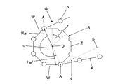
図1に、まずいくつかの概念を定義するために、ローラチェーンGとこれによって部分的に巻かれたチェーンホイールRとを概略的に図示する。ローラチェーンGは、互いに関節結合されるチェーン要素Kを有し、該チェーン要素Kは、回転ポイントPを介して互いに関節結合される。例示のチェーンホイールRは、8つの歯Zを有し、それらの間に歯間間隔が設けられ、該歯間間隔内に回転ポイントPが噛み合うことが可能である。2つの歯間または2つの歯間間隔間の角度ピッチτは、図示の例では、45°である。 FIG. 1 schematically shows a roller chain G and a chain wheel R partially wound thereby, in order to define some concepts first. The roller chain G has chain elements K that are articulated to each other, which chain elements K are articulated to each other via a rotation point P. The exemplary chain wheel R has eight teeth Z, an interdental space is provided between them, and the rotation point P can mesh within the interdental interval. In the illustrated example, the angular pitch τ between two teeth or between two teeth is 45 °.
さらにまた、図1において、チェーンホイールの下側に進入角φが示され、該進入角φは、たとえばローラチェーンGの方向を変えるべく案内されて生じる角度である。進入角φは、ローラチェーンGの実際の進行方向と、ローラチェーンGのチェーンホイールRからの分離ポイントAとチェーンホイールRの回転軸Dとの間の連結線に対する垂線Sとの間で測定される。進入角φは、図示の例では、約11°である。 Furthermore, in FIG. 1, an approach angle φ is shown on the lower side of the chain wheel, and the approach angle φ is an angle generated by being guided to change the direction of the roller chain G, for example. The approach angle φ is measured between the actual traveling direction of the roller chain G and the perpendicular S to the connecting line between the separation point A of the roller chain G from the chain wheel R and the rotation axis D of the chain wheel R. The The approach angle φ is about 11 ° in the illustrated example.
図1において、湾曲角υが示されるが、該湾曲角υは、ローラチェーンGのチェーンホイールRからの2つの分離ポイントA間の角度に対応し、図示の場合180°である。チェーンホイールRからチェーン要素Kが離れると、そのときの湾曲角υが急激に小さくなる。たとえば上下の異なる進入角φの場合、上側では、チェーン要素Kが離れ、しかしながら同時に下側では、最も近いチェーン要素Kはまだ上に載っていないからである。したがって、以下においては、最小の湾曲角以上であって、最大の湾曲角以下である中間の湾曲角υを出発点とする。 In FIG. 1, a bending angle υ is shown, which corresponds to the angle between the two separation points A from the chain wheel R of the roller chain G, which is 180 ° in the case shown. When the chain element K is separated from the chain wheel R, the bending angle υ at that time decreases rapidly. For example, in the case of different approach angles φ up and down, on the upper side, the chain element K is separated, but at the same time on the lower side, the closest chain element K is not yet placed on the top. Therefore, in the following, an intermediate bending angle υ that is not less than the minimum bending angle and not more than the maximum bending angle is set as a starting point.
さらにまた、チェーンホイールRの上側には、有効モーメントアームHeffが図示されているが、該モーメントアームHeffは、力、特にローラチェーンGの引張り力の作用線Wと、チェーンホイールRの回転軸Dとの間の垂直距離に対応する。瞬間湾曲角υと同様に、ローラチェーンの要素ごとの離間に基づき、特に、チェーンホイール回りのチェーンの多角形に基づき、ローラチェーンが動いている間有効モーメントアームHeffも変動する。チェーンホイールRの下側では、有効モーメントアームHeffは、幾分小さく、これは、ローラチェーンGの力の作用線Wが幾分傾斜しているために、有効モーメントアームHeff'は、もはや分離ポイントAを通過して進行しない。 Furthermore, an effective moment arm H eff is shown on the upper side of the chain wheel R. The moment arm H eff is a force, particularly an action line W of the pulling force of the roller chain G, and the rotation of the chain wheel R. Corresponds to the vertical distance from axis D. As with the instantaneous bend angle υ, the effective moment arm H eff also varies while the roller chain is moving, based on the separation of the elements of the roller chain, and in particular on the polygon of the chain around the chain wheel. Below the chain wheel R, the effective moment arm H eff is somewhat smaller, because the line of action W of the force of the roller chain G is somewhat inclined so that the effective moment arm H eff ′ is no longer Does not proceed past separation point A.
エスカレータまたは動く歩道の場合、通常、踏板またはパレットは、いわゆる踏板チェーンまたはパレットチェーンとして図示される搬送チェーンによって、両側に駆動され、かつこれらに固定される。 In the case of escalators or moving walkways, the treads or pallets are usually driven on and fixed to both sides by a transport chain, which is illustrated as a so-called treadle chain or pallet chain.
通常、搬送チェーンは3または4つの部分を有し、踏板毎に3または4つの要素を有している。用いられているチェーンホイールは、約16から25の歯を有している。いわゆる多角形効果を小さくするために、このように比較的高い数が選択される。 Typically, the transport chain has 3 or 4 parts, with 3 or 4 elements per tread. The chain wheel used has about 16 to 25 teeth. A relatively high number is thus selected in order to reduce the so-called polygonal effect.
多角形効果は、変動する有効モーメントアームHeffによって生じる(図1参照)。チェーンホイールは、通常、一定の角速度で駆動される。変動する有効モーメントアームによって、踏板チェーンの速度が変動し、移動する質量体(チェーン、軸、踏板)が連続して加速および減速することによって慣性力が生じ、かかる慣性力は、反対の力として、または回転モーメントとして、踏板チェーン/パレットチェーンに、または駆動部に導入され、そしてそれは一部短命化につながり、または特に駆動要素の設計に際して考慮すべき大きさでもありえる。特に、エスカレータの移動部分は、囲んでいるスチール構造体と共に、この、振動可能なばね−質量系を示す。特に、ここにおいて、チェーンはばねとして、踏板、軸(あれば)、ローラ、(踏板またはパレット上の)搬送される人、および再びチェーンは、質量体としてみなされる。このばね−質量系は、パラメータ次第で、チェーンホイールの歯数、走行速度および負荷に依存した非常に好ましくない動作点を有しうる。 The polygon effect is caused by a varying effective moment arm H eff (see FIG. 1). The chain wheel is usually driven at a constant angular velocity. The speed of the treadle chain fluctuates due to the fluctuating effective moment arm, and the inertial force is generated by continuously accelerating and decelerating the moving mass body (chain, shaft, treadle). , Or as a rotational moment, introduced into the tread chain / pallet chain or into the drive, which in part leads to a short life or may be of a size that should be taken into account especially when designing the drive element. In particular, the moving part of the escalator, along with the surrounding steel structure, shows this oscillating spring-mass system. In particular, here the chain is regarded as a spring, the tread, the shaft (if any), the roller, the person transported (on the tread or pallet) and again the chain as mass. Depending on the parameters, this spring-mass system can have a very unfavorable operating point depending on the number of teeth of the chain wheel, the running speed and the load.
実際のところ、一般には、チェーン部分を低減し歯数を増加させることによって、このようなことに出くわす。チェーン部分を低減し、歯数を増加させることによって、多角形効果が小さくなり、最終的には、多角形効果が実際のところ非常に小さく、したがってチェーン/踏板/プレートの移動が、多角形効果があるにせよ実際のところ妨害することはないほど均一となる。 In fact, this is generally encountered by reducing the chain portion and increasing the number of teeth. By reducing the chain part and increasing the number of teeth, the polygonal effect is reduced, and ultimately the polygonal effect is very small, so the movement of the chain / tread / plate will be In spite of this, it will be so uniform that it will not actually interfere.
また、チェーンホイール上へのチェーンの接線方向の進入に作用する案内部が、チェーンホイール領域内に設けられる。この手段の主たる目的は、チェーンホイール上にチェーンが進入するときの雑音を低下させることである。多角形効果もこの場合低下されるが、補償されていない。 In addition, a guide that acts on the tangential entry of the chain onto the chain wheel is provided in the chain wheel region. The main purpose of this measure is to reduce the noise when the chain enters on the chain wheel. The polygon effect is also reduced in this case, but is not compensated.
しかしながら、比較的小さいチェーン部分と比較的大きな数のチェーンホイールの歯とを有する従来の構成は、決定的な欠点を有している。 However, conventional arrangements having a relatively small chain portion and a relatively large number of chain wheel teeth have decisive drawbacks.
まず、踏板チェ−ン/パレットチェーンのコストが高いということがある。チェーン部分が多いほど、踏板あたり、またはメートルあたりの要素が増え、コストが上昇する。特に、摩耗を受ける部分の踏板/パレットあたりの数がより多くある。エスカレータの稼働時間については、踏板間および/またはパレット間の最大許容隙間をできる限り長く遵守することが非常に重要な基準である。 First, the cost of the tread chain / pallet chain is high. The more chain parts, the more elements per tread or per meter and the higher the cost. In particular, there are more parts per footboard / pallet that are subject to wear. It is a very important criterion for the operating time of escalators to observe as long as possible the maximum permissible gap between treads and / or pallets.
チェーンホイールの歯数が多いことによって、結果として、比較的大きな直径となり、特に駆動ステーションのために構成スペースが必要になる。したがって、建物内が、コストのかかる空間に占領されることになる。大きな直径が必要である結果として、高い駆動モーメントが必要となり、駆動のための相応のコストをもたらすことになる。 The large number of teeth on the chain wheel results in a relatively large diameter and requires a construction space, especially for the drive station. Therefore, the interior of the building is occupied by a costly space. As a result of the need for a large diameter, a high driving moment is required, resulting in a corresponding cost for driving.
冒頭で述べたタイプのエスカレータは、欧州特許出願公開第1344740号明細書から知られている。そこに記載されたエスカレータは、回りに部分的にローラチェーンが巻かれる、上部車間にわたって多角形補償して駆動されるチェーンホイールを有している。このチェーンホイールは、奇数の歯を有している。歯数を奇数とすることによって、上部車間は多角形補償ではなく、反対に極度に不均一に進行する。上部車間には、たとえば、チェーン、ローラ、軸および踏板またはプレートなどの質量体が設けられるので、この不均一性から、上部車間の踏板またはプレート上に負荷される力が生じる。この種のエスカレータは、下部車間における質量体に対する上部車間における質量体間の比率が大きいために、高い負荷がかかった状態では、比較的ゆっくりと走行する。負荷がかかっていない状態、または乗っている人が少しの状態では、上部車間においても非常に静かでない走行となる。 An escalator of the type mentioned at the outset is known from EP 1344740. The escalator described therein has a chain wheel which is driven with polygonal compensation between upper cars, in which a roller chain is partially wound around. This chain wheel has an odd number of teeth. By making the number of teeth an odd number, the distance between the upper cars is not polygonal compensation, but on the contrary, it proceeds extremely unevenly. Since mass bodies such as chains, rollers, shafts, and treads or plates are provided between the upper cars, for example, a force applied on the treads or plates between the upper cars is generated from this non-uniformity. Since this type of escalator has a large ratio between the mass bodies between the upper cars and the mass bodies between the lower cars, the escalator travels relatively slowly under a high load. When there is no load or a small number of people are on the road, the driving is not very quiet even between the upper cars.
本発明が基礎とする課題は、冒頭で述べたタイプの装置であって、少なくとも1つのチェーンホイールの歯数が比較的少なくとも、比較的静かに走行する装置を提供することである。 The problem on which the present invention is based is to provide a device of the type mentioned at the outset, in which the number of teeth of at least one chain wheel is relatively at least relatively quiet.
このことは、本発明に従えば、請求項1の特徴を有する冒頭で述べたタイプのエスカレータによって達成される。下位の請求項は、本発明の好ましい実施形態に関連する。
This is achieved according to the invention by an escalator of the type mentioned at the outset having the features of
上部車間における少なくとも1つのチェーンホイールのチェーンの有効モーメントアームは、下部車間における少なくとも1つのチェーンホイールのチェーンの有効モーメントアームと同じであるように構成されてなる。この結果、たとえば上部車間に指定された多角形補償の場合、上部車間が一定の速度で走行するだけでなく、下部車間も一定の速度で走行するようになる。本発明に従った手段によって、実質的に大きな部分を有する、たとえばチェーン部分を有する踏板チェーンおよび/またはパレットチェーンについてを、半分の大きさの踏板部分またはチェーン部分とすること、および/または必要な空間を小さくすることを可能とする。 The effective moment arm of the chain of the at least one chain wheel between the upper cars is configured to be the same as the effective moment arm of the chain of the at least one chain wheel between the lower cars. As a result, for example, in the case of polygon compensation designated between the upper cars, not only the upper cars travel at a constant speed, but also the lower cars travel at a constant speed. By means according to the invention, for a tread chain and / or pallet chain with a substantially large part, for example with a chain part, a half-size tread part or chain part and / or necessary It is possible to reduce the space.
また、第1のチェーンホイールおよび第2のチェーンホイールは、第1のチェーンホイールでの最小有効モーメントアームにおいて、同じ車間内で、第2のチェーンホイールでの有効モーメントアームは最小とはならないように、好ましくは、多くとも、最大値と最小値との間の差の±20%だけ最大値から異なるように、特に最大となるように、互いに動作されて設けられる。そのために、たとえば、第1のチェーンホイールの第2のチェーンホイールとの角度位置は、少なくとも、角度ピッチの±30%、好ましくは±40%、特に角度ピッチの半分だけ異ならせてもよい。2つのチェーンホイールをこのように逆位相とすることによって、たとえば、回転方向転換ホイールとして実施された第2のチェーンホイールの揺動が小さくなる。 In addition, the first chain wheel and the second chain wheel are configured so that the effective moment arm in the second chain wheel is not minimized in the same distance between the same effective distances in the minimum effective moment arm in the first chain wheel. Preferably, they are arranged to be operated in relation to one another so that at most they differ from the maximum value by ± 20% of the difference between the maximum value and the minimum value. To that end, for example, the angular position of the first chain wheel with respect to the second chain wheel may differ at least by ± 30% of the angular pitch, preferably by ± 40%, in particular by half the angular pitch. By setting the two chain wheels in opposite phases in this way, for example, the swing of the second chain wheel implemented as a rotation direction changing wheel is reduced.
さらに、エスカレータは少なくとも1つの案内部を有し、該案内部は、第1のチェーンホイールおよび/または第2のチェーンホイールへのチェーンの進入角に影響することが可能であって、該少なくとも1つの案内部は、有効モーメントアームが最小の場合の進入角が、有効モーメントアームが最大の場合よりも小さくなるように設けられる。案内部をこのように設けることによって、エスカレータが走行している場合、モーメントアームの振動運動をおおよそ零とすることができ、走行の静粛性に関しては、プラスに働く。特に、少なくとも1つの案内部をこのように設けた場合、案内ローラにかかる負荷は非常にわずかになる。コストの面においても比較的有利な案内ローラの利用が可能となる。 Furthermore, the escalator has at least one guide, which can influence the angle of entry of the chain into the first chain wheel and / or the second chain wheel, the at least one guide The two guide portions are provided such that the approach angle when the effective moment arm is minimum is smaller than that when the effective moment arm is maximum. By providing the guide portion in this manner, when the escalator is traveling, the vibration motion of the moment arm can be made substantially zero, and the quietness of traveling works positively. In particular, when at least one guide portion is provided in this way, the load on the guide roller is very small. A relatively advantageous guide roller can be used in terms of cost.
本発明の特徴と利点が、添付の図を参照した、好ましい実施形態の以下の説明によって明らかになる。
図2に示すエスカレータは、ローラチェーンとして実施されるチェーン1を有し、該チェーン1は、第1の動力チェーンホイール2と、リバースホイールとして働く第2のチェーンホイール3との周りを回転する。各チェーンホイール2,3は、6つの、概略的に図示された歯を有する。チェーン1とエスカレータの踏板またはパレット(図示せず)が結合される。図2および図3においては、回転するハンドレールだけが示されるが、該ハンドレールは、エスカレータが動いている間利用者が握ることができる。チェーン1は、チェーンホイール2,3間において、図2〜図4の上部の上部車間5と、図2〜図4の下部の下部車間6を形成する。
The escalator shown in FIG. 2 has a
第1のチェーンホイール2は、駆動モータ7によって駆動チェーン8を介して、多角形効果または多角形補償を受けずに駆動される。これは、たとえば、図示された実施形態においては、駆動チェーン8内に食い込む非円形ホイール9によって達成することが可能である。多角形補償駆動のさらなる可能性は、国際公開第03/036/129号明細書から知られ、該公開公報の一部に説明されている。多角形補償駆動によって、第1のチェーンホイール2を、変動する角速度で駆動することが可能となり、従動チェーン1が一定またはほぼ一定の速度で走行することを可能とする。
The
ハンドレール4は、駆動モータ7によって駆動され、ハンドレール4は、一定の角速度で駆動される。第2のチェーンホイール3は可動固定要素10を介して移動可能に支持される。
The handrail 4 is driven by a
図4に示されるチェーン1は、短く描かれている。図4は、第1のチェーンホイール2に対する第2のチェーンホイール3は、角度位置については、ずらされている。たとえば、チェーン1の乗載ポイント11を通過する半径線12は、第1のチェーンホイール2における図4の水平線13と角度αをなし、これは約60°である。それに対して、チェーン1の対応する乗載ポイント14を通過する半径線15は、第2のチェーンホイール3において図4の水平線13と角度βをなし、この角はおよそ30°である。チェーンホイール2,3の角度位置は30°ずつ異なり、これは、チェーンホイール2,3の6つの歯の角度ピッチの半分に相当する。角度ピッチは360°を歯数で割った値であるからである。
The
チェーンホイール2,3の角度位置のこのような違いによって、第1のチェーンホイール2において、チェーン1が最小有効モーメントアーム16,16’によって捕捉されるとき、第2のチェーンホイール3におけるチェーン1は最大有効モーメントアーム17,17’で捕捉されることになる(図4参照)。反対に、第1のチェーンホイール2において、チェーン1が最大有効モーメントアームで捕捉されるときには、第2のチェーンホイール3において、チェーン1は、最小有効モーメントアームで捕捉されることになる(図示せず)。
Due to this difference in the angular position of the
さらにまた、図4から明らかなように、第1のチェーンホイール2において、上部車間5における有効モーメントアーム16は、下部車間6における有効モーメントアーム16’と同じである。さらにまた、図から明らかなように、第2のチェーンホイール3では、上部車間5における有効モーメントアーム17は、下部車間6における有効モーメントアーム17’と同じである。
Furthermore, as apparent from FIG. 4, in the
図4に、チェーン1のチェーンホイールへの進入角φ1,φ2を定めることが可能である案内部18,19が示されている。この場合、特に、案内部18は図4においてはなるべく下に、または案内部19は、図4においてなるべく上に設けられ、最小有効モーメントアーム16,16’の場合の進入角φ1(図4の第1のチェーンホイール2参照)は、最大有効モーメントアーム17,17’の場合の進入角φ2(図4の第2のチェーンホイール3参照)よりも明らかに小さい。
FIG. 4 shows guide
図3に従った実施形態の場合、第2のチェーンホイール3に代わってリバース湾曲部20が設けられる。このリバース湾曲部20の場合、その半径は、リバース湾曲部20においても、上部車間5における有効モーメントアーム(図示せず)と下部車間6における有効モーメントアームが同じになるように選択される。さらにまた、図3に従った実施形態においても、案内部18,19は、チェーン1をリバース湾曲部に、最小有効モーメントアームの場合の進入角が、最大有効モーメントアームの場合の進入角よりも小さくなるように導く。さらにまた、リバース湾曲部20、第1のチェーンホイール2、およびチェーン1は、第1のチェーンホイール2ではチェーン1が最小有効モーメントアーム16,16’で捕捉されるときは、リバース湾曲部20におけるチェーン1は最大有効モーメントアームで捕捉されるように、またその逆となるように配置される。
In the case of the embodiment according to FIG. 3, a
これらの実施形態のさらなる機能についての以下に説明する。
用いられているチェーンホイール2,3の歯数は、偶数である。これは、チェーン1の湾曲角が180°になる場合であって、正常な場合のエスカレータ/動く歩道の場合である。決定的なのは、上部車間側での有効モーメントアームは、常に実質的には、下部車間側での有効モーメントアームと同じであるということである。この結果、上部車間に指定される多角形補償の場合、上部車間が一定の速度で走行するだけでなく、下部車間もそうである(180°の湾曲角の場合の奇数の歯においては、下部車間は、従来の多角形補償ではない駆動のおよそ2倍の不均一性で走行する)。
Further functions of these embodiments are described below.
The number of teeth of the
湾曲角は、有効モーメントアームが、上部車間と下部車間とで同じである場合には、180°偏向させて実施してもよい。つまり、これらの場合の歯数と湾曲角とは、合わせる必要がある。この条件に注意すれば、上部車間および下部車間において、静かなエスカレータ/動く歩道の走行にとって必須である、均一なチェーン速度が達成される。 When the effective moment arm is the same between the upper vehicle and the lower vehicle, the bending angle may be deflected by 180 °. That is, it is necessary to match the number of teeth and the bending angle in these cases. By paying attention to this condition, a uniform chain speed is achieved between the upper and lower cars, which is essential for quiet escalator / moving sidewalk travel.
従動チェーンホイール2の場合と同様な法則性が、従動されないリバースステーション(エスカレータの場合は通常は下部の地上ステーション)にも当てはまる。同一の有効モーメントアームであることに注意することがこの場合も重要である。このことは、逆転(リバース)のためにチェーンホイール3が適用されるのではなく、歯が切られていない、固定されて取り付けられた、またはばねおよび/または弾性的に取り付けられたリバース湾曲部20が適用される場合にも当てはまる。すなわち、リバース湾曲部の半径または直径は、チェーン1の方向転換手段ポイントは、対応する歯数を有するチェーンホイールのそれに対応する、対応の円弧上にあるように設定する。
The same principle as in the case of the driven
チェーンホイール2,3は、一定でない角速度で走行し、この効果は、歯数が少なくなるほど大きくなるので、このようなことはできる限り軽く、また、わずかの慣性モーメントで実施して、そこからチェーン/踏板/パレットに及ぼされる妨害力ができるだけ小さくなるように注意することが必要である。特に、回転ポイントからさらに離れて位置するポイントにおける重量の最適化に注意することが必要であり、場合によっては、適切な軽量化−スペースなどの余裕を残すなどの措置が講じられる。
The
チェーンホイール2,3への特に大きな構成のチェーン1の多角形適合によって、通常、噛合いから次の噛合いまでの、チェーンホイール2,3間の軸間距離は変動する。チェーン1は、弾性伸びを別とすれば、常に一定の長さを有している。駆動装置−チェーンホイールは、通常、目的の場所に固定して取り付けられ、リバース部−チェーンホイールは固定部10にばね弾性によって、および線形運動可能に取り付けられる。これが大きくなればなるほどチェーン部分は大きくなり、チェーンホイール−歯数は小さくなる。
Due to the polygonal fit of the
比較的チェーン部分が小さく、歯数が比較的多い従来のエスカレータの場合、このようなことは反対に注意する必要がない。 In the case of a conventional escalator having a relatively small chain portion and a relatively large number of teeth, this need not be noted.
本発明に従ったエスカレータ(または動く歩道)の場合、チェーン部分は非常に大きくすることができるので、すなわち、踏板部分/パレット部分の1/1または1/2、および歯数は非常に小さく、すなわち6または4までとすることができるので、リバースホイールとして働く第2のチェーンホイール3の、またはリバース湾曲部20の線形運動を、エスカレータ/動く歩道の走行の静粛性にとって妨害となる要素となるほど、大きくすることが可能である。リバースステーションのこのような大きな線形運動から、妨害となる慣性力が生じ、これがノイズを発生させる。特に、好ましくないのは、駆動ホイールおよびリバースチェーンホイールが、同じ(たとえば、水平に対する、チェーンホイールエッジの角αまたはβによって測定される)湾曲角を有している場合の位置関係である。
For escalators (or moving walkways) according to the invention, the chain part can be very large,
したがって、チェーンホイール2,3の相対角α,βに注意が必要であり、すなわち、これらは逆位相でなければならない。第1のチェーンホイール2の角と第2のチェーンホイール3の角との間には、およそ半分の角度ピッチ(±20%)がなければならない(角度ピッチ=360°/歯数)。すなわち、チェーンの軸間距離、巻き上げ高さ、および長さは、互いに一致させねばならない。
Therefore, attention must be paid to the relative angles α and β of the
さらにまた、第1および第2のチェーンホイール2,3は、できる限り同じ歯数を有するべきである。同じ歯数から±30%の範囲の偏差は許容される。
Furthermore, the first and
さらにまた、チェーンの案内が重要である。本発明に従ったエスカレータの実施形態において適用される案内部18,19は、最小有効モーメントアームの少し上でチェーンホイール2,3上へのチェーン1の進入を生じさせる。さらにまた、その端部での湾曲は任意であり、端部での湾曲によって、チェーン1には、チェーンホイール2,3上に来る少し前に、またはチェーンホイール2,3から案内部に移った後に、半径方向に速度成分が生じることになる。チェーンホイールの歯間間隔への、または案内部上へのチェーンリバースポイントの衝突成分も、明らかに小さくなり、これによって、ノイズが実質的に少なくなり、好ましい走行特性が得られる。
Furthermore, the guidance of the chain is important. The
チェーンホイール上へのチェーンの接線方向における進入をもたらし、したがって進入ノイズ(チェーン−チェーンホイール)を低下させる、チェーン案内部は、本発明に従ったエスカレータの場合、適用することができない。ここで実現されるチェーンホイールの歯数がわずかの場合には、そしてそこから生じる角度比の場合には、ローラに対する負荷があまりにも大きくなる、またはこれらの負荷に対するローラの大きさを定めなければならないからであり、これらのことはコストを増加させる。特に、案内部をこのように設ける場合には、リバースステーションの大きな振動をもたらし、上述のようにそれ相応の短所をもたらす。 A chain guide that results in a tangential entry of the chain onto the chain wheel and thus reduces the entry noise (chain-chain wheel) is not applicable in the case of an escalator according to the invention. If the number of teeth of the chain wheel realized here is small, and in the case of the resulting angle ratio, the load on the roller will be too great or the size of the roller for these loads must be defined. This is because they must increase costs. In particular, when the guide portion is provided in this manner, it causes a large vibration of the reverse station, and the corresponding disadvantages as described above.
本発明に従ったエスカレータの場合、最小有効モーメントアームと最大有効モーメントアーム間の案内部の垂直高さは、最小モーメントアーム近くにある。案内部を垂直高さ内に設ければ、エスカレータ装置の走行中、リバースステーションの振動運動が、およそ零となり、この結果、走行の静粛性にプラスに作用する。特に、案内部をこのように設ける場合、ローラには、非常にわずかの負荷がかかるだけである。コスト面においても比較的好ましいローラを利用することが可能である。 In the case of the escalator according to the invention, the vertical height of the guide between the minimum effective moment arm and the maximum effective moment arm is close to the minimum moment arm. If the guide portion is provided within the vertical height, the vibration motion of the reverse station becomes approximately zero during the travel of the escalator device, and as a result, it positively affects the quietness of the travel. In particular, when the guide portion is provided in this way, the roller is subjected to a very slight load. It is possible to use a relatively preferable roller in terms of cost.
チェーン案内部の最適高さは、以下のように算出される。チェーン要素は、案内部18,19を離れるとき、一定の角度だけ折れる。そこで、斜辺がここで問題となっているチェーン要素であり、直角を挟む辺の1つが水平である、小さな直角三角形を描くことができる、または想像する。三角関数を用いて、すべての長さを計算する。ここで、水平な辺の合計を求める。これを、角度ピッチ内のチェーンホイールの各角度位置毎に求める。再び、チェーンがさらにわずかに走行し、チェーンホイールが角度ピッチ分までさらに回転することを想像する。たとえば60°の角度ピッチは、たとえば3°ずつ20のステップに分けられる。そこで、案内部の高さは、各角度ピッチ毎の水平な辺の合計ができる限り一定値をもたらすまで変えられる。そこで、この変動が最小値に達した場合、リバースチェーンホイール/リバースステーションの線形運動も最小となる。
The optimum height of the chain guide is calculated as follows. When the chain element leaves the
実際のエスカレータでは、場合によっては、チェーン案内部をチェーンが通過する場合、移行部分において水平/立上り部分(リバース半径)が生じる多角形の影響をまだ考慮すべきであるかもしれない。
本発明は、次の実施形態が可能である。
(1)複数の踏板またはパレットと、
踏板またはパレットを駆動するための少なくとも1つのチェーン1と、
チェーン1が部分的に回転する少なくとも1つのチェーンホイール2,3であって、チェーン1がチェーンホイール2,3に基づいて上部車間5および下部車間6を形成する、チェーンホイール2,3と、
少なくとも1つのチェーンホイール2,3の運動の多角形補償のための手段と、を含むエスカレータにおいて、
上部車間5での少なくとも1つのチェーンホイール2,3におけるチェーン1の有効モーメントアーム16,17は、下部車間6での少なくとも1つのチェーンホイール2,3におけるチェーン1の有効モーメントアーム16’,17’と実質的に同じであることを特徴とするエスカレータ。
(2)エスカレータは、チェーン1が部分的に回転する第2のチェーンホイール3を有し、第1のチェーンホイール2および第2のチェーンホイール3は、第1のチェーンホイール2での最小有効モーメントアーム16,16’において、同じ車間5,6内で、第2のチェーンホイール3での有効モーメントアーム17,17’は最小とはならないように、好ましくは、多くとも、最大値と最小値との間の差の±20%だけ最大値から異なるように、特に最大となるように、互いに動作されて設けられることを特徴とするエスカレータ。
(3)エスカレータは、少なくとも1つの案内部18,19を有し、該案内部は、第1および/または第2のチェーンホイール2,3へのチェーン1の進入角φ1,φ2に影響することが可能であって、該少なくとも1つの案内部18,19は、有効モーメントアーム16,16’が最小の場合の進入角φ1,φ2が、有効モーメントアーム17,17’が最大の場合よりも小さくなるように設けられることを特徴とするエスカレータ。
(4)第1のチェーンホイール2は動力チェーンホイールであることを特徴とするエスカレータ。
(5)第2のチェーンホイール3はリバースホイールであることを特徴とするエスカレータ。
(6)第1および/または第2のチェーンホイール2,3の歯数は偶数であることを特徴とするエスカレータ。
(7)第1のチェーンホイール2の歯数は、12以下、特に4または6であることを特徴とするエスカレータ。
(8)第2のチェーンホイール3の歯数は、12以下、特に4または6であることを特徴とするエスカレータ。
(9)第1のチェーンホイール2の歯数は、第2のチェーンホイール3の歯数と異なる、または略等しい、もしくは等しいことを特徴とするエスカレータ。
(10)第1および/または第2のチェーンホイール2,3の中間湾曲角υは、角度ピッチτの整数倍から多くとも角度ピッチτの±20%だけ異なることを特徴とするエスカレータ。
(11)第1および/または第2のチェーンホイール2,3の中間湾曲角υは、角度ピッチτの整数倍であることを特徴とするエスカレータ。
(12)第1のチェーンホイール2の角度位置は、第2のチェーンホイール3の角度位置から少なくとも角度ピッチτの±30%だけ異なることを特徴とするエスカレータ。
(13)第1のチェーンホイール2の角度位置は、第2のチェーンホイール3の角度位置から少なくとも角度ピッチτの±40%、特に角度ピッチτの半分だけ異なることを特徴とするエスカレータ。
(14)エスカレータは、リバースホイールとしての第2のチェーンホイール3に代えて、リバース湾曲部20を有することを特徴とするエスカレータ。
(15)リバース湾曲部20の中間湾曲角υは、角度ピッチτの整数倍から多くとも角度ピッチτの±20%だけ異なることを特徴とするエスカレータ。
(16)リバース湾曲部20の中間湾曲角υは、角度ピッチτの整数倍であることを特徴とするエスカレータ。
In an actual escalator, in some cases, when the chain passes through the chain guide, it may still be necessary to consider the effect of the polygon that results in a horizontal / rising part (reverse radius) at the transition part.
The following embodiments are possible for the present invention.
(1) a plurality of treads or pallets;
At least one
Means for compensating for polygons of movement of at least one
The
(2) The escalator has a
(3) The escalator has at least one
(4) The escalator, wherein the
(5) The escalator, wherein the
(6) An escalator characterized in that the number of teeth of the first and / or
(7) The escalator characterized in that the number of teeth of the
(8) An escalator characterized in that the number of teeth of the
(9) An escalator characterized in that the number of teeth of the
(10) The escalator characterized in that the intermediate bending angle υ of the first and / or
(11) The escalator characterized in that the intermediate bending angle υ of the first and / or
(12) The escalator characterized in that the angular position of the
(13) The escalator characterized in that the angular position of the
(14) The escalator has a
(15) The escalator characterized in that the intermediate bending angle υ of the
(16) The escalator characterized in that the intermediate bending angle υ of the
Claims (19)
踏板またはパレットを駆動するための少なくとも1つのチェーン(1)と、
チェーン(1)が部分的に巻付く少なくとも1つのチェーンホイール(2,3)であって、チェーン(1)がチェーンホイール(2,3)から延びる上部車間(5)および下部車間(6)を形成する、チェーンホイール(2,3)と、
チェーン(1)の上部車間(5)を案内する第1案内部(18)と、
チェーン(1)の下部車間(6)を案内する第2案内部(19)と、
少なくとも1つのチェーンホイール(2,3)の運動の多角形補償のための手段と、を含むエスカレータにおいて、
上部車間(5)での少なくとも1つのチェーンホイール(2,3)におけるチェーン(1)の有効モーメントアーム(16,17)は、下部車間(6)での少なくとも1つのチェーンホイール(2,3)におけるチェーン(1)の有効モーメントアーム(16’,17’)と同じであり、
チェーン(1)は、チェーンホイール(2,3)に進入するチェーン(1)の角度(φ1,φ2)がチェーンホイール(2,3)から出るチェーン(1)の角度(φ1,φ2)に等しく、有効モーメントアーム(16,16’)が最小の場合のチェーン(1)の角度(φ1)が、有効モーメントアーム(17,17’)が最大の場合のチェーン(1)の角度(φ2)よりも小さくなるように、第1および第2案内部(18,19)によって案内されることを特徴とするエスカレータ。 With multiple treads or pallets,
At least one chain (1) for driving treads or pallets;
At least one chain wheel (2, 3) around which the chain (1) is partially wound, wherein the chain (1) extends between the upper wheel (5) and the lower wheel (6) extending from the chain wheel (2, 3). Forming a chain wheel (2, 3);
A first guide portion (18) for guiding the upper space (5) of the chain (1);
A second guide part (19) for guiding the lower space (6) of the chain (1);
Means for compensating for polygons of movement of at least one chain wheel (2, 3),
The effective moment arm (16, 17) of the chain (1) in the at least one chain wheel (2, 3) in the upper inter-vehicle (5) is at least one chain wheel (2, 3) in the lower inter-vehicle (6). Is the same as the effective moment arm (16 ′, 17 ′) of the chain (1) at
Chain (1), the angle (phi 1, phi 2) of the chain (1) which enters the chain wheel (2, 3) the angle of the chain (1) out from the chain wheel (2, 3) (phi 1, phi 2 ), the angle (φ 1 ) of the chain (1) when the effective moment arm (16, 16 ′) is the smallest, the angle (φ 1 ) of the chain ( 1 ) when the effective moment arm (17, 17 ′) is the largest. An escalator characterized by being guided by the first and second guide portions (18, 19) so as to be smaller than the angle (φ 2 ).
Applications Claiming Priority (4)
| Application Number | Priority Date | Filing Date | Title |
|---|---|---|---|
| DE102006036353A DE102006036353A1 (en) | 2006-08-02 | 2006-08-02 | Escalator, has steps driven by chain conveyor, which is driven by driving wheel, where driving wheel is driven in polygon-offset manner to drive driving wheel with non-constant angular speed and conveyor is operated with constant speed |
| DE102006036353.1 | 2006-08-02 | ||
| DE102007034628 | 2007-07-23 | ||
| DE102007034628.1 | 2007-07-23 |
Related Parent Applications (1)
| Application Number | Title | Priority Date | Filing Date |
|---|---|---|---|
| JP2012234934A Division JP2013063854A (en) | 2006-08-02 | 2012-10-24 | Escalator |
Publications (2)
| Publication Number | Publication Date |
|---|---|
| JP2016027993A JP2016027993A (en) | 2016-02-25 |
| JP5996757B2 true JP5996757B2 (en) | 2016-09-21 |
Family
ID=38996898
Family Applications (3)
| Application Number | Title | Priority Date | Filing Date |
|---|---|---|---|
| JP2009522151A Expired - Fee Related JP5461182B2 (en) | 2006-08-02 | 2007-07-27 | Escalator |
| JP2012234934A Pending JP2013063854A (en) | 2006-08-02 | 2012-10-24 | Escalator |
| JP2015205097A Expired - Fee Related JP5996757B2 (en) | 2006-08-02 | 2015-10-16 | Escalator |
Family Applications Before (2)
| Application Number | Title | Priority Date | Filing Date |
|---|---|---|---|
| JP2009522151A Expired - Fee Related JP5461182B2 (en) | 2006-08-02 | 2007-07-27 | Escalator |
| JP2012234934A Pending JP2013063854A (en) | 2006-08-02 | 2012-10-24 | Escalator |
Country Status (8)
| Country | Link |
|---|---|
| US (3) | US8286778B2 (en) |
| EP (3) | EP2049428B1 (en) |
| JP (3) | JP5461182B2 (en) |
| CN (1) | CN102249141B (en) |
| ES (1) | ES2402824T3 (en) |
| PL (1) | PL2049428T3 (en) |
| RU (1) | RU2412896C2 (en) |
| WO (1) | WO2008014938A1 (en) |
Families Citing this family (16)
| Publication number | Priority date | Publication date | Assignee | Title |
|---|---|---|---|---|
| FI20090265A (en) * | 2009-07-03 | 2011-01-04 | Kone Corp | Passenger conveyor and method |
| US8925689B2 (en) | 2011-01-19 | 2015-01-06 | Smart Lifts, Llc | System having a plurality of elevator cabs and counterweights that move independently in different sections of a hoistway |
| US9365392B2 (en) | 2011-01-19 | 2016-06-14 | Smart Lifts, Llc | System having multiple cabs in an elevator shaft and control method thereof |
| US8430210B2 (en) | 2011-01-19 | 2013-04-30 | Smart Lifts, Llc | System having multiple cabs in an elevator shaft |
| CN103582605B (en) | 2011-05-23 | 2017-04-05 | 奥的斯电梯公司 | The method of the polygon effect in polygon compensation system of connections, passenger conveyor system and reduction chain drive system |
| WO2013092238A1 (en) | 2011-12-22 | 2013-06-27 | Ketten-Wulf Betriebs-Gmbh | Traction mechanism drive |
| TWI612241B (en) * | 2012-12-07 | 2018-01-21 | 伊文修股份有限公司 | Escalator with a step belt, and moving walkway with a plate belt |
| DE102013103323A1 (en) | 2013-04-03 | 2014-10-23 | Ketten-Wulf Betriebs-Gmbh | traction drive |
| DE102014103045A1 (en) | 2014-03-07 | 2015-09-10 | Ketten-Wulf Betriebs-Gmbh | Ride, especially roller coaster |
| RU2682693C1 (en) * | 2014-05-28 | 2019-03-20 | Инвенцио Аг | Artificial chain of walkway or escalator |
| US10214389B2 (en) | 2014-12-02 | 2019-02-26 | Otis Elevator Company | Drive chain and drive chain mechanism and conveyor comprising such a drive chain mechanism |
| CN104843424A (en) * | 2015-05-20 | 2015-08-19 | 江苏比微曼智能科技有限公司 | Workpiece fitting mechanism and chain type conveying mechanism used for same |
| EP3243788B1 (en) | 2016-05-10 | 2020-03-04 | Otis Elevator Company | Passenger conveyor |
| CN105730711B (en) * | 2016-05-11 | 2017-11-24 | 亳州沃野知识产权服务有限公司 | A kind of aircraft automatic elevator |
| JP6382425B1 (en) * | 2017-10-13 | 2018-08-29 | 三菱重工機械システム株式会社 | Vertical circulation parking device and method for remodeling the same |
| CN112499450B (en) * | 2020-11-27 | 2022-12-06 | 中铁第四勘察设计院集团有限公司 | System and method for monitoring stability of main drive motor of escalator |
Family Cites Families (28)
| Publication number | Priority date | Publication date | Assignee | Title |
|---|---|---|---|---|
| US1956714A (en) * | 1932-07-29 | 1934-05-01 | Otis Elevator Co | Mechanical transmission system |
| US3419127A (en) * | 1966-07-11 | 1968-12-31 | Otis Elevator Co | Tension carriage for passenger conveyors |
| USRE27439E (en) * | 1970-09-25 | 1972-07-18 | Inclined moving walkway arrangement | |
| US3677388A (en) * | 1970-11-23 | 1972-07-18 | Westinghouse Electric Corp | Modular drive unit for a conveyor |
| US3734263A (en) * | 1971-07-02 | 1973-05-22 | A Dirks | Revolvable station for processing a movable procession of factory-work pieces such as animal carcasses |
| US4082173A (en) * | 1976-06-10 | 1978-04-04 | Otis Elevator Company | Drive unit for an endless conveyor |
| US4498890A (en) * | 1982-12-20 | 1985-02-12 | General Electric Company | Fixed track chain drive |
| JPH03297792A (en) * | 1990-04-18 | 1991-12-27 | Hitachi Ltd | Power transmission device, sprocket used for the device, and passenger conveyor |
| DE19849235B4 (en) | 1998-10-26 | 2004-12-02 | Jungheinrich Ag | Device for actuating and controlling an electric steering motor system |
| US6427823B1 (en) * | 1999-04-15 | 2002-08-06 | Kabushiki Kaisha Toshiba | Conveyor device |
| JP2002114472A (en) * | 2000-10-04 | 2002-04-16 | Hitachi Ltd | Passenger conveyor and driving device |
| JP4683704B2 (en) * | 2000-10-23 | 2011-05-18 | 東芝エレベータ株式会社 | Passenger conveyor equipment |
| WO2002088015A1 (en) * | 2001-04-27 | 2002-11-07 | Kone Corporation | Method and device for reducing the polygon effects in an area of deviation in passenger conveyor systems |
| US7296671B2 (en) * | 2000-12-21 | 2007-11-20 | Kone Corporation | Drive system for escalators or moving walkways |
| DE10063844B4 (en) * | 2000-12-21 | 2004-07-22 | Kone Corp. | Drive system for escalators and moving walks |
| DE10138462B4 (en) * | 2001-08-04 | 2004-09-30 | Kone Corp. | Method for guiding link chains in the area of deflection devices of a passenger conveyor system |
| DK1440255T3 (en) * | 2001-10-26 | 2010-08-16 | Ketten Wulf Betriebs Gmbh | Joint chain drive and method of operating the chain drive wheel of a link chain |
| US6540060B1 (en) * | 2001-10-30 | 2003-04-01 | Otis Elevator Company | Belt drive assembly for a passenger conveyor |
| JP4107852B2 (en) * | 2002-02-28 | 2008-06-25 | 東芝エレベータ株式会社 | Conveyor device |
| DE20204029U1 (en) | 2002-03-13 | 2002-05-29 | Thyssen Fahrtreppen Gmbh | Escalator or moving walk |
| CN100457597C (en) * | 2002-04-25 | 2009-02-04 | 通力股份公司 | Drive system for reducing the polygon effect in continuous drive chains of escalators and moving walkways |
| DE10218374A1 (en) | 2002-04-25 | 2003-11-13 | Kone Corp | Drive system for escalators and moving walkways comprises a drive motor, a drive chain, deviating elements, and a device for changing the speed of the drive chain and its components in the vicinity of the deviating elements |
| JP4458770B2 (en) * | 2002-11-25 | 2010-04-28 | 東芝エレベータ株式会社 | Conveyor device |
| US20060011450A1 (en) * | 2003-01-07 | 2006-01-19 | Fargo Richard N | Drive belt for a passenger conveyor |
| JP4304136B2 (en) * | 2004-03-23 | 2009-07-29 | 東芝エレベータ株式会社 | Conveyor device |
| JP2006193237A (en) * | 2005-01-11 | 2006-07-27 | Toshiba Elevator Co Ltd | Man conveyor |
| JP5176223B2 (en) * | 2006-07-04 | 2013-04-03 | インベンテイオ・アクテイエンゲゼルシヤフト | Driving system for passenger transport equipment |
| JP5126880B2 (en) * | 2006-08-31 | 2013-01-23 | 東芝エレベータ株式会社 | Conveyor device |
-
2007
- 2007-07-27 CN CN2011101550486A patent/CN102249141B/en not_active Expired - Fee Related
- 2007-07-27 ES ES07786388T patent/ES2402824T3/en active Active
- 2007-07-27 PL PL07786388T patent/PL2049428T3/en unknown
- 2007-07-27 EP EP07786388A patent/EP2049428B1/en not_active Not-in-force
- 2007-07-27 RU RU2009107222/11A patent/RU2412896C2/en not_active IP Right Cessation
- 2007-07-27 EP EP12162123A patent/EP2471737A1/en not_active Withdrawn
- 2007-07-27 JP JP2009522151A patent/JP5461182B2/en not_active Expired - Fee Related
- 2007-07-27 WO PCT/EP2007/006676 patent/WO2008014938A1/en active Application Filing
- 2007-07-27 US US12/376,018 patent/US8286778B2/en not_active Expired - Fee Related
- 2007-07-27 EP EP12162122A patent/EP2471736A1/en not_active Withdrawn
-
2011
- 2011-05-26 US US13/116,070 patent/US8292058B2/en not_active Expired - Fee Related
- 2011-05-26 US US13/116,075 patent/US8292059B2/en not_active Expired - Fee Related
-
2012
- 2012-10-24 JP JP2012234934A patent/JP2013063854A/en active Pending
-
2015
- 2015-10-16 JP JP2015205097A patent/JP5996757B2/en not_active Expired - Fee Related
Also Published As
| Publication number | Publication date |
|---|---|
| JP2013063854A (en) | 2013-04-11 |
| US8286778B2 (en) | 2012-10-16 |
| RU2412896C2 (en) | 2011-02-27 |
| US20090308712A1 (en) | 2009-12-17 |
| US20110220457A1 (en) | 2011-09-15 |
| RU2009107222A (en) | 2010-09-10 |
| EP2049428B1 (en) | 2013-01-09 |
| WO2008014938A8 (en) | 2008-03-20 |
| PL2049428T3 (en) | 2013-06-28 |
| US20110220456A1 (en) | 2011-09-15 |
| EP2471737A1 (en) | 2012-07-04 |
| JP5461182B2 (en) | 2014-04-02 |
| CN102249141A (en) | 2011-11-23 |
| EP2049428A1 (en) | 2009-04-22 |
| US8292058B2 (en) | 2012-10-23 |
| ES2402824T3 (en) | 2013-05-09 |
| EP2471736A1 (en) | 2012-07-04 |
| JP2016027993A (en) | 2016-02-25 |
| CN102249141B (en) | 2013-03-27 |
| WO2008014938A1 (en) | 2008-02-07 |
| US8292059B2 (en) | 2012-10-23 |
| JP2009545501A (en) | 2009-12-24 |
Similar Documents
| Publication | Publication Date | Title |
|---|---|---|
| JP5996757B2 (en) | Escalator | |
| JP5378395B2 (en) | Driving means and chain driving device | |
| JP2664619B2 (en) | Drive sheave elevator | |
| JP5176223B2 (en) | Driving system for passenger transport equipment | |
| US7624846B2 (en) | Elevator system | |
| AU2001292771B2 (en) | Escalator drive machine with drive belts for simultaneously propelling handrail and conveyor surface | |
| JP2003221176A (en) | Elevator | |
| JP4122288B2 (en) | Method for guiding a link plate chain in the reversing device area of a pedestrian conveyor system | |
| JP2006519742A (en) | elevator | |
| JP2007512201A5 (en) | ||
| EP3670419B1 (en) | Method and device for monitoring chain tension | |
| US8739957B2 (en) | Acceleration and deceleration device and acceleration and deceleration escalator including the same | |
| CN101381052A (en) | Turnaround curve system for a chain conveyor system | |
| JP4288183B2 (en) | Drive system that reduces polygon effects in continuous drive chains of escalators and moving walkways | |
| FI125338B (en) | Lift hoisting machinery and lift installation | |
| JP5818035B2 (en) | Railings for moving walkways or escalators | |
| US20160039641A1 (en) | Chain drive system with polygon compensation | |
| JP4982063B2 (en) | Passenger conveyor | |
| US7296672B2 (en) | Wheel for driving a flexible handrail | |
| WO2012124373A1 (en) | Variable-speed handrail driving device | |
| JP2011073822A (en) | Footstep speed pulsation suppression mechanism of passenger conveyor | |
| JP2010241542A (en) | Handrail device for variable speed moving sidewalk |
Legal Events
| Date | Code | Title | Description |
|---|---|---|---|
| A977 | Report on retrieval |
Free format text: JAPANESE INTERMEDIATE CODE: A971007 Effective date: 20160713 |
|
| TRDD | Decision of grant or rejection written | ||
| A01 | Written decision to grant a patent or to grant a registration (utility model) |
Free format text: JAPANESE INTERMEDIATE CODE: A01 Effective date: 20160802 |
|
| A61 | First payment of annual fees (during grant procedure) |
Free format text: JAPANESE INTERMEDIATE CODE: A61 Effective date: 20160824 |
|
| R150 | Certificate of patent or registration of utility model |
Ref document number: 5996757 Country of ref document: JP Free format text: JAPANESE INTERMEDIATE CODE: R150 |
|
| LAPS | Cancellation because of no payment of annual fees |