JP5994673B2 - Exposure apparatus and image forming apparatus - Google Patents
Exposure apparatus and image forming apparatus Download PDFInfo
- Publication number
- JP5994673B2 JP5994673B2 JP2013029673A JP2013029673A JP5994673B2 JP 5994673 B2 JP5994673 B2 JP 5994673B2 JP 2013029673 A JP2013029673 A JP 2013029673A JP 2013029673 A JP2013029673 A JP 2013029673A JP 5994673 B2 JP5994673 B2 JP 5994673B2
- Authority
- JP
- Japan
- Prior art keywords
- exposure
- unit
- lph
- image forming
- exposure unit
- Prior art date
- Legal status (The legal status is an assumption and is not a legal conclusion. Google has not performed a legal analysis and makes no representation as to the accuracy of the status listed.)
- Expired - Fee Related
Links
- 230000003287 optical effect Effects 0.000 claims description 14
- 238000005452 bending Methods 0.000 description 14
- 238000010586 diagram Methods 0.000 description 11
- 238000000034 method Methods 0.000 description 4
- 230000006378 damage Effects 0.000 description 3
- 238000006073 displacement reaction Methods 0.000 description 3
- 230000032258 transport Effects 0.000 description 3
- 230000006866 deterioration Effects 0.000 description 2
- 239000004734 Polyphenylene sulfide Substances 0.000 description 1
- 238000003491 array Methods 0.000 description 1
- 230000015572 biosynthetic process Effects 0.000 description 1
- 239000003086 colorant Substances 0.000 description 1
- 229920006351 engineering plastic Polymers 0.000 description 1
- WABPQHHGFIMREM-UHFFFAOYSA-N lead(0) Chemical compound [Pb] WABPQHHGFIMREM-UHFFFAOYSA-N 0.000 description 1
- 239000000463 material Substances 0.000 description 1
- 239000002184 metal Substances 0.000 description 1
- 230000002093 peripheral effect Effects 0.000 description 1
- 239000004033 plastic Substances 0.000 description 1
- 229920003023 plastic Polymers 0.000 description 1
- 239000004417 polycarbonate Substances 0.000 description 1
- 229920000515 polycarbonate Polymers 0.000 description 1
- 229920000069 polyphenylene sulfide Polymers 0.000 description 1
- 239000000843 powder Substances 0.000 description 1
- 230000001105 regulatory effect Effects 0.000 description 1
- 239000011347 resin Substances 0.000 description 1
- 229920005989 resin Polymers 0.000 description 1
- 239000000758 substrate Substances 0.000 description 1
Images

Landscapes
- Electrophotography Configuration And Component (AREA)
- Printers Or Recording Devices Using Electromagnetic And Radiation Means (AREA)
Description
本発明は、露光装置および画像形成装置に関する。 The present invention relates to an exposure apparatus and an image forming apparatus.
プリンタヘッドのハウジングをプラスチック化すると共に、ハウジングの形状精度や剛性、耐熱性を保ち、コロナ放電によるLEDアレイ等の破壊を防止することを目的として、ポリフェニレンサルファイド、ポリカーボネート等のエンジニアリングプラスチックにステンレス粉等の金属粉を混入して導電性を与え、LEDアレイの基板搭載面とレンズアレイ搭載面とが直角に表れるように一体成型し、反りや曲げ変形を防止するプリンタヘッドが存在する(特許文献1参照)。 To make the printer head housing plastic, maintain the shape accuracy, rigidity, and heat resistance of the housing, and prevent destruction of LED arrays, etc. due to corona discharge, engineering plastics such as polyphenylene sulfide, polycarbonate, etc. There is a printer head in which the metal powder is mixed to give conductivity and is integrally molded so that the substrate mounting surface and the lens array mounting surface of the LED array appear at right angles to prevent warping and bending deformation (Patent Document 1). reference).
また、感光体やその周囲装置のメンテナンス性を向上させつつ、画像形成装置本体に位置決めすることが可能な光書込ユニットの破損の発生を抑えることができる画像形成装置を提供することを目的として、第1位置と第2位置との間で開閉する上カバーと、上カバーに固定された状態で光書込ユニットを保持し、自らが保持している光書込ユニットを上カバーの開閉に伴って書込動作位置と待避位置との間で移動させるカバーフレームとを備える画像形成装置が存在する。この画像形成装置は、カバーフレームとして、光書込ユニットに設けられた被保持軸を遊動可能に保持しつつ、光書込ユニットを付勢コイルバネによって所定方向に付勢することで、書込動作位置から離間した状態の光書込ユニットの被保持部軸を自らの被突き当て部に突き当てる(特許文献2参照)。 It is another object of the present invention to provide an image forming apparatus capable of suppressing the occurrence of damage to the optical writing unit that can be positioned on the image forming apparatus main body while improving the maintainability of the photosensitive member and its peripheral devices. The upper cover that opens and closes between the first position and the second position, and the optical writing unit that is fixed to the upper cover is held, and the optical writing unit that is held by itself is opened and closed. Accordingly, there is an image forming apparatus that includes a cover frame that moves between a writing operation position and a retracted position. In this image forming apparatus, a writing operation is performed by urging the optical writing unit in a predetermined direction by a biasing coil spring while holding the held shaft provided in the optical writing unit movably as a cover frame. The held portion axis of the optical writing unit in a state of being separated from the position is abutted against its own abutting portion (see Patent Document 2).
本発明は、複数の発光体が配列された露光部が、発光体の光軸および発光体の配列方向と交差する方向において過度に撓むことを抑制する。 The present invention suppresses the exposure portion in which a plurality of light emitters are arranged from being excessively bent in a direction intersecting the optical axis of the light emitters and the arrangement direction of the light emitters.
請求項1記載の発明は、回転する像保持体の回転軸方向に沿って配列される複数の発光体を有し当該像保持体を露光する露光部と、前記露光部を支持する支持部と、前記支持部によって支持された前記露光部が、前記発光体の光軸方向および当該発光体の配列方向と交差する向きに力を受け撓んだ際に、当該露光部を支持し当該露光部の撓みを規制するとともに、当該向きに当該力を受けていない当該露光部から離間する位置に設けられる規制部とを備える露光装置である。
The invention according to
請求項2記載の発明は、前記露光部は、前記支持部に支持された当該露光部に取り付けられる取付部材を取り付ける被取付箇所を備え、前記規制部は、前記被取付箇所に前記取付部材を取り付けることにともない前記交差する向きに前記力を受けて撓む前記露光部を支持することを特徴とする請求項1記載の露光装置である。
請求項3記載の発明は、前記規制部は、前記発光体の前記配列方向において、前記露光部の中央部に設けられていることを特徴とする請求項1記載の露光装置である。
According to a second aspect of the present invention, the exposure unit includes an attachment location for attaching an attachment member attached to the exposure portion supported by the support portion, and the restriction portion includes the attachment member at the attachment location. The exposure apparatus according to
A third aspect of the present invention is the exposure apparatus according to the first aspect, wherein the restricting portion is provided at a central portion of the exposure portion in the arrangement direction of the light emitters.
請求項4記載の発明は、回転する像保持体と、前記像保持体の回転軸方向に沿って配列される複数の発光体を有し当該像保持体を露光する露光部と、前記露光部を支持する支持部と、前記支持部に支持された前記露光部に取り付けられる取付部材と、前記支持部に支持された前記露光部が、前記取付部材を取り付けることにともなって前記発光体の光軸方向および当該発光体の配列方向と交差する向きに力を受け撓んだ際に、当該露光部を支持し当該露光部の撓みを規制するとともに、当該向きに当該力を受けていない当該露光部から離間する位置に設けられる規制部とを備える画像形成装置である。
請求項5記載の発明は、前記取付部材は、前記露光部に制御信号を供給するケーブルであり、前記露光部は、前記ケーブルを取り付けるコネクタを備え、前記規制部は、前記コネクタに取り付けられた前記ケーブルを曲げることにともない前記露光部が撓んだ際に、当該露光部を支持することを特徴とする請求項4記載の画像形成装置である。
According to a fourth aspect of the present invention, there is provided an image holding member that rotates, an exposure unit that has a plurality of light emitters arranged along the rotation axis direction of the image holding member, and that exposes the image holding member, and the exposure unit A support part that supports the light source, a mounting member that is attached to the exposure part supported by the support part, and the exposure part that is supported by the support part attaches the mounting member to light of the light emitter. The exposure that supports the exposure unit and regulates the deflection of the exposure unit and is not subjected to the force in the direction when deflected by a force in a direction intersecting the axial direction and the arrangement direction of the light emitters. an image forming apparatus Ru and a restricting portion provided at a position away from parts.
According to a fifth aspect of the present invention, the attachment member is a cable for supplying a control signal to the exposure unit, the exposure unit includes a connector for attaching the cable, and the restriction unit is attached to the connector. The image forming apparatus according to claim 4 , wherein the exposure unit is supported when the exposure unit is bent as the cable is bent.
請求項1記載の発明によれば、複数の発光体が配列された露光部が、発光体の光軸および発光体の配列方向と交差する方向において過度に撓むことが抑制される。また、請求項1記載の発明によれば、交差する向きに力を受けていない露光部に対して規制部から力が加わり、画質が低下することが抑制される。
請求項2記載の発明によれば、取付部材を取り付けることにより生じる露光部の撓みが抑制される。
請求項3記載の発明によれば、露光部の撓み方向における変位量が最も大きくなり得る箇所の変位が確実に制限される。
According to the first aspect of the present invention, the exposure portion in which the plurality of light emitters are arranged is suppressed from being excessively bent in the direction intersecting the optical axis of the light emitter and the arrangement direction of the light emitters. Further, according to the first aspect of the present invention, it is possible to suppress the image quality from being deteriorated by applying a force from the restricting portion to the exposed portion not receiving the force in the intersecting direction.
According to the second aspect of the present invention, bending of the exposed portion caused by attaching the attachment member is suppressed.
According to the third aspect of the invention, the displacement of the portion where the amount of displacement in the bending direction of the exposure portion can be maximized is surely limited.
請求項4記載の発明によれば、複数の発光体が配列された露光部が、過度に撓むことが抑制される。
請求項5記載の発明によれば、ケーブルを曲げることにより生じる露光部の撓みが抑制される。
According to invention of Claim 4, it is suppressed that the exposure part in which the several light-emitting body was arranged is bent too much.
According to the fifth aspect of the present invention, bending of the exposed portion caused by bending the cable is suppressed.
以下、添付図面を参照して、本発明の実施の形態について詳細に説明する。
<画像形成装置100>
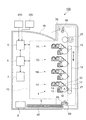
図1は、本実施の形態が適用される画像形成装置100を示す概略構成図である。
図1に示す画像形成装置100は、所謂タンデム型のカラープリンタである。この画像形成装置100は、各色の画像データに対応して画像形成を行う画像形成部10を備えている。またこの画像形成装置100は、画像形成装置100全体の動作を制御する制御部5と、例えばパーソナルコンピュータ(PC)200や画像読取装置300等といった外部装置に接続され、これらから受信される画像データに対して予め定められた画像処理を施す画像処理部6と、ユーザの操作によってなされた指示を受け付けるユーザ・インターフェイス7とを備えている。さらにこの画像形成装置100は、各部に電力を供給する電力供給部8を備えている。さらにまた、この画像形成装置100は、画像形成部10に供給される用紙(記録材)Sを積載する用紙積載部40と、画像形成部10によって画像が形成された用紙Sを積載する排紙積載部46とを備えている。
Embodiments of the present invention will be described below in detail with reference to the accompanying drawings.
<
FIG. 1 is a schematic configuration diagram illustrating an
An
<画像形成部10>
画像形成部10には、予め定められた間隔をおいて並列的に配置される4つの画像形成ユニット1(具体的には1Y,1M,1C,1K)が備えられている。また、画像形成部10は、各画像形成ユニット1にて形成された各色トナー像を多重転写させるため用紙Sを搬送する搬送ベルト18と、搬送ベルト18を回転させる駆動ロール19と、各画像形成ユニット1にて形成された各色トナー像を用紙Sに転写する転写ロール21と、転写された各色トナー像を用紙Sに定着させる定着装置25とを備えている。
また、画像形成部10は、用紙積載部40に積載された用紙Sを順次送り出すピックアップローラ68と、このピックアップローラ68によって送りだされた用紙Sを搬送する搬送ロール69とを備えている。さらに画像形成部10は、定着装置25においてトナー像が定着された用紙Sの通過を検知するエグジットセンサ70を有する。
<
The
In addition, the
<画像形成ユニット1>
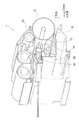
図2は、画像形成ユニット1を示す概略構成図である。
各画像形成ユニット1は、静電潜像を形成してトナー像を保持する感光体ドラム(像保持体)12と、この感光体ドラム12の表面を予め定められた電位で一様に帯電する帯電器13と、この帯電器13によって帯電された感光体ドラム12を画像データに基づいて露光するLEDプリントヘッド(LPH)14と、感光体ドラム12上に形成された静電潜像を現像剤を用いて現像する現像装置20と、転写後の感光体ドラム12表面を清掃するクリーナ16とを備えている。また、画像形成ユニット1は、LPH14に接続され、制御部5および画像処理部6との間で制御信号の送受信や電力供給部8からの電力供給を受ける折り曲げ可能なリード線の一態様であるフレキシブルフラットケーブル(FFC)50と、LPH14等を支持する支持筐体60とを備えている。なお、LPH14および支持筐体60を露光装置として捉えることができる。
<
FIG. 2 is a schematic configuration diagram showing the
Each
各画像形成ユニット1Y,1M,1C,1Kは、現像装置20に収納されるトナーを除いて、略同様に構成される。そして、各画像形成ユニット1Y,1M,1C,1Kは、それぞれがイエロー(Y)、マゼンタ(M)、シアン(C)、黒(K)のトナー像を形成する。
なお、以下の説明では、LPH14の長手方向(主走査方向、配列方向)をX方向とし、LPH14から感光体ドラム14に向けて照射される光の光軸方向(光照射方向)をZ方向とし、これらX方向およびZ方向と直交する方向をY方向とする。
The
In the following description, the longitudinal direction (main scanning direction, arrangement direction) of the
<画像形成装置100の動作>
再び図1を参照しながら、画像形成装置100の動作について説明をする。
本実施の形態の画像形成装置100において、PC200や画像読取装置300から入力された画像データは、画像処理部6によって予め定められた画像処理が施された後、不図示のインターフェースを介して各画像形成ユニット1に送られる。そして、例えば黒(K)色トナー像を形成する画像形成ユニット1Kでは、感光体ドラム12が矢印A方向に回転しながら、帯電器13により予め定められた電位で一様に帯電され、画像処理部6から送信された画像データに基づいてLPH14により走査露光される。それにより、感光体ドラム12上には、黒(K)色画像に関する静電潜像が形成される。そして、感光体ドラム12上に形成された静電潜像は、現像装置20により現像され、感光体ドラム12上には黒(K)トナー像が形成される。同様に、画像形成ユニット1Y,1M,1Cにおいても、それぞれイエロー(Y)、マゼンタ(M)、シアン(C)の各色のトナー像が形成される。
<Operation of
The operation of the
In the
一方で、用紙積載部40に積載された用紙Sは、ピックアップローラ68によって送り出される。そして、ピックアップローラ68によって送り出された用紙Sは、矢印B方向に移動する搬送ベルト18により搬送されながら、各画像形成ユニット1で形成された各色のトナー像が重畳される。そして、重畳トナー像が静電転写された用紙Sは、搬送ベルト18から剥離され、定着装置25まで搬送される。用紙S上のトナー像は、定着装置25によって熱および圧力による定着処理を受けて、用紙S上に定着される。そして、定着画像が形成された用紙Sは、搬送ロール69によってさらに搬送され、エグジットセンサ70によって検知された後、排紙積載部46に積載される。
On the other hand, the paper S stacked on the
<LPH14>
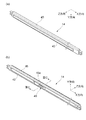
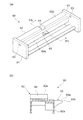
図3−1および図3−2は、LPH14の概略構成を説明するための図である。より詳細には、図3−1(a)はLPH14の光照射側(以下、表面側と呼ぶ)から見た斜視図であり、図3―1(b)はLPH14の光照射側とは反対側(以下、裏面側と呼ぶ)から見た斜視図であり、図3−2(c)は図3−1(b)のIIIcにおける断面図であり、図3−2(d)はFFC50が接続されたLPH14の裏面側から見た斜視図である。
<LPH14>
FIGS. 3A and 3B are diagrams for explaining a schematic configuration of the
露光部の一例であるLPH14は、発光チップアレイ41(後述する図4参照)と、発光チップアレイ41が設けられる回路基板42と、発光チップアレイ41から出射された光を感光体ドラム12(図2参照)表面に結像させるロッドレンズアレイ43とを備えている。また、LPH14は、回路基板42およびロッドレンズアレイ43を支持するとともに、回路基板42に設けられた発光チップアレイ41を外部から遮蔽する樹脂製のホルダ45を備えている。さらに、LPH14は、回路基板42の長手方向中央部に搭載され、FFC(取付部材、ケーブル)50を接続する接続部(被取付箇所、コネクタ)49を備えている。
The
ここで、図3−2(c)に示す断面において、回路基板42の断面における長手方向(Y方向)と、ホルダ45の断面における長手方向(Z方向)とは交差する関係にある。
また、図3−2(c)に示すように、接続部49は、所謂水平タイプコネクタである。具体的に説明をすると、接続部49は、FFC50の端子50a(後述する図7参照)と電気的に接続される接続端子49aを備える。この接続端子49aは、回路基板42の搭載面に沿う方向(図示の例においてはY方向)に向けて配置される。そして、図3−2(d)に示すように、接続端子49aには、FFC50がY方向に沿う方向に延びる姿勢(図中矢印I参照)で装着される。
Here, in the cross section shown in FIG. 3C, the longitudinal direction (Y direction) in the cross section of the
Moreover, as shown to FIG. 3-2 (c), the
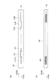
図4は、LPH14を構成する部材を説明するための図である。より詳細には、図4(a)はLPH14における発光チップアレイ41の上面図であり、図4(b)はLPH14におけるロッドレンズアレイ43およびホルダ45の上面図である。
図4(a)に示すように、発光チップアレイ41は、複数のLEDを備えた60個の発光チップC(C1〜C60)を含んで構成され、Y方向に二列で、所謂千鳥状に配置して構成されている。
FIG. 4 is a view for explaining members constituting the
As shown in FIG. 4A, the light-emitting
また、図4(b)に示すように、ロッドレンズアレイ43は、複数のロッドレンズ44を、互い違いになるようにY方向で二列に配列した状態で、ホルダ45に保持させることによって構成されている。各ロッドレンズ44は、例えば円柱状の形状をしており、その半径方向に屈折率分布を有し正立等倍実像を形成する屈折率分布型レンズにて構成される。このような屈折率分布型レンズとしては、例えばセルフォック(登録商標)レンズが挙げられる。
Further, as shown in FIG. 4B, the
<支持筐体60>
図5は、支持筐体60を示す概略構成図である。より詳細には、図5(a)は支持筐体60の斜視図であり、図5(b)は図5(a)のVbにおける断面図である。
支持部の一例である支持筐体60は、図5(a)に示すように、互いに離間して配置される支持板61と、支持板61間を接続する梁部62とを備える。
支持板61には、LPH14の端部が内部に挿入され、この端部を支持する支持孔63が形成される。
<Supporting
FIG. 5 is a schematic configuration diagram showing the
As shown in FIG. 5A, the
An end portion of the
梁部62は、感光体ドラム12(図2参照)側に向けて配置される側面である第1面62aと、現像装置20(図2参照)側に向けて配置される側面である第2面62bとを備える。また、梁部62には、第2面62bに形成され、FFC50を通す溝である切り欠き64が形成される。
The
ここで、図5(b)に示すように、梁部62は、第1面62aから感光体ドラム12側(図中右側、図2参照)に向けて突出し、LPH14と対峙するように設けられるとともに、LPH14の移動を規制する規制部65が形成される。この規制部65は、LPH14のホルダ45に沿う面65aと、梁部62の第1面62aから最も突出する先端65bとを備える。図示の例においては、梁部62の長手方向中央部に複数(2つ)の規制部65が設けられている。
Here, as shown in FIG. 5B, the
<LPH14の組み付け>
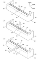
図6は、LPH14の組み付け方法を説明するための図である。
まず、図6(a)に示すように、支持筐体60に対して、LPH14を装着する。具体的には、支持板61の支持孔63に、所謂嵌め殺し方式でLPH14の両端を挿入する。
そして、図6(b)に示すように、LPH14の接続部49にFFC50を接続する。このとき、接続部49の接続端子49aに対して、Y方向に沿う姿勢のFFC50が装着される。
<Assembly of LPH14>
FIG. 6 is a diagram for explaining a method of assembling the
First, as shown in FIG. 6A, the
And as shown in FIG.6 (b), FFC50 is connected to the
そして、図6(c)に示すように、FFC50を切り欠き64内に配置するよう、FFC50を曲げる。具体的には、組立作業者がFFC50における接続部49近傍の部分を指等で押圧することにより、FFC50が曲げられる。このようにFFC50を曲げることにより、LPH14の図中上方に現像装置20を配置する空間を確保する(図2参照)。
Then, as shown in FIG. 6C, the
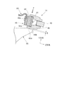
図7は、FFC50を曲げる際にLPH14に加わる力を説明するための図である。より詳細には、図7は図6(c)のVIIにおける断面図である。
接続部49に接続したFFC50を曲げることにより、接続部49が設けられているLPH14全体はY方向に沿う向きの力を受ける(図中矢印F参照)。なお、この力の向きは、発光チップアレイ41の光軸と交差する向き(回路基板42の面に沿う向き)である。
FIG. 7 is a diagram for explaining the force applied to the
By bending the
さらに説明をすると、図7に示すように、LPH14に加わる力は、回路基板42の断面における長手方向(Y方向)に沿う向きに回路基板42を押圧する力であるから、例えば長手方向と交差する向きの力(Z方向に沿った力)を受ける場合と比較して、回路基板42は撓みにくい。また、ホルダ45の断面における長手方向(Z方向)と交差する向きにホルダ45を押圧する力であるから、例えば長手方向に沿う向きの力(Z方向に沿った力)を受ける場合と比較して、ホルダ45は撓みやすい向きである。
More specifically, as shown in FIG. 7, the force applied to the
ここで、LPH14がY方向に沿う向きに力を受ける(図中矢印F参照)ことにより、LPH14に撓みが生じる。このとき、LPH14が予め定めた範囲を超えて撓むと、例えばLPH14の内部のワイヤボンディング等配線が断線する、あるいは発光チップアレイ41を構成する発光チップC(図4(a)参照)が回路基板42から剥離する等して内部で損傷(内部破壊)を受ける。また、ホルダ45に歪みが生じ、発光チップアレイ41やロッドレンズアレイ43等の光学部材の位置や向きがずれる。これらのことにより、LPH14によって感光体ドラム12上に形成される静電潜像の画質を低下させる。
Here, when LPH14 receives force in the direction along the Y direction (see arrow F in the figure), the LPH14 bends. At this time, if the
しかしながら、本実施の形態においては、上述のように支持筐体60に規制部65が設けられている。そして、この規制部65がFFC50を曲げる際に撓んだLPH14を支持する(突っ張る)ことで、LPH14が過度に撓むことを抑制する。
さて、規制部65は、LPH14が力を受けていない(撓んでいない)通常の状態においては、LPH14から離間している(図中距離δ参照)。規制部65とLPH14とが離間していることにより、通常の状態において、LPH14が規制部65から力を受けLPH14が撓むことで、静電潜像の画質を低下させることが抑制される。
However, in the present embodiment, the restricting
Now, the restricting
また、規制部65は、LPH14がFFC50を曲げることにともない力を受けた際にホルダ45と接触する位置に配置されている。なお、距離δは、LPH14に上述したような不具合が生じさせないよう、LPH14に不具合が発生するLPH14の変位量よりも小さくなるよう定められる。
Further, the restricting
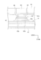
<LPH14と規制部65との配置>
図8は、図6(c)のVIII方向から見た概略構成図である。
さて、本実施の形態における規制部65は、LPH14の近傍であり、LPH14の接続部49に対応する位置に配置されている。さらに説明をすると、図8に示すように、規制部65は、力の向きに見て、規制部65と接続部49とが交差するように配置され、X方向およびZ方向において、接続部49の位置と重複する。このことにより、規制部65は、FFC50を曲げることにともなう力を受けた際に、LPH14が最も撓む部分を支持する。
<Arrangement of
FIG. 8 is a schematic configuration diagram seen from the VIII direction of FIG.
Now, the restricting
また、規制部65は、回路基板42に対応する位置に配置されている。さらに説明をすると、図8に示すように、規制部65は、力の向きに見て、規制部65と回路基板42とが交差するように配置され、X方向およびZ方向において、回路基板42の位置と重複する。このことにより、回路基板42が変形し、LPH14が形成する静電画像の画質が劣化することが抑制される。
なお、規制部65を図示のように規制部65と回路基板42とが交差するように配置した場合、回路基板42と交差しない配置(先端65bが回路基板42よりも第1面62a側となる配置)と比較して、回路基板42が撓むことがより確実に抑制される。
Further, the restricting
When the restricting
さて、上記の説明においては、FFC50を曲げる際にLPH14が撓むことを説明したが、LPH14を撓ませる力は、FFC50を曲げる際に加わる力に限定されるものではない。例えば、感光体ドラム12あるいは現像装置20のカートリッジを交換する際や、ロッドレンズアレイ43のレンズ面の清掃の際に、作業者が誤って触れた場合にもLPH14に力が加わる。これらの場合においても、規制部65はLPH14の撓みを規制する。
In the above description, it has been described that the
また、上記の説明においては、規制部65が、梁部62に設けられることを説明したが、規制部65がLPH14の撓みを規制可能な位置であれば、他の部材に設けられてもよい。例えば、LPH14を覆うカバー部材付きのLPH14である場合には、カバー部材に規制部65が設けられてもよい。
Further, in the above description, it has been described that the restricting
また、上記の説明においては、規制部65が、梁部62の長手方向中央部に設けられることを説明したが、規制部65がLPH14の撓みを規制可能な位置であれば、この配置に限定されない。例えば、接続部49がLPH14の端部側に設けられた場合には、この接続部49の位置に対応するよう規制部65が梁部62の端部側に設けられてもよい。
In the above description, it has been described that the restricting
1…画像形成ユニット、12…感光体ドラム、14…LPH、41…発光チップアレイ、42…回路基板、43…ロッドレンズアレイ、45…ホルダ、49…接続部、49a…接続端子、50…FFC、65…規制部、100…画像形成装置
DESCRIPTION OF
Claims (5)
前記露光部を支持する支持部と、
前記支持部によって支持された前記露光部が、前記発光体の光軸方向および当該発光体の配列方向と交差する向きに力を受け撓んだ際に、当該露光部を支持し当該露光部の撓みを規制するとともに、当該向きに当該力を受けていない当該露光部から離間する位置に設けられる規制部と
を備える露光装置。 An exposure unit that has a plurality of light emitters arranged along the rotational axis direction of the rotating image carrier and exposes the image carrier;
A support part for supporting the exposure part;
When the exposure unit supported by the support unit is subjected to a force in a direction crossing the optical axis direction of the light emitter and the arrangement direction of the light emitter, the exposure unit is supported and the exposure unit while restricting the deflection, Ru exposure apparatus and a restricting portion provided at a position apart from the exposure unit not receiving the force to the facing.
前記規制部は、前記被取付箇所に前記取付部材を取り付けることにともない前記交差する向きに前記力を受けて撓む前記露光部を支持することを特徴とする請求項1記載の露光装置。 The exposure unit includes an attachment location for attaching an attachment member attached to the exposure unit supported by the support unit,
The exposure apparatus according to claim 1, wherein the restricting portion supports the exposure portion that is bent by receiving the force in the intersecting direction when the attachment member is attached to the attachment location.
前記像保持体の回転軸方向に沿って配列される複数の発光体を有し当該像保持体を露光する露光部と、
前記露光部を支持する支持部と、
前記支持部に支持された前記露光部に取り付けられる取付部材と、
前記支持部に支持された前記露光部が、前記取付部材を取り付けることにともなって前記発光体の光軸方向および当該発光体の配列方向と交差する向きに力を受け撓んだ際に、当該露光部を支持し当該露光部の撓みを規制するとともに、当該向きに当該力を受けていない当該露光部から離間する位置に設けられる規制部と
を備える画像形成装置。 A rotating image carrier;
An exposure unit that has a plurality of light emitters arranged along the rotation axis direction of the image carrier, and exposes the image carrier;
A support part for supporting the exposure part;
An attachment member attached to the exposure part supported by the support part;
When the exposure portion supported by the support portion is bent by receiving a force in a direction crossing the optical axis direction of the light emitters and the arrangement direction of the light emitters as the attachment member is attached, supporting the exposed portion while restricting the deflection of the exposure unit, the image forming apparatus Ru and a restricting portion provided at a position apart from the exposure unit not receiving the force to the facing.
前記露光部は、前記ケーブルを取り付けるコネクタを備え、
前記規制部は、前記コネクタに取り付けられた前記ケーブルを曲げることにともない前記露光部が撓んだ際に、当該露光部を支持することを特徴とする請求項4記載の画像形成装置。 The attachment member is a cable that supplies a control signal to the exposure unit,
The exposure unit includes a connector for attaching the cable,
The image forming apparatus according to claim 4 , wherein the restricting portion supports the exposure portion when the exposure portion is bent as the cable attached to the connector is bent.
Priority Applications (1)
| Application Number | Priority Date | Filing Date | Title |
|---|---|---|---|
| JP2013029673A JP5994673B2 (en) | 2013-02-19 | 2013-02-19 | Exposure apparatus and image forming apparatus |
Applications Claiming Priority (1)
| Application Number | Priority Date | Filing Date | Title |
|---|---|---|---|
| JP2013029673A JP5994673B2 (en) | 2013-02-19 | 2013-02-19 | Exposure apparatus and image forming apparatus |
Publications (2)
| Publication Number | Publication Date |
|---|---|
| JP2014159087A JP2014159087A (en) | 2014-09-04 |
| JP5994673B2 true JP5994673B2 (en) | 2016-09-21 |
Family
ID=51611207
Family Applications (1)
| Application Number | Title | Priority Date | Filing Date |
|---|---|---|---|
| JP2013029673A Expired - Fee Related JP5994673B2 (en) | 2013-02-19 | 2013-02-19 | Exposure apparatus and image forming apparatus |
Country Status (1)
| Country | Link |
|---|---|
| JP (1) | JP5994673B2 (en) |
Families Citing this family (2)
| Publication number | Priority date | Publication date | Assignee | Title |
|---|---|---|---|---|
| JP6477053B2 (en) * | 2015-03-10 | 2019-03-06 | 富士ゼロックス株式会社 | Wire bonding method and substrate device manufacturing method |
| JP7207914B2 (en) * | 2017-10-27 | 2023-01-18 | キヤノン株式会社 | Image forming apparatus with optical print head |
Family Cites Families (3)
| Publication number | Priority date | Publication date | Assignee | Title |
|---|---|---|---|---|
| JP2007090721A (en) * | 2005-09-29 | 2007-04-12 | Nippon Seiki Co Ltd | LED print head |
| JP5205839B2 (en) * | 2007-07-04 | 2013-06-05 | 富士ゼロックス株式会社 | Image forming apparatus |
| JP2011133773A (en) * | 2009-12-25 | 2011-07-07 | Fuji Xerox Co Ltd | Exposure device and image forming device |
-
2013
- 2013-02-19 JP JP2013029673A patent/JP5994673B2/en not_active Expired - Fee Related
Also Published As
| Publication number | Publication date |
|---|---|
| JP2014159087A (en) | 2014-09-04 |
Similar Documents
| Publication | Publication Date | Title |
|---|---|---|
| US10712711B2 (en) | Drum cartridge in which first storage medium of toner catridge and second storage medium of drum catridge are aligned in mounting direction, and image forming apparatus to which drum catridge is mountable | |
| US7999838B2 (en) | Line head, image forming apparatus incorporating the same, and method of adjusting position of the same | |
| JP5186891B2 (en) | Image forming apparatus | |
| US8960853B2 (en) | Image forming apparatus and exposure device | |
| US11042103B2 (en) | Image forming apparatus having optical print head | |
| US9395671B1 (en) | Image forming apparatus and sheet transport device | |
| US11249434B2 (en) | Image forming apparatus including optical print head | |
| JP2011133773A (en) | Exposure device and image forming device | |
| US8755715B2 (en) | Image forming apparatus having LED head and rotatable cover | |
| JP5994673B2 (en) | Exposure apparatus and image forming apparatus | |
| JP6051926B2 (en) | Light emitting device and image forming apparatus | |
| JP7024192B2 (en) | Power supply structure and image forming device | |
| CN112485991A (en) | Image forming apparatus with a toner supply device | |
| US10015352B2 (en) | Exposure device having a plurality of first and second light emitting elements, LED head as the exposure device, image forming apparatus including the exposure device, and image reading apparatus | |
| US8416497B2 (en) | Lens array unit, optical head and information apparatus | |
| EP2085228B1 (en) | Image forming apparatus having a lens array. | |
| US10969732B2 (en) | Image forming apparatus including optical print head | |
| US20080225107A1 (en) | Line Head, and an Image Forming Apparatus and an Image Forming Method Using the Line Head | |
| JP6969284B2 (en) | Exposure equipment and image forming equipment | |
| CN101470379A (en) | An exposure head and an image forming apparatus | |
| US7995084B2 (en) | Line head and an image forming apparatus using the line head | |
| US20200174420A1 (en) | Image forming apparatus including optical print head | |
| US12298679B2 (en) | Print head | |
| JP7067461B2 (en) | Image forming device | |
| JP7027868B2 (en) | Light emitting board, exposure device and image forming device |
Legal Events
| Date | Code | Title | Description |
|---|---|---|---|
| A621 | Written request for application examination |
Free format text: JAPANESE INTERMEDIATE CODE: A621 Effective date: 20150819 |
|
| A977 | Report on retrieval |
Free format text: JAPANESE INTERMEDIATE CODE: A971007 Effective date: 20160426 |
|
| A131 | Notification of reasons for refusal |
Free format text: JAPANESE INTERMEDIATE CODE: A131 Effective date: 20160510 |
|
| A521 | Request for written amendment filed |
Free format text: JAPANESE INTERMEDIATE CODE: A523 Effective date: 20160701 |
|
| TRDD | Decision of grant or rejection written | ||
| A01 | Written decision to grant a patent or to grant a registration (utility model) |
Free format text: JAPANESE INTERMEDIATE CODE: A01 Effective date: 20160726 |
|
| A61 | First payment of annual fees (during grant procedure) |
Free format text: JAPANESE INTERMEDIATE CODE: A61 Effective date: 20160808 |
|
| R150 | Certificate of patent or registration of utility model |
Ref document number: 5994673 Country of ref document: JP Free format text: JAPANESE INTERMEDIATE CODE: R150 |
|
| S533 | Written request for registration of change of name |
Free format text: JAPANESE INTERMEDIATE CODE: R313533 |
|
| R350 | Written notification of registration of transfer |
Free format text: JAPANESE INTERMEDIATE CODE: R350 |
|
| LAPS | Cancellation because of no payment of annual fees |