JP5992471B2 - Racket and grommet - Google Patents
Racket and grommet Download PDFInfo
- Publication number
- JP5992471B2 JP5992471B2 JP2014103998A JP2014103998A JP5992471B2 JP 5992471 B2 JP5992471 B2 JP 5992471B2 JP 2014103998 A JP2014103998 A JP 2014103998A JP 2014103998 A JP2014103998 A JP 2014103998A JP 5992471 B2 JP5992471 B2 JP 5992471B2
- Authority
- JP
- Japan
- Prior art keywords
- racket
- side opening
- grommet
- frame
- string
- Prior art date
- Legal status (The legal status is an assumption and is not a legal conclusion. Google has not performed a legal analysis and makes no representation as to the accuracy of the status listed.)
- Active
Links
Images


Classifications
-
- A—HUMAN NECESSITIES
- A63—SPORTS; GAMES; AMUSEMENTS
- A63B—APPARATUS FOR PHYSICAL TRAINING, GYMNASTICS, SWIMMING, CLIMBING, OR FENCING; BALL GAMES; TRAINING EQUIPMENT
- A63B49/00—Stringed rackets, e.g. for tennis
- A63B49/02—Frames
- A63B49/022—String guides on frames, e.g. grommets
-
- A—HUMAN NECESSITIES
- A63—SPORTS; GAMES; AMUSEMENTS
- A63B—APPARATUS FOR PHYSICAL TRAINING, GYMNASTICS, SWIMMING, CLIMBING, OR FENCING; BALL GAMES; TRAINING EQUIPMENT
- A63B51/00—Stringing tennis, badminton or like rackets; Strings therefor; Maintenance of racket strings
- A63B51/10—Reinforcements for stringing
-
- A—HUMAN NECESSITIES
- A63—SPORTS; GAMES; AMUSEMENTS
- A63B—APPARATUS FOR PHYSICAL TRAINING, GYMNASTICS, SWIMMING, CLIMBING, OR FENCING; BALL GAMES; TRAINING EQUIPMENT
- A63B49/00—Stringed rackets, e.g. for tennis
Description
本発明は、テニス等に使用されるラケット、および、ラケットに取り付けられるグロメットに関する。 The present invention relates to a racket used for tennis or the like, and a grommet attached to the racket.
テニス等に使用されるラケットのフレームには、ストリングを挿通するためのストリング孔が周方向に沿って複数設けられている。一般的に、複数の筒部とそれらを連結する基底部を備えるグロメットを介してフレームにストリングが張設される。そして、フレームに張られたストリングによりネット状の打面が形成される。 A racket frame used for tennis or the like is provided with a plurality of string holes along the circumferential direction for inserting strings. In general, a string is stretched on a frame via a grommet including a plurality of tube portions and a base portion connecting them. A net-like striking surface is formed by the string stretched on the frame.
特許文献1には、広いスイートエリアを得るように、ガットが押圧方向に摺動する通孔を有するガット保護体が開示されている。 Patent Document 1 discloses a gut protector having a through hole through which a gut slides in the pressing direction so as to obtain a wide sweet area.
テニス競技において打球の回転数を高めることができれば、相手コード内へと打球を落下させやすくなるなど、プレイヤーにとって利点が多い。よって、打球の回転数を高めることが望まれる。 If the number of rotations of the hit ball can be increased in the tennis game, there are many advantages for the player, such as making it easier to drop the hit ball into the opponent's code. Therefore, it is desired to increase the rotation speed of the hit ball.
本発明は、かかる事情に鑑みてなされたものであり、その目的とするところは、打球の回転数を高めることである。 The present invention has been made in view of such circumstances, and an object thereof is to increase the number of rotations of the hit ball.
上記目的を達成するための主たる発明は、
グリップと、
内周面から外周面まで貫通する貫通孔が複数設けられた環状のフレームと、
前記グリップと前記フレームを連結するシャフトと、
前記フレームの前記外周面に取り付けられるグロメットであって、前記フレームに設けられた複数の前記貫通孔にそれぞれ挿通される複数の筒部と、当該複数の筒部を連結する基底部と、を備えるグロメットと、
を有するラケットであって、
前記筒部は、前記基底部側の基底部側開口と、前記貫通孔内に挿通される側の先端側開口と、を連通する連通孔を有し、
前記ラケットの長手方向に沿う方向に張られるストリングが挿通される前記複数の筒部のうち、少なくとも一部の筒部の前記先端側開口は前記基底部側開口よりも前記複数の筒部が並ぶ方向に広く、
前記基底部側開口は丸孔であり、前記先端側開口は前記筒部が並ぶ方向が長径の長孔であることを特徴とするラケットである。
The main invention for achieving the above object is:
Grip,
An annular frame provided with a plurality of through holes penetrating from the inner peripheral surface to the outer peripheral surface;
A shaft connecting the grip and the frame;
A grommet attached to the outer peripheral surface of the frame, the grommet comprising a plurality of cylindrical portions respectively inserted into the plurality of through holes provided in the frame, and a base portion connecting the plurality of cylindrical portions. Grommet,
A racket having
The cylindrical portion has a communication hole that communicates the base portion side opening on the base portion side and the distal end side opening on the side inserted into the through hole,
Among the plurality of cylindrical portions through which the string stretched in the longitudinal direction of the racket is inserted, the plurality of cylindrical portions are arranged in the distal end side opening of at least a part of the cylindrical portion rather than the base side opening. widely in the direction,
The base side opening is a round hole, and the tip side opening is a racket having a long diameter in the direction in which the cylindrical parts are arranged .
本発明の他の特徴については、本明細書及び図面の記載により明らかにする。 Other features of the present invention will become apparent from the description of the present specification and the drawings.
本発明のラケットによれば、グロメットの先端側開口が基底部側開口よりも複数の筒部が並ぶ方向に広いので、ボールをこすり上げるように打った場合に、ラケットの長手方向に沿う方向に張られるストリング(以下、縦ストリングという)を長手方向と交差する方向(以下、交差方向)へとより大きく移動させやすくなる。また、縦ストリングは、基底部側開口側を支点として移動するため、交差方向に移動した直後にボールと接触しながら元の位置へと戻る。これにより、ボールと接触している間の縦ストリングの移動量を一般的なラケットと比較して大きくすることができる。打球の回転数は、ボールに接触している間のストリングの移動量に対応して大きくなるため、上記ラケットによれば、打球の回転数を高めることができる。 According to the racket of the present invention, the front end side opening of the grommet is wider in the direction in which the plurality of cylindrical portions are aligned than the base side opening, so that when the ball is rubbed up, the grommet extends in the direction along the longitudinal direction of the racket. A string to be stretched (hereinafter referred to as a vertical string) can be more easily moved in a direction crossing the longitudinal direction (hereinafter referred to as a crossing direction). Further, since the vertical string moves with the base side opening side as a fulcrum, immediately after moving in the crossing direction, the vertical string returns to the original position while contacting the ball. Thereby, the amount of movement of the vertical string while in contact with the ball can be increased as compared with a general racket. Since the number of rotations of the hit ball increases corresponding to the amount of movement of the string while in contact with the ball, the number of rotations of the hit ball can be increased according to the racket.
===開示の概要===
本明細書及び図面の記載により、少なくとも、以下の事項が明らかとなる。
すなわち、グリップと、
内周面から外周面まで貫通する貫通孔が複数設けられた環状のフレームと、
前記グリップと前記フレームを連結するシャフトと、
前記フレームの前記外周面に取り付けられるグロメットであって、前記フレームに設けられた複数の前記貫通孔にそれぞれ挿通される複数の筒部と、当該複数の筒部を連結する基底部と、を備えるグロメットと、
を有するラケットであって、
前記筒部は、前記基底部側の基底部側開口と、前記貫通孔内に挿通される側の先端側開口と、を連通する連通孔を有し、
前記ラケットの長手方向に沿う方向に張られるストリングが挿通される前記複数の筒部のうち、少なくとも一部の筒部の前記先端側開口は前記基底部側開口よりも前記複数の筒部が並ぶ方向に広いことを特徴とするラケットである。
このようなラケットによれば、グロメットの先端側開口が基底部側開口よりも複数の筒部が並ぶ方向に広いので、ボールをこすり上げるように打った場合に、ラケットの長手方向に沿う方向に張られるストリング(以下、縦ストリングという)を長手方向と交差する方向(以下、交差方向)へとより大きく移動させやすくなる。また、縦ストリングは、基底部側開口側を支点として移動するため、交差方向に移動した直後にボールと接触しながら元の位置へと戻る。これにより、ボールと接触している間の縦ストリングの移動量を一般的なラケットと比較して大きくすることができる。打球の回転数は、ボールに接触している間のストリングの移動量に対応して大きくなるため、上記ラケットによれば、打球の回転数を高めることができる。
=== Summary of disclosure ===
At least the following matters will become clear from the description of the present specification and the drawings.
That is, grip and
An annular frame provided with a plurality of through holes penetrating from the inner peripheral surface to the outer peripheral surface;
A shaft connecting the grip and the frame;
A grommet attached to the outer peripheral surface of the frame, the grommet comprising a plurality of cylindrical portions respectively inserted into the plurality of through holes provided in the frame, and a base portion connecting the plurality of cylindrical portions. Grommet,
A racket having
The cylindrical portion has a communication hole that communicates the base portion side opening on the base portion side and the distal end side opening on the side inserted into the through hole,
Among the plurality of cylindrical portions through which the string stretched in the longitudinal direction of the racket is inserted, the plurality of cylindrical portions are arranged in the distal end side opening of at least a part of the cylindrical portion rather than the base side opening. It is a racket characterized by being wide in the direction.
According to such a racket, the opening on the tip side of the grommet is wider in the direction in which the plurality of cylindrical portions are aligned than the opening on the base side, so that when the ball is rubbed up, the opening is in the direction along the longitudinal direction of the racket. A string to be stretched (hereinafter referred to as a vertical string) can be more easily moved in a direction crossing the longitudinal direction (hereinafter referred to as a crossing direction). Further, since the vertical string moves with the base side opening side as a fulcrum, immediately after moving in the crossing direction, the vertical string returns to the original position while contacting the ball. Thereby, the amount of movement of the vertical string while in contact with the ball can be increased as compared with a general racket. Since the number of rotations of the hit ball increases corresponding to the amount of movement of the string while in contact with the ball, the number of rotations of the hit ball can be increased according to the racket.
かかるラケットであって、前記グロメットは、前記長手方向における前記フレームの先端側および後端側の少なくともいずれか一方に取り付けられることを特徴とするラケットである。
このようにすることで、上記グロメットの少なくとも一部の筒部に縦ストリングを張ることができる。そして、縦ストリングの移動量を多くして、打球の回転数を高めることができる。
In this racket, the grommet is attached to at least one of a front end side and a rear end side of the frame in the longitudinal direction.
By doing in this way, a vertical string can be stretched on at least a part of the cylindrical part of the grommet. Then, the amount of movement of the vertical string can be increased to increase the rotation number of the hit ball.
かかるラケットであって、前記基底部側開口は丸孔であり、前記先端側開口は前記筒部が並ぶ方向が長径の長孔であることを特徴とするラケットである。
このようにすることで、複数の筒部が並ぶ方向に先端側開口を基底部側開口よりも広くすることができる。
In this racket, the base side opening is a round hole, and the tip side opening is a long hole having a long diameter in the direction in which the cylindrical portions are arranged.
By doing in this way, a front end side opening can be made wider than a base part side opening in the direction where a plurality of cylinder parts are arranged.
また、前記筒部が並ぶ方向と交差する方向において、前記基底部側開口の大きさと前記先端側開口の大きさとが等しいことを特徴とするラケットである。
このようにすることで、グロメットをラケットに取り付けたときに、ラケットの厚み方向については、基底部側開口の径と先端側開口の径とを等しくすることができるので、縦ストリングを複数の筒部が並ぶ方向に沿って移動させることができる。
The racket is characterized in that the size of the base side opening and the size of the tip side opening are equal in a direction intersecting the direction in which the tube parts are arranged.
In this way, when the grommet is attached to the racket, the diameter of the base side opening and the diameter of the tip side opening can be made equal in the thickness direction of the racket. It can be moved along the direction in which the parts are arranged.
また、さらに、前記長手方向に交差する方向に沿う方向に張られるストリングが挿通される複数の筒部を有するサイドグロメットを有し、当該サイドグロメットの筒部のうち、少なくとも一部の筒部が前記ラケットの厚さ方向に拡がる長孔を有することを特徴とするラケットである。
このようにすることで、ボールと接触したときにおいて、交差方向に沿う方向に張られるストリング(以下、横ストリングという)をラケットの厚み方向に移動させやすくすることができる。これにより、ラケットに対するボールの反発力が高まるが、上記のような構成によりボールの前方方向の回転数を高めることができるので、ボールを適切に相手コート内に落下させることができる。
Furthermore, it has a side grommet which has a plurality of cylinder parts by which the string stretched in the direction which intersects the direction which intersects the longitudinal direction is penetrated, and at least some cylinder parts among the cylinder parts of the side grommet concerned The racket has a long hole extending in the thickness direction of the racket.
By doing so, it is possible to easily move a string stretched in a direction along the intersecting direction (hereinafter referred to as a horizontal string) in the racket thickness direction when contacting the ball. Thereby, although the repulsive force of the ball with respect to the racket is increased, the number of rotations in the forward direction of the ball can be increased by the configuration as described above, so that the ball can be appropriately dropped into the opponent's court.
また、本明細書及び図面の記載により、少なくとも、以下の事項も明らかとなる。
すなわち、グリップと、
内周面から外周面まで貫通する貫通孔が複数設けられた環状のフレームと、
前記グリップと前記フレームを連結するシャフトと、
を有するラケットであって、
前記貫通孔は、前記外周面側の外周面側開口と、前記内周面側の内周面側開口と、を有し、
前記ラケットの長手方向に沿う方向に張られるストリングが挿通される前記複数の貫通孔のうち、少なくとも一部の貫通孔の前記内周側開口は前記外周側開口よりも前記複数の貫通孔が並ぶ方向に広いことを特徴とするラケットである。
このようなラケットによれば、内周側開口が外周側開口よりも複数の筒部が並ぶ方向に広いので、ボールをこすり上げるように打った場合に、縦ストリングを交差方向へとより大きく移動させやすくなる。また、縦ストリングは、外周側開口側を支点として移動するため、交差方向に移動した直後にボールと接触しながら元の位置へと戻る。これにより、ボールと接触している間の縦ストリングの移動量を一般的なラケットと比較して大きくすることができる。打球の回転数は、ボールに接触している間のストリングの移動量に対応して大きくなるため、上記ラケットによれば、打球の回転数を高めることができる。
In addition, at least the following matters will become clear from the description of the present specification and the drawings.
That is, the grip,
An annular frame provided with a plurality of through holes penetrating from the inner peripheral surface to the outer peripheral surface;
A shaft connecting the grip and the frame;
A racket having
The through hole has an outer peripheral surface side opening on the outer peripheral surface side, and an inner peripheral surface side opening on the inner peripheral surface side,
Among the plurality of through holes through which the string stretched in the longitudinal direction of the racket is inserted, the plurality of through holes are arranged in the inner peripheral side opening of at least a part of the through holes rather than the outer peripheral side opening. It is a racket characterized by being wide in the direction.
According to such a racket, the inner circumferential side opening is wider than the outer circumferential side opening in the direction in which a plurality of cylindrical portions are arranged, so that when the ball is rubbed up, the vertical string is moved more in the crossing direction. It becomes easy to let you. Moreover, since the vertical string moves using the outer peripheral side opening side as a fulcrum, immediately after moving in the crossing direction, the vertical string returns to the original position while contacting the ball. Thereby, the amount of movement of the vertical string while in contact with the ball can be increased as compared with a general racket. Since the number of rotations of the hit ball increases corresponding to the amount of movement of the string while in contact with the ball, the number of rotations of the hit ball can be increased according to the racket.
また、本明細書及び図面の記載により、少なくとも、以下の事項も明らかとなる。
すなわち、グリップと、内周面から外周面まで貫通する貫通孔が複数設けられた環状のフレームと、前記グリップと前記フレームを連結するシャフトと、を有するラケットに取り付けられるグロメットであって、
前記フレームに設けられた複数の前記貫通孔にそれぞれ挿通される複数の筒部と、当該複数の筒部を連結する基底部と、を備え、
前記筒部は、前記基底部側の基底部側開口と、前記貫通孔内に挿通される側の先端側開口と、を連通する連通孔を有し、
前記ラケットの長手方向に沿う方向に張られるストリングが挿通される前記複数の筒部のうち、少なくとも一部の筒部の前記先端側開口は前記基底部側開口よりも前記複数の筒部が並ぶ方向に広いことを特徴とするグロメットである。
このようなグロメットによれば、グロメットの先端側開口が基底部側開口よりも複数の筒部が並ぶ方向に広いので、ボールをこすり上げるように打った場合に、縦ストリングを交差方向へとより大きく移動させやすくなる。また、縦ストリングは、基底部側開口側を支点として移動するため、交差方向に移動した直後にボールと接触しながら元の位置へと戻る。これにより、ボールと接触している間の縦ストリングの移動量を一般的なグロメットと比較して大きくすることができる。打球の回転数は、ボールに接触している間のストリングの移動量に対応して大きくなるため、上記グロメットによれば、打球の回転数を高めることができる。
In addition, at least the following matters will become clear from the description of the present specification and the drawings.
That is, a grommet attached to a racket having a grip, an annular frame provided with a plurality of through holes penetrating from the inner peripheral surface to the outer peripheral surface, and a shaft connecting the grip and the frame,
A plurality of cylindrical portions respectively inserted into the plurality of through-holes provided in the frame, and a base portion connecting the plurality of cylindrical portions,
The cylindrical portion has a communication hole that communicates the base portion side opening on the base portion side and the distal end side opening on the side inserted into the through hole,
Among the plurality of cylindrical portions through which the string stretched in the longitudinal direction of the racket is inserted, the plurality of cylindrical portions are arranged in the distal end side opening of at least a part of the cylindrical portion rather than the base side opening. A grommet that is wide in direction.
According to such a grommet, the opening on the front end side of the grommet is wider in the direction in which the plurality of cylindrical portions are aligned than the opening on the base side, so that when the ball is rubbed up, the vertical string is moved more in the crossing direction. It becomes easy to move greatly. Further, since the vertical string moves with the base side opening side as a fulcrum, immediately after moving in the crossing direction, the vertical string returns to the original position while contacting the ball. Thereby, the amount of movement of the vertical string while in contact with the ball can be increased as compared with a general grommet. Since the number of rotations of the hit ball increases corresponding to the amount of movement of the string while in contact with the ball, the number of rotations of the hit ball can be increased according to the grommet.
===ラケット1について===
以下、テニス用ラケットを例に挙げて実施形態を説明する。
=== About Racket 1 ===
Hereinafter, an embodiment will be described by taking a tennis racket as an example.
図1は、テニス用ラケット(以下、ラケット1)の平面図及び側面図である。なお、左図が平面図であり右図が側面図である。図2は、フレーム11にストリング12を張設する様子を説明する図である。ラケット1は、ボールを打つ部位であるヘッド10と、プレイヤーがラケット1を把持する部位であるグリップ20と、ヘッド10とグリップ20を一体に連結するシャフト30と、を有する。説明のため、ラケット1の長手方向のうちヘッド10が位置する側を先端側とし、グリップ20が位置する側を後端側とする。また、ラケット1の打面上において(即ち打面に沿う平面上において)長手方向に直交する方向を幅方向とし、ラケット1の打面に直交する方向を厚さ方向とする。
FIG. 1 is a plan view and a side view of a tennis racket (hereinafter referred to as a racket 1). The left figure is a plan view and the right figure is a side view. FIG. 2 is a diagram for explaining a state in which the
ヘッド10は、長手方向に延びた略楕円形状であるフレーム11と、フレーム11の内側に張設されたストリング12と、フレーム11の外周面11aに取り付けられたバンパーグロメット41と、ヨークグロメット42と、サイドグロメット43と、を有する。
The
図2に示すように、フレーム11の外周面11aの厚さ方向における中心部には、フレーム11の全周に亘って溝部111が設けられている。その溝部111に、フレーム11の内周面11bから外周面11aまで貫通する孔でありストリング12を挿通するための孔であるストリング孔13(貫通孔に相当)が設けられている。ストリング孔13はフレーム11の全周にわたって複数設けられている。
As shown in FIG. 2, a
ストリング12の張設についてバンパーグロメット41を例に説明を行う。なお、各グロメットの詳細な説明については後述する。
The tensioning of the
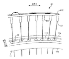
バンパーグロメット41は、複数の筒部411と、複数の筒部411を連結する基底部412と、を有する。筒部411は、連通孔を有し、この連通孔にストリング12を挿通可能となっている(詳細は後述)。バンパーグロメット41は、筒部411の先端部(基底部412に接続していない側の端部)がフレーム11の外周面11a側からストリング孔13に通され、また、基底部412がフレーム11の溝部111に嵌め込まれるようにして、フレーム11の外周面11aに取り付けられる。
The
フレーム11にストリング12が張設される際には、フレーム11の内側からバンパーグロメット41の筒部411内を通ってフレーム11の外側に出されたストリング12がバンパーグロメット41の基底部412に沿って折り返されて次の筒部411内に通される動作が繰り返される。その結果、フレーム11の内側に、長手方向に延びたストリング12の部位である縦ストリング121が幅方向に感覚を空けて複数本張られる。また、縦ストリング121と交差するように幅方向に延びたストリング12の部位である横ストリング122が長手方向に感覚を空けて複数本張られ、ネット状の打面が形成される。
When the
シャフト30は、図1の左図に示すように、グリップ20との接続部である基端部31と、基端部31からフレーム11の後端部のうちの幅方向における左側端部まで延びる第1分岐部32aと、第1基端部31からフレーム11の後端部のうちの幅方向における右側端部まで延びる第2分岐部32bと、を有する。つまり、シャフト30は、厚さ方向(ラケット1の打面に直交する方向)から見て、長手方向の先端側に向かって(グリップ20からフレーム11に向かう方向に)二股に分岐している。そのため、フレーム11の後端部と第1分岐部32a及び第2分岐部32bにより、厚さ方向に空いた開口部33が形成されている。
As shown in the left diagram of FIG. 1, the
===各グロメットについて===
図3は、フレーム11に取り付けられる各グロメットの説明図である。本実施形態のラケット1では、図3に示されるように、フレーム11の外周面11aに、バンパーグロメット41とヨークグロメット42とサイドグロメット43が取り付けられる。バンパーグロメット41、ヨークグロメット42、および、サイドグロメット43を介してフレーム11にストリング12を張設することで、後述する効果の他、ストリング12を保護したり、打球時の振動を減衰させたりすることもできる。
=== About each grommet ===
FIG. 3 is an explanatory diagram of each grommet attached to the
フレーム11の長手方向における先端部には、バンパーグロメット41が取り付けられる。また、フレーム11の長手方向における後端部にはヨークグロメット42が取り付けられる。また、フレーム11の幅方向左右にはサイドグロメット43が取り付けられる。サイドグロメット43は、左右に取り付けられるため、フレーム11に2個取り付けられることになる。
A
バンパーグロメット41は、ストリング12が挿通される24個の筒部411と、これら24個の筒部411を連結する帯状の基底部412と、を備える。なお、バンパーグロメット41には、後述するように、いくつかの種類の筒部(符号として、4111、4112、4113)が設けられるが、バンパーグロメット41における筒部の総称符号として図3には符号411で示している。
The
また、ヨークグロメット42は、ストリング12が挿通される6個の筒部421と、これら6個の筒部421を連結する帯状の基底部422と、を備える。
The
また、サイドグロメット43は、ストリング12が挿通される20個の筒部431と、これら20個の筒部431を連結する帯状の基底部432と、を備える。なお、サイドグロメット43には、後述するように、いくつかの種類の筒部(符号として、4311、4312、4313)が設けられるが、サイドグロメット43における筒部の総称符号として図3には符号413で示している。
The
次に、各グロメットについて詳細に説明する。 Next, each grommet will be described in detail.
図4Aは、バンパーグロメット41の説明図である。バンパーグロメット41は、10個の第1筒部4111と、10個の第2筒部4112と、4個の第3筒部4113と、これらを連結する基底部412と、を備える。第1筒部4111は、後述するように、連通孔における先端側の開口部が基底部412側の開口部よりも筒部411の並ぶ方向に拡がる長孔形状を有している。これに対し、第2筒部4112と第3筒部4113は、先端側の開口部も基底部側の開口部も、ともに丸孔形状となっている。ただし、第2筒部4112と第3筒部4113とでは、その径が異なっている。第3筒部4113は、2本のストリング12が挿通されるため、1本のストリングが挿通される第2筒部41a2よりも径が大きい。
FIG. 4A is an explanatory diagram of the
バンパーグロメット41は、左右対称の形状を有しており、左端から中央にかけて順に、1個の第2筒部4112、1個の第3筒部4113、4個の第2筒部4112、1個の第3筒部4113、および、5個の第1筒部4111が並ぶ。
The
図4Bは、バンパーグロメット41における第1筒部4111の拡大断面図である。図4Bには、第1筒部4111における連通孔4111aと、連通孔4111aの先端側開口4111bと、連通孔4111aの基底部側開口4111cが示されている。
FIG. 4B is an enlarged cross-sectional view of the first
連通孔4111aの基底部側開口4111cは、丸孔形状を有している。一方、連通孔4111aの先端側開口4111bは、筒部411が並ぶ方向が長径となる長孔形状を有している。そして、先端側開口4111bの長径は、基底部側開口4111cの径よりも広い。先端側開口4111bの長径は、基底部側開口4111cの径の1.5倍程度にされることが望ましいが、1.2倍〜2.0倍程度であってもよい。ここでは、基底部側開口4111cの径を1.6mm程度とし、先端側開口4111bの長径を2.4mm程度としている。
The base side opening 4111c of the
このように、先端側開口4111bと基底部側開口4111cとで、筒部411が並ぶ方向における径を異ならせるために、連通孔4111aには、第1ストレート部4111dと、傾斜部4111eと、第2ストレート部4111fが形成される。筒部411が並ぶ方向について、第1ストレート部4111dにおける径よりも、第2ストレート部4111fにおける径が大きくされているが、このような形状にするために傾斜部4111eが設けられている。
As described above, the
なお、ラケット1の厚み方向について、先端側開口4111bの径(短径)と、基底部側開口4111cの径は、同じ大きさにされている。よって、ラケット1の厚み方向については傾斜部4111eを設けていない。
In the thickness direction of the racket 1, the diameter (short diameter) of the front
なお、バンパーグロメット41は、第1筒部4111を10個有しているが、第1筒部4111の先端側開口4111bの長孔の長径の大きさは、第1筒部4111の位置に応じて個々に異ならせることとしてもよい。
The
図4Cは、バンパーグロメット41における第2筒部4112の拡大断面図である。図4Cには、第2筒部4112における連通孔4112aと、連通孔4112aの先端側開口4112bと、連通孔4112aの基底部側開口4112cが示されている。第2筒部4112は、前述の第1筒部4111とは異なり、先端側開口4112bと基底部側開口4112cはともに丸孔形状を有しており、これら両者の径も等しい。すなわち、連通孔4112aは、丸孔のストレートの連通孔となっている。
FIG. 4C is an enlarged cross-sectional view of the second
また、第2筒部4112の連通孔4112aの径は、第1筒部4111における基底部側開口4111cの径と等しい(ここでは、前述のように、約1.6mmとしている)。このようにして、第2筒部4112の径を、ストリング12が1本挿通できる程度の大きさとすることで、第2筒部4112が縦ストリング121を適切に支持することができる。
The diameter of the
また、第3筒部4113について拡大断面図は示さないが、第3筒部4113でも先端側開口と基底部側開口はともに丸孔形状を有しており、これら両者の径も等しくされている。すなわち、第3筒部4113の連通孔も、丸孔のストレートの連通孔となっている。ただし、第3筒部4113の連通孔の径は、第2筒部4112の連通孔の径よりも大きくされている。これは、第3筒部4113には、2本のストリングが挿通されるためである。
In addition, although an enlarged cross-sectional view is not shown for the
図5Aは、ヨークグロメット42の説明図である。ヨークグロメット42は、4個の筒部421と、これらを連結する基底部422と、を備える。ヨークグロメット42も左右対称の形状を有している。また、ヨークグロメット42の筒部421は、前述のバンパーグロメット41における第1筒部4111とほぼ同様の形状を有している。
FIG. 5A is an explanatory diagram of the
図5Bは、ヨークグロメット42における筒部421の拡大断面図である。図5Bには、筒部421における連通孔421aと、連通孔421aの先端側開口421bと、連通孔421aの基底部側開口421cが示されている。
FIG. 5B is an enlarged cross-sectional view of the
連通孔421aの基底部側開口421cは、丸孔形状を有している。一方、連通孔421aの先端側開口421bは、筒部421が並ぶ方向が長径となる長孔形状を有している。そして、先端側開口421bの長径は、基底部側開口421cの径よりも広い。先端側開口421bの長径は、基底部側開口421cの径の1.5倍程度にされることが望ましいが、1.2倍〜2.0倍程度であってもよい。ここでは、基底部側開口421cの径を1.8mm程度とし、先端側開口421bの長径を2.8mm程度としている。
The base side opening 421c of the
このような形状とするために、筒部421も、第1ストレート部421dと、傾斜部421eと、第2ストレート部421fと、を有している。
In order to obtain such a shape, the
なお、ヨークグロメット42は、筒部421を16個有しているが、筒部421の先端側開口421bの長孔の長径の大きさは、筒部421の位置に応じて個々に異ならせることとしてもよい。
The
図6Aは、サイドグロメット43の説明図である。サイドグロメット43は、8個の第1筒部4311と、10個の第2筒部4312と、2個の第3筒部4313と、これらを連結する基底部432と、を備える。後述するように、第1筒部4311の先端側開口4311bは、ラケット1の厚さ方向を長径とする長孔形状を有している。このように、サイドグロメット43の第1筒部4311は、その長径の方向という観点において、バンパーグロメット41における第1筒部4111やヨークグロメット42における筒部421とは異なる形状を有している。
FIG. 6A is an explanatory diagram of the
サイドグロメット43は、フレーム10の先端側から後端側にかけて順に、4個の第1筒部4311、4個の第2筒部4312、4個の第1筒部4311、1個の第3筒部4313、3個の第2筒部4312、1個の第3筒部4313、および、3個の第2筒部4312が並ぶ。
The
図6Bは、サイドグロメット43における第1筒部4311の拡大断面図である。図6Bの断面図は、図6AにおけるA−A断面図である。前述の図4Bや図5Bに示された断面図とは、断面方向が異なっていることに留意されたい。図6Bには、第1筒部4311における連通孔4311aと、連通孔4311aの先端側開口4311bと、連通孔4311aの基底部側開口4311cと、が示されている。
FIG. 6B is an enlarged cross-sectional view of the first
連通孔4311aの基底部側開口4311cは、丸孔形状を有している。一方、連通孔4311aの先端側開口4311bは、ラケット1の厚さ方向が長径となる長孔形状を有している。そして、先端側開口4311bは、基底部側開口4311cの径よりも広い。先端側開口4311bの長径は、基底部側開口4311cの径の1.5倍程度にされることが望ましいが、1.2倍〜2.0倍程度であってもよい。ここでは、基底部側開口4311cの径を1.6mm程度とし、先端側開口4311bの長径を2.4mm程度としている。
The base side opening 4311c of the
このように、先端側開口4311bと基底部側開口4311cとで、ラケット1の厚さ方向における径を異ならせるために、連通孔4311aには、第1ストレート部4311dと、傾斜部4311eと、第2ストレート部4311fが形成される。ラケット1の厚さ方向について、第1ストレート部4311dにおける径よりも、第2ストレート部4311fにおける径が大きくされているが、このような形状にするために傾斜部4311eが設けられている。
Thus, in order to make the diameter in the thickness direction of the racket 1 different between the distal
なお、筒部431が並ぶ方向について、先端側開口4311bの径(短径)と、基底部側開口4311cの径は、同じ大きさにされている。よって、筒部431が並ぶ方向においては傾斜部4311eを設けていない。
In the direction in which the
なお、サイドグロメット43は、第1筒部4311を8個有しているが、第1筒部4311の先端側開口4311bの長孔の長径の大きさは、第1筒部4311の位置に応じて個々に異ならせることとしてもよい。
The
図6Cは、サイドグロメット43における第2筒部4312の拡大断面図である。図6Cには、第2筒部4312における連通孔4312aと、連通孔4312aの先端側開口4312bと、連通孔4312aの基底部側開口4312cと、が示されている。第2筒部4312は、前述の第1筒部4311と異なり、先端側開口4312bと基底部側開口4312cはともに丸孔であり、これら両者の径も等しい。すなわち、連通孔4312aは、ストレートの連通孔となっている。 6C is an enlarged cross-sectional view of the second
また、第2筒部4312の連通孔4312aの径は、第1筒部4311の基底部側開口4311cの径と等しい(ここでは、前述のように、約1.6mmとしている)。このようにして、第2筒部4312の径を、ストリング12が1本挿通できる程度の大きさとすることで、第2筒部4312が横ストリング122を適切に支持することができる。
In addition, the diameter of the
また、第3筒部4313について拡大断面図は示さないが、第3筒部4313でも先端側開口と基底部側開口はともに丸孔形状を有しており、これら両者の径も等しくされている。すなわち、第3筒部4313の連通孔も、丸孔のストレートな連通孔となっている。ただし、第3筒部4313の連通孔の径は、第2筒部4312の連通孔の径よりも大きくされている。これは、第3筒部4313には、2本のストリングが挿通されるためである。
In addition, although the enlarged cross-sectional view of the
図7は、ボールがストリングに接触したときにおけるストリングの動きの説明図である。図7には、ラケット1のフレーム11と、フレーム11に張られたストリング12が示されている。また、フレーム11に接触するボールBが破線にて示され、さらに、ボールBをこすり上げるように打ったときにおける縦ストリング121の移動経路が矢印付実線で示されている。また、バンパーグロメット41の第1筒部4111と、ヨークグロメット42の第1筒部4311の部分だけ、その内部が分かるように断面形状が示されている。また、図7には、上方向と下方向が示されている。図7における上方向および下方向は、ラケットを振り抜く際における上方向および下方向であるので、ラケット1を説明した図1において示された方向とは異なることに留意されたい。 FIG. 7 is an explanatory diagram of the movement of the string when the ball contacts the string. FIG. 7 shows a
ラケット1を振り抜いてボールBを打ち返す際、通常は、ラケット1でボールBをこすり上げるように(ラケットを下方から上方に移動させるようにして)を振り抜く。このように、ボールBに前方方向の回転を与えることで、ボールBの上方と下方とで気圧差が生ずる。ボールBが前方方向に回転している場合、ボールBの上方よりも下方の気圧が低くなるため、回転が与えられないときよりもボールBは落下しやすくなる。 When swinging back the racket 1 and hitting the ball B, normally, the racket 1 is swung out so that the ball B is rubbed (by moving the racket upward from below). As described above, when the ball B is rotated in the forward direction, a pressure difference is generated between the upper side and the lower side of the ball B. When the ball B is rotating in the forward direction, the atmospheric pressure below the ball B is lower than that above the ball B, so the ball B is more likely to drop than when no rotation is applied.
図7には、実線の縦ストリング121とともに、破線の縦ストリング121が示されている。破線のストリング12は、本実施形態におけるラケット1において、ボールBと接触したときに移動した縦ストリング121である。本実施形態におけるラケット1においても、前述のようにラケット1を振り抜く際、ボールBをこすり上げるように打ち返すことで、ボールBと接触した縦ストリング121は一瞬、下方に移動する。そして、縦ストリング121は下方に移動した後に元の位置へと戻ろうとする。
In FIG. 7, a dashed
本実施形態におけるバンパーグロメット41が取り付けられたラケット1によれば、バンパーグロメット41の第1筒部411における先端側開口4111bが基底部側開口4111cよりも複数の筒部が並ぶ方向に広いので、ボールをこすり上げるように打った場合に、ラケット1の縦ストリング121の幅方向の移動量は一般的なラケットに比べて大きくなる。また、縦ストリング121の幅方向への移動の際、縦ストリング121は基底部側開口4111c側を支点として移動する。そのため、縦ストリング121は幅方向に移動した直後に元の位置へと戻るため、ボールにはより多くの回転量が与えられる。すなわち、上記構成のラケット1によれば、縦ストリング121の可動域を拡げることができるので、打球の回転数を高めることができる。なお、ヨークグロメット42が取り付けられたラケット1についても同様のことがいえる。
According to the racket 1 to which the
また、本実施形態におけるバンパーグロメット41が取り付けられたラケット1によれば、ラケット1の厚み方向については、先端側開口4111bの径と基底部側開口4111cの径とを同じにしているので、縦ストリング121を複数の筒部411が並ぶ方向に沿って移動させることができる。なお、ヨークグロメット42が取り付けられたラケット1についても同様のことがいえる。
Further, according to the racket 1 to which the
また、本実施形態におけるバンパーグロメット41が取り付けられたラケット1によれば、基底部側開口4111cの径は、縦ストリング12が1本入る程度の径となっているので、基底部側開口4111c側の第1ストレート部4111dを支点として、縦ストリング121をラケット1の幅方向に移動させることができる。そのため、縦ストリング121が移動した後に元の位置へと戻すことができる。なお、ヨークグロメット42が取り付けられたラケット1についても同様のことがいえる。
Further, according to the racket 1 to which the
仮に、バンパーグロメット41における第1筒部4111、ヨークグロメット42における筒部421、および、サイドグロメット43における第1筒部4311が、単なるストレートな長孔であった場合、ストリング121が一旦移動してしまうと、ストリング12はその長孔において摺動移動してしまっているのであるから、元の位置に戻りにくいということになる(ストリングが片側に寄ってしまった状態となる)。これに対し、本実施形態のグロメットを用いれば、ストリングがボールとの接触により一旦移動した場合であっても、すぐに元の位置へと戻るのである。
If the
また、本実施形態におけるサイドグロメット43が取り付けられたラケット1によれば、ボールBと接触したときにおいて、横ストリング122をラケットの厚み方向により大きく移動させ、その後、元の位置へと移動させることができる。これにより、ラケット1に対するボールBの反発力が高まるが、上記のような構成によりボールBに前方方向の回転量をより多くかけることができるので、ボールを適切に相手コート内に落とすことができる。 Moreover, according to the racket 1 to which the
なお、サイドグロメット43がフレーム11に嵌め込まれたときにおいて、第1筒部4311は中央よりもやや先端側および後端側に位置するようになっている。このようにすることで、打感を損なうことなく、ボールに対するより強い反発力を得ることができる。
When the
次に、より多く回転量を与えることができることの実効性について検討する。スイングマシンを用いて、本実施形態におけるラケット1と、グロメットの全ての筒部における連通孔が単なる丸孔であるラケットとの回転量の違いを測定した。測定結果では、連通孔が単なる丸孔のみのグロメットを採用したラケットのボールの回転量を100とした場合、本実施形態におけるラケット1でボールを打ち返したときの回転量は110であった。すなわち、10%の回転量の上昇が得られた。 Next, the effectiveness of giving a larger amount of rotation will be examined. Using a swing machine, the difference in rotation amount between the racket 1 in the present embodiment and a racket in which the communication holes in all the cylinder portions of the grommet are simply round holes was measured. In the measurement results, when the rotation amount of the racket ball using a grommet having only a round hole as the communication hole is 100, the rotation amount when the ball is hit back with the racket 1 in this embodiment is 110. That is, an increase in the rotation amount of 10% was obtained.
また、本実施形態におけるバンパーグロメット41とヨークグロメット42を採用するものの、サイドグロメットのみ筒部の連通孔を全て単なる丸孔としたものを採用したラケットを用いてボールの回転量を測定したところ、回転量は105であった。すなわち、バンパーグロメット41とヨークグロメット42のみ本実施形態のものを用いた場合であっても5%の回転量の上昇が得られた。
Further, when the
===その他の実施形態===
上記の実施形態は、本発明の理解を容易にするためのものであり、本発明を限定して解釈するためのものではない。本発明は、その趣旨を逸脱することなく、変更、改良され得るとともに、本発明にはその等価物が含まれるのはいうまでもない。
=== Other Embodiments ===
The above-described embodiments are for facilitating the understanding of the present invention, and are not intended to limit the present invention. The present invention can be changed and improved without departing from the gist thereof, and it is needless to say that the present invention includes equivalents thereof.
例えば、上述の実施形態では、バンパーグロメット41とヨークグロメット42をともに用いる実施形態としたが、いずれか一方を用いたとしても、上記と同様の理由により、打球の回転数を高めることができる。
For example, in the above-described embodiment, the
また、サイドグロメット43の筒部4311において、ラケットの厚さ方向に拡がる連通孔を有することとしたが、サイドグロメット43においては、このような連通孔を有さずとも、バンパーグロメット41およびヨークグロメット42による効果により、打球の回転数を高めることができる。
In addition, the
また、前述の実施形態では、フレーム11にグロメット40が取り付けられる形態であったが、グロメット40を用いず、直接、ストリングをフレーム11に張設することとしてもよい。
In the embodiment described above, the grommet 40 is attached to the
この場合、ラケットのフレームにおける貫通孔は、フレームの外周面側の外周面側開口と、フレームの内周面側の内周面側開口と、を有する。そして、このラケットの縦ストリングが挿通される貫通孔のうち、少なくとも一部の貫通孔の内周側開口は外周側開口よりも複数の貫通孔が並ぶ方向に広い。 In this case, the through hole in the frame of the racket has an outer peripheral surface side opening on the outer peripheral surface side of the frame and an inner peripheral surface side opening on the inner peripheral surface side of the frame. Of the through holes through which the vertical string of the racket is inserted, the inner peripheral side opening of at least a part of the through holes is wider in the direction in which the plurality of through holes are arranged than the outer peripheral side opening.
このようなラケットとしても、内周側開口が外周側開口よりも複数の筒部が並ぶ方向に広いので、ボールをこすり上げるように打った場合に、縦ストリングを交差方向へとより大きく移動させやすくなる。また、縦ストリングは、外周側開口側を支点として移動するため、交差方向に移動した直後にボールと接触しながら元の位置へと戻る。これにより、ボールと接触している間の縦ストリングの移動量を一般的なラケットと比較して大きくすることができる。打球の回転数は、ボールに接触している間のストリングの移動量に対応して大きくなるため、上記ラケットによれば、打球の回転数を高めることができる。 Even in such a racket, the inner circumferential side opening is wider than the outer circumferential side opening in the direction in which a plurality of cylindrical portions are arranged, so that when the ball is rubbed, the vertical string is moved more in the crossing direction. It becomes easy. Moreover, since the vertical string moves using the outer peripheral side opening side as a fulcrum, immediately after moving in the crossing direction, the vertical string returns to the original position while contacting the ball. Thereby, the amount of movement of the vertical string while in contact with the ball can be increased as compared with a general racket. Since the number of rotations of the hit ball increases corresponding to the amount of movement of the string while in contact with the ball, the number of rotations of the hit ball can be increased according to the racket.
また、上記の実施形態では、本実施形態に係るラケットとして、テニス用ラケットを例に挙げているが、これに限らない。例えば、スカッシュ用ラケット、バドミントン用ラケット等に本実施形態を適用してもよい。また、上記の実施形態では、ラケットとして、フレーム11内にストリング12が張設されたラケット1を例に挙げているが、これに限らず、ストリング12が張設されていないラケットでもよい。
Moreover, in said embodiment, although the tennis racket is mentioned as an example as a racket which concerns on this embodiment, it is not restricted to this. For example, this embodiment may be applied to a squash racket, a badminton racket, or the like. In the above embodiment, the racket 1 in which the
また、上記の実施形態では、ボールの前方方向の回転数を高めるものとして説明を行ったが、ボールの後方方向の回転数を高めるものとしても同様の効果を奏する。 In the above-described embodiment, the description has been made on the assumption that the rotational speed of the ball in the forward direction is increased. However, the same effect can be obtained by increasing the rotational speed of the ball in the backward direction.
1 ラケット、10 ヘッド、11 フレーム、11a 外周面、11b 内周面、
12 ストリング、13 ストリング孔(貫通孔)、
20 グリップ、30 シャフト、
31 基端部、32a 第1分岐部、32 第2分岐部、33 開口部、
41 バンパーグロメット、42 ヨークグロメット、43 サイドグロメット、
44 溝部、
121 縦ストリング、122 横ストリング
1 racket, 10 heads, 11 frames, 11a outer peripheral surface, 11b inner peripheral surface,
12 string, 13 string hole (through hole),
20 grips, 30 shafts,
31 base end part, 32a 1st branch part, 32 2nd branch part, 33 opening part,
41 Bumper grommets, 42 York grommets, 43 Side grommets,
44 groove,
121 vertical string, 122 horizontal string
Claims (5)
内周面から外周面まで貫通する貫通孔が複数設けられた環状のフレームと、
前記グリップと前記フレームを連結するシャフトと、
前記フレームの前記外周面に取り付けられるグロメットであって、前記フレームに設けられた複数の前記貫通孔にそれぞれ挿通される複数の筒部と、当該複数の筒部を連結する基底部と、を備えるグロメットと、
を有するラケットであって、
前記筒部は、前記基底部側の基底部側開口と、前記貫通孔内に挿通される側の先端側開口と、を連通する連通孔を有し、
前記ラケットの長手方向に沿う方向に張られるストリングが挿通される前記複数の筒部のうち、少なくとも一部の筒部の前記先端側開口は前記基底部側開口よりも前記複数の筒部が並ぶ方向に広く、
前記基底部側開口は丸孔であり、前記先端側開口は前記筒部が並ぶ方向が長径の長孔であることを特徴とするラケット。 Grip,
An annular frame provided with a plurality of through holes penetrating from the inner peripheral surface to the outer peripheral surface;
A shaft connecting the grip and the frame;
A grommet attached to the outer peripheral surface of the frame, the grommet comprising a plurality of cylindrical portions respectively inserted into the plurality of through holes provided in the frame, and a base portion connecting the plurality of cylindrical portions. Grommet,
A racket having
The cylindrical portion has a communication hole that communicates the base portion side opening on the base portion side and the distal end side opening on the side inserted into the through hole,
Among the plurality of cylindrical portions through which the string stretched in the longitudinal direction of the racket is inserted, the plurality of cylindrical portions are arranged in the distal end side opening of at least a part of the cylindrical portion rather than the base side opening. widely in the direction,
The base portion side opening is a round hole, and the tip end side opening is a long hole having a long diameter in the direction in which the cylindrical portions are arranged .
前記グロメットは、前記長手方向における前記フレームの先端側および後端側の少なくともいずれか一方に取り付けられることを特徴とするラケット。 The racket according to claim 1,
The racket, wherein the grommet is attached to at least one of a front end side and a rear end side of the frame in the longitudinal direction.
前記筒部が並ぶ方向と交差する方向において、前記基底部側開口の大きさと前記先端側開口の大きさとが等しいことを特徴とするラケット。 The racket according to claim 1 or 2 ,
The racket characterized in that the size of the base side opening and the size of the tip side opening are equal in a direction intersecting the direction in which the tube parts are arranged.
さらに、前記長手方向に交差する方向に沿う方向に張られるストリングが挿通される複数の筒部を有するサイドグロメットを有し、当該サイドグロメットの筒部のうち、少なくとも一部の筒部が前記ラケットの厚さ方向に拡がる長孔を有することを特徴とするラケット。 The racket according to any one of claims 1 to 3 ,
Furthermore, it has a side grommet which has a some cylinder part by which the string stretched | stretched in the direction which cross | intersects the said longitudinal direction is penetrated, At least one cylinder part is the said racket among the cylinder parts of the said side grommet A racket characterized by having a long hole extending in the thickness direction.
前記フレームに設けられた複数の前記貫通孔にそれぞれ挿通される複数の筒部と、当該複数の筒部を連結する基底部と、を備え、
前記筒部は、前記基底部側の基底部側開口と、前記貫通孔内に挿通される側の先端側開口と、を連通する連通孔を有し、
前記ラケットの長手方向に沿う方向に張られるストリングが挿通される前記複数の筒部のうち、少なくとも一部の筒部の前記先端側開口は前記基底部側開口よりも前記複数の筒部が並ぶ方向に広く、
前記基底部側開口は丸孔であり、前記先端側開口は前記筒部が並ぶ方向が長径の長孔であることを特徴とするグロメット。 A grommet attached to a racket having a grip, an annular frame provided with a plurality of through holes penetrating from an inner peripheral surface to an outer peripheral surface, and a shaft connecting the grip and the frame,
A plurality of cylindrical portions respectively inserted into the plurality of through-holes provided in the frame, and a base portion connecting the plurality of cylindrical portions,
The cylindrical portion has a communication hole that communicates the base portion side opening on the base portion side and the distal end side opening on the side inserted into the through hole,
Among the plurality of cylindrical portions through which the string stretched in the longitudinal direction of the racket is inserted, the plurality of cylindrical portions are arranged in the distal end side opening of at least a part of the cylindrical portion rather than the base side opening. widely in the direction,
The base portion side opening is a round hole, and the tip end side opening is a grommet having a long diameter in the direction in which the tube portions are arranged .
Priority Applications (5)
| Application Number | Priority Date | Filing Date | Title |
|---|---|---|---|
| JP2014103998A JP5992471B2 (en) | 2014-05-20 | 2014-05-20 | Racket and grommet |
| EP14887707.9A EP3132832B1 (en) | 2014-05-20 | 2014-06-18 | Racket and grommet |
| PCT/JP2014/066142 WO2015177937A1 (en) | 2014-05-20 | 2014-06-18 | Racket and grommet |
| US14/899,750 US9750989B2 (en) | 2014-05-20 | 2014-06-18 | Racket and grommet |
| CN201480023234.6A CN105283229B (en) | 2014-05-20 | 2014-06-18 | racket and grommet |
Applications Claiming Priority (1)
| Application Number | Priority Date | Filing Date | Title |
|---|---|---|---|
| JP2014103998A JP5992471B2 (en) | 2014-05-20 | 2014-05-20 | Racket and grommet |
Related Child Applications (1)
| Application Number | Title | Priority Date | Filing Date |
|---|---|---|---|
| JP2016148731A Division JP6397857B2 (en) | 2016-07-28 | 2016-07-28 | Racket and grommet |
Publications (3)
| Publication Number | Publication Date |
|---|---|
| JP2015217192A JP2015217192A (en) | 2015-12-07 |
| JP2015217192A5 JP2015217192A5 (en) | 2016-09-01 |
| JP5992471B2 true JP5992471B2 (en) | 2016-09-14 |
Family
ID=54553628
Family Applications (1)
| Application Number | Title | Priority Date | Filing Date |
|---|---|---|---|
| JP2014103998A Active JP5992471B2 (en) | 2014-05-20 | 2014-05-20 | Racket and grommet |
Country Status (5)
| Country | Link |
|---|---|
| US (1) | US9750989B2 (en) |
| EP (1) | EP3132832B1 (en) |
| JP (1) | JP5992471B2 (en) |
| CN (1) | CN105283229B (en) |
| WO (1) | WO2015177937A1 (en) |
Families Citing this family (12)
| Publication number | Priority date | Publication date | Assignee | Title |
|---|---|---|---|---|
| FR3034322B1 (en) * | 2015-04-01 | 2018-09-21 | Babolat Vs | TENNIS RACKET |
| CN106730689B (en) * | 2017-04-05 | 2022-05-06 | 东华理工大学 | Tennis racket |
| CN108721850A (en) * | 2017-04-17 | 2018-11-02 | 陈正盛 | Line protection device for racket |
| DE102018003690B3 (en) | 2018-04-19 | 2019-05-09 | Head Technology Gmbh | Eyelet and eyelet tape for ball game rackets |
| JP7286350B2 (en) * | 2019-03-08 | 2023-06-05 | ヨネックス株式会社 | racket |
| JP7286351B2 (en) * | 2019-03-08 | 2023-06-05 | ヨネックス株式会社 | racket |
| JP7180474B2 (en) * | 2019-03-19 | 2022-11-30 | 住友ゴム工業株式会社 | racket |
| JP7180475B2 (en) * | 2019-03-19 | 2022-11-30 | 住友ゴム工業株式会社 | racket |
| US11161016B2 (en) | 2019-03-19 | 2021-11-02 | Sumitomo Rubber Industries, Ltd. | Racket |
| FR3120542B1 (en) | 2021-03-09 | 2023-03-24 | Babolat Vs | Set of guide eyelets and sports racket fitted with such a set |
| JP2023069924A (en) | 2021-11-08 | 2023-05-18 | 住友ゴム工業株式会社 | racket |
| USD1023203S1 (en) * | 2021-11-08 | 2024-04-16 | Sumitomo Rubber Industries, Ltd. | Tennis racket frame |
Family Cites Families (21)
| Publication number | Priority date | Publication date | Assignee | Title |
|---|---|---|---|---|
| US4681319A (en) * | 1978-10-05 | 1987-07-21 | Gene Zilinskas | Racket having unique string mount |
| JPS6028463Y2 (en) * | 1979-03-09 | 1985-08-28 | ヤマハ株式会社 | Yoke parts for rackets |
| JPS6320867U (en) | 1986-07-25 | 1988-02-10 | ||
| ATE132381T1 (en) * | 1992-01-29 | 1996-01-15 | Voelkl Franz Ski | BALL GAME RACKETS, ESPECIALLY TENNIS RACKETS |
| CN2156898Y (en) * | 1993-03-30 | 1994-02-23 | 刘继志 | Racket protecting cover |
| CN2167741Y (en) * | 1993-09-29 | 1994-06-08 | 刘继志 | Racket cover |
| US5944624A (en) * | 1996-12-23 | 1999-08-31 | Prince Sports Group, Inc. | Notched, slotted grommet for sports racquet |
| US5833560A (en) * | 1997-03-19 | 1998-11-10 | Prince Sports Group, Inc. | Racquetball racquet |
| US6050909A (en) * | 1997-06-13 | 2000-04-18 | Wilson Sporting Goods Co. | Game racquet with string slots in inner wall |
| JP3981276B2 (en) * | 2002-01-31 | 2007-09-26 | 美津濃株式会社 | Gut protector and racket frame equipped with the got protector |
| DE602006005900D1 (en) * | 2006-04-11 | 2009-05-07 | Prince Sports Inc | Method of making a sports racquet |
| JP4911772B2 (en) * | 2007-07-10 | 2012-04-04 | Sriスポーツ株式会社 | racket |
| US20110165975A1 (en) * | 2007-11-26 | 2011-07-07 | Brett Bothwell | System and Method for a Pre-Formed Reinforcement Member for an Opening in a Game Racket |
| US20090165243A1 (en) * | 2008-01-02 | 2009-07-02 | Kamran Yazdi | Grommet tie off (gto) |
| JP5401185B2 (en) * | 2009-06-30 | 2014-01-29 | ヨネックス株式会社 | racket |
| US7887444B1 (en) * | 2009-08-13 | 2011-02-15 | Wilson Sporting Goods Co. | Racquet having articulating grommet assemblies |
| US8834306B2 (en) * | 2011-07-20 | 2014-09-16 | Ef Composite Technologies, L.P. | Racquet with elongated grommet barrels |
| JP6196786B2 (en) * | 2013-03-06 | 2017-09-13 | ヨネックス株式会社 | racket |
| JP6147053B2 (en) * | 2013-03-28 | 2017-06-14 | ダンロップスポーツ株式会社 | Racket frame |
| US20140335979A1 (en) * | 2013-05-09 | 2014-11-13 | Ef Composite Technologies, L.P. | Racquet having elongated grommet barrels with improved damping characteristics |
| DE102013018837B3 (en) * | 2013-11-08 | 2015-02-26 | Head Technology Gmbh | Ösenband |
-
2014
- 2014-05-20 JP JP2014103998A patent/JP5992471B2/en active Active
- 2014-06-18 EP EP14887707.9A patent/EP3132832B1/en active Active
- 2014-06-18 WO PCT/JP2014/066142 patent/WO2015177937A1/en active Application Filing
- 2014-06-18 US US14/899,750 patent/US9750989B2/en active Active
- 2014-06-18 CN CN201480023234.6A patent/CN105283229B/en active Active
Also Published As
| Publication number | Publication date |
|---|---|
| JP2015217192A (en) | 2015-12-07 |
| CN105283229B (en) | 2017-05-03 |
| EP3132832B1 (en) | 2018-12-19 |
| EP3132832A1 (en) | 2017-02-22 |
| CN105283229A (en) | 2016-01-27 |
| EP3132832A4 (en) | 2017-08-23 |
| WO2015177937A1 (en) | 2015-11-26 |
| US20170173407A1 (en) | 2017-06-22 |
| US9750989B2 (en) | 2017-09-05 |
Similar Documents
| Publication | Publication Date | Title |
|---|---|---|
| JP5992471B2 (en) | Racket and grommet | |
| JP6716244B2 (en) | Grommets and rackets | |
| JP6196786B2 (en) | racket | |
| JP2023069924A (en) | racket | |
| JP6397857B2 (en) | Racket and grommet | |
| US10561907B2 (en) | Racket frame | |
| WO2016195035A1 (en) | Badminton racket | |
| JP6782154B2 (en) | Grommets and rackets | |
| WO2016195037A1 (en) | Racket | |
| JP6163324B2 (en) | Racket and grommet | |
| JP2018102454A (en) | Tennis racket frame | |
| JP7180474B2 (en) | racket | |
| JP2016221148A (en) | racket | |
| JP3225594U (en) | Racket grip structure | |
| JP3201966U (en) | racket | |
| JP7180475B2 (en) | racket | |
| WO2022163454A1 (en) | Grommet and racket | |
| JP7170687B2 (en) | racket frame and racket | |
| JP6427405B2 (en) | Badminton racket | |
| KR101169665B1 (en) | Golf club | |
| CN110709143B (en) | Racket | |
| JP2001252376A (en) | Racket | |
| JP6155126B2 (en) | racket | |
| KR820001804B1 (en) | Improvements in and relating to rackets | |
| JP6163352B2 (en) | Badminton racket |
Legal Events
| Date | Code | Title | Description |
|---|---|---|---|
| A521 | Request for written amendment filed |
Free format text: JAPANESE INTERMEDIATE CODE: A523 Effective date: 20160719 |
|
| A621 | Written request for application examination |
Free format text: JAPANESE INTERMEDIATE CODE: A621 Effective date: 20160719 |
|
| A871 | Explanation of circumstances concerning accelerated examination |
Free format text: JAPANESE INTERMEDIATE CODE: A871 Effective date: 20160719 |
|
| A975 | Report on accelerated examination |
Free format text: JAPANESE INTERMEDIATE CODE: A971005 Effective date: 20160805 |
|
| TRDD | Decision of grant or rejection written | ||
| A01 | Written decision to grant a patent or to grant a registration (utility model) |
Free format text: JAPANESE INTERMEDIATE CODE: A01 Effective date: 20160816 |
|
| A61 | First payment of annual fees (during grant procedure) |
Free format text: JAPANESE INTERMEDIATE CODE: A61 Effective date: 20160817 |
|
| R150 | Certificate of patent or registration of utility model |
Ref document number: 5992471 Country of ref document: JP Free format text: JAPANESE INTERMEDIATE CODE: R150 |
|
| R250 | Receipt of annual fees |
Free format text: JAPANESE INTERMEDIATE CODE: R250 |
|
| R250 | Receipt of annual fees |
Free format text: JAPANESE INTERMEDIATE CODE: R250 |
|
| R250 | Receipt of annual fees |
Free format text: JAPANESE INTERMEDIATE CODE: R250 |
|
| R250 | Receipt of annual fees |
Free format text: JAPANESE INTERMEDIATE CODE: R250 |