JP5991512B2 - Solar panel mount - Google Patents
Solar panel mount Download PDFInfo
- Publication number
- JP5991512B2 JP5991512B2 JP2012082293A JP2012082293A JP5991512B2 JP 5991512 B2 JP5991512 B2 JP 5991512B2 JP 2012082293 A JP2012082293 A JP 2012082293A JP 2012082293 A JP2012082293 A JP 2012082293A JP 5991512 B2 JP5991512 B2 JP 5991512B2
- Authority
- JP
- Japan
- Prior art keywords
- panel
- solar panel
- receiving material
- panel receiving
- steel
- Prior art date
- Legal status (The legal status is an assumption and is not a legal conclusion. Google has not performed a legal analysis and makes no representation as to the accuracy of the status listed.)
- Active
Links
Images


Classifications
-
- F—MECHANICAL ENGINEERING; LIGHTING; HEATING; WEAPONS; BLASTING
- F24—HEATING; RANGES; VENTILATING
- F24S—SOLAR HEAT COLLECTORS; SOLAR HEAT SYSTEMS
- F24S25/00—Arrangement of stationary mountings or supports for solar heat collector modules
- F24S25/10—Arrangement of stationary mountings or supports for solar heat collector modules extending in directions away from a supporting surface
- F24S25/12—Arrangement of stationary mountings or supports for solar heat collector modules extending in directions away from a supporting surface using posts in combination with upper profiles
-
- F—MECHANICAL ENGINEERING; LIGHTING; HEATING; WEAPONS; BLASTING
- F24—HEATING; RANGES; VENTILATING
- F24S—SOLAR HEAT COLLECTORS; SOLAR HEAT SYSTEMS
- F24S25/00—Arrangement of stationary mountings or supports for solar heat collector modules
- F24S2025/80—Special profiles
- F24S2025/804—U-, C- or O-shaped; Hat profiles
-
- Y—GENERAL TAGGING OF NEW TECHNOLOGICAL DEVELOPMENTS; GENERAL TAGGING OF CROSS-SECTIONAL TECHNOLOGIES SPANNING OVER SEVERAL SECTIONS OF THE IPC; TECHNICAL SUBJECTS COVERED BY FORMER USPC CROSS-REFERENCE ART COLLECTIONS [XRACs] AND DIGESTS
- Y02—TECHNOLOGIES OR APPLICATIONS FOR MITIGATION OR ADAPTATION AGAINST CLIMATE CHANGE
- Y02B—CLIMATE CHANGE MITIGATION TECHNOLOGIES RELATED TO BUILDINGS, e.g. HOUSING, HOUSE APPLIANCES OR RELATED END-USER APPLICATIONS
- Y02B10/00—Integration of renewable energy sources in buildings
- Y02B10/10—Photovoltaic [PV]
-
- Y—GENERAL TAGGING OF NEW TECHNOLOGICAL DEVELOPMENTS; GENERAL TAGGING OF CROSS-SECTIONAL TECHNOLOGIES SPANNING OVER SEVERAL SECTIONS OF THE IPC; TECHNICAL SUBJECTS COVERED BY FORMER USPC CROSS-REFERENCE ART COLLECTIONS [XRACs] AND DIGESTS
- Y02—TECHNOLOGIES OR APPLICATIONS FOR MITIGATION OR ADAPTATION AGAINST CLIMATE CHANGE
- Y02E—REDUCTION OF GREENHOUSE GAS [GHG] EMISSIONS, RELATED TO ENERGY GENERATION, TRANSMISSION OR DISTRIBUTION
- Y02E10/00—Energy generation through renewable energy sources
- Y02E10/40—Solar thermal energy, e.g. solar towers
- Y02E10/47—Mountings or tracking
-
- Y—GENERAL TAGGING OF NEW TECHNOLOGICAL DEVELOPMENTS; GENERAL TAGGING OF CROSS-SECTIONAL TECHNOLOGIES SPANNING OVER SEVERAL SECTIONS OF THE IPC; TECHNICAL SUBJECTS COVERED BY FORMER USPC CROSS-REFERENCE ART COLLECTIONS [XRACs] AND DIGESTS
- Y02—TECHNOLOGIES OR APPLICATIONS FOR MITIGATION OR ADAPTATION AGAINST CLIMATE CHANGE
- Y02E—REDUCTION OF GREENHOUSE GAS [GHG] EMISSIONS, RELATED TO ENERGY GENERATION, TRANSMISSION OR DISTRIBUTION
- Y02E10/00—Energy generation through renewable energy sources
- Y02E10/50—Photovoltaic [PV] energy
Landscapes
- Engineering & Computer Science (AREA)
- Physics & Mathematics (AREA)
- Life Sciences & Earth Sciences (AREA)
- Sustainable Development (AREA)
- Sustainable Energy (AREA)
- Thermal Sciences (AREA)
- Chemical & Material Sciences (AREA)
- Combustion & Propulsion (AREA)
- Mechanical Engineering (AREA)
- General Engineering & Computer Science (AREA)
- Photovoltaic Devices (AREA)
Description
この発明は、太陽光パネルを載置する太陽光パネル架台に関する。 The present invention relates to a solar panel mount on which a solar panel is placed.
太陽光パネルを地上やビルの屋上に設置する場合、一般に、鋼材で組み立てた架台上に太陽光パネルを載置する。この種の従来の太陽光パネル架台は、太陽光パネルを載置する矩形の載置フレームの四隅に支柱を取り付ける構造とするのが一般的である。なお、太陽光を効率よく受光するために、通常、矩形の載置フレームの一辺側の2つの支柱を低く他辺側の支柱を高くして、太陽光パネルを受ける載置フレームを傾斜させる。 When installing a solar panel on the ground or on the roof of a building, the solar panel is generally placed on a gantry assembled from steel. In general, this type of conventional solar panel mount has a structure in which pillars are attached to four corners of a rectangular mounting frame on which a solar panel is mounted. In order to efficiently receive sunlight, the mounting frame that receives the solar panel is usually inclined by lowering the two columns on one side of the rectangular mounting frame and raising the columns on the other side.
この種の太陽光パネル架台として、特許文献1〜6に示すように種々の構造が提案されている。
特許文献1の太陽電池モジュール用架台は、対向する2辺をなす第1保持部材20及び第2保持部材30と、これと直交する方向の2辺をなす左右の側板34、35とからなる矩形のフレームの四隅に支柱14、15を設けた構造である。片側の支柱14を短くして太陽光パネル(太陽電池モジュール11)を傾斜させる(図1、図4など)。
特許文献2の太陽電池取付架台装置は、対向する2辺をなす縦方向角形鋼管6(6a)と、これと直交する方向の2辺をなす横方向溝形鋼7(7a)とからなる矩形の取付フレーム2の四隅に支柱4、5を設けた構造である。
特許文献3の太陽電池パネル設置構造における架台10は、矩形の鉄骨枠13の四隅にアングル12による支柱を設けた構造である(図1)。なお、特許文献3は、太陽電池モジュール21のアルミ枠22と架台10の鉄骨枠13とが締結具30a、30bにより締結された状態でのみ所定の強度基準を満たすように設計するというものである。
As this type of solar panel mount, various structures have been proposed as shown in Patent Documents 1-6.
The solar cell module mount of
The solar cell mounting base device of
The
前記のように支柱は通常、矩形の載置フレームの四隅に設けられるが、傾斜した載置フレームの傾斜上部側の支柱の場合、矩形の載置フレームの傾斜した縦部材(傾斜して対向する2辺の部材)の端部でなく、端部から中央側に寄った位置に取り付けられる場合がある。
例えば、特許文献4の太陽電池パネルの据え付け構造では、太陽電池パネル1が載置固定される平板状の台部7とその台部7から下方に延びる脚部4とからなる架台3における傾斜上部側の脚部4は、傾斜した縦部材(台部4の傾斜した辺の部材を指す)の端部でなく中央側に寄った位置に取り付けられている(図2)。この場合、この中央側に寄った位置に取り付けられる脚部4は、鉛直ではなく傾斜した台部7に対して概ね直角をなすように傾斜している。
As described above, the columns are usually provided at the four corners of the rectangular mounting frame. However, in the case of the column on the inclined upper side of the inclined mounting frame, the inclined vertical member of the rectangular mounting frame (inclined and facing each other). In some cases, it is attached at a position closer to the center side from the end rather than the end of the two side members.
For example, in the solar cell panel installation structure disclosed in
上記従来の太陽光パネル架台は、主として太陽光パネルの据付作業を容易にしてコスト低減を図ることを目的としている(特許文献1、2、4)が、コスト低減を図るためには、架台に用いる鋼材使用量を架台の強度及び剛性を確保しつつ極力少なく済ませることが大きく寄与する。
なお、特許文献3は、“使用材料の薄肉化を図ることができ、太陽電池パネル設置構造全体として軽量化ができると共に、低コスト化ができる”、という効果が得られるとしているが、太陽電池パネルのアルミ枠と架台の鉄骨枠とを締結具で締結した状態で所定の強度基準を満たすように設計するというもので、架台自体でコスト低減を図ることができず、汎用性に欠ける。
The above-mentioned conventional solar panel mount is mainly intended to reduce the cost by facilitating the installation work of the solar panel (
Note that
本発明は上記背景のもとになされたもので、太陽光パネルの架台に用いる鋼材使用量を架台の強度及び剛性を確保しつつ極力少なく済ませることができる効率的で経済性に優れた太陽光パネル架台を提供することを目的とする。 The present invention has been made based on the above background, and it is efficient and economical solar light that can reduce the amount of steel used for a solar panel base as much as possible while ensuring the strength and rigidity of the base. The purpose is to provide a panel mount.
上記課題を解決する請求項1の発明の太陽光パネル架台は、太陽光パネルを所定の角度で設置する傾斜したパネル受材と、傾斜した前記パネル受材の傾斜上部側を支持する鉛直な上部側の支柱と、前記パネル受材の傾斜下部側を支持する鉛直な下部側の支柱とで鉛直な面状フレームを構成し、
一対の前記面状フレームをその面と直交する左右方向に間隔をあけて互いに平行に配し、前記一対の面状フレーム間は、上部側及び下部側のそれぞれにおける左右の支柱間に対角線状に取り付けられた交差する2つのブレースのみで連結され、
前記上部側の支柱及び下部側の支柱は、パネル受材の長手方向両端からそれぞれ中央側に寄った位置においてパネル受材に取り付けられるとともに、その取り付け位置は、パネル受材の全長Lに対して上部側の支柱と下部側の支柱間の長さL 0 が、パネル受材の長手方向中央でのたわみδ 0 がL 0 /150以下となるような位置として求めた、0.387Lから0.714Lの範囲内にあり、かつ、それぞれ先端側から、ほぼ対称的な位置であることを特徴とする。
The solar panel mount of the invention of
A pair of the planar frames are arranged in parallel to each other with a space in the left-right direction orthogonal to the plane, and the pair of planar frames are diagonally formed between the left and right support columns on the upper side and the lower side, respectively. Connected only by two attached braces,
The upper support column and the lower support column are attached to the panel receiver at positions close to the center side from both longitudinal ends of the panel receiver, and the mounting position is relative to the total length L of the panel receiver. length L 0 between the upper side of the strut and the lower strut deflection [delta] 0 in the longitudinal center of the panel receiving material is determined as a position such that L 0 / 0.99 or less, 0 to 0.387L. in the range of 714l, and, from the respective distal end side, characterized in that it is substantially symmetrical positions.
請求項2は、請求項1の太陽光パネル架台において、前記パネル受材、支柱及びブレースの3種の部材のいずれかがL字型又は溝形状等の軽量形鋼からなる場合に、その軽量形鋼の端縁部を内側に折り曲げたことを特徴とする。
請求項3は、請求項1又は2の太陽光パネル架台において、前記パネル受材はL字型鋼材であり、その横断面における上面が水平になる逆L字形に設置されていることを特徴とする。 A third aspect of the present invention is the solar panel mount according to the first or second aspect, wherein the panel receiving material is an L-shaped steel material, and is installed in an inverted L-shape in which the upper surface in the cross section is horizontal. To do.
本発明の太陽光パネル架台は、傾斜したパネル受材とこのパネル受材の傾斜上部側及び下部側の鉛直な支柱とでそれぞれ構成される鉛直な左右一対の面状フレームと、上部側及び下部側のそれぞれにおける左右の支柱間に対角線状に取り付けられた交差する2つのブレースとで構成され、左右のパネル受材間、左右の面状フレーム間を直接連結する水平な連結部材は有さない。
したがって、この太陽光パネル架台は、面状フレームの鉛直面内で作用する荷重は面状フレームの剛性が負担し、地震等による面状フレームの面と直交する水平方向の荷重は交差する2つのブレースで負担する構造であるが、左右の面状フレームのパネル受材を連結する水平な連結部材を省いても、各部材が効率的に荷重を負担して、架台の強度及び剛性を確保しつつ鋼材使用量を極力少なく済ませることが可能である。
また、上部側及び下部側の支柱が、パネル受材の長手方向両端からそれぞれ中央側に寄った位置においてパネル受材に取り付けられるとともに、その取り付け位置は、上部側の支柱と下部側の支柱間の長さが0.387Lから0.714Lの範囲内にあり、かつ、それぞれ先端側から、ほぼ対称的な位置にあることで、太陽光パネル架台に作用する荷重に耐えるパネル受材の断面を効率よく小さくすることが可能となっている。
上記の通り、太陽光パネル架台を一対の面状フレームで構成することと、上部側及び下部側の支柱の位置を上記のような位置に設定することとが相俟って、鋼材使用量を極力少なく済ませることが可能となり経済性に優れた太陽光パネル架台が得られる。
The solar panel mount of the present invention includes a pair of vertical left and right planar frames each composed of an inclined panel receiving material and vertical supporting columns on the inclined upper side and lower side of the panel receiving material, and an upper side and a lower side. Consists of two intersecting braces attached diagonally between the left and right struts on each side, and does not have a horizontal connecting member that directly connects the left and right panel receivers and the left and right planar frames .
Therefore, in this solar panel mount, the load acting in the vertical plane of the planar frame is borne by the rigidity of the planar frame, and the horizontal load perpendicular to the plane of the planar frame due to an earthquake etc. intersects the two Although it is a structure that bears with braces, each member efficiently bears the load and secures the strength and rigidity of the gantry even if the horizontal connecting members that connect the panel receiving materials of the left and right planar frames are omitted. It is possible to reduce the amount of steel used as much as possible.
In addition, the upper and lower columns are attached to the panel receiver at positions near the center side from the longitudinal ends of the panel receiver, and the mounting position is between the upper column and the lower column. The length of the panel receiver is within the range of 0.387L to 0.714L, and the cross section of the panel receiving material that can withstand the load acting on the solar panel gantry is located substantially symmetrical from the tip side. It is possible to reduce the size efficiently.
As described above, the construction of the solar panel frame with a pair of planar frames and the setting of the positions of the upper and lower support columns to the above positions, the amount of steel used is reduced. It is possible to reduce as much as possible, and a solar panel mount excellent in economy can be obtained.
請求項2によれば、パネル受材などの架台構成部材として用いたL字型又は溝形の軽量形鋼の端縁部が内側に折り曲げられているので、赤錆の発生し易い端面(エッジ)が外観として表れず、赤錆発生時の外観不良を避けることができる。 According to the second aspect, since the edge portion of the L-shaped or groove-shaped lightweight steel used as a frame component such as a panel receiving member is bent inward, an end surface (edge) where red rust is likely to occur. Does not appear as an appearance, and the appearance failure when red rust occurs can be avoided.
請求項3によれば、太陽光パネルを受けるパネル受材がL字型鋼材であり逆L字形に設置されるので、パネル受材の下方側はオープンになり、太陽光パネルを太陽光パネル架台上に載せた状態で、パネル下面で太陽光パネルのフレームと架台のパネル受材とをボルトで結合させる作業の際、例えばインパクトレンチによってボルト締め可能なスペースを確保することができ、作業性が良好である。
According to
以下、本発明を実施した太陽光パネル架台について、図面を参照して説明する。 Hereinafter, the solar panel mount which implemented this invention is demonstrated with reference to drawings.
図1は本発明の一実施例の太陽光パネル架台1の斜視図、図2は図1の太陽光パネル架台1を簡略化して示したもので、(イ)は正面図、(ロ)は平面図、(ハ)は(ロ)におけるA−A拡大断面図、(ニ)は(ロ)におけるB−B拡大断面図である。
これらの図に示すように、この太陽光パネル架台1は、太陽光パネル10を所定の角度θで設置する傾斜したパネル受材2と、傾斜した前記パネル受材2の傾斜上部側を支持する鉛直な上部側の支柱3と、前記パネル受材2の傾斜下部側を支持する鉛直な下部側の支柱4とで構成された鉛直な面状フレーム5を有する。
前記一対の面状フレーム5はその面と直交する左右方向に間隔をあけて互いに平行に配し各支柱3、4を基礎6に固定している。
そして、前記一対の面状フレーム5間は、上部側及び下部側のそれぞれにおける左右の支柱間に対角線状に取り付けられた交差する2つのブレース7a、7bのみで連結されている。左右のパネル受材2間を直接連結する水平な連結部材は有さない。
前記パネル受材2、支柱3、4及びブレース7a、7bはいずれも鋼材である。図示例では、パネル受材2及びブレース7a、7bはL字形の軽量形鋼である。L字型軽量形鋼のパネル受材2は、図1、図2(ハ)、(ニ)に示すように、その横断面における上面が水平になる逆L字形に配されている。
そして、前記上部側の支柱3及び下部側の支柱4は、パネル受材2の長手方向両端からそれぞれ中央側に寄った位置においてパネル受材2にボルト接合により取り付けられるとともに、その取り付け位置は、上部側の支柱と下部側の支柱間の長さL0がパネル受材2の全長Lに対して0.387Lから0.714Lの範囲内にあり、かつ、それぞれ先端側から、ほぼ対称的な位置にある。すなわち、
0.387L≦L0≦0.714L・・・(1)
かつ、 L11≒L12 ・・・(2)
但し、L11、L12 はパネル受材2のオーバーハング部の長さ。
である。
なお、図2に示されたLはパネル受材2の全長の水平成分であり、L11、L12はオーバーハング部の長さの水平成分であるが、パネル受材2の長手方向の長さで表した関係とその水平成分で表した関係は同じになるので、便宜上、両者を区別しないで示した。
FIG. 1 is a perspective view of a
As shown in these drawings, the
The pair of
The pair of
The
The
0.387L ≦ L 0 ≦ 0.714L (1)
And L 11 ≒ L 12 (2)
However, L 11 and L 12 are the lengths of the overhang portions of the
It is.
Note that L shown in FIG. 2 is a horizontal component of the entire length of the
上記の太陽光パネル架台1は、傾斜したパネル受材2と上部側及び下部側の鉛直な支柱3、4とで構成される鉛直な一対の面状フレーム5、5と、上部側及び下部側のそれぞれにおける左右の支柱間(支柱3、3間、及び支柱4、4間)に対角線状に取り付けられた交差する2つのブレース7a、7bとで構成され、左右の面状フレーム5間を直接連結する水平な連結部材を有さない。
したがって、この太陽光パネル架台1は、面状フレーム5の鉛直面内で作用する荷重は面状フレーム5の剛性が負担し、地震等による面状フレーム5の面と直交する水平方向(図2(ロ)で上下方向、図2(ハ)、(ニ)で左右方向)の荷重はX状をなすブレース7a、7bで負担する構造であるが、左右の面状フレーム5のパネル受材を連結する水平な連結部材を省いても、各部材が効率的に荷重を負担して、架台の強度及び剛性を確保しつつ鋼材使用量を極力少なく済ませることが可能である。
また、上部側及び下部側の支柱3、4が、パネル受材2の長手方向両端からそれぞれ中央側に寄った位置においてパネル受材2に取り付けられるとともに、その取り付け位置は、上部側の支柱3と下部側の支柱4間の長さL0が0.387Lから0.714Lの範囲内にあり、かつ、それぞれ先端側から、ほぼ対称的な位置にあることで、太陽光パネル架台1に作用する荷重に耐えるパネル受材2の断面を効率よく小さくすることが可能となっている。
上記の通り、太陽光パネル架台1を一対の面状フレーム5で構成することと、上部側及び下部側の支柱3、4の位置を上記のような位置に設定することとが相俟って、鋼材使用量を極力少なく済ませることが可能となり経済性に優れた太陽光パネル架台が得られる。
The
Therefore, in the
Further, the upper and
As described above, the
なお、上述の太陽光パネル架台1に、さらに左右のパネル受材2間を水平な連結部材で連結する構造とすれば、当然、同一の荷重に対する変形量は小さくなる。したがって、架台を構成する各部材の断面を小さくすることができる。
しかし、上述した太陽光パネル架台1の構造と、これに水平な連結部材を設けるとともに構成部材の断面を小さくした構造とを、それぞれ同一の荷重に対する変形量が同じになる条件で設計をした場合、上述した太陽光パネル架台1の構造の方が鋼材使用量を少なくすることが可能である。
In addition, if it is set as the structure which connects between the above-mentioned solar
However, when the structure of the
上部側及び下部側の支柱3、4が、パネル受材2の両端からそれぞれ中央側に寄った位置にあって支柱間長さL0が0.387Lから0.714Lの範囲内にあり、かつ、それぞれ先端側から、ほぼ対称的な位置にあることで太陽光パネル架台1に作用する荷重に耐えるパネル受材2の断面を効率よく小さくすることが可能となっていることの根拠について説明する。
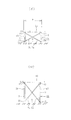
図3(イ)は上記太陽光パネル架台1に太陽光パネル重量と風圧力とを考慮した分布荷重wが作用した時のパネル受材2の撓みを説明する図である。
図3(イ)のように、分布荷重wが作用する全長Lの梁(パネル受材2)の2箇所の支点が端からそれぞれ等しい距離L1(すなわちL11=L12=L1)の位置(中間部の距離がL0)にある場合の梁の撓みは、中央での撓みをδ0、両端での撓みδ1をすると、
δ0=5wL0 4/384EI−wL1 2L0 2/16EI ・・・(4)
δ1=wL1 4/8EI−(wL0/24EI)×(L0 2−6L1 2)L1 ・・・(5)
となる。
中間部の距離L0=αL の係数αをパラメータ(横軸)として上記(4)、(5)式を計算して得られるδ0、δ1をグラフにすれば、図3(ロ)のようになる。この梁に生じる最大撓みが最も小さいのは、同グラフから明らかな通り、δ0の曲線とδ1の曲線とが交わった時であり、δ0=δ1 の時である。その時のαは0.554である。
したがって、この条件で最もパネル受材2の断面を最も小さくすることができるが、必ずしも厳格に最小断面にする必要はない。0.387Lから0.714Lの幅があっても、一定の鋼材使用量削減の効果が得られる。すなわち、たわみδ0がL0/150を超えると、ただ単に鋼材使用量が増えるだけでなく、風圧力に対して繰り返し大きなたわみが生じることになり、鋼材だけでなく、設置された太陽光パネルにも繰り返したわみが生じ、鋼材、太陽光パネル、および、その設置部材の耐久性が劣ることになる。従って、上部側の支柱と下部側の支柱間の長さが、たわみがL0/150以下になる0.387Lから0.714Lにする必要がある。
たわみδ0がL0/150以下であることが適切であることを、図11(イ)、(ロ)を参照して説明する。図11(イ)は、パネル受け材6の中央位置に、隣接する太陽光パネル10の隣接部がくることを示している。
複数の太陽光パネルを架台に設置する場合、隣接する太陽光パネル間に若干の隙間を設けるが、パネル受け材2にたわみが生じると、隣接する太陽光パネル10の端部が互いに接近するので、太陽光パネル同士に干渉が生じないような隙間(パネル間距離)を設ける必要がある。図11(ロ)のe'は、たわみδが生じた時の隙間(パネル間距離)を示している。
以下に述べるように、たわみは隣り合うパネル同士の干渉から最適パネル間距離で決まる。そして、パネル間距離が小さいほど支持部材の材料費を抑制できる。
実施例の場合、太陽光パネルの厚みtが50mm、中間部の距離L0が3324mm、パネル受け材6の高さHが100mmであることを考慮すると、図11(ロ)において、隣接するパネルの端点P1及びP2が近似的にパネル受け材2の中心点Oを中心に回転するとすると、たわみδがL0/150であると、干渉が生じないためのパネル間距離eは、詳細計算は省略するが、パネル受け材2の中心点Oからパネル下面までの高さ(H/2)が約50mmであることから約7mmとなる。これにボルト孔等による施工公差、各部材の熱膨張等を考慮して3mm加えると、最適パネル間距離は10mmとなる。このように、たわみ変形によるパネル同士の干渉を避けることが、最適パネル間距離を決める上で重要な要素であることを示す。
The upper and
FIG. 3A is a view for explaining the bending of the
As shown in FIG. 3 (a), the two fulcrums of the beam (panel receiving material 2) of the total length L on which the distributed load w acts are equal distances L 1 from the ends (that is, L 11 = L 12 = L 1 ). The deflection of the beam in the position (intermediate distance L 0 ) is δ 0 at the center and δ 1 at both ends.
δ 0 = 5 wL 0 4 / 384EI−wL 1 2 L 0 2 / 16EI (4)
δ 1 = wL 1 4 / 8EI− ( wL 0 / 24EI ) × (L 0 2 −6L 1 2 ) L 1 (5)
It becomes.
If δ 0 and δ 1 obtained by calculating the above equations (4) and (5) using the coefficient α of the intermediate portion distance L 0 = αL as a parameter (horizontal axis) are graphed, FIG. It becomes like this. As is clear from the graph, the maximum deflection generated in the beam is the smallest when the curve of δ 0 and the curve of δ 1 intersect, and when δ 0 = δ 1 . Α at that time is 0.554.
Therefore, although the cross section of the
The deflection [delta] 0 is L 0 / 0.99 appropriate or less, 11 (b) will be described with reference to (b). FIG. 11 (a) shows that the adjacent portion of the adjacent
When installing a plurality of solar panels on a gantry, a slight gap is provided between adjacent solar panels, but when the
As described below, the deflection is determined by the optimum inter-panel distance from the interference between adjacent panels. And the material cost of a supporting member can be suppressed, so that the distance between panels is small.
In the case of the example, considering that the thickness t of the solar panel is 50 mm, the distance L 0 between the intermediate portions is 3324 mm, and the height H of the
図4は具体的な太陽光パネル架台1の実施例を示す正面図、図5は同平面図、図6の(イ)は図4におけるC−C拡大断面図、(ロ)は図4におけるD−D拡大断面図である。
この太陽光パネル架台11は、100×50×3.2mmの不等辺の軽量山形鋼によるパネル受材12と、100×50×3.2mmの軽量溝形鋼による鉛直な上部側の支柱13及び下部側の支柱14とで構成された鉛直な一対の面状フレーム15を有する。前記一対の面状フレーム15はその面と直交する左右方向に間隔をあけて互いに平行に配され、各支柱13、14の下端が70×70×4.5mmの軽量山形鋼による固定部材18で基礎16に固定されている。各部材間の接合はすべてボルト接合であり、溶接接合部はない。また、パネル受材12と支柱3、4とのボルト接合部は2本以上(実施例では2本)のボルトによる剛接合的な接合であり、ブレース7a、7bと支柱3、4とは1本のボルトによるボルト接合である。
そして、前記一対の面状フレーム15間は、上部側及び下部側のそれぞれにおける左右の支柱間(支柱13、13間、及び支柱14、14間)に対角線状に取り付けられた交差する30×30×3.2mmの軽量山形鋼による2つのブレース17a、17bのみで連結されている。左右のパネル受材12間を直接連結する水平な連結部材は有さない。前記2つのブレース17a、17bは図5などに示すように、支柱13、14の架台長手方向の両面に分けて取り付けられている。
不等辺軽量山形鋼のパネル受材12は、図6(イ)、(ロ)に示すように、その横断面における上面が水平になる逆L字形に配されている。
そして、前記上部側の支柱13及び下部側の支柱14は、パネル受材12の長手方向の端からそれぞれ中央側に寄った位置においてパネル受材12にボルト接合により取り付けられるとともに、その取り付け位置は、パネル受材12の長さLに対してそれぞれ長さ方向の端から同じく0.223Lの位置(L1=(1−0.554)L/2=0.223L)にある。
各部の寸法を示すと、太陽光パネル10の設置傾斜角に等しいパネル受材12の傾斜角θは10°、パネル受材12の全長は6000mm(水平成分(図4にLで示した長さ)は5910mm)、中間部の長さは3324mm(その水平成分(図4にL0で示した長さ)は3274mm)、オーバーハング部の長さは1338mm(その水平成分(図4にL1で示した長さ)は1318mm)である。架台11の幅寸法Wは980mmである。上部側の支柱13の長さは1170mm、下部側の支柱14の長さは583mmである。
4 is a front view showing a specific embodiment of the
This
The pair of
As shown in FIGS. 6 (a) and 6 (b), the
The
In terms of the dimensions of each part, the inclination angle θ of the
本発明の太陽光パネル架台は、例えば1500mm×1000mm程度の太陽光パネルを2枚〜8枚程度並べて設置することを一応想定している(但し、このサイズ、及び枚数に限定されるものではない)。実施例の太陽光パネル架台11は図5に示すように、6枚の太陽光パネル10が設置される。太陽光パネル10は太陽光パネル架台11のパネル受材12に図7〜図9のように取り付けられる。図7は太陽光パネル架台11に太陽光パネル10を設置した状態の要部の平面図、図8は図7の要部のJ−J拡大断面図、図9は図8の右側面図である。
太陽光パネル10は、太陽電池部分10aの周囲を支持する矩形のフレーム10bの部分で例えば、図8のように取り付けられる。図示例では、不等辺軽量山形鋼のパネル受材12に上面部に、太陽光パネル10のアルミのフレーム10bに設けた取付孔10cに合せたボルト挿通孔12aをあけ、ボルト21を取付孔10c、ボルト挿通孔12aに通しナット22を螺合させ締め付けて、フレーム10bをパネル受材12に固定して、太陽光パネル10を太陽光パネル架台11に固定する。
この実施例ではパネル受材12がL字形鋼材(不等辺軽量山形鋼)であり、上面が水平になる逆L字形に配されているので、図9に示す通り、パネル受材12の下方側はオープンになり、太陽光パネル10を太陽光パネル架台11上に載せた状態で、パネル下面で太陽光パネル10のフレーム10bと架台11のパネル受材12とをボルトで結合させる作業の際、例えばインパクトレンチによってボルト締め可能なスペースを確保することができ、作業性が良好である。
For example, the solar panel mount of the present invention is assumed to be installed by arranging about 2 to 8 solar panels of about 1500 mm × 1000 mm side by side (however, it is not limited to this size and number). ). As shown in FIG. 5, the
The
In this embodiment, the
図4〜図9の実施例の太陽光パネル架台11を構成する各部材は、一般的な断面形状の軽量形鋼であるが、それらの部材に代えて、図10A(イ)〜(ニ)や図10B(ホ)〜(チ)のように軽量形鋼の端縁部を内側に折り曲げた断面形状の部材を用いることもできる。
図10A(イ)の部材31は、リップ31aの付いた不等辺軽量山形鋼のリップ31aの端縁部を内側に折り曲げた変形リップ付き不等辺軽量山形鋼31である。
図10A(ロ)の部材32は、軽量溝形鋼のフランジ32aの端縁部を内側に折り曲げた変形軽量溝形鋼である。
図10A(ハ)の部材33は、軽量C形鋼のリップ33aの端縁部を内側に折り曲げた変形軽量C形鋼である。
図10A(ニ)の部材34は、軽量山形鋼の2つの辺34aの端縁部をそれぞれ内側に折り曲げた変形軽量山形鋼である。
図10B(ホ)の部材35は、軽量溝形鋼のフランジ35aの端縁部を小さくかつフランジ内側面に密着するように内側に折り曲げた変形軽量溝形鋼である。
図10B(ヘ)の部材36は、リップを若干長くした軽量C形鋼の前記リップ36aの中間位置よりやや先端側位置を内側にかつリップ内側面に密着するように折り曲げた変形軽量C形鋼である。
図10B(ト)の部材37は、リップを大幅に長くした軽量C形鋼の前記長いリップ37aの中間位置よりリップ付け根寄りの位置を内側に直角に折り曲げた変形軽量C形鋼である。
図10B(チ)の部材38は、軽量山形鋼の2つの辺38aの端縁部をそれぞれ内側に辺38aの内側面に密着するように折り曲げた変形軽量山形鋼である。
上記のように、軽量形鋼の端縁部を内側に折り曲げることで、赤錆の発生し易い端面(エッジ)が外観として表れず、赤錆発生時の外観不良を避けることができる。
Each member constituting the
The
The
The
The
The
The
The
The
As described above, by bending the edge portion of the light-weight shaped steel inward, the end face (edge) where red rust is likely to occur does not appear as the appearance, and poor appearance when red rust occurs can be avoided.
1、11 太陽光パネル架台
2、12 パネル受材
12a ボルト挿通孔
3、13 上部側の支柱
4、14 下部側の支柱
5、15 面状フレーム
6 基礎
7a、7b ブレース
17a、17b ブレース
10 太陽光パネル
10b (太陽光パネルの)フレーム
10c 取付孔
21 ボルト
22 ナット
L パネル受材の全長(又はその水平成分)
L0 パネル受材の支柱間(中間部)の距離(又はその水平成分)
L1(L11、L12) パネル受材の端から支柱までの距離(又はその水平成分)
α (L0=αL における)係数
DESCRIPTION OF
Between L 0 panel receiving material of the strut distance (intermediate portion) (or horizontal component thereof)
L 1 (L 11 , L 12 ) Distance from the end of the panel receiving material to the column (or its horizontal component)
α coefficient (in L 0 = αL)
Claims (3)
一対の前記面状フレームをその面と直交する左右方向に間隔をあけて互いに平行に配し、前記一対の面状フレーム間は、上部側及び下部側のそれぞれにおける左右の支柱間に対角線状に取り付けられた交差する2つのブレースのみで連結され、
前記上部側の支柱及び下部側の支柱は、パネル受材の長手方向両端からそれぞれ中央側に寄った位置においてパネル受材に取り付けられるとともに、その取り付け位置は、パネル受材の全長Lに対して上部側の支柱と下部側の支柱間の長さL 0 が、パネル受材の長手方向中央でのたわみδ 0 がL 0 /150以下となるような位置として求めた、0.387Lから0.714Lの範囲内にあり、かつ、それぞれ先端側から、ほぼ対称的な位置であることを特徴とする太陽光パネル架台。 An inclined panel receiving material for installing a solar panel at a predetermined angle, a vertical upper column supporting an inclined upper side of the inclined panel receiving material, and a vertical supporting an inclined lower side of the panel receiving material A vertical plane frame is constructed with the lower support column,
A pair of the planar frames are arranged in parallel to each other with a space in the left-right direction orthogonal to the plane, and the pair of planar frames are diagonally formed between the left and right support columns on the upper side and the lower side, respectively. Connected only by two attached braces,
The upper support column and the lower support column are attached to the panel receiver at positions close to the center side from both longitudinal ends of the panel receiver, and the mounting position is relative to the total length L of the panel receiver. length L 0 between the upper side of the strut and the lower strut deflection [delta] 0 in the longitudinal center of the panel receiving material is determined as a position such that L 0 / 0.99 or less, 0 to 0.387L. in the range of 714l, and, from the respective distal end side, solar panels stand, which is a substantially symmetrical position.
Priority Applications (1)
| Application Number | Priority Date | Filing Date | Title |
|---|---|---|---|
| JP2012082293A JP5991512B2 (en) | 2011-03-31 | 2012-03-30 | Solar panel mount |
Applications Claiming Priority (3)
| Application Number | Priority Date | Filing Date | Title |
|---|---|---|---|
| JP2011079187 | 2011-03-31 | ||
| JP2011079187 | 2011-03-31 | ||
| JP2012082293A JP5991512B2 (en) | 2011-03-31 | 2012-03-30 | Solar panel mount |
Publications (2)
| Publication Number | Publication Date |
|---|---|
| JP2012215067A JP2012215067A (en) | 2012-11-08 |
| JP5991512B2 true JP5991512B2 (en) | 2016-09-14 |
Family
ID=47268045
Family Applications (1)
| Application Number | Title | Priority Date | Filing Date |
|---|---|---|---|
| JP2012082293A Active JP5991512B2 (en) | 2011-03-31 | 2012-03-30 | Solar panel mount |
Country Status (1)
| Country | Link |
|---|---|
| JP (1) | JP5991512B2 (en) |
Families Citing this family (7)
| Publication number | Priority date | Publication date | Assignee | Title |
|---|---|---|---|---|
| JP6104673B2 (en) * | 2013-03-29 | 2017-03-29 | 株式会社東芝 | Solar cell module |
| JP5724136B2 (en) * | 2013-04-03 | 2015-05-27 | 株式会社Mario Del Mare | Mounting structure |
| CN103441158A (en) * | 2013-08-27 | 2013-12-11 | 江苏尚特光伏科技有限公司 | C-type steel assembly |
| CN103413849A (en) * | 2013-08-28 | 2013-11-27 | 江苏尚特光伏科技有限公司 | Solar photovoltaic panel device |
| JP6346755B2 (en) * | 2014-02-25 | 2018-06-20 | 株式会社サンレール | Solar power panel |
| CN105680776B (en) * | 2016-04-06 | 2018-07-10 | 中国能源建设集团云南省电力设计院有限公司 | A kind of XYZ three-dimensionals install adjustable photovoltaic support |
| JP2017077167A (en) * | 2016-11-21 | 2017-04-20 | 株式会社東芝 | Solar cell module |
Family Cites Families (6)
| Publication number | Priority date | Publication date | Assignee | Title |
|---|---|---|---|---|
| JPH1061099A (en) * | 1996-08-23 | 1998-03-03 | Natl House Ind Co Ltd | Long-sized member for construction |
| JP2002273521A (en) * | 2001-03-19 | 2002-09-25 | Okuchi Kensan Kk | Lightweight shape steel and method for manufacturing the same |
| JP2006210613A (en) * | 2005-01-27 | 2006-08-10 | Kyocera Corp | Solar power generator |
| JP5106895B2 (en) * | 2007-03-23 | 2012-12-26 | 京セラ株式会社 | Solar array |
| JP3141450U (en) * | 2008-01-18 | 2008-05-08 | 朋 安田 | Solar cell module mounting structure |
| JP5312387B2 (en) * | 2010-03-26 | 2013-10-09 | 三菱電機株式会社 | Support platform for solar array |
-
2012
- 2012-03-30 JP JP2012082293A patent/JP5991512B2/en active Active
Also Published As
| Publication number | Publication date |
|---|---|
| JP2012215067A (en) | 2012-11-08 |
Similar Documents
| Publication | Publication Date | Title |
|---|---|---|
| JP5991512B2 (en) | Solar panel mount | |
| JP6026131B2 (en) | Functional panel support stand | |
| JP2014034830A (en) | Installation frame for solar battery panel and installation method for solar battery panel | |
| JP5365937B2 (en) | Solar panel mounting device | |
| JP6150640B2 (en) | Solar panel mount | |
| JP2013055263A (en) | Solar panel frame | |
| JP2014148822A (en) | Installation device of solar battery array to folded-plate roof | |
| US20140318046A1 (en) | Purlin construction for roof structures | |
| JP5967438B2 (en) | Brace seismic reinforcement structure | |
| JP5472535B2 (en) | Panel support base | |
| JP6196474B2 (en) | Solar panel installation structure and installation method | |
| JP6366171B2 (en) | Roof support equipment | |
| JP2016037730A (en) | Extrusion section | |
| JP7033360B1 (en) | Stand for solar panels | |
| CN113789857B (en) | Beam column connecting piece for light steel structure based on nut assembly | |
| JP5301700B1 (en) | Attached units and unit buildings | |
| JP5930690B2 (en) | Functional panel support stand | |
| JP2013064276A (en) | Gable roof building | |
| JP5788470B2 (en) | Solar cell module mounting base | |
| JP2013053479A (en) | Solar panel frame | |
| KR101423450B1 (en) | Panel support mounting | |
| CN210797875U (en) | Connecting piece of H-shaped beam column with light steel structure | |
| JP5844102B2 (en) | Roof structure | |
| JP5944128B2 (en) | Roof structure | |
| JP2014101691A (en) | Support structure of solar cell module, frame for solar cell module using the support structure, and photovoltaic power generation system using the frame |
Legal Events
| Date | Code | Title | Description |
|---|---|---|---|
| A621 | Written request for application examination |
Free format text: JAPANESE INTERMEDIATE CODE: A621 Effective date: 20150227 |
|
| A977 | Report on retrieval |
Free format text: JAPANESE INTERMEDIATE CODE: A971007 Effective date: 20151202 |
|
| A131 | Notification of reasons for refusal |
Free format text: JAPANESE INTERMEDIATE CODE: A131 Effective date: 20151208 |
|
| A521 | Written amendment |
Free format text: JAPANESE INTERMEDIATE CODE: A523 Effective date: 20160208 |
|
| TRDD | Decision of grant or rejection written | ||
| A01 | Written decision to grant a patent or to grant a registration (utility model) |
Free format text: JAPANESE INTERMEDIATE CODE: A01 Effective date: 20160802 |
|
| A61 | First payment of annual fees (during grant procedure) |
Free format text: JAPANESE INTERMEDIATE CODE: A61 Effective date: 20160803 |
|
| R150 | Certificate of patent or registration of utility model |
Ref document number: 5991512 Country of ref document: JP Free format text: JAPANESE INTERMEDIATE CODE: R150 |