JP5988391B2 - Unmanned vehicle and system - Google Patents
Unmanned vehicle and system Download PDFInfo
- Publication number
- JP5988391B2 JP5988391B2 JP2013543164A JP2013543164A JP5988391B2 JP 5988391 B2 JP5988391 B2 JP 5988391B2 JP 2013543164 A JP2013543164 A JP 2013543164A JP 2013543164 A JP2013543164 A JP 2013543164A JP 5988391 B2 JP5988391 B2 JP 5988391B2
- Authority
- JP
- Japan
- Prior art keywords
- unmanned vehicle
- vehicle
- energy
- unmanned
- beam source
- Prior art date
- Legal status (The legal status is an assumption and is not a legal conclusion. Google has not performed a legal analysis and makes no representation as to the accuracy of the status listed.)
- Active
Links
- 238000004146 energy storage Methods 0.000 claims description 24
- 238000013459 approach Methods 0.000 claims description 7
- 238000005259 measurement Methods 0.000 claims description 7
- 230000000007 visual effect Effects 0.000 claims description 6
- 238000010586 diagram Methods 0.000 description 9
- 238000012423 maintenance Methods 0.000 description 7
- 230000006870 function Effects 0.000 description 5
- 230000003287 optical effect Effects 0.000 description 5
- 230000008859 change Effects 0.000 description 4
- 238000004891 communication Methods 0.000 description 3
- 238000006243 chemical reaction Methods 0.000 description 2
- 238000007726 management method Methods 0.000 description 2
- 238000012545 processing Methods 0.000 description 2
- 230000008439 repair process Effects 0.000 description 2
- XLYOFNOQVPJJNP-UHFFFAOYSA-N water Substances O XLYOFNOQVPJJNP-UHFFFAOYSA-N 0.000 description 2
- 230000007423 decrease Effects 0.000 description 1
- 230000007812 deficiency Effects 0.000 description 1
- 230000001066 destructive effect Effects 0.000 description 1
- 239000000446 fuel Substances 0.000 description 1
- 229910052736 halogen Inorganic materials 0.000 description 1
- 150000002367 halogens Chemical class 0.000 description 1
- 238000005338 heat storage Methods 0.000 description 1
- 230000003993 interaction Effects 0.000 description 1
- 230000004807 localization Effects 0.000 description 1
- 238000004519 manufacturing process Methods 0.000 description 1
- 230000007246 mechanism Effects 0.000 description 1
- 238000000034 method Methods 0.000 description 1
- 239000003973 paint Substances 0.000 description 1
- 239000002096 quantum dot Substances 0.000 description 1
- 238000000926 separation method Methods 0.000 description 1
- 230000000087 stabilizing effect Effects 0.000 description 1
- 239000000126 substance Substances 0.000 description 1
- 230000007723 transport mechanism Effects 0.000 description 1
Images


Classifications
-
- G—PHYSICS
- G05—CONTROLLING; REGULATING
- G05D—SYSTEMS FOR CONTROLLING OR REGULATING NON-ELECTRIC VARIABLES
- G05D1/00—Control of position, course or altitude of land, water, air, or space vehicles, e.g. automatic pilot
- G05D1/10—Simultaneous control of position or course in three dimensions
- G05D1/101—Simultaneous control of position or course in three dimensions specially adapted for aircraft
-
- B—PERFORMING OPERATIONS; TRANSPORTING
- B64—AIRCRAFT; AVIATION; COSMONAUTICS
- B64U—UNMANNED AERIAL VEHICLES [UAV]; EQUIPMENT THEREFOR
- B64U50/00—Propulsion; Power supply
- B64U50/30—Supply or distribution of electrical power
- B64U50/34—In-flight charging
- B64U50/35—In-flight charging by wireless transmission, e.g. by induction
-
- B—PERFORMING OPERATIONS; TRANSPORTING
- B64—AIRCRAFT; AVIATION; COSMONAUTICS
- B64U—UNMANNED AERIAL VEHICLES [UAV]; EQUIPMENT THEREFOR
- B64U10/00—Type of UAV
- B64U10/10—Rotorcrafts
- B64U10/13—Flying platforms
-
- B—PERFORMING OPERATIONS; TRANSPORTING
- B64—AIRCRAFT; AVIATION; COSMONAUTICS
- B64U—UNMANNED AERIAL VEHICLES [UAV]; EQUIPMENT THEREFOR
- B64U10/00—Type of UAV
- B64U10/10—Rotorcrafts
- B64U10/13—Flying platforms
- B64U10/14—Flying platforms with four distinct rotor axes, e.g. quadcopters
-
- B—PERFORMING OPERATIONS; TRANSPORTING
- B64—AIRCRAFT; AVIATION; COSMONAUTICS
- B64U—UNMANNED AERIAL VEHICLES [UAV]; EQUIPMENT THEREFOR
- B64U2201/00—UAVs characterised by their flight controls
- B64U2201/10—UAVs characterised by their flight controls autonomous, i.e. by navigating independently from ground or air stations, e.g. by using inertial navigation systems [INS]
- B64U2201/104—UAVs characterised by their flight controls autonomous, i.e. by navigating independently from ground or air stations, e.g. by using inertial navigation systems [INS] using satellite radio beacon positioning systems, e.g. GPS
-
- B—PERFORMING OPERATIONS; TRANSPORTING
- B64—AIRCRAFT; AVIATION; COSMONAUTICS
- B64U—UNMANNED AERIAL VEHICLES [UAV]; EQUIPMENT THEREFOR
- B64U2201/00—UAVs characterised by their flight controls
- B64U2201/20—Remote controls
-
- B—PERFORMING OPERATIONS; TRANSPORTING
- B64—AIRCRAFT; AVIATION; COSMONAUTICS
- B64U—UNMANNED AERIAL VEHICLES [UAV]; EQUIPMENT THEREFOR
- B64U50/00—Propulsion; Power supply
- B64U50/10—Propulsion
- B64U50/19—Propulsion using electrically powered motors
-
- B—PERFORMING OPERATIONS; TRANSPORTING
- B64—AIRCRAFT; AVIATION; COSMONAUTICS
- B64U—UNMANNED AERIAL VEHICLES [UAV]; EQUIPMENT THEREFOR
- B64U50/00—Propulsion; Power supply
- B64U50/30—Supply or distribution of electrical power
- B64U50/31—Supply or distribution of electrical power generated by photovoltaics
-
- B—PERFORMING OPERATIONS; TRANSPORTING
- B64—AIRCRAFT; AVIATION; COSMONAUTICS
- B64U—UNMANNED AERIAL VEHICLES [UAV]; EQUIPMENT THEREFOR
- B64U50/00—Propulsion; Power supply
- B64U50/30—Supply or distribution of electrical power
- B64U50/34—In-flight charging
Description
本開示の分野は、概して無人ビークルに関するものであり、特に被給電無人空中ビークルに関するものである。無人ビークルは、運転エネルギーを必要とし、定期的に燃料を補給し、修理し、保守して運転を継続する。無人ビークルの可用性を高めるために、搬入/搬出、燃料補給、メンテナンス、及び修理に要する時間を最小限に抑えることが望ましい。ビーム給電システムによって、ビークルが基地に戻って燃料補給する、または充電する必要を無くすことができる。更に、無人空中ビークル(UAV)の場合、ビーム給電システムによって、着陸/離陸回数を減らすこともできる。したがって、ビーム給電システムによって、UAVのメンテナンス及び修理の頻度を減らすことができる。 The field of the disclosure relates generally to unmanned vehicles, and more particularly to powered unmanned aerial vehicles. Unmanned vehicles require operating energy and are regularly refueled, repaired, maintained, and continued to operate. In order to increase the availability of unmanned vehicles, it is desirable to minimize the time required for loading / unloading, refueling, maintenance and repair. The beam feeding system can eliminate the need for the vehicle to return to the base to refuel or charge. Furthermore, in the case of an unmanned aerial vehicle (UAV), the number of landings / takeoffs can be reduced by a beam feeding system. Therefore, the frequency of maintenance and repair of the UAV can be reduced by the beam feeding system.
しかしながら、公知のビーム給電システムの使用は限定されている。少なくとも幾つかの公知のビーム給電システムは、無人ビークルが移動している状態でビームを無人ビークルに誘導し、従ってビームを移動させて、ビークルの移動に追従させる。ビームステアリングには普通、光学システムまたは機械的に操作するマイクロ波システムの正確で複雑な可動構成品群が必要であり、フェーズドアレーマイクロ波システムの複雑で高価な電子機器が必要である。このようなステアリングシステムによって、コスト、重量、脆弱性、及び複雑さがビーム給電システムに加わる。 However, the use of known beam feeding systems is limited. At least some known beam feeding systems guide the beam to the unmanned vehicle while the unmanned vehicle is moving, thus moving the beam to follow the movement of the vehicle. Beam steering usually requires precise and complex moving components of an optical system or mechanically operated microwave system, and the complex and expensive electronics of a phased array microwave system. Such a steering system adds cost, weight, vulnerability and complexity to the beam feed system.
少なくとも幾つかの他の公知のビーム給電システムは、固定ビーム源と、一連のワイヤまたはレールに接続されて、確実にビームの内部に位置し続けるように動きを拘束されたビークルとを含む。しかしながら、ビークルは、ビームから離れる方向に移動することができないので、このようなシステムの使用は限定される。他の公知のシステムは、固定ビーム源を用いて、ワイヤまたはレールで物理的に繋がれることのないビークルを照射する。しかしながら、このようなシステムでは、ビークルは、推進構造、すなわち所定の光学的及び空気力学的構造を有し、これにより、ビークルがビームの中心に確実に位置し続ける。この場合も同じように、このようなシステムは、ビークルがビームの外側を移動することができない、またはビームの外側で運転することができないので限定される。 At least some other known beam feeding systems include a fixed beam source and a vehicle that is connected to a series of wires or rails and is constrained to remain positioned within the beam. However, the use of such a system is limited because the vehicle cannot move away from the beam. Other known systems use fixed beam sources to irradiate vehicles that are not physically connected by wires or rails. However, in such a system, the vehicle has a propulsion structure, i.e. a predetermined optical and aerodynamic structure, which ensures that the vehicle remains in the center of the beam. Again, such a system is limited because the vehicle cannot move outside the beam or cannot operate outside the beam.
1つの実施形態では、無人ビークルが提供される。前記無人ビークルは、前記無人ビークルをビーム源から放出されるエネルギービームに対して誘導するように構成されたナビゲーションシステムと、エネルギーを前記ビームから受け取るように構成された電力受給器と、受け取ったエネルギーを貯蔵して前記無人ビークルに選択的に給電するために利用するように構成されたエネルギー貯蔵システムとを含む。 In one embodiment, an unmanned vehicle is provided. The unmanned vehicle includes a navigation system configured to guide the unmanned vehicle relative to an energy beam emitted from a beam source, a power receiver configured to receive energy from the beam, and received energy. And an energy storage system configured to be utilized to selectively power the unmanned vehicle.
別の実施形態では、ビークルシステムが提供される。前記ビークルシステムは、エネルギービームを放出するように構成されたビーム源と、無人ビークルとを備え、該無人ビークルは、ナビゲーションシステムと、電力受給器と、エネルギー貯蔵システムとを備え、前記ナビゲーションシステムは、前記無人ビークルを前記ビームに対して位置決めするように構成され、前記電力受給器は、エネルギーを前記ビームから受け取るように構成され、前記エネルギー貯蔵システムは、前記受け取ったエネルギーを貯蔵して前記無人ビークルに給電するために利用するように構成された。 In another embodiment, a vehicle system is provided. The vehicle system comprises a beam source configured to emit an energy beam and an unmanned vehicle, the unmanned vehicle comprising a navigation system, a power receiver, and an energy storage system, the navigation system comprising: The unmanned vehicle is configured to position the unmanned vehicle with respect to the beam, the power receiver is configured to receive energy from the beam, and the energy storage system stores the received energy to store the unmanned vehicle. It was configured to be used to power the vehicle.
本明細書において記載されるシステムは、公知のビーム給電システムの不具合のうちの少なくとも幾つかを解決する。更に詳細には、本明細書において記載されるシステムは、公知のビーム給電システムに関連するコスト、重量、複雑さ、及びメンテナンスに対する要求を軽減するビーム給電システムを提供する。更に、本明細書において記載されるシステムはまた、複数の異なるプラットフォーム、および複数の異なる環境に取り付け、操作することができるビーム源を提供する。 The system described herein solves at least some of the deficiencies of known beam feeding systems. More particularly, the system described herein provides a beam feeding system that reduces the cost, weight, complexity, and maintenance requirements associated with known beam feeding systems. In addition, the systems described herein also provide beam sources that can be installed and operated on multiple different platforms and multiple different environments.
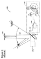
図1は、例示的な公知のビーム給電システム100の模式図である。例示的な実施形態では、ビーム給電システム100は、ビーム源102と、ビーム104と、無人ビークル106と、ステアリングミラー108と、制御システム110とを含む。制御システム110は、位置センサ112と、コントローラ114と、オペレータ制御インターフェース116とを含む。使用状態では、制御システム110は、ステアリングミラー108を操作して、ビーム源102から放出されるビーム104の相対的方向を変化させる。位置センサ112は、無人ビークル106の位置を検出することができ、ステアリングミラー108を操作して、ビーム104を無人ビークル106に向かって放出することができる。ステアリングミラー108はビーム104を旋回させて、無人ビークル106を或る角度範囲で追跡するだけでなく、ビーム104の焦点距離を調整して、無人ビークル106とビーム源102との間の離間距離が変化するときに、正しい強度を無人ビークル106上で保持することができる。特に、ビーム給電システム100は、正しく動作するために極めて高性能の電子部品及び機械部品を必要とする。
FIG. 1 is a schematic diagram of an exemplary known
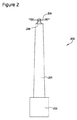
図2は、例示的なビーム給電システム200の模式図である。例示的な実施形態では、ビーム給電システム200は、ビーム源202と、ビーム204と、無人ビークル206とを含む。例示的な実施形態では、無人ビークル206は無人飛行体(UAV)である。別の実施形態では、無人ビークル206は、垂直離着陸(VTOL)UAVである。別の構成として、無人ビークル206は、本明細書に記載の通りに機能することができる任意の種類の無人ビークルとすることができ、種類の無人ビークルとして、これらには限定されないが、飛行船、固定翼UAV、地上ビークル、または水上ビークル(図示せず)を挙げることができる。
FIG. 2 is a schematic diagram of an exemplary
例示的な実施形態では、ビーム源202はビーム204を放出する。ビーム204はエネルギービームである。例示的な実施形態では、ビーム源202は所定の位置に固定されて、ビーム源202及びビーム204が無人ビークル206に追従しない、または無人ビークル206に合わせて移動しない。更に、例示的な実施形態では、ビーム源202は固定焦点距離を有する。別の実施形態では、ビーム204の方向は調整可能であり、および/またはビーム源202は、ビーム204を有限距離にまで延長できる、または有限距離に収束させることができるレンズまたは凹ミラーのような少なくとも1つの光学素子を含むことができる。
In the exemplary embodiment,
例示的な実施形態では、ビーム源202はエネルギー源から受け取るエネルギーを比較的狭幅の電磁波ビームに変換し、この電磁波ビームは、無人ビークル206による接近に適する一定方向に放出される。1つの実施形態では、ビーム源202は、電気エネルギー源に接続される。別の実施形態では、任意の適切な電源を用いてビーム源202に給電することができる。
In the exemplary embodiment,
例示的な実施形態では、ビーム源202を上方に向けて、ビーム204を略垂直方向に放出する。別の構成として、ビーム源202は選択的に調整可能であることにより、ビーム204を、ビーム給電システム200が本明細書に記載される通りに機能することができるように任意の方向に放出することができる。更に、例示的な実施形態では、ビーム源202は、静止地上プラットフォームに取り付けられる。別の実施形態では、ビーム源202は、構造物または移動ビークルに接続される。
In the exemplary embodiment,
異なる態様では、異なる種類の電磁エネルギーをビーム源202から放出させて、無人ビークル206に給電する。各態様では、放出される電磁エネルギーの種類は、以下に更に詳細に説明するように、無人ビークル206が受け取り、貯蔵するように構成された電磁エネルギーの種類に一致する。したがって、例示的な実施形態では、無人ビークル206は、ビーム源202から放出される電磁エネルギーを受け取る電力受給器208を含む。例えば、1つの実施形態では、電力受給器208は光起電力型受光素子である。
In different aspects, different types of electromagnetic energy are emitted from the
1つの実施形態では、ビーム源202は、無人ビークル206に搭載される電力受給器208の光起電力素子のバンドギャップに略一致するように調整されるレーザ光源または別の単色光源を用いる。光源は、電力への光起電力変換効率を容易に最大化するように選択することができる。別の構成として、光源は、ビーム輝度を最適化するように選択することができるので、ビームが狭幅及び強度を保持する範囲を容易に最大化することができる。
In one embodiment, the
例示的な実施形態では、ビーム源202は、単色光源を用いて送信される。この技術分野の当業者であれば、他の実施形態では、他の種類のビーム源を用いることができることを理解できるであろう。例えば、1つの別の実施形態では、広帯域スペクトルの可視光ビーム(ハロゲンランプまたはサーチライトのような)を用いる。他の実施形態では、マイクロ波ビームを用いて、エンドツーエンドの電力変換効率を最大にする、またはビーム給電システム200の可観測性を低くすることができる。
In the exemplary embodiment,
ビーム源202は、ビーム204を収束させて高強度部分を、ビーム源202から一定の有限距離の位置に形成する。1つの別の実施形態では、ビーム源202は、複数の個別ビーム源を含み、これらのビーム源を配置し、向きを設定することにより、これらのビーム源の個々のビームを交差させて、高強度部分を、ビーム源202から一定の有限距離の位置に形成する。更に、1つの実施形態では、ビーム源202は高強度部分を、ビーム204の断面が、電力受給器208のレイアウトに略一致する位置に形成する。例えば、無人ビークル206内の電力受給器208が、矩形の光起電力アレイである場合、ビーム源202は、略矩形の形状を持つビーム204を、ビーム源の高強度部分の近傍に投射することができる。別の構成として、電力受給器208が円形アレイを有する場合、ビーム源は、略円形の形状を持つビーム204を、ビーム源の高強度部分の近傍に投射するように構成することができる。例示的な実施形態では、以下に更に詳細に説明するように、無人ビークル206は、電力受給器208を、ビーム源202の高強度部分に位置合わせするように構成された。
The
図3は、図2に示すビーム給電システム200に使用することができる例示的なビーム源202の模式図である。例示的な実施形態では、ビーム源202は、位置特定システム220と、位置基準システム222と、接近作動システム224とを含む。
FIG. 3 is a schematic diagram of an
例示的な実施形態では、位置特定システム220によって、無人ビークル206は、無人ビークル206がビーム源202から或る距離に位置するときにビーム204の位置を特定し易くなる。1つの別の実施形態では、位置特定システム220は、ビーム源202の位置の特定を可能にする全地球測位システム(GPS)と、ビーム源202の位置を無人ビークル206に送信する無線機とを含む。別の構成として、位置特定システム220は、任意の他の位置特定システムを含むことができ、他の位置特定システムによってビーム給電システム200は、本明細書において記載される通りに機能することができる。
In the exemplary embodiment,
例示的な実施形態では、ビーム源202は、更に、位置基準システム222を含み、位置基準システム222によって無人ビークル206は、一旦、無人ビークル206がビーム源202の所定の近傍内に位置すると、無人ビークル自体がビーム204の中心に位置し易くなる。1つの例示的な実施形態では、位置基準システム222は、差分GPS(DGPS)のようなローカル基準信号を送信する。別の構成として、位置基準システム222は、無人ビークル206に搭載されるカメラで観測することができる一連のオブジェクト特徴点(図示せず)を含むことができる。
In the exemplary embodiment,
ビーム源202は、更に、無人ビークル206がビーム源202の所定の近傍内に位置するときに接近作動システム224を作動させる接近作動システム224を含む。したがって、接近作動システム224は、無人ビークル206がビーム204から所定距離内に位置しているかどうかを判断することができる。接近作動システム224を用いて、ビーム源202は、ビーム源202に対する無人ビークル206の位置によって異なるように、選択的に作動状態になることができる。別の構成として、非作動状態になるのではなく、ビーム源202は、無人ビークル206が所定の近傍の外部にあるときに電力低減動作モードに切り替わることができる。1つの実施形態では、接近作動システム224は、無人ビークル206から放出される音を認識する音響センサを含む。別の構成として、接近作動システム224は、無人ビークル206の出現を認識する視覚センサ及び/又は位置データを無人ビークル206から受信する無線機を含むことができる。
The
図4は、図2に示すビーム給電システム200に用いることができる例示的な無人ビークル206の模式図である。例示的な実施形態では、無人ビークル206は、垂直離着陸(VTOL)無人飛行体(UAV)である。しかしながら、別の実施形態では、無人ビークル206は、異なる種類のUAV、地上ビークル、または水上ビークルとすることができる。無人ビークル206がUAVである少なくとも幾つかの実施形態の場合、無人ビークル206は、ビーム204内でホバリング状態に飛行することができる。1つの実施形態では、無人ビークル206は固定翼UAVであり、この固定翼UAVは、十分高い推力重量比を有するので、無人ビークル206は垂直方向に上昇し、無人ビークルのプロペラの推力による「吊り」で高度をほぼ維持することにより、ビーム204に対して略一定の位置に留まることができる。
FIG. 4 is a schematic diagram of an exemplary
例示的な実施形態では、無人ビークル206は、ビークル推進システム240と、制御システム242と、電力受給器208と、エネルギー貯蔵システム244と、1つ以上の積載システム246と、ナビゲーションシステム248と、位置制御システム250とを含み、これらの構成要素の各々は、以下に更に詳細に説明される。本明細書において記載される多くの実施形態では、相互作用が無人ビークル206とビーム204との間で行なわれるが、この技術分野の当業者であれば、本明細書において記載される無人ビークル206は、更に、ビーム源を利用することができない場合に飛び立ち、動作することができることを理解できるであろう。
In the exemplary embodiment,
ビークル推進システム240を用いて、無人ビークル206の相対位置を変更する、または保持する。例示的な実施形態では、ビークル推進システム240は、少なくとも1つの位置決め装置254に接続される少なくとも1つのモータ252を含む。例示的な実施形態では、位置決め装置254はプロペラである。別の構成として、位置決め装置254は、無人ビークル206の位置を変更することができる任意の装置とすることができ、任意の装置として、これらには限定されないが、ホイール、トレッド機構、翼、及び/又はビークル推進システム240及び無人ビークル206を本明細書に記載の通りに機能させることができる任意の装置を挙げることができる。
A
制御システム242は、ビークル推進システム240の動作を制御する。無人ビークル206の相対位置を変更する、または保持するために、制御システム242は、モータ252と通信して、位置決め装置254を動作させる。例示的な実施形態では、制御システム242は、電力管理/供給(PMAD)システム256を含み、PMADシステム256は、電力をビークル推進システム240、電力受給器208、エネルギー貯蔵システム244、積載システム246、ナビゲーションシステム248、及び/又は位置制御システム250に割り当て、給電して、無人ビークル206を運行する。PMADシステム256は、更に、電力受給器208から無人ビークル206の他の構成要素群に出力される電圧及び/又は電流を一定に維持し、これにより、他の構成要素群を電圧変動または電力サージから保護する。制御システム242は、更に、命令群258をナビゲーションシステム248及び/又は位置制御システム250から受信することができ、受信すると、ビークル推進システム240に指示して、これらの命令に従って動作させることができる。
The
電力受給器208は、エネルギーをビーム204から受けて、無人ビークル206に給電するために使用されるエネルギー形態に変換する。例えば、例示的な実施形態では、電力受給器208は、ビーム204からのエネルギーを電力に変換する。1つの態様では、ビーム源202は、レーザ光源または他の可視光源であり、電力受給器208は、レーザ光源または他の可視光源からの電力を受光して電力生成する光起電力アレイである。別の態様では、ビーム源202はマイクロ波を放出し、電力受給器208はレクテナ素子である。別の実施形態は、これらには限定されないが、量子ドット太陽電池を含む任意の適切な電力受給器208、または無人ビークル206の内部の熱エンジンに給電する熱エネルギー受給器を含むことができる。例えば、1つの実施形態では、熱エネルギー受給器は、エネルギーを熱として熱エネルギー貯蔵システムに貯蔵することができる。したがって、異なる実施形態では、電力受給器208は、所望の形態のエネルギーをビーム源202から受け取り、ビーム204からのエネルギーを、無人ビークル206に給電することにより、無人ビークル206を本明細書に記載の通りに機能させることができる所望の形態のエネルギーに変換することができる。
The
例示的な実施形態では、無人ビークル206はエネルギー貯蔵システム244を含む。エネルギー貯蔵システム244は、エネルギーを供給して、無人ビークル206がビーム204の外部を移動することを可能にする。したがって、エネルギー貯蔵システム244によって無人ビークル206は、発射地点または配備地点からビーム204に向かって、またはビーム204から離れるように移動することができる。例示的な実施形態では、エネルギー貯蔵システム244は、電力受給器208に接続されており、無人ビークル206がビーム204内に位置しているときに、電力受給器208が受け取ったエネルギーを利用して充電可能である。更に、無人ビークル206がビーム204内に位置している間に、エネルギー貯蔵システム244を用いて電力急増に対する要求(すなわち、ビーム204が普通に供給する電力よりも大きい電力に対する瞬時的な要求)を満たすことができる、または無人ビークル206の運行をビーム204が中断している間に継続することができる。他の実施形態では、無人ビークル206は、エネルギー貯蔵システム244に貯蔵されるエネルギーを利用して、ビーム204から離れるように移動し、任務を実行し、無人ビークル自体を、貯蔵エネルギーが無くなる前にビーム204に戻るように誘導する。
In the exemplary embodiment,
例示的な実施形態では、電力受給器208は、エネルギーを、エネルギー推進システム240、制御システム242、積載システム246、ナビゲーションシステム248、及び位置制御システム250の他に、エネルギー貯蔵システム244に供給することができる。1つの実施形態では、エネルギー貯蔵システム244は、1つ以上の化学バッテリを含む。別の実施形態では、エネルギー貯蔵システムは、これらには限定されないが、充電式燃料電池、フライホイール、及び/又は蓄熱装置を含むことができる。
In the exemplary embodiment,
例示的な実施形態では、無人ビークル206は、1つ以上の積載システム246を含み、これらの積載システム246によって無人ビークル206は、所望の任務を実行することができる。無人ビークル206は、積載システム246を所望の目的地に運ぶように、積載システム246の動作を、電力を供給し、熱制御を行ない、および/またはプラットフォームを安定させることによりサポートするように設計される。積載システム246は、カメラ、小型レーダ、通信中継装置、センサ、及び所望の任務を実行する他の同様の構成要素群を含むことができる。
In the exemplary embodiment,
例示的な実施形態では、無人ビークル206はナビゲーションシステム248を含む。ナビゲーションシステム248は、無人ビークルを環境内で誘導する。1つの実施形態では、ナビゲーションシステム248は、無人ビークル206を発射地点からビーム204に誘導するように構成された。ナビゲーションシステム248は、更に、無人ビークル206をビーム204から目標エリアに誘導し、次に、ビーム204に戻る方向に誘導するように構成することができる。したがって、例示的な実施形態では、ナビゲーションシステム248は、無人ビークル206を、発射地点、ビーム204、及び目標エリアのうちの少なくとも1つから別の目的地に誘導する。
In the exemplary embodiment,
例示的な実施形態では、ナビゲーションシステム248は、エネルギー貯蔵システム244に貯蔵されるエネルギーの量を定期的に測定し、利用可能エネルギーが低下して所定の閾値を下回ると、無人ビークル206をビーム204に自動的に戻す。例示的な実施形態では、ナビゲーションシステム248は、更に、ナビゲーションコンピュータ260を含む。ユーザは、ナビゲーションコンピュータ260を、ビーム204のGPS座標を用いて構成することができる、または、更に詳細には、ビーム204の高強度部分を用いて構成することができる。したがって、ナビゲーションシステム248は、ナビゲーションコンピュータ260を用いて、無人ビークル206をビーム204に、GPS信号を基準として利用して誘導することができる。
In the exemplary embodiment,
例示的な実施形態では、ナビゲーションシステム248は、更に、リモートコントロールシステム262を含み、このリモートコントロールシステム262によってユーザは、無人ビークル206をビーム204に、離れた場所から誘導することができる。例示的な実施形態では、無人ビークル206はまた、カメラ264及び対応する画像処理システム266により検出される視覚キューを使用して誘導される。このような視覚キューは、ビーム源202に隣接する閃光灯、オブジェクト特徴点、または他のナビゲーション支援形状を含むことができる。別の実施形態では、ナビゲーションシステム248によって無人ビークル206を、ビーム源202から放出される無線信号を利用して誘導することができる。
In the exemplary embodiment,
例示的な実施形態では、無人ビークル206は位置制御システム250を含む。位置制御システム250によって、ナビゲーションシステム248を用いる場合に可能とはならない虞のある無人ビークル206の正確な移動が可能になる。例えば、1つの態様では、ビーム204が非常に細い場合、GPSしか利用しないナビゲーションシステム248は、無人ビークル206をビーム204の中心に保持するために十分に正確ではない虞がある。更に詳細には、ビーム204が非常に細い、および/または電力受給器208が非常に小規模である場合、極めて微小な位置誤差によって、電力受給器208は、公称の電力量に満たない量の電力しかビーム204から受け取ることができなくなる。GPSを使用する場合とは異なり、位置制御システム250によって、ビーム204に対する無人ビークル206の微細な位置決めが可能になる。位置制御システム250によって更に、ビーム204内の位置を安定させるために微細な調整が可能になるので、無人ビークル206はビーム204内でホバリング状態に飛行することができ、最大利用可能電力をビーム204から受け取るのが容易になる。
In the exemplary embodiment,
例示的な実施形態では、位置制御システム250は、電力受給器208の電力出力を測定する。ビーム204に対する無人ビークル206の平均位置を僅かに変位させながら、位置制御システム250は、電力出力、及び各測定が行なわれた位置を測定する。位置制御システム250は、このデータを、ビーム204の強度プロファイルのモデルに関連付けて、「最大」ビーム強度の位置を推定する。位置制御システム250は、更に、無人ビークル206を推定位置の近傍に位置決めして、電力受給器208が受け取る電力が最大になるのを容易にするように構成された。
In the exemplary embodiment,
更に、ビーム源202が移動ビークルに取り付けられる実施形態では、位置制御システム250は、各電力出力測定値を時刻だけでなく位置に関連付けて、ビーム源202が移動している速度を計算することができるように構成することができる。この構成により、無人ビークル206は、ビーム源202が移動している船、小型トラック、または他のビークルに取り付けられる場合でも、ビーム204の略中心に留まることができる。これにより、無人ビークル206は多種多様な状況で運行することができる。例えば、無人ビークル206は、一団となって移動するビークルを継続的に空中で中継する、または空中で監視することができる。
Further, in embodiments where the
例示的な実施形態では、位置制御システム250は慣性測定ユニット(IMU)270を含む。IMU270により、無人ビークル206は、突風または電力変動のような破壊的な事象にも拘わらず、所定の位置及び高度に留まることができる。例示的な実施形態では、位置制御システム250は、更に、ビーム源202の1つ以上の既知の特徴点に対する無人ビークル206の位置を測定する1つ以上のセンサ272を含む。1つの実施形態では、センサ272は、自然に発生する特徴点、または塗装マークのような強調オブジェクトの特徴点を検出するカメラ264を含む。カメラ264は、更に、既知の周波数で閃光発光する赤外線発光ダイオード点滅装置のような光ビーコンを検出することができる。例示的な実施形態では、カメラ264は、無人ビークル206の位置を、位置制御システム250の一部として測定する他に、任務操作を積載システム246の一部として実施し、ナビゲーションを、ナビゲーションシステム248の一部として支援する。別の構成として、個別のカメラを各システム(図示せず)に対応して利用することができる。
In the exemplary embodiment,
図5は、図2に示すビーム給電システム200のような例示的なビーム給電システムの例示的な用法を示している。例示的な実施形態では、無人ビークル206は、発射/メンテナンスエリア302から飛び立つ。ナビゲーションシステム248を利用して、無人ビークル206は、無人ビークル充電エリア304のビーム204に誘導される。位置制御システム250により、無人ビークル206が確実に、ビーム204の内部の略中心に位置するようになる。無人ビークル206が十分に充電されると、ナビゲーションシステム248は、無人ビークルを注目エリア306に誘導する。積載システム246を利用する無人ビークル206は、任務を注目エリア306で実行する。任務が完了する、または無人ビークル206の残留電力が低下して所定の閾値を下回ると、無人ビークル206は、無人ビークル充電エリア304に戻る。一旦、無人ビークル206が十分な電力をビーム204から受け取ると、無人ビークルは、発射/メンテナンスエリア302、注目エリア306、または別の目標エリアに必要に応じて移動することができる。この技術分野の当業者であれば、記載のビーム給電システム200により、無人ビークル206を、発射/メンテナンスエリア302、無人ビークル充電エリア304、及び注目エリア306のうちの1つのエリアから別の所望エリアに種々の順番で誘導することができることが理解できるであろう。
FIG. 5 illustrates an exemplary usage of an exemplary beam feeding system, such as the
公知の無人ビークル及び無人ビークルシステムと比較して、本明細書において記載される無人ビークル及び無人ビークルシステムによって、無人ビークルは、無人ビークルが無人ビークルをビーム源に対して誘導するナビゲーションシステムを含むので、多種多様な任務を行なうことができる。更に、本明細書において記載されるビーム源は、ビーム源が、放出ビームの方向を操作する複雑な電気機械システムを必要としないので、公知のビーム源よりも安価に、かつ容易に製造することができる。 Compared to known unmanned vehicles and unmanned vehicle systems, the unmanned vehicle and unmanned vehicle system described herein provides that the unmanned vehicle includes a navigation system that guides the unmanned vehicle relative to the beam source. Can perform a wide variety of tasks. Furthermore, the beam source described herein is less expensive and easier to manufacture than known beam sources because the beam source does not require a complex electromechanical system to manipulate the direction of the emitted beam. Can do.
本明細書において記載されるシステムによって容易に、ビーム給電システムのコスト、重量、脆弱性、複雑さ、及びメンテナンスに対する要求を軽減することができるだけでなく、無人ビークルの任務遂行可能性を高め、任務遂行期間を延ばすことができる。本明細書において記載されるシステムによって更に、ビームステアリング及び制御システムの必要性を排除することができ、無人ビークルをビームの外側で運行することができる。更に、本明細書において記載される実施形態によって、無人ビークルを移動させて広範な有用な任務を実行することができる。本明細書において記載される実施形態によって更に、ビーム源を、多くの異なるプラットフォームに取り付け、多くの異なるプラットフォームにおいて動作させることができ、多くの異なる環境において取り付け、動作させることができる。 The system described herein can easily reduce the cost, weight, vulnerability, complexity, and maintenance requirements of a beam feed system, as well as increase mission performance of unmanned vehicles and The execution period can be extended. The system described herein further eliminates the need for beam steering and control systems and allows unmanned vehicles to operate outside the beam. Further, the embodiments described herein allow an unmanned vehicle to be moved to perform a wide range of useful missions. Further, the embodiments described herein allow the beam source to be mounted on and operated on many different platforms, and mounted and operated on many different environments.
本明細書において記載されるシステムは、1つ以上のコンピュータまたは計算装置を用いて実現する、または実行することができる。コンピュータまたは計算装置は、1つ以上のプロセッサまたは処理ユニット、システムメモリ、及び或る形態のコンピュータ可読媒体を含むことができる。例示的なコンピュータ可読媒体として、フラッシュメモリドライブ、デジタル多用途ディスク(DVD)、コンパクトディスク(CD)、フロッピィディスク、及びテープカセットを挙げることができる。一例として、かつ非限定的であるが、コンピュータ可読媒体は、コンピュータ記憶媒体及び通信媒体を含む。コンピュータ記憶媒体は、コンピュータ可読命令、データ構造、プログラムモジュール、または他のデータのような情報を格納する。通信媒体は通常、コンピュータ可読命令、データ構造、プログラムモジュール、または他のデータを、搬送波または他の伝送機構で伝送される信号のような変調データ信号により具体化し、任意の情報配信媒体を含む。上に挙げた要素のうちの任意の要素の組み合わせが更に、コンピュータ可読媒体の範囲に含まれる。 The systems described herein can be implemented or executed using one or more computers or computing devices. A computer or computing device may include one or more processors or processing units, system memory, and some form of computer readable media. Exemplary computer readable media may include flash memory drives, digital versatile discs (DVDs), compact discs (CDs), floppy discs, and tape cassettes. By way of example and not limitation, computer readable media include computer storage media and communication media. The computer storage medium stores information such as computer readable instructions, data structures, program modules, or other data. Communication media typically embodies computer readable instructions, data structures, program modules or other data in a modulated data signal such as a signal transmitted on a carrier wave or other transport mechanism and includes any information delivery media. Combinations of any of the above listed elements are further included within the scope of computer readable media.
この記載の説明では、種々の例を用いて、最良の形態を含む種々の実施形態を開示することにより、この技術分野の当業者であれば誰でも、これらの実施形態を実施することができ、例えば任意のデバイスまたはシステムを作製し、使用し、組み込まれる任意の方法を実行することができる。特許可能な範囲は、請求項により規定され、この技術分野の当業者が想到することができる他の例を含むことができる。このような他の例は、これらの請求項の範囲に、これらの例が、これらの請求項の文言と異ならない構造的要素を有する場合に、またはこれらの例が、これらの請求項の文言とは殆ど異ならない等価な構造的要素を有する場合に包含されるべきである。
また、本願は以下に記載する態様を含む。
(態様1)
無人ビークルであって、
前記無人ビークルを、ビーム源から放出されるエネルギービームに対して誘導するように構成されたナビゲーションシステムと、
前記ビームからエネルギーを受け取るように構成された電力受給器と、
受け取ったエネルギーを貯蔵して前記無人ビークルに選択的に給電するために利用するように構成されたエネルギー貯蔵システムと
を備える無人ビークル。
(態様2)
無人飛行体「UAV」である、態様1に記載の無人ビークル。
(態様3)
前記無人ビークルを推進するように構成されたビークル推進システムを更に備え、前記ビークル推進システムは、少なくとも1つのモータと、少なくとも1つの位置決め装置とを備えている、態様1に記載の無人ビークル。
(態様4)
制御システムと、
ビークル推進システムと
を更に備えており、前記制御システムは、前記ビークル推進システムを用いて前記無人ビークルの位置を制御するように構成されている、態様1に記載の無人ビークル。
(態様5)
前記制御システムは、前記無人ビークルに電力を選択的に割り当てるために使用される電力管理/供給システムを備えている、態様4に記載の無人ビークル。
(態様6)
前記電力受給器は、光起電力アレイ及びレクテナのうちの少なくとも1つを含んでいる、態様1に記載の無人ビークル。
(態様7)
前記ナビゲーションシステムは、更に、
前記エネルギー貯蔵システムに貯蔵されるエネルギーの量を測定し、
貯蔵エネルギーが所定の閾値を下回ると、前記無人ビークルを前記エネルギービームに案内する
ように構成されており、前記ナビゲーションシステムは、更に、全地球測位システム「GPS」座標、視覚キュー、及び無線信号のうちの少なくとも1つを利用して、前記無人ビークルを誘導するように構成されている、態様1に記載の無人ビークル。
(態様8)
前記無人ビークルを高精度に位置決めすることができるように構成された位置制御システムを更に備えており、前記位置制御システムは、更に、前記電力受給器の電力出力を測定するように構成されている、態様1に記載の無人ビークル。
(態様9)
前記位置制御システムは、更に、各電力出力測定値に関連する時刻を測定するように構成されている、態様8に記載の無人ビークル。
(態様10)
前記位置制御システムは、慣性測定ユニットと、前記無人ビークルの相対位置を測定するように構成された少なくとも1つのセンサとを含み、前記少なくとも1つのセンサは、オブジェクト特徴点及び光ビーコンのうちの少なくとも1つを検出するように構成されたカメラを含んでいる、態様8に記載の無人ビークル。
(態様11)
ビークルシステムであって、
エネルギービームを放出するように構成されたビーム源、並びに
ナビゲーションシステムと、電力受給器と、エネルギー貯蔵システムとを備える無人ビークルであって、前記ナビゲーションシステムは前記無人ビークルをビームに対して位置決めするように構成されており、前記電力受給器はビームからエネルギーを受け取るように構成されており、前記エネルギー貯蔵システムは、受け取ったエネルギーを貯蔵して前記無人ビークルに給電するために利用するように構成されている、無人ビークル
を備えたビークルシステム。
(態様12)
前記ビーム源は、前記無人ビークルを支援してビームの位置を特定し易くするように構成された位置特定システムを含んでおり、前記位置特定システムは全地球測位システム「GPS」を含む、態様11に記載のシステム。
(態様13)
前記ビーム源は、前記無人ビークルを前記ビームの略中心に位置させるように構成された位置基準システムを備えている、態様11に記載のシステム。
(態様14)
前記位置基準システムは、ローカル基準信号、及び前記無人ビークルに接続されたカメラから観測できる一連のオブジェクト特徴点のうちの少なくとも一方を含む、態様11に記載のシステム。
(態様15)
前記ビーム源は、接近作動システムを含み、前記無人ビークルが前記ビーム源から所定の距離内に位置するときに作動状態になり、前記接近作動システムは、前記無人ビークルから放出される音を認識するように構成された音響センサ、前記無人ビークルの出現を認識するように構成された視覚センサ、及び位置データを前記無人ビークルから受信するように構成された無線機のうちの少なくとも1つを含む、態様11に記載のシステム。
In this description, various embodiments, including the best mode, will be disclosed to any person skilled in the art by using various examples to disclose the various embodiments. For example, any device or system can be made, used, and any method incorporated can be implemented. The patentable scope is defined by the claims, and may include other examples that occur to those skilled in the art. Such other examples are within the scope of these claims, where these examples have structural elements that do not differ from the language of these claims, or where these examples are the language of these claims. Should be included if they have equivalent structural elements that are hardly different.
Moreover, this application contains the aspect described below.
(Aspect 1)
An unmanned vehicle
A navigation system configured to guide the unmanned vehicle with respect to an energy beam emitted from a beam source;
A power receiver configured to receive energy from the beam;
An energy storage system configured to store received energy and utilize it to selectively power the unmanned vehicle;
Unmanned vehicle equipped with.
(Aspect 2)
The unmanned vehicle according to aspect 1, which is an unmanned air vehicle “UAV”.
(Aspect 3)
The unmanned vehicle of aspect 1, further comprising a vehicle propulsion system configured to propel the unmanned vehicle, wherein the vehicle propulsion system comprises at least one motor and at least one positioning device.
(Aspect 4)
A control system;
Vehicle propulsion system and
The unmanned vehicle of aspect 1, wherein the control system is configured to control the position of the unmanned vehicle using the vehicle propulsion system.
(Aspect 5)
The unmanned vehicle of aspect 4, wherein the control system comprises a power management / supply system used to selectively allocate power to the unmanned vehicle.
(Aspect 6)
The unmanned vehicle of aspect 1, wherein the power receiver includes at least one of a photovoltaic array and a rectenna.
(Aspect 7)
The navigation system further comprises:
Measuring the amount of energy stored in the energy storage system;
Guides the unmanned vehicle to the energy beam when stored energy falls below a predetermined threshold
The navigation system is further configured to guide the unmanned vehicle utilizing at least one of a global positioning system “GPS” coordinate, a visual cue, and a radio signal. The unmanned vehicle according to aspect 1.
(Aspect 8)
It further comprises a position control system configured to position the unmanned vehicle with high accuracy, and the position control system is further configured to measure the power output of the power receiver. The unmanned vehicle according to Aspect 1.
(Aspect 9)
The unmanned vehicle of aspect 8, wherein the position control system is further configured to measure a time associated with each power output measurement.
(Aspect 10)
The position control system includes an inertial measurement unit and at least one sensor configured to measure a relative position of the unmanned vehicle, wherein the at least one sensor is at least one of an object feature point and an optical beacon. The unmanned vehicle of aspect 8, comprising a camera configured to detect one.
(Aspect 11)
A vehicle system,
A beam source configured to emit an energy beam; and
An unmanned vehicle comprising a navigation system, a power receiver, and an energy storage system, wherein the navigation system is configured to position the unmanned vehicle relative to a beam, the power receiver receiving energy from the beam. And the energy storage system is configured to store the received energy and use it to power the unmanned vehicle.
Vehicle system equipped with.
(Aspect 12)
Aspect 11 wherein the beam source includes a location system configured to assist the unmanned vehicle to facilitate location of the beam, the location system including a global positioning system “GPS”. The system described in.
(Aspect 13)
12. The system of aspect 11, wherein the beam source comprises a position reference system configured to position the unmanned vehicle approximately at the center of the beam.
(Aspect 14)
12. The system of aspect 11, wherein the position reference system includes at least one of a local reference signal and a series of object feature points that can be observed from a camera connected to the unmanned vehicle.
(Aspect 15)
The beam source includes an approach actuation system that is activated when the unmanned vehicle is located within a predetermined distance from the beam source, the approach actuation system recognizing sound emitted from the unmanned vehicle. At least one of an acoustic sensor configured to, a visual sensor configured to recognize the appearance of the unmanned vehicle, and a radio configured to receive position data from the unmanned vehicle, The system according to aspect 11.
Claims (8)
前記無人ビークル(206)を、ビーム源(202)から放出されるエネルギービーム(204)に対して誘導するように構成されたナビゲーションシステム(248)と、
前記ビーム(204)からエネルギーを受け取るように構成された電力受給器(208)と、
受け取ったエネルギーを貯蔵して前記無人ビークル(206)に選択的に給電するために利用するように構成されたエネルギー貯蔵システム(244)と、
前記無人ビークル(206)を高精度に位置決めすることができるように構成された位置制御システム(250)と
を備え、
前記位置制御システム(250)は、更に、前記電力受給器(208)の電力出力を測定するように構成されており、前記位置制御システム(250)は、更に、各電力出力測定値に関連する時刻を測定するように構成されており、
前記位置制御システム(250)は、慣性測定ユニット(270)と、前記無人ビークル(206)の相対位置を測定するように構成された少なくとも1つのセンサ(272)とを備え、前記少なくとも1つのセンサ(272)は、オブジェクト特徴点及び光ビーコンのうちの少なくとも1つを検出するように構成されたカメラ(264)を備える、無人ビークル(206)。 An unmanned vehicle (206),
A navigation system (248) configured to guide the unmanned vehicle (206) relative to an energy beam (204) emitted from a beam source (202);
A power receiver (208) configured to receive energy from the beam (204);
An energy storage system (244) configured to store received energy and utilize it to selectively power the unmanned vehicle (206);
A position control system (250) configured to position the unmanned vehicle (206) with high accuracy;
The position control system (250) is further configured to measure the power output of the power receiver (208), and the position control system (250) is further associated with each power output measurement. Configured to measure time,
The position control system (250) comprises an inertial measurement unit (270) and at least one sensor (272) configured to measure a relative position of the unmanned vehicle (206), the at least one sensor (272) An unmanned vehicle (206) comprising a camera (264) configured to detect at least one of an object feature point and a light beacon.
前記エネルギー貯蔵システム(244)に貯蔵されるエネルギーの量を測定し、
貯蔵エネルギーが所定の閾値を下回ると、前記無人ビークル(206)を前記エネルギービームに案内する
ように構成されており、前記ナビゲーションシステム(248)は、更に、全地球測位システム「GPS」座標、視覚キュー、及び無線信号のうちの少なくとも1つを利用して、前記無人ビークル(206)を誘導するように構成されている、請求項1から3のいずれか一項に記載の無人ビークル(206)。 The navigation system (248) further includes:
Measuring the amount of energy stored in the energy storage system (244);
When the stored energy falls below a predetermined threshold, the unmanned vehicle (206) is configured to guide the energy beam, and the navigation system (248) further includes a global positioning system “GPS” coordinate, visual The unmanned vehicle (206) according to any one of claims 1 to 3 , wherein the unmanned vehicle (206) is configured to guide the unmanned vehicle (206) using at least one of a queue and a radio signal. .
請求項1から4のいずれか一項に記載の無人ビークル(206)とを備え、
前記電力受給器(208)が前記ビーム源(202)により放出された前記エネルギービーム(204)からエネルギーを受け取るように構成されているビークルシステム。 A beam source (202) configured to emit an energy beam (204);
An unmanned vehicle (206) according to any one of claims 1 to 4 ,
A vehicle system wherein the power receiver (208) is configured to receive energy from the energy beam (204) emitted by the beam source (202).
エネルギービーム(204)を放出するように構成されたビーム源(202)、及び
無人ビークル(206)を備えており、
前記無人ビークル(206)は、ナビゲーションシステム(248)と、電力受給器(208)と、エネルギー貯蔵システム(244)とを備え、前記ナビゲーションシステム(248)は前記無人ビークル(206)をビーム(204)に対して位置決めするように構成されており、前記電力受給器(208)はビーム(204)からエネルギーを受け取るように構成されており、前記エネルギー貯蔵システム(244)は、受け取ったエネルギーを貯蔵して前記無人ビークル(206)に給電するために利用するように構成されており、
前記ビーム源(202)は、前記無人ビークル(206)を前記ビーム(204)の略中心に位置させるように構成された位置基準システム(222)を備え、前記位置基準システム(222)は、ローカル基準信号、及び前記無人ビークル(206)に連結されたカメラから観測できる一連のオブジェクト特徴点のうちの少なくとも一方を含む、
ビークルシステム。 A vehicle system,
A beam source (202) configured to emit an energy beam (204), and an unmanned vehicle (206);
The unmanned vehicle (206) includes a navigation system (248), a power receiver (208), and an energy storage system (244), and the navigation system (248) transmits the unmanned vehicle (206) to the beam (204). ), The power receiver (208) is configured to receive energy from the beam (204), and the energy storage system (244) stores the received energy. And is configured to be used to supply power to the unmanned vehicle (206),
The beam source (202) comprises a position reference system (222) configured to position the unmanned vehicle (206) approximately in the center of the beam (204), the position reference system (222) Including at least one of a reference signal and a series of object feature points observable from a camera coupled to the unmanned vehicle (206);
Vehicle system.
Applications Claiming Priority (3)
| Application Number | Priority Date | Filing Date | Title |
|---|---|---|---|
| US12/964,500 US8788119B2 (en) | 2010-12-09 | 2010-12-09 | Unmanned vehicle and system |
| US12/964,500 | 2010-12-09 | ||
| PCT/US2011/053133 WO2012078232A1 (en) | 2010-12-09 | 2011-09-23 | Unmanned vehicle and system |
Publications (3)
| Publication Number | Publication Date |
|---|---|
| JP2014500827A JP2014500827A (en) | 2014-01-16 |
| JP2014500827A5 JP2014500827A5 (en) | 2014-11-06 |
| JP5988391B2 true JP5988391B2 (en) | 2016-09-07 |
Family
ID=44801161
Family Applications (1)
| Application Number | Title | Priority Date | Filing Date |
|---|---|---|---|
| JP2013543164A Active JP5988391B2 (en) | 2010-12-09 | 2011-09-23 | Unmanned vehicle and system |
Country Status (4)
| Country | Link |
|---|---|
| US (1) | US8788119B2 (en) |
| EP (1) | EP2649702B1 (en) |
| JP (1) | JP5988391B2 (en) |
| WO (1) | WO2012078232A1 (en) |
Cited By (1)
| Publication number | Priority date | Publication date | Assignee | Title |
|---|---|---|---|---|
| CN109245221A (en) * | 2018-10-12 | 2019-01-18 | Oppo(重庆)智能科技有限公司 | Wireless charging method, system and the wireless charger of mobile terminal |
Families Citing this family (72)
| Publication number | Priority date | Publication date | Assignee | Title |
|---|---|---|---|---|
| WO2013105926A1 (en) * | 2011-03-22 | 2013-07-18 | Aerovironment Inc. | Invertible aircraft |
| US9800091B2 (en) * | 2011-06-09 | 2017-10-24 | Lasermotive, Inc. | Aerial platform powered via an optical transmission element |
| US8909391B1 (en) * | 2012-12-28 | 2014-12-09 | Google Inc. | Responsive navigation of an unmanned aerial vehicle to a remedial facility |
| US8991447B1 (en) | 2013-06-27 | 2015-03-31 | The United States Of America As Represented By The Secretary Of The Navy | Ship or air deployable automated buoy refueling station for multiple manned or unmanned surface vessels |
| CN104377747A (en) * | 2013-08-12 | 2015-02-25 | 贵州贵航飞机设计研究所 | Method for improving duration performance of unmanned aerial vehicle through wireless charging technology |
| US9936114B2 (en) | 2013-10-25 | 2018-04-03 | Elwha Llc | Mobile device for requesting the capture of an image |
| FR3012923B1 (en) * | 2013-11-04 | 2017-09-01 | European Aeronautic Defence & Space Co Eads France | DEVICE FOR REMOTELY TRANSFERRING ENERGY BY ACOUSTIC WAVES TO A MOVING OBJECT |
| US9859972B2 (en) | 2014-02-17 | 2018-01-02 | Ubiqomm Llc | Broadband access to mobile platforms using drone/UAV background |
| KR101633675B1 (en) * | 2014-02-27 | 2016-06-28 | 연세대학교 산학협력단 | System and method for wireless power supply of remotely piloted vehicle |
| US9993852B2 (en) | 2014-08-20 | 2018-06-12 | Elwha Llc | Surface cleaning unmanned aerial vehicle |
| US20160052644A1 (en) * | 2014-08-20 | 2016-02-25 | Elwha Llc | Unmanned aerial vehicle having an onboard cleaning device |
| US9571180B2 (en) | 2014-10-16 | 2017-02-14 | Ubiqomm Llc | Unmanned aerial vehicle (UAV) beam forming and pointing toward ground coverage area cells for broadband access |
| WO2016068767A1 (en) * | 2014-10-30 | 2016-05-06 | Acc Innovation Ab | Multi-rotor aerial vehicle |
| US9712228B2 (en) | 2014-11-06 | 2017-07-18 | Ubiqomm Llc | Beam forming and pointing in a network of unmanned aerial vehicles (UAVs) for broadband access |
| US20160214713A1 (en) * | 2014-12-19 | 2016-07-28 | Brandon Cragg | Unmanned aerial vehicle with lights, audio and video |
| IL237130A0 (en) * | 2015-02-05 | 2015-11-30 | Ran Krauss | Landing and charging system for drones |
| US9435635B1 (en) * | 2015-02-27 | 2016-09-06 | Ge Aviation Systems Llc | System and methods of detecting an intruding object in a relative navigation system |
| US9660718B2 (en) | 2015-05-13 | 2017-05-23 | Ubiqomm, LLC | Ground terminal and UAV beam pointing in an unmanned aerial vehicle (UAV) for network access |
| US9590720B2 (en) | 2015-05-13 | 2017-03-07 | Ubiqomm Llc | Ground terminal and gateway beam pointing toward an unmanned aerial vehicle (UAV) for network access |
| CN105035340A (en) * | 2015-06-18 | 2015-11-11 | 顺丰科技有限公司 | Multifunctional flying platform based on unmanned aerial vehicle |
| US10633102B2 (en) | 2015-06-29 | 2020-04-28 | Panasonic Intellectual Property Management Co., Ltd. | Screen device and image projection system |
| KR102083934B1 (en) * | 2015-07-02 | 2020-03-03 | 한화디펜스 주식회사 | Method and apparaus for automatic landing of aircraft using vision-based information |
| US10374466B2 (en) * | 2015-08-14 | 2019-08-06 | Lasermotive, Inc. | Energy efficient vehicle with integrated power beaming |
| US10264650B2 (en) * | 2015-08-31 | 2019-04-16 | The Boeing Company | System and method for contactless energy transfer to a moving platform |
| JP6730704B2 (en) * | 2015-09-14 | 2020-07-29 | 学校法人立命館 | Rotorcraft and power supply system |
| US10933997B2 (en) | 2015-10-02 | 2021-03-02 | Insitu, Inc. | Aerial launch and/or recovery for unmanned aircraft, and associated systems and methods |
| US9776717B2 (en) | 2015-10-02 | 2017-10-03 | The Boeing Company | Aerial agricultural management system |
| CN105226836B (en) * | 2015-10-20 | 2017-12-29 | 杨珊珊 | A kind of unmanned plane for being capable of automatic charging, unmanned plane charging system and charging method |
| KR101854013B1 (en) * | 2015-10-23 | 2018-05-02 | 현대로템 주식회사 | Wireless charging system and method |
| EP3374263A4 (en) | 2015-11-10 | 2019-05-08 | Matternet, Inc. | Methods and systems for transportation using unmanned aerial vehicles |
| KR102083935B1 (en) * | 2015-11-10 | 2020-03-03 | 한화디펜스 주식회사 | Unmanned Air Vehicle |
| US10155586B2 (en) * | 2015-12-29 | 2018-12-18 | Facebook, Inc. | Remotely supplied power for unmanned aerial vehicle |
| JP6745181B2 (en) * | 2016-02-16 | 2020-08-26 | パナソニック インテレクチュアル プロパティ コーポレーション オブ アメリカPanasonic Intellectual Property Corporation of America | Light emission control device, unmanned air vehicle, and light emission control method |
| US9858821B2 (en) * | 2016-02-26 | 2018-01-02 | Ford Global Technologies, Llc | Autonomous vehicle passenger locator |
| JP2017163636A (en) * | 2016-03-07 | 2017-09-14 | 株式会社豊田中央研究所 | Energy transmitter, energy receiver, energy transmitter receiver, and wireless power supply system with them |
| US10053218B2 (en) | 2016-03-31 | 2018-08-21 | General Electric Company | System and method for positioning an unmanned aerial vehicle |
| CN105700544A (en) * | 2016-04-08 | 2016-06-22 | 暨南大学 | UAV tour inspection system and implementation method for electrical equipment of photovoltaic power station |
| US10005555B2 (en) * | 2016-05-02 | 2018-06-26 | Qualcomm Incorporated | Imaging using multiple unmanned aerial vehicles |
| US10321461B2 (en) | 2016-05-06 | 2019-06-11 | Bridgewest Finance Llc | Unmanned aerial vehicle (UAV) beam pointing and data rate optimization for high throughput broadband access |
| WO2017193083A1 (en) * | 2016-05-06 | 2017-11-09 | Ubiqomm Llc | Unmanned aerial vehicle (uav) beam pointing and data rate optimization for high throughput broadband access |
| JP6179688B1 (en) * | 2016-05-24 | 2017-08-16 | 中国電力株式会社 | Flying object flight system and flying object flight method |
| CN109804528B (en) * | 2016-07-11 | 2023-04-18 | 韩国科学技术院 | Wireless charging device and method capable of detecting optimal charging position stronger than deviation |
| CN108233445B (en) * | 2016-12-15 | 2021-01-19 | 比亚迪股份有限公司 | Charging control method and device for vehicle |
| US10608830B2 (en) | 2017-02-06 | 2020-03-31 | Mh Gopower Company Limited | Power over fiber enabled sensor system |
| CN106813666B (en) * | 2017-02-13 | 2019-10-18 | 中国人民解放军国防科学技术大学 | The double-deck path construction method and system of vehicle loading unmanned plane |
| US11148802B1 (en) | 2017-06-22 | 2021-10-19 | Arrowhead Center, Inc. | Robust cooperative localization and navigation of tethered heterogeneous autonomous unmanned vehicles in resource-constrained environments |
| US20190004544A1 (en) * | 2017-06-29 | 2019-01-03 | Ge Aviation Systems, Llc | Method for flying at least two aircraft |
| US11209836B1 (en) | 2018-02-08 | 2021-12-28 | Vita Inclinata Technologies, Inc. | Long line loiter apparatus, system, and method |
| PT2019156782Y (en) * | 2018-02-08 | 2023-06-23 | Vita Inclinata Tech Inc | Suspended load stability systems and methods |
| US11945697B2 (en) | 2018-02-08 | 2024-04-02 | Vita Inclinata Ip Holdings Llc | Multiple remote control for suspended load control equipment apparatus, system, and method |
| WO2021016277A1 (en) | 2019-07-21 | 2021-01-28 | Vita Inclinata Technologies, Inc. | Hoist and deployable equipment apparatus, system, and method |
| US10870558B2 (en) | 2018-02-08 | 2020-12-22 | Vita Inclinata Technologies, Inc. | Integrated suspended load control apparatuses, systems, and methods |
| US11142316B2 (en) | 2018-02-08 | 2021-10-12 | Vita Inclinata Technologies, Inc. | Control of drone-load system method, system, and apparatus |
| US11142433B2 (en) | 2018-02-08 | 2021-10-12 | Vita Inclinata Technologies, Inc. | Bidirectional thrust apparatus, system, and method |
| RU2710035C1 (en) * | 2018-02-12 | 2019-12-24 | ФЕДЕРАЛЬНОЕ ГОСУДАРСТВЕННОЕ БЮДЖЕТНОЕ ОБРАЗОВАТЕЛЬНОЕ УЧРЕЖДЕНИЕ ВЫСШЕГО ОБРАЗОВАНИЯ "Брянский государственный технический университет" | Method for wireless transmission of energy from one unmanned aerial vehicle to another |
| US11476376B2 (en) * | 2018-03-28 | 2022-10-18 | National Technology & Engineering Solutions Of Sandia, Llc | Photovoltaic array for a power-by-light system |
| CN109002048B (en) * | 2018-06-12 | 2020-06-09 | 浙江大学 | Multi-rotor unmanned aerial vehicle large-scale centralized photovoltaic power station image data acquisition method |
| US11040780B2 (en) * | 2018-08-07 | 2021-06-22 | Raytheon Technologies Corporation | Inertial energy storage device |
| JP6738917B1 (en) * | 2019-02-01 | 2020-08-12 | 三菱ロジスネクスト株式会社 | Power supply system for unmanned air vehicles |
| JP6663054B1 (en) * | 2019-02-05 | 2020-03-11 | 三菱ロジスネクスト株式会社 | Power supply system and vehicle for unmanned aerial vehicles |
| JP6680450B1 (en) * | 2019-02-22 | 2020-04-15 | 三菱ロジスネクスト株式会社 | Unmanned aerial vehicle power supply system and unmanned power supply vehicle |
| JP6674570B1 (en) * | 2019-02-22 | 2020-04-01 | 三菱ロジスネクスト株式会社 | Power supply system for unmanned aerial vehicles |
| US11746951B2 (en) | 2019-02-26 | 2023-09-05 | Vita Inclinata Ip Holdings Llc | Cable deployment apparatus, system, and methods for suspended load control equipment |
| JP6821733B2 (en) * | 2019-03-26 | 2021-01-27 | ソフトバンク株式会社 | Communication equipment, communication methods, and programs |
| JP7270440B2 (en) * | 2019-03-28 | 2023-05-10 | 三菱電機株式会社 | WIRELESS POWER TRANSMISSION SYSTEM AND WIRELESS POWER TRANSMISSION METHOD |
| US11618566B1 (en) | 2019-04-12 | 2023-04-04 | Vita Inclinata Technologies, Inc. | State information and telemetry for suspended load control equipment apparatus, system, and method |
| US11834305B1 (en) | 2019-04-12 | 2023-12-05 | Vita Inclinata Ip Holdings Llc | Apparatus, system, and method to control torque or lateral thrust applied to a load suspended on a suspension cable |
| US11217356B2 (en) | 2019-06-28 | 2022-01-04 | The Boeing Company | Radioisotope power source |
| US11876388B2 (en) | 2019-11-07 | 2024-01-16 | The Boeing Company | Beamed power system and method |
| US11165506B2 (en) | 2020-01-17 | 2021-11-02 | The Boeing Company | Drone network and method of operating |
| US11837881B2 (en) | 2020-08-18 | 2023-12-05 | Mitsubishi Electric Corporation | Aerial moving body and wireless power transmission system |
| US11620597B1 (en) | 2022-04-29 | 2023-04-04 | Vita Inclinata Technologies, Inc. | Machine learning real property object detection and analysis apparatus, system, and method |
Family Cites Families (16)
| Publication number | Priority date | Publication date | Assignee | Title |
|---|---|---|---|---|
| US5503350A (en) | 1993-10-28 | 1996-04-02 | Skysat Communications Network Corporation | Microwave-powered aircraft |
| US6792259B1 (en) | 1997-05-09 | 2004-09-14 | Ronald J. Parise | Remote power communication system and method thereof |
| DE19748262A1 (en) | 1997-10-31 | 1999-05-12 | Fraunhofer Ges Forschung | Missiles for essentially stationary stays at heights up to the stratosphere |
| JP3526402B2 (en) * | 1998-05-29 | 2004-05-17 | 株式会社東芝 | Landing guidance system |
| US6955324B2 (en) | 2003-10-22 | 2005-10-18 | The Boeing Company | Laser-tethered vehicle |
| JP4632889B2 (en) * | 2005-07-19 | 2011-02-16 | 三菱電機株式会社 | Power supply system for flying object and power transmission device and flying object used for flying object |
| US8735712B2 (en) | 2006-07-21 | 2014-05-27 | The Boeing Company | Photovoltaic receiver for beamed power |
| US7813888B2 (en) | 2006-07-24 | 2010-10-12 | The Boeing Company | Autonomous vehicle rapid development testbed systems and methods |
| IL177948A (en) * | 2006-09-07 | 2011-02-28 | Elbit Systems Ltd | Method and system for extending operational electronic range of a vehicle |
| US7711441B2 (en) | 2007-05-03 | 2010-05-04 | The Boeing Company | Aiming feedback control for multiple energy beams |
| US8060270B2 (en) | 2008-02-29 | 2011-11-15 | The Boeing Company | System and method for inspection of structures and objects by swarm of remote unmanned vehicles |
| US20110226174A1 (en) * | 2008-06-16 | 2011-09-22 | Aurora Flight Sciences Corporation | Combined submersible vessel and unmanned aerial vehicle |
| JP5231149B2 (en) * | 2008-09-25 | 2013-07-10 | 株式会社ジャムコ | Power frequency converter |
| JP2010075568A (en) * | 2008-09-26 | 2010-04-08 | Nikko:Kk | Helicopter toy |
| US8190382B2 (en) | 2008-12-03 | 2012-05-29 | The Boeing Company | Tool to analyze performance of power-beam photovoltaic receiver |
| US8816632B2 (en) * | 2010-04-28 | 2014-08-26 | Lockheed Martin Corporation | Radio frequency power transmission system |
-
2010
- 2010-12-09 US US12/964,500 patent/US8788119B2/en active Active
-
2011
- 2011-09-23 JP JP2013543164A patent/JP5988391B2/en active Active
- 2011-09-23 WO PCT/US2011/053133 patent/WO2012078232A1/en active Application Filing
- 2011-09-23 EP EP11770241.5A patent/EP2649702B1/en active Active
Cited By (2)
| Publication number | Priority date | Publication date | Assignee | Title |
|---|---|---|---|---|
| CN109245221A (en) * | 2018-10-12 | 2019-01-18 | Oppo(重庆)智能科技有限公司 | Wireless charging method, system and the wireless charger of mobile terminal |
| CN109245221B (en) * | 2018-10-12 | 2021-06-04 | Oppo(重庆)智能科技有限公司 | Wireless charging method and system for mobile terminal and wireless charger |
Also Published As
| Publication number | Publication date |
|---|---|
| EP2649702B1 (en) | 2019-05-15 |
| WO2012078232A1 (en) | 2012-06-14 |
| EP2649702A1 (en) | 2013-10-16 |
| JP2014500827A (en) | 2014-01-16 |
| US20120150364A1 (en) | 2012-06-14 |
| US8788119B2 (en) | 2014-07-22 |
Similar Documents
| Publication | Publication Date | Title |
|---|---|---|
| JP5988391B2 (en) | Unmanned vehicle and system | |
| EP3433692B1 (en) | Persistent aerial reconnaissance and communication system | |
| US10580311B2 (en) | UAV group charging based on demand for UAV service | |
| CN109906186B (en) | Automated recovery system for unmanned aerial vehicle | |
| JP6785874B2 (en) | Field-based calibration system for unmanned aerial vehicles | |
| US10137983B2 (en) | Unmanned aerial vehicle (UAV) having vertical takeoff and landing (VTOL) capability | |
| US10328805B1 (en) | Battery management system for electric vehicles | |
| US20180194466A1 (en) | Unmanned aerial vehicle, method of providing airborne replenishment, aerial platform and control method thereof | |
| US9739870B1 (en) | Tracking unmanned aerial vehicles using reflected light | |
| US20200189731A1 (en) | Cellular communication devices and methods | |
| JP6180765B2 (en) | Transportation base station | |
| US10476296B1 (en) | Supplementing energy storage of an in-flight solar-powered UAV by casting light from a secondary in-flight UAV | |
| WO2018089859A1 (en) | Cellular communication devices and methods | |
| CN112930279A (en) | Charging network for unmanned aerial vehicle | |
| CN109383799A (en) | Aircraft charging method and related device | |
| CN114552801A (en) | System and method for remotely powering an aircraft | |
| JP7270440B2 (en) | WIRELESS POWER TRANSMISSION SYSTEM AND WIRELESS POWER TRANSMISSION METHOD | |
| EP3608633B1 (en) | System and method for guiding a vehicle along a travel path | |
| WO2022113309A1 (en) | Aircraft, processor, flight control method, program, and flight assistance equipment | |
| KR20230121479A (en) | Remote Monitoring System using Tethered Drone Station using the same | |
| WO2022138388A1 (en) | Control device, program, system, and control method | |
| KR20230069284A (en) | Solar-based drone charging station | |
| WO2020226591A1 (en) | Electrically driven mobile power and ground platform for unmanned aerial vehicles |
Legal Events
| Date | Code | Title | Description |
|---|---|---|---|
| A521 | Request for written amendment filed |
Free format text: JAPANESE INTERMEDIATE CODE: A523 Effective date: 20140919 |
|
| A621 | Written request for application examination |
Free format text: JAPANESE INTERMEDIATE CODE: A621 Effective date: 20140919 |
|
| A977 | Report on retrieval |
Free format text: JAPANESE INTERMEDIATE CODE: A971007 Effective date: 20150708 |
|
| A131 | Notification of reasons for refusal |
Free format text: JAPANESE INTERMEDIATE CODE: A131 Effective date: 20150714 |
|
| A521 | Request for written amendment filed |
Free format text: JAPANESE INTERMEDIATE CODE: A523 Effective date: 20151013 |
|
| A02 | Decision of refusal |
Free format text: JAPANESE INTERMEDIATE CODE: A02 Effective date: 20160315 |
|
| A521 | Request for written amendment filed |
Free format text: JAPANESE INTERMEDIATE CODE: A523 Effective date: 20160526 |
|
| A911 | Transfer to examiner for re-examination before appeal (zenchi) |
Free format text: JAPANESE INTERMEDIATE CODE: A911 Effective date: 20160615 |
|
| TRDD | Decision of grant or rejection written | ||
| A01 | Written decision to grant a patent or to grant a registration (utility model) |
Free format text: JAPANESE INTERMEDIATE CODE: A01 Effective date: 20160712 |
|
| A61 | First payment of annual fees (during grant procedure) |
Free format text: JAPANESE INTERMEDIATE CODE: A61 Effective date: 20160804 |
|
| R150 | Certificate of patent or registration of utility model |
Ref document number: 5988391 Country of ref document: JP Free format text: JAPANESE INTERMEDIATE CODE: R150 |
|
| R250 | Receipt of annual fees |
Free format text: JAPANESE INTERMEDIATE CODE: R250 |
|
| R250 | Receipt of annual fees |
Free format text: JAPANESE INTERMEDIATE CODE: R250 |
|
| R250 | Receipt of annual fees |
Free format text: JAPANESE INTERMEDIATE CODE: R250 |
|
| R250 | Receipt of annual fees |
Free format text: JAPANESE INTERMEDIATE CODE: R250 |
|
| R250 | Receipt of annual fees |
Free format text: JAPANESE INTERMEDIATE CODE: R250 |