EP2649702B1 - Unmanned vehicle and system - Google Patents
Unmanned vehicle and system Download PDFInfo
- Publication number
- EP2649702B1 EP2649702B1 EP11770241.5A EP11770241A EP2649702B1 EP 2649702 B1 EP2649702 B1 EP 2649702B1 EP 11770241 A EP11770241 A EP 11770241A EP 2649702 B1 EP2649702 B1 EP 2649702B1
- Authority
- EP
- European Patent Office
- Prior art keywords
- unmanned vehicle
- beam source
- vehicle
- energy
- accordance
- Prior art date
- Legal status (The legal status is an assumption and is not a legal conclusion. Google has not performed a legal analysis and makes no representation as to the accuracy of the status listed.)
- Active
Links
- 238000004146 energy storage Methods 0.000 claims description 20
- 230000004913 activation Effects 0.000 claims description 9
- 238000005259 measurement Methods 0.000 claims description 8
- 230000000007 visual effect Effects 0.000 claims description 5
- 230000003287 optical effect Effects 0.000 claims description 4
- 238000009826 distribution Methods 0.000 claims description 2
- 238000010586 diagram Methods 0.000 description 10
- 238000012423 maintenance Methods 0.000 description 7
- 230000006870 function Effects 0.000 description 4
- 230000008859 change Effects 0.000 description 3
- 238000004891 communication Methods 0.000 description 3
- 230000005611 electricity Effects 0.000 description 3
- 238000003860 storage Methods 0.000 description 3
- 238000006243 chemical reaction Methods 0.000 description 2
- 230000003247 decreasing effect Effects 0.000 description 2
- 238000012545 processing Methods 0.000 description 2
- 230000008439 repair process Effects 0.000 description 2
- XLYOFNOQVPJJNP-UHFFFAOYSA-N water Substances O XLYOFNOQVPJJNP-UHFFFAOYSA-N 0.000 description 2
- 230000003190 augmentative effect Effects 0.000 description 1
- 239000000446 fuel Substances 0.000 description 1
- 229910052736 halogen Inorganic materials 0.000 description 1
- 150000002367 halogens Chemical class 0.000 description 1
- 230000003993 interaction Effects 0.000 description 1
- 238000007726 management method Methods 0.000 description 1
- 238000004519 manufacturing process Methods 0.000 description 1
- 238000000034 method Methods 0.000 description 1
- 230000001141 propulsive effect Effects 0.000 description 1
- 239000002096 quantum dot Substances 0.000 description 1
- 230000004044 response Effects 0.000 description 1
- 238000000926 separation method Methods 0.000 description 1
- 239000000126 substance Substances 0.000 description 1
- 230000007723 transport mechanism Effects 0.000 description 1
Images


Classifications
-
- G—PHYSICS
- G05—CONTROLLING; REGULATING
- G05D—SYSTEMS FOR CONTROLLING OR REGULATING NON-ELECTRIC VARIABLES
- G05D1/00—Control of position, course or altitude of land, water, air, or space vehicles, e.g. automatic pilot
- G05D1/10—Simultaneous control of position or course in three dimensions
- G05D1/101—Simultaneous control of position or course in three dimensions specially adapted for aircraft
-
- B—PERFORMING OPERATIONS; TRANSPORTING
- B64—AIRCRAFT; AVIATION; COSMONAUTICS
- B64U—UNMANNED AERIAL VEHICLES [UAV]; EQUIPMENT THEREFOR
- B64U50/00—Propulsion; Power supply
- B64U50/30—Supply or distribution of electrical power
- B64U50/34—In-flight charging
- B64U50/35—In-flight charging by wireless transmission, e.g. by induction
-
- B—PERFORMING OPERATIONS; TRANSPORTING
- B64—AIRCRAFT; AVIATION; COSMONAUTICS
- B64U—UNMANNED AERIAL VEHICLES [UAV]; EQUIPMENT THEREFOR
- B64U10/00—Type of UAV
- B64U10/10—Rotorcrafts
- B64U10/13—Flying platforms
-
- B—PERFORMING OPERATIONS; TRANSPORTING
- B64—AIRCRAFT; AVIATION; COSMONAUTICS
- B64U—UNMANNED AERIAL VEHICLES [UAV]; EQUIPMENT THEREFOR
- B64U10/00—Type of UAV
- B64U10/10—Rotorcrafts
- B64U10/13—Flying platforms
- B64U10/14—Flying platforms with four distinct rotor axes, e.g. quadcopters
-
- B—PERFORMING OPERATIONS; TRANSPORTING
- B64—AIRCRAFT; AVIATION; COSMONAUTICS
- B64U—UNMANNED AERIAL VEHICLES [UAV]; EQUIPMENT THEREFOR
- B64U2201/00—UAVs characterised by their flight controls
- B64U2201/10—UAVs characterised by their flight controls autonomous, i.e. by navigating independently from ground or air stations, e.g. by using inertial navigation systems [INS]
- B64U2201/104—UAVs characterised by their flight controls autonomous, i.e. by navigating independently from ground or air stations, e.g. by using inertial navigation systems [INS] using satellite radio beacon positioning systems, e.g. GPS
-
- B—PERFORMING OPERATIONS; TRANSPORTING
- B64—AIRCRAFT; AVIATION; COSMONAUTICS
- B64U—UNMANNED AERIAL VEHICLES [UAV]; EQUIPMENT THEREFOR
- B64U2201/00—UAVs characterised by their flight controls
- B64U2201/20—Remote controls
-
- B—PERFORMING OPERATIONS; TRANSPORTING
- B64—AIRCRAFT; AVIATION; COSMONAUTICS
- B64U—UNMANNED AERIAL VEHICLES [UAV]; EQUIPMENT THEREFOR
- B64U50/00—Propulsion; Power supply
- B64U50/10—Propulsion
- B64U50/19—Propulsion using electrically powered motors
-
- B—PERFORMING OPERATIONS; TRANSPORTING
- B64—AIRCRAFT; AVIATION; COSMONAUTICS
- B64U—UNMANNED AERIAL VEHICLES [UAV]; EQUIPMENT THEREFOR
- B64U50/00—Propulsion; Power supply
- B64U50/30—Supply or distribution of electrical power
- B64U50/31—Supply or distribution of electrical power generated by photovoltaics
-
- B—PERFORMING OPERATIONS; TRANSPORTING
- B64—AIRCRAFT; AVIATION; COSMONAUTICS
- B64U—UNMANNED AERIAL VEHICLES [UAV]; EQUIPMENT THEREFOR
- B64U50/00—Propulsion; Power supply
- B64U50/30—Supply or distribution of electrical power
- B64U50/34—In-flight charging
Definitions
- the field of the disclosure relates generally to unmanned vehicles and more particularly to powered unmanned aerial vehicles.
- Unmanned vehicles require energy to operate, and are periodically refueled, repaired, and maintained to continue operating.
- Beamed power systems may eliminate the need for a vehicle to return to base for refueling or recharging.
- UAV unmanned aerial vehicle
- beamed power systems can also reduce landing/takeoff cycles.
- beamed power systems can reduce the amount of maintenance and repair for a UAV.
- known beamed power systems may be limited. At least some known beamed power systems direct a beam at an unmanned vehicle while it is moving, and as such move the beam to follow the movement of the vehicle. Beam steering generally requires precise, complex moving components for optical systems or mechanically-steered microwave systems, and complex, expensive electronics for phased array microwave systems. Such steering systems add costs, weight, vulnerability, and complexity to a beamed power system.
- At least some other known beamed power systems include a fixed beam source and a vehicle that is coupled to a set of wires or rails that constrain the movement of the vehicle to ensure it remains positioned within the beam.
- a fixed beam source to illuminate a vehicle that is not physically tethered with wires or rails.
- the vehicle has a propulsive geometry, i.e., predetermined optics and aerodynamics, which ensures the vehicle remains centered in the beam.
- such systems are limited as the vehicle is unable to move outside of, or operate outside of the beam.
- EP 0913908 discloses a flying body that has devices suitable for holding the body at predefined altitudes using aerostatic buoyancy, devices for holding the body at predefined longitudinal and transverse positions and an arrangement for supplying the body with power wirelessly from a supply station, for example using laser light.
- an unmanned vehicle in one embodiment, includes a navigation system configured to navigate the unmanned vehicle relative to a beam of energy emitted from a beam source, a power receiver configured to receive energy from the beam, an energy storage system configured to store received energy for use in selectively powering the unmanned vehicle and a position control system configured to enable fine positioning of said unmanned vehicle, wherein said position control system is further configured to measure a power output of said power receiver and a time associated with each power output measurement.
- a vehicle system in another embodiment, includes a beam source configured to emit a beam of energy, and an unmanned vehicle comprising a navigation system, a power receiver, and an energy storage system, the navigation system configured to position the unmanned vehicle relative to the beam, the power receiver configured to receive energy from the beam, the energy storage system configured to store the received energy for use in powering the unmanned vehicle and further comprising a position control system configured to enable fine positioning of said unmanned vehicle, wherein said position control system is further configured to measure a power output of said power receiver and a time associated with each power output measurement.
- the systems described herein overcome at least some of the disadvantages of known beamed power systems. More specifically, the systems described herein provide a beamed power system that has decreased costs, weight, complexity, and maintenance requirements associated with known beamed power systems. In addition, the systems described herein also provide a beam source that may be mounted and operated from a plurality of different platforms and in a plurality of different environments.
- Figure 1 is a schematic diagram of an exemplary known beamed power system 100.
- beamed power system 100 includes a beam source 102, a beam 104, an unmanned vehicle 106, a steering mirror 108, and a control system 110.
- Control system 110 includes a position sensor 112, a controller 114, and an operator control interface 116.
- control system 110 manipulates steering mirror 108 to change a relative direction of beam 104 emitted from beam source 102.
- Position sensor 112 can detect a position of unmanned vehicle 106 and manipulate steering mirror 108 to enable beam 104 to be emitted towards unmanned vehicle 106.
- Steering mirror 108 can rotate beam 104 to track unmanned vehicle 106 through an angular range, as well as adjust a focal distance of beam 104 to maintain proper intensity on unmanned vehicle 106 as a distance of separation between unmanned vehicle 106 and beam source 102 changes, Notably, beamed power system 100 requires sophisticated electronic and mechanical components to operate properly.
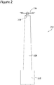
- Figure 2 is a schematic diagram of an exemplary beamed power system 200.
- beamed power system 200 includes a beam source 202, a beam 204, and an unmanned vehicle 206.
- unmanned vehicle 206 is an unmanned aerial vehicle (UAV).
- unmanned vehicle 206 may be a vertical take off and landing (VTOL) UAV.
- VTOL vertical take off and landing
- unmanned vehicle 206 may be any type of unmanned vehicle capable of functioning as described herein, including, but not limited to, an airship, a fixed wing UAV, a ground vehicle, or a water surface vehicle (not shown).
- beam source 202 emits a beam 204.
- Beam 204 is a beam of energy.
- beam source 202 is fixed in position, such that beam source 202 and beam 204 do not track or move with unmanned vehicle 206.
- beam source 202 has a fixed focal length.
- the direction of beam 204 is adjustable and/or beam source 202 may include at least one optical element, such as a lens or concave mirror that enables beam 204 to be expanded or focused at a finite distance.
- beam source 202 converts a source of energy into a relatively narrow electromagnetic beam 204 that is emitted in a fixed direction that is suitable for access by unmanned vehicle 206,
- beam source 202 is coupled to an electrical source of energy.
- any suitable power source can be used to power beam source 202.
- beam source 202 is directed upward, such that beam 204 is emitted substantially vertically.
- beam source 202 is selectively adjustable to enable beam 204 to be emitted in any direction that enables beamed power system 200 to function as described herein.
- beam source 202 is mounted on a stationary ground platform.
- beam source 202 is coupled to a structure or movable vehicle.
- unmanned vehicle 206 includes a power receiver 208 that receives electromagnetic energy emitted from beam source 202.
- power receiver 208 is a photovoltaic receiver
- beam source 202 uses a laser or another monochromatic light source tuned to substantially match a photovoltaic band gap of power receiver 208 on unmanned vehicle 206.
- the light source can be chosen to facilitate maximizing the efficiency of photovoltaic conversion to electricity.
- the light source can be chosen to optimize the beam brightness, thus facilitating maximizing the range at which the beam remains narrow and intense.
- beam source 202 is transmitted using a monochromatic light source.
- a monochromatic light source Those of ordinary skill in the art will appreciate that in other embodiments, other types of beam sources can be used.
- a broad-spectrum beam of visible light such as a halogen lamp or a searchlight.
- Other embodiments may use a microwave beam to maximize end-to-end power conversion efficiency or reduce the observability of beamed power system 200.
- Beam source 202 focuses beam 204 to create a region of intensity at a fixed, finite distance from beam source 202.
- beam source 202 includes multiple individual beam sources that are positioned and oriented to enable their individual beams to intersect to create the region of intensity at the fixed, finite distance from beam source 202.
- beam source 202 creates a region of intensity at a location where the cross section of beam 204 substantially matches the layout of power receiver 208. For example, if a power receiver 208 within unmanned vehicle 206 is a rectangular photovoltaic array, beam source 202 may project a beam 204 that has a substantially rectangular shape near its region of intensity.
- beam source may be configured to a project a beam 204 that has a substantially circular shape near its region of intensity.
- unmanned vehicle 206 is configured to align power receiver 208 with the region of intensity of beam source 202, as described in more detail below.
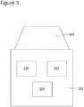
- FIG 3 is a schematic diagram of an exemplary beam source 202 that may be used with the beamed power system 200 shown in Figure 2 .
- beam source 202 includes a locating system 220, a position reference system 222, and a proximity activation system 224.
- locating system 220 aids unmanned vehicle 206 in locating beam 204 when unmanned vehicle 206 is positioned at a distance from beam source 202.
- locating system 220 includes a global positioning system (GPS) that enables the location of beam source 202 to be determined, and a radio that transmits the location of beam source 202 to unmanned vehicle 206.
- GPS global positioning system
- locating system 220 can include any other locating system that enables beamed power system 200 to function as described herein.
- beam source 202 also includes a position reference system 222 that assists unmanned vehicle 206 in centering itself in beam 204 once unmanned vehicle 206 is within a predetermined proximity to beam source 202.
- position reference system 222 transmits a local reference signal such as differential GPS (DGPS).
- DGPS differential GPS
- position reference system 222 can include a set of object features (not shown) that are visible to a camera carried by unmanned vehicle 206.
- Beam source 202 also includes a proximity activation system 224 that activates beam source 202 when unmanned vehicle 206 is within a predefined proximity to beam source 202. Accordingly, proximity activation system 224 is capable of determining whether or not unmanned vehicle 206 is within a predefined distance from beam 204. Using proximity activation system 224, beam source 202 may be selectively energized, depending on a location of unmanned vehicle 206 relative to beam source 202. Alternatively, rather than being deenergized, beam source 202 may switch to a reduced power mode of operation when unmanned vehicle 206 is outside of a predefined proximity.
- proximity activation system 224 includes an acoustic sensor that recognizes a sound emitted by unmanned vehicle 206. Alternatively, proximity activation system 224 may include a visual sensor that recognizes the appearance of unmanned vehicle 206, and/or a radio that receives positional data from unmanned vehicle 206.
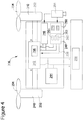
- FIG 4 is a schematic diagram of an exemplary unmanned vehicle 206 that may be used with the beamed power system 200 shown in Figure 2 .
- unmanned vehicle 206 is a vertical take off and landing (VTOL) unmanned aerial vehicle (UAV).
- VTOL vertical take off and landing
- UAV unmanned aerial vehicle
- unmanned vehicle 206 may be a different type of UAV, a ground vehicle, or a water surface vehicle.
- unmanned vehicle 206 is capable of hovering in beam 204.
- unmanned vehicle 206 is a fixed wing UAV that has a high enough thrust-to-weight ratio that enables unmanned vehicle 206 to climb vertically and essentially "hang” from its propeller to remain in a substantially fixed position relative to beam 204.
- unmanned vehicle 206 includes a vehicle propulsion system 240, a control system 242, power receiver 208, an energy storage system 244, one or more payload systems 246, a navigation system 248, and a position control system 250, each of which is described in more detail below. While many embodiments described herein involve interactions between unmanned vehicle 206 and beam 204, those skilled in the art will appreciate that unmanned vehicle 206, as described herein, is also capable of launching and operating when no beam source is available.
- Vehicle propulsion system 240 is used to change or maintain a relative position of unmanned vehicle 206,
- vehicle propulsion system 240 includes at least one motor 252 that is coupled to at least one positioning device 254.
- positioning device 254 is a propeller.
- positioning device 254 may be any device capable of changing a position of unmanned vehicle 206, including, but not limited to, a wheel, a tread, a wing, and/or any device that enables vehicle propulsion system 240 and unmanned vehicle 206 to function as described herein.
- Control system 242 controls the operation of vehicle propulsion system 240. To change or maintain the relative position of unmanned vehicle 206, control system 242 communicates with motor 252 to operate positioning device 254.
- control system includes a power management and distribution (PMAD) system 256 that allocates and routes power to vehicle propulsion system 240, power receiver 208, energy storage system 244, payload systems 246, navigation system 248, and/or position control system 250 for operation of unmanned vehicle 206.
- PMAD system 256 also regulates voltage and/or current output from power receiver 208 to other components of unmanned vehicle 206, and this protects other components from voltage fluctuations or surges in power.
- Control system 242 may also receive commands 258 from navigation system 248 and/or position control system 250, and in response, may instruct vehicle propulsion system 240 to operate accordingly.
- Power receiver 208 receives energy from beam 204 and converts it to a form of energy used to power unmanned vehicle 206.
- power receiver 208 converts energy from beam 204 into electricity.
- beam source 202 emits a laser or other visible light source
- power receiver 208 is a photovoltaic array that produces electricity from the laser or other visible light source.
- beam source 202 emits microwaves
- power receiver 208 is a rectenna.
- Alternative embodiments may include any suitable power receiver 208, including, but not limited to, quantum dot solar cells, or thermal energy receivers that power heat engines inside unmanned vehicle 206.
- a thermal energy receiver may store energy as heat in a thermal energy storage system.
- power receiver 208 can receive a desired form of energy from beam source 202 and convert energy from beam 204 into a desired form of energy capable of powering unmanned vehicle 206 to function as described herein.
- unmanned vehicle 206 includes energy storage system 244.
- Energy storage system 244 provides energy to enable unmanned vehicle 206 to travel outside of beam 204. As such, energy storage system 244 permits unmanned vehicle 206 to travel from a launch or deployment site towards or away from beam 204.
- energy storage system 244 is coupled to power receiver 208 and is capable of being recharged using energy received by power receiver 208 when unmanned vehicle 206 is in beam 204.
- energy storage system 244 may be used to satisfy surge power requirements (i.e. brief demands for higher power than beam 204 generally provides) or to continue operation of unmanned vehicle 206 during interruptions of beam 204.
- unmanned vehicle 206 uses energy stored in energy storage system 244 to travel away from the beam 204, perform a mission, and navigate itself back to beam 204 before the stored energy is depleted.
- power receiver 208 is capable of delivering energy to energy storage system 244 in addition to vehicle propulsion system 240, to control system 242, to payload system 246, to navigation system 248, and to position control system 250.
- energy storage system 244 includes one or more chemical batteries.
- energy storage system can include, but is not limited to including, regenerable fuel cells, a flywheel, and/or a thermal storage device.
- unmanned vehicle 206 includes one or more payload systems 246 that enable unmanned vehicle 206 to perform desired missions.
- Unmanned vehicle 206 is designed to carry payload system 246 to an intended destination and to support operation of payload system 246 by providing power, thermal control, and/or a stable platform.
- Payload system 246 could include cameras, small radars, communication relays, sensors, and other similar components for carrying out desired missions.
- unmanned vehicle 206 includes navigation system 248.
- Navigation system 248 navigates unmanned vehicle through an environment.
- navigation system 248 is configured to navigate unmanned vehicle 206 from a launch site to beam 204.
- Navigation system 248 may also be configured to navigate unmanned vehicle 206 from beam 204 to a target area and then back to beam 204.
- navigation system 248 navigates unmanned vehicle 206 from at least one of the launch site, beam 204, and the target area, to another destination.
- navigation system 248 periodically measures an amount of energy stored in energy storage system 244 and automatically returns unmanned vehicle 206 to beam 204 when the available energy drops below a pre-defined threshold.
- navigation system 248 also includes a navigation computer 260.
- a user can configure navigation computer 260 with GPS coordinates of beam 204, or more specifically, with the region of intensity of beam 204. Accordingly, navigation system 248 may use navigation computer 260 to navigate unmanned vehicle 206 to beam 204 using the GPS signals as a reference.
- navigation system 248 also includes a remote control system 262 that enables a user to remotely direct unmanned vehicle 206 to the beam 204.
- unmanned vehicle 206 also navigates using visual cues detected by a camera 264 and a corresponding image processing system 266. Such visual cues may include flashing lights, object features, or other navigational aids that are adjacent to beam source 202.
- navigation system 248 permits unmanned vehicle 206 to navigate using a radio signal emitted by beam source 202.
- unmanned vehicle 206 includes position control system 250.
- Position control system 250 enables precise movements of unmanned vehicle 206 that may not be possible using navigation system 248.
- navigation system 248, using GPS alone may not be precise enough to keep unmanned vehicle 206 centered in beam 204.
- a relatively small position error may cause power receiver 208 to receive less than a nominal amount of power from beam 204.
- position control system 250 may enable fine positioning of unmanned vehicle 206 relative to beam 204.
- Position control system 250 may also enable fine adjustments for position stability within beam 204. thus enabling unmanned vehicle 206 to hover within beam 204 and facilitating receiving the maximum available power from beam 204,
- position control system 250 measures a power output of power receiver 208, While making small excursions about a mean position of unmanned vehicle 206 with respect to beam 204, position control system 250 measures the power output and the position at which each measurement was made, Position control system 250 correlates this data with a model of the intensity profile of beam 204 to estimate a location of "maximum" beam intensity. Position control system 250 is also configured to position unmanned vehicle 206 near the estimated location to facilitate maximizing power being received by power receiver 208.
- position control system 250 may be configured to associate each power output measurement with a time as well as a position, such that the velocity at which beam source 202 is moving can be calculated.
- This configuration enables unmanned vehicle 206 to remain substantially centered in beam 204, even when beam source 202 is mounted on a moving boat, pickup truck, or other vehicle.
- This enables unmanned vehicle 206 to operate in a variety of situations.
- unmanned vehicle 206 could provide a continuous airborne relay or aerial surveillance for a moving convoy of vehicles.
- position control system 250 includes an inertial measurement unit (IMU) 270.
- IMU 270 enables unmanned vehicle 206 to remain at a given position and attitude despite disruptive events, such as gusts of wind or fluctuations in power.
- position control system 250 also includes one or more sensors 272 that measure a position of unmanned vehicle 206 relative to one or more known features of beam source 202.
- sensor 272 includes a camera 264 that detects naturally occurring or augmented object features, such as painted marks. Camera 264 can also detect optical beacons that flash at known frequencies, such as infrared light-emitting diode blinkers.
- camera 264 performs mission operations as part of payload system 246, and aids in navigation as part of navigation system 248, in addition to measuring the position of unmanned vehicle 206 as part of position control system 250.
- separate cameras could be utilized for each system (not shown).
- FIG 5 is a diagram 300 showing an exemplary use of an exemplary beamed power system, such as beamed power system 200 shown in Figure 2 .
- unmanned vehicle 206 launches from a launch and maintenance area 302.
- navigation system 248 unmanned vehicle 206 navigates to beam 204 at an unmanned vehicle recharge area 304.
- Position control system 250 ensures that unmanned vehicle 206 is substantially centered within beam 204.
- navigation system 248 navigates unmanned vehicle 206 to an area of interest 306.
- Unmanned vehicle 206, using payload system 246, carries out a mission at the area of interest 306.
- unmanned vehicle When the mission is completed or the remaining power of unmanned vehicle 206 drops below a pre-determined threshold, unmanned vehicle returns to unmanned vehicle recharge area 304. Once unmanned vehicle 206 has received sufficient power from beam 204, unmanned vehicle can travel to launch and maintenance area 302, area of interest 306, or another target area, as desired, Those skilled in the art will understand that the beamed power system 200, as described, enables unmanned vehicle 206 to navigate from one of launch and maintenance area 302, unmanned vehicle recharge area 304, and area of interest 306, to another desired area, in various sequences.
- the unmanned vehicle and vehicle system described herein enable the unmanned vehicle to conduct a variety of missions because the unmanned vehicle includes a navigation system for navigating the unmanned vehicle relative to the beam source.
- the beam source described herein is more inexpensive and easier to manufacture than known beam sources because it does not require complicated electrical and mechanical systems for manipulating the direction of the emitted beam.
- the systems described herein facilitate decreasing the cost, weight, vulnerability, complexity, and maintenance requirements of beamed power systems, as well as increasing mission availability and mission duration for unmanned vehicles.
- the systems described herein also eliminate the need for beam steering and control systems, and enable an unmanned vehicle to operate outside of a beam.
- the embodiments described herein enable an unmanned vehicle to move to perform a wide range of useful missions.
- the embodiments described herein also permit a beam source to be mounted and operated from many different platforms and in many different environments.
- a computer or computing device may include one or more processors or processing units, system memory, and some form of computer readable media.
- Exemplary computer readable media include flash memory drives, digital versatile discs (DVDs), compact discs (CDs), floppy disks, and tape cassettes.
- computer readable media comprise computer storage media and communication media.
- Computer storage media store information such as computer readable instructions, data structures, program modules, or other data.
- Communication media typically embody computer readable instructions, data structures, program modules, or other data in a modulated data signal such as a carrier wave or other transport mechanism and include any information delivery media. Combinations of any of the above are also included within the scope of computer readable media.
Description
- The field of the disclosure relates generally to unmanned vehicles and more particularly to powered unmanned aerial vehicles. Unmanned vehicles require energy to operate, and are periodically refueled, repaired, and maintained to continue operating. To increase the availability of unmanned vehicles, it is desirable to minimize the time for ingress/egress, refueling, maintenance, and repair. Beamed power systems may eliminate the need for a vehicle to return to base for refueling or recharging. Moreover, in the case of an unmanned aerial vehicle (UAV), beamed power systems can also reduce landing/takeoff cycles. Thus, beamed power systems can reduce the amount of maintenance and repair for a UAV.
- However, the use of known beamed power systems may be limited. At least some known beamed power systems direct a beam at an unmanned vehicle while it is moving, and as such move the beam to follow the movement of the vehicle. Beam steering generally requires precise, complex moving components for optical systems or mechanically-steered microwave systems, and complex, expensive electronics for phased array microwave systems. Such steering systems add costs, weight, vulnerability, and complexity to a beamed power system.
- At least some other known beamed power systems include a fixed beam source and a vehicle that is coupled to a set of wires or rails that constrain the movement of the vehicle to ensure it remains positioned within the beam. However, because the vehicle is unable to move away from the beam, use of such systems is limited. Other known systems use a fixed beam source to illuminate a vehicle that is not physically tethered with wires or rails. However, in such systems, the vehicle has a propulsive geometry, i.e., predetermined optics and aerodynamics, which ensures the vehicle remains centered in the beam. Again, such systems are limited as the vehicle is unable to move outside of, or operate outside of the beam.
-
EP 0913908 discloses a flying body that has devices suitable for holding the body at predefined altitudes using aerostatic buoyancy, devices for holding the body at predefined longitudinal and transverse positions and an arrangement for supplying the body with power wirelessly from a supply station, for example using laser light. - In one embodiment, an unmanned vehicle is provided. The unmanned vehicle includes a navigation system configured to navigate the unmanned vehicle relative to a beam of energy emitted from a beam source, a power receiver configured to receive energy from the beam, an energy storage system configured to store received energy for use in selectively powering the unmanned vehicle and a position control system configured to enable fine positioning of said unmanned vehicle, wherein said position control system is further configured to measure a power output of said power receiver and a time associated with each power output measurement.
- In another embodiment, a vehicle system is provided. The vehicle system includes a beam source configured to emit a beam of energy, and an unmanned vehicle comprising a navigation system, a power receiver, and an energy storage system, the navigation system configured to position the unmanned vehicle relative to the beam, the power receiver configured to receive energy from the beam, the energy storage system configured to store the received energy for use in powering the unmanned vehicle and further comprising a position control system configured to enable fine positioning of said unmanned vehicle, wherein said position control system is further configured to measure a power output of said power receiver and a time associated with each power output measurement.
-
-
Figure 1 is a schematic diagram of an exemplary known beamed power system. -
Figure 2 is a schematic diagram of an exemplary beamed power system. -
Figure 3 is a schematic diagram of an exemplary beam source, which may be used in the beamed power system shown inFigure 2 . -
Figure 4 is a schematic diagram of an exemplary unmanned vehicle, which may be used in the beamed power system shown inFigure 2 . -
Figure 5 is a diagram showing an exemplary use of an exemplary beamed power system, such as the beamed power system shown inFigure 2 . - The systems described herein overcome at least some of the disadvantages of known beamed power systems. More specifically, the systems described herein provide a beamed power system that has decreased costs, weight, complexity, and maintenance requirements associated with known beamed power systems. In addition, the systems described herein also provide a beam source that may be mounted and operated from a plurality of different platforms and in a plurality of different environments.
-
Figure 1 is a schematic diagram of an exemplary knownbeamed power system 100. In the exemplary embodiment,beamed power system 100 includes abeam source 102, abeam 104, anunmanned vehicle 106, asteering mirror 108, and acontrol system 110.Control system 110 includes aposition sensor 112, acontroller 114, and anoperator control interface 116. During use,control system 110 manipulatessteering mirror 108 to change a relative direction ofbeam 104 emitted frombeam source 102.Position sensor 112 can detect a position ofunmanned vehicle 106 and manipulatesteering mirror 108 to enablebeam 104 to be emitted towardsunmanned vehicle 106.Steering mirror 108 can rotatebeam 104 to trackunmanned vehicle 106 through an angular range, as well as adjust a focal distance ofbeam 104 to maintain proper intensity onunmanned vehicle 106 as a distance of separation betweenunmanned vehicle 106 andbeam source 102 changes, Notably,beamed power system 100 requires sophisticated electronic and mechanical components to operate properly. -
Figure 2 is a schematic diagram of an exemplarybeamed power system 200. In the exemplary embodiment,beamed power system 200 includes abeam source 202, abeam 204, and anunmanned vehicle 206. In an exemplary embodiment,unmanned vehicle 206 is an unmanned aerial vehicle (UAV). In another embodiment,unmanned vehicle 206 may be a vertical take off and landing (VTOL) UAV. Alternatively,unmanned vehicle 206 may be any type of unmanned vehicle capable of functioning as described herein, including, but not limited to, an airship, a fixed wing UAV, a ground vehicle, or a water surface vehicle (not shown). - In the exemplary embodiment,
beam source 202 emits abeam 204.Beam 204 is a beam of energy. In the exemplary embodiment,beam source 202 is fixed in position, such thatbeam source 202 andbeam 204 do not track or move withunmanned vehicle 206. Moreover, in the exemplary embodiment,beam source 202 has a fixed focal length. In alternative embodiments, the direction ofbeam 204 is adjustable and/orbeam source 202 may include at least one optical element, such as a lens or concave mirror that enablesbeam 204 to be expanded or focused at a finite distance. - In the exemplary embodiment,
beam source 202 converts a source of energy into a relatively narrowelectromagnetic beam 204 that is emitted in a fixed direction that is suitable for access byunmanned vehicle 206, In one embodiment,beam source 202 is coupled to an electrical source of energy. In alternate embodiments, any suitable power source can be used topower beam source 202. - In the exemplary embodiment,
beam source 202 is directed upward, such thatbeam 204 is emitted substantially vertically. Alternatively,beam source 202 is selectively adjustable to enablebeam 204 to be emitted in any direction that enables beamedpower system 200 to function as described herein. Moreover, in the exemplary embodiment,beam source 202 is mounted on a stationary ground platform. In alternative embodiments,beam source 202 is coupled to a structure or movable vehicle. - In different aspects, different types of electromagnetic energy are emitted from
beam source 202 to powerunmanned vehicle 206. In each aspect, the type of electromagnetic energy emitted matches the type of electromagnetic energy thatunmanned vehicle 206 is configured to receive and store, as described in more detail below. As such, in the exemplary embodiment,unmanned vehicle 206 includes apower receiver 208 that receives electromagnetic energy emitted frombeam source 202. For example, in one embodiment,power receiver 208 is a photovoltaic receiver, - In one embodiment,
beam source 202 uses a laser or another monochromatic light source tuned to substantially match a photovoltaic band gap ofpower receiver 208 onunmanned vehicle 206. The light source can be chosen to facilitate maximizing the efficiency of photovoltaic conversion to electricity. Alternatively, the light source can be chosen to optimize the beam brightness, thus facilitating maximizing the range at which the beam remains narrow and intense. - In the exemplary embodiment,
beam source 202 is transmitted using a monochromatic light source. Those of ordinary skill in the art will appreciate that in other embodiments, other types of beam sources can be used. For example, one alternative embodiment uses a broad-spectrum beam of visible light (such as a halogen lamp or a searchlight). Other embodiments may use a microwave beam to maximize end-to-end power conversion efficiency or reduce the observability ofbeamed power system 200. -
Beam source 202 focusesbeam 204 to create a region of intensity at a fixed, finite distance frombeam source 202. In one embodiment,beam source 202 includes multiple individual beam sources that are positioned and oriented to enable their individual beams to intersect to create the region of intensity at the fixed, finite distance frombeam source 202. Moreover, in one embodiment,beam source 202 creates a region of intensity at a location where the cross section ofbeam 204 substantially matches the layout ofpower receiver 208. For example, if apower receiver 208 withinunmanned vehicle 206 is a rectangular photovoltaic array,beam source 202 may project abeam 204 that has a substantially rectangular shape near its region of intensity. Alternatively, ifpower receiver 208 has a circular array, beam source may be configured to a project abeam 204 that has a substantially circular shape near its region of intensity. In the exemplary embodiment,unmanned vehicle 206 is configured to alignpower receiver 208 with the region of intensity ofbeam source 202, as described in more detail below. -
Figure 3 is a schematic diagram of anexemplary beam source 202 that may be used with the beamedpower system 200 shown inFigure 2 . In the exemplary embodiment,beam source 202 includes alocating system 220, aposition reference system 222, and aproximity activation system 224. - In the exemplary embodiment, locating
system 220 aidsunmanned vehicle 206 in locatingbeam 204 whenunmanned vehicle 206 is positioned at a distance frombeam source 202. In one embodiment, locatingsystem 220 includes a global positioning system (GPS) that enables the location ofbeam source 202 to be determined, and a radio that transmits the location ofbeam source 202 tounmanned vehicle 206. Alternatively, locatingsystem 220 can include any other locating system that enables beamedpower system 200 to function as described herein. - In the exemplary embodiment,
beam source 202 also includes aposition reference system 222 that assistsunmanned vehicle 206 in centering itself inbeam 204 onceunmanned vehicle 206 is within a predetermined proximity tobeam source 202. In one exemplary embodiment,position reference system 222 transmits a local reference signal such as differential GPS (DGPS). Alternatively,position reference system 222 can include a set of object features (not shown) that are visible to a camera carried byunmanned vehicle 206. -
Beam source 202 also includes aproximity activation system 224 that activatesbeam source 202 whenunmanned vehicle 206 is within a predefined proximity tobeam source 202. Accordingly,proximity activation system 224 is capable of determining whether or notunmanned vehicle 206 is within a predefined distance frombeam 204. Usingproximity activation system 224,beam source 202 may be selectively energized, depending on a location ofunmanned vehicle 206 relative tobeam source 202. Alternatively, rather than being deenergized,beam source 202 may switch to a reduced power mode of operation whenunmanned vehicle 206 is outside of a predefined proximity. In one embodiment,proximity activation system 224 includes an acoustic sensor that recognizes a sound emitted byunmanned vehicle 206. Alternatively,proximity activation system 224 may include a visual sensor that recognizes the appearance ofunmanned vehicle 206, and/or a radio that receives positional data fromunmanned vehicle 206. -
Figure 4 is a schematic diagram of an exemplaryunmanned vehicle 206 that may be used with the beamedpower system 200 shown inFigure 2 . In the exemplary embodiment,unmanned vehicle 206 is a vertical take off and landing (VTOL) unmanned aerial vehicle (UAV). However, in alternative embodiments,unmanned vehicle 206 may be a different type of UAV, a ground vehicle, or a water surface vehicle. For at least some embodiments whereunmanned vehicle 206 is a UAV,unmanned vehicle 206 is capable of hovering inbeam 204. In one embodiment,unmanned vehicle 206 is a fixed wing UAV that has a high enough thrust-to-weight ratio that enablesunmanned vehicle 206 to climb vertically and essentially "hang" from its propeller to remain in a substantially fixed position relative tobeam 204. - In the exemplary embodiment,
unmanned vehicle 206 includes avehicle propulsion system 240, acontrol system 242,power receiver 208, anenergy storage system 244, one ormore payload systems 246, anavigation system 248, and aposition control system 250, each of which is described in more detail below. While many embodiments described herein involve interactions betweenunmanned vehicle 206 andbeam 204, those skilled in the art will appreciate thatunmanned vehicle 206, as described herein, is also capable of launching and operating when no beam source is available. -
Vehicle propulsion system 240 is used to change or maintain a relative position ofunmanned vehicle 206, In the exemplary embodiment,vehicle propulsion system 240 includes at least onemotor 252 that is coupled to at least onepositioning device 254. In the exemplary embodiment,positioning device 254 is a propeller. Alternatively,positioning device 254 may be any device capable of changing a position ofunmanned vehicle 206, including, but not limited to, a wheel, a tread, a wing, and/or any device that enablesvehicle propulsion system 240 andunmanned vehicle 206 to function as described herein. -
Control system 242 controls the operation ofvehicle propulsion system 240. To change or maintain the relative position ofunmanned vehicle 206,control system 242 communicates withmotor 252 to operatepositioning device 254. In the exemplary embodiment, control system includes a power management and distribution (PMAD)system 256 that allocates and routes power tovehicle propulsion system 240,power receiver 208,energy storage system 244,payload systems 246,navigation system 248, and/orposition control system 250 for operation ofunmanned vehicle 206.PMAD system 256 also regulates voltage and/or current output frompower receiver 208 to other components ofunmanned vehicle 206, and this protects other components from voltage fluctuations or surges in power.Control system 242 may also receivecommands 258 fromnavigation system 248 and/orposition control system 250, and in response, may instructvehicle propulsion system 240 to operate accordingly. -
Power receiver 208 receives energy frombeam 204 and converts it to a form of energy used to powerunmanned vehicle 206. For example, in the exemplary embodiment,power receiver 208 converts energy frombeam 204 into electricity. In one aspect,beam source 202 emits a laser or other visible light source, andpower receiver 208 is a photovoltaic array that produces electricity from the laser or other visible light source. In another aspect,beam source 202 emits microwaves, andpower receiver 208 is a rectenna. Alternative embodiments may include anysuitable power receiver 208, including, but not limited to, quantum dot solar cells, or thermal energy receivers that power heat engines insideunmanned vehicle 206. For example, in one embodiment, a thermal energy receiver may store energy as heat in a thermal energy storage system. As such, in different embodiments,power receiver 208 can receive a desired form of energy frombeam source 202 and convert energy frombeam 204 into a desired form of energy capable of poweringunmanned vehicle 206 to function as described herein. - In the exemplary embodiment,
unmanned vehicle 206 includesenergy storage system 244.Energy storage system 244 provides energy to enableunmanned vehicle 206 to travel outside ofbeam 204. As such,energy storage system 244 permitsunmanned vehicle 206 to travel from a launch or deployment site towards or away frombeam 204. In an exemplary embodiment,energy storage system 244 is coupled topower receiver 208 and is capable of being recharged using energy received bypower receiver 208 whenunmanned vehicle 206 is inbeam 204. Moreover, whileunmanned vehicle 206 is positioned withinbeam 204,energy storage system 244 may be used to satisfy surge power requirements (i.e. brief demands for higher power thanbeam 204 generally provides) or to continue operation ofunmanned vehicle 206 during interruptions ofbeam 204. In other embodiments,unmanned vehicle 206 uses energy stored inenergy storage system 244 to travel away from thebeam 204, perform a mission, and navigate itself back tobeam 204 before the stored energy is depleted. - In the exemplary embodiment,
power receiver 208 is capable of delivering energy toenergy storage system 244 in addition tovehicle propulsion system 240, to controlsystem 242, topayload system 246, tonavigation system 248, and to positioncontrol system 250. In one embodiment,energy storage system 244 includes one or more chemical batteries. In alternative embodiments, energy storage system can include, but is not limited to including, regenerable fuel cells, a flywheel, and/or a thermal storage device. - In the exemplary embodiment,
unmanned vehicle 206 includes one ormore payload systems 246 that enableunmanned vehicle 206 to perform desired missions.Unmanned vehicle 206 is designed to carrypayload system 246 to an intended destination and to support operation ofpayload system 246 by providing power, thermal control, and/or a stable platform.Payload system 246 could include cameras, small radars, communication relays, sensors, and other similar components for carrying out desired missions. - In the exemplary embodiment,
unmanned vehicle 206 includesnavigation system 248.Navigation system 248 navigates unmanned vehicle through an environment. In one embodiment,navigation system 248 is configured to navigateunmanned vehicle 206 from a launch site tobeam 204.Navigation system 248 may also be configured to navigateunmanned vehicle 206 frombeam 204 to a target area and then back tobeam 204. Thus, in the exemplary embodiment,navigation system 248 navigatesunmanned vehicle 206 from at least one of the launch site,beam 204, and the target area, to another destination. - In the exemplary embodiment,
navigation system 248 periodically measures an amount of energy stored inenergy storage system 244 and automatically returnsunmanned vehicle 206 tobeam 204 when the available energy drops below a pre-defined threshold. In the exemplary embodiment,navigation system 248 also includes anavigation computer 260. A user can configurenavigation computer 260 with GPS coordinates ofbeam 204, or more specifically, with the region of intensity ofbeam 204. Accordingly,navigation system 248 may usenavigation computer 260 to navigateunmanned vehicle 206 tobeam 204 using the GPS signals as a reference. - In the exemplary embodiment,
navigation system 248 also includes aremote control system 262 that enables a user to remotely directunmanned vehicle 206 to thebeam 204. In the exemplary embodiment,unmanned vehicle 206 also navigates using visual cues detected by acamera 264 and a correspondingimage processing system 266. Such visual cues may include flashing lights, object features, or other navigational aids that are adjacent tobeam source 202. In another embodiment,navigation system 248 permitsunmanned vehicle 206 to navigate using a radio signal emitted bybeam source 202. - In the exemplary embodiment,
unmanned vehicle 206 includesposition control system 250.Position control system 250 enables precise movements ofunmanned vehicle 206 that may not be possible usingnavigation system 248. For example, in one aspect, whenbeam 204 is relatively narrow,navigation system 248, using GPS alone, may not be precise enough to keepunmanned vehicle 206 centered inbeam 204. More specifically, whenbeam 204 is relatively narrow and/orpower receiver 208 is relatively small, a relatively small position error may causepower receiver 208 to receive less than a nominal amount of power frombeam 204. In contrast to using GPS,position control system 250 may enable fine positioning ofunmanned vehicle 206 relative tobeam 204.Position control system 250 may also enable fine adjustments for position stability withinbeam 204. thus enablingunmanned vehicle 206 to hover withinbeam 204 and facilitating receiving the maximum available power frombeam 204, - In the exemplary embodiment,
position control system 250 measures a power output ofpower receiver 208, While making small excursions about a mean position ofunmanned vehicle 206 with respect tobeam 204,position control system 250 measures the power output and the position at which each measurement was made,Position control system 250 correlates this data with a model of the intensity profile ofbeam 204 to estimate a location of "maximum" beam intensity.Position control system 250 is also configured to positionunmanned vehicle 206 near the estimated location to facilitate maximizing power being received bypower receiver 208. - Further, in embodiments where
beam source 202 is mounted to a moving vehicle,position control system 250 may be configured to associate each power output measurement with a time as well as a position, such that the velocity at whichbeam source 202 is moving can be calculated. This configuration enablesunmanned vehicle 206 to remain substantially centered inbeam 204, even whenbeam source 202 is mounted on a moving boat, pickup truck, or other vehicle. This enablesunmanned vehicle 206 to operate in a variety of situations. For example,unmanned vehicle 206 could provide a continuous airborne relay or aerial surveillance for a moving convoy of vehicles. - In the exemplary embodiment,
position control system 250 includes an inertial measurement unit (IMU) 270.IMU 270 enablesunmanned vehicle 206 to remain at a given position and attitude despite disruptive events, such as gusts of wind or fluctuations in power. In the exemplary embodiment,position control system 250 also includes one ormore sensors 272 that measure a position ofunmanned vehicle 206 relative to one or more known features ofbeam source 202. In one embodiment,sensor 272 includes acamera 264 that detects naturally occurring or augmented object features, such as painted marks.Camera 264 can also detect optical beacons that flash at known frequencies, such as infrared light-emitting diode blinkers. In the exemplary embodiment,camera 264 performs mission operations as part ofpayload system 246, and aids in navigation as part ofnavigation system 248, in addition to measuring the position ofunmanned vehicle 206 as part ofposition control system 250. Alternatively, separate cameras could be utilized for each system (not shown). -
Figure 5 is a diagram 300 showing an exemplary use of an exemplary beamed power system, such as beamedpower system 200 shown inFigure 2 . In the exemplary embodiment,unmanned vehicle 206 launches from a launch andmaintenance area 302. Usingnavigation system 248,unmanned vehicle 206 navigates tobeam 204 at an unmannedvehicle recharge area 304.Position control system 250 ensures thatunmanned vehicle 206 is substantially centered withinbeam 204. Whenunmanned vehicle 206 is sufficiently charged,navigation system 248 navigatesunmanned vehicle 206 to an area ofinterest 306.Unmanned vehicle 206, usingpayload system 246, carries out a mission at the area ofinterest 306. When the mission is completed or the remaining power ofunmanned vehicle 206 drops below a pre-determined threshold, unmanned vehicle returns to unmannedvehicle recharge area 304. Onceunmanned vehicle 206 has received sufficient power frombeam 204, unmanned vehicle can travel to launch andmaintenance area 302, area ofinterest 306, or another target area, as desired, Those skilled in the art will understand that the beamedpower system 200, as described, enablesunmanned vehicle 206 to navigate from one of launch andmaintenance area 302, unmannedvehicle recharge area 304, and area ofinterest 306, to another desired area, in various sequences. - As compared to known unmanned vehicles and vehicle systems, the unmanned vehicle and vehicle system described herein enable the unmanned vehicle to conduct a variety of missions because the unmanned vehicle includes a navigation system for navigating the unmanned vehicle relative to the beam source. Moreover, the beam source described herein is more inexpensive and easier to manufacture than known beam sources because it does not require complicated electrical and mechanical systems for manipulating the direction of the emitted beam.
- The systems described herein facilitate decreasing the cost, weight, vulnerability, complexity, and maintenance requirements of beamed power systems, as well as increasing mission availability and mission duration for unmanned vehicles. The systems described herein also eliminate the need for beam steering and control systems, and enable an unmanned vehicle to operate outside of a beam. Moreover, the embodiments described herein enable an unmanned vehicle to move to perform a wide range of useful missions. The embodiments described herein also permit a beam source to be mounted and operated from many different platforms and in many different environments.
- The systems described herein may be implemented or performed using one or more computers or computing devices. A computer or computing device may include one or more processors or processing units, system memory, and some form of computer readable media. Exemplary computer readable media include flash memory drives, digital versatile discs (DVDs), compact discs (CDs), floppy disks, and tape cassettes. By way of example and not limitation, computer readable media comprise computer storage media and communication media. Computer storage media store information such as computer readable instructions, data structures, program modules, or other data. Communication media typically embody computer readable instructions, data structures, program modules, or other data in a modulated data signal such as a carrier wave or other transport mechanism and include any information delivery media. Combinations of any of the above are also included within the scope of computer readable media.
- This written description uses examples to disclose various embodiments, which include the best mode, to enable any person skilled in the art to practice those embodiments, including making and using any devices or systems and performing any incorporated methods. The patentable scope is defined by the claims.
Claims (13)
- An unmanned vehicle (206), comprising:a navigation system (248) configured to navigate said unmanned vehicle (206) relative to a beam of energy (204) emitted from a beam source (202);a power receiver (208) configured to receive energy from the beam (204);an energy storage system (244) configured to store received energy for use in selectively powering said unmanned vehicle (206); anda position control system (250) configured to enable fine positioning of said unmanned vehicle (206), wherein said position control system (250) is further configured to measure a power output of said power receiver (208) and a time associated with each power output measurement to calculate the velocity at which the beam source is moving,wherein the unmanned vehicle (206) is configured such that a proximity activation system (224) of the beam source (202) activates the beam source (202) when the unmanned vehicle (206) is within a predefined proximity to the beam source (202), andwherein the beam source (202) is configured to focus the beam (204) to create a region of intensity at a fixed, finite distance from the beam source (202), wherein the beam source (202) includes multiple individual beam sources that are positioned and oriented to enable their individual beams to intersect to create the region of intensity at the fixed, finite distance from the beam source (202), and wherein the unmanned vehicle (206) is configured to align the power receiver (208) with the region of intensity of the beam source (202).
- The unmanned vehicle (206) in accordance with Claim 1, wherein said unmanned vehicle (206) is an unmanned aerial vehicle "UAV".
- The unmanned vehicle (206) in accordance with any preceding claim further comprising a vehicle propulsion system (240) configured to propel said unmanned vehicle (206), said vehicle propulsion system (240) comprising at least one motor (252) and at least one positioning device (254).
- The unmanned vehicle (206) in accordance with Claims 1 - 2 further comprising:a control system (242); anda vehicle propulsion system (240), said control system (242) configured to control a position of said unmanned vehicle (206) using said vehicle propulsion system (240).
- The unmanned vehicle (206) in accordance with Claim 4, wherein said control system (242) comprises a power management and distribution system (256) for use in selectively allocating power to said unmanned vehicle (206).
- The unmanned vehicle (206) in accordance with any preceding claim, wherein said power receiver (208) comprises at least one of a photovoltaic array and a rectenna.
- The unmanned vehicle (206) in accordance with any preceding claim, wherein said navigation system (248) is further configured to:measure an amount of energy stored in said energy storage system (244); andguide said unmanned vehicle (206) to the beam of energy when the energy stored is below a pre-determined threshold, wherein said navigation system (248) is further configured to utilize at least one of global positioning system "GPS" coordinates, visual cues, and radio signals, to navigate said unmanned vehicle (206).
- The unmanned vehicle (206) in accordance with Claim 1, wherein said position control system (250) comprises an inertial measurement unit (270) and at least one sensor (272) configured to measure a relative position of said unmanned vehicle (206), wherein said at least one sensor (272) comprises a camera (264) configured to detect at least one of object features and optical beacons.
- A vehicle system, comprising:a beam source (202) configured to emit a beam of energy (204); andan unmanned vehicle (206) comprising a navigation system (248), a power receiver (208), and an energy storage system (244), said navigation system (248) configured to position said unmanned vehicle (206) relative to the beam (202), said power receiver (208) configured to receive energy from the beam (202), said energy storage system (244) configured to store received energy for use in powering said unmanned vehicle (206); and further comprising a position control system (250) configured to enable fine positioning of said unmanned vehicle (206), wherein said position control system (250) is further configured to measure a power output of said power receiver (208) and a time associated with each power output measurement to calculate the velocity at which the beam source is moving,wherein the unmanned vehicle (206) is configured such that a proximity activation system (224) of the beam source (202) activates the beam source (202) when the unmanned vehicle (206) is within a predefined proximity to the beam source (202),wherein the beam source (202) is configured to focus the beam (204) to create a region of intensity at a fixed, finite distance from the beam source (202), wherein the beam source (202) includes multiple individual beam sources that are positioned and oriented to enable their individual beams to intersect to create the region of intensity at the fixed, finite distance from the beam source (202), and wherein the unmanned vehicle (206) is configured to align the power receiver (208) with the region of intensity of the beam source (202).
- The system in accordance with Claim 9, wherein said beam source (202) comprises a locating system (220) configured to aid said unmanned vehicle (206) in locating the beam (202), wherein said locating system comprises a global positioning system "GPS".
- The system in accordance with Claims 9 - 10, wherein said beam source (202) comprises a position reference system (222) configured to substantially center said unmanned vehicle (206) relative to said beam (202).
- The system in accordance with Claim 11, wherein said position reference system (222) comprises at least one of a local reference signal and a set of object features visible to a camera coupled to said unmanned vehicle (206).
- The system in accordance with Claims 9 - 12, wherein said proximity activation system (224) comprises at least one of an acoustic sensor configured to recognize a sound emitted by said unmanned vehicle (206), a visual sensor configured to recognize an appearance of said unmanned vehicle (206), and a radio configured to receive positional data from said unmanned vehicle (206).
Applications Claiming Priority (2)
| Application Number | Priority Date | Filing Date | Title |
|---|---|---|---|
| US12/964,500 US8788119B2 (en) | 2010-12-09 | 2010-12-09 | Unmanned vehicle and system |
| PCT/US2011/053133 WO2012078232A1 (en) | 2010-12-09 | 2011-09-23 | Unmanned vehicle and system |
Publications (2)
| Publication Number | Publication Date |
|---|---|
| EP2649702A1 EP2649702A1 (en) | 2013-10-16 |
| EP2649702B1 true EP2649702B1 (en) | 2019-05-15 |
Family
ID=44801161
Family Applications (1)
| Application Number | Title | Priority Date | Filing Date |
|---|---|---|---|
| EP11770241.5A Active EP2649702B1 (en) | 2010-12-09 | 2011-09-23 | Unmanned vehicle and system |
Country Status (4)
| Country | Link |
|---|---|
| US (1) | US8788119B2 (en) |
| EP (1) | EP2649702B1 (en) |
| JP (1) | JP5988391B2 (en) |
| WO (1) | WO2012078232A1 (en) |
Families Citing this family (73)
| Publication number | Priority date | Publication date | Assignee | Title |
|---|---|---|---|---|
| WO2013105926A1 (en) * | 2011-03-22 | 2013-07-18 | Aerovironment Inc. | Invertible aircraft |
| WO2013052178A2 (en) * | 2011-06-09 | 2013-04-11 | Lasermotive, Inc. | An aerial platform system, and related methods |
| US8909391B1 (en) * | 2012-12-28 | 2014-12-09 | Google Inc. | Responsive navigation of an unmanned aerial vehicle to a remedial facility |
| US8991447B1 (en) | 2013-06-27 | 2015-03-31 | The United States Of America As Represented By The Secretary Of The Navy | Ship or air deployable automated buoy refueling station for multiple manned or unmanned surface vessels |
| CN104377747A (en) * | 2013-08-12 | 2015-02-25 | 贵州贵航飞机设计研究所 | Method for improving duration performance of unmanned aerial vehicle through wireless charging technology |
| US9936114B2 (en) | 2013-10-25 | 2018-04-03 | Elwha Llc | Mobile device for requesting the capture of an image |
| FR3012923B1 (en) | 2013-11-04 | 2017-09-01 | European Aeronautic Defence & Space Co Eads France | DEVICE FOR REMOTELY TRANSFERRING ENERGY BY ACOUSTIC WAVES TO A MOVING OBJECT |
| US9859972B2 (en) | 2014-02-17 | 2018-01-02 | Ubiqomm Llc | Broadband access to mobile platforms using drone/UAV background |
| KR101633675B1 (en) * | 2014-02-27 | 2016-06-28 | 연세대학교 산학협력단 | System and method for wireless power supply of remotely piloted vehicle |
| US20160052644A1 (en) * | 2014-08-20 | 2016-02-25 | Elwha Llc | Unmanned aerial vehicle having an onboard cleaning device |
| US9993852B2 (en) | 2014-08-20 | 2018-06-12 | Elwha Llc | Surface cleaning unmanned aerial vehicle |
| US9571180B2 (en) | 2014-10-16 | 2017-02-14 | Ubiqomm Llc | Unmanned aerial vehicle (UAV) beam forming and pointing toward ground coverage area cells for broadband access |
| WO2016068767A1 (en) * | 2014-10-30 | 2016-05-06 | Acc Innovation Ab | Multi-rotor aerial vehicle |
| US9712228B2 (en) | 2014-11-06 | 2017-07-18 | Ubiqomm Llc | Beam forming and pointing in a network of unmanned aerial vehicles (UAVs) for broadband access |
| US20160214713A1 (en) * | 2014-12-19 | 2016-07-28 | Brandon Cragg | Unmanned aerial vehicle with lights, audio and video |
| IL237130A0 (en) * | 2015-02-05 | 2015-11-30 | Ran Krauss | Landing and charging system for drones |
| US9435635B1 (en) * | 2015-02-27 | 2016-09-06 | Ge Aviation Systems Llc | System and methods of detecting an intruding object in a relative navigation system |
| US9590720B2 (en) | 2015-05-13 | 2017-03-07 | Ubiqomm Llc | Ground terminal and gateway beam pointing toward an unmanned aerial vehicle (UAV) for network access |
| US9660718B2 (en) | 2015-05-13 | 2017-05-23 | Ubiqomm, LLC | Ground terminal and UAV beam pointing in an unmanned aerial vehicle (UAV) for network access |
| CN105035340A (en) * | 2015-06-18 | 2015-11-11 | 顺丰科技有限公司 | Multifunctional flying platform based on unmanned aerial vehicle |
| US10633102B2 (en) | 2015-06-29 | 2020-04-28 | Panasonic Intellectual Property Management Co., Ltd. | Screen device and image projection system |
| KR102083934B1 (en) * | 2015-07-02 | 2020-03-03 | 한화디펜스 주식회사 | Method and apparaus for automatic landing of aircraft using vision-based information |
| US10374466B2 (en) * | 2015-08-14 | 2019-08-06 | Lasermotive, Inc. | Energy efficient vehicle with integrated power beaming |
| US10264650B2 (en) * | 2015-08-31 | 2019-04-16 | The Boeing Company | System and method for contactless energy transfer to a moving platform |
| JP6730704B2 (en) * | 2015-09-14 | 2020-07-29 | 学校法人立命館 | Rotorcraft and power supply system |
| US10933997B2 (en) * | 2015-10-02 | 2021-03-02 | Insitu, Inc. | Aerial launch and/or recovery for unmanned aircraft, and associated systems and methods |
| US9776717B2 (en) | 2015-10-02 | 2017-10-03 | The Boeing Company | Aerial agricultural management system |
| CN105226836B (en) * | 2015-10-20 | 2017-12-29 | 杨珊珊 | A kind of unmanned plane for being capable of automatic charging, unmanned plane charging system and charging method |
| KR101854013B1 (en) * | 2015-10-23 | 2018-05-02 | 현대로템 주식회사 | Wireless charging system and method |
| EP4001111A3 (en) * | 2015-11-10 | 2022-08-17 | Matternet, Inc. | Methods and system for transportation using unmanned aerial vehicles |
| KR102083935B1 (en) * | 2015-11-10 | 2020-03-03 | 한화디펜스 주식회사 | Unmanned Air Vehicle |
| US10155586B2 (en) * | 2015-12-29 | 2018-12-18 | Facebook, Inc. | Remotely supplied power for unmanned aerial vehicle |
| JP6745181B2 (en) * | 2016-02-16 | 2020-08-26 | パナソニック インテレクチュアル プロパティ コーポレーション オブ アメリカPanasonic Intellectual Property Corporation of America | Light emission control device, unmanned air vehicle, and light emission control method |
| US9858821B2 (en) * | 2016-02-26 | 2018-01-02 | Ford Global Technologies, Llc | Autonomous vehicle passenger locator |
| JP2017163636A (en) * | 2016-03-07 | 2017-09-14 | 株式会社豊田中央研究所 | Energy transmitter, energy receiver, energy transmitter receiver, and wireless power supply system with them |
| US10053218B2 (en) | 2016-03-31 | 2018-08-21 | General Electric Company | System and method for positioning an unmanned aerial vehicle |
| CN105700544A (en) * | 2016-04-08 | 2016-06-22 | 暨南大学 | UAV tour inspection system and implementation method for electrical equipment of photovoltaic power station |
| US10005555B2 (en) * | 2016-05-02 | 2018-06-26 | Qualcomm Incorporated | Imaging using multiple unmanned aerial vehicles |
| WO2017193083A1 (en) * | 2016-05-06 | 2017-11-09 | Ubiqomm Llc | Unmanned aerial vehicle (uav) beam pointing and data rate optimization for high throughput broadband access |
| US10321461B2 (en) | 2016-05-06 | 2019-06-11 | Bridgewest Finance Llc | Unmanned aerial vehicle (UAV) beam pointing and data rate optimization for high throughput broadband access |
| WO2017203590A1 (en) * | 2016-05-24 | 2017-11-30 | 中国電力株式会社 | Flight system for flight vehicle, and flight method for flight vehicle |
| CN109804528B (en) * | 2016-07-11 | 2023-04-18 | 韩国科学技术院 | Wireless charging device and method capable of detecting optimal charging position stronger than deviation |
| CN108233445B (en) * | 2016-12-15 | 2021-01-19 | 比亚迪股份有限公司 | Charging control method and device for vehicle |
| US10608830B2 (en) | 2017-02-06 | 2020-03-31 | Mh Gopower Company Limited | Power over fiber enabled sensor system |
| CN106813666B (en) * | 2017-02-13 | 2019-10-18 | 中国人民解放军国防科学技术大学 | The double-deck path construction method and system of vehicle loading unmanned plane |
| US11148802B1 (en) | 2017-06-22 | 2021-10-19 | Arrowhead Center, Inc. | Robust cooperative localization and navigation of tethered heterogeneous autonomous unmanned vehicles in resource-constrained environments |
| US20190004544A1 (en) * | 2017-06-29 | 2019-01-03 | Ge Aviation Systems, Llc | Method for flying at least two aircraft |
| US11142433B2 (en) | 2018-02-08 | 2021-10-12 | Vita Inclinata Technologies, Inc. | Bidirectional thrust apparatus, system, and method |
| US11142316B2 (en) | 2018-02-08 | 2021-10-12 | Vita Inclinata Technologies, Inc. | Control of drone-load system method, system, and apparatus |
| US10940061B2 (en) | 2018-02-08 | 2021-03-09 | Vita Inclinata Technologies, Inc. | Modular suspended load control apparatuses, systems, and methods |
| FI12547U1 (en) * | 2018-02-08 | 2020-01-15 | Vita Inclinata Tech Inc | Load stability system apparatus |
| US11209836B1 (en) | 2018-02-08 | 2021-12-28 | Vita Inclinata Technologies, Inc. | Long line loiter apparatus, system, and method |
| US11945697B2 (en) | 2018-02-08 | 2024-04-02 | Vita Inclinata Ip Holdings Llc | Multiple remote control for suspended load control equipment apparatus, system, and method |
| RU2710035C1 (en) * | 2018-02-12 | 2019-12-24 | ФЕДЕРАЛЬНОЕ ГОСУДАРСТВЕННОЕ БЮДЖЕТНОЕ ОБРАЗОВАТЕЛЬНОЕ УЧРЕЖДЕНИЕ ВЫСШЕГО ОБРАЗОВАНИЯ "Брянский государственный технический университет" | Method for wireless transmission of energy from one unmanned aerial vehicle to another |
| US11476376B2 (en) * | 2018-03-28 | 2022-10-18 | National Technology & Engineering Solutions Of Sandia, Llc | Photovoltaic array for a power-by-light system |
| CN109002048B (en) * | 2018-06-12 | 2020-06-09 | 浙江大学 | Multi-rotor unmanned aerial vehicle large-scale centralized photovoltaic power station image data acquisition method |
| US11040780B2 (en) * | 2018-08-07 | 2021-06-22 | Raytheon Technologies Corporation | Inertial energy storage device |
| CN109245221B (en) * | 2018-10-12 | 2021-06-04 | Oppo(重庆)智能科技有限公司 | Wireless charging method and system for mobile terminal and wireless charger |
| JP6738917B1 (en) * | 2019-02-01 | 2020-08-12 | 三菱ロジスネクスト株式会社 | Power supply system for unmanned air vehicles |
| JP6663054B1 (en) * | 2019-02-05 | 2020-03-11 | 三菱ロジスネクスト株式会社 | Power supply system and vehicle for unmanned aerial vehicles |
| JP6674570B1 (en) * | 2019-02-22 | 2020-04-01 | 三菱ロジスネクスト株式会社 | Power supply system for unmanned aerial vehicles |
| JP6680450B1 (en) * | 2019-02-22 | 2020-04-15 | 三菱ロジスネクスト株式会社 | Unmanned aerial vehicle power supply system and unmanned power supply vehicle |
| WO2020176665A1 (en) | 2019-02-26 | 2020-09-03 | Vita Inclinata Technologies, Inc. | Cable deployment apparatus, system, and methods for suspended load control equipment |
| JP6821733B2 (en) * | 2019-03-26 | 2021-01-27 | ソフトバンク株式会社 | Communication equipment, communication methods, and programs |
| JP7270440B2 (en) * | 2019-03-28 | 2023-05-10 | 三菱電機株式会社 | WIRELESS POWER TRANSMISSION SYSTEM AND WIRELESS POWER TRANSMISSION METHOD |
| US11618566B1 (en) | 2019-04-12 | 2023-04-04 | Vita Inclinata Technologies, Inc. | State information and telemetry for suspended load control equipment apparatus, system, and method |
| US11834305B1 (en) | 2019-04-12 | 2023-12-05 | Vita Inclinata Ip Holdings Llc | Apparatus, system, and method to control torque or lateral thrust applied to a load suspended on a suspension cable |
| US11217356B2 (en) | 2019-06-28 | 2022-01-04 | The Boeing Company | Radioisotope power source |
| EP3999463A4 (en) | 2019-07-21 | 2023-08-30 | Vita Inclinata IP Holdings LLC | Hoist and deployable equipment apparatus, system, and method |
| US11876388B2 (en) | 2019-11-07 | 2024-01-16 | The Boeing Company | Beamed power system and method |
| US11165506B2 (en) | 2020-01-17 | 2021-11-02 | The Boeing Company | Drone network and method of operating |
| WO2022039181A1 (en) * | 2020-08-18 | 2022-02-24 | 三菱電機株式会社 | Flying mobile body and wireless power transmission system |
| WO2023211499A1 (en) | 2022-04-29 | 2023-11-02 | Vita Inclinata Ip Holdings Llc | Machine learning real property object detection and analysis apparatus, system, and method |
Family Cites Families (16)
| Publication number | Priority date | Publication date | Assignee | Title |
|---|---|---|---|---|
| US5503350A (en) | 1993-10-28 | 1996-04-02 | Skysat Communications Network Corporation | Microwave-powered aircraft |
| US6792259B1 (en) | 1997-05-09 | 2004-09-14 | Ronald J. Parise | Remote power communication system and method thereof |
| DE19748262A1 (en) | 1997-10-31 | 1999-05-12 | Fraunhofer Ges Forschung | Missiles for essentially stationary stays at heights up to the stratosphere |
| JP3526402B2 (en) * | 1998-05-29 | 2004-05-17 | 株式会社東芝 | Landing guidance system |
| US6955324B2 (en) | 2003-10-22 | 2005-10-18 | The Boeing Company | Laser-tethered vehicle |
| JP4632889B2 (en) * | 2005-07-19 | 2011-02-16 | 三菱電機株式会社 | Power supply system for flying object and power transmission device and flying object used for flying object |
| US8735712B2 (en) | 2006-07-21 | 2014-05-27 | The Boeing Company | Photovoltaic receiver for beamed power |
| US7813888B2 (en) | 2006-07-24 | 2010-10-12 | The Boeing Company | Autonomous vehicle rapid development testbed systems and methods |
| IL177948A (en) * | 2006-09-07 | 2011-02-28 | Elbit Systems Ltd | Method and system for extending operational electronic range of a vehicle |
| US7711441B2 (en) | 2007-05-03 | 2010-05-04 | The Boeing Company | Aiming feedback control for multiple energy beams |
| US8060270B2 (en) | 2008-02-29 | 2011-11-15 | The Boeing Company | System and method for inspection of structures and objects by swarm of remote unmanned vehicles |
| US20110226174A1 (en) * | 2008-06-16 | 2011-09-22 | Aurora Flight Sciences Corporation | Combined submersible vessel and unmanned aerial vehicle |
| JP5231149B2 (en) * | 2008-09-25 | 2013-07-10 | 株式会社ジャムコ | Power frequency converter |
| JP2010075568A (en) * | 2008-09-26 | 2010-04-08 | Nikko:Kk | Helicopter toy |
| US8190382B2 (en) | 2008-12-03 | 2012-05-29 | The Boeing Company | Tool to analyze performance of power-beam photovoltaic receiver |
| US8816632B2 (en) * | 2010-04-28 | 2014-08-26 | Lockheed Martin Corporation | Radio frequency power transmission system |
-
2010
- 2010-12-09 US US12/964,500 patent/US8788119B2/en active Active
-
2011
- 2011-09-23 EP EP11770241.5A patent/EP2649702B1/en active Active
- 2011-09-23 JP JP2013543164A patent/JP5988391B2/en active Active
- 2011-09-23 WO PCT/US2011/053133 patent/WO2012078232A1/en active Application Filing
Non-Patent Citations (1)
| Title |
|---|
| None * |
Also Published As
| Publication number | Publication date |
|---|---|
| WO2012078232A1 (en) | 2012-06-14 |
| EP2649702A1 (en) | 2013-10-16 |
| JP2014500827A (en) | 2014-01-16 |
| US20120150364A1 (en) | 2012-06-14 |
| US8788119B2 (en) | 2014-07-22 |
| JP5988391B2 (en) | 2016-09-07 |
Similar Documents
| Publication | Publication Date | Title |
|---|---|---|
| EP2649702B1 (en) | Unmanned vehicle and system | |
| US11332033B2 (en) | Systems and methods for UAV battery exchange | |
| AU2018355071B2 (en) | UAV group charging based on demand for UAV service | |
| US11807361B2 (en) | Vision based calibration system for unmanned aerial vehicles | |
| US10611252B2 (en) | Systems and methods for UAV battery power backup | |
| US9550582B2 (en) | Multi-zone battery exchange system | |
| EP3379361B1 (en) | System with a vehicle and a coupled drone acting as signal output of the vehicle | |
| US10328805B1 (en) | Battery management system for electric vehicles | |
| JP6538214B2 (en) | Method of supplying energy to UAV, and UAV | |
| CN107434034A (en) | With vertical takeoff and landing(VTOL)The unmanned vehicle of function(UAV) | |
| CN111527460A (en) | Methods and systems using deployed Unmanned Aerial Vehicles (UAVs) dedicated to operating infrastructure |
Legal Events
| Date | Code | Title | Description |
|---|---|---|---|
| PUAI | Public reference made under article 153(3) epc to a published international application that has entered the european phase |
Free format text: ORIGINAL CODE: 0009012 |
|
| 17P | Request for examination filed |
Effective date: 20130704 |
|
| AK | Designated contracting states |
Kind code of ref document: A1 Designated state(s): AL AT BE BG CH CY CZ DE DK EE ES FI FR GB GR HR HU IE IS IT LI LT LU LV MC MK MT NL NO PL PT RO RS SE SI SK SM TR |
|
| DAX | Request for extension of the european patent (deleted) | ||
| 17Q | First examination report despatched |
Effective date: 20150626 |
|
| REG | Reference to a national code |
Ref country code: DE Ref legal event code: R079 Ref document number: 602011058998 Country of ref document: DE Free format text: PREVIOUS MAIN CLASS: H02J0017000000 Ipc: G05D0001100000 |
|
| GRAP | Despatch of communication of intention to grant a patent |
Free format text: ORIGINAL CODE: EPIDOSNIGR1 |
|
| STAA | Information on the status of an ep patent application or granted ep patent |
Free format text: STATUS: GRANT OF PATENT IS INTENDED |
|
| RIC1 | Information provided on ipc code assigned before grant |
Ipc: G05D 1/10 20060101AFI20180918BHEP |
|
| INTG | Intention to grant announced |
Effective date: 20181010 |
|
| RIN1 | Information on inventor provided before grant (corrected) |
Inventor name: ROSS, TAMAIRA E. Inventor name: TILLOTSON, BRIAN J. Inventor name: VIAN, JOHN L. |
|
| GRAS | Grant fee paid |
Free format text: ORIGINAL CODE: EPIDOSNIGR3 |
|
| GRAJ | Information related to disapproval of communication of intention to grant by the applicant or resumption of examination proceedings by the epo deleted |
Free format text: ORIGINAL CODE: EPIDOSDIGR1 |
|
| GRAL | Information related to payment of fee for publishing/printing deleted |
Free format text: ORIGINAL CODE: EPIDOSDIGR3 |
|
| STAA | Information on the status of an ep patent application or granted ep patent |
Free format text: STATUS: EXAMINATION IS IN PROGRESS |
|
| GRAR | Information related to intention to grant a patent recorded |
Free format text: ORIGINAL CODE: EPIDOSNIGR71 |
|
| STAA | Information on the status of an ep patent application or granted ep patent |
Free format text: STATUS: GRANT OF PATENT IS INTENDED |
|
| INTC | Intention to grant announced (deleted) | ||
| GRAA | (expected) grant |
Free format text: ORIGINAL CODE: 0009210 |
|
| STAA | Information on the status of an ep patent application or granted ep patent |
Free format text: STATUS: THE PATENT HAS BEEN GRANTED |
|
| INTG | Intention to grant announced |
Effective date: 20190312 |
|
| AK | Designated contracting states |
Kind code of ref document: B1 Designated state(s): AL AT BE BG CH CY CZ DE DK EE ES FI FR GB GR HR HU IE IS IT LI LT LU LV MC MK MT NL NO PL PT RO RS SE SI SK SM TR |
|
| REG | Reference to a national code |
Ref country code: CH Ref legal event code: EP Ref country code: GB Ref legal event code: FG4D |
|
| REG | Reference to a national code |
Ref country code: DE Ref legal event code: R096 Ref document number: 602011058998 Country of ref document: DE |
|
| REG | Reference to a national code |
Ref country code: IE Ref legal event code: FG4D |
|
| REG | Reference to a national code |
Ref country code: NL Ref legal event code: MP Effective date: 20190515 |
|
| REG | Reference to a national code |
Ref country code: LT Ref legal event code: MG4D |
|
| PG25 | Lapsed in a contracting state [announced via postgrant information from national office to epo] |
Ref country code: LT Free format text: LAPSE BECAUSE OF FAILURE TO SUBMIT A TRANSLATION OF THE DESCRIPTION OR TO PAY THE FEE WITHIN THE PRESCRIBED TIME-LIMIT Effective date: 20190515 Ref country code: ES Free format text: LAPSE BECAUSE OF FAILURE TO SUBMIT A TRANSLATION OF THE DESCRIPTION OR TO PAY THE FEE WITHIN THE PRESCRIBED TIME-LIMIT Effective date: 20190515 Ref country code: NL Free format text: LAPSE BECAUSE OF FAILURE TO SUBMIT A TRANSLATION OF THE DESCRIPTION OR TO PAY THE FEE WITHIN THE PRESCRIBED TIME-LIMIT Effective date: 20190515 Ref country code: SE Free format text: LAPSE BECAUSE OF FAILURE TO SUBMIT A TRANSLATION OF THE DESCRIPTION OR TO PAY THE FEE WITHIN THE PRESCRIBED TIME-LIMIT Effective date: 20190515 Ref country code: HR Free format text: LAPSE BECAUSE OF FAILURE TO SUBMIT A TRANSLATION OF THE DESCRIPTION OR TO PAY THE FEE WITHIN THE PRESCRIBED TIME-LIMIT Effective date: 20190515 Ref country code: FI Free format text: LAPSE BECAUSE OF FAILURE TO SUBMIT A TRANSLATION OF THE DESCRIPTION OR TO PAY THE FEE WITHIN THE PRESCRIBED TIME-LIMIT Effective date: 20190515 Ref country code: NO Free format text: LAPSE BECAUSE OF FAILURE TO SUBMIT A TRANSLATION OF THE DESCRIPTION OR TO PAY THE FEE WITHIN THE PRESCRIBED TIME-LIMIT Effective date: 20190815 Ref country code: PT Free format text: LAPSE BECAUSE OF FAILURE TO SUBMIT A TRANSLATION OF THE DESCRIPTION OR TO PAY THE FEE WITHIN THE PRESCRIBED TIME-LIMIT Effective date: 20190915 Ref country code: AL Free format text: LAPSE BECAUSE OF FAILURE TO SUBMIT A TRANSLATION OF THE DESCRIPTION OR TO PAY THE FEE WITHIN THE PRESCRIBED TIME-LIMIT Effective date: 20190515 |
|
| PG25 | Lapsed in a contracting state [announced via postgrant information from national office to epo] |
Ref country code: LV Free format text: LAPSE BECAUSE OF FAILURE TO SUBMIT A TRANSLATION OF THE DESCRIPTION OR TO PAY THE FEE WITHIN THE PRESCRIBED TIME-LIMIT Effective date: 20190515 Ref country code: GR Free format text: LAPSE BECAUSE OF FAILURE TO SUBMIT A TRANSLATION OF THE DESCRIPTION OR TO PAY THE FEE WITHIN THE PRESCRIBED TIME-LIMIT Effective date: 20190816 Ref country code: RS Free format text: LAPSE BECAUSE OF FAILURE TO SUBMIT A TRANSLATION OF THE DESCRIPTION OR TO PAY THE FEE WITHIN THE PRESCRIBED TIME-LIMIT Effective date: 20190515 Ref country code: BG Free format text: LAPSE BECAUSE OF FAILURE TO SUBMIT A TRANSLATION OF THE DESCRIPTION OR TO PAY THE FEE WITHIN THE PRESCRIBED TIME-LIMIT Effective date: 20190815 |
|
| REG | Reference to a national code |
Ref country code: AT Ref legal event code: MK05 Ref document number: 1134193 Country of ref document: AT Kind code of ref document: T Effective date: 20190515 |
|
| PG25 | Lapsed in a contracting state [announced via postgrant information from national office to epo] |
Ref country code: CZ Free format text: LAPSE BECAUSE OF FAILURE TO SUBMIT A TRANSLATION OF THE DESCRIPTION OR TO PAY THE FEE WITHIN THE PRESCRIBED TIME-LIMIT Effective date: 20190515 Ref country code: RO Free format text: LAPSE BECAUSE OF FAILURE TO SUBMIT A TRANSLATION OF THE DESCRIPTION OR TO PAY THE FEE WITHIN THE PRESCRIBED TIME-LIMIT Effective date: 20190515 Ref country code: SK Free format text: LAPSE BECAUSE OF FAILURE TO SUBMIT A TRANSLATION OF THE DESCRIPTION OR TO PAY THE FEE WITHIN THE PRESCRIBED TIME-LIMIT Effective date: 20190515 Ref country code: DK Free format text: LAPSE BECAUSE OF FAILURE TO SUBMIT A TRANSLATION OF THE DESCRIPTION OR TO PAY THE FEE WITHIN THE PRESCRIBED TIME-LIMIT Effective date: 20190515 Ref country code: AT Free format text: LAPSE BECAUSE OF FAILURE TO SUBMIT A TRANSLATION OF THE DESCRIPTION OR TO PAY THE FEE WITHIN THE PRESCRIBED TIME-LIMIT Effective date: 20190515 Ref country code: EE Free format text: LAPSE BECAUSE OF FAILURE TO SUBMIT A TRANSLATION OF THE DESCRIPTION OR TO PAY THE FEE WITHIN THE PRESCRIBED TIME-LIMIT Effective date: 20190515 |
|
| REG | Reference to a national code |
Ref country code: DE Ref legal event code: R097 Ref document number: 602011058998 Country of ref document: DE |
|
| PG25 | Lapsed in a contracting state [announced via postgrant information from national office to epo] |
Ref country code: IT Free format text: LAPSE BECAUSE OF FAILURE TO SUBMIT A TRANSLATION OF THE DESCRIPTION OR TO PAY THE FEE WITHIN THE PRESCRIBED TIME-LIMIT Effective date: 20190515 Ref country code: SM Free format text: LAPSE BECAUSE OF FAILURE TO SUBMIT A TRANSLATION OF THE DESCRIPTION OR TO PAY THE FEE WITHIN THE PRESCRIBED TIME-LIMIT Effective date: 20190515 |
|
| PLBE | No opposition filed within time limit |
Free format text: ORIGINAL CODE: 0009261 |
|
| STAA | Information on the status of an ep patent application or granted ep patent |
Free format text: STATUS: NO OPPOSITION FILED WITHIN TIME LIMIT |
|
| PG25 | Lapsed in a contracting state [announced via postgrant information from national office to epo] |
Ref country code: TR Free format text: LAPSE BECAUSE OF FAILURE TO SUBMIT A TRANSLATION OF THE DESCRIPTION OR TO PAY THE FEE WITHIN THE PRESCRIBED TIME-LIMIT Effective date: 20190515 |
|
| 26N | No opposition filed |
Effective date: 20200218 |
|
| PG25 | Lapsed in a contracting state [announced via postgrant information from national office to epo] |
Ref country code: PL Free format text: LAPSE BECAUSE OF FAILURE TO SUBMIT A TRANSLATION OF THE DESCRIPTION OR TO PAY THE FEE WITHIN THE PRESCRIBED TIME-LIMIT Effective date: 20190515 |
|
| PG25 | Lapsed in a contracting state [announced via postgrant information from national office to epo] |
Ref country code: SI Free format text: LAPSE BECAUSE OF FAILURE TO SUBMIT A TRANSLATION OF THE DESCRIPTION OR TO PAY THE FEE WITHIN THE PRESCRIBED TIME-LIMIT Effective date: 20190515 Ref country code: MC Free format text: LAPSE BECAUSE OF FAILURE TO SUBMIT A TRANSLATION OF THE DESCRIPTION OR TO PAY THE FEE WITHIN THE PRESCRIBED TIME-LIMIT Effective date: 20190515 |
|
| REG | Reference to a national code |
Ref country code: CH Ref legal event code: PL |
|
| PG25 | Lapsed in a contracting state [announced via postgrant information from national office to epo] |
Ref country code: CH Free format text: LAPSE BECAUSE OF NON-PAYMENT OF DUE FEES Effective date: 20190930 Ref country code: LI Free format text: LAPSE BECAUSE OF NON-PAYMENT OF DUE FEES Effective date: 20190930 Ref country code: IE Free format text: LAPSE BECAUSE OF NON-PAYMENT OF DUE FEES Effective date: 20190923 Ref country code: LU Free format text: LAPSE BECAUSE OF NON-PAYMENT OF DUE FEES Effective date: 20190923 |
|
| REG | Reference to a national code |
Ref country code: BE Ref legal event code: MM Effective date: 20190930 |
|
| PG25 | Lapsed in a contracting state [announced via postgrant information from national office to epo] |
Ref country code: BE Free format text: LAPSE BECAUSE OF NON-PAYMENT OF DUE FEES Effective date: 20190930 |
|
| PG25 | Lapsed in a contracting state [announced via postgrant information from national office to epo] |
Ref country code: CY Free format text: LAPSE BECAUSE OF FAILURE TO SUBMIT A TRANSLATION OF THE DESCRIPTION OR TO PAY THE FEE WITHIN THE PRESCRIBED TIME-LIMIT Effective date: 20190515 |
|
| PG25 | Lapsed in a contracting state [announced via postgrant information from national office to epo] |
Ref country code: IS Free format text: LAPSE BECAUSE OF FAILURE TO SUBMIT A TRANSLATION OF THE DESCRIPTION OR TO PAY THE FEE WITHIN THE PRESCRIBED TIME-LIMIT Effective date: 20190915 |
|
| PG25 | Lapsed in a contracting state [announced via postgrant information from national office to epo] |
Ref country code: MT Free format text: LAPSE BECAUSE OF FAILURE TO SUBMIT A TRANSLATION OF THE DESCRIPTION OR TO PAY THE FEE WITHIN THE PRESCRIBED TIME-LIMIT Effective date: 20190515 Ref country code: HU Free format text: LAPSE BECAUSE OF FAILURE TO SUBMIT A TRANSLATION OF THE DESCRIPTION OR TO PAY THE FEE WITHIN THE PRESCRIBED TIME-LIMIT; INVALID AB INITIO Effective date: 20110923 |
|
| PG25 | Lapsed in a contracting state [announced via postgrant information from national office to epo] |
Ref country code: MK Free format text: LAPSE BECAUSE OF FAILURE TO SUBMIT A TRANSLATION OF THE DESCRIPTION OR TO PAY THE FEE WITHIN THE PRESCRIBED TIME-LIMIT Effective date: 20190515 |
|
| P01 | Opt-out of the competence of the unified patent court (upc) registered |
Effective date: 20230516 |
|
| PGFP | Annual fee paid to national office [announced via postgrant information from national office to epo] |
Ref country code: GB Payment date: 20230927 Year of fee payment: 13 |
|
| REG | Reference to a national code |
Ref country code: DE Ref legal event code: R079 Ref document number: 602011058998 Country of ref document: DE Free format text: PREVIOUS MAIN CLASS: G05D0001100000 Ipc: G05D0001460000 |
|
| PGFP | Annual fee paid to national office [announced via postgrant information from national office to epo] |
Ref country code: FR Payment date: 20230925 Year of fee payment: 13 Ref country code: DE Payment date: 20230927 Year of fee payment: 13 |