以下、適宜図面を参照しつつ、本発明の遊技機の一実施形態に係るパチンコ遊技機1について説明する。
Hereinafter, a pachinko gaming machine 1 according to an embodiment of the gaming machine of the present invention will be described with reference to the drawings as appropriate.
[パチンコ遊技機1の概略構成例]
まず、図1を参照しつつ、パチンコ遊技機1の概略構成について説明する。ここで、図1は、パチンコ遊技機1の概略正面図である。パチンコ遊技機1は、本実施形態では、1種2種混合タイプと呼ばれるパチンコ遊技機である。図1に示されるように、パチンコ遊技機1は、入賞や判定に関する役物等が設けられた遊技盤2と、遊技盤2を囲む枠部材3とを備えている。枠部材3は、遊技盤2と所定の間隔を隔てて平行配置された透明なガラス板を支持しており、このガラス板と遊技盤2とによって、遊技球が流下可能な遊技領域10が形成されている。
[Example of schematic configuration of pachinko gaming machine 1]
First, a schematic configuration of the pachinko gaming machine 1 will be described with reference to FIG. Here, FIG. 1 is a schematic front view of the pachinko gaming machine 1. In the present embodiment, the pachinko gaming machine 1 is a pachinko gaming machine called a type 1 / type 2 mixed type. As shown in FIG. 1, the pachinko gaming machine 1 is provided with a game board 2 provided with an accessory related to winning or determination, and a frame member 3 surrounding the game board 2. The frame member 3 supports a transparent glass plate arranged in parallel with the game board 2 at a predetermined interval. The glass board and the game board 2 form a game area 10 in which a game ball can flow down. Has been.
遊技者がハンドル20を握ってレバー21を時計方向に回転させると、皿28に溜められた遊技球が発射装置(不図示)へと案内され、ハンドル20の回転角度に応じた打球力で遊技領域10へと発射される。この遊技領域10には、不図示の遊技クギや風車等が設けられており、発射された遊技球は、遊技領域10における上部位置へと案内され、遊技クギや風車等に接触することでその移動方向を変化させながら遊技盤2に沿って落下する。なお、遊技球の発射は、遊技者が停止ボタン22を操作することによって一時的に停止される。
When the player grasps the handle 20 and rotates the lever 21 in the clockwise direction, the game balls stored in the tray 28 are guided to the launching device (not shown), and the game is performed with the hitting force according to the rotation angle of the handle 20. Fired into region 10. This game area 10 is provided with game nails, windmills, etc. (not shown), and the launched game balls are guided to the upper position in the game area 10 and contacted with the game nails, windmills, etc. It falls along the game board 2 while changing the moving direction. Note that the game ball is temporarily stopped when the player operates the stop button 22.
また、皿28と近接配置された取り出しボタン23を遊技者が操作すると、皿28の下面の一部が開口されて、皿28に溜まった遊技球が皿28の下方に配置された不図示の箱に落下する。なお、皿28は、発射装置へ供給される遊技球および賞球を溜める上皿と、賞球を溜める下皿との2つの皿によって構成されてもよい。
In addition, when the player operates the take-out button 23 that is disposed close to the tray 28, a part of the lower surface of the tray 28 is opened, and the game balls accumulated on the tray 28 are disposed below the tray 28 (not shown). Fall into the box. The dish 28 may be constituted by two dishes, an upper dish for storing game balls and prize balls supplied to the launching device, and a lower dish for collecting prize balls.
遊技者がハンドル20を小さい回転角で回転させた状態を維持するいわゆる「左打ち」を行うと、遊技球が相対的に弱い打球力で打ち出される。この場合、遊技球は、矢印31に例示されるように遊技領域10における左側領域を流下する。一方、遊技者がハンドル20を大きい回転角で回転させた状態を維持するいわゆる「右打ち」を行うと、遊技球が相対的に強い打球力で打ち出される。この場合、遊技球は、矢印32に例示されるように遊技領域10における右側領域を流下する。
When the player performs a so-called “left strike” in which the handle 20 is rotated at a small rotation angle, the game ball is launched with a relatively weak hitting force. In this case, the game ball flows down the left area in the game area 10 as exemplified by the arrow 31. On the other hand, when the player performs a so-called “right strike” in which the handle 20 is rotated at a large rotation angle, the game ball is launched with a relatively strong hitting force. In this case, the game ball flows down the right region in the game region 10 as illustrated by the arrow 32.
左打ちされた遊技球の通過経路には、入賞や判定に関する役物として、第1始動口11、第2始動口12、2つの普通入賞口14、および電動チューリップ17が設けられている。また、右打ちされた遊技球の通過経路には、入賞や判定に関する役物として、上記第2始動口12、大入賞口13、2つの普通入賞口14、ゲート16、上記電動チューリップ17、特定入賞口19、および羽根部材90が設けられている。
A first starting port 11, a second starting port 12, two normal winning ports 14, and an electric tulip 17 are provided in the passing path of the left-handed game ball as a winning and determining role. In addition, in the passing path of the right-handed game ball, the second starting port 12, the big winning port 13, the two normal winning ports 14, the gate 16, the electric tulip 17, and the specified character are used as the winning and determination-related items. A winning opening 19 and a blade member 90 are provided.
遊技領域10に打ち出された遊技球は、遊技盤2に沿って流下する過程で、第1始動口11、第2始動口12、大入賞口13、普通入賞口14、および特定入賞口19のいずれかに入球して入賞する。これにより、入賞した箇所に応じた所定数の賞球が皿28に払い出される。なお、入賞しなかった遊技球は、排出口18を介して遊技領域10から排出される。
The game balls launched into the game area 10 flow down along the game board 2 in the first start port 11, the second start port 12, the big winning port 13, the normal winning port 14, and the specific winning port 19. Enter a ball and win. As a result, a predetermined number of prize balls corresponding to the winning location are paid out to the tray 28. The game balls that have not won a prize are discharged from the game area 10 through the discharge port 18.
第1の入賞領域としての第1始動口11は、常時開放されている始動口であり、第2の入賞領域としての第2始動口12は、普通電動役物としての電動チューリップ17が作動しているときだけ開放される始動口である。パチンコ遊技機1では、遊技球が第1始動口11を通過して入賞した場合、または遊技球が第2始動口12を通過して入賞した場合、遊技者にとって有利な特別遊技を実行するか否かが判定され、その判定結果が後述する表示器4に表示される。
The first start opening 11 as the first winning area is a start opening that is always open, and the second start opening 12 as the second winning area is operated by the electric tulip 17 as an ordinary electric accessory. It is a starting port that is opened only when In the pachinko gaming machine 1, when a game ball wins through the first start port 11 or when a game ball wins through the second start port 12, is a special game advantageous to the player executed? It is determined whether or not, and the determination result is displayed on the display 4 described later.
なお、以下の説明では、第1始動口11への遊技球の入賞を条件として実行される判定を「第1特別図柄判定」と呼び、第2始動口12への遊技球の入賞を条件として実行される判定を「第2特別図柄判定」と呼び、これらの判定を総称して「特別図柄判定」と呼ぶものとする。
In the following description, the determination executed on condition that a game ball wins the first start port 11 is referred to as “first special symbol determination”, and the game ball wins on the second start port 12 is a condition. The determination to be executed is referred to as “second special symbol determination”, and these determinations are collectively referred to as “special symbol determination”.
大入賞口13は、特別図柄判定の結果に応じて開放される。この大入賞口13の開口部には、大入賞口13を開閉するプレートが設けられている。大入賞口13は、通常はこのプレートによって閉塞されている。これに対して、特別図柄判定の結果が大当たりであることを示す所定の大当たり図柄が表示器4に停止表示された場合、すなわち1種大当たりが発生した場合、上記プレートを作動させて大入賞口13を開放する特別遊技が実行される。このため、遊技者は、特別遊技中に右打ちを行うことで、特別遊技が行われていないときに比べてより多くの賞球を得ることができる。なお、特別図柄判定の結果が小当たりであることを示す所定の小当たり図柄が表示器4に停止表示されると後述するV入賞口92(図3参照)が一時的に開放され、この間にV入賞口92に遊技球が入賞することで2種大当たりが発生する。大入賞口13は、このように2種大当たりが発生した場合にも開放される。
The special winning opening 13 is opened according to the result of the special symbol determination. A plate for opening and closing the big prize opening 13 is provided at the opening of the big prize opening 13. The special winning opening 13 is normally closed by this plate. On the other hand, when a predetermined jackpot symbol indicating that the result of the special symbol determination is a jackpot is stopped and displayed on the display 4, that is, when one kind of jackpot has occurred, the plate is operated to win a big prize opening. A special game of opening 13 is executed. For this reason, the player can obtain more prize balls by making a right strike during the special game compared to when the special game is not being performed. When a predetermined small winning symbol indicating that the result of the special symbol determination is a small bonus is stopped and displayed on the display 4, a V winning opening 92 (see FIG. 3) to be described later is temporarily opened. When a game ball wins the V winning opening 92, two types of jackpots are generated. The big winning opening 13 is also opened when two types of jackpots are generated.
電動チューリップ17は、第2始動口12に近接配置されており、一対の羽根部材を有している。この電動チューリップ17は、一対の羽根部材が第2始動口12を閉塞する閉姿勢(図1参照)と、第2始動口12を開放する開姿勢(不図示)とに姿勢変化可能に構成されている。
The electric tulip 17 is disposed close to the second starting port 12 and has a pair of blade members. The electric tulip 17 is configured to change its posture between a closed posture (see FIG. 1) in which the pair of blade members closes the second starting port 12 and an open posture (not shown) in which the second starting port 12 is opened. ing.
第2始動口12は、図1に示されるように、通常は電動チューリップ17によって閉塞されている。これに対して、遊技球がゲート16を通過すると、賞球の払い出しは行われないものの、第2始動口12を開放するか否かが判定される。ここで、第2始動口12を開放すると判定された場合、電動チューリップ17の一対の羽根部材が規定時間開姿勢を維持した後に閉姿勢に戻る動作が規定回数行われる。このように、第2始動口12は、電動チューリップ17が作動していないときには遊技球が入賞し難い状態であるのに対して、電動チューリップ17が作動することによって遊技球が入賞し易い状態となる。なお、以下の説明では、ゲート16への遊技球の入賞を条件として実行される判定を「普通図柄判定」と呼ぶものとする。
As shown in FIG. 1, the second start port 12 is normally closed by an electric tulip 17. On the other hand, when the game ball passes through the gate 16, it is determined whether or not the second start port 12 is to be opened, although no prize ball is paid out. Here, when it is determined that the second start port 12 is to be opened, the operation of returning to the closed posture after the pair of blade members of the electric tulip 17 has maintained the open posture for the specified time is performed a predetermined number of times. As described above, the second starting port 12 is in a state where it is difficult for the game ball to win when the electric tulip 17 is not operated, whereas the game ball is easily won by operating the electric tulip 17. Become. In the following description, the determination executed on condition that a game ball wins the gate 16 is referred to as “ordinary symbol determination”.
普通入賞口14は、第1始動口11と同様に常時開放されており、遊技球の入賞によって所定個数の賞球が払い出される入賞口である。なお、第1始動口11等とは異なり、普通入賞口14に遊技球が入賞しても判定が行われることはない。
The normal winning opening 14 is always open like the first start opening 11 and is a winning opening through which a predetermined number of winning balls are paid out by winning a game ball. Unlike the first starting port 11 and the like, even if a game ball wins the normal winning port 14, no determination is made.
後述するメイン液晶表示装置5の前面側には、特別図柄判定の結果に応じて一時的に開放される特定領域9が設けられている。この特定領域9については、図3に基づいて後に詳述する。
On the front side of the main liquid crystal display device 5 to be described later, a specific area 9 that is temporarily opened according to the result of the special symbol determination is provided. The specific area 9 will be described later in detail with reference to FIG.
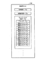
[表示器4の構成例]
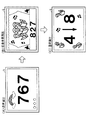
図2は、図1における表示器4の拡大図である。表示器4は、主に特別図柄判定や普通図柄判定に関する情報を表示するものであり、図2に示されるように、第1特別図柄表示器41、第2特別図柄表示器42、第1特別図柄保留表示器43、普通図柄表示器45、普通図柄保留表示器46、および遊技状態表示器47を有して構成されている。
[Configuration Example of Display 4]
FIG. 2 is an enlarged view of the display 4 in FIG. The display 4 mainly displays information related to special symbol determination and normal symbol determination. As shown in FIG. 2, the first special symbol display 41, the second special symbol display 42, and the first special symbol are displayed. It has a symbol hold display 43, a normal symbol display 45, a normal symbol hold display 46, and a game state display 47.
第1特別図柄表示器41は、第1特別図柄判定が行われると、図柄を変動表示してから第1特別図柄判定の判定結果を示す判定図柄を停止表示することによって第1特別図柄判定の判定結果を報知する。この第1特別図柄表示器41には、第1特別図柄判定の結果が大当たり(1種大当たり)であることを示す大当たり図柄、または第1特別図柄判定の結果がハズレであることを示すハズレ図柄が停止表示される。
When the first special symbol determination is performed, the first special symbol display 41 displays the determination symbol indicating the determination result of the first special symbol determination after variably displaying the symbol, thereby displaying the first special symbol determination. The determination result is notified. The first special symbol display 41 has a jackpot symbol indicating that the result of the first special symbol determination is a big hit (1 type big hit), or a lost symbol indicating that the result of the first special symbol determination is a loss. Is stopped.
第2特別図柄表示器42は、第2特別図柄判定が行われると、図柄を変動表示してから第2特別図柄判定の判定結果を示す判定図柄を停止表示することによって第2特別図柄判定の判定結果を報知する。この第2特別図柄表示器42には、第2特別図柄判定の結果が大当たり(1種大当たり)であることを示す大当たり図柄、第2特別図柄判定の結果が小当たりであることを示す小当たり図柄、または第2特別図柄判定の結果がハズレであることを示すハズレ図柄が停止表示される。
When the second special symbol determination is performed, the second special symbol display 42 displays the determination symbol indicating the determination result of the second special symbol determination after variably displaying the symbol, thereby displaying the second special symbol determination. The determination result is notified. The second special symbol display 42 has a jackpot symbol indicating that the result of the second special symbol determination is a jackpot (1 type jackpot), and a small hit indicating that the result of the second special symbol determination is a jackpot The losing symbol indicating that the symbol or the result of the second special symbol determination is losing is stopped and displayed.
ところで、特別図柄判定に係る図柄の変動表示中や特別遊技中に第1始動口11に新たに遊技球が入賞した場合、この入賞を契機とする第1特別図柄判定および図柄の変動表示を即座に実行することができない。そこで、本実施形態におけるパチンコ遊技機1は、第1始動口11に遊技球が入賞しても即座に第1特別図柄判定を実行できない場合に、第1特別図柄判定の権利が保留されるように構成されている。第1特別図柄保留表示器43は、このようにして保留された第1特別図柄判定の保留数を表示する。
By the way, when a game ball is newly won at the first starting port 11 during the symbol variation display related to the special symbol determination or during the special game, the first special symbol determination and the symbol variation display are immediately triggered by this winning. Can not be executed. Therefore, the pachinko gaming machine 1 according to the present embodiment seems to hold the right of the first special symbol determination when the first special symbol determination cannot be immediately executed even if a game ball wins the first starting port 11. It is configured. The first special symbol hold indicator 43 displays the number of hold of the first special symbol determination held in this way.
なお、パチンコ遊技機1では、第2始動口12に遊技球が入賞しても第2特別図柄判定を即座に実行できない場合、すなわち特別図柄判定に係る図柄の変動表示中や特別遊技中に第2始動口12に新たに遊技球が入賞した場合には、第2特別図柄判定は実行されず、また、第2特別図柄判定の権利が保留されることもない。このため、表示器4には、第2特別図柄判定の保留数を表示する表示器は設けられていない。
In the pachinko gaming machine 1, the second special symbol determination cannot be immediately executed even if a game ball wins at the second starting port 12, that is, during the symbol variation display or special game related to the special symbol determination. 2 When a game ball is newly won at the start port 12, the second special symbol determination is not executed, and the right of the second special symbol determination is not suspended. For this reason, the display device 4 is not provided with a display device that displays the number of reserved second symbol determinations.
普通図柄表示器45は、普通図柄判定が行われると、図柄を変動表示してから普通図柄判定の判定結果を示す判定図柄を停止表示することによって普通図柄判定の判定結果を報知する。なお、例えば普通図柄表示器45における図柄の変動表示中など、遊技球がゲート16を通過しても普通図柄判定および普通図柄判定に係る図柄の変動表示を即座に実行できない場合には、普通図柄判定の権利が保留される。普通図柄保留表示器46は、このようして保留された普通図柄判定の保留数を表示する。遊技状態表示器47は、パチンコ遊技機1の電源投入時点における遊技状態を表示する。パチンコ遊技機1の遊技状態については、図4に基づいて後に詳述する。
When the normal symbol determination is performed, the normal symbol display 45 notifies the determination result of the normal symbol determination by suspending and displaying the determination symbol indicating the determination result of the normal symbol determination after variably displaying the symbol. Note that the normal symbol determination and the symbol variation display related to the normal symbol determination cannot be immediately executed even when the game ball passes through the gate 16, such as during the symbol variation display on the normal symbol display 45, the normal symbol is displayed. Judgment rights are withheld. The normal symbol hold display 46 displays the number of hold for normal symbol determination held in this way. The game state display 47 displays the game state at the time when the power of the pachinko gaming machine 1 is turned on. The gaming state of the pachinko gaming machine 1 will be described in detail later based on FIG.
なお、以下の説明では、第1特別図柄表示器41または第2特別図柄表示器42に表示される図柄を「特別図柄」と呼び、普通図柄表示器45に表示される図柄を「普通図柄」と呼ぶものとする。
In the following description, the symbol displayed on the first special symbol display 41 or the second special symbol display 42 is called “special symbol”, and the symbol displayed on the normal symbol display 45 is “normal symbol”. Shall be called.
[特定領域9の構成例]
図3は、特定領域9の内部構造を示す模式図である。図3における鉛直方向34および幅方向35は、図1における鉛直方向34および幅方向35と対応しており、それぞれ、パチンコ遊技機1の鉛直方向と幅方向を示している。特定領域9は、小当たりが発生することによって遊技球が進入可能に開放される領域であり、その入口である特定入賞口19には、特定入賞口19を開閉する羽根部材90が設けられている。
[Configuration Example of Specific Area 9]
FIG. 3 is a schematic diagram showing the internal structure of the specific region 9. The vertical direction 34 and the width direction 35 in FIG. 3 correspond to the vertical direction 34 and the width direction 35 in FIG. 1, and indicate the vertical direction and the width direction of the pachinko gaming machine 1, respectively. The specific area 9 is an area where the game ball is opened so as to be able to enter when a small hit occurs, and a blade member 90 that opens and closes the specific prize opening 19 is provided in the specific prize opening 19 that is the entrance. Yes.
本実施形態におけるパチンコ遊技機1では、第1特別図柄表示器41または第2特別図柄表示器42に特別図柄判定の結果が「大当たり」であることを示す大当たり図柄が判定図柄として停止表示されると、1種大当たりとなって第1特別遊技が実行される。
In the pachinko gaming machine 1 according to the present embodiment, a jackpot symbol indicating that the result of the special symbol determination is “big hit” is stopped and displayed as a determination symbol on the first special symbol display 41 or the second special symbol display 42. And, the first special game is executed with one kind of big hit.
なお、本実施形態では、第1特別遊技として、長当たり遊技と短当たり遊技の2種類の特別遊技が設けられている。ここで、長当たり遊技は、所定条件(例えば大入賞口13への9個の遊技球の入賞、または大入賞口13が開放されてから29秒が経過)を満たすまで大入賞口13を開放した状態を維持した後に大入賞口13を閉塞する長開放ラウンド遊技を規定回数実行するものである。本実施形態では、1種大当たりに対する長当たり遊技として、長開放ラウンド遊技が4回実行される4R長当たり遊技と、長開放ラウンド遊技が7回実行される7R長当たり遊技との2種類の長当たり遊技が設けられている。一方の短当たり遊技は、大入賞口13を開放してから所定時間(例えば0.2秒)が経過するまで大入賞口13を開放した状態を維持した後に大入賞口13を閉塞する短開放ラウンド遊技を規定回数(例えば15回)実行する15R短当たり遊技である。
In the present embodiment, as the first special game, two types of special games, a long hit game and a short hit game, are provided. Here, the long winning game opens the grand prize opening 13 until a predetermined condition (for example, winning of nine game balls into the big prize opening 13 or 29 seconds have passed since the grand prize opening 13 is opened) is satisfied. The long open round game that closes the special winning opening 13 after the maintained state is maintained is executed a prescribed number of times. In the present embodiment, two types of long games, 4R long games where long open round games are executed four times and 7R long games where long open round games are executed seven times, are games per long for one kind of big hit. A winning game is provided. On the other hand, the short win game is a short opening which closes the big winning opening 13 after maintaining the opened state until the predetermined time (for example, 0.2 seconds) elapses after the big winning opening 13 is opened. This is a 15R short hit game in which a round game is executed a specified number of times (for example, 15 times).
これに対して、第2特別図柄表示器42に第2特別図柄判定の結果が「小当たり」であることを示す小当たり図柄が判定図柄として停止表示されると、羽根部材90を作動させて特定領域9を開放する小当たり遊技が実行される。この小当たり遊技では、特定領域9を開放してから所定時間(例えば3.2秒)が経過するまで特定領域9を開放した状態を維持した後に特定領域9を閉塞する羽根部材90の動作が規定回数(例えば1回)実行される。このように、小当たりが発生することで、特定領域9への遊技球の進入が可能になる。
On the other hand, when the small special symbol indicating that the result of the second special symbol determination is “small hit” is stopped and displayed as the determination symbol on the second special symbol display 42, the blade member 90 is operated. A small hit game that opens the specific area 9 is executed. In this small hit game, the operation of the blade member 90 that closes the specific area 9 after maintaining the state in which the specific area 9 is opened until a predetermined time (for example, 3.2 seconds) elapses after the specific area 9 is opened. It is executed a prescribed number of times (for example, once). In this way, when the small hit occurs, the game ball can enter the specific area 9.
図3に示されるように、特定領域9には、案内部材91、V入賞口92、ハズレ入賞口93、およびスライド部材94が設けられている。案内部材91は、特定入賞口19から特定領域9に進入した遊技球をV入賞口92またはハズレ入賞口93へと案内するものである。V入賞口92またはハズレ入賞口93に遊技球が入賞した場合、所定数の賞球が払い出される。ハズレ入賞口93が常時開放されているのに対して、V入賞口92は、通常はスライド部材94によって閉塞されており、特定入賞口19が開放された後の所定期間だけ開放される。具体的には、本実施形態では、特定入賞口19が開放されてから例えば0.5秒後にスライド部材94がスライドしてV入賞口92が開放され、V入賞口92の開放から0.2秒が経過するとスライド部材94が図3に示される元の位置に戻ってV入賞口92が閉塞される。
As shown in FIG. 3, the specific region 9 is provided with a guide member 91, a V winning opening 92, a lose winning opening 93, and a slide member 94. The guide member 91 guides the game ball that has entered the specific area 9 from the specific winning opening 19 to the V winning opening 92 or the lost winning opening 93. When a game ball wins the V winning opening 92 or the lose winning opening 93, a predetermined number of winning balls are paid out. The lose prize opening 93 is always open, whereas the V prize opening 92 is normally closed by the slide member 94 and is opened only for a predetermined period after the specific prize opening 19 is opened. Specifically, in this embodiment, for example, 0.5 seconds after the specific winning opening 19 is opened, the slide member 94 slides to open the V winning opening 92, and 0.2 V from the opening of the V winning opening 92. When the second elapses, the slide member 94 returns to the original position shown in FIG. 3, and the V winning opening 92 is closed.
そして、このV入賞口92の開放期間にV入賞口92に遊技球が入賞(V入賞)することで、2種大当たりが発生し、既に行われた小当たり遊技を含む第2特別遊技が実行される。すなわち、2種大当たりが発生した場合、小当たり遊技に続いて長当たり遊技が実行される。具体的には、特定領域9を3.2秒間だけ開放する小当たり遊技に続いて、大入賞口13を長開放する3回の長開放ラウンド遊技からなる長当たり遊技、または大入賞口13を長開放する14回の長開放ラウンド遊技からなる長当たり遊技が実行される。すなわち、1回の小当たり遊技と3回の長開放ラウンド遊技とを含む計4Rの特別遊技、または1回の小当たり遊技と14回の長開放ラウンド遊技とを含む計15Rの特別遊技が実行される。
Then, when a game ball wins (V winning) in the V winning opening 92 during the open period of the V winning opening 92, two kinds of big wins are generated, and the second special game including the already played small winning game is executed. Is done. That is, when two types of big hits occur, the long hit game is executed following the small hit game. Specifically, following the small hit game in which the specific area 9 is opened for 3.2 seconds, the long win game consisting of three long open round games in which the big winning opening 13 is opened long, or the big winning opening 13 is set. A long hit game consisting of 14 long open round games that are long open is executed. That is, a total of 4R special games including one small hit game and three long open round games, or a total of 15R special games including one small hit game and 14 long open round games are executed. Is done.
このように、1種大当たりによる特別遊技では大入賞口13のみを開放するラウンド遊技から構成される第1特別遊技が実行されるのに対して、2種大当たりによる特別遊技では特定領域9を開放する小当たり遊技と大入賞口13を開放するラウンド遊技とから構成される第2特別遊技が実行される。なお、V入賞口92の開放期間中に遊技球がV入賞口92に入賞しなかった場合、小当たり遊技に続いて大入賞口13が開放されることはないため、第2特別遊技は小当たり遊技のみの1Rで終了することになる。
As described above, in the special game based on the 1st type jackpot, the first special game composed of the round game in which only the winning prize opening 13 is opened, whereas in the special game based on the 2nd type jackpot, the specific area 9 is opened. A second special game composed of a small hit game and a round game that opens the big prize opening 13 is executed. Note that if the game ball does not win the V winning opening 92 during the opening period of the V winning opening 92, the big winning opening 13 will not be opened following the small hit game, so the second special game is small. It will end with 1R of only winning games.
なお、本実施形態では、V入賞口92がスライド部材94によって開閉される場合について説明するが、パチンコ遊技機1の奥行方向を軸方向として回動する羽根部材によってV入賞口92を開閉するようにしてもよい。また、1回の小当たり遊技中の羽根部材90の動作パターン(特定入賞口19を開放する時間および回数)等も適宜変更可能である。
In this embodiment, the case where the V winning opening 92 is opened and closed by the slide member 94 will be described. However, the V winning opening 92 is opened and closed by a blade member that rotates about the depth direction of the pachinko gaming machine 1 as an axial direction. It may be. In addition, the operation pattern of the blade member 90 during one small hit game (time and number of times of opening the specific winning opening 19) and the like can be appropriately changed.
[遊技状態の変化の説明]
次に、図4を参照しつつ、パチンコ遊技機1の遊技状態について説明する。ここで、図4は、大当たりと遊技状態について説明するための説明図である。図4に示されるように、本実施形態におけるパチンコ遊技機1は、「通常遊技状態」または「時短遊技状態」にて遊技が制御される。
[Description of changes in gaming state]
Next, the gaming state of the pachinko gaming machine 1 will be described with reference to FIG. Here, FIG. 4 is an explanatory diagram for explaining the jackpot and the gaming state. As shown in FIG. 4, in the pachinko gaming machine 1 according to the present embodiment, the game is controlled in the “normal game state” or the “time-saving game state”.
「通常遊技状態」は、いわゆる電チューサポート機能が付与されない通常の遊技状態である。「通常遊技状態」は、具体的には、第2始動口12を開放すると普通図柄判定において判定される割合が所定の割合(例えば12/12)に設定され、普通図柄の変動時間が相対的に長い時間(例えば25秒)に設定され、かつ第2始動口12を開放すると判定された場合の第2始動口12の開放時間が相対的に短い時間(例えば0.1秒×1回)に設定される遊技状態である。
The “normal game state” is a normal game state in which a so-called electric chew support function is not given. Specifically, in the “normal game state”, when the second start port 12 is opened, the ratio determined in the normal symbol determination is set to a predetermined ratio (for example, 12/12), and the variation time of the normal symbol is relative. Is set to a long time (for example, 25 seconds), and when it is determined that the second starting port 12 is to be opened, the opening time of the second starting port 12 is relatively short (for example, 0.1 second × 1 time). It is a gaming state set to.
「時短遊技状態」は、電チューサポート機能が付与される遊技状態である。「時短遊技状態」は、具体的には、第2始動口12を開放すると普通図柄判定において判定される割合が通常遊技状態のときと同じ所定の割合(例えば12/12)に設定され、普通図柄の変動時間が相対的に短い時間(例えば2.5秒)に設定され、かつ第2始動口12を開放すると判定された場合の第2始動口12の開放時間が相対的に長い時間(例えば0.3秒×5回)に設定される遊技状態である。すなわち、「時短遊技状態」は、通常遊技状態に比べて、第2始動口12が開放状態に制御され易い遊技状態である。
The “time saving gaming state” is a gaming state to which an electric chew support function is provided. Specifically, in the “short-time gaming state”, when the second start port 12 is opened, the ratio determined in the normal symbol determination is set to the same predetermined ratio (for example, 12/12) as in the normal gaming state. When the design variation time is set to a relatively short time (for example, 2.5 seconds) and the second start port 12 is determined to be opened, the open time of the second start port 12 is relatively long ( For example, the gaming state is set to 0.3 seconds × 5 times. In other words, the “short-time gaming state” is a gaming state in which the second start port 12 is more easily controlled to the open state than in the normal gaming state.
遊技盤2の盤面構成上、遊技領域10の左側領域に打ち出された遊技球は第1始動口11に入賞可能であるのに対して、遊技領域10の右側領域に打ち出された遊技球が第1始動口11に入賞することはない。また、「通常遊技状態」のときには、第2始動口12は開放状態になり難い。このため、「通常遊技状態」のときに右打ちを行うメリットはない。このように、「通常遊技状態」は、遊技球を遊技領域10の左側領域に打ち出した方が右側領域に打ち出すよりも大当たりを引き当てやすい左側有利状態であるため、遊技者は、メイン液晶表示装置5に表示されるメッセージやスピーカ24から出力される音声ガイダンスに従って左打ちを行うことになる。
Due to the board configuration of the game board 2, a game ball launched into the left area of the game area 10 can win the first starting port 11, whereas a game ball launched into the right area of the game area 10 There will never be a prize at the starting port 11. Further, in the “normal game state”, the second start port 12 is not easily opened. For this reason, there is no merit of making a right strike in the “normal game state”. In this way, the “normal game state” is a left-side advantageous state in which it is easier to hit a jackpot than hitting a game ball in the left area of the game area 10 than in the right area. 5 is left-handed according to the message displayed at 5 and the voice guidance output from the speaker 24.
「通常遊技状態」のときに遊技者が左打ちを行って遊技領域10の左側領域に打ち出された遊技球が第1始動口11に入賞すると、第1特別図柄判定が行われ、第1特別図柄表示器41に特別図柄が変動表示された後にその第1特別図柄判定の結果を示す判定図柄が停止表示される。ここで、第1特別図柄判定によって1種大当たりと判定された場合には第1特別図柄表示器41にその旨を示す大当たり図柄が停止表示され、大入賞口13を開放する第1特別遊技が実行される。そして、この第1特別遊技開始時に第1特別図柄表示器41に停止表示されていた大当たり図柄の種類に応じて、第1特別遊技が終了した後に、遊技状態が設定される。本実施形態では、図4に例示されるように、第1特別遊技終了後に50%の割合で「通常遊技状態」が継続される一方で、残りの50%については「通常遊技状態」から「時短遊技状態」へと遊技状態が変化する。
When the player makes a left strike in the “normal game state” and the game ball launched into the left area of the game area 10 wins the first start port 11, the first special symbol determination is performed and the first special symbol is determined. After the special symbol is variably displayed on the symbol display 41, the determination symbol indicating the result of the first special symbol determination is stopped and displayed. Here, when it is determined that the first special symbol is determined to be one type of big win, the first special symbol display 41 is stopped and the big special symbol indicating that is stopped and the first special game that opens the special winning opening 13 is performed. Executed. Then, the game state is set after the first special game is ended according to the type of jackpot symbol that is stopped and displayed on the first special symbol display 41 at the start of the first special game. In the present embodiment, as illustrated in FIG. 4, the “normal game state” is continued at a rate of 50% after the first special game is finished, while the remaining 50% is changed from “normal game state” to “ The gaming state changes to “short-time gaming state”.
本実施形態では、第1特別遊技終了後に通常遊技状態にて遊技が制御されることになる時短無し当たりとして、図4に例示されるように、7回の長開放ラウンド遊技が行われた後に通常遊技状態となる時短無し7R当たりが設けられており、1種大当たりの50%がこの時短無し7R当たりとなる。また、第1特別遊技終了後に時短遊技状態にて遊技が制御されることになる時短付き当たりとして、4回の長開放ラウンド遊技が行われた後に時短遊技状態となる時短付き4R当たり、15回の短開放ラウンド遊技が行われた後に時短遊技状態となる突然時短当たりの2種類が設けられており、1種大当たりの50%がこれら2種類の時短付き当たりのいずれかとなる。
In the present embodiment, after the first special game is completed, the game is controlled in the normal gaming state, and as shown in FIG. 4, after the seven long open round games are performed as illustrated in FIG. There is a short per 7R when the normal gaming state is entered, and 50% of the one type large per 7R per short at this time. In addition, 15 times per 4R with time reduction that becomes short-time game state after four long open round games are performed as per time-short game where the game will be controlled in short-time game state after the end of the first special game. There are two types of short-acting short-term games that become short-time game states after the short-opening round game is completed, and 50% of the one-type game is one of these two types of short-timed games.
遊技状態が「時短遊技状態」に移行すると、「通常遊技状態」のときに比べて第2始動口12が開放状態になり易くなる。その上、第2始動口12に遊技球が入賞することを条件として実行される第2特別図柄判定の結果の大半が小当たりとなるため、2種大当たりが発生し易い。このように、「時短遊技状態」は、遊技球を遊技領域10の右側領域に打ち出した方が左側領域に打ち出すよりも大当たりを引き当てやすい右側有利状態であるため、遊技者は、メイン液晶表示装置5に表示されるメッセージやスピーカ24から出力される音声ガイダンスに従って右打ちを行うことになる。
When the gaming state shifts to the “time-saving gaming state”, the second start port 12 is more likely to be in the open state than in the “normal gaming state”. In addition, since most of the results of the second special symbol determination executed on condition that a game ball wins the second starting port 12 is a small hit, two types of big hits are likely to occur. As described above, the “short-time gaming state” is a right-side advantageous state in which a player hits a game ball in the right region of the game region 10 more easily than hitting the left region, so the player can play the main liquid crystal display device. 5 is performed in accordance with the message displayed on the screen 5 and the voice guidance output from the speaker 24.
「時短遊技状態」のときに遊技者が右打ちを行って遊技領域10の右側領域に打ち出された遊技球がゲート16を通過すると、普通図柄判定が行われる。「時短遊技状態」のときに普通図柄判定が行われて第2始動口12を開放すると判定された場合、第2始動口12の開放時間が「通常遊技状態」のときに比べて長いので、遊技領域10の右側領域に打ち出された遊技球は、第2始動口12に容易に入賞する。
When the player makes a right strike in the “short-time gaming state” and the game ball launched into the right area of the game area 10 passes through the gate 16, normal symbol determination is performed. When it is determined that the second starting port 12 is opened when the normal symbol determination is performed in the “short-time gaming state”, the opening time of the second starting port 12 is longer than that in the “normal gaming state”. A game ball launched into the right area of the game area 10 easily wins the second starting port 12.
「時短遊技状態」において、特別図柄が変動表示されておらず、かつ特別遊技中でないときに第2始動口12に遊技球が入賞すると、第2特別図柄判定が行われ、第2特別図柄表示器42に特別図柄が変動表示された後にその第2特別図柄判定の結果を示す判定図柄が停止表示される。ここで、第2特別図柄判定によって小当たりと判定された場合には第2特別図柄表示器42にその旨を示す小当たり図柄が停止表示され、特定領域9およびV入賞口92を一時的に開放する小当たり遊技が実行され、この小当たり遊技中に遊技球がV入賞口92に入賞することで2種大当たりとなって、当該小当たり遊技を含む第2特別遊技が実行される。そして、この小当たり遊技のときに第2特別図柄表示器42に停止表示されていた小当たり図柄の種類に応じて、第2特別遊技が終了した後に、遊技状態が設定される。本実施形態では、図4に例示されるように、第2特別遊技終了後に70%の割合で「時短遊技状態」が継続される一方で、残りの30%については「時短遊技状態」から「通常遊技状態」に戻されることになる。
In the “short time gaming state”, when the special symbol is not variably displayed and the game ball is won at the second starting port 12 when the special game is not being performed, the second special symbol determination is performed and the second special symbol display is performed. After the special symbol is variably displayed on the device 42, the determination symbol indicating the result of the second special symbol determination is stopped and displayed. Here, when it is determined that a small winning is determined by the second special symbol determination, the small special symbol indicating that is stopped and displayed on the second special symbol display 42, and the specific area 9 and the V winning opening 92 are temporarily displayed. The small hit game to be opened is executed, and the game ball is won in the V winning opening 92 during the small hit game, so that two kinds of big hits are made, and the second special game including the small hit game is executed. Then, the game state is set after the second special game is ended according to the type of the small hit symbol stopped and displayed on the second special symbol display 42 at the time of the small hit game. In the present embodiment, as illustrated in FIG. 4, the “short-time gaming state” is continued at a rate of 70% after the second special game is completed, while the remaining 30% is “from the short-time gaming state” to “ It will be returned to the “normal gaming state”.
本実施形態では、第2特別遊技終了後に通常遊技状態にて遊技が制御されることになる時短無し当たりとして、図4に例示されるように、1回の小当たり遊技と3回の長開放ラウンド遊技とが行われた後に通常遊技状態となる時短無し4R当たりが設けられており、2種大当たりの30%がこの時短無し4R当たりとなる。また、第2特別遊技終了後に時短遊技状態にて遊技が制御されることになる時短付き当たりとして、1回の小当たり遊技と14回の長開放ラウンド遊技とが行われた後に時短遊技状態となる時短付き15R当たり、1回の小当たり遊技と3回の長開放ラウンド遊技とが行われた後に時短遊技状態となる時短付き4R当たりの2種類が設けられており、2種大当たりの70%がこれら2種類の時短付き当たりのいずれかとなる。
In the present embodiment, as a short hit per hour when the game is to be controlled in the normal game state after the end of the second special game, as shown in FIG. 4, one small hit game and three long open games There is a short time 4R per game that is in a normal gaming state after a round game is performed, and 30% of the two kinds of big time is per short 4R at this time. In addition, after the second special game, the game will be controlled in the short-time game state. As the short-time game, after one small hit game and 14 long open round games are performed, There are 2 types per 4R with a short time after a small hit game and 3 long open round games are performed per 15R with a short time, 70% per 2 types Is one of these two types of time savings.
なお、詳細な説明は省略するが、「時短遊技状態」において100回の第2特別図柄判定が行われても2種大当たりが発生しなかった場合にも、遊技状態が「時短遊技状態」から「通常遊技状態」に戻されることになる。
In addition, although detailed explanation is omitted, even if the second special symbol determination is performed 100 times in the “short-time gaming state” and the two types of big wins are not generated, the gaming state is changed from the “short-time gaming state”. It will be returned to the “normal game state”.
[パチンコ遊技機1の演出手段の構成例]
図1に示されるように、遊技盤2または枠部材3には、各種の演出を行うものとして、メイン液晶表示装置5、サブ液晶表示装置6、ロゴ役物7、スピーカ24、および枠ランプ25が設けられている。
[Configuration example of presentation means of pachinko gaming machine 1]
As shown in FIG. 1, the game board 2 or the frame member 3 has various functions such as a main liquid crystal display device 5, a sub liquid crystal display device 6, a logo accessory 7, a speaker 24, and a frame lamp 25. Is provided.
メイン液晶表示装置5は、演出画像を表示する液晶表示画面を有する画像表示装置であり、遊技者によって視認され易い位置に固設されている。メイン液晶表示装置5の表示画面には、例えば、特別図柄判定の結果を報知する装飾図柄、予告演出などを行うキャラクタやアイテム、第1特別図柄判定が保留されていることを示す保留表示画像等の各種表示オブジェクトを含む演出画像が表示される。
The main liquid crystal display device 5 is an image display device having a liquid crystal display screen for displaying effect images, and is fixedly installed at a position where it can be easily seen by the player. The display screen of the main liquid crystal display device 5 includes, for example, a decorative symbol for notifying the result of the special symbol determination, a character or item for performing a notice effect, a hold display image indicating that the first special symbol determination is held, and the like. The effect image including the various display objects is displayed.
サブ液晶表示装置6は、演出画像を表示する液晶表示画面を有する画像表示装置であり、メイン液晶表示装置5の上方に移動可能に設けられている。サブ液晶表示装置6の表示画面としては、メイン液晶表示装置5の表示画面に比べて小さいものが用いられる。
The sub liquid crystal display device 6 is an image display device having a liquid crystal display screen for displaying an effect image, and is provided movably above the main liquid crystal display device 5. The display screen of the sub liquid crystal display device 6 is smaller than the display screen of the main liquid crystal display device 5.
なお、本実施形態では、メイン液晶表示装置5およびサブ液晶表示装置6が共に液晶表示装置によって構成されている場合について説明するが、これらの両方またはどちらか一方が例えばEL表示装置等の他の画像表示装置によって構成されてもよい。
In the present embodiment, a case where both the main liquid crystal display device 5 and the sub liquid crystal display device 6 are configured by a liquid crystal display device will be described. However, both or one of them is another type such as an EL display device. You may comprise by an image display apparatus.
ロゴ役物7は、サブ液晶表示装置6に対して可動に構成されており、サブ液晶表示装置6に遊技者の視線を誘導することを目的として、サブ液晶表示装置6において所定の演出が表示されるのに先立って振動したり回転したりするように動作する。
The logo accessory 7 is configured to be movable with respect to the sub liquid crystal display device 6, and a predetermined effect is displayed on the sub liquid crystal display device 6 for the purpose of guiding the player's line of sight to the sub liquid crystal display device 6. Operates to vibrate and rotate prior to being done.
スピーカ24は、メイン液晶表示装置5および/またはサブ液晶表示装置6で行われる表示演出と同期するように楽曲や音声、効果音等を出力して音による演出を行う。枠ランプ25は、発光色や発光パターン、光の放射方向を変化させることによって光による演出を行う。
The speaker 24 produces a sound effect by outputting music, sound, sound effects, etc. in synchronism with the display effect performed in the main liquid crystal display device 5 and / or the sub liquid crystal display device 6. The frame lamp 25 produces an effect by light by changing a light emission color, a light emission pattern, and a light emission direction.
[パチンコ遊技機1の操作手段の構成例]
枠部材3には、遊技者が操作する操作手段として、演出ボタン26および演出キー27が設けられている。演出ボタン26は、遊技者が押下することによって操作情報を入力するための押ボタンである。演出キー27は、上下左右のいずれかの方向を指示するためのいわゆる十字キーである。パチンコ遊技機1では、演出ボタン26または演出キー27から入力された操作情報に応じた演出が行われる場合がある。
[Configuration example of operation means of the pachinko gaming machine 1]
The frame member 3 is provided with an effect button 26 and an effect key 27 as operation means operated by the player. The effect button 26 is a push button for inputting operation information when pressed by the player. The effect key 27 is a so-called cross key for instructing one of up, down, left and right directions. In the pachinko gaming machine 1, there is a case where an effect corresponding to the operation information input from the effect button 26 or the effect key 27 is performed.
[パチンコ遊技機1で行われる演出の主な特徴]
以下、図5〜図8を参照しつつ、パチンコ遊技機1において行われる演出の主な特徴について説明する。
[Main features of production performed on pachinko machine 1]
Hereinafter, main features of effects performed in the pachinko gaming machine 1 will be described with reference to FIGS.
図5は、複数台のパチンコ遊技機1が設置された遊技システムの模式図である。図5に例示されるように、いわゆるパチンコホールには、上述したパチンコ遊技機1が複数台(例えば20台)並べて設置されることによって1つの島が構成される。この島に設置された各パチンコ遊技機1は、共通の島電源ラインを介して島電源供給装置500と電気的に接続される。このため、各パチンコ遊技機1の個別電源スイッチを「ON」にした状態で島電源供給装置500の電源を投入することで、1つの島に設置された複数台のパチンコ遊技機1を一斉に起動させることができる。本実施形態におけるパチンコ遊技機1は、このような起動方法を利用して、同じ島に設置された全てのパチンコ遊技機1において一斉に同じ演出を開始することを可能にする構成を備えている。
FIG. 5 is a schematic diagram of a gaming system in which a plurality of pachinko gaming machines 1 are installed. As illustrated in FIG. 5, in the so-called pachinko hall, one island is configured by arranging a plurality (for example, 20) of the above-described pachinko gaming machines 1 side by side. Each pachinko machine 1 installed on this island is electrically connected to the island power supply device 500 through a common island power supply line. Therefore, by turning on the power of the island power supply device 500 with the individual power switch of each pachinko gaming machine 1 set to “ON”, a plurality of pachinko gaming machines 1 installed on one island can be combined. Can be activated. The pachinko gaming machine 1 in the present embodiment has a configuration that makes it possible to start the same presentation at once in all the pachinko gaming machines 1 installed on the same island using such a startup method. .
図6は、メイン液晶表示装置5を用いて行われる演出の流れについて説明するための画面図である。例えば「通常遊技状態」のときに第1始動口11に遊技球が入賞して第1特別図柄判定が行われた場合、メイン液晶表示装置5の表示画面には、第1特別図柄表示器41に特別図柄が表示されるのに伴って装飾図柄が変動表示された後に、第1特別図柄表示器41に判定図柄が停止表示されるタイミングで第1特別図柄判定の結果を示す装飾図柄が停止表示される(図6(A)参照)。このように装飾図柄を変動表示させる際には、メイン液晶表示装置5および/またはサブ液晶表示装置6を用いて様々な演出が行われる。また、パチンコ遊技機1が所定の遊技状態にある場合、当該遊技状態であることを示す演出がメイン液晶表示装置5および/またはサブ液晶表示装置6を用いて行われる。他の演出と区別するために、パチンコ遊技機1において、遊技球を用いた遊技の状況に応じて行われるこのような演出を、通常演出と記載する。通常演出が行われる際は、遊技媒体としての遊技球を用いた遊技に伴って、メイン液晶表示装置5および/またはサブ液晶表示装置6やスピーカ24、枠ランプ25等を用いた演出が実行される。
FIG. 6 is a screen diagram for explaining the flow of effects performed using the main liquid crystal display device 5. For example, when the game ball is won at the first starting port 11 and the first special symbol determination is performed in the “normal gaming state”, the first special symbol display 41 is displayed on the display screen of the main liquid crystal display device 5. The decorative symbol indicating the result of the first special symbol determination is stopped at the timing when the determination symbol is stopped and displayed on the first special symbol display 41 after the decorative symbol is variably displayed as the special symbol is displayed. Is displayed (see FIG. 6A). In this way, when the decorative symbols are displayed in a variable manner, various effects are performed using the main liquid crystal display device 5 and / or the sub liquid crystal display device 6. Further, when the pachinko gaming machine 1 is in a predetermined gaming state, an effect indicating that the gaming state is in the gaming state is performed using the main liquid crystal display device 5 and / or the sub liquid crystal display device 6. In order to distinguish from other effects, such effects performed in the pachinko gaming machine 1 according to the game situation using the game ball are referred to as normal effects. When a normal effect is performed, an effect using the main liquid crystal display device 5 and / or the sub liquid crystal display device 6, the speaker 24, the frame lamp 25, and the like is executed along with the game using the game ball as the game medium. The
一方、パチンコ遊技機1では、電源が投入されてからの経過時間を計測する計測処理が行われており、所定の設定時間(本実施形態では約60分)が経過したタイミングで、未公開コンテンツとしての新曲を発表する新曲発表演出(本実施形態では新曲のムービー再生)が開始される(図6(B)参照)。この新曲発表演出は、遊技球を用いた遊技の状況とは無関係に、電源投入から第2設定時間が経過すると強制的に開始される。このため、島電源供給装置500を用いて1つの島に設置された複数台のパチンコ遊技機1を一斉に起動させることで、これらのパチンコ遊技機1において同時に新曲発表演出を開始させることが可能である。
On the other hand, in the pachinko gaming machine 1, a measurement process for measuring an elapsed time since the power is turned on is performed, and unpublished content is reached at a timing when a predetermined set time (about 60 minutes in the present embodiment) has elapsed. The new song announcement effect (in this embodiment, the movie playback of the new song) is started (see FIG. 6B). This new song announcement effect is forcibly started when the second set time elapses after the power is turned on regardless of the game situation using the game ball. For this reason, by using the island power supply device 500 to start a plurality of pachinko gaming machines 1 installed on one island at the same time, it is possible to simultaneously start a new song presentation effect on these pachinko gaming machines 1 It is.
ところで、新曲発表演出は、遊技球を用いた遊技とは無関係に行われる演出であり、新曲発表演出が行われている間も、遊技球を用いた遊技に対する通常演出を行う必要がある。このため、パチンコ遊技機1では、新曲発表演出が開始されてから終了するまでの間、メイン液晶表示装置5の表示画面の上部領域を用いて新曲発表演出が行われる一方で、メイン液晶表示装置5の表示画面の下部領域を用いて通常演出が行われる(図6(C)参照)。なお、本実施形態では、新曲発表演出を際立たせるために、下部領域には、通常演出の装飾図柄等がドット表示される。
By the way, the new song announcement effect is an effect performed irrespective of the game using the game ball, and it is necessary to perform the normal effect for the game using the game ball while the new song announcement effect is being performed. For this reason, in the pachinko machine 1, the new song announcement effect is performed using the upper area of the display screen of the main liquid crystal display device 5 from the start to the end of the new song announcement effect, while the main liquid crystal display device. A normal effect is performed using the lower area of the display screen 5 (see FIG. 6C). In the present embodiment, in order to make the new song announcement effect stand out, a decoration pattern or the like of the normal effect is displayed in dots in the lower area.
新曲発表演出が終了すると、メイン液晶表示装置5の表示画面の下部領域を用いて通常演出が行われていた状態から、表示画面の全体領域を用いて通常演出が行われる状態へと戻る。そして、新曲発表演出が行われた後の通常演出では、新曲発表演出で発表された新曲に基づく演出を行うことが可能となる。すなわち、新曲発表演出開始前の通常演出では使用されていなかった新曲に関する演出データが、新曲発表演出が実行されたことで使用可能となる。
When the new song announcement effect ends, the normal effect is performed using the lower area of the display screen of the main liquid crystal display device 5 and the normal effect is returned using the entire area of the display screen. Then, in the normal performance after the new song announcement effect is performed, it is possible to perform an effect based on the new song announced in the new song announcement effect. In other words, the effect data related to the new song that was not used in the normal effect before the start of the new song announcement effect can be used when the new song announcement effect is executed.
なお、新曲発表演出は、パチンコ遊技機1の電源が投入されてから60分が経過したときにだけ実行される訳ではなく、本実施形態では、パチンコ遊技機1の電源が投入されてから60分が経過する毎に実行される。すなわち、パチンコ遊技機1の電源が投入されてから60分が経過したときに例えば新曲Aの新曲発表演出が実行された場合、60分おきに、新曲Aの新曲発表演出が行われる。また、1つの新曲に対する新曲発表演出は、その新曲の初回の新曲発表演出が実行されてから1週間継続され、次の1週間では、他の新曲の新曲発表が60分おきに実行される。本実施形態におけるパチンコ遊技機1では、このような処理が繰り返されることによって、約3ヶ月間にわたって全12曲の新曲に対する新曲発表演出が実行され、その都度、通常演出で使用可能な演出データが増えて行く。
Note that the new song announcement effect is not executed only when 60 minutes have elapsed since the power of the pachinko gaming machine 1 is turned on. In this embodiment, the new song announcement effect 60 is provided after the power of the pachinko gaming machine 1 is turned on. Runs every minute. That is, when 60 minutes have passed since the power to the pachinko gaming machine 1 is turned on, for example, when a new song announcement effect for new song A is executed, a new song announcement effect for new song A is performed every 60 minutes. Further, the new song announcement effect for one new song is continued for one week after the first new song announcement effect of the new song is executed, and in the next week, new song announcements for other new songs are executed every 60 minutes. In the pachinko gaming machine 1 according to the present embodiment, by repeating such processing, new song announcement effects for all 12 new songs are executed over a period of about three months. It will increase.
図7は、パチンコ遊技機1で行われる新曲発表演出の流れの一例について説明するための説明図である。なお、新曲発表演出の流れを分かり易く示すために、図7においては、午前9時ちょうどにパチンコ遊技機1の電源を投入した場合の時刻が示されている。
FIG. 7 is an explanatory diagram for explaining an example of the flow of a new song announcement effect performed in the pachinko gaming machine 1. In addition, in order to show the flow of the new song announcement effect in an easy-to-understand manner, FIG. 7 shows the time when the power of the pachinko gaming machine 1 is turned on at 9:00 am.
図7(A)に示されるように、パチンコ遊技機1が例えば6/30の土曜日にパチンコホールに導入された場合、導入から1週間が経過するまでは、デフォルトの通常演出が行われる。例えば、新曲発表演出が1回も行われていない状態においてパチンコ遊技機1で行われる通常演出は、デフォルトの演出データを用いて行われる。
As shown in FIG. 7A, when the pachinko gaming machine 1 is introduced into the pachinko hall on Saturday, 6/30, for example, a default normal performance is performed until one week has passed since the introduction. For example, the normal effect performed in the pachinko gaming machine 1 in a state where the new song announcement effect has never been performed is performed using default effect data.
そして、パチンコ遊技機1がパチンコホールに導入されてから1週間が経過した7/7の土曜日に、パチンコ遊技機1の電源が投入されてから3時間が経過したときに、新曲Aの初回新曲発表演出が実行される(図7(B)参照)。図7(B)には、午前9時ちょうどにパチンコ遊技機1の電源が投入されているため、正午ちょうどに新曲Aの初回新曲発表演出が実行され、その後1時間おきに新曲Aの新曲発表演出が実行される例が示されている。
The first new song of the new song A when 3 hours have passed since the power of the pachinko gaming machine 1 was turned on on Saturday, July 7th, one week after the pachinko gaming machine 1 was introduced into the pachinko hall The presentation effect is executed (see FIG. 7B). In FIG. 7 (B), since the power of the pachinko machine 1 is turned on at 9:00 am, the first new song announcement effect of the new song A is executed at exactly noon, and the new song A is announced every hour thereafter. An example in which an effect is executed is shown.
新曲Aの初回新曲発表演出が実行されると、新曲Aに関する演出データを使用する通常演出が可能となる。例えば、装飾図柄を変動表示して特別遊技が行われるか否かを新曲Aに関連する演出によって報知したり、新曲Aのミュージック・ビデオに基づいて作成された演出によってパチンコ遊技機1における遊技状態を報知したりすることによって、新曲Aを用いた通常演出が可能となる。
When the first new song announcement effect of the new song A is executed, a normal effect using the effect data related to the new song A becomes possible. For example, whether or not a special game is to be played by variably displaying decorative symbols is notified by an effect related to the new song A, or a game state in the pachinko gaming machine 1 by an effect created based on the music video of the new song A Or the like, a normal production using the new song A becomes possible.
続いて、新曲Aの初回新曲発表が実行されてから1週間が経過した7/14の土曜日に、パチンコ遊技機1の電源が投入されてから3時間が経過したときに、新曲Bの初回新曲発表演出が実行される(図7(C)参照)。新曲Bの初回新曲発表演出が実行されると、新曲Bに関する演出データを使用する通常演出が可能となる。
Subsequently, on Saturday, July 14th, one week after the announcement of the first song of the new song A, when three hours have passed since the power to the pachinko machine 1 was turned on, the first song of the new song B The presentation effect is executed (see FIG. 7C). When the first new song announcement effect of the new song B is executed, a normal effect using the effect data related to the new song B becomes possible.
このように、各新曲の初回新曲発表演出が実行される毎に使用可能な演出データが増えて行き、当該演出データを用いた通常演出が可能となる。
In this way, every time the first new song announcement effect of each new song is executed, usable effect data increases, and a normal effect using the effect data becomes possible.
なお、図7に例示された新曲発表のスケジュールは一例であって、パチンコ遊技機1の導入初日に新曲Aの初回新曲発表演出を行ったり、同じ新曲の新曲発表演出が実行される時間間隔を60分以外の時間や一定でない時間にしたり、初回新曲発表演出が行われる時間を初回新曲発表日におけるパチンコ遊技機1の電源投入から3時間以外の時間が経過したときにするといった変更を行ってもよいことは言うまでもない。
Note that the new song announcement schedule illustrated in FIG. 7 is an example, and the first new song announcement effect of the new song A is performed on the first day of the introduction of the pachinko machine 1, or the time interval at which the new song announcement effect of the same new song is executed. Change to a time other than 60 minutes, a non-constant time, or a time when the first new song announcement effect is performed when a time other than three hours has passed since the power-on of the pachinko machine 1 on the first new song announcement date Needless to say.
図8は、全ての新曲が発表された後にパチンコ遊技機1で行われる新曲発表演出の流れについて説明するための説明図である。図7(D)に示されるように12曲目の新曲Lの初回新曲発表演出が行われると、その日から1週間が経過した9/29の土曜日からは、1時間毎に行われる新曲発表演出で発表される新曲の種類が順次変化していく(図8参照)。そして、9/29の土曜日には電源投入から1時間が経過したときに新曲Aの新曲発表演出が行われるのに対して、9/30の日曜日には電源投入から1時間が経過したときには新曲Bの新曲発表演出が行われ、10/1の月曜日には電源投入から1時間が経過したときには新曲Cの新曲発表演出が行われるというように、同じ時間帯であっても、日によって発表される新曲の種類が変化する。なお、新曲が発表された各時間帯においては、当該時間帯に発表された新曲に関する演出データを用いた通常演出が、他の新曲に関する演出データを用いた通常演出より選択されやすいように調整してもかまわない。
FIG. 8 is an explanatory diagram for explaining the flow of a new song announcement effect performed in the pachinko machine 1 after all new songs have been announced. As shown in FIG. 7D, when the first new song announcement effect of the twelfth new song L is performed, the new song announcement effect is performed every hour from 9/29 Saturday after one week has passed since that day. The types of new songs to be announced will change sequentially (see Fig. 8). And on Saturday, 9/29, when 1 hour has passed since the power was turned on, the new song A was announced. On Sunday, September 30, the new song was presented when 1 hour had passed since the power was turned on. B's new song announcement effect is performed, and on 1/10 Monday, when 1 hour has passed since the power is turned on, a new song C new song announcement effect is performed. The type of new song changes. In each time zone when a new song is announced, adjustments are made so that the normal performance using the production data related to the new song released during that time zone is easier to select than the normal production using the production data related to other new songs. It doesn't matter.
このように、全ての新曲が発表された後においては、新曲Aの初回新曲発表演出が行われてから新曲Lの1週間の新曲発表演出が完了するまでは毎週遊技しなければ楽しむことができなかった全曲の新曲発表演出や全曲に関する演出データを用いた通常演出を、1日で楽しむことができる。
In this way, after all the new songs have been announced, the new song A can be enjoyed without playing every week from the first new song announcement production of the new song A until the completion of the new song announcement production of the new song L for one week. It is possible to enjoy the normal production using the new song announcement production of all the songs that were not present and production data related to all the songs in one day.
また、同じ時間帯であっても日によって発表される新曲や新曲を用いた通常演出の種類が変化するので、ある時間帯にしか遊技できない遊技者であっても、様々な種類の新曲発表演出や通常演出を楽しむことができる。
Also, even if the player can play only during a certain time period, various types of new song announcement effects will be available, because the types of new performances that are announced by day and the type of normal performance using new songs will change even during the same time period. You can enjoy normal production.
[パチンコ遊技機1で行われる変動演出の主な特徴]
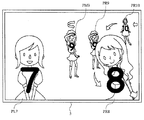
以下、図9〜図13を参照して、パチンコ遊技機1において行われる変動演出の一例について説明する。なお、図9は、パチンコ遊技機1において変動演出が行われる際にメイン液晶表示装置5に表示される装飾図柄画像の第1の状態の一例を示す図である。図10は、パチンコ遊技機1において変動演出が行われる際にメイン液晶表示装置5に表示される装飾図柄画像の第2の状態の一例を示す図である。図11は、パチンコ遊技機1において変動演出が行われる際にメイン液晶表示装置5に表示される装飾図柄画像の第3の状態の一例を示す図である。図12は、装飾図柄画像に含まれる人物画像の構成の一例を示す図である。図13は、人物画像にリング装飾を施して装飾図柄画像を生成する一例を示す図である。
[Main features of variable production performed in pachinko machine 1]
Hereinafter, with reference to FIGS. 9 to 13, an example of a variation effect performed in the pachinko gaming machine 1 will be described. FIG. 9 is a diagram illustrating an example of a first state of a decorative symbol image displayed on the main liquid crystal display device 5 when a variation effect is performed in the pachinko gaming machine 1. FIG. 10 is a diagram illustrating an example of a second state of the decorative symbol image displayed on the main liquid crystal display device 5 when the variation effect is performed in the pachinko gaming machine 1. FIG. 11 is a diagram illustrating an example of a third state of the decorative symbol image displayed on the main liquid crystal display device 5 when the variation effect is performed in the pachinko gaming machine 1. FIG. 12 is a diagram illustrating an example of a configuration of a person image included in a decorative design image. FIG. 13 is a diagram illustrating an example of generating a decorative symbol image by applying ring decoration to a person image.
例えば、パチンコ遊技機1では、表示画面(例えば、メイン液晶表示装置5やサブ液晶表示装置6の表示画面)に複数(例えば、3つ)の装飾図柄画像を変動表示させた後に、大当たり抽選の結果を示す装飾図柄画像を停止表示させることによって、当該抽選結果が報知される。一例として、同じ装飾図柄画像が並ぶ(例えば、装飾図柄「7」が3つ縦または横に並ぶ)ように停止表示させることによって、抽選結果が大当たりであることが報知される。
For example, in the pachinko gaming machine 1, after a plurality of (for example, three) decorative symbol images are variably displayed on a display screen (for example, the display screen of the main liquid crystal display device 5 or the sub liquid crystal display device 6), The lottery result is notified by stopping and displaying the decorative design image indicating the result. As an example, the fact that the same lottery result is a big hit is notified by stopping and displaying so that the same decorative design images are arranged (for example, three decorative designs “7” are arranged vertically or horizontally).
例えば、図9に示すように、本実施形態で用いられる装飾図柄画像は、複数種の識別図柄画像と、それぞれの識別図柄画像に付随する実画像とを組み合わせて構成される。ここで、識別図柄画像は、数字、文字、記号等を表す図柄画像であり、複数の識別図柄画像全て(例えば、3つの識別図柄画像)が停止表示された場合に、停止表示された数字、文字、記号等の並びによって大当たり抽選結果が報知される。識別図柄画像に付随する実画像は、例えば人物等が実写された静止画像または動画像(人物画像)で生成される。そして、識別図柄画像毎に異なる人物を表す実画像を付随することによって、1つの装飾図柄画像が構成される。
For example, as shown in FIG. 9, the decorative symbol image used in the present embodiment is configured by combining a plurality of types of identification symbol images and actual images associated with the identification symbol images. Here, the identification symbol image is a symbol image representing numbers, characters, symbols, and the like. When all of the plurality of identification symbol images (for example, three identification symbol images) are stopped and displayed, The jackpot lottery result is notified by the arrangement of characters, symbols and the like. The real image accompanying the identification symbol image is generated, for example, as a still image or a moving image (person image) in which a person is photographed. Then, by attaching a real image representing a different person for each identification symbol image, one decorative symbol image is configured.
例えば、メイン液晶表示装置5等の表示画面には、仮想空間が表現されており、装飾図柄画像を変動表示する際、それぞれ異なる空間において移動表示および/または回転表示することによって、複数の図柄列が表現される。一例として、表示画面において向かって左側で変動表示する左装飾図柄画像PLは、当該表示画面の左側領域を用いて、上記仮想空間の左奥から表示領域内に出現して左手前まで移動した後に表示領域外へ移動する左図柄列(図9における左装飾図柄画像PL7〜9)を形成する。表示画面において向かって右側で変動表示する右装飾図柄画像PRは、当該表示画面の右側領域を用いて、上記仮想空間の右奥から表示領域内に出現して右手前まで移動した後に表示領域外へ移動する右図柄列(図9における右装飾図柄画像PR9〜11)を形成する。そして、表示画面の中央で変動表示する中装飾図柄画像PMは、当該表示画面の中央領域を用いて、上記仮想空間の中央奥で表示領域内に出現してその位置で回転した後に消滅する中図柄列(図9における中装飾図柄画像PM7)を形成する。なお、図9から明らかなように、左装飾図柄画像PLおよび右装飾図柄画像PRは、上記仮想空間の奥側から手前側へ移動するように変動表示されるため、表示領域内に出現した後、漸増的に拡大表示されることになり、それら一部が表示領域外へ徐々に外れた後に画像全体が表示領域外へ移動する。
For example, a virtual space is expressed on the display screen of the main liquid crystal display device 5 or the like, and when a decorative symbol image is displayed in a variable manner, a plurality of symbol sequences are displayed by moving and / or rotating in different spaces. Is expressed. As an example, the left decorative design image PL that is variably displayed on the left side on the display screen appears in the display area from the left back of the virtual space and moves to the left front using the left area of the display screen. A left symbol sequence (left decorative symbol images PL7 to PL9 in FIG. 9) that moves outside the display area is formed. The right decorative design image PR that is variably displayed on the right side on the display screen appears outside the display area after appearing in the display area from the right back of the virtual space and moving to the right side using the right area of the display screen. The right symbol sequence (right decorative symbol images PR9 to 11 in FIG. 9) is formed. Then, the medium decorative symbol image PM that is variably displayed at the center of the display screen appears in the display area at the center back of the virtual space and disappears after rotating at that position using the center area of the display screen. A symbol row (medium decorative symbol image PM7 in FIG. 9) is formed. As apparent from FIG. 9, the left decorative design image PL and the right decorative design image PR are variably displayed so as to move from the back side to the front side of the virtual space. The images are gradually enlarged and displayed, and after some of them gradually move out of the display area, the entire image moves out of the display area.
また、上述した変動表示の後に停止表示する際、装飾図柄画像は、上記仮想空間においてそれぞれ異なる位置に配置される。例えば、図10は、左装飾図柄画像PL7が、停止表示位置に配置された一例を示している。図10に示すように、停止表示された左装飾図柄画像PL7は、左装飾図柄画像PL7に含まれる人物画像の下半身を表す部分が表示画面外に出た状態で、上記仮想空間の左手前の停止表示位置に拡大表示される。つまり、左装飾図柄画像PLが停止表示される場合、左装飾図柄画像PLに含まれる識別図柄画像(図10に示す数字「7」)全体が視認可能で、左装飾図柄画像PLに含まれる人物画像の上半身のみが視認可能な状態で、上記表示画面の左側領域に拡大表示されることになる。
In addition, when the stop display is performed after the above-described variation display, the decorative symbol images are arranged at different positions in the virtual space. For example, FIG. 10 shows an example in which the left decorative design image PL7 is arranged at the stop display position. As shown in FIG. 10, the left decorative symbol image PL7 that has been stopped is displayed on the left front side of the virtual space with the portion representing the lower half of the human image included in the left decorative symbol image PL7 coming out of the display screen. It is enlarged and displayed at the stop display position. That is, when the left decorative design image PL is stopped and displayed, the entire identification design image (the number “7” shown in FIG. 10) included in the left decorative design image PL can be visually recognized, and the person included in the left decorative design image PL. In the state where only the upper half of the image is visible, the image is enlarged and displayed in the left area of the display screen.
その後、停止表示された装飾図柄画像は、人物画像に所定の装飾が施されて停止表示を継続する。例えば、図11に示すように、停止表示された左装飾図柄画像PL7は、停止表示された後、人物画像の周りをリング画像RIが表すリングで装飾するリング装飾が施される。より具体的には、左装飾図柄画像PL7に含まれる人物画像は、リング画像RIが表すリング内(輪内)に配置されるようにリング画像RIが当該人物画像に合成された画像に変化する。このリング装飾は、他の装飾図柄画像(すなわち、右装飾図柄画像PRおよび中装飾図柄画像PM)が停止表示された際にも同じリング画像RIが同様に人物画像に合成されるようにそれぞれ施される。
Thereafter, the decorative symbol image that has been stopped and displayed is subjected to a predetermined decoration on the person image and continues to be stopped and displayed. For example, as shown in FIG. 11, the left decorative symbol image PL7 that is stopped and displayed is subjected to ring decoration that decorates the person image around the person image with a ring represented by the ring image RI. More specifically, the person image included in the left decorative design image PL7 changes to an image in which the ring image RI is combined with the person image so that the person image is arranged in the ring (inside the ring) represented by the ring image RI. . This ring decoration is applied so that the same ring image RI is similarly combined with the person image even when other decorative design images (that is, the right decorative design image PR and the middle decorative design image PM) are stopped and displayed. Is done.
また、停止表示された装飾図柄画像は、表示領域に上半身を表す部位が表示されている人物画像が、当該人物画像と画質が同じまたは当該人物画像より高画質の別の画像に差し替えられて停止表示を継続してもよい。この場合、差し替え後の画像については、表示画面外に配置される部位の画像があってもよい(例えば、全身の人物画像)し、表示画面外に配置される部位の画像がなくてもよい(例えば、上半身を表す部位のみの人物画像)。例えば、図10に示した左装飾図柄画像PL7と図11に示した左装飾図柄画像PL7とを比較すれば明らかなように、上半身を表す左装飾図柄画像PL7の人物画像は、同一人物でありながら別に実写された人物画像に差し替えられて停止表示を継続している。このように画質が同等または高画質の人物画像に差し替えることによって、停止表示された人物画像を楽しむことができるとともに、差し替える人物画像が停止表示専用となり、停止表示時には表示されない下半身部の画像を用意する必要がないため、表示画像のためのデータ容量が増大することを抑えながら高画質の人物画像を表示することが可能となる。なお、上述したリング装飾は、人物画像を差し替える前に行ってもいいし、人物画像を差し替えた後に行ってもいいし、人物画像の差し替えと同時に行ってもよい。
In addition, the decorative symbol image that has been stopped is displayed after the person image in which the part representing the upper body is displayed in the display area is replaced with another image that has the same image quality as the person image or a higher image quality than the person image. The display may be continued. In this case, with respect to the replaced image, there may be an image of a part arranged outside the display screen (for example, a person image of the whole body), and there may be no image of a part arranged outside the display screen. (For example, a person image of only a part representing the upper body). For example, as apparent from comparing the left decorative design image PL7 shown in FIG. 10 with the left decorative design image PL7 shown in FIG. 11, the person image of the left decorative design image PL7 representing the upper body is the same person. However, it is replaced with a human image taken separately and the stop display is continued. In this way, by replacing the person image with the same or high image quality, you can enjoy the person image that has been stopped and displayed, and the person image to be replaced will be dedicated to stop display. Therefore, it is possible to display a high-quality person image while suppressing an increase in the data capacity for the display image. The ring decoration described above may be performed before the person image is replaced, may be performed after the person image is replaced, or may be performed simultaneously with the replacement of the person image.
次に、図12を参照して、変動表示中に用いられる装飾図柄画像の構成について説明する。上述したように、変動表示中に用いられる装飾図柄画像は、識別図柄画像と人物画像とが少なくとも組み合わせられて構成されている。ここで、人物画像は画質の異なる複数の画像から生成されて、CGROM148に記憶されている。第1の例として、図12に示すように、人物画像は、表現されている人物の上半身を表す部位が高画質画像で生成され、表現されている人物の下半身を表す部位が低画質画像で生成されている。具体的には、高画質部位の画像は、低画質部位の画像と比較して解像度および/または階調が高い画像で生成される。このように、画質の異なる2つの部位を結合して1つの人物画像を構成することによって、高画質部位のみで構成する場合と比較して装飾図柄画像のためのデータ容量を低減することができる。また、低画質部位のみで人物画像を構成した場合、画質低下によって人物画像に注目する遊技者の満足度が低下することが懸念されるが、人物を区別するために一般的に遊技者が注目する上半身部位の画質を相対的に高く構成することによって、遊技者の満足度の低下を抑えることも可能となる。
Next, with reference to FIG. 12, the configuration of a decorative symbol image used during variable display will be described. As described above, the decorative design image used during the variable display is configured by combining at least the identification design image and the person image. Here, the person image is generated from a plurality of images having different image quality and stored in the CGROM 148. As a first example, as shown in FIG. 12, in a human image, a part representing the upper body of the person being represented is generated as a high-quality image, and a part representing the lower body of the person being represented is a low-quality image. Has been generated. Specifically, the image of the high quality part is generated as an image having higher resolution and / or gradation than the image of the low quality part. In this way, by combining two parts having different image qualities to form one person image, it is possible to reduce the data capacity for the decorative symbol image as compared with the case where only the high image quality part is configured. . In addition, when a person image is composed of only low-quality parts, there is a concern that the satisfaction level of a player who focuses on the person image may be reduced due to a decrease in the image quality. By configuring the upper body part to have a relatively high image quality, it is possible to suppress a decrease in player satisfaction.
なお、上記人物画像は、当該人物画像が表す人物の他の部位で画質の異なる複数の画像に分割されていてもよい。第2の例として、表現されている人物の顔を表す部位が高画質画像で生成され、表現されている人物の顔以外を表す部位が低画質画像で生成された人物画像でもよい。第2の例の人物画像であっても、高画質部位のみで人物画像を構成する場合や上記第1の例と比較して装飾図柄画像のためのデータ容量をさらに低減することができる。また、人物を区別するために一般的に遊技者が注目する顔の画質を相対的に高く構成することによって、遊技者の満足度の低下を同様に抑えることも可能となる。
The person image may be divided into a plurality of images having different image quality at other parts of the person represented by the person image. As a second example, a part representing the face of the person being represented may be generated as a high-quality image, and a part representing a part other than the face of the person represented may be a person image generated using a low-quality image. Even in the case of the human image of the second example, the data capacity for the decorative design image can be further reduced compared to the case where the human image is composed of only the high-quality part or the first example. In addition, it is possible to suppress a decrease in the satisfaction level of the player in the same manner by configuring the image quality of the face that is generally noted by the player in order to distinguish the person.
第3の例として、装飾図柄画像が変動表示において拡大表示された際に表示される部位(例えば、変動表示において最大に拡大表示される場合に表示画面内に配置される部位であり、図9の例では上半身部位)が高画質画像で生成され、当該拡大表示された際に表示されない部位が低画質画像で生成された人物画像でもよい。第3の例の人物画像であっても、高画質部位のみで人物画像を構成する場合と比較して装飾図柄画像のためのデータ容量を低減することができる。また、遊技者が最も顕著に画質低下を認めることとなる拡大表示時に表示されない部位が低画質部位となっており、当該拡大表示時には高画質部位のみが実質的に表示されることになるため、遊技者の満足度の低下を同様に抑えることも可能となる。
As a third example, a part that is displayed when the decorative symbol image is enlarged and displayed in the variable display (for example, a part that is arranged in the display screen when the decorative image is enlarged to the maximum in the variable display, In this example, the upper body part) is generated as a high-quality image, and the part that is not displayed when the enlarged display is performed may be a human image generated as a low-quality image. Even in the case of the human image of the third example, it is possible to reduce the data capacity for the decorative design image as compared with the case where the human image is configured with only the high-quality part. In addition, since the part that is not displayed at the time of the enlarged display where the player will notice the image quality degradation most noticeably is the low image quality part, only the high quality part is substantially displayed at the time of the enlarged display, It is also possible to suppress a decrease in player satisfaction as well.
第4の例として、装飾図柄画像が停止表示された際に表示される部位(例えば、停止表示時に表示画面内に配置される部位であり、図10の例では上半身部位)が高画質画像で生成され、当該停止表示時に表示されない部位が低画質画像で生成された人物画像でもよい。第4の例の人物画像であっても、高画質部位のみで人物画像を構成する場合と比較して装飾図柄画像のためのデータ容量を低減することができる。また、遊技者が注目する停止表示時に表示されない部位が低画質部位となっており、当該停止表示時には高画質部位のみが実質的に表示されることになるため、遊技者の満足度の低下を同様に抑えることも可能となる。
As a fourth example, a portion displayed when the decorative design image is stopped and displayed (for example, a portion arranged in the display screen during stop display and the upper body portion in the example of FIG. 10) is a high-quality image. A person image generated and generated as a low-quality image may be a portion that is not displayed during the stop display. Even in the case of the human image of the fourth example, the data capacity for the decorative symbol image can be reduced as compared with the case where the human image is composed of only the high-quality part. In addition, the portion that is not displayed at the time of stop display that the player pays attention to is a low image quality portion, and only the high image quality portion is substantially displayed at the time of stop display, which reduces the player's satisfaction. Similarly, it can be suppressed.
次に、図13を参照して、停止表示中にリング装飾される装飾図柄画像の構成について説明する。リング画像RIは、リングの軸方向が表示画面に表示される仮想空間の略上下方向となり、リングの径方向が当該仮想空間の略水平方向となるように配置された少なくとも1つのリングを表現している。つまり、リング画像RIは、表示画面に表示された際に当該表示画面の奥行方向への奥行きが径方向に表現されたリングを表す画像である。そして、リング画像RIは、リングにおける上記奥行方向の前方部分を表す前方モデル画像と、当該リングにおける当該奥行方向の後方部分となる当該前方部分以外の他の部分を表す後方モデル画像とが組み合わされて構成されている。
Next, with reference to FIG. 13, the configuration of a decorative symbol image that is ring-decorated during stop display will be described. The ring image RI represents at least one ring arranged such that the axial direction of the ring is substantially the vertical direction of the virtual space displayed on the display screen, and the radial direction of the ring is the substantially horizontal direction of the virtual space. ing. That is, the ring image RI is an image representing a ring in which the depth in the depth direction of the display screen is expressed in the radial direction when displayed on the display screen. The ring image RI is a combination of a front model image that represents the front part of the ring in the depth direction and a rear model image that represents a part other than the front part that is the rear part of the ring in the depth direction. Configured.
人物画像の周りをリング画像RIが表すリングで装飾するリング装飾を当該人物画像に施す場合は、後方モデル画像の上に人物画像を重ね、当該人物画像の上に前方モデル画像を重ねて合成することによって行われる。例えば、後方モデル画像が配置された後方モデル画像レイヤと、前方モデル画像が配置された前方モデル画像レイヤと、人物画像が配置された人物画像レイヤとを用意し、後方リングの輪内に人物画像が配置されるように後方モデル画像レイヤの上に人物画像レイヤを重ね合わせ、さらに後方リングと前方リングとが結合されて1つのリングとなるように当該人物画像レイヤの上に前方モデル画像レイヤを重ね合わせることによって、人物画像の周りにリングが配置された画像が生成される。
When ring decoration that decorates a person image with a ring represented by the ring image RI is applied to the person image, the person image is superimposed on the rear model image, and the front model image is superimposed on the person image to be combined. Is done by. For example, a rear model image layer in which a rear model image is arranged, a front model image layer in which a front model image is arranged, and a person image layer in which a person image is arranged are prepared, and a person image is placed in the ring of the rear ring. The human image layer is superimposed on the rear model image layer so that the front model image layer is arranged, and the front model image layer is placed on the human image layer so that the rear ring and the front ring are combined into one ring. By superimposing, an image in which a ring is arranged around the person image is generated.
このように、後方モデルと前方モデルとの間に人物画像を挟んで装飾図柄画像を生成することによって、人物画像を変更する場合であっても容易にリング装飾された画像を生成することが可能となる。例えば、装飾図柄を表す画像をデザインする時点やパチンコ遊技機1における遊技中に人物画像を変更する場合、当該人物画像に合成するリング画像や当該人物画像を調整することなく容易にリング装飾された装飾図柄を表す画像を生成することが可能となる。また、複数種の人物画像が用意されている場合であっても、1組の後方モデルおよび前方モデルの間に人物画像を挟んで装飾図柄画像をそれぞれ生成することができるため、人物画像毎にリング画像を用意することも不要となり、リング装飾のために必要なデータ容量を低減させることも可能となる。
In this way, by generating a decorative design image with a person image sandwiched between the rear model and the front model, it is possible to easily generate a ring-decorated image even when the person image is changed. It becomes. For example, when a person image is changed at the time of designing an image representing a decorative design or during a game in the pachinko gaming machine 1, the ring image is easily decorated without adjusting the ring image to be synthesized with the person image or the person image. An image representing a decorative design can be generated. Further, even when a plurality of types of person images are prepared, a decorative design image can be generated by sandwiching a person image between a pair of rear model and front model. It is not necessary to prepare a ring image, and it is possible to reduce the data capacity necessary for ring decoration.
また、上記人物画像は、上述した新曲発表演出によって発表される新曲にそれぞれ関連する画像として用意されてもよく、ある新曲の初回新曲発表演出が行われた場合に当該新曲に関連する人物画像が登場するように構成してもよい。この場合、新曲の発表に応じてリング装飾する対象となる人物画像が増えていくことになるが、新たに登場した人物画像に対しても当該登場前に用いられていた同じ上記後方モデルと上記前方モデルとの間に人物画像を挟んで新たな装飾図柄画像を生成することが可能となるため、リング装飾のために必要なデータ容量を低減させることも可能となる。
In addition, the person image may be prepared as an image related to each new song announced by the above-described new song announcement effect. When a first new song announcement effect of a certain new song is performed, the person image related to the new song is displayed. You may comprise so that it may appear. In this case, the number of person images subject to ring decoration will increase according to the announcement of a new song, but for the newly appearing person image, the same rear model used before the appearance and the above Since it is possible to generate a new decorative design image by sandwiching a person image with the front model, it is possible to reduce the data capacity required for ring decoration.
以下、上述したような通常演出および新曲発表演出の実行を実現するためのパチンコ遊技機1の内部構成やパチンコ遊技機1で行われる処理について、詳細に説明する。
Hereinafter, the internal configuration of the pachinko gaming machine 1 and the processing performed in the pachinko gaming machine 1 for realizing the execution of the normal effect and the new song announcement effect as described above will be described in detail.
[パチンコ遊技機1の制御装置の構成]
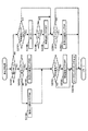
遊技盤2の裏面側には、賞球として払い出される遊技球を溜めておく球タンクの他に、パチンコ遊技機1の動作を制御する制御装置が設けられている。図14に例示されるように、パチンコ遊技機1の制御装置は、判定の実行や演出制御基板130へのコマンド送信処理等を制御する遊技制御基板100、遊技制御基板100から受信したコマンドに基づいて演出を統括的に制御する演出制御基板130、画像や音による演出を制御する画像音響制御基板140、各種のランプやロゴ役物7による演出を制御するランプ制御基板150等から構成されている。本実施形態では、遊技制御基板100が遊技の進行を制御する遊技制御部として機能し、演出制御基板130、画像音響制御基板140、およびランプ制御基板150が演出を制御する演出制御部として機能する。
[Configuration of control device of pachinko gaming machine 1]
On the back side of the game board 2, a control device for controlling the operation of the pachinko gaming machine 1 is provided in addition to a ball tank for storing game balls to be paid out as prize balls. As illustrated in FIG. 14, the control device of the pachinko gaming machine 1 is based on a game control board 100 that controls execution of determination, command transmission processing to the effect control board 130, and commands received from the game control board 100. An effect control board 130 that controls the production in an integrated manner, an image sound control board 140 that controls the production of images and sounds, a lamp control board 150 that controls the production of various lamps and logo accessories 7, and the like. . In the present embodiment, the game control board 100 functions as a game control unit that controls the progress of the game, and the effect control board 130, the image sound control board 140, and the lamp control board 150 function as an effect control unit that controls the effect. .
[遊技制御基板100の構成]
遊技制御基板100は、メインCPU101、メインROM102、およびメインRAM103を備えている。メインCPU101は、メインROM102に記憶されたプログラム等に基づいて、判定や払い出し賞球数に関連する各種の演算処理を行う。メインRAM103は、メインCPU101が上記プログラムを実行する際に用いる各種データを一時的に記憶する記憶領域またはデータ処理などの作業領域として使用される。
[Configuration of Game Control Board 100]
The game control board 100 includes a main CPU 101, a main ROM 102, and a main RAM 103. The main CPU 101 performs various arithmetic processes related to determination and the number of payout balls based on a program stored in the main ROM 102. The main RAM 103 is used as a storage area for temporarily storing various data used when the main CPU 101 executes the program, or a work area for data processing.
遊技制御基板100には、第1始動口スイッチ111、第2始動口スイッチ112、電動チューリップ開閉部113、ゲートスイッチ114、大入賞口スイッチ115、大入賞口制御部116、普通入賞口スイッチ117、特定入賞口スイッチ118、特定領域開閉部119、V入賞口スイッチ120、ハズレ入賞口スイッチ121、V入賞口開閉部122、および表示器4を構成する各表示器41〜43,45〜47が接続されている。
The game control board 100 includes a first start port switch 111, a second start port switch 112, an electric tulip opening / closing unit 113, a gate switch 114, a big winning port switch 115, a big winning port control unit 116, a normal winning port switch 117, The specific prize opening switch 118, the specific area opening / closing part 119, the V prize opening switch 120, the lose prize opening switch 121, the V prize opening opening / closing part 122, and the respective indicators 41 to 43, 45 to 47 constituting the display 4 are connected. Has been.
第1始動口スイッチ111は、第1始動口11に遊技球が入賞したことを検知して、その検知信号を遊技制御基板100に出力する。第2始動口スイッチ112は、第2始動口12に遊技球が入賞したことを検知して、その検知信号を遊技制御基板100に出力する。電動チューリップ開閉部113は、遊技制御基板100からの制御信号に応じて、電動チューリップ17の一対の羽根部材に駆動伝達可能に連結された電動ソレノイドを作動させることによって、第2始動口12を開閉する。ゲートスイッチ114は、遊技球がゲート16を通過したことを検知して、その検知信号を遊技制御基板100に出力する。大入賞口スイッチ115は、大入賞口13に遊技球が入賞したことを検知して、その検知信号を遊技制御基板100に出力する。大入賞口制御部116は、遊技制御基板100からの制御信号に応じて、大入賞口13を閉塞するプレートに駆動伝達可能に連結された電動ソレノイドを作動させることによって、大入賞口13を開閉する。普通入賞口スイッチ117は、遊技球が普通入賞口14に入賞したことを検知して、その検知信号を遊技制御基板100に出力する。
The first start port switch 111 detects that a game ball has won the first start port 11 and outputs a detection signal to the game control board 100. The second start port switch 112 detects that a game ball has won the second start port 12 and outputs a detection signal to the game control board 100. The electric tulip opening / closing part 113 opens and closes the second start port 12 by operating an electric solenoid coupled to the pair of blade members of the electric tulip 17 so as to be able to transmit driving in response to a control signal from the game control board 100. To do. The gate switch 114 detects that the game ball has passed through the gate 16 and outputs the detection signal to the game control board 100. The big prize opening switch 115 detects that a game ball has won the big prize opening 13 and outputs a detection signal to the game control board 100. In response to a control signal from the game control board 100, the special prize opening control unit 116 opens and closes the special prize opening 13 by operating an electric solenoid coupled to a plate that closes the special prize opening 13 so as to be able to transmit the drive. To do. The normal winning port switch 117 detects that the game ball has won the normal winning port 14, and outputs a detection signal to the game control board 100.
特定入賞口スイッチ118は、遊技球が特定入賞口19に入賞したことを検知して、その検知信号を遊技制御基板100に出力する。特定領域開閉部119は、遊技制御基板100からの制御信号に応じて、羽根部材90に駆動伝達可能に連結された電動ソレノイドを作動させることによって、特定入賞口19を開閉する。V入賞口スイッチ120は、遊技球がV入賞口92に入賞したことを検知して、その検知信号を遊技制御基板100に出力する。ハズレ入賞口スイッチ121は、遊技球がハズレ入賞口93に入賞したことを検知して、その検知信号を遊技制御基板100に出力する。V入賞口開閉部122は、遊技制御基板100からの制御信号に応じて、スライド部材94に駆動伝達可能に連結された電動ソレノイドを作動させることによって、V入賞口92を開閉する。
The specific winning opening switch 118 detects that the game ball has won the specific winning opening 19 and outputs a detection signal to the game control board 100. The specific area opening / closing unit 119 opens and closes the specific winning opening 19 by operating an electric solenoid coupled to the blade member 90 so as to be able to transmit driving in response to a control signal from the game control board 100. The V winning opening switch 120 detects that a game ball has won the V winning opening 92 and outputs a detection signal to the game control board 100. The lose prize winning switch 121 detects that the game ball has won the lose prize winning opening 93 and outputs a detection signal to the game control board 100. The V winning opening / closing unit 122 opens and closes the V winning opening 92 by operating an electric solenoid coupled to the slide member 94 so as to be able to transmit driving in response to a control signal from the game control board 100.
遊技制御基板100のメインCPU101は、第1始動口スイッチ111、第2始動口スイッチ112、大入賞口スイッチ115、普通入賞口スイッチ117、V入賞口スイッチ120、またはハズレ入賞口スイッチ121からの検知信号が入力されると、遊技球が入賞した場所に応じた所定数の賞球の払い出しを払出制御基板(不図示)に指示し、払出制御基板からの情報に基づいて、払い出す賞球の個数を管理する。
The main CPU 101 of the game control board 100 detects from the first starting port switch 111, the second starting port switch 112, the big winning port switch 115, the normal winning port switch 117, the V winning port switch 120, or the lose prize port switch 121. When the signal is input, the payout control board (not shown) is instructed to pay out a predetermined number of prize balls according to the place where the game ball has won, and based on the information from the payout control board, Manage the number.
この払出制御基板は、遊技盤2の裏面側に設けられている球タンクから皿28へ賞球を送り出す駆動モータ等を有して構成されている。
This payout control board is configured to have a drive motor or the like that sends out a prize ball from a ball tank provided on the back side of the game board 2 to the tray 28.
メインCPU101は、第1始動口スイッチ111からの検知信号が入力されたタイミングで取得情報としての各種乱数を取得し、取得した乱数を用いて第1特別図柄判定を実行する。また、メインCPU101は、第2始動口スイッチ112からの検知信号が入力されたタイミングで取得情報としての各種乱数を取得し、取得した乱数を用いて第2特別図柄判定を実行する。そして、大当たりであると判定した場合には、大入賞口制御部116を介して大入賞口13を開閉する。
The main CPU 101 acquires various random numbers as acquisition information at the timing when the detection signal from the first start port switch 111 is input, and executes the first special symbol determination using the acquired random numbers. Further, the main CPU 101 acquires various random numbers as acquisition information at the timing when the detection signal from the second start port switch 112 is input, and executes the second special symbol determination using the acquired random numbers. If it is determined that the winning game is a big win, the special winning opening 13 is opened and closed via the special winning opening control unit 116.
また、メインCPU101は、第2特別図柄判定の結果が小当たりであると判定した場合には、特定領域開閉部119を介して羽根部材90を作動させることで特定入賞口19を開閉すると共に、V入賞口開閉部122を介してスライド部材94を作動させることでV入賞口92を開閉する。そして、スライド部材94の作動中にV入賞口92に遊技球が入賞した場合、大当たりであると判定した場合と同様に、大入賞口制御部116を介して大入賞口13を開閉する。
When the main CPU 101 determines that the result of the second special symbol determination is a small hit, the main CPU 101 opens and closes the specific winning opening 19 by operating the blade member 90 via the specific area opening / closing unit 119, The V winning opening 92 is opened and closed by operating the slide member 94 via the V winning opening opening / closing section 122. When the game ball wins the V winning opening 92 during the operation of the slide member 94, the big winning opening 13 is opened and closed via the big winning opening control section 116, as in the case where it is determined that the game is a big win.
また、メインCPU101は、ゲートスイッチ114からの検知信号が入力されたタイミングで乱数を取得し、取得した乱数を用いて普通図柄判定を実行する。そして、第2始動口12を開放すると判定した場合、電動チューリップ開閉部113を介して電動チューリップ17を作動させることによって、第2始動口12を一時的に開放する。
Further, the main CPU 101 acquires a random number at the timing when the detection signal from the gate switch 114 is input, and executes normal symbol determination using the acquired random number. And when it determines with opening the 2nd starting port 12, the 2nd starting port 12 is opened temporarily by operating the electric tulip 17 via the electric tulip opening / closing part 113.
また、メインCPU101は、表示器4を構成する各表示器41〜43および45〜47に対して、図2に基づいて上述した処理を実行させる。
Further, the main CPU 101 causes each of the displays 41 to 43 and 45 to 47 constituting the display 4 to execute the processing described above based on FIG.
[演出制御基板130の構成]
演出制御基板130は、サブCPU131、サブROM132、サブRAM133、およびRTC(リアルタイムクロック)134を備えている。サブCPU131は、サブROM132に記憶されたプログラムに基づいて、演出を制御する際の演算処理を行う。サブRAM133は、サブCPU131が上記プログラムを実行する際に用いる各種データを一時的に記憶する記憶領域またはデータ処理などの作業領域として使用される。
[Configuration of Production Control Board 130]
The effect control board 130 includes a sub CPU 131, a sub ROM 132, a sub RAM 133, and an RTC (real time clock) 134. The sub CPU 131 performs a calculation process when controlling the presentation based on the program stored in the sub ROM 132. The sub RAM 133 is used as a storage area for temporarily storing various data used when the sub CPU 131 executes the program, or a work area for data processing.
RTC134は、現時点の日時を計測する。RTC134は、パチンコ遊技機1に島電源供給装置500からの電力が供給されているときにはこの電力によって動作し、パチンコ遊技機1に島電源供給装置500からの電力が供給されていないときにはパチンコ遊技機1に内蔵されている不図示のバックアップ電源から供給される電力によって動作する。このため、RTC134は、パチンコ遊技機1の電源が投入されていないときにも現在の日時を計測することができる。なお、遊技制御基板100上に電池を設けて、RTC134をこの電池から供給される電力によって動作させるようにしてもよい。
The RTC 134 measures the current date and time. The RTC 134 operates with this power when the power from the island power supply device 500 is supplied to the pachinko gaming machine 1, and when the power from the island power supply device 500 is not supplied to the pachinko gaming machine 1, the RTC 134 operates. 1 operates with electric power supplied from a backup power supply (not shown) built in the apparatus 1. For this reason, the RTC 134 can measure the current date and time even when the power of the pachinko gaming machine 1 is not turned on. Note that a battery may be provided on the game control board 100 and the RTC 134 may be operated by electric power supplied from the battery.
後に詳述するが、画像音響制御基板140の統括CPU141(図15参照)は、RTC134から現在の日付および時刻を示す情報(以下「RTC情報」という。)を取得して、上述した新曲発表演出等を実行する。
As will be described in detail later, the overall CPU 141 (see FIG. 15) of the image sound control board 140 acquires information indicating the current date and time (hereinafter referred to as “RTC information”) from the RTC 134, and the above-described new song presentation effect. Etc.
演出制御基板130のサブCPU131は、遊技制御基板100から送信される特別図柄判定や普通図柄判定、特別遊技等に関する遊技情報に基づいて、通常演出の演出内容を設定する。その際、演出ボタン26または演出キー27からの操作情報の入力を受け付けて、その操作情報に応じた演出内容を設定する場合もある。また、サブCPU131は、設定した演出内容の演出の実行を指示するコマンドを画像音響制御基板140およびランプ制御基板150に送信する。
The sub CPU 131 of the effect control board 130 sets the effect contents of the normal effect based on the game information related to the special symbol determination, the normal symbol determination, the special game, etc. transmitted from the game control board 100. In that case, the input of the operation information from the production | presentation button 26 or the production | presentation key 27 is received, and the production | generation content according to the operation information may be set. Further, the sub CPU 131 transmits a command for instructing execution of the effect of the set effect content to the image sound control board 140 and the lamp control board 150.
[ランプ制御基板150の構成]
ランプ制御基板150は、図には示されていないが、CPU、ROM、およびRAMを備えている。ランプ制御基板150のCPUは、ROMに記憶されたプログラムに基づいて、枠ランプ25やロゴ役物7の動作を制御する際の演算処理を行う。ランプ制御基板150のRAMは、CPUが上記プログラムを実行する際に用いる各種データを一時的に記憶する記憶領域またはデータ処理などの作業領域として使用される。
[Configuration of Lamp Control Board 150]
Although not shown in the drawing, the lamp control board 150 includes a CPU, a ROM, and a RAM. The CPU of the lamp control board 150 performs arithmetic processing when controlling the operation of the frame lamp 25 and the logo accessory 7 based on a program stored in the ROM. The RAM of the lamp control board 150 is used as a storage area for temporarily storing various data used when the CPU executes the program or a work area for data processing.
ランプ制御基板150のROMには、発光パターンデータおよび動作パターンデータが記憶されている。ここで、発光パターンデータは、枠ランプ25やロゴ役物7が備える発光素子のそれぞれの発光パターンを示すデータである。動作パターンデータは、ロゴ役物7の動作パターンを示すデータである。
The ROM of the lamp control board 150 stores light emission pattern data and operation pattern data. Here, the light emission pattern data is data indicating the light emission patterns of the light emitting elements included in the frame lamp 25 and the logo accessory 7. The operation pattern data is data indicating an operation pattern of the logo accessory 7.
ランプ制御基板150のCPUは、ROMに記憶された発光パターンデータの中から、演出制御基板130から受信したコマンドに対応する発光パターンデータをRAM153に読み出して、枠ランプ25やロゴ役物7の発光素子の発光を制御する。また、ランプ制御基板150のCPUは、ROMに記憶された動作パターンデータの中から、演出制御基板130から受信したコマンドに対応する動作パターンデータをRAMに読み出して、ロゴ役物7を動作させるモータの駆動を制御する。
The CPU of the lamp control board 150 reads the light emission pattern data corresponding to the command received from the effect control board 130 from the light emission pattern data stored in the ROM, and emits the light from the frame lamp 25 and the logo accessory 7. Controls the light emission of the device. The CPU of the lamp control board 150 reads out the operation pattern data corresponding to the command received from the effect control board 130 from the operation pattern data stored in the ROM, and operates the logo accessory 7. Control the drive.
[画像音響制御基板140の構成]
図15は、画像音響制御基板140の構成例を示すブロック図である。画像音響制御基板140は、メイン液晶表示装置5およびサブ液晶表示装置6の画像表示制御と、スピーカ24からの音声出力制御とを行うものである。この画像音響制御基板140は、統括CPU141、画像制御部(VDP:Video Display Processor)142、音響DSP(Digital Signal Processor)143、制御用ROM144、制御用RAM145、音響用ROM146、SDRAM147、CGROM148、およびVRAM149を備えている。
[Configuration of Image Sound Control Board 140]
FIG. 15 is a block diagram illustrating a configuration example of the image sound control board 140. The image sound control board 140 performs image display control of the main liquid crystal display device 5 and the sub liquid crystal display device 6 and audio output control from the speaker 24. The image sound control board 140 includes an overall CPU 141, an image control unit (VDP: Video Display Processor) 142, an sound DSP (Digital Signal Processor) 143, a control ROM 144, a control RAM 145, a sound ROM 146, an SDRAM 147, a CGROM 148, and a VRAM 149. It has.
統括CPU141は、制御用ROM144に記憶されているプログラムや各種テーブル、演出制御基板130から受信したコマンド、RTC134から取得したRTC情報に基づいて、VDP142に対して、CGROM148に記憶されている画像データをメイン液晶表示装置5またはサブ液晶表示装置6に表示させる指示を行う。この指示は、主にディスプレイリストの出力によって行われる。
The overall CPU 141 stores the image data stored in the CGROM 148 with respect to the VDP 142 based on the programs and various tables stored in the control ROM 144, the commands received from the effect control board 130, and the RTC information acquired from the RTC 134. An instruction to display on the main liquid crystal display device 5 or the sub liquid crystal display device 6 is given. This instruction is mainly performed by outputting a display list.
ここで、ディスプレイリストは、フレーム単位で描画の実行を指示するためのコマンド群で構成されており、描画する画像の種類、画像を描画する位置(座標)、表示の優先順位、表示倍率、回転角、透過率等の各種パラメータを含むものである。このディスプレイリストを作成する処理については、後に詳述する。
Here, the display list is composed of commands for instructing execution of drawing in frame units. The type of image to be drawn, the position (coordinates) to draw the image, display priority, display magnification, and rotation. It includes various parameters such as angle and transmittance. The processing for creating this display list will be described in detail later.
統括CPU141は、音響DSP143に対しても、音響用ROM146に記憶されている音響データをスピーカ24から出力させる指示を行う。
The overall CPU 141 instructs the sound DSP 143 to output the sound data stored in the sound ROM 146 from the speaker 24.
制御用ROM144は、マスクROMで構成されており、統括CPU141の制御プログラム、ディスプレイリストを生成するためのディスプレイリスト生成プログラム、各種テーブル(図36参照)等が記憶されている。
The control ROM 144 is configured by a mask ROM, and stores a control program for the overall CPU 141, a display list generation program for generating a display list, various tables (see FIG. 36), and the like.
制御用RAM145は、統括CPU141が上記プログラムを実行する際に用いる各種データを一時的に記憶する記憶領域またはデータ処理などの作業領域として使用される。
The control RAM 145 is used as a storage area for temporarily storing various data used when the general CPU 141 executes the program, or a work area for data processing.
CGROM148は、フラッシュメモリ、EEPROM、EPROM、マスクROM等から構成され、所定範囲の画素(例えば32×32ピクセル)における画素情報の集まりからなるスプライトデータ(1枚の画像データ)、複数の画像データの集まりからなるムービーデータ等を圧縮して記憶している。なお、画素情報は、それぞれの画素毎に色番号を指定する色番号情報と画像の透明度を示すα値とから構成されている。また、CGROM148は、色番号を指定する色番号情報と実際に色を表示するための表示色情報とが対応づけられたパレットデータ等を圧縮せずに記憶している。
The CGROM 148 includes a flash memory, an EEPROM, an EPROM, a mask ROM, and the like, and includes sprite data (one piece of image data) including a collection of pixel information in a predetermined range of pixels (for example, 32 × 32 pixels), and a plurality of pieces of image data. Stores compressed movie data and the like. The pixel information is composed of color number information for specifying a color number for each pixel and an α value indicating the transparency of the image. Further, the CGROM 148 stores, without compressing, palette data or the like in which color number information for specifying a color number and display color information for actually displaying colors are associated with each other.
VDP142は、統括CPU141によって作成されたディスプレイリストに基づいてどの新曲の新曲発表演出が行われるかを特定し、特定した新曲の新曲発表演出用ムービーデータCGROM148から読み出して、新曲発表演出を行うための描画処理を実行する。
The VDP 142 identifies which new song new song announcement effect is to be performed based on the display list created by the overall CPU 141, reads out the specified new song from the new song announcement movie data CGROM 148, and performs the new song announcement effect. Perform drawing processing.
また、CGROM148には、通常演出の画像を生成するために使用されるスプライトデータとして、デフォルト演出データおよび特別演出データを記憶している。デフォルト演出データは、新曲発表演出が行われたか否かに関わらず使用可能なデータである。これに対して、特別演出データは、初回の新曲発表演出行われることではじめて使用可能になるスプライトデータであり、それぞれの新曲に対して個別に記憶されている。例えば、特別演出データは、新曲発表演出用ムービーデータを構成する画像データを編集する形で予め生成された演出データや、初回の新曲発表演出が行われることで使用可能となる装飾図柄画像(人物画像)を用いた変動演出を実行するための演出データ等を含んでいる。なお、本実施形態では、初回の新曲発表演出が行われることで使用可能となる装飾図柄画像の人物画像のみが個別に用意されていてもよく、この場合、CGROM148には、当該人物画像を示す画像データ等が記憶される。
Further, the CGROM 148 stores default effect data and special effect data as sprite data used for generating a normal effect image. The default effect data is data that can be used regardless of whether or not a new song announcement effect has been performed. On the other hand, the special effect data is sprite data that can be used only when the first new song announcement effect is performed, and is stored individually for each new song. For example, special effect data may be effect data generated in advance by editing image data constituting movie data for new song announcement effect, or a decorative symbol image (person) that can be used when the first new song announcement effect is performed. Production data for executing a variation production using (image) is included. In the present embodiment, only a person image of a decorative symbol image that can be used when the first new song announcement effect is performed may be individually prepared. In this case, the CGROM 148 indicates the person image. Image data and the like are stored.
なお、新たに使用可能となった特別演出データを用いた通常演出の出現率をできるだけ高くするために、使用可能な特別演出データが増える毎にデフォルト演出データのみを用いた通常演出の出現率を徐々に低下させてもよい。典型的には、デフォルト演出データのみを用いた通常演出の出現率が、最終的にゼロとなるように設定してもよい。この場合、新曲の初回新曲発表演出が行われる毎にディスプレイリスト作成テーブルを切り替える特別選択が実行される。この特別選択については、後に詳述する。
In addition, in order to make the appearance rate of the normal effect using the newly available special effect data as high as possible, the appearance rate of the normal effect using only the default effect data is increased every time the usable special effect data increases. You may make it fall gradually. Typically, the appearance rate of the normal effect using only the default effect data may be set to finally become zero. In this case, a special selection for switching the display list creation table is performed each time the first new song announcement effect of the new song is performed. This special selection will be described in detail later.
VDP142は、統括CPU141によって作成されたディスプレイリストに基づいてデフォルト演出データまたは特別演出データをCGROM148から読み出して、通常演出を行うための描画処理を実行する。初回新曲発表演出が1度も行われていないときには、特別演出データが読み出されることはないため、デフォルト演出データを用いた描画処理が行われて、例えばデフォルトの背景画像がメイン液晶表示装置5に表示される。これに対して、例えば新曲Aの初回新曲発表演出が行われると、新曲Aに対する特別演出データが使用可能となり、当該特別演出データを用いた描画処理が行われる場合、例えば新曲Aに関する背景画像がメイン液晶表示装置5に表示される演出が行われるようになる。一例として、新曲Aを用いた変動演出が行われる場合、新曲Aに関する背景画像(例えば、新曲Aを演奏する動画像)がメイン液晶表示装置5に表示される演出が行われて新曲Aがスピーカ24から音声出力される。このとき、新曲Aに関連する人物画像を固有に用意しておき、新曲Aを用いた変動演出が行われる場合に当該人物画像を含む装飾図柄画像がメイン液晶表示装置5に変動表示されてもよい。このように、本実施形態におけるパチンコ遊技機1では、新曲の初回新曲発表演出を契機として、当該新曲の特別演出データの使用制限が解除されることになる。
The VDP 142 reads out default effect data or special effect data from the CGROM 148 based on the display list created by the overall CPU 141, and executes a drawing process for performing a normal effect. When the first new song announcement effect has never been performed, the special effect data is not read, so that the rendering process using the default effect data is performed. For example, a default background image is displayed on the main liquid crystal display device 5. Is displayed. On the other hand, for example, when the first new song announcement effect of the new song A is performed, the special effect data for the new song A can be used, and when the drawing process using the special effect data is performed, for example, a background image related to the new song A is displayed. An effect displayed on the main liquid crystal display device 5 is performed. As an example, when a variation effect using the new song A is performed, an effect that a background image related to the new song A (for example, a moving image playing the new song A) is displayed on the main liquid crystal display device 5 is performed, and the new song A is a speaker. 24 is output as audio. At this time, a person image related to the new song A is prepared uniquely, and when a variation effect using the new song A is performed, a decorative design image including the person image is displayed on the main liquid crystal display device 5 variably. Good. As described above, in the pachinko gaming machine 1 according to the present embodiment, the use restriction of the special effect data of the new song is released when the first new song announcement effect of the new song is triggered.
なお、CGROM148に記憶される画像データの一部のみを圧縮しておくようにしてもよい。また、ムービーデータの圧縮方法としては、MPEG4等の公知の種々の圧縮方式を用いることができる。
Note that only a part of the image data stored in the CGROM 148 may be compressed. As a method for compressing movie data, various known compression methods such as MPEG4 can be used.
VRAM149は、画像データを高速に書き込んだり読み出したりすることができるSRAMで構成されている。また、VRAM149は、ディスプレイリスト記憶領域1491、メイン液晶用フレームバッファ1495、サブ液晶用フレームバッファ1496を有して構成されている。
The VRAM 149 is an SRAM that can write and read image data at high speed. The VRAM 149 includes a display list storage area 1491, a main liquid crystal frame buffer 1495, and a sub liquid crystal frame buffer 1496.
ディスプレイリスト記憶領域1491は、統括CPU141から出力されたディスプレイリストを一時的に記憶するものである。メイン液晶用フレームバッファ1495は、メイン液晶表示装置5に表示される画像データを一時的に記憶する表示用フレームバッファである。サブ液晶用フレームバッファ1496は、サブ液晶表示装置6に表示される画像データを描画して表示するための描画と表示に兼用されるフレームバッファである。
The display list storage area 1491 temporarily stores the display list output from the overall CPU 141. The main liquid crystal frame buffer 1495 is a display frame buffer that temporarily stores image data displayed on the main liquid crystal display device 5. The sub liquid crystal frame buffer 1496 is a frame buffer used for both drawing and display for drawing and displaying the image data displayed on the sub liquid crystal display device 6.
VDP142は、ディスプレイリスト記憶領域1491に格納されたディスプレイリストに基づいて、メイン液晶用フレームバッファ1495またはサブ液晶用フレームバッファ1496を用いて描画処理を行う。また、VDP142は、VRAM149内の表示用フレームバッファ(メイン液晶用フレームバッファ1495またはサブ液晶用フレームバッファ1496)に記憶された画像データから画像の色を示す映像信号としてのRGB信号を生成し、生成したRGB信号をメイン液晶表示装置5またはサブ液晶表示装置6に出力する。
The VDP 142 performs drawing processing using the main liquid crystal frame buffer 1495 or the sub liquid crystal frame buffer 1496 based on the display list stored in the display list storage area 1491. The VDP 142 generates an RGB signal as a video signal indicating the color of the image from the image data stored in the display frame buffer (the main liquid crystal frame buffer 1495 or the sub liquid crystal frame buffer 1496) in the VRAM 149. The processed RGB signals are output to the main liquid crystal display device 5 or the sub liquid crystal display device 6.
音響DSP143には、楽曲や音声、効果音等に関する各種音響データを記憶する音響用ROM146と、音響DSP143によるデータ処理等の作業領域として使用されるSDRAM147が接続されている。音響DSP143は、統括CPU141からの指示に対応する音響データを音響用ROM146からSDRAM147に読み出してデータ処理を実行し、データ処理後の音響データをスピーカ24に出力させる。
Connected to the acoustic DSP 143 are an acoustic ROM 146 for storing various acoustic data relating to music, voice, sound effects, etc., and an SDRAM 147 used as a work area for data processing by the acoustic DSP 143. The acoustic DSP 143 reads the acoustic data corresponding to the instruction from the overall CPU 141 from the acoustic ROM 146 to the SDRAM 147, executes data processing, and outputs the acoustic data after the data processing to the speaker 24.
[遊技制御基板100によるタイマ割込み処理]
次に、図16を参照しつつ、遊技制御基板100において実行されるタイマ割込み処理について説明する。ここで、図16は、遊技制御基板100において実行されるタイマ割込み処理の一例を示すフローチャートである。遊技制御基板100は、電源投入時や電源断時等の特殊な場合を除く通常の動作時において、図16に例示されている一連の処理を一定時間(例えば4ミリ秒)毎に繰り返し実行する。なお、図16以降のフローチャートに基づいて説明する遊技制御基板100の処理は、メインROM102に記憶されているプログラムに基づいてメインCPU101が発行する命令に従って行われる。
[Timer interrupt processing by game control board 100]
Next, a timer interrupt process executed in the game control board 100 will be described with reference to FIG. Here, FIG. 16 is a flowchart showing an example of timer interrupt processing executed in the game control board 100. The game control board 100 repeatedly executes a series of processes illustrated in FIG. 16 at regular time intervals (for example, 4 milliseconds) during normal operation except for special cases such as when the power is turned on and when the power is turned off. . Note that the processing of the game control board 100 described based on the flowcharts of FIG. 16 and subsequent figures is performed according to a command issued by the main CPU 101 based on a program stored in the main ROM 102.
まず、メインCPU101は、大当たり乱数、大当たり用図柄乱数、小当たり用図柄乱数、リーチ乱数、変動パターン乱数、および普通図柄乱数の各種乱数を更新する乱数更新処理を実行する(ステップ1)。
First, the main CPU 101 executes random number update processing for updating various random numbers of the jackpot random number, the jackpot symbol random number, the jackpot symbol random number, the reach random number, the variation pattern random number, and the normal symbol random number (step 1).
ここで、大当たり乱数は、大当たり、小当たり、またはハズレを決定するための乱数である。大当たり用図柄乱数は、大当たりであると判定された場合に、大当たりの種類を決定するための乱数である。小当たり用図柄乱数は、小当たり遊技中にV入賞口92に遊技球が入賞した場合に発生する2種大当たりの種類を決定するための乱数である。リーチ乱数は、ハズレであると判定された場合に、リーチ有りの演出を行うか或いはリーチ無しの演出を行うかを決定するための乱数である。変動パターン乱数は、特別図柄が変動表示される際の変動パターンを決定するための乱数である。普通図柄乱数は、第2始動口12を開放するか否かを決定するための乱数である。大当たり乱数、大当たり用図柄乱数、小当たり用図柄乱数、リーチ乱数、変動パターン乱数、および普通図柄乱数は、このステップ1の処理が行われる毎に「1」ずつ加算される。なお、このステップ1の処理を行うカウンタとしてはループカウンタが使用されており、各乱数は、予め設定された最大値に達した後は「0」に戻る。
Here, the jackpot random number is a random number for determining the jackpot, the jackpot, or the loss. The jackpot design random number is a random number for determining the type of jackpot when it is determined that the jackpot is a jackpot. The small hitting design random number is a random number for determining the type of two types of big hits generated when a game ball wins the V winning opening 92 during the small hitting game. The reach random number is a random number for determining whether to perform an effect with reach or an effect without reach when it is determined that the reach is lost. The variation pattern random number is a random number for determining a variation pattern when a special symbol is displayed in a variable manner. The normal symbol random number is a random number for determining whether or not to open the second start port 12. The jackpot random number, the jackpot symbol random number, the jackpot symbol random number, the reach random number, the variation pattern random number, and the normal symbol random number are incremented by “1” every time the process of step 1 is performed. Note that a loop counter is used as the counter for performing the processing of step 1, and each random number returns to “0” after reaching a preset maximum value.
ステップ1の処理に続いて、メインCPU101は、各スイッチからの検知信号が入力された場合に、スイッチ処理を実行する(ステップ2)。このスイッチ処理については、図17〜図20に基づいて後に詳述する。
Subsequent to the process in step 1, the main CPU 101 executes a switch process when a detection signal is input from each switch (step 2). This switch process will be described in detail later with reference to FIGS.
ステップ2の処理に続いて、メインCPU101は、特別図柄判定を実行し、第1特別図柄表示器41または第2特別図柄表示器42に特別図柄を変動表示させてから特別図柄判定の結果を示す判定図柄を停止表示させる処理等を含む特別図柄処理を実行する(ステップ3)。この特別図柄処理については、図21に基づいて後に詳述する。
Subsequent to the processing of step 2, the main CPU 101 executes special symbol determination, displays the special symbol on the first special symbol display 41 or the second special symbol display 42, and shows the result of the special symbol determination. Special symbol processing including processing for stopping and displaying the determination symbol is executed (step 3). This special symbol process will be described later in detail with reference to FIG.
ステップ3の処理に続いて、メインCPU101は、普通図柄判定を実行し、普通図柄表示器45に普通図柄を変動表示させてから普通図柄判定の結果を示す普通図柄を停止表示させる処理等を含む普通図柄処理を実行する(ステップ4)。この普通図柄処理については、図24に基づいて後に詳述する。
Subsequent to the process of step 3, the main CPU 101 includes a process of executing normal symbol determination, causing the normal symbol display unit 45 to display the normal symbol in a variable manner, and then stopping and displaying the normal symbol indicating the result of the normal symbol determination. Normal symbol processing is executed (step 4). This normal symbol processing will be described in detail later based on FIG.
ステップ4の処理に続いて、メインCPU101は、普通図柄判定を行った結果、第2始動口12を開放すると判定した場合に、電動チューリップ開閉部113を介して電動チューリップ17を作動させる電動チューリップ処理を実行する(ステップ5)。この電動チューリップ処理については、図25に基づいて後に詳述する。
Following the process of step 4, the main CPU 101 performs the electric tulip process for operating the electric tulip 17 via the electric tulip opening / closing unit 113 when it is determined that the second start port 12 is opened as a result of performing the normal symbol determination. Is executed (step 5). This electric tulip process will be described in detail later based on FIG.
ステップ5の処理に続いて、メインCPU101は、ステップ3の特別図柄処理において小当たりであると判定した場合に、特定領域開閉部119を介して羽根部材90を作動させると共に、V入賞口開閉部122を介してスライド部材94を作動させる特定領域開放制御処理を実行する(ステップ6)。この特定領域開放制御処理については、図26および図27に基づいて後に詳述する。
Subsequent to the process of step 5, when the main CPU 101 determines that it is a small hit in the special symbol process of step 3, the main CPU 101 operates the blade member 90 via the specific area opening / closing unit 119, and the V prize opening opening / closing unit. A specific area opening control process for operating the slide member 94 via 122 is executed (step 6). The specific area release control process will be described later in detail with reference to FIGS.
ステップ6の処理に続いて、メインCPU101は、ステップ3において大当たりであると判定した場合、または小当たり遊技中にV入賞口92に遊技球が入賞した場合に、大入賞口制御部116を制御して大入賞口13を開放する大入賞口開放制御処理を実行する(ステップ7)。この大入賞口開放制御処理については、図28に基づいて後に詳述する。
Subsequent to the processing in step 6, the main CPU 101 controls the big winning opening control unit 116 when it is determined that the big winning is made in step 3, or when a game ball wins the V winning opening 92 during the small hit game. Then, a special winning opening opening control process for opening the special winning opening 13 is executed (step 7). The special winning opening opening control process will be described in detail later based on FIG.
ステップ7の処理に続いて、メインCPU101は、遊技球の入賞に応じた賞球の払い出しを制御する賞球処理を実行する(ステップ8)。
Subsequent to the process in step 7, the main CPU 101 executes a prize ball process for controlling the payout of the prize ball according to the winning of the game ball (step 8).
ステップ8の処理に続いて、メインCPU101は、ステップ8よりも前の処理ステップにおいてメインRAM103にセット(格納)された各種コマンドや演出内容を決定するために必要な情報を演出制御基板130に送信する送信処理を実行する(ステップ9)。このステップ9の処理が実行されることにより、特別図柄判定や特別遊技に関する遊技情報が演出制御基板130に送信されることになる。この遊技情報は、具体的には、後述する変動開始コマンド、図柄確定コマンド、オープニングコマンド、ラウンド開始コマンド、エンディングコマンド等に含まれる情報である。
Subsequent to the process in step 8, the main CPU 101 transmits to the effect control board 130 information necessary for determining various commands and effect contents set (stored) in the main RAM 103 in the process step prior to step 8. The transmission process is executed (step 9). By executing the process of step 9, game information relating to special symbol determination and special games is transmitted to the effect control board 130. Specifically, the game information is information included in a change start command, a symbol determination command, an opening command, a round start command, an ending command, and the like, which will be described later.
[遊技制御基板100によるスイッチ処理]
図17は、図16のステップ2におけるスイッチ処理の詳細フローチャートである。ステップ1の処理に続いて、メインCPU101は、図17に例示されるように、第1始動口スイッチ111からの検知信号の入力の有無を監視して、ステップ1の処理によって適宜更新される各種乱数(大当たり乱数、大当たり用図柄乱数、リーチ乱数、および変動パターン乱数)について、第1始動口スイッチ111からの検知信号が入力された時点の値を取得する第1始動口スイッチ処理を実行する(ステップ21)。この第1始動口スイッチ処理については、図18に基づいて後に詳述する。
[Switch processing by game control board 100]
FIG. 17 is a detailed flowchart of the switch process in step 2 of FIG. Subsequent to the process of step 1, the main CPU 101 monitors the presence or absence of a detection signal input from the first start port switch 111 as illustrated in FIG. For the random numbers (big hit random number, big hit symbol random number, reach random number, and variation pattern random number), a first start port switch process is executed to obtain a value at the time when the detection signal from the first start port switch 111 is input ( Step 21). The first start port switch process will be described in detail later based on FIG.
次に、メインCPU101は、第2始動口スイッチ112からの検知信号の入力の有無を監視して、ステップ1の処理によって適宜更新される各種乱数(大当たり乱数、大当たり用図柄乱数、小当たり用図柄乱数、リーチ乱数、および変動パターン乱数)について、第2始動口スイッチ112からの検知信号が入力された時点の値を取得する第2始動口スイッチ処理を実行する(ステップ22)。この第2始動口スイッチ処理については、図19に基づいて後に詳述する。
Next, the main CPU 101 monitors the presence or absence of a detection signal input from the second start port switch 112, and various random numbers (big hit random number, big hit symbol random number, small bonus symbol updated as appropriate by the processing in step 1). For the random number, the reach random number, and the variation pattern random number), a second start port switch process is performed to acquire a value at the time when the detection signal from the second start port switch 112 is input (step 22). The second start port switch process will be described in detail later based on FIG.
そして、メインCPU101は、ゲートスイッチ114からの検知信号の入力の有無を監視して、ステップ1の処理によって適宜更新される普通図柄乱数について、ゲートスイッチ114からの検知信号が入力された時点の値を取得するゲートスイッチ処理を実行する(ステップ23)。このゲートスイッチ処理については、図20に基づいて後に詳述する。
The main CPU 101 monitors the presence or absence of the detection signal input from the gate switch 114, and the value at the time when the detection signal from the gate switch 114 is input with respect to the normal symbol random number updated as appropriate in the process of step 1. The gate switch process for acquiring the above is executed (step 23). This gate switch processing will be described in detail later based on FIG.
[遊技制御基板100による第1始動口スイッチ処理]
図18は、図17のステップ21における第1始動口スイッチ処理の詳細フローチャートである。図18に例示されるように、メインCPU101は、ステップ1の乱数更新処理に続いて、第1始動口スイッチ111からの検知信号(第1始動口スイッチ111が「ON」になったことを示すON信号)が入力されたか否かに基づいて、第1始動口スイッチ111が「ON」になったか否かを判定する(ステップ211)。そして、第1始動口スイッチ111が「ON」になったと判定した場合(ステップ211:YES)、メインRAM103に記憶されている第1特別図柄判定の保留数U1が、予めメインROM102に記憶されている第1特別図柄判定の最大保留数Umax1(本実施形態では「4」)未満であるか否かを判定する(ステップ212)。
[First Start Port Switch Processing by Game Control Board 100]
FIG. 18 is a detailed flowchart of the first start port switch process in step 21 of FIG. As illustrated in FIG. 18, following the random number update process in step 1, the main CPU 101 indicates a detection signal from the first start port switch 111 (indicating that the first start port switch 111 is “ON”). Based on whether or not an ON signal is input, it is determined whether or not the first start port switch 111 is turned “ON” (step 211). Then, when it is determined that the first start port switch 111 is “ON” (step 211: YES), the hold number U1 of the first special symbol determination stored in the main RAM 103 is stored in the main ROM 102 in advance. It is determined whether it is less than the maximum reserved number Umax1 (in the present embodiment, “4”) of the first special symbol determination (step 212).
メインCPU101は、保留数U1が最大保留数Umax1未満であると判定した場合(ステップ212:YES)、保留数U1の値を「1」加算した値に更新する(ステップ213)。そして、第1特別図柄判定に使用する取得情報として、大当たり乱数、大当たり用図柄乱数、リーチ乱数、および変動パターン乱数を取得し、これらの乱数を対応付けてメインRAM103の所定領域に格納する(ステップ214〜ステップ217)。
When the main CPU 101 determines that the hold number U1 is less than the maximum hold number Umax1 (step 212: YES), the main CPU 101 updates the value of the hold number U1 to a value obtained by adding “1” (step 213). Then, as the acquisition information used for the first special symbol determination, a jackpot random number, a jackpot symbol random number, a reach random number, and a variation pattern random number are acquired, and these random numbers are associated with each other and stored in a predetermined area of the main RAM 103 (step). 214-step 217).
なお、本実施形態におけるパチンコ遊技機1は、第1特別図柄判定の結果が大当たりまたはハズレのいずれかとなり、第1特別図柄判定においては、小当たり遊技を発生させる小当たりと判定されないように構成されている。このため、第1始動口スイッチ処理には、2種大当たりの種類を決定するための小当たり用図柄乱数を取得するステップが含まれていない。
The pachinko gaming machine 1 in the present embodiment is configured such that the result of the first special symbol determination is either a big hit or a loss, and the first special symbol determination is not determined to be a small hit that generates a small hit game. Has been. For this reason, the first start port switch process does not include a step of acquiring a small hitting design random number for determining the type of the two big hits.
[遊技制御基板100による第2始動口スイッチ処理]
図19は、図17のステップ22における第2始動口スイッチ処理の詳細フローチャートである。図19に示されるように、メインCPU101は、ステップ21の第1始動口スイッチ処理に続いて、第2始動口スイッチ112からの検知信号(第2始動口スイッチ112が「ON」になったことを示すON信号)が入力されたか否かに基づいて、第2始動口スイッチ112が「ON」になったか否かを判定する(ステップ221)。
[Second Start Port Switch Processing by Game Control Board 100]
FIG. 19 is a detailed flowchart of the second start port switch process in step 22 of FIG. As shown in FIG. 19, the main CPU 101 detects the detection signal from the second start port switch 112 (the second start port switch 112 has been turned “ON” following the first start port switch process of step 21. On the basis of whether or not an ON signal indicating that the second start port switch 112 has been turned ON is determined (step 221).
メインCPU101は、第2始動口スイッチ112が「ON」になったと判定した場合(ステップ221:YES)、例えば、メインRAM103に記憶されている長当たり遊技フラグ、短当たり遊技フラグ、または小当たり遊技フラグが「ON」に設定されているか否かに基づいて、特別遊技中であるか否かを判定する(ステップ222)。
When the main CPU 101 determines that the second start port switch 112 is “ON” (step 221: YES), for example, a long hit game flag, a short hit game flag, or a small hit game stored in the main RAM 103. Based on whether the flag is set to “ON”, it is determined whether or not a special game is being played (step 222).
ここで、長当たり遊技フラグは、大入賞口13を長開放する複数の長開放ラウンド遊技からなる長当たり遊技の実行中であるか否かを示すフラグであり、長当たり遊技の開始時に「ON」に設定され、長当たり遊技の終了時に「OFF」に設定される。短当たり遊技フラグは、大入賞口13を短開放する複数の短開放ラウンド遊技からなる短当たり遊技の実行中であるか否かを示すフラグであり、短当たり遊技の開始時に「ON」に設定され、短当たり遊技の終了時に「OFF」に設定される。小当たり遊技フラグは、特定入賞口19を開放する小当たり遊技の実行中であるか否かを示すフラグであり、小当たり遊技の開始時に「ON」に設定され、小当たり遊技の終了時に「OFF」に設定される。
Here, the long win game flag is a flag indicating whether or not a long win game consisting of a plurality of long open round games that open the big winning opening 13 is long, and is set to “ON” at the start of the long win game. Is set to “OFF” at the end of the long hit game. The short win game flag is a flag indicating whether or not a short win game consisting of a plurality of short open round games that open the big winning opening 13 is short, and is set to “ON” at the start of the short win game. And set to “OFF” at the end of the short hit game. The small hit game flag is a flag indicating whether or not a small hit game for opening the specific winning opening 19 is being executed, and is set to “ON” at the start of the small hit game, and “ OFF "is set.
メインCPU101は、特別遊技中ではないと判定した場合(ステップ222:NO)、第1特別図柄表示器41または第2特別図柄表示器42における特別図柄の変動表示中であるか否かを判定する(ステップ223)。ここで、特別図柄の変動表示中ではないと判定した場合(ステップ223:NO)、第2特別図柄判定に使用する取得情報として、大当たり乱数、大当たり用図柄乱数、小当たり用図柄乱数、リーチ乱数、および変動パターン乱数を取得し、これらの乱数を対応付けてメインRAM103の所定領域に格納する(ステップ224〜S228)。
When the main CPU 101 determines that the special game is not being played (step 222: NO), the main CPU 101 determines whether or not the special symbol display on the first special symbol display 41 or the second special symbol display 42 is being displayed. (Step 223). Here, when it is determined that the special symbol variation display is not being performed (step 223: NO), as the acquisition information used for the second special symbol determination, the jackpot random number, the jackpot symbol random number, the jackpot symbol random number, the reach random number , And fluctuation pattern random numbers are acquired, and these random numbers are associated and stored in a predetermined area of the main RAM 103 (steps 224 to S228).
このように、特別遊技中ではなく特別図柄の変動表示中でもないときに第2始動口12に遊技球が入賞した場合には、メインCPU101は、第2特別図柄判定に使用する各種乱数を、メインRAM103の判定用記憶領域に直接格納する。この判定用記憶領域は、特別図柄判定が実際に実行されるときにその特別図柄判定に使用される各種乱数が記憶される記憶領域である。なお、第1始動口11に遊技球が入賞した場合には、メインCPU101は、第1特別図柄判定に使用する各種乱数をメインRAM103の保留記憶領域に格納し、実際に第1特別図柄判定を行って特別図柄の変動表示を開始させるときに、保留記憶領域に記憶されている各種乱数を判定用記憶領域にシフトさせる。
As described above, when the game ball wins the second starting port 12 when the special game is not being displayed and the special symbol is not being displayed, the main CPU 101 stores various random numbers used for the second special symbol determination in the main game. The data is directly stored in the determination storage area of the RAM 103. This determination storage area is a storage area for storing various random numbers used for the special symbol determination when the special symbol determination is actually executed. When a game ball is won at the first starting port 11, the main CPU 101 stores various random numbers used for the first special symbol determination in the reserved storage area of the main RAM 103, and actually performs the first special symbol determination. When the change display of the special symbol is started, various random numbers stored in the reserved storage area are shifted to the determination storage area.
以上説明したように、本実施形態では、特別図柄の変動表示中や特別遊技中に第2始動口12に遊技球が入賞したためにその入賞に対応する第2特別図柄判定に係る特別図柄の変動表示を直ちに開始できない場合には、第2始動口12への遊技球の入賞に基づく第2特別図柄判定は行われない。一方、第1始動口11に遊技球が入賞したときにその入賞に対応する第1特別図柄判定に係る特別図柄の変動表示を直ちに開始できない場合であっても、第1特別図柄判定の権利は、4つを上限として保留される。
As described above, in the present embodiment, since the game ball has won the second starting port 12 during the special symbol change display or during the special game, the special symbol change related to the second special symbol determination corresponding to the winning is made. When the display cannot be started immediately, the second special symbol determination based on the winning of the game ball to the second start port 12 is not performed. On the other hand, when a game ball wins at the first start port 11, even if the variable symbol display related to the first special symbol determination corresponding to the winning cannot be started immediately, the right of the first special symbol determination is 4 is the upper limit.
[遊技制御基板100によるゲートスイッチ処理]
図20は、図17のステップ23におけるゲートスイッチ処理の詳細フローチャートである。図20に示されるように、メインCPU101は、ステップ22の第2始動口スイッチ処理に続いて、ゲートスイッチ114からの検知信号(ゲートスイッチ114が「ON」になったことを示すON信号)が入力されたか否かに基づいて、ゲートスイッチ114が「ON」になったか否かを判定する(ステップ231)。
[Gate switch processing by game control board 100]
FIG. 20 is a detailed flowchart of the gate switch process in step 23 of FIG. As shown in FIG. 20, the main CPU 101 receives a detection signal from the gate switch 114 (ON signal indicating that the gate switch 114 is turned “ON”) following the second start-up switch processing in step 22. It is determined whether or not the gate switch 114 is turned “ON” based on whether or not it is input (step 231).
メインCPU101は、ゲートスイッチ114が「ON」になったと判定した場合(ステップ231:YES)、メインRAM103に記憶されている普通図柄判定の保留数Tが、メインROM102に予め記憶されている普通図柄判定の最大保留数Tmax(例えば「4」)未満であるか否かを判定する(ステップ232)。
When the main CPU 101 determines that the gate switch 114 is turned “ON” (step 231: YES), the normal symbol determination suspension number T stored in the main RAM 103 is stored in the main ROM 102 in advance. It is determined whether or not the determination is less than the maximum hold number Tmax (for example, “4”) (step 232).
メインCPU101は、保留数Tが最大保留数Tmax未満であると判定した場合(ステップ232:YES)、保留数Tを「1」加算した値に更新し(ステップ233)、この処理によって保留された普通図柄判定に使用される普通図柄乱数を取得して、メインRAM103に格納する(ステップ234)。
When the main CPU 101 determines that the hold number T is less than the maximum hold number Tmax (step 232: YES), the main CPU 101 updates the hold number T to a value obtained by adding “1” (step 233) and is held by this process. A normal symbol random number used for normal symbol determination is acquired and stored in the main RAM 103 (step 234).
[遊技制御基板100による特別図柄処理]
次に、図21を参照しつつ、遊技制御基板100によって実行される特別図柄処理の詳細について説明する。ここで、図21は、図16のステップ3における特別図柄処理の詳細フローチャートである。図21に示されるように、遊技制御基板100のメインCPU101は、メインRAM103に記憶されている長当たり遊技フラグ、短当たり遊技フラグ、または小当たり遊技フラグが「ON」に設定されているか否かに基づいて、特別遊技中であるか否かを判定する(ステップ301)。ここで、特別遊技中であると判定された場合(ステップ301:YES)、ステップ4の普通図柄処理に処理が進められる。
[Special symbol processing by game control board 100]
Next, the details of the special symbol process executed by the game control board 100 will be described with reference to FIG. Here, FIG. 21 is a detailed flowchart of the special symbol process in step 3 of FIG. As shown in FIG. 21, the main CPU 101 of the game control board 100 determines whether or not the long hit game flag, short hit game flag, or small hit game flag stored in the main RAM 103 is set to “ON”. Based on the above, it is determined whether or not a special game is in progress (step 301). Here, when it is determined that the special game is being played (step 301: YES), the process proceeds to the normal symbol process of step 4.
メインCPU101は、特別遊技中ではないと判定した場合(ステップ301:NO)、特別図柄の変動表示中であるか否かを判定する(ステップ302)。ここで、特別図柄の変動表示中であると判定された場合(ステップ302:YES)、後述するステップ315に処理が進められる。
When the main CPU 101 determines that the special game is not being played (step 301: NO), the main CPU 101 determines whether or not the special symbol is being changed (step 302). Here, when it is determined that the special symbol variation display is being performed (step 302: YES), the process proceeds to step 315 described later.
メインCPU101は、特別図柄の変動表示中ではないと判定した場合(ステップ302:NO)、第2始動口入賞に係る各種乱数がメインRAM103の判定用記憶領域に記憶されているか否かを判定する(ステップ303)。具体的には、遊技球が第2始動口12に入賞したことに応じて取得された各種乱数が判定用記憶領域に直接記憶されると共に、第2始動口入賞に係る各種乱数が記憶されたことを示すフラグが判定用記憶領域に記憶されるので、判定用記憶領域に各種乱数が記憶された際にこのフラグが記憶されているか否かに基づいて、判定用記憶領域に記憶された各種乱数が第2始動口入賞に係るものであるか或いは第1始動口入賞に係るものであるかを判別する。ここで、第2始動口入賞に係る乱数が記憶されていると判定された場合(ステップ303:YES)、後述するステップ307に処理が進められる。
If the main CPU 101 determines that the special symbol variation display is not in progress (step 302: NO), the main CPU 101 determines whether or not various random numbers related to the second start opening winning are stored in the determination storage area of the main RAM 103. (Step 303). Specifically, various random numbers acquired in response to the game ball winning the second start opening 12 are directly stored in the determination storage area, and various random numbers related to the second start opening winning are stored. Is stored in the determination storage area. Based on whether or not this flag is stored when various random numbers are stored in the determination storage area, various types of information stored in the determination storage area are stored. It is determined whether the random number is related to the second start opening winning or the first starting opening winning. Here, when it is determined that the random number related to the second start opening winning is stored (step 303: YES), the process proceeds to step 307 described later.
メインCPU101は、第2始動口入賞に係る乱数が判定用記憶領域に記憶されていないと判定した場合(ステップ303:NO)、メインRAM103に記憶されている第1特別図柄判定の保留数U1が「1」以上であるか否かを判定する(ステップ304)。ここで、保留数U1が「1」以上ではないと判定された場合(ステップ304:NO)、すなわち第1特別図柄判定の権利が保留されていない場合、後述するステップ321に処理が進められる。
When the main CPU 101 determines that the random number related to the second start opening winning is not stored in the determination storage area (step 303: NO), the main CPU 103 stores the first special symbol determination hold number U1. It is determined whether or not “1” or more (step 304). Here, when it is determined that the number of holds U1 is not equal to or greater than “1” (step 304: NO), that is, when the right of the first special symbol determination is not held, the process proceeds to step 321 described later.
メインCPU101は、保留数U1が「1」以上であると判定した場合(ステップ304:YES)、保留数U1を「1」減算した値に更新する(ステップ305)。そして、メインRAM103の記憶領域に対するシフト処理を実行する(ステップ306)。具体的には、メインRAM103の保留記憶領域に記憶されている第1特別図柄判定に係る大当たり乱数、大当たり用図柄乱数、リーチ乱数、および変動パターン乱数について、保留記憶領域に最初に格納されたもの(最も古いもの)を判定用記憶領域にシフトさせ、残りのものを判定用記憶領域側にシフトさせる。
When the main CPU 101 determines that the hold number U1 is “1” or more (step 304: YES), the main CPU 101 updates the hold number U1 to a value obtained by subtracting “1” (step 305). Then, a shift process for the storage area of the main RAM 103 is executed (step 306). Specifically, the jackpot random number, jackpot symbol random number, reach random number, and variation pattern random number related to the first special symbol determination stored in the reserved storage area of the main RAM 103 are first stored in the reserved storage area. (The oldest) is shifted to the determination storage area, and the remaining one is shifted to the determination storage area.
メインCPU101は、ステップ306の処理を実行した場合、または第2始動口入賞に係る乱数が判定用記憶領域に記憶されていると判定した場合(ステップ303:YES)、判定用記憶領域に記憶されている乱数に基づいて、大当たり判定処理を実行する(ステップ307)。この大当たり判定処理が実行されることによって、大当たり、小当たり、およびハズレのいずれであるかが判定され、その判定結果を示す判定図柄の設定情報がメインRAM103にセットされる。そして、大当たり(1種大当たり)であると判定された場合には大当たりの種類が決定され、小当たりであると判定された場合には小当たり遊技中にV入賞口92に遊技球が入賞したことを契機として発生する2種大当たりの種類が決定される。この大当たり判定処理については、図22に基づいて後に詳述する。
When the main CPU 101 executes the process of step 306 or determines that the random number related to the second start opening winning is stored in the determination storage area (step 303: YES), it is stored in the determination storage area. The jackpot determination process is executed on the basis of the random number (step 307). By executing the jackpot determination process, it is determined whether the jackpot, the small hit, or the loss, and setting information of a determination symbol indicating the determination result is set in the main RAM 103. When it is determined that the game is a big hit (1 type big win), the type of the big win is determined, and when it is determined that the jackpot is a game, the game ball wins the V winning opening 92 during the small hit game. The kind of two types of jackpots that will be triggered by this is determined. The jackpot determination process will be described in detail later based on FIG.
ステップ307の処理に続いて、メインCPU101は、変動パターン選択処理を実行する(ステップ308)。具体的には、メインROM102に予め記憶されている変動パターンテーブルを参照して、ステップ307における大当たり判定の判定結果、メインRAM103にセットされた判定図柄の種類、現在の遊技状態、第1特別図柄判定の保留数U1、上記ステップ307の処理で使用した大当たり乱数と一緒に判定用記憶領域に記憶されているリーチ乱数および変動パターン乱数に基づいて、特別図柄の変動パターンを選択する。このステップ308の処理が行われることによって、リーチ有り演出を行うか、或いはリーチ無し演出を行うかも併せて決定される。
Following the processing in step 307, the main CPU 101 executes variation pattern selection processing (step 308). Specifically, referring to the variation pattern table stored in advance in the main ROM 102, the determination result of the jackpot determination in step 307, the type of determination symbol set in the main RAM 103, the current gaming state, the first special symbol A variation pattern of a special symbol is selected based on the reach random number U1 and the reach random number and variation pattern random number stored in the determination storage area together with the jackpot random number used in the processing of step 307. By performing the processing in step 308, it is also determined whether to perform an effect with reach or an effect without reach.
ステップ308の処理に続いて、メインCPU101は、ステップ307の処理で設定した図柄の設定情報、この図柄の設定情報が第1特別図柄判定に係るものであるか或いは第2特別図柄判定に係るものであるかを示す情報、ステップ308の処理で設定した変動パターンの設定情報、リーチ有り演出とリーチ無し演出のどちらの演出を行うかを示す情報、パチンコ遊技機1の遊技状態に関する情報等を含む変動開始コマンドをメインRAM103にセットする(ステップ309)。この変動開始コマンドは、特別図柄の変動表示に伴う演出の実行を指示するコマンドであって、ステップ9の送信処理によって演出制御基板130に送信される。
Subsequent to step 308, the main CPU 101 determines whether the symbol setting information set in step 307, the symbol setting information relates to the first special symbol determination, or the second special symbol determination. Information indicating whether or not a variation pattern set in the process of step 308, information indicating whether to perform a presence effect or a non-reach effect, information relating to the gaming state of the pachinko gaming machine 1, and the like. A change start command is set in the main RAM 103 (step 309). This variation start command is a command for instructing the execution of the effect accompanying the variation display of the special symbol, and is transmitted to the effect control board 130 by the transmission process of step 9.
これに対して、演出制御基板130は、遊技制御基板100から受信した変動開始コマンドを解析することによって、特別図柄判定の結果を特定し、リーチ有り演出とリーチ無し演出のどちらを行う必要があるのかを判定し、特別図柄が変動表示される変動時間を取得し、パチンコ遊技機1の遊技状態を特定する。そして、第1特別図柄表示器41または第2特別図柄表示器42における特別図柄の変動表示に伴って、メイン液晶表示装置5にどのような演出画像を表示するか、スピーカ24からどのような音を出力するか、枠ランプ25をどのような発光パターンで発光させるか、ロゴ役物7を作動させるか否か等を決定し、決定した内容の演出を画像音響制御基板140およびランプ制御基板150に実行させる。
On the other hand, the effect control board 130 needs to specify the result of the special symbol determination by analyzing the variation start command received from the game control board 100, and perform either the effect with reach or the effect without reach. To determine the game state of the pachinko gaming machine 1 by acquiring the variation time during which the special symbol is variably displayed. Then, accompanying the special symbol variation display on the first special symbol display 41 or the second special symbol display 42, what effect image is displayed on the main liquid crystal display device 5, what kind of sound is output from the speaker 24. Is output, the light emission pattern of the frame lamp 25 is determined, the logo accessory 7 is activated or the like, and the effects of the determined contents are displayed as the image sound control board 140 and the lamp control board 150. To run.
ステップ309の処理に続いて、メインCPU101は、ステップ309の処理でセットした変動開始コマンドに含まれている設定情報に基づいて、特別図柄の変動表示を開始する(ステップ310)。
Subsequent to the processing in step 309, the main CPU 101 starts the special symbol variation display based on the setting information included in the variation start command set in step 309 (step 310).
なお、ステップ310における特別図柄の変動表示は、判定用記憶領域に第1特別図柄判定に係る乱数が記憶されている状態でステップ307およびステップ308の処理が行われた場合には第1特別図柄表示器41を用いて行われ、第2特別図柄判定に係る乱数が記憶されている状態でステップ307およびステップ308の処理が行われた場合には第2特別図柄表示器42を用いて行われる。
Note that the special symbol variation display in step 310 is the first special symbol when the processing in step 307 and step 308 is performed in a state where the random number related to the first special symbol determination is stored in the determination storage area. When the processing of step 307 and step 308 is performed in a state where the random number related to the second special symbol determination is stored, it is performed using the second special symbol display 42. .
ステップ310に続いて、メインCPU101は、メインRAM103に記憶されている客待ちフラグが「ON」に設定されているか否かを判定する(ステップ311)。ここで、客待ちフラグは、パチンコ遊技機1が客待ち状態であるか否かを示すフラグであり、第1特別図柄判定の権利が保留されておらずかつ第1特別図柄判定または第2特別図柄判定に係る特別図柄の変動表示が行われなくなったタイミングで「ON」に設定され、特別図柄の変動表示が再び開始されることで「OFF」に設定される。
Following step 310, the main CPU 101 determines whether or not the customer waiting flag stored in the main RAM 103 is set to “ON” (step 311). Here, the customer waiting flag is a flag indicating whether or not the pachinko gaming machine 1 is in a customer waiting state, the right of the first special symbol determination is not reserved, and the first special symbol determination or the second special symbol is not held. It is set to “ON” at the timing when the special symbol variation display related to symbol determination is not performed, and is set to “OFF” when the special symbol variation display is started again.
メインCPU101は、客待ちフラグが「ON」に設定されていると判定した場合(ステップ311:YES)、客待ちフラグを「OFF」に設定する(ステップ312)。一方、客待ちフラグが「ON」に設定されていないと判定された場合(ステップ311:NO)、ステップ313に処理が進められる。
When determining that the customer waiting flag is set to “ON” (step 311: YES), the main CPU 101 sets the customer waiting flag to “OFF” (step 312). On the other hand, if it is determined that the customer waiting flag is not set to “ON” (step 311: NO), the process proceeds to step 313.
メインCPU101は、ステップ312の処理を実行した場合、または客待ちフラグが「ON」に設定されていないと判定した場合(ステップ311:NO)、変動時間の計測を開始する(ステップ313)
When the main CPU 101 executes the process of step 312 or determines that the customer waiting flag is not set to “ON” (step 311: NO), the main CPU 101 starts measuring the variation time (step 313).
メインCPU101は、ステップ313の処理を実行した場合、または特別図柄の変動表示中であると判定した場合(ステップ302:YES)、ステップ313における変動時間の計測開始から、ステップ308の処理によって選択された変動パターンに対応する変動時間が経過したか否かを判定する(ステップ315)。ここで、変動時間が経過していないと判定された場合(ステップ315:NO)、一連の特別図柄処理が終了してステップ4の普通図柄に処理が進められる。
When the main CPU 101 executes the process of step 313 or determines that the special symbol is changing (step 302: YES), the main CPU 101 is selected by the process of step 308 from the start of the measurement of the changing time in step 313. It is determined whether or not the variation time corresponding to the variation pattern has elapsed (step 315). Here, when it is determined that the variation time has not elapsed (step 315: NO), a series of special symbol processing ends and the processing proceeds to the normal symbol of step 4.
メインCPU101は、変動時間が経過したと判定した場合(ステップ315:YES)、第1特別図柄表示器41または第2特別図柄表示器42に特別図柄判定の判定結果を示す判定図柄が停止表示されることを通知する図柄確定コマンドをメインRAM103にセットする(ステップ316)。この図柄確定コマンドは、ステップ9における送信処理によって演出制御基板130に送信される。これにより、メイン液晶表示装置5に変動表示されていた装飾図柄を特別図柄判定の判定結果を示す態様で停止表示させる処理等が行われることになる。
When the main CPU 101 determines that the variation time has elapsed (step 315: YES), the determination symbol indicating the determination result of the special symbol determination is stopped and displayed on the first special symbol display 41 or the second special symbol display 42. Is set in the main RAM 103 (step 316). This symbol confirmation command is transmitted to the effect control board 130 by the transmission process in step 9. Thereby, the process etc. which stop-display the decoration symbol which was variably displayed on the main liquid crystal display device 5 in the aspect which shows the determination result of special symbol determination, etc. are performed.
ステップ316の処理に続いて、メインCPU101は、ステップ310の処理で開始した特別図柄の変動表示を終了する(ステップ317)。その際、ステップ307の処理で設定した判定図柄(大当たり図柄、小当たり図柄、またはハズレ図柄)を、特別図柄を変動表示していた特別図柄表示器に停止表示させる(ステップ314)。すなわち、第1特別図柄表示器41に大当たり図柄またはハズレ図柄を停止表示させ、第2特別図柄表示器42に大当たり図柄、小当たり図柄、またはハズレ図柄を停止表示させる。
Subsequent to the process in step 316, the main CPU 101 ends the special symbol variation display started in the process in step 310 (step 317). At this time, the determination symbol set in the process of step 307 (big hit symbol, small hit symbol, or lost symbol) is stopped and displayed on the special symbol display that has variably displayed the special symbol (step 314). That is, the first special symbol display unit 41 stops and displays the big hit symbol or the lost symbol, and the second special symbol display unit 42 stops and displays the big hit symbol, the small hit symbol, or the lost symbol.
ステップ318の処理に続いて、メインCPU101は、上記ステップ313の処理で計測を開始した変動時間をリセットし(ステップ318)、大当たりである場合に第1特別遊技を開始させ、小当たりである場合に小当たり遊技を開始させる処理等を含む停止中処理を実行する(ステップ319)。この停止中処理については、図23に基づいて後に詳述する。
Subsequent to the process of step 318, the main CPU 101 resets the variation time that started the measurement in the process of step 313 (step 318), starts the first special game if it is a big win, and if it is a small win A process during stop including a process for starting a small hit game is executed (step 319). This stop process will be described later in detail with reference to FIG.
一方、メインCPU101は、第1特別図柄判定の保留数U1が「1」以上ではないと判定した場合(ステップ304:NO)、客待ちフラグが「ON」に設定されているか否かを判定する(ステップ321)。ここで、客待ちフラグが「ON」に設定されていると判定された場合(ステップ321:YES)、ステップ4の普通図柄に処理が進められる。
On the other hand, if the main CPU 101 determines that the number U1 of the first special symbol determination is not “1” or more (step 304: NO), the main CPU 101 determines whether or not the customer waiting flag is set to “ON”. (Step 321). If it is determined that the customer waiting flag is set to “ON” (step 321: YES), the process proceeds to the normal symbol in step 4.
メインCPU101は、客待ちフラグが「ON」に設定されていないと判定した場合(ステップ321:YES)、パチンコ遊技機1が客待ち状態になったことを通知する客待ちコマンドをメインRAM103にセットし(ステップ322)、客待ちフラグを「ON」に設定する(ステップ323)。この客待ちコマンドは、ステップ9の送信処理によって演出制御基板130に送信される。その結果、客待ちコマンドが送信されてから所定時間(本実施形態では30秒)が経過すると、客待ち演出が開始される。
When the main CPU 101 determines that the customer waiting flag is not set to “ON” (step 321: YES), the main CPU 101 sets a customer waiting command for notifying that the pachinko gaming machine 1 is in the customer waiting state in the main RAM 103. (Step 322), the customer waiting flag is set to "ON" (Step 323). This customer waiting command is transmitted to the effect control board 130 by the transmission process of step 9. As a result, when a predetermined time (in this embodiment, 30 seconds) elapses after the customer waiting command is transmitted, the customer waiting effect is started.
[遊技制御基板100による大当たり判定処理]
図22は、図21のステップ307における大当たり判定処理の詳細フローチャートである。メインCPU101は、メインRAM103の判定用記憶領域に第2特別図柄判定に係る乱数が記憶されていると判定した場合(ステップ303:YES)、またはステップ306の処理を実行した場合、図22に示されるように、大当たり判定を実行する(ステップ3071)。ここで、メインCPU101は、第2始動口入賞に係る大当たり判定を実行する場合にはメインROM102に予め記憶されている第2始動口入賞用大当たり判定テーブルを参照し、第1始動口入賞に係る大当たり判定を実行する場合にはメインROM102に予め記憶されている第1始動口入賞用大当たり判定テーブルを参照する。
[Big hit judgment processing by game control board 100]
FIG. 22 is a detailed flowchart of the jackpot determination process in step 307 of FIG. When the main CPU 101 determines that a random number related to the second special symbol determination is stored in the determination storage area of the main RAM 103 (step 303: YES), or when the process of step 306 is executed, the process shown in FIG. The jackpot determination is executed as described above (step 3071). Here, when the main CPU 101 executes the jackpot determination related to the second starting port winning, the main CPU 101 refers to the second starting port winning jackpot determination table stored in advance in the main ROM 102 and relates to the first starting port winning. When the jackpot determination is executed, the first start opening winning jackpot determination table stored in the main ROM 102 is referred to.
第2始動口入賞用大当たり判定テーブルには、判定結果と乱数値とが対応付けられて記憶されている。具体的には、大当たりに対する乱数値と、小当たりに対する乱数値と、ハズレに対する乱数値とが記憶されている。メインCPU101は、第2始動口入賞に係る大当たり判定を実行する場合、判定用記憶領域に記憶されている大当たり乱数が、第2始動口入賞用大当たり判定テーブルに規定されているどの乱数値と一致するかに基づいて、大当たり(1種大当たり)であるか、小当たりであるか、またはハズレであるかを判定する。
In the second start opening winning jackpot determination table, a determination result and a random value are stored in association with each other. Specifically, a random value for the big hit, a random value for the small hit, and a random value for the loss are stored. When the main CPU 101 executes the jackpot determination related to the second start opening winning a prize, the jackpot random number stored in the determination storage area matches any random value defined in the second starting opening winning jackpot determination table It is determined whether it is a big hit (one type big hit), a small hit or a loss based on whether or not.
第1始動口入賞用大当たり判定テーブルには、判定結果と乱数値とが対応付けられて記憶されている。具体的には、大当たりに対する乱数値とハズレに対する乱数値とが記憶されている。メインCPU101は、第1始動口入賞に係る大当たり判定を実行する場合、判定用記憶領域に記憶されている大当たり乱数が、第1始動口入賞用大当たり判定テーブルに規定されているどの乱数値と一致するかに基づいて、大当たり(1種大当たり)であるか、またはハズレであるかを判定する。
In the first start opening winning jackpot determination table, a determination result and a random value are stored in association with each other. Specifically, a random value for jackpot and a random value for loss are stored. When the main CPU 101 executes the jackpot determination related to the first start opening winning prize, the jackpot random number stored in the determination storage area matches any random number value defined in the first starting opening winning jackpot determination table It is determined whether it is a big hit (1 type big hit) or lost.
このように、メインCPU101は、第1特別図柄判定または第2特別図柄判定に係る各種乱数が判定用記憶領域に記憶されるといった始動条件が成立すると、判定領域に記憶されている各種乱数に基づいて、第1特別遊技を行うか否かを判定する。
In this way, the main CPU 101, based on the various random numbers stored in the determination area, establishes a start condition that various random numbers related to the first special symbol determination or the second special symbol determination are stored in the determination storage area. To determine whether or not to play the first special game.
メインCPU101は、ステップ3071の判定結果に基づいて、1種大当たりであるか否かを判定する(ステップ3072)。ここで、1種大当たりであると判定した場合(ステップ3072:YES)、すなわち、判定用記憶領域に記憶されている大当たり乱数が第2始動口入賞用大当たり判定テーブルまたは第1始動口入賞用大当たり判定テーブルに規定されている大当たりの乱数値と一致した場合、メインROM102に予め記憶されている大当たり時の図柄決定テーブルを参照して大当たりの種類を決定する(ステップ3073)。
The main CPU 101 determines based on the determination result of step 3071 whether or not it is a one-type big hit (step 3072). Here, when it is determined that it is one kind of big hit (step 3072: YES), that is, the big hit random number stored in the storage area for determination is the second start opening winning jackpot determination table or the first starting opening winning big hit When it matches with the jackpot random number value stipulated in the determination table, the jackpot type is determined with reference to the jackpot symbol determination table stored in advance in the main ROM 102 (step 3073).
大当たり時の図柄決定テーブルには、当たりの種類と乱数値とが対応付けられて記憶されている。メインCPU101は、大当たり乱数と一緒に判定用記憶領域に記憶されている大当たり用図柄乱数が、大当たり時の図柄決定テーブルに規定されているどの乱数値と一致するかに基づいて、1種大当たりの種類を決定する。1種大当たりの種類としては、「時短無し7R当たり」、「時短付き4R当たり」、「突然時短当たり」が例として挙げられる(図4参照)。
In the symbol determination table at the time of jackpot, the hit type and the random number value are stored in association with each other. The main CPU 101 determines whether or not the jackpot symbol random number stored in the determination storage area together with the jackpot random number matches a random jackpot value specified in the symbol determination table at the jackpot time. Determine the type. Examples of the type 1 big hit are “per 7R without time reduction”, “per 4R with time reduction”, and “abrupt time reduction” (see FIG. 4).
そして、メインCPU101は、ステップ3073で決定した大当たりの種類に応じた大当たり図柄を設定情報としてメインRAM103にセットする(ステップ3074)。これにより、上記ステップ317の処理の際にここでセットされた大当たり図柄が第1特別図柄表示器41または第2特別図柄表示器42に判定図柄として停止表示されて、特別遊技が実行されることになる。
Then, the main CPU 101 sets a jackpot symbol corresponding to the jackpot type determined in step 3073 as setting information in the main RAM 103 (step 3074). As a result, the jackpot symbol set here in the process of step 317 is stopped and displayed as a determination symbol on the first special symbol display 41 or the second special symbol display 42, and the special game is executed. become.
一方、メインCPU101は、特別図柄判定の結果が1種大当たりではないと判定した場合(ステップ3072:NO)、判定用記憶領域に第2特別図柄判定に係るフラグが記憶されているか否かに基づいて、この特別図柄判定が第1始動口入賞に係る第1特別図柄判定であるか否かを判断する(ステップ3075)。ここで、第1特別図柄判定であると判断した場合(ステップ3075)、第1特別図柄判定の判定結果が大当たりでない場合にはハズレであるので、ハズレ図柄を設定情報としてメインRAM103にセットする(ステップ3076)。これにより、上記ステップ317の処理の際にここでセットされたハズレ図柄が第1特別図柄表示器41に判定図柄として停止表示されることになる。
On the other hand, when the main CPU 101 determines that the result of the special symbol determination is not one type big hit (step 3072: NO), it is based on whether or not the flag related to the second special symbol determination is stored in the determination storage area. Then, it is determined whether or not this special symbol determination is the first special symbol determination related to the first start opening prize (step 3075). Here, if it is determined that the first special symbol determination is made (step 3075), if the determination result of the first special symbol determination is not a big hit, it is a loss, so the lost symbol is set in the main RAM 103 as setting information ( Step 3076). As a result, the lost symbol set here in the process of step 317 is stopped and displayed as a determination symbol on the first special symbol display 41.
ところで、第2特別図柄判定の判定結果が大当たりではない場合、その判定結果は、小当たりまたはハズレとなる。これに対して、メインCPU101は、第1特別図柄判定ではないと判定した場合(ステップ3075:NO)、すなわち今回の特別図柄判定が第2特別図柄判定である場合、ステップ3071における大当たり判定の結果が小当たりであるか否かを判定する(ステップ3077)。具体的には、判定用記憶領域に記憶されている大当たり乱数が、第2始動口入賞用大当たり判定テーブルに規定されている小当たりに対応する乱数値と一致するか否かに基づいて、第2特別図柄判定の判定結果が小当たりであるかハズレであるかを判定する。
By the way, when the determination result of the second special symbol determination is not a big hit, the determination result is a small hit or a loss. On the other hand, when the main CPU 101 determines that it is not the first special symbol determination (step 3075: NO), that is, when the current special symbol determination is the second special symbol determination, the result of the jackpot determination in step 3071 It is determined whether or not is a small hit (step 3077). Specifically, based on whether or not the jackpot random number stored in the determination storage area matches the random number value corresponding to the jackpot specified in the second start opening winning jackpot determination table. 2 It is determined whether the determination result of the special symbol determination is a small hit or a loss.
メインCPU101は、第2特別図柄判定の結果が小当たりではないと判定した場合(ステップ3077:NO)、上記ステップ3076に処理が進められる。この場合、上記ステップ317の処理の際にここでセットされたハズレ図柄が第2特別図柄表示器42に判定図柄として停止表示されることになる。
When the main CPU 101 determines that the result of the second special symbol determination is not a small hit (step 3077: NO), the process proceeds to step 3076. In this case, the lost symbol set here in the process of step 317 is stopped and displayed as a determination symbol on the second special symbol display 42.
一方、メインCPU101は、第2特別図柄判定の結果が小当たりであると判定した場合(ステップ3077:YES)、メインROM102に予め記憶されている小当たり時の図柄決定テーブルを参照して小当たりの種類を決定する(ステップ3078)。具体的には、判定用記憶領域に記憶されている小当たり用図柄乱数が、小当たり時の図柄決定テーブルに規定されているどの乱数値と一致するかに基づいて、小当たりの種類を決定する。そして、決定した小当たり図柄を設定情報としてメインRAM103にセットする(ステップ3079)。これにより、上記ステップ317の処理の際にここでセットされた小当たり図柄が第2特別図柄表示器42に判定図柄として停止表示されることになる。
On the other hand, when the main CPU 101 determines that the result of the second special symbol determination is a small hit (step 3077: YES), the main CPU 101 refers to the symbol determination table at the time of the small hit stored in the main ROM 102 in advance. Is determined (step 3078). Specifically, the type of the small hit is determined based on which random number value specified in the symbol determination table at the time of the small hit matches the random number for small hit stored in the determination storage area To do. Then, the determined small hit symbol is set in the main RAM 103 as setting information (step 3079). As a result, the small winning symbol set here in the process of step 317 is stopped and displayed on the second special symbol display 42 as a determination symbol.
このようにして小当たり図柄が第2特別図柄表示器42に停止表示されると、上述した小当たり遊技が開始される。そして、小当たり遊技中にV入賞口92に遊技球が入賞すると2種大当たりとなり、小当たり遊技を1ラウンド目とする第2特別遊技が行われることになる。なお、2種大当たりの種類は、第2特別図柄表示器42に停止表示された小当たり図柄に基づいて決定される。このため、小当たりの種類を決定する処理は、2種大当たりの種類を決定する処理と捉えることができる。2種大当たりの種類としては、「時短付き15R当たり」、「時短付き4R当たり」、「時短無し4R当たり」が例として挙げられる(図4参照)。
When the small hit symbol is stopped and displayed on the second special symbol display 42 in this way, the above-described small hit game is started. Then, when a game ball wins the V winning opening 92 during the small hit game, two kinds of big wins are made, and the second special game is performed with the small hit game as the first round. The type of big hit of two types is determined based on the small hit symbol that is stopped and displayed on the second special symbol display 42. For this reason, the process which determines the kind of small hits can be regarded as the process which determines the kind of two types big hit. Examples of the two types of big hits include “per 15R with time reduction”, “per 4R with time reduction”, and “per 4R without time reduction” (see FIG. 4).
[遊技制御基板100による停止中処理]
図23は、図21のステップ319における停止中処理の詳細フローチャートである。ここで、「停止中処理」は、特別図柄判定の結果を示す特別図柄が第1特別図柄表示器41または第2特別図柄表示器42に停止表示される毎に、その特別図柄判定の結果に応じた処理を実行するものである。
[Processing during stop by game control board 100]
FIG. 23 is a detailed flowchart of the stop process in step 319 of FIG. Here, the “stopped process” means that each time a special symbol indicating the result of the special symbol determination is stopped and displayed on the first special symbol display 41 or the second special symbol display 42, the result of the special symbol determination is displayed. The corresponding processing is executed.
メインCPU101は、上記ステップ318の処理によって変動時間をリセットした後、図23に示されるように、上記ステップ3071の大当たり判定の結果に基づいて、1種大当たりであるか否かを判定する(ステップ3191)。ここで、1種大当たりであると判定した場合(ステップ3191:YES)、1種大当たりに対して実行される第1特別遊技が、長当たり遊技であるか短当たり遊技であるかを判定する(ステップ3192)。具体的には、上記ステップ3074の処理でメインRAM103にセットされた大当たり図柄を設定情報に基づいて、長当たり遊技が行われるか短当たり遊技が行われるかを判定する。なお、本実施形態では、「突然時短当たり」のときにのみ短当たり遊技が行われ、これ以外の1種大当たりに対しては長当たり遊技が行われる。
After resetting the variation time by the process of step 318, the main CPU 101 determines whether or not it is a type 1 big hit based on the result of the big hit determination of step 3071 as shown in FIG. 3191). Here, when it is determined that it is a type 1 big hit (step 3191: YES), it is determined whether the first special game executed for the type 1 big win is a long win game or a short win game ( Step 3192). Specifically, it is determined whether a long win game or a short win game is performed based on the setting information of the jackpot symbol set in the main RAM 103 in the process of step 3074. In the present embodiment, a short win game is played only when “suddenly a short win”, and a long win game is played for other types of big hits.
メインCPU101は、長当たり遊技であると判定した場合には(ステップ3092:YES)、メインRAM103に記憶されている長当たり遊技フラグを「ON」に設定し(ステップ3193)、長当たり遊技ではないと判定した場合には(ステップ3192:NO)、メインRAM103に記憶されている短当たり遊技フラグを「ON」に設定する(ステップ3194)。
When the main CPU 101 determines that the game is a long game (step 3092: YES), the main CPU 101 sets the long game flag stored in the main RAM 103 to “ON” (step 3193) and is not a long game. (Step 3192: NO), the short hit game flag stored in the main RAM 103 is set to “ON” (step 3194).
ステップ3193の処理またはステップ3194の処理に続いて、メインCPU101は、メインRAM103に記憶されている時短遊技フラグが「ON」に設定されているか否かを判定する(ステップ3195)。この時短遊技フラグは、パチンコ遊技機1の遊技状態が時短遊技状態であるか否かを示すフラグであり、通常遊技状態から時短遊技状態に移行する際に「ON」に設定され、時短遊技状態から通常遊技状態に戻される際に「OFF」に設定される。ここで、時短遊技フラグが「ON」に設定されていると判定した場合(ステップ3195:YES)、時短遊技フラグを「OFF」に設定する(ステップ3196)。逆に、時短遊技フラグが「ON」に設定されていないと判定された場合(ステップ3195:NO)、後述するステップ3203に処理が進められる。
Following the process of step 3193 or the process of step 3194, the main CPU 101 determines whether or not the short-time game flag stored in the main RAM 103 is set to “ON” (step 3195). The short-time game flag is a flag indicating whether or not the gaming state of the pachinko gaming machine 1 is the short-time game state, and is set to “ON” when the normal game state shifts to the short-time game state. It is set to “OFF” when returning to the normal gaming state from. If it is determined that the short-time game flag is set to “ON” (step 3195: YES), the short-time game flag is set to “OFF” (step 3196). Conversely, if it is determined that the short-time game flag is not set to “ON” (step 3195: NO), the process proceeds to step 3203 described later.
一方、メインCPU101は、1種大当たりではないと判定した場合(ステップ3191:NO)、時短遊技フラグが「ON」に設定されているか否かを判定する(ステップ3197)。ここで、時短遊技フラグが「ON」に設定されていないと判定された場合(ステップ3197:NO)、後述するステップ3201に処理が進められる。
On the other hand, if the main CPU 101 determines that it is not a one-type big hit (step 3191: NO), it determines whether or not the hourly game flag is set to “ON” (step 3197). Here, if it is determined that the time-saving game flag is not set to “ON” (step 3197: NO), the processing proceeds to step 3201 described later.
メインCPU101は、時短遊技フラグが「ON」に設定されていると判定した場合(ステップ3198:YES)、メインRAM103に記憶されている時短遊技残余回数Wを「1」減算した値に更新する(ステップ3198)。この時短遊技残余回数Wは、時短遊技状態で第2特別図柄判定(または第1特別図柄判定)が実行される残り回数を示すものであり、時短遊技残余回数Wが「0」になると、遊技状態が時短遊技状態から通常遊技状態に戻されることになる。
When the main CPU 101 determines that the short-time game flag is set to “ON” (step 3198: YES), the main CPU 101 updates the time-short game remaining count W stored in the main RAM 103 to a value obtained by subtracting “1” ( Step 3198). The short game remaining number W indicates the remaining number of times that the second special symbol determination (or the first special symbol determination) is executed in the short time gaming state, and when the short time game remaining number W becomes “0”, the game The state is returned from the short-time gaming state to the normal gaming state.
ステップ3198に続いて、メインCPU101は、時短遊技残余回数Wが「0」であるか否かを判定する(ステップ3199)。そして、時短遊技残余回数Wが「0」ではないと判定された場合(ステップ3199:NO)、後述するステップ3201に処理が進められる。
Subsequent to step 3198, the main CPU 101 determines whether or not the short time remaining game count W is “0” (step 3199). If it is determined that the time-saving game remaining count W is not “0” (step 3199: NO), the process proceeds to step 3201 described later.
メインCPU101は、時短遊技残余回数Wが「0」であると判定した場合(ステップ3199:YES)、時短遊技フラグを「OFF」に設定する(ステップ3200)。これにより、遊技状態が時短遊技状態から通常遊技状態に戻されることになる。
When the main CPU 101 determines that the short time remaining game count W is “0” (step 3199: YES), the main CPU 101 sets the short time game flag to “OFF” (step 3200). As a result, the gaming state is returned from the short-time gaming state to the normal gaming state.
メインCPU101は、ステップ3200の処理を実行した場合、時短遊技フラグが「ON」ではないと判定した場合(ステップ3197:NO)、または時短遊技残余回数Wが「0」ではないと判定した場合(ステップ3199:NO)、上記ステップ3077の処理と同様に、小当たりであるか否かを判定する(ステップ3201)。ここで、小当たりではないと判定された場合(ステップ3201:NO)、ステップ4の普通図柄処理に処理が進められる。
The main CPU 101 executes the process of step 3200, determines that the time-saving game flag is not “ON” (step 3197: NO), or determines that the time-saving game remaining count W is not “0” ( Step 3199: NO), as in the process of Step 3077, it is determined whether or not it is a small hit (Step 3201). Here, when it is determined that it is not a small hit (step 3201: NO), the process proceeds to the normal symbol process of step 4.
メインCPU101は、小当たりであると判定した場合(ステップ3201:YES)、メインRAM103に記憶されている小当たり遊技フラグを「ON」に設定する(ステップ3202)。
If the main CPU 101 determines that it is a small hit (step 3201: YES), the main CPU 101 sets the small hit game flag stored in the main RAM 103 to “ON” (step 3202).
メインCPU101は、ステップ3196の処理を実行した場合、時短遊技フラグが「ON」に設定されていないと判定した場合(ステップ3195:NO)、またはステップ3202の処理を実行した場合、メインRAM103にオープニングコマンドをセットする(ステップ3203)。ここで、オープニングとは、長当たり遊技または短当たり遊技が開始されてから最初に大入賞口13が開放され始めるまでの期間、または小当たり遊技が開始されてから最初に特定入賞口19が開放され始めるまでの期間のことをいう。これに対して、オープニングコマンドは、これらのオープニングが開始されることを通知するためのコマンドであり、ステップ9の送信処理によって演出制御基板130に送信される。
When the main CPU 101 executes the process of step 3196, determines that the time-saving game flag is not set to “ON” (step 3195: NO), or executes the process of step 3202, the main CPU 101 opens to the main RAM 103. A command is set (step 3203). Here, the term “opening” refers to the period from the start of the long win game or the short win game until the first big winning opening 13 is opened, or the first special winning opening 19 is opened after the small winning game is started. It means the period until it starts. On the other hand, the opening command is a command for notifying that the opening is started, and is transmitted to the effect control board 130 by the transmission process of step 9.
[遊技制御基板100による普通図柄処理]
図24は、図16のステップ4における普通図柄処理の詳細フローチャートである。メインCPU101は、ステップ3の特別図柄処理に続いて、メインRAM103に記憶されている補助遊技フラグが「ON」に設定されているか否かを判定する(ステップ401)。この補助遊技フラグは、電動チューリップ17が規定時間だけ開姿勢を維持した後に閉姿勢に戻る動作を規定回数行う補助遊技中であるか否かを示すフラグであり、補助遊技中は「ON」に設定され、補助遊技中でないときは「OFF」に設定される。
[Normal design processing by game control board 100]
FIG. 24 is a detailed flowchart of the normal symbol process in Step 4 of FIG. Following the special symbol processing in step 3, the main CPU 101 determines whether or not the auxiliary game flag stored in the main RAM 103 is set to “ON” (step 401). This auxiliary game flag is a flag that indicates whether or not the electric tulip 17 is in an auxiliary game in which the operation of returning to the closed posture after maintaining the open posture for a predetermined time is being performed a predetermined number of times, and is set to “ON” during the auxiliary game. It is set and set to “OFF” when it is not in an auxiliary game.
ステップ401において、補助遊技フラグが「ON」に設定されていると判定された場合(ステップ401:YES)、ステップ5の電動チューリップ処理に処理が進められる。
If it is determined in step 401 that the auxiliary game flag is set to “ON” (step 401: YES), the process proceeds to the electric tulip process in step 5.
メインCPU101は、補助遊技フラグが「ON」に設定されていないと判定した場合(ステップ401:NO)、普通図柄表示器45における普通図柄の変動表示中であるか否かを判定し(ステップ402)、普通図柄の変動表示中ではないと判定した場合(ステップ402:NO)、メインRAM103に記憶されている普通図柄判定の保留数Tが「1」以上であるか否かを判定する(ステップ403)。ここで、保留数Tが「1」以上ではないと判定された場合(ステップ403:NO)、ステップ5の電動チューリップ処理に処理が進められる。
When determining that the auxiliary game flag is not set to “ON” (step 401: NO), the main CPU 101 determines whether or not the normal symbol display on the normal symbol display 45 is being displayed (step 402). ), When it is determined that the normal symbol variation display is not being performed (step 402: NO), it is determined whether or not the number T of the normal symbol determination stored in the main RAM 103 is “1” or more (step). 403). Here, when it is determined that the number of holds T is not “1” or more (step 403: NO), the process proceeds to the electric tulip process of step 5.
メインCPU101は、保留数Tが「1」以上であると判定した場合(ステップ403:YES)、保留数Tを「1」減算した値に更新し(ステップ404)、普通図柄表示器45に判定図柄として停止表示させる当たり図柄をメインRAM103にセットする(ステップ405)。
When the main CPU 101 determines that the number of holdings T is “1” or more (step 403: YES), the main CPU 101 updates the holding number T to a value obtained by subtracting “1” (step 404), and determines the normal symbol display 45. The winning symbol to be stopped and displayed as a symbol is set in the main RAM 103 (step 405).
なお、本実施形態におけるパチンコ遊技機1では、普通図柄判定によって第2始動口12を開放すると判定される割合が遊技状態に関わらず、一例として12/12に設定されているので、普通図柄表示器45において、普通図柄が変動表示された後にハズレ図柄が停止表示されることはなく、必ず当たり図柄が停止表示されるようになっている。
In the pachinko gaming machine 1 according to the present embodiment, the ratio that is determined to open the second start port 12 by the normal symbol determination is set to 12/12 as an example regardless of the gaming state, so the normal symbol display In the device 45, the lost symbol is not stopped and displayed after the normal symbol is variably displayed, and the winning symbol is always stopped and displayed.
ステップ405の処理に続いて、メインCPU101は、メインRAM103に記憶されている時短遊技フラグが「ON」に設定されているか否かに基づいて、パチンコ遊技機1の現在の遊技状態が通常遊技状態であるか否かを判定する(ステップ406)。
Following the processing of step 405, the main CPU 101 determines that the current gaming state of the pachinko gaming machine 1 is the normal gaming state based on whether or not the short-time gaming flag stored in the main RAM 103 is set to “ON”. It is determined whether or not (step 406).
メインCPU101は、現在の遊技状態が通常遊技状態であると判定した場合(ステップ406:YES)、普通図柄表示器45に普通図柄を変動表示させる普通図柄変動時間を例えば25秒にセットする(ステップ407)。
When the main CPU 101 determines that the current gaming state is the normal gaming state (step 406: YES), the main CPU 101 sets a normal symbol variation time for displaying the normal symbol on the normal symbol display 45 in a variable manner, for example, 25 seconds (step). 407).
一方、メインCPU101は、現在の遊技状態が通常遊技状態ではないと判定した場合(ステップ406:NO)、普通図柄変動時間を例えば2秒にセットする(ステップ408)。
On the other hand, when the main CPU 101 determines that the current gaming state is not the normal gaming state (step 406: NO), the main CPU 101 sets the normal symbol variation time to 2 seconds, for example (step 408).
このようにしてステップ407またはステップ408の処理によってセットされた普通図柄変動時間は、メインRAM103に一時的に記憶される。
The normal symbol variation time set by the processing in step 407 or step 408 in this way is temporarily stored in the main RAM 103.
ステップ407またはステップ408の処理に続いて、メインCPU101は、普通図柄表示器45による普通図柄の変動表示を開始させ(ステップ409)、その変動表示開始からの経過時間の計測を開始する(ステップ410)。
Subsequent to the processing of step 407 or step 408, the main CPU 101 starts normal symbol variation display by the ordinary symbol display unit 45 (step 409), and starts measuring the elapsed time from the start of the variation display (step 410). ).
一方、メインCPU101は、普通図柄表示器45による普通図柄の変動表示中であると判定した場合(ステップ402:YES)、普通図柄の変動表示を終了させるか否かを判定する(ステップ412)。具体的には、ステップ409の処理によって計測を開始した経過時間が、メインRAM103に記憶されている普通図柄変動時間に達したか否かに基づいて、普通図柄の変動表示を終了させるか否かを判定する。ここで、普通図柄の変動表示を終了させないと判定された場合(ステップ412:NO)、ステップ5の電動チューリップ処理に処理が進められる。
On the other hand, when the main CPU 101 determines that the normal symbol change display is being performed by the normal symbol display 45 (step 402: YES), the main CPU 101 determines whether or not to end the normal symbol change display (step 412). Specifically, whether or not to end the normal symbol fluctuation display based on whether or not the elapsed time when the measurement was started by the processing of step 409 has reached the normal symbol fluctuation time stored in the main RAM 103. Determine. Here, when it is determined not to end the normal symbol variation display (step 412: NO), the process proceeds to the electric tulip process of step 5.
メインCPU101は、普通図柄の変動表示を終了させると判定した場合(ステップ412:YES)、普通図柄表示器45における普通図柄の変動表示を終了させてステップ405の処理でメインRAM103にセットされた当たり図柄を停止表示させる(ステップ413)。そして、ステップ410の処理で計測を開始した経過時間をリセットし(ステップ414)、メインRAM103に記憶されている補助遊技フラグを「ON」に設定する(ステップ415)。このようにして補助遊技フラグが「ON」に設定されることにより、電動チューリップ17を作動させる補助遊技が開始されることになる。
When the main CPU 101 determines to end the normal symbol fluctuation display (step 412: YES), the main CPU 101 ends the normal symbol fluctuation display on the normal symbol display unit 45, and hits the main RAM 103 set in the processing of step 405. The symbol is stopped and displayed (step 413). Then, the elapsed time when the measurement is started in the process of step 410 is reset (step 414), and the auxiliary game flag stored in the main RAM 103 is set to “ON” (step 415). Thus, the auxiliary game flag is set to “ON”, whereby the auxiliary game for operating the electric tulip 17 is started.
[遊技制御基板100による電動チューリップ処理]
図25は、図16のステップ5における電動チューリップ処理の詳細フローチャートである。ステップ4の普通図柄処理に続いて、メインCPU101は、メインRAM103に記憶されている補助遊技フラグが「ON」に設定されているか否かを判定する(ステップ501)。ここで、補助遊技フラグが「ON」に設定されていないと判定された場合(ステップ501:NO)、ステップ6の特定領域開放制御処理に処理が進められる。
[Electric tulip processing by game control board 100]
FIG. 25 is a detailed flowchart of the electric tulip process in step 5 of FIG. Following the normal symbol processing in step 4, the main CPU 101 determines whether or not the auxiliary game flag stored in the main RAM 103 is set to “ON” (step 501). If it is determined that the auxiliary game flag is not set to “ON” (step 501: NO), the process proceeds to the specific area release control process in step 6.
メインCPU101は、補助遊技フラグが「ON」に設定されていると判定した場合(ステップ501:YES)、電動チューリップ17が動作中であるか否かを判定する(ステップ502)。ここで、電動チューリップ17が動作中であると判定された場合(ステップ502:YES)、後述するステップ507に処理が進められる。
When the main CPU 101 determines that the auxiliary game flag is set to “ON” (step 501: YES), the main CPU 101 determines whether or not the electric tulip 17 is operating (step 502). If it is determined that the electric tulip 17 is operating (step 502: YES), the process proceeds to step 507 described later.
メインCPU101は、電動チューリップ17が動作中ではないと判定した場合(ステップ502:NO)、メインRAM103に記憶されている時短遊技フラグが「ON」に設定されているか否かに基づいて、現在の遊技状態が通常遊技状態であるか否かを判定する(ステップ503)。ここで、現在の遊技状態が通常遊技状態であると判定した場合(ステップ503:YES)、電動チューリップ17の動作パターンとして、第2始動口12を0.1秒間開放する動作を1回行う動作パターンをメインRAM103にセットする(ステップ504)。
If the main CPU 101 determines that the electric tulip 17 is not in operation (step 502: NO), the main CPU 101 determines whether or not the short-time game flag stored in the main RAM 103 is set to “ON”. It is determined whether or not the gaming state is a normal gaming state (step 503). Here, when it is determined that the current gaming state is the normal gaming state (step 503: YES), as the operation pattern of the electric tulip 17, the operation of opening the second start port 12 for 0.1 second is performed once. The pattern is set in the main RAM 103 (step 504).
一方、メインCPU101は、現在の遊技状態が通常遊技状態ではないと判定した場合(ステップ503:NO)、すなわち時短遊技状態である場合、電動チューリップ17の動作パターンとして、第2始動口12を0.3秒間開放する動作を5回行う動作パターンをメインRAM103にセットする(ステップ505)。
On the other hand, if the main CPU 101 determines that the current gaming state is not the normal gaming state (step 503: NO), that is, if it is the short-time gaming state, the main CPU 101 sets the second start port 12 to 0 as the operation pattern of the electric tulip 17. (3) An operation pattern for performing the operation of releasing for 3 seconds 5 times is set in the main RAM 103 (step 505).
メインCPU101は、動作パターンをセットした後、セットした動作パターンでの電動チューリップ17の動作を電動チューリップ開閉部113に開始させる(ステップ506)。
After setting the operation pattern, the main CPU 101 causes the electric tulip opening / closing unit 113 to start the operation of the electric tulip 17 in the set operation pattern (step 506).
メインCPU101は、ステップ506の処理を実行した場合、または電動チューリップ17の動作中であると判定した場合(ステップ502:YES)、ステップ506の処理で開始された電動チューリップ17の動作が完了したか否かを判定する(ステップ507)。ここで、電動チューリップ17の動作が完了したと判定した場合(ステップ507:YES)、メインRAM103に記憶されている補助遊技フラグを「OFF」に設定する(ステップ508)。これにより、補助遊技が終了される。
When the main CPU 101 executes the process of step 506 or determines that the electric tulip 17 is operating (step 502: YES), has the operation of the electric tulip 17 started in the process of step 506 been completed? It is determined whether or not (step 507). If it is determined that the operation of the electric tulip 17 has been completed (step 507: YES), the auxiliary game flag stored in the main RAM 103 is set to “OFF” (step 508). Thereby, the auxiliary game is ended.
[遊技制御基板100による特定領域開閉制御処理]
第2特別図柄判定の結果が小当たりである場合、ステップ6の特定領域開放制御処理によって小当たり遊技が実行される。以下、図26および図27を参照しつつ、遊技制御基板100によって実行される特定領域開放制御処理について説明する。ここで、図26および図27は、図16のステップ6における特定領域開放制御処理の詳細フローチャートである。
[Specific Area Open / Close Control Processing by Game Control Board 100]
When the result of the second special symbol determination is a small hit, the small hit game is executed by the specific area release control process of step 6. Hereinafter, the specific area release control process executed by the game control board 100 will be described with reference to FIGS. 26 and 27. Here, FIGS. 26 and 27 are detailed flowcharts of the specific area release control process in step 6 of FIG.
ステップ5の電動チューリップ処理に続いて、メインCPU101は、図26および図27に例示されるように、メインRAM103に記憶されている小当たり遊技フラグが「ON」に設定されているか否かを判定する(ステップ601)。ここで、小当たり遊技フラグが「ON」に設定されていないと判定された場合(ステップ601:NO)、ステップ7の大入賞口開放制御処理に処理が進められる。
Subsequent to the electric tulip process of step 5, the main CPU 101 determines whether or not the small hit game flag stored in the main RAM 103 is set to “ON” as illustrated in FIGS. (Step 601). Here, when it is determined that the small hit game flag is not set to “ON” (step 601: NO), the processing proceeds to the big winning opening release control processing of step 7.
メインCPU101は、小当たり遊技フラグが「ON」に設定されていると判定した場合(ステップ601:YES)、例えば上記ステップ3199の処理において小当たり遊技に係るオープニングコマンドをセットしてからの経過時間が予め設定されたオープニング時間に達したか否かに基づいて、小当たり遊技のオープニング中であるか否かを判定する(ステップ602)。ここで、オープニング中であると判定した場合(ステップ602:YES)、上記オープニング時間が経過したか否かを判定する(ステップ603)。ここで、オープニング時間が経過していないと判定された場合(ステップ603:NO)、ステップ7の大入賞口開放制御処理に処理が進められる。
When the main CPU 101 determines that the small hit game flag is set to “ON” (step 601: YES), for example, the elapsed time since the opening command related to the small hit game is set in the process of step 3199 described above. Based on whether or not has reached a preset opening time, it is determined whether or not a small hit game is being opened (step 602). If it is determined that the opening is in progress (step 602: YES), it is determined whether or not the opening time has elapsed (step 603). Here, when it is determined that the opening time has not elapsed (step 603: NO), the process proceeds to the big winning opening release control process of step 7.
メインCPU101は、オープニング時間が経過したと判定した場合(ステップ603:YES)、メインRAM103に記憶されている特定入賞口19への遊技球の入賞数Xをリセットし(ステップ604)、特定領域開閉部119による特定入賞口19の開放制御を開始し(ステップ605)、この開放制御が開始されてからの経過時間の計測を開始する(ステップ606)。
When the main CPU 101 determines that the opening time has elapsed (step 603: YES), the main CPU 101 resets the number X of winning game balls to the specific winning port 19 stored in the main RAM 103 (step 604), and opens / closes the specific area The opening control of the specific winning opening 19 by the unit 119 is started (step 605), and measurement of the elapsed time since the opening control is started is started (step 606).
このステップ605の処理が行われることによって、羽根部材90が特定入賞口19を3.2秒間開放してから閉塞する動作が1回行われることになる。
By performing the process of step 605, the blade member 90 performs the operation of closing the specific winning opening 19 after opening it for 3.2 seconds once.
一方、メインCPU101は、小当たり遊技におけるオープニング中ではないと判定した場合(ステップ602:NO)、例えばメインRAM103に記憶されている現在の状態が小当たり遊技におけるどの時点であるかを示す情報に基づいて、小当たり遊技のエンディング中であるか否かを判定する(ステップ608)。ここで、エンディング中であると判定された場合(ステップ608:YES)、後述するステップ625(図27参照)に処理が進められる。
On the other hand, when the main CPU 101 determines that the opening in the small hit game is not in progress (step 602: NO), for example, information indicating at which point in the small hit game the current state stored in the main RAM 103 is displayed. Based on this, it is determined whether or not the small hit game is being ended (step 608). Here, if it is determined that ending is in progress (step 608: YES), the process proceeds to step 625 (see FIG. 27) described later.
メインCPU101は、小当たり遊技におけるエンディング中ではないと判定した場合(ステップ608:NO)、特定入賞口スイッチ118からの検知信号の入力の有無に基づいて、特定入賞口スイッチ118が「ON」になったか否かを判定する(ステップ609)。ここで、特定入賞口スイッチ118が「ON」になったと判定した場合(ステップ609:YES)、特定入賞口19に1個の遊技球が入賞したと判断して、メインRAM103に記憶されている遊技球の入賞数Xを「1」加算した値に更新する(ステップ610)。
If the main CPU 101 determines that the ending in the small hit game is not in progress (step 608: NO), the specific winning opening switch 118 is turned “ON” based on the presence / absence of the detection signal input from the specific winning opening switch 118. It is determined whether or not (step 609). Here, when it is determined that the specific winning opening switch 118 is “ON” (step 609: YES), it is determined that one game ball has been won in the specific winning opening 19, and is stored in the main RAM 103. The winning number X of the game balls is updated to a value obtained by adding “1” (step 610).
メインCPU101は、ステップ610の処理を実行した場合、特定入賞口スイッチ118が「ON」ではないと判定した場合(ステップ609:NO)、またはステップ606の処理を実行した場合、ステップ606の処理で計測を開始した経過時間が予め設定された設定時間(例えば0.5秒)に達したか否かを判定する(ステップ611)。ここで、設定時間に達したと判定した場合(ステップ611:YES)、V入賞口開閉部122にスライド部材94を作動させてV入賞口92を開放する処理を開始させる(ステップ612)。これにより、上述した2種大当たりが発生可能となる。
When the process of step 610 is executed, the main CPU 101 determines that the specific prize opening switch 118 is not “ON” (step 609: NO), or if the process of step 606 is executed, the process of step 606 It is determined whether or not the elapsed time at which the measurement has started has reached a preset time (for example, 0.5 seconds) (step 611). Here, when it is determined that the set time has been reached (step 611: YES), the V winning opening opening / closing unit 122 is operated to operate the slide member 94 to open the V winning opening 92 (step 612). Thereby, the above-mentioned two types of big hits can be generated.
メインCPU101は、ステップ612の処理を実行した場合、または経過時間が設定時間と一致しないと判定した場合(ステップ611:NO)、V入賞口スイッチ120からの検知信号の入力の有無に基づいて、V入賞口スイッチ120が「ON」になったか否かを判定する(ステップ613)。ここで、V入賞口スイッチ120が「ON」になったと判定した場合(ステップ613:YES)、メインRAM103に記憶されているV入賞フラグを「ON」に設定する(ステップ614)。このV入賞フラグは、小当たり遊技中にV入賞口92に遊技球が入賞して2種大当たりが発生したか否かを示すフラグであり、V入賞口92に遊技球が入賞していない状態では「OFF」に設定されており、V入賞口92に遊技球が入賞すると「ON」に設定される。
When the main CPU 101 executes the process of step 612 or determines that the elapsed time does not coincide with the set time (step 611: NO), based on the presence / absence of the detection signal input from the V winning opening switch 120, It is determined whether or not the V prize opening switch 120 is turned “ON” (step 613). Here, when it is determined that the V prize opening switch 120 is turned “ON” (step 613: YES), the V prize flag stored in the main RAM 103 is set to “ON” (step 614). This V winning flag is a flag indicating whether or not a game ball is won at the V winning opening 92 during the small hit game and two kinds of big wins are generated, and no gaming ball is won at the V winning opening 92 Is set to “OFF”, and is set to “ON” when a game ball wins the V winning opening 92.
メインCPU101は、ステップ614の処理を実行した場合、またはV入賞口スイッチ120が「ON」になっていないと判定した場合(ステップ613:NO)、V入賞口92の閉塞タイミングであるか否かを判定する(ステップ615)。具体的には、V入賞口92が開放されてから所定の時間(本実施形態では0.2秒)が経過したか否かを判定する。ここで、閉塞タイミングであると判定した場合(ステップ615:YES)、V入賞口開閉部122にV入賞口92を閉塞させる(ステップ616)。
When the main CPU 101 executes the process of step 614 or determines that the V winning a prize mouth switch 120 is not “ON” (step 613: NO), whether or not it is the closing timing of the V winning a prize mouth 92. Is determined (step 615). Specifically, it is determined whether or not a predetermined time (0.2 seconds in this embodiment) has elapsed since the V winning opening 92 was opened. If it is determined that the closing timing is reached (step 615: YES), the V winning opening 92 is closed by the V winning opening / closing unit 122 (step 616).
メインCPU101は、ステップ616の処理を実行した場合、またはV入賞口92の閉塞タイミングではないと判定した場合(ステップ615:NO)、ステップ606の処理によって計測を開始した経過時間に基づいて、羽根部材90の規定開放動作(本実施形態では、特定入賞口19を3.2秒間開放する1回の動作)が終了したか否かを判定する(ステップ618)。ここで、規定開放動作が終了したと判定された場合(ステップ618:YES)、後述するステップ620に処理が進められる。
When the main CPU 101 executes the process of step 616 or determines that it is not the closing timing of the V winning opening 92 (step 615: NO), the main CPU 101 determines the blades based on the elapsed time when the measurement is started by the process of step 606. It is determined whether or not the specified opening operation of the member 90 (in this embodiment, one operation of opening the specific winning opening 19 for 3.2 seconds) is completed (step 618). Here, when it is determined that the specified release operation has been completed (step 618: YES), the processing proceeds to step 620 described later.
メインCPU101は、規定開放動作が終了していないと判定した場合(ステップ618:NO)、今回の小当たり遊技における特定入賞口19への遊技球の入賞数Xが、予めメインROM102に記憶されている特定入賞口19の閉塞タイミングを規定する遊技球数Xmax(例えば「6」)と一致するか否かを判定する(ステップ619)。ここで、入賞数Xが遊技球数Xmaxと一致しないと判定された場合(ステップ619:NO)、ステップ7の大入賞口開放制御処理に処理が進められる。
When the main CPU 101 determines that the prescribed release operation has not ended (step 618: NO), the number X of game balls won in the specific winning opening 19 in the current small hit game is stored in the main ROM 102 in advance. It is determined whether or not the number of game balls Xmax (for example, “6”) that defines the closing timing of the specific winning opening 19 is matched (step 619). Here, if it is determined that the number X of winning prizes does not match the number of gaming balls Xmax (step 619: NO), the process proceeds to the big winning opening release control process of step 7.
一方、メインCPU101は、入賞数Xが遊技球数Xmaxと一致すると判定した場合(ステップ619:YES)、または規定開放動作が終了したと判定した場合(ステップ618:YES)、ステップ605の処理で開始した特定入賞口19の開放制御を終了させ(ステップ620)、ステップ606の処理で計測を開始した経過時間をリセットし(ステップ621)、エンディング時間の計測を開始する(ステップ622)。このステップ622の処理が行われた場合、ステップ7の大入賞口開放制御処理に処理が進められる。ここで、エンディングは、特定入賞口19の開放が終了してから小当たり遊技が終了するまでの期間をいう。
On the other hand, if the main CPU 101 determines that the winning number X is equal to the number of game balls Xmax (step 619: YES), or if it is determined that the prescribed release operation has ended (step 618: YES), the process of step 605 is performed. The opening control of the started specific winning opening 19 is ended (step 620), the elapsed time at which the measurement was started in the process of step 606 is reset (step 621), and the measurement of the ending time is started (step 622). When the process of step 622 is performed, the process proceeds to the special winning opening opening control process of step 7. Here, the ending refers to a period from the end of opening the specific winning opening 19 to the end of the small hit game.
このようにして計測が開始されたエンディング時間が所定のエンディング時間に達するまでの間、メイン液晶表示装置5等を用いたエンディング演出が行われる。
The ending effect using the main liquid crystal display device 5 or the like is performed until the ending time at which the measurement is started reaches a predetermined ending time.
これに対して、メインCPU101は、上記ステップ608においてエンディング中であると判定した場合(ステップ608:YES)、図27に示されるように、ステップ622の処理で計測を開始したエンディング時間が予め設定されたエンディング時間に達したか否かに基づいて、エンディング時間が経過したか否かを判定する(ステップ625)。ここで、エンディング時間が経過していないと判定された場合(ステップ625:NO)、ステップ7の大入賞口開放制御処理に処理が進められる。
On the other hand, when the main CPU 101 determines that the ending is being performed in step 608 (step 608: YES), the ending time at which the measurement is started in step 622 is set in advance as shown in FIG. Whether or not the ending time has elapsed is determined based on whether or not the ending time has been reached (step 625). Here, when it is determined that the ending time has not elapsed (step 625: NO), the process proceeds to the big winning opening release control process of step 7.
メインCPU101は、予め設定されたエンディング時間が経過したと判定した場合(ステップ625:YES)、小当たり遊技を終了させるために、メインRAM103に記憶されている小当たり遊技フラグを「OFF」に設定する(ステップ626)。そして、メインRAM103に記憶されているV入賞フラグが「ON」に設定されているか否かを判定する(ステップ627)。ここで、V入賞フラグが「ON」に設定されていないと判定された場合(ステップ627:NO)、小当たり遊技中にV入賞口92に遊技球が入賞しなかったと判断されて、ステップ7の大入賞口開放制御処理に処理が進められる。これにより、特別遊技が小当たり遊技のみで終了することになる。
When the main CPU 101 determines that the preset ending time has elapsed (step 625: YES), the main CPU 101 sets the small hit game flag stored in the main RAM 103 to “OFF” in order to end the small hit game. (Step 626). Then, it is determined whether or not the V winning flag stored in the main RAM 103 is set to “ON” (step 627). Here, when it is determined that the V winning flag is not set to “ON” (step 627: NO), it is determined that the game ball has not won the V winning opening 92 during the small hit game, and step 7 is performed. The process proceeds to the special prize opening opening control process. As a result, the special game ends only with the small hit game.
一方、メインCPU101は、V入賞フラグが「ON」に設定されていると判定した場合(ステップ627:YES)、V入賞フラグを「OFF」に設定し(ステップ628)、小当たり遊技に続いて長開放ラウンド遊技を開始させるために、メインRAM103に記憶されている長当たり遊技フラグを「ON」に設定する(ステップ629)。そして、メインRAM103に記憶されている時短遊技フラグを「OFF」に設定する(ステップ630)。
On the other hand, if the main CPU 101 determines that the V winning flag is set to “ON” (step 627: YES), the main CPU 101 sets the V winning flag to “OFF” (step 628) and follows the small hit game. In order to start the long open round game, the long hit game flag stored in the main RAM 103 is set to “ON” (step 629). Then, the short game flag stored in the main RAM 103 is set to “OFF” (step 630).
[遊技制御基板100による大入賞口開放制御処理]
メインCPU101は、上述した特別図柄処理によって大当たりであると判定して長当たり遊技フラグ(または短当たり遊技フラグ)を「ON」に設定した場合、または小当たり遊技中にV入賞口92に遊技球が入賞したことを受けて長当たり遊技フラグを「ON」に設定した場合、ステップ7の大入賞口開放制御処理を実行する。この大入賞口開放制御処理は、大当たり判定処理によって特別遊技を行うと判定した場合に、当該特別遊技を実行するための処理である。以下、図28を参照しつつ、遊技制御基板100によって実行される大入賞口開放制御処理について説明する。ここで、図28は、図16のステップ7における大入賞口開放制御処理の詳細フローチャートである。
[Large winning opening opening control processing by game control board 100]
When the main CPU 101 determines that it is a big hit by the special symbol processing described above and sets the long hit game flag (or short win game flag) to “ON”, or during the small hit game, the game ball in the V winning opening 92 When the long winning game flag is set to “ON” in response to winning a prize, the big winning opening releasing control process of step 7 is executed. The special winning opening release control process is a process for executing the special game when it is determined that the special game is to be performed by the jackpot determination process. Hereinafter, the special winning opening opening control process executed by the game control board 100 will be described with reference to FIG. Here, FIG. 28 is a detailed flowchart of the big prize opening opening control process in step 7 of FIG.
メインCPU101は、ステップ6の特定領域開放制御処理に続いて、図28に示されるように、メインRAM103に記憶されている長当たり遊技フラグが「ON」に設定されているか否かを判定する(ステップ71)。ここで、長当たり遊技フラグが「ON」に設定されていると判定した場合(ステップ71:YES)、長当たり遊技制御処理を実行する(ステップ72)。この長当たり遊技制御処理については、図29に基づいて後に詳述する。
Following the specific area release control processing in step 6, the main CPU 101 determines whether or not the long hit gaming flag stored in the main RAM 103 is set to “ON” as shown in FIG. Step 71). Here, when it is determined that the long hit game flag is set to “ON” (step 71: YES), long hit game control processing is executed (step 72). This long hit game control process will be described in detail later with reference to FIG.
メインCPU101は、長当たり遊技フラグが「ON」に設定されていないと判定した場合(ステップ71:NO)、メインRAM103に記憶されている短当たり遊技フラグが「ON」に設定されているか否かを判定する(ステップ75)。ここで、短当たり遊技フラグが「ON」であると判定した場合(ステップ75:YES)、短当たり遊技制御処理を実行する(ステップ76)。この短当たり遊技制御処理については、図30に基づいて後に詳述する。
If the main CPU 101 determines that the long winning game flag is not set to “ON” (step 71: NO), whether or not the short winning game flag stored in the main RAM 103 is set to “ON”. Is determined (step 75). Here, when it is determined that the short hit game flag is “ON” (step 75: YES), a short hit game control process is executed (step 76). The short hit game control process will be described in detail later based on FIG.
このステップ76の処理が実行された場合、ステップ72の処理が実行された場合、または短当たり遊技フラグが「ON」に設定されていないと判定された場合(ステップ75:NO)、一連の大入賞口開放制御処理が終了してステップ8の賞球処理に処理が進められる。
When the process of step 76 is executed, when the process of step 72 is executed, or when it is determined that the short hit game flag is not set to “ON” (step 75: NO), a series of large The winning opening opening control process is completed, and the process proceeds to a winning ball process in step 8.
[遊技制御基板100による長当たり遊技制御処理]
図29は、図28のステップ72における長当たり遊技制御処理の詳細フローチャートである。この長当たり遊技制御処理は、長開放ラウンド遊技からなる長当たり遊技を実現するための処理である。
[Game control processing per long by the game control board 100]
FIG. 29 is a detailed flowchart of the long hit game control process in step 72 of FIG. This long hit game control process is a process for realizing a long hit game consisting of a long open round game.
メインCPU101は、長当たり遊技フラグが「ON」に設定されていると判定した場合(ステップ71:YES)、図29に示されるように、例えばステップ3199の処理によってオープニングコマンドをセットしてからの経過時間が所定のオープニング時間に達したか否かに基づいて、長当たり遊技のオープニング中であるか否かを判定する(ステップ721)。ここで、オープニング中であると判定した場合(ステップ721:YES)、同じく経過時間が所定のオープニング時間に達したか否かに基づいて、オープニング時間が経過したか否かを判定する(ステップ722)。ここで、オープニング時間が経過していないと判定された場合(ステップ722:NO)、ステップ8の賞球処理に処理が進められる。
When the main CPU 101 determines that the long winning game flag is set to “ON” (step 71: YES), as shown in FIG. 29, for example, after the opening command is set by the processing of step 3199, Based on whether or not the elapsed time has reached a predetermined opening time, it is determined whether or not a long hit game is being opened (step 721). Here, if it is determined that the opening is being performed (step 721: YES), it is determined whether the opening time has passed based on whether the elapsed time has reached the predetermined opening time (step 722). ). Here, when it is determined that the opening time has not elapsed (step 722: NO), the process proceeds to a prize ball process in step 8.
メインCPU101は、オープニング時間が経過したと判定した場合(ステップ722:YES)、特別遊技のラウンド数Rmax、大入賞口制御部116の動作パターン等を決定して、これらの情報をメインRAM103に格納する(ステップ723)。このステップ723の処理が実行されることによって、ラウンドと次のラウンドとの間のインターバル時間、最終ラウンド終了後のエンディング時間等の長当たり遊技に関する各種時間も併せて設定される。
When the main CPU 101 determines that the opening time has elapsed (step 722: YES), the main CPU 101 determines the number of special games rounds Rmax, the operation pattern of the special winning opening control unit 116, and the like, and stores these information in the main RAM 103. (Step 723). By executing the processing in step 723, various times related to the long game such as the interval time between rounds and the next round, and the ending time after the end of the final round are also set.
ステップ723の処理に続いて、メインCPU101は、メインRAM103に記憶されている大入賞口13への遊技球の入賞数Yをリセットし(ステップ724)、同じくメインRAM103に記憶されている長当たり遊技中のラウンド数Rを「1」加算した値に更新する(ステップ725)。このラウンド数Rは、長当たり遊技開始前は「0」に設定されており、ステップ725の処理が行われる毎に「1」ずつ加算される。
Following the processing of step 723, the main CPU 101 resets the winning number Y of game balls to the big winning opening 13 stored in the main RAM 103 (step 724), and the long hit game also stored in the main RAM 103. The round number R in the middle is updated to a value obtained by adding “1” (step 725). The number of rounds R is set to “0” before the start of the game per long, and is incremented by “1” every time the process of step 725 is performed.
ステップ725の処理に続いて、メインCPU101は、大入賞口制御部116による大入賞口13の開放制御を開始し(ステップ726)、この開放制御が開始されてからの経過時間である開放時間の計測を開始する(ステップ727)。そして、長開放ラウンド遊技が開始されたことを通知するラウンド開始コマンドをメインRAM103にセットする(ステップ728)。このステップ728の処理が行われると、後述するステップ735に処理が進められる。
Subsequent to the processing in step 725, the main CPU 101 starts the opening control of the special winning opening 13 by the special winning opening control unit 116 (step 726), and the opening time which is an elapsed time from the start of the release control. Measurement is started (step 727). Then, a round start command for notifying that the long open round game has been started is set in the main RAM 103 (step 728). When the process of step 728 is performed, the process proceeds to step 735 described later.
メインCPU101は、長当たり遊技におけるオープニング中ではないと判定した場合(ステップ721:NO)、例えばメインRAM103に記憶されている現在の状態が長当たり遊技におけるどの時点であるかを示す情報に基づいて、最終ラウンド終了直後のエンディング中であるか否かを判定する(ステップ729)。ここで、エンディング中であると判定された場合(ステップ729:YES)、後述するステップ744に処理が進められる。
When the main CPU 101 determines that the opening in the long hit game is not in progress (step 721: NO), for example, based on information indicating the time point in the long hit game in which the current state is stored in the main RAM 103, for example. Then, it is determined whether or not the ending immediately after the end of the final round is in progress (step 729). Here, if it is determined that ending is in progress (step 729: YES), the processing proceeds to step 744 described later.
メインCPU101は、長当たり遊技におけるエンディング中ではないと判定した場合(ステップ729:NO)、例えばメインRAM103に記憶されている現在の状態が長当たり遊技におけるどの時点であるかを示す情報に基づいて、インターバル中(ラウンドと次のラウンドとの間)であるか否かを判定する(ステップ730)。ここで、インターバル中であると判定した場合(ステップ730:YES)、前回のラウンド終了時に大入賞口13が閉塞してから、ステップ723の処理によって設定されたインターバル時間が経過したか否かを判定する(ステップ731)。ここで、インターバル時間が経過したと判定された場合(ステップ731:YES)、次のラウンドを開始するタイミングになっているため、上記ステップ724に処理が進められる。逆に、インターバル時間が経過していないと判定された場合(ステップ731:NO)、ステップ8の賞球処理に処理が進められる。
When the main CPU 101 determines that the ending in the long hit game is not in progress (step 729: NO), for example, based on the information indicating the current point in the long hit game stored in the main RAM 103. Then, it is determined whether or not it is during the interval (between the round and the next round) (step 730). Here, when it is determined that the interval is in progress (step 730: YES), it is determined whether or not the interval time set by the processing of step 723 has elapsed since the special winning opening 13 was closed at the end of the previous round. Determination is made (step 731). If it is determined that the interval time has elapsed (step 731: YES), the process proceeds to step 724 because the next round is started. On the other hand, if it is determined that the interval time has not elapsed (step 731: NO), the process proceeds to a prize ball process in step 8.
一方、メインCPU101は、インターバル中ではないと判定した場合(ステップ730:NO)、ラウンド中であると判断して、大入賞口スイッチ115からの検知信号の入力の有無に基づいて、大入賞口スイッチ115が「ON」になったか否かを判定する(ステップ733)。ここで、大入賞口スイッチ115が「ON」になったと判定した場合(ステップ733:YES)、大入賞口13に1個の遊技球が入賞したと判断して、メインRAM103に記憶されている遊技球の入賞数Yを「1」加算した値に更新する(ステップ734)。
On the other hand, if the main CPU 101 determines that it is not during the interval (step 730: NO), the main CPU 101 determines that it is in the round and determines whether or not the big prize opening based on the presence or absence of the detection signal input from the big prize port switch 115. It is determined whether or not the switch 115 is “ON” (step 733). Here, when it is determined that the big winning opening switch 115 is “ON” (step 733: YES), it is determined that one game ball has won the big winning opening 13 and is stored in the main RAM 103. The winning number Y of game balls is updated to a value obtained by adding “1” (step 734).
メインCPU101は、ステップ728の処理を実行した場合、ステップ734の処理を実行した場合、または大入賞口スイッチ115が「ON」ではないと判定した場合(ステップ733:NO)、大入賞口13の開放開始から規定開放時間が経過したか否かを判定する(ステップ735)。具体的には、上記ステップ727の処理によって計測が開始された開放時間が、予めメインROM102に記憶されている規定開放時間(本実施形態では29秒)に達したか否かを判定する。
When the main CPU 101 executes the process of step 728, executes the process of step 734, or determines that the big prize opening switch 115 is not “ON” (step 733: NO), the main CPU 101 It is determined whether or not the specified opening time has elapsed from the opening start (step 735). Specifically, it is determined whether or not the opening time at which the measurement is started by the process of step 727 has reached a specified opening time (29 seconds in this embodiment) stored in the main ROM 102 in advance.
メインCPU101は、規定開放時間が経過していないと判定した場合(ステップ735:NO)、メインRAM103に記憶されている今回のラウンドにおける遊技球の入賞数Yが、予めメインROM102に記憶されている大入賞口13の閉塞タイミングを規定する遊技球数Ymax(例えば「9」)と一致するか否かを判定する(ステップ736)。ここで、入賞数Yが遊技球数Ymaxと一致しないと判定された場合(ステップ736:NO)、ステップ8の賞球処理に処理が進められる。
When the main CPU 101 determines that the specified release time has not elapsed (step 735: NO), the winning number Y of game balls in the current round stored in the main RAM 103 is stored in the main ROM 102 in advance. It is determined whether or not the number of game balls Ymax (for example, “9”) defining the closing timing of the special winning opening 13 coincides (step 736). If it is determined that the winning number Y does not match the gaming ball number Ymax (step 736: NO), the process proceeds to a winning ball process in step 8.
一方、メインCPU101は、入賞数Yが遊技球数Ymaxと一致すると判定した場合(ステップ736:YES)、または規定開放時間が経過したと判定した場合(ステップ735:YES)、大入賞口制御部116に大入賞口13の開放制御を終了させる(ステップ737)。
On the other hand, when the main CPU 101 determines that the winning number Y matches the number of gaming balls Ymax (step 736: YES), or when it is determined that the specified opening time has elapsed (step 735: YES), the big winning opening control unit 116 terminates the opening control of the special winning opening 13 (step 737).
ステップ737の処理に続いて、メインCPU101は、メインRAM103に記憶されている長当たり遊技の現在のラウンド数Rが、上記ステップ723の処理によって設定されたラウンド数Rmaxと一致するか否かを判定する(ステップ738)。ここで、ラウンド数Rがラウンド数Rmaxと一致しないと判定した場合(ステップ738:NO)、次のラウンドの開始タイミングを制御するために、大入賞口13が閉塞されてからの経過時間であるインターバル時間の計測を開始する(ステップ739)。このステップ739の処理によって計測が開始されたインターバル時間は、上記ステップ731の処理に使用される。なお、このステップ739の処理が実行された場合、ステップ8の賞球処理に処理が進められる。
Subsequent to the process of step 737, the main CPU 101 determines whether or not the current round number R of the game per long stored in the main RAM 103 matches the round number Rmax set by the process of step 723. (Step 738). Here, when it is determined that the number of rounds R does not match the number of rounds Rmax (step 738: NO), this is the elapsed time since the special winning opening 13 is closed in order to control the start timing of the next round. Measurement of the interval time is started (step 739). The interval time at which the measurement is started by the process at step 739 is used for the process at step 731. If the process of step 739 is executed, the process proceeds to a prize ball process of step 8.
一方、メインCPU101は、ラウンド数Rがラウンド数Rmaxと一致すると判定した場合(ステップ738:YES)、エンディング時間の計測を開始し(ステップ740)、メインRAM103に記憶されているラウンド数Rをリセットし(ステップ741)、エンディングコマンドをメインRAM103にセットする(ステップ742)。このエンディングコマンドは、大入賞口13の最後の開放が終了したことを通知するコマンドであり、ステップ9の送信処理によって演出制御基板130に送信される。
On the other hand, when the main CPU 101 determines that the round number R matches the round number Rmax (step 738: YES), the main CPU 101 starts measuring the ending time (step 740) and resets the round number R stored in the main RAM 103. Then, an ending command is set in the main RAM 103 (step 742). This ending command is a command for notifying that the final opening of the special winning opening 13 has been completed, and is transmitted to the effect control board 130 by the transmission process of step 9.
メインCPU101は、ステップ742の処理を実行した場合、または上記ステップ729の処理でエンディング中であると判定した場合(ステップ729:YES)、設定エンディング時間が経過したか否かを判定する(ステップ744)。具体的には、上記ステップ740の処理によって計測を開始したエンディング時間が、上記ステップ723の処理によって設定された設定エンディング時間に達したか否かを判定する。ここで、エンディング時間が経過していないと判定された場合(ステップ744:NO)、ステップ8の賞球処理に処理が進められる。
When the main CPU 101 executes the process of step 742 or determines that ending is being performed in the process of step 729 (step 729: YES), the main CPU 101 determines whether the set ending time has elapsed (step 744). ). Specifically, it is determined whether or not the ending time at which measurement is started by the process of step 740 has reached the set ending time set by the process of step 723. Here, when it is determined that the ending time has not elapsed (step 744: NO), the process proceeds to a prize ball process in step 8.
メインCPU101は、設定エンディング時間が経過したと判定した場合(ステップ744:YES)、長当たり遊技終了後のパチンコ遊技機1の遊技状態を設定する遊技状態設定処理を実行する(ステップ745)。そして、長当たり遊技を終了させるために、長当たり遊技フラグを「OFF」に設定する(ステップ746)。なお、遊技状態設定処理については、図31に基づいて後に詳述する。
When the main CPU 101 determines that the set ending time has elapsed (step 744: YES), the main CPU 101 executes a game state setting process for setting the gaming state of the pachinko gaming machine 1 after the long hit game (step 745). Then, in order to end the long hit game, the long hit game flag is set to “OFF” (step 746). The gaming state setting process will be described in detail later based on FIG.
[遊技制御基板100による短当たり遊技制御処理]
図30は、図28のステップ76における短当たり遊技制御処理の詳細フローチャートである。この短当たり遊技制御処理は、短開放ラウンド遊技からなる短当たり遊技を実現するための処理である。
[Short hit game control processing by game control board 100]
FIG. 30 is a detailed flowchart of the short hit game control process in step 76 of FIG. This short hit game control process is a process for realizing a short hit game consisting of a short open round game.
メインCPU101は、短当たり遊技フラグが「ON」に設定されていると判定した場合(ステップ75:YES)、図30に示されるように、例えばステップ3199の処理によってオープニングコマンドをセットしてからの経過時間が所定のオープニング時間に達したか否かに基づいて、短当たり遊技のオープニング中であるか否かを判定する(ステップ761)。ここで、オープニング中であると判定した場合(ステップ761:YES)、同じく経過時間が所定のオープニング時間に達したか否かに基づいて、オープニング時間が経過したか否かを判定する(ステップ762)。ここで、オープニング時間が経過していないと判定された場合(ステップ762:NO)、ステップ8の賞球処理に処理が進められる。
When the main CPU 101 determines that the short hit game flag is set to “ON” (step 75: YES), as shown in FIG. 30, for example, after the opening command is set by the processing of step 3199 Based on whether or not the elapsed time has reached a predetermined opening time, it is determined whether or not the short hit game is being opened (step 761). Here, when it is determined that the opening is being performed (step 761: YES), it is determined whether the opening time has passed based on whether the elapsed time has reached the predetermined opening time (step 762). ). Here, when it is determined that the opening time has not elapsed (step 762: NO), the process proceeds to a prize ball process in step 8.
メインCPU101は、オープニング時間が経過したと判定した場合(ステップ762:YES)、特別遊技のラウンド数Rmax、大入賞口制御部116の動作パターン等を決定して、これらの情報をメインRAM103に格納する(ステップ763)。このステップ723の処理が実行されることによって、ラウンドと次のラウンドとの間のインターバル時間、最終ラウンド終了後のエンディング時間等の短当たり遊技に関する各種時間も併せて設定される。
When the main CPU 101 determines that the opening time has elapsed (step 762: YES), the main CPU 101 determines the number Rmax of special games, the operation pattern of the big prize control unit 116, etc., and stores these information in the main RAM 103. (Step 763). By executing the processing of step 723, various times related to the short hit game such as the interval time between rounds and the next round, and the ending time after the end of the final round are also set.
ステップ763の処理に続いて、メインCPU101は、メインRAM103に記憶されている短当たり遊技中のラウンド数Rを「1」加算した値に更新する(ステップ764)。このラウンド数Rは、長当たり遊技が行われる場合と同様に、短当たり遊技開始前は「0」に設定されており、ステップ764の処理が行われる毎に「1」ずつ加算される。
Subsequent to the processing in step 763, the main CPU 101 updates the round number R in the short hit game stored in the main RAM 103 to a value obtained by adding “1” (step 764). This round number R is set to “0” before the start of the short hit game, as in the case where the long hit game is performed, and is incremented by “1” every time the processing of step 764 is performed.
ステップ764の処理に続いて、メインCPU101は、大入賞口制御部116による大入賞口13の開放制御を開始し(ステップ765)、この開放制御が開始されてからの経過時間である開放時間の計測を開始する(ステップ766)。このステップ766の処理が行われると、後述するステップ771に処理が進められる。
Following the processing of step 764, the main CPU 101 starts opening control of the special winning opening 13 by the special winning opening control unit 116 (step 765), and the opening time that is an elapsed time from the start of the release control. Measurement is started (step 766). When the process of step 766 is performed, the process proceeds to step 771 described later.
メインCPU101は、短当たり遊技におけるオープニング中ではないと判定した場合(ステップ761:NO)、例えばメインRAM103に記憶されている現在の状態が短当たり遊技におけるどの時点であるかを示す情報に基づいて、最終ラウンド終了直後のエンディング中であるか否かを判定する(ステップ767)。ここで、エンディング中であると判定された場合(ステップ767:YES)、後述するステップ779に処理が進められる。
When the main CPU 101 determines that the opening in the short hit game is not in progress (step 761: NO), for example, based on information indicating the time point in the short hit game in which the current state is stored in the main RAM 103, for example. Then, it is determined whether or not the ending immediately after the end of the final round is in progress (step 767). If it is determined that ending is in progress (step 767: YES), the process proceeds to step 779 described later.
メインCPU101は、短当たり遊技におけるエンディング中ではないと判定した場合(ステップ767:NO)、例えばメインRAM103に記憶されている現在の状態が短当たり遊技におけるどの時点であるかを示す情報に基づいて、インターバル中であるか否かを判定する(ステップ768)。ここで、インターバル中であると判定した場合(ステップ768:YES)、前回のラウンド終了時に大入賞口13が閉塞してから、ステップ763の処理によって設定されたインターバル時間が経過したか否かを判定する(ステップ769)。ここで、インターバル時間が経過したと判定された場合(ステップ769:YES)、次のラウンドを開始するタイミングになっているため、上記ステップ764に処理が進められる。逆に、インターバル時間が経過していないと判定された場合(ステップ769:NO)、ステップ8の賞球処理に処理が進められる。
When the main CPU 101 determines that the ending in the short hit game is not being executed (step 767: NO), for example, based on information indicating the time point in the short hit game in which the current state is stored in the main RAM 103, for example. Then, it is determined whether or not it is during the interval (step 768). Here, when it is determined that it is during the interval (step 768: YES), it is determined whether or not the interval time set by the processing of step 763 has elapsed since the big winning opening 13 was closed at the end of the previous round. Determination is made (step 769). If it is determined that the interval time has elapsed (step 769: YES), the process proceeds to step 764 because it is time to start the next round. On the other hand, when it is determined that the interval time has not elapsed (step 769: NO), the process proceeds to a prize ball process in step 8.
一方、メインCPU101は、インターバル中ではないと判定した場合(ステップ768:NO)、大入賞口13の開放開始から規定開放時間が経過したか否かを判定する(ステップ771)。具体的には、上記ステップ766の処理によって計測が開始された開放時間が、予めメインROM102に記憶されている規定開放時間(本実施形態では0.2秒)に達したか否かを判定する。ここで、規定開放時間が経過していないと判定された場合(ステップ771:NO)、ステップ8の賞球処理に処理が進められる。
On the other hand, if the main CPU 101 determines that it is not during the interval (step 768: NO), the main CPU 101 determines whether or not a specified opening time has elapsed since the opening of the special winning opening 13 (step 771). Specifically, it is determined whether or not the opening time at which the measurement is started by the processing of step 766 has reached a specified opening time (0.2 seconds in the present embodiment) stored in the main ROM 102 in advance. . Here, when it is determined that the specified release time has not elapsed (step 771: NO), the process proceeds to a prize ball process in step 8.
メインCPU101は、規定開放時間が経過したと判定した場合(ステップ771:YES)、大入賞口制御部116に大入賞口13の開放制御を終了させる(ステップ772)。
When the main CPU 101 determines that the specified opening time has elapsed (step 771: YES), the main CPU 101 causes the special winning opening control unit 116 to finish the opening control of the special winning opening 13 (step 772).
ステップ772の処理に続いて、メインCPU101は、メインRAM103に記憶されている短当たり遊技の現在のラウンド数Rが、上記ステップ763の処理によって設定されたラウンド数Rmaxと一致するか否かを判定する(ステップ773)。ここで、ラウンド数Rがラウンド数Rmaxと一致しないと判定した場合(ステップ773:NO)、次のラウンドの開始タイミングを制御するために、大入賞口13が閉塞されてからの経過時間であるインターバル時間の計測を開始する(ステップ774)。このステップ774の処理によって計測が開始されたインターバル時間は、上記ステップ769の処理に使用される。なお、このステップ774の処理が実行された場合、ステップ8の賞球処理に処理が進められる。
Following the processing of step 772, the main CPU 101 determines whether or not the current round number R of the short hit game stored in the main RAM 103 matches the round number Rmax set by the processing of step 763. (Step 773). Here, when it is determined that the number of rounds R does not match the number of rounds Rmax (step 773: NO), this is the elapsed time from the closing of the special winning opening 13 in order to control the start timing of the next round. The measurement of the interval time is started (step 774). The interval time at which the measurement is started by the process of step 774 is used for the process of step 769. If the process of step 774 is executed, the process proceeds to a prize ball process of step 8.
一方、メインCPU101は、ラウンド数Rがラウンド数Rmaxと一致すると判定した場合(ステップ773:YES)、エンディング時間の計測を開始し(ステップ775)、メインRAM103に記憶されているラウンド数Rをリセットし(ステップ776)、エンディングコマンドをメインRAM103にセットする(ステップ777)。このエンディングコマンドは、長当たり遊技に係るエンディングコマンドと同様に、ステップ9の送信処理によって演出制御基板130に送信される。
On the other hand, if the main CPU 101 determines that the round number R matches the round number Rmax (step 773: YES), the main CPU 101 starts measuring the ending time (step 775) and resets the round number R stored in the main RAM 103. Then, the ending command is set in the main RAM 103 (step 777). This ending command is transmitted to the effect control board 130 by the transmission process of step 9 in the same manner as the ending command related to the long hit game.
メインCPU101は、ステップ777の処理を実行した場合、または上記ステップ767の処理でエンディング中であると判定した場合(ステップ767:YES)、設定エンディング時間が経過したか否かを判定する(ステップ779)。具体的には、上記ステップ775の処理によって計測を開始したエンディング時間が、上記ステップ763の処理によって設定された設定エンディング時間に達したか否かを判定する。ここで、エンディング時間が経過していないと判定された場合(ステップ779:NO)、ステップ8の賞球処理に処理が進められる。
When the main CPU 101 executes the process of step 777 or determines that ending is being performed in the process of step 767 (step 767: YES), the main CPU 101 determines whether or not the set ending time has elapsed (step 779). ). Specifically, it is determined whether or not the ending time at which measurement is started by the process of step 775 has reached the set ending time set by the process of step 763. Here, when it is determined that the ending time has not elapsed (step 779: NO), the process proceeds to a prize ball process in step 8.
メインCPU101は、設定エンディング時間が経過したと判定した場合(ステップ779:YES)、短当たり遊技終了後のパチンコ遊技機1の遊技状態を設定する遊技状態設定処理を実行する(ステップ780)。そして、短当たり遊技を終了させるために、短当たり遊技フラグを「OFF」に設定する(ステップ781)。
When the main CPU 101 determines that the set ending time has elapsed (step 779: YES), the main CPU 101 executes a game state setting process for setting the gaming state of the pachinko gaming machine 1 after the short hit game (step 780). Then, in order to end the short hit game, the short hit game flag is set to “OFF” (step 781).
[遊技制御基板100による遊技状態設定処理]
図31は、図29のステップ745と図30のステップ780とにおける遊技状態設定処理の詳細フローチャートである。この遊技状態設定処理は、長当たり遊技または短当たり遊技が終了した後のパチンコ遊技機1の遊技状態を通常遊技状態または時短遊技状態に設定するための処理である。
[Game state setting process by game control board 100]
FIG. 31 is a detailed flowchart of the gaming state setting process in step 745 of FIG. 29 and step 780 of FIG. This gaming state setting process is a process for setting the gaming state of the pachinko gaming machine 1 after the long winning game or the short winning game is ended to a normal gaming state or a short-time gaming state.
まず、メインCPU101は、例えば長当たり遊技フラグおよび短当たり遊技フラグのいずれが「ON」に設定されているかに基づいて、今回行われた特別遊技が長当たり遊技であるか否かを判定する(ステップ7451)。ここで、長当たり遊技ではないと判定した場合(ステップ7451:NO)、短当たり遊技フラグが「ON」に設定されている場合、ステップ7452に処理が進められる。
First, the main CPU 101 determines whether or not the special game played this time is a long hit game based on, for example, which of the long hit game flag and the short hit game flag is set to “ON” ( Step 7451). If it is determined that the game is not a long hit game (step 7451: NO), and if the short hit game flag is set to “ON”, the process proceeds to step 7452.
本実施形態では、第1特別図柄判定の結果が突然時短当たりとなった場合にのみ短当たり遊技が行われるので、短当たり遊技が行われた後に、必ず時短が付与される。このため、メインCPU101は、ステップ7452において、時短遊技フラグを「ON」に設定する。そして、メインRAM103に記憶されている時短遊技残余回数Wを「100」に設定する(ステップ7453)。
In the present embodiment, since the short hit game is played only when the result of the first special symbol determination is suddenly short hit, the short time is always given after the short hit game is played. For this reason, the main CPU 101 sets the time-saving game flag to “ON” in step 7452. Then, the short time remaining game count W stored in the main RAM 103 is set to “100” (step 7453).
一方、メインCPU101は、長当たり遊技であると判定した場合(ステップ7451:YES)、今回の長当たり遊技が小当たり遊技に続く長当たり遊技であるか否かを判定する(ステップ7454)。本実施形態では、小当たり遊技に続いて長当たり遊技が行われる場合、すなわち2種大当たりの場合、ステップ629(図27参照)の処理によって長当たり遊技フラグが「ON」に設定される。これに対して、小当たり遊技が行われずに長当たり遊技のみが行われる場合、すなわち1種大当たりの場合、ステップ3193(図23参照)によって長当たり遊技フラグが「ON」に設定される。このため、どちらの処理ステップによって長当たり遊技フラグが「ON」に設定されたかに基づいて、今回の長当たり遊技が小当たり遊技に続く長当たり遊技であるか否かを判定することができる。
On the other hand, if the main CPU 101 determines that the game is a long winning game (step 7451: YES), the main CPU 101 determines whether or not the current long winning game is a long winning game following the small hit game (step 7454). In the present embodiment, when a long hit game is performed following the small hit game, that is, when two types of big hits are made, the long hit game flag is set to “ON” by the processing of step 629 (see FIG. 27). On the other hand, in the case where only the long hit game is played without playing the small hit game, that is, in the case of one type big hit, the long hit game flag is set to “ON” in step 3193 (see FIG. 23). Therefore, based on which processing step the long hit game flag is set to “ON”, it can be determined whether or not the current long hit game is a long hit game following the small hit game.
メインCPU101は、小当たり遊技に続く長当たり遊技ではないと判定した場合(ステップ7454:NO)、長当たり遊技開始時に第1特別図柄表示器41または第2特別図柄表示器42に停止表示された大当たり図柄に基づいて、長当たり遊技終了後の時短の有無を判定する(ステップ7455)。逆に、小当たり遊技に続く長当たり遊技であると判定した場合(ステップ7454:YES)、小当たり遊技開始時に第2特別図柄表示器42に停止表示された小当たり図柄に基づいて、長当たり遊技終了後の時短の有無を判定する(ステップ7456)。
When the main CPU 101 determines that the game is not a long winning game following the small winning game (step 7454: NO), the main CPU 101 is stopped and displayed on the first special symbol display 41 or the second special symbol display 42 at the start of the long winning game. Based on the jackpot symbol, it is determined whether or not there is a short time after the long hit game (step 7455). On the contrary, when it is determined that the game is a long hit game following the small hit game (step 7454: YES), the long hit is based on the small hit symbol stopped and displayed on the second special symbol display 42 at the start of the small hit game. It is determined whether or not there is a short time after the game is over (step 7456).
そして、メインCPU101は、ステップ7455またはステップ7456の判定結果が時短ありであるか否かを判定し(ステップ7457)、時短ありと判定した場合には(ステップ7457:YES)、上記ステップ7452およびステップ7453の処理を実行する。これにより、長当たり遊技が終了してから100回の特別図柄判定が実行されるまでの間、第2始動口12が開放され易い時短遊技状態で遊技が制御されることになる。これに対して、時短なしと判定された場合(ステップ7457:NO)、ステップ7452およびステップ7453の処理が行われないので、長当たり遊技が終了した後は、第2始動口12が開放され難い通常遊技状態で遊技が制御されることになる。
Then, the main CPU 101 determines whether or not the determination result in step 7455 or step 7456 is a short time (step 7457). The processing of 7453 is executed. Thus, the game is controlled in the short game state when the second start port 12 is easily opened until the special symbol determination is executed 100 times after the long hit game is completed. On the other hand, when it is determined that there is no time saving (step 7457: NO), the processing of step 7453 and step 7453 is not performed, and therefore the second start port 12 is not easily opened after the long hit game is completed. The game is controlled in the normal game state.
この一連の遊技状態設定処理が終了すると、長当たり遊技終了時である場合にはステップ746(図29参照)に処理が進められ、短当たり遊技終了時である場合にはステップ781(図30参照)に処理が進められる。
When the series of game state setting processes is completed, the process proceeds to step 746 (see FIG. 29) when the long hit game ends, and when the short hit game ends, step 781 (see FIG. 30). ) Will proceed.
[演出制御基板130によるタイマ割込み処理]
パチンコ遊技機1の電源が投入されると、演出制御基板130のサブCPU131は、後述するタイマ割込み処理を行う周期であるCTC周期を設定する。そして、サブCPU131は、演出内容を決定するために用いられる演出乱数等を更新する乱数更新処理をCTC周期よりも短い所定周期で繰り返す。すなわち、サブCPU131は、パチンコ遊技機1が起動している間、所定周期で乱数更新処理を繰り返しつつ、CTC周期でタイマ割込み処理を繰り返す。
[Timer interrupt processing by production control board 130]
When the power of the pachinko gaming machine 1 is turned on, the sub CPU 131 of the effect control board 130 sets a CTC cycle, which is a cycle for performing timer interrupt processing to be described later. And sub CPU131 repeats the random number update process which updates the production random number etc. which are used in order to determine the content of production with the predetermined period shorter than a CTC period. That is, the sub CPU 131 repeats the timer interrupt process at the CTC cycle while repeating the random number update process at a predetermined cycle while the pachinko gaming machine 1 is activated.
以下、図32を参照しつつ、演出制御基板130において実行されるタイマ割込み処理について説明する。ここで、図32は、演出制御基板130において実行されるタイマ割込み処理の一例を示すフローチャートである。サブCPU131は、遊技制御基板100で行われるタイマ割込み処理と同様に、図32に例示されている一連の処理を一定時間(例えば4ミリ秒)毎に繰り返し実行する。なお、図32以降のフローチャートに基づいて説明する演出制御基板130で行われる処理は、サブROM132に記憶されているプログラムに基づいてサブCPU131が発行する命令に従って行われる。
Hereinafter, the timer interruption process executed in the effect control board 130 will be described with reference to FIG. Here, FIG. 32 is a flowchart showing an example of timer interrupt processing executed in the effect control board 130. Similar to the timer interrupt process performed on the game control board 100, the sub CPU 131 repeatedly executes a series of processes illustrated in FIG. 32 at regular intervals (for example, 4 milliseconds). Note that the processing performed on the effect control board 130 described based on the flowcharts in FIG. 32 and the subsequent steps is performed according to a command issued by the sub CPU 131 based on a program stored in the sub ROM 132.
サブCPU131は、まず、遊技制御基板100から遊技情報としてのコマンドを受信した場合に、コマンド受信処理を実行する(ステップ10)。このコマンド受信処理の詳細については、図33〜図35に基づいて後に詳述する。
First, when receiving a command as game information from the game control board 100, the sub CPU 131 executes a command reception process (step 10). Details of the command reception process will be described later with reference to FIGS.
ステップ10の処理に続いて、サブCPU131は、演出ボタン26または演出キー27からの操作情報の入力の有無に基づいて、演出ボタン26または演出キー27が操作されたか否かを判定する(ステップ11)。ここで、演出ボタン26または演出キー27が操作されたと判定した場合(ステップ11:YES)、その旨を通知するための操作コマンドをサブRAM133にセットする(ステップ12)。この操作コマンドが画像音響制御基板140およびランプ制御基板150へ送信されることによって、演出ボタン26または演出キー27の操作に応じた演出上の効果を実現するための処理が行われる。
Subsequent to the process of step 10, the sub CPU 131 determines whether or not the effect button 26 or the effect key 27 has been operated based on whether or not the operation information is input from the effect button 26 or the effect key 27 (step 11). ). If it is determined that the effect button 26 or the effect key 27 has been operated (step 11: YES), an operation command for notifying that is set in the sub-RAM 133 (step 12). By transmitting this operation command to the image sound control board 140 and the lamp control board 150, a process for realizing the effect on the effect according to the operation of the effect button 26 or the effect key 27 is performed.
サブCPU131は、ステップ11で「NO」と判定した場合、またはステップ12の処理を実行した場合、コマンド送信処理を実行する(ステップ13)。具体的には、ステップ10やステップ12の処理によってサブRAM133にセットされたコマンドを画像音響制御基板140およびランプ制御基板150に送信する。このコマンド送信処理が行われることによって、画像表示や音声出力等による演出の実行が画像音響制御基板140に対して指示され、各種ランプの点灯やロゴ役物7の動作による演出の実行がランプ制御基板150に対して指示される。
When the sub CPU 131 determines “NO” in step 11 or executes the process of step 12, the sub CPU 131 executes a command transmission process (step 13). Specifically, the command set in the sub-RAM 133 by the processing in step 10 or step 12 is transmitted to the image sound control board 140 and the lamp control board 150. By performing this command transmission process, the image acoustic control board 140 is instructed to execute an effect by image display, audio output, etc., and the lamp control is performed by turning on various lamps or operating the logo accessory 7. Instructed to the substrate 150.
[演出制御基板130によるコマンド受信処理]
以下、図33〜図35を参照しつつ、演出制御基板130によって実行されるコマンド受信処理について説明する。ここで、図33〜図35は、図32のステップ10におけるコマンド受信処理の詳細フローチャートである。サブCPU131は、遊技制御基板100から送信された保留コマンドを受信したか否かを判定する(ステップ101)。ここで、保留コマンドを受信していないと判定された場合(ステップ101:NO)、後述するステップ104に処理が進められる。
[Command reception processing by effect control board 130]
Hereinafter, the command reception process executed by the effect control board 130 will be described with reference to FIGS. 33 to 35. Here, FIG. 33 to FIG. 35 are detailed flowcharts of the command receiving process in step 10 of FIG. The sub CPU 131 determines whether or not a hold command transmitted from the game control board 100 has been received (step 101). Here, if it is determined that the hold command has not been received (step 101: NO), the process proceeds to step 104 described later.
サブCPU131は、保留コマンドを受信したと判定した場合(ステップ101:YES)、サブRAM133に記憶されている第1特別図柄判定の保留数を「1」加算した値に更新する(ステップ102)。そして、第1特別図柄判定が保留されていることおよびその保留数を示す保留表示画像の更新を指示する保留表示コマンドをサブRAM133にセットする(ステップ103)。この保留表示コマンドは、ステップ13のコマンド送信処理によって少なくとも画像音響制御基板140に送信される。これに対して、統括CPU141は、保留表示コマンドを受信したことに応じて、保留表示画像をメイン液晶表示装置5に追加表示させる。
If the sub CPU 131 determines that a hold command has been received (step 101: YES), the sub CPU 131 updates the number of holds for the first special symbol determination stored in the sub RAM 133 to a value obtained by adding “1” (step 102). Then, a hold display command for instructing to update the hold display image indicating that the first special symbol determination is put on hold and the number of the hold is set in the sub RAM 133 (step 103). This hold display command is transmitted to at least the image sound control board 140 by the command transmission process of step 13. On the other hand, the overall CPU 141 additionally displays the hold display image on the main liquid crystal display device 5 in response to receiving the hold display command.
サブCPU131は、ステップ103の処理を実行した場合、または保留コマンドを受信していないと判定した場合(ステップ101:NO)、特別図柄の変動表示に伴う演出の実行中であるか否かを判定する(ステップ104)。具体的には、例えば、遊技制御基板100から送信された変動開始コマンドに含まれている特別図柄の変動パターンを示す情報に基づいて特別図柄の変動時間を特定し、その変動開始コマンドを受信してからその変動時間が経過したか否かに基づいて、特別図柄の変動表示に伴う演出の実行中であるか否かを判定する。
When the sub CPU 131 executes the process of step 103 or determines that the hold command has not been received (step 101: NO), the sub CPU 131 determines whether or not the effect accompanying the variation display of the special symbol is being executed. (Step 104). Specifically, for example, the variation time of the special symbol is specified based on the information indicating the variation pattern of the special symbol included in the variation start command transmitted from the game control board 100, and the variation start command is received. Based on whether or not the variation time has elapsed since then, it is determined whether or not an effect accompanying the variation display of the special symbol is being executed.
サブCPU131は、特別図柄の変動表示に伴う演出の実行中ではないと判定した場合(ステップ104:NO)、遊技制御基板100から変動開始コマンドを受信したか否かを判定する(ステップ105)。ここで、変動開始コマンドを受信していないと判定された場合(ステップ105:NO)、後述するステップ114(図34参照)に処理が進められる。
If the sub CPU 131 determines that the effect accompanying the variation display of the special symbol is not being executed (step 104: NO), the sub CPU 131 determines whether or not a variation start command has been received from the game control board 100 (step 105). If it is determined that the change start command has not been received (step 105: NO), the process proceeds to step 114 (see FIG. 34) described later.
サブCPU131は、変動開始コマンドを受信したと判定した場合(ステップ105:YES)、その変動開始コマンドを解析する(ステップ106)。
When the sub CPU 131 determines that the change start command has been received (step 105: YES), the sub CPU 131 analyzes the change start command (step 106).
この変動開始コマンドには、上述したように、大当たり判定処理の判定結果を示す判定図柄の設定情報、リーチ有り演出およびリーチ無し演出のどちらの演出を行うかを示す設定情報、変動パターンの設定情報、パチンコ遊技機1の遊技状態を示す情報等が含まれている。したがって、変動開始コマンドを解析することによって、特別図柄判定の結果を特定し、リーチ有り演出およびリーチ無し演出のどちらを行う必要があるのかを判断し、特別図柄が変動表示される変動時間を特定し、パチンコ遊技機1の遊技状態を特定することが可能である。
In this variation start command, as described above, the determination symbol setting information indicating the determination result of the jackpot determination processing, the setting information indicating whether to perform the effect with reach or the effect without reach, the setting information of the variation pattern , Information indicating the gaming state of the pachinko gaming machine 1 is included. Therefore, by analyzing the fluctuation start command, the result of special symbol determination is specified, it is determined whether the production with reach or the production without reach is necessary, and the fluctuation time when the special symbol is displayed in a variable manner is specified. In addition, the gaming state of the pachinko gaming machine 1 can be specified.
変動開始コマンドを解析すると、サブCPU131は、その解析結果に基づいて、変動演出パターン選択処理を実行する(ステップ107)。
When the variation start command is analyzed, the sub CPU 131 executes variation effect pattern selection processing based on the analysis result (step 107).
図には示されていないが、サブROM132には、特別図柄の変動表示に伴う演出に関して、大当たり演出テーブル、ハズレリーチ有り演出テーブル、ハズレリーチ無し演出テーブル、および小当たり演出テーブルの少なくとも4つの演出テーブルが記憶されている。これらの演出テーブルの各々には、遊技制御基板100において決定される変動パターン(変動時間)に対応するテーブルが複数設けられている。例えば、ハズレリーチ無し演出テーブルには、4秒用、8秒用、12秒用のテーブルが設けられており、大当たり演出テーブルには、1分、1分30秒、2分のテーブルが設けられている。サブCPU131は、これら複数のテーブルの中から、変動開始コマンドに含まれている設定情報に基づいて、1のテーブルを選択する。例えば、設定情報に「ハズレ」を示す情報、「リーチ無し演出」を行うことを示す情報、特別図柄の「変動時間」が4秒であることを示す変動パターンの情報が含まれている場合、サブCPU131は、4秒用のハズレリーチ無し演出テーブルを選択する。
Although not shown in the figure, the sub-ROM 132 has at least four effects, which are a jackpot effect table, an effect table with loss reach, an effect table without lose reach, and an effect table with respect to the effect accompanying the change display of the special symbol. The table is stored. Each of these effect tables is provided with a plurality of tables corresponding to the variation pattern (variation time) determined in the game control board 100. For example, tables for 4 seconds, 8 seconds, and 12 seconds are provided in the effect table without losing reach, and tables for 1 minute, 1 minute 30 seconds, and 2 minutes are provided in the jackpot effect table. ing. The sub CPU 131 selects one table from the plurality of tables based on the setting information included in the change start command. For example, when the setting information includes information indicating “losing”, information indicating that “reaching-free production” is performed, and information on a variation pattern indicating that the “variation time” of the special symbol is 4 seconds, The sub CPU 131 selects the lossless reach effect table for 4 seconds.
演出テーブルにおいては、演出乱数と演出パターンとが対応付けられている。サブCPU131は、上述した乱数更新処理が行われる毎に更新される演出乱数について、変動開始コマンドを受信した時点の値を取得しておき、選択した演出テーブルに格納されている多数の演出パターンの中から、予め取得した演出乱数に対応する演出パターンを読み出すことによって、1つの演出パターンを選択する。
In the effect table, effect random numbers and effect patterns are associated with each other. The sub CPU 131 obtains the value at the time when the change start command is received for the effect random number that is updated each time the above-described random number update process is performed, and stores a number of effect patterns stored in the selected effect table. One effect pattern is selected by reading an effect pattern corresponding to the effect random number acquired in advance.
これにより、これにより、メイン液晶表示装置5を用いて行われる通常演出の演出パターン(装飾図柄の変動パターンなど)、ロゴ役物7を作動させるか否か、ロゴ役物7を作動させる場合にはその動作パターン、枠ランプ25の発光パターン、通常演出に関してスピーカ24から出力される音の出力パターンといった各演出手段による演出の内容が決定される。
As a result, whether or not to activate the effect pattern (decorative pattern variation pattern or the like) of the normal effect performed using the main liquid crystal display device 5, the logo accessory 7, or when the logo accessory 7 is activated. The contents of effects by each effect means, such as the operation pattern, the light emission pattern of the frame lamp 25, and the output pattern of the sound output from the speaker 24 regarding the normal effect, are determined.
このように、特別図柄の変動表示に伴う通常演出については、遊技制御基板100から送信される遊技情報(各種コマンド)に基づいて、その演出内容や開始終了タイミングが演出制御基板130において設定される。これに対して、上述した新曲発表演出において再生される新曲(楽曲)の種類、新曲発表演出が行われる時間、通常演出において新曲に関する演出データを用いるか否か、通常演出において用いる新曲の種類等は、上記遊技情報とは無関係に、画像音響制御基板140において設定される。画像音響制御基板140における処理については、後に詳述する。
As described above, the effect content and the start / end timing are set on the effect control board 130 based on the game information (various commands) transmitted from the game control board 100 for the normal effect accompanying the change display of the special symbol. . On the other hand, the type of new song (music) to be played in the above-described new song announcement effect, the time at which the new song announcement effect is performed, whether or not effect data related to the new song is used in the normal effect, the type of new song used in the normal effect, etc. Is set on the image sound control board 140 regardless of the game information. The processing in the image sound control board 140 will be described in detail later.
続いて、サブCPU131は、ステップ107の処理で選択した演出パターンの演出の開始を指示する変動演出開始コマンドをサブRAM133にセットする(ステップ108)。
Subsequently, the sub CPU 131 sets, in the sub RAM 133, a variable effect start command for instructing start of the effect of the effect pattern selected in the process of step 107 (step 108).
この変動演出開始コマンドは、ステップ13のコマンド送信処理によって画像音響制御基板140およびランプ制御基板150に送信される。これにより、演出制御基板130において演出パターンが決定された通常演出が、画像音響制御基板140およびランプ制御基板150によって実現されることになる。
This variation effect start command is transmitted to the image sound control board 140 and the lamp control board 150 by the command transmission process of step 13. Thereby, the normal effect in which the effect pattern is determined on the effect control board 130 is realized by the image sound control board 140 and the lamp control board 150.
なお、本実施形態におけるパチンコ遊技機1では、この変動演出として、新曲発表演出において発表された最新曲を利用した演出が行われることがある。具体的には、例えば新曲Aの新曲発表演出は既に行われているものの新曲Bの新曲発表演出は未だ行われていない場合、新曲発表演出で再生された新曲Aの映像の一部や新曲Aに関連する装飾図柄画像を用いた変動演出が行われることがある。また、例えば新曲Dの新曲発表演出は既に行われているものの新曲Eの新曲発表演出は未だ行われていない場合、新曲発表演出で再生された新曲Dの映像の一部や新曲Dに関連する装飾図柄画像を用いた変動演出が行われることがある。
In the pachinko gaming machine 1 according to the present embodiment, an effect using the latest song announced in the new song announcement effect may be performed as the change effect. Specifically, for example, when a new song announcement effect for the new song A has already been performed but a new song announcement effect for the new song B has not yet been performed, a part of the video of the new song A reproduced in the new song announcement effect or the new song A A variation effect may be performed using a decorative design image related to the. For example, if a new song announcement effect for the new song D has already been performed but a new song announcement effect for the new song E has not yet been performed, a part of the video of the new song D reproduced in the new song announcement effect or the new song D is related. Variation effects using decorative design images may be performed.
このように、通常演出とは無関係に行われた新曲発表演出において再生された新曲に基づいた変動演出が行われることがあるので、遊技者は、初回新曲発表が行われる毎に変動演出に用いられる楽曲の変化や変動演出の内容の変化を楽しむことができる。このような変動演出の変化を実現するために画像音響制御基板140で行われる処理については、後に詳述する。
In this way, since a variation effect based on a new song reproduced in a new song announcement effect performed independently of the normal effect may be performed, the player uses it for the variation effect every time the first new song announcement is performed. You can enjoy the change of the music that is played and the change of the contents of the fluctuation production. The processing performed by the image sound control board 140 in order to realize such a variation effect change will be described in detail later.
ステップ108に続いて、サブCPU131は、サブRAM133に記憶されている第1特別図柄判定の保留数を「1」減算した値に更新する(ステップ109)。
Subsequent to step 108, the sub CPU 131 updates the number of suspensions of the first special symbol determination stored in the sub RAM 133 to a value obtained by subtracting “1” (step 109).
一方、サブCPU131は、特別図柄の変動表示に伴う演出の実行中であると判定した場合(ステップ104:YES)、遊技制御基板100から送信された図柄確定コマンドを受信したか否かを判定する(ステップ111)。ここで、図柄確定コマンドを受信していないと判定された場合(ステップ111:NO)、ステップ11に処理が進められる。
On the other hand, if the sub CPU 131 determines that the effect accompanying the variation display of the special symbol is being executed (step 104: YES), the sub CPU 131 determines whether or not the symbol confirmation command transmitted from the game control board 100 has been received. (Step 111). If it is determined that the symbol confirmation command has not been received (step 111: NO), the process proceeds to step 11.
サブCPU131は、図柄確定コマンドを受信したと判定した場合(ステップ111:YES)、特別図柄の変動表示に伴う変動演出の終了を指示する変動演出終了コマンドをサブRAM133にセットする(ステップ112)。
When the sub CPU 131 determines that the symbol confirmation command has been received (step 111: YES), the sub CPU 131 sets a variation effect end command for instructing the end of the variation effect accompanying the variation display of the special symbol in the sub RAM 133 (step 112).
この変動演出終了コマンドは、ステップ13のコマンド送信処理によって画像音響制御基板140およびランプ制御基板150に送信される。これにより、上記ステップ108の処理に応じて開始された変動演出が終了して、特別図柄判定の結果を示す装飾図柄がメイン液晶表示装置5に停止表示されることになる。
This variation effect end command is transmitted to the image sound control board 140 and the lamp control board 150 by the command transmission process of step 13. Thereby, the fluctuating effect started in accordance with the processing of step 108 is finished, and the decorative symbol indicating the result of the special symbol determination is stopped and displayed on the main liquid crystal display device 5.
サブCPU131は、ステップ109の処理を実行した場合、または変動開始コマンドを受信していないと判定した場合(ステップ105:NO)、特別遊技に関する以下の処理を実行する。すなわち、サブCPU131は、図34に示されるように、大入賞口13が開放されるのに先立って遊技制御基板100から送信されたオープニングコマンドを受信したか否かを判定する(ステップ114)。ここで、オープニングコマンドを受信していないと判定された場合(ステップ114:NO)、後述するステップ122に処理が進められる。
When the sub CPU 131 executes the process of step 109 or determines that the change start command is not received (step 105: NO), the sub CPU 131 executes the following process related to the special game. That is, as shown in FIG. 34, the sub CPU 131 determines whether or not the opening command transmitted from the game control board 100 is received before the special winning opening 13 is opened (step 114). If it is determined that the opening command has not been received (step 114: NO), the process proceeds to step 122 described later.
サブCPU131は、オープニングコマンドを受信したと判定した場合(ステップ114:YES)、オープニングコマンドを解析する(ステップ115)。具体的には、オープニングコマンドに含まれている情報に基づいて、今回行われるオープニングが長当たり遊技に係るものであるか或いは短当たり遊技に係るものであるかを判別する処理等を行う。
When the sub CPU 131 determines that the opening command has been received (step 114: YES), the sub CPU 131 analyzes the opening command (step 115). Specifically, based on information included in the opening command, a process of determining whether the opening performed this time is related to a long hit game or a short hit game is performed.
サブCPU131は、ステップ115の解析結果に基づいて、今回のオープニングが長当たり遊技に係るものであるか否かを判定する(ステップ116)。ここで、長当たり遊技に係るものであると判定した場合(ステップ116:YES)、オープニング中に行うオープニング演出の演出パターンを選択し(ステップ117)、選択した演出パターンのオープニング演出の実行を指示するオープニング演出開始コマンドをサブRAM133にセットする(ステップ118)。
Based on the analysis result of step 115, the sub CPU 131 determines whether or not the current opening is related to a long hit game (step 116). Here, when it is determined that the game pertains to a long game (step 116: YES), an effect pattern of the opening effect to be performed during the opening is selected (step 117), and an instruction to execute the opening effect of the selected effect pattern is given. An opening effect start command is set in the sub-RAM 133 (step 118).
このオープニング演出開始コマンドは、ステップ13の送信処理によって画像音響制御基板140およびランプ制御基板150に送信される。これにより、長当たり遊技が開始されることを報知する演出や右打ちを促す演出などを含むオープニング演出が行われることになる。
This opening effect start command is transmitted to the image sound control board 140 and the lamp control board 150 by the transmission process of step 13. As a result, an opening effect including an effect informing that a long hit game is started and an effect of prompting a right-handed strike are performed.
なお、本実施形態におけるパチンコ遊技機1では、このオープニング演出として、新曲発表演出において発表された最新曲を利用した演出が行われることがある。具体的には、例えば新曲Aの新曲発表演出は既に行われているものの新曲Bの新曲発表演出は未だ行われていない場合、新曲発表演出で再生された新曲Aの映像の一部を用いたオープニング演出が行われることがある。また、例えば新曲Dの新曲発表演出は既に行われているものの新曲Eの新曲発表演出は未だ行われていない場合、新曲発表演出で再生された新曲Dの映像の一部を用いたオープニング演出が行われることがある。
In the pachinko gaming machine 1 according to the present embodiment, an effect using the latest song announced in the new song announcement effect may be performed as the opening effect. Specifically, for example, when a new song announcement effect for the new song A has already been performed but a new song announcement effect for the new song B has not yet been performed, a part of the video of the new song A reproduced in the new song announcement effect is used. Opening performance may be performed. For example, if a new song announcement effect for new song D has already been performed but a new song announcement effect for new song E has not yet been performed, an opening effect using a part of the video of new song D reproduced in the new song announcement effect is performed. Sometimes done.
サブCPU131は、今回のオープニングが長当たり遊技に係るものではないと判定した場合(ステップ116:NO)、すなわち短当たり遊技に係るものである場合、短当たり遊技のオープニングからエンディング終了までの間に行われる短当たり演出の演出パターンを選択し(ステップ119)、選択した演出パターンの短当たり演出の実行を指示する短当たり演出開始コマンドをサブRAM133にセットする(ステップ120)。
When the sub CPU 131 determines that the current opening does not relate to the long win game (step 116: NO), that is, relates to the short win game, the sub CPU 131 performs the short hit game from the opening to the end of the ending. An effect pattern of the short hit effect to be performed is selected (step 119), and a short hit effect start command for instructing execution of the short hit effect of the selected effect pattern is set in the sub-RAM 133 (step 120).
この短当たり演出開始コマンドは、ステップ13の送信処理によって画像音響制御基板140およびランプ制御基板150に送信されて、右打ちを促す演出などを含む短当たり演出が行われることになる。
This short hit effect start command is transmitted to the image sound control board 140 and the lamp control board 150 by the transmission process of step 13, and a short hit effect including an effect for prompting a right strike is performed.
サブCPU131は、ステップ118の処理を実行した場合、ステップ120の処理を実行した場合、またはオープニングコマンドを受信していないと判定した場合(ステップ114:NO)、長開放ラウンド遊技の開始時に遊技制御基板100から送信されるラウンド開始コマンドを受信したか否かを判定する(ステップ122)。ここで、ラウンド開始コマンドを受信していないと判定された場合(ステップ122:NO)、後述するステップ131に処理が進められる。
When the sub CPU 131 executes the process of step 118, executes the process of step 120, or determines that the opening command is not received (step 114: NO), the game control is performed at the start of the long open round game. It is determined whether or not a round start command transmitted from the substrate 100 has been received (step 122). If it is determined that the round start command has not been received (step 122: NO), the process proceeds to step 131 described later.
サブCPU131は、ラウンド開始コマンドを受信したと判定した場合(ステップ122:YES)、受信したラウンド開始コマンドを解析する(ステップ123)。次に、サブCPU131は、上記解析結果に基づいて、特別遊技の継続回数(連チャン回数)や今回受信したラウンド開始コマンドに対応するラウンド数を判断してラウンド中の演出パターンを選択する(ステップ124)。そして、サブCPU131は、選択した演出パターンのラウンド中演出の実行を画像音響制御基板140に指示するラウンド中演出開始コマンドを、サブRAM133にセットする(ステップ125)。このラウンド中演出開始コマンドを画像音響制御基板140が取得することによって、現在のラウンド数に基づいた演出が可能となる。
When determining that the round start command has been received (step 122: YES), the sub CPU 131 analyzes the received round start command (step 123). Next, based on the analysis result, the sub CPU 131 determines the number of continuations of the special game (number of consecutive changs) and the number of rounds corresponding to the currently received round start command, and selects an effect pattern during the round (step) 124). Then, the sub CPU 131 sets an in-round effect start command instructing the image sound control board 140 to execute the in-round effect of the selected effect pattern in the sub RAM 133 (step 125). When the image sound control board 140 acquires the in-round effect start command, an effect based on the current number of rounds becomes possible.
サブCPU131は、ステップ129の処理を実行した場合、またはラウンド開始コマンドを受信していないと判定した場合(ステップ122:NO)、図35に示されるように、遊技制御基板100から送信されたエンディングコマンドを受信したか否かを判定する(ステップ131)。ここで、エンディングコマンドを受信していないと判定された場合(ステップ131:NO)、後述するステップ138に処理が進められる。
When the sub CPU 131 executes the process of step 129 or determines that the round start command has not been received (step 122: NO), the ending transmitted from the game control board 100 as shown in FIG. It is determined whether a command has been received (step 131). If it is determined that the ending command has not been received (step 131: NO), the process proceeds to step 138 described later.
サブCPU131は、エンディングコマンドを受信したと判定した場合(ステップ131:YES)、受信したエンディングコマンドを解析し(ステップ132)、エンディングが長当たり遊技の終了に係るものであるか否かを判定する(ステップ133)。ここで、長当たり遊技に係るものであると判定した場合(ステップ133:YES)、エンディング演出の演出パターンを選択し(ステップ134)、選択した演出パターンのエンディング演出の実行を指示するためのエンディング演出開始コマンドをサブRAM133にセットする(ステップ135)。このエンディング演出開始コマンドは、ステップ13のコマンド送信処理によって画像音響制御基板140に送信される。
When the sub CPU 131 determines that the ending command has been received (step 131: YES), the sub CPU 131 analyzes the received ending command (step 132), and determines whether the ending is related to the end of the long hit game. (Step 133). Here, when it is determined that the game pertains to a long hit game (step 133: YES), an effect pattern of the ending effect is selected (step 134), and an ending for instructing execution of the ending effect of the selected effect pattern An effect start command is set in the sub-RAM 133 (step 135). This ending effect start command is transmitted to the image sound control board 140 by the command transmission process of step 13.
一方、サブCPU131は、エンディングが長当たり遊技に係るものではないと判定した場合(ステップ133:NO)、すなわち短当たり遊技に係るエンディングである場合、上記ステップ120の処理に応じて開始された短当たり演出の終了を指示する短当たり演出終了コマンドをサブRAM133にセットする(ステップ136)。この短当たり演出終了コマンドは、ステップ13のコマンド送信処理によって画像音響制御基板140に送信される。これにより、短当たり演出が終了することになる。
On the other hand, if the sub CPU 131 determines that the ending is not related to the game per long game (step 133: NO), that is, if the ending is related to the short game per game, the short CPU started in accordance with the processing of step 120 above. A short hit effect end command for instructing the end of the hit effect is set in the sub-RAM 133 (step 136). This short hit effect end command is transmitted to the image sound control board 140 by the command transmission process of step 13. As a result, the short win effect ends.
サブCPU131は、ステップ135の処理を実行した場合、ステップ136の処理を実行した場合、またはエンディングコマンドを受信していないと判定した場合(ステップ131:NO)、遊技制御基板100から送信された客待ちコマンドを受信したか否かを判定する(ステップ138)。ここで、客待ちコマンドを受信したと判定した場合(ステップ138:YES)、客待ちコマンドを受信してからの経過時間の計測を開始し(ステップ139)、サブRAM133に記憶されている計測フラグを「ON」に設定する(ステップ140)。この計測フラグは、客待ちコマンドを受信してからの経過時間の計測中であるか否かを示すフラグである。このステップ140の処理が行われた場合、後述するステップ142に処理が進められる。
When the sub CPU 131 executes the process of step 135, executes the process of step 136, or determines that the ending command has not been received (step 131: NO), the customer transmitted from the game control board 100 It is determined whether or not a wait command has been received (step 138). If it is determined that the customer waiting command has been received (step 138: YES), the measurement of the elapsed time since the customer waiting command was received is started (step 139), and the measurement flag stored in the sub RAM 133 is received. Is set to “ON” (step 140). This measurement flag is a flag indicating whether or not the elapsed time since reception of the customer waiting command is being measured. When the process of step 140 is performed, the process proceeds to step 142 described later.
一方、サブCPU131は、客待ちコマンドを受信していないと判定した場合(ステップ138:NO)、計測フラグが「ON」に設定されているか否かを判定する(ステップ141)。ここで、計測フラグが「ON」に設定されていないと判定された場合(ステップ141:NO)、一連のコマンド受信処理が終了して、ステップ11に処理が進められる。
On the other hand, when determining that the customer waiting command has not been received (step 138: NO), the sub CPU 131 determines whether or not the measurement flag is set to “ON” (step 141). Here, when it is determined that the measurement flag is not set to “ON” (step 141: NO), a series of command reception processing ends, and the processing proceeds to step 11.
サブCPU131は、計測フラグが「ON」に設定されていると判定した場合(ステップ141:YES)、またはステップ140の処理を行った場合、客待ちコマンドを受信してから客待ち演出の開始タイミングを規定する客待ち判定時間が経過したか否かを判定する(ステップ142)。具体的には、ステップ139の処理で計測を開始した経過時間が、サブROM132に記憶されている客待ち判定時間(例えば30秒)に達したか否かを判定する。ここで、客待ち判定時間が経過していないと判定された場合(ステップ142:NO)、ステップ11に処理が進められる。
When the sub CPU 131 determines that the measurement flag is set to “ON” (step 141: YES), or when the processing of step 140 is performed, the start timing of the customer waiting effect after receiving the customer waiting command is received. It is determined whether or not the customer waiting determination time that stipulates has elapsed (step 142). Specifically, it is determined whether or not the elapsed time when measurement is started in the process of step 139 has reached a customer waiting determination time (for example, 30 seconds) stored in the sub ROM 132. If it is determined that the customer waiting determination time has not elapsed (step 142: NO), the process proceeds to step 11.
サブCPU131は、客待ち判定時間が経過したと判定した場合(ステップ142:YES)、サブRAM133に記憶されている計測フラグを「OFF」に設定し(ステップ143)、経過時間をリセットし(ステップ144)、客待ち演出の開始を指示する客待ち演出開始コマンドをサブRAM133にセットする(ステップ145)。この客待ち演出開始コマンドは、ステップ13のコマンド送信処理によって画像音響制御基板140に送信される。これにより、客待ちの所定のデモ画面表示が開始されることになる。
If the sub CPU 131 determines that the customer waiting determination time has elapsed (step 142: YES), the sub CPU 131 sets the measurement flag stored in the sub RAM 133 to “OFF” (step 143), and resets the elapsed time (step 143). 144) A customer waiting effect start command for instructing the start of the customer waiting effect is set in the sub-RAM 133 (step 145). This customer waiting effect start command is transmitted to the image sound control board 140 by the command transmission process of step 13. Thereby, a predetermined demonstration screen display waiting for the customer is started.
[制御用ROM144の構成例]
図36は、制御用ROM144の構成例を示すブロック図である。制御用ROM144には、図36に示されるように、統括CPU141によって実行されるプログラムの他に、公開管理テーブル、発表順管理テーブル、ディスプレイリスト作成テーブルが記憶されている。
[Configuration Example of Control ROM 144]
FIG. 36 is a block diagram illustrating a configuration example of the control ROM 144. As shown in FIG. 36, the control ROM 144 stores a public management table, a presentation order management table, and a display list creation table in addition to programs executed by the overall CPU 141.
公開管理テーブルは、各新曲の初回新曲発表を行う日付および時間を管理するためのテーブルである。図37に示されるように、公開管理テーブルには、新曲の種類を示す新曲種別と、初回の新曲発表演出を行う日付である初回発表日と、初回発表日において対応する新曲の初回新曲発表演出の実行を許可する状態に移行させる時刻である初回発表許可時刻とが、新曲毎に対応付けられて記憶されている。
The public management table is a table for managing the date and time when the first new song announcement of each new song is performed. As shown in FIG. 37, in the release management table, the new song type indicating the type of new song, the first announcement date that is the date of the first new song announcement effect, and the first new song announcement effect of the new song corresponding to the first announcement date. Is stored in association with each new song.
例えば新曲Aについては、2012年7月7日の12時(正午)になると新曲発表演出に関する内部状態が発表許可状態となり、その後、新曲Aの初回の新曲発表演出が行われる。また、例えば新曲Bについては、2012年7月14日の12時(正午)になると新曲発表演出に関する内部状態が発表許可状態となり、その後、新曲Bの初回の新曲発表演出が行われる。本実施形態では、パチンコ遊技機1の電源投入時間を基準として1時間ごとに新曲発表フラグが「ON」に設定されるので、新曲Aの発表許可状態となる2012年7月7日の12時から同年の7月14日の12時までの1週間は、電源投入時間を基準として1時間ごとに新曲Aの新曲発表演出が繰り返されることになる。そして、新曲C〜新曲Lについても同様に、それぞれ新曲発表演出が行われる。
For example, for the new song A, the internal state relating to the new song announcement effect is set to the announcement-permitted state at 12:00 (noon) on July 7, 2012, and then the first new song announcement effect of the new song A is performed. For example, for the new song B, the internal state relating to the new song announcement effect is set to the announcement permission state at 12:00 (noon) on July 14, 2012, and then the first new song announcement effect of the new song B is performed. In this embodiment, since the new song announcement flag is set to “ON” every hour based on the power-on time of the pachinko gaming machine 1, the new song A is allowed to be released at 12:00 on July 7, 2012. 1 week on July 14 of the same year until 12:00, the new song announcement effect of the new song A is repeated every hour based on the power-on time. Similarly, new song announcement effects are also performed for new song C to new song L, respectively.
また、新曲Lの初回発表日である2012年9月22日から1週間後の9月9日からは、後述する発表順管理テーブルに基づいて、1時間おきに曲を切り替えながら新曲発表演出を行う全曲開放状態に移行する。この発表順管理テーブルや全曲開放状態については、後に詳述する。また、本実施形態におけるパチンコ遊技機1は、初回の新曲発表演出が行われたことを契機として、メイン液晶表示装置5および/またはサブ液晶表示装置6を用いて行われる通常演出の演出内容が変化するという特徴を有している。
In addition, from September 9, one week after September 22, 2012, which is the first announcement date of the new song L, a new song announcement effect is performed while switching songs every hour based on the presentation order management table described later. It shifts to the state of opening all songs to be performed. The presentation order management table and the state of all songs released will be described in detail later. In addition, the pachinko gaming machine 1 according to the present embodiment has the contents of the effect of the normal effect performed using the main liquid crystal display device 5 and / or the sub liquid crystal display device 6 when the first new song announcement effect is performed. It has the feature of changing.
例えば新曲Aの初回の新曲発表演出が行われると、一例として、当該新曲Aに関する演出データが使用可能となり、所定の通常演出として当該新曲Aにちなんだ変動演出処理(例えば、新曲Aを用いた変動演出処理や新曲Aに関する装飾図柄画像を用いた変動演出処理)を行うことが可能となる。他の例として、メイン液晶表示装置5に表示される背景画像として、新曲Aの初回新曲発表演出が行われるまではデフォルトの背景画像しか出現しなかったのが、新曲Aの初回新曲発表演出が行われた後は、新曲Aに関する画像データを用いて作成された新曲Aの背景画像が出現するようになる。そして、新曲B以降の新曲に対する初回新曲発表演出が行われる毎に、当該新曲に基づく変動演出や背景画像が新たに出現するようになる。
For example, when the first new song announcement effect of the new song A is performed, the effect data related to the new song A can be used as an example, and a variation effect process (for example, the new song A is used as the predetermined normal effect). Fluctuation effect processing and variation effect processing using a decorative symbol image related to the new song A) can be performed. As another example, as the background image displayed on the main liquid crystal display device 5, only the default background image appeared until the first new song announcement effect of the new song A was performed. After being performed, the background image of the new song A created using the image data relating to the new song A appears. Then, every time the first new song announcement effect for the new songs after the new song B is performed, a variation effect and a background image based on the new song newly appear.
具体的には、長当たり遊技のオープニングにおいて、新曲Aの初回新曲発表演出が行われるまではデフォルトのオープニング演出が行われていたのが、新曲Aの初回新曲発表演出が行われてから新曲Bの初回新曲発表演出が行われるまでは、新曲Aに関する画像データや音響データを用いたオープニング演出が行われることもある。これは、長当たり遊技のエンディング演出についても同様である。また、長当たり遊技におけるオープニング演出およびエンディング演出は、次に公開される新曲の初回新曲発表演出が行われるまでは、現在の新曲発表演出に使用されている新曲に基づくものに固定されてもよい。すなわち、例えば新曲Cの初回新曲発表演出が行われてから新曲Dの初回新曲発表演出が行われるまでの間は、新曲C仕様のオープニング演出およびエンディング演出が固定して行われる。
Specifically, at the opening of the long hit game, the default opening production was performed until the first new song announcement effect of the new song A, but the new song B after the initial announcement of the new song A was performed. Until the first new song announcement effect is performed, an opening effect using image data and sound data related to the new song A may be performed. The same applies to the ending effect of the long hit game. Also, the opening effect and the ending effect in the long hit game may be fixed to those based on the new song used in the current new song announcement effect until the first new song announcement effect of the next new song is performed. . That is, for example, after the first new song announcement effect of the new song C is performed until the first new song announcement effect of the new song D is performed, the opening effect and the ending effect of the new song C specification are fixed.
なお、本実施形態では初回発表日から次の新曲の初回発表日までの間隔が全て1週間に設定されている場合について説明するが、この間隔は1週間以外の間隔であってもよいし、複数種の間隔が設定されてもよい。また、本実施形態では初回発表許可時刻が全ての新曲に関して12時に統一されている場合について説明するが、新曲毎に異なる初回発表許可時刻を設定してもよい。また、新曲の発表順についても、公開管理テーブルに例示されている発表順以外の発表順であってもよい。
In this embodiment, the case where the intervals from the first announcement date to the first announcement date of the next new song are all set to one week will be described, but this interval may be an interval other than one week, Multiple types of intervals may be set. In this embodiment, the case where the initial announcement permission time is unified at 12:00 for all new songs will be described, but a different initial announcement permission time may be set for each new song. Also, the order of announcement of new songs may be in the order of announcement other than the order of announcement illustrated in the disclosure management table.
発表順管理テーブルは、1週間ずつ行われる全ての新曲の新曲発表演出が完了した後に、1時間毎に曲を切り替えながら新曲発表演出を行うために参照されるテーブルである。なお、以下の説明では、この発表順管理テーブルが使用されるようになった状態を「全曲開放状態」と呼ぶものとする。図38に示されるように、発表順管理テーブルは、全曲開放状態における新曲発表演出に使用される新曲の種別を管理するためのテーブルである。発表順管理テーブルでは、図38に例示されるように、全曲開放状態の初日である9月29日土曜日以降のそれぞれの日付に関して、パチンコ遊技機1の電源投入からの経過時間と、新曲発表演出に使用される新曲の種別とが対応付けられている。
The presentation order management table is a table that is referred to in order to perform a new song announcement effect while switching songs every hour after completion of the new song announcement effect of all new songs performed weekly. In the following description, the state in which this presentation order management table is used is referred to as “all songs released state”. As shown in FIG. 38, the presentation order management table is a table for managing the type of new song used for the new song announcement effect in the state where all songs are released. In the announcement order management table, as shown in FIG. 38, the elapsed time from the power-on of the pachinko machine 1 and the new song announcement effect for each date after Saturday, September 29, which is the first day of the release of all songs. Is associated with the type of new song used.
全曲開放状態になると、各曲の新曲発表演出が行われる期間が1週間から1時間に短縮される。その結果、全曲開放状態となる前に84日間(=1週間×12曲)かけて行われた新曲A〜新曲Lの新曲発表演出が、1日で行われるようになる。
When all songs are released, the period during which new song announcement effects are performed for each song is shortened from one week to one hour. As a result, the new song announcement effects of the new songs A to L performed over 84 days (= 1 week × 12 songs) before all songs are released will be performed in one day.
例えば、9月29日土曜日において午前8時頃に電源が投入された場合、2時間後の午前10時頃に新曲Aの新曲発表演出が行われ、3時間後の午前11時頃に新曲Bの新曲発表演出が行われ、4時間後の12時頃に新曲Cの新曲発表演出が行われる。そして、11時間後の19時頃に新曲Jの新曲発表演出が行われ、12時間後の20時頃に新曲Kの新曲発表演出が行われ、13時間後の21時頃に新曲Lの新曲発表演出が行われる。
For example, if the power is turned on at about 8:00 am on Saturday, September 29, the new song A will be announced at about 10 am two hours later, and the new song B will be produced at about 11 am three hours later. New song announcement effect is performed, and a new song announcement effect for new song C is performed around 12:00 four hours later. Then, 11 hours later, around 19:00, the new song J will be announced. Around 12 hours later, the new song K will be announced. Around 13 hours later, the new song L will be announced around 21:00. Presentation presentation will be held.
なお、図38に例示されるように、新曲発表演出に使用される新曲の曲順を1日ごとに1曲ずつ規則的にシフトさせていくように新曲の曲順が規定されてもよい。これによって、例えば、午前中にしか楽しむことができなかった新曲Aや新曲Bの新曲発表演出が、他の日では夕方以降に行われるようにすることも可能である。このため、特定の時間帯にしか遊技できない遊技者であっても、様々な新曲発表演出を楽しむことができる。このような全曲開放状態における新曲発表演出の制御については、図41に基づいて後に詳述する。
As illustrated in FIG. 38, the song order of new songs may be defined so that the song order of new songs used for new song announcement effects is regularly shifted one by one every day. Thereby, for example, the new song announcement effects of the new song A and the new song B that could only be enjoyed in the morning can be performed on the other days after the evening. For this reason, even a player who can play only in a specific time zone can enjoy various new song announcement effects. The control of the new song announcement effect in such a state where all songs are released will be described in detail later based on FIG.
図36に示すように、ディスプレイリスト作成テーブルは、ディスプレイリスト記憶領域1491に格納されるディスプレイリストを作成するために使用されるテーブルであり、一例としてメイン液晶表示装置5および/またはサブ液晶表示装置6を用いて行われる通常演出を制御するために参照される。例えば、ディスプレイリスト作成テーブルは、デフォルトテーブル、新曲Aメインテーブル、新曲Bメインテーブル、新曲Cメインテーブル、新曲Dメインテーブル、新曲Eメインテーブル、新曲Fメインテーブル、新曲Gメインテーブル、新曲Hメインテーブル、新曲Iメインテーブル、新曲Jメインテーブル、新曲Kメインテーブル、および新曲Lメインテーブルから構成されている。
As shown in FIG. 36, the display list creation table is a table used to create a display list stored in the display list storage area 1491. As an example, the main liquid crystal display device 5 and / or the sub liquid crystal display device are used. Reference is made to control the normal performance performed using 6. For example, the display list creation table includes a default table, a new song A main table, a new song B main table, a new song C main table, a new song D main table, a new song E main table, a new song F main table, a new song G main table, and a new song H main table. , A new song I main table, a new song J main table, a new song K main table, and a new song L main table.
デフォルトテーブルは、新曲Aの初回新曲発表演出が行われる前に使用されるテーブルである。新曲Aメインテーブルは、新曲Aの初回新曲発表演出が行われてから新曲Bの初回新曲発表が行われるまで使用されるテーブルである。新曲Bメインテーブルは、新曲Bの初回新曲発表演出が行われてから新曲Cの初回新曲発表が行われるまで使用されるテーブルである。新曲Cメインテーブルは、新曲Cの初回新曲発表演出が行われてから新曲Dの初回新曲発表が行われるまで使用されるテーブルである。新曲Eメインテーブルは、新曲Eの初回新曲発表演出が行われてから新曲Fの初回新曲発表が行われるまで使用されるテーブルである。新曲Fメインテーブルは、新曲Fの初回新曲発表演出が行われてから新曲Gの初回新曲発表が行われるまで使用されるテーブルである。新曲Gメインテーブルは、新曲Gの初回新曲発表演出が行われてから新曲Hの初回新曲発表が行われるまで使用されるテーブルである。新曲Hメインテーブルは、新曲Hの初回新曲発表演出が行われてから新曲Iの初回新曲発表が行われるまで使用されるテーブルである。新曲Iメインテーブルは、新曲Iの初回新曲発表演出が行われてから新曲Jの初回新曲発表が行われるまで使用されるテーブルである。新曲Jメインテーブルは、新曲Jの初回新曲発表演出が行われてから使用されるテーブルである。
The default table is a table used before the first new song announcement effect of the new song A is performed. The new song A main table is a table that is used after the first new song announcement effect of the new song A is performed until the first new song announcement of the new song B is performed. The new song B main table is a table that is used after the first new song announcement effect of the new song B is performed until the first new song announcement of the new song C is performed. The new song C main table is a table that is used after the first new song announcement effect of the new song C is performed until the first new song announcement of the new song D is performed. The new song E main table is a table that is used after the first new song announcement effect of the new song E is performed until the first new song announcement of the new song F is performed. The new song F main table is a table that is used after the first new song announcement effect of the new song F is performed until the first new song announcement of the new song G is performed. The new song G main table is a table that is used after the first new song announcement effect of the new song G is performed until the first new song announcement of the new song H is performed. The new song H main table is a table that is used after the first new song announcement effect of the new song H is performed until the first new song announcement of the new song I is performed. The new song I main table is a table that is used from when the first new song announcement effect of the new song I is performed until the first new song announcement of the new song J is performed. The new song J main table is a table used after the first new song announcement effect of the new song J is performed.
統括CPU141は、全曲開放状態となる前は、公開管理テーブルおよびディスプレイリスト作成テーブルを構成する13個のテーブルのいずれかを使用してディスプレイリストを作成する。そして、全曲開放状態においては、発表順管理テーブルおよび13個のテーブルのいずれかを使用してディスプレイリストを作成する。このようなディスプレイリストの作成方法については、後に詳述する。
The overall CPU 141 creates a display list using any of the 13 tables constituting the public management table and the display list creation table before all songs are released. In the state where all songs are released, a display list is created using either the presentation order management table or the 13 tables. A method for creating such a display list will be described in detail later.
[画像音響制御基板140によるタイマ割込み処理]
次に、図39を参照しつつ、画像音響制御基板140において実行されるタイマ割込み処理について説明する。ここで、図39は、画像音響制御基板140において実行されるタイマ割込み処理の一例を示すフローチャートである。画像音響制御基板140は、図39に例示されている一連の処理を一定時間(例えば33ミリ秒)毎に繰り返し実行する。
[Timer interrupt processing by image sound control board 140]
Next, a timer interrupt process executed in the image sound control board 140 will be described with reference to FIG. Here, FIG. 39 is a flowchart showing an example of timer interrupt processing executed in the image sound control board 140. The image sound control board 140 repeatedly executes a series of processes illustrated in FIG. 39 every predetermined time (for example, 33 milliseconds).
まず、統括CPU141は、演出制御基板130のRTC134からRTC情報を取得して、制御用RAM145に格納するRTC情報取得処理を実行する(ステップ2000)。制御用RAM145に格納されたRTC情報は、このステップ2000の処理が行われる毎に、新たに取得されたRTC情報に書き換えられる。
First, the overall CPU 141 acquires RTC information from the RTC 134 of the effect control board 130 and executes an RTC information acquisition process stored in the control RAM 145 (step 2000). The RTC information stored in the control RAM 145 is rewritten to newly acquired RTC information each time the process of step 2000 is performed.
ステップ2000の処理に続いて、統括CPU141は、パチンコ遊技機1の電源が投入されてからの経過時間を計測する計測処理を実行する(ステップ2100)。統括CPU141は、このステップ2100の計測結果に基づいて、新曲発表演出を開始させる。この計測処理については、図40に基づいて後に詳述する。
Subsequent to the process in step 2000, the overall CPU 141 executes a measurement process for measuring an elapsed time since the power of the pachinko gaming machine 1 is turned on (step 2100). The overall CPU 141 starts a new song presentation effect based on the measurement result of step 2100. This measurement process will be described later in detail with reference to FIG.
ステップ2100の処理に続いて、統括CPU141は、メイン液晶表示装置5を用いて行われる新曲発表演出を開始させるための新曲発表演出開始処理を実行する(ステップ2500)。この新曲発表演出開始処理は、通常演出(特別図柄の変動表示や特別遊技に伴う演出)を実行中のメイン液晶表示装置5に、遊技制御基板100からの遊技情報とは別の制御用ROM144に予め記憶されている情報に基づいて、上述した新曲発表演出を開始させるための処理である。この新曲発表演出開始処理については、図41に基づいて後に詳述する。
Subsequent to the processing of step 2100, the overall CPU 141 executes a new song announcement effect start process for starting a new song announcement effect performed using the main liquid crystal display device 5 (step 2500). This new song announcement effect start processing is performed on the main liquid crystal display device 5 that is executing a normal effect (a special symbol variation display or an effect associated with a special game) on a control ROM 144 that is different from the game information from the game control board 100. This is a process for starting the above-described new song presentation effect based on information stored in advance. The new song announcement effect start process will be described in detail later based on FIG.
ステップ2500の処理に続いて、統括CPU141は、メイン液晶表示装置5を用いて行われる通常演出を制御するための通常演出制御処理を実行する(ステップ2600)。この通常演出制御処理は、遊技制御基板100からの遊技情報に基づいて、遊技制御基板100によって制御される遊技に伴って、メイン液晶表示装置5に通常演出を実行させるための処理である。この通常演出制御処理については、図42〜図44に基づいて後に詳述する。
Subsequent to the processing in step 2500, the overall CPU 141 executes a normal performance control process for controlling a normal performance performed using the main liquid crystal display device 5 (step 2600). This normal effect control process is a process for causing the main liquid crystal display device 5 to execute the normal effect in accordance with the game controlled by the game control board 100 based on the game information from the game control board 100. The normal effect control process will be described later in detail based on FIGS.
ステップ2600の処理に続いて、統括CPU141は、ステップ2500の新曲発表演出開始処理に応じて開始された新曲発表演出を終了させるための新曲発表演出終了処理を実行する(ステップ2700)。この新曲発表演出終了処理については、図49に基づいて後に詳述する。
Subsequent to the process of step 2600, the overall CPU 141 executes a new song announcement effect end process for ending the new song announcement effect started in response to the new song announcement effect start process of step 2500 (step 2700). The new song announcement effect end process will be described in detail later based on FIG.
ステップ2700の処理に続いて、統括CPU141は、ステップ2500〜ステップ2700の処理の結果に基づいて、メイン液晶用ディスプレイリストおよび/またはサブ液晶用ディスプレイリストを作成してディスプレイリスト記憶領域1491にセットする画像出力制御処理を実行する(ステップ2800)。この画像出力制御処理については、図50に基づいて後に詳述する。
Subsequent to the processing in step 2700, the overall CPU 141 creates a main liquid crystal display list and / or a sub liquid crystal display list based on the results of the processing in steps 2500 to 2700, and sets them in the display list storage area 1491. An image output control process is executed (step 2800). The image output control process will be described later in detail based on FIG.
ステップ2800の処理に続いて、統括CPU141は、メイン液晶表示装置5および/またはサブ液晶表示装置6において行われる表示演出と同期するようにスピーカ24から楽曲や音声などを出力させるための音声出力制御処理を実行する。この音声出力制御処理については、図51に基づいて後に詳述する。
Subsequent to the processing in step 2800, the overall CPU 141 performs audio output control for outputting music, audio, and the like from the speaker 24 so as to be synchronized with the display effect performed in the main liquid crystal display device 5 and / or the sub liquid crystal display device 6. Execute the process. The audio output control process will be described later in detail based on FIG.
ステップ2900の処理に続いて、統括CPU141は、データ送信制御処理を実行する(ステップ3000)。具体的には、画像音響制御基板140において行われる画像音響制御に関するデータを演出制御基板130に送信する。これに対して、演出制御基板130は、画像音響制御基板140から受信したデータをランプ制御基板150に転送する。これにより、メイン液晶表示装置5、サブ液晶表示装置6、およびスピーカ24によって行われている演出と同期するように、枠ランプ25やロゴ役物7が制御されることとなる。
Subsequent to step 2900, the overall CPU 141 executes data transmission control processing (step 3000). Specifically, data related to image sound control performed on the image sound control board 140 is transmitted to the effect control board 130. On the other hand, the effect control board 130 transfers the data received from the image sound control board 140 to the lamp control board 150. Thereby, the frame lamp 25 and the logo accessory 7 are controlled so as to synchronize with the effects performed by the main liquid crystal display device 5, the sub liquid crystal display device 6, and the speaker 24.
[画像音響制御基板140による計測処理]
図40は、図39のステップ2100における計測処理の詳細フローチャートである。ステップ2000のRTC情報取得処理に続いて、統括CPU141は、図40に示されるように、制御用RAM145に記憶されている画像音響制御基板140における割込み処理回数Nを「1」加算した値に更新する(ステップ2101)。画像音響制御基板140において割込み処理が行われる毎にこのステップ2101の処理が行われることによって、パチンコ遊技機1の電源が投入されてからの経過時間が計測されることになる。
[Measurement process by image acoustic control board 140]
FIG. 40 is a detailed flowchart of the measurement process in step 2100 of FIG. Subsequent to the RTC information acquisition process in step 2000, the overall CPU 141 updates the interrupt processing count N in the image sound control board 140 stored in the control RAM 145 to a value obtained by adding “1”, as shown in FIG. (Step 2101). By performing the processing of step 2101 every time interrupt processing is performed on the image sound control board 140, the elapsed time since the power of the pachinko gaming machine 1 is turned on is measured.
ステップ2101に続いて、統括CPU141は、新曲発表演出の開始時間であるか否かを判定する(ステップ2104)。例えば、割込み処理の時間間隔(例えば、33ミリ秒)に割込み処理回数Nを乗算して経過時間を算出し、算出した経過時間が所定の設定時間(例えば、60分)に達したか否かに基づいて、新曲発表演出の開始時間であるか否かを判定する。ここで、新曲発表演出の開始時間ではない場合(ステップ2104:NO)、ステップ2500の新曲発表演出開始処理に処理が進められる。
Subsequent to step 2101, the overall CPU 141 determines whether or not it is the start time of the new song presentation effect (step 2104). For example, the elapsed time is calculated by multiplying the interrupt processing time interval (for example, 33 milliseconds) by the interrupt processing count N, and whether or not the calculated elapsed time has reached a predetermined set time (for example, 60 minutes). Based on, it is determined whether it is the start time of the new song announcement effect. If it is not the start time of the new song announcement effect (step 2104: NO), the process proceeds to the new song announcement effect start process in step 2500.
統括CPU141は、新曲発表演出の開始時間である場合(ステップ2104:YES)、制御用RAM145に記憶されている新曲発表フラグを「ON」に設定する(ステップ2105)。ここで、新曲発表フラグは、新曲発表演出の開始タイミングになったか否かを示すフラグであり、新曲発表演出の開始タイミングになると「ON」に設定され、新曲発表演出が開始されると「OFF」に設定される。
If it is the start time of the new song announcement effect (step 2104: YES), the overall CPU 141 sets the new song announcement flag stored in the control RAM 145 to “ON” (step 2105). Here, the new song announcement flag is a flag indicating whether or not the start timing of the new song announcement effect is reached, and is set to “ON” when the start timing of the new song announcement effect is reached, and “OFF” when the new song announcement effect is started. "Is set.
このように、統括CPU141は、遊技制御基板100から送信される各種コマンドとは無関係に、計測中の経過時間が新曲発表演出の開始タイミングを規定する所定の設定時間(例えば、60分)になったか否かに基づいて新曲発表演出の開始タイミングを決定し、決定した開始タイミングで新曲発表フラグを「ON」に設定することによって、メイン液晶表示装置5やスピーカ24に新曲発表演出を開始させる。この新曲発表演出を開始させるための新曲発表演出開始制御処理については、図41に基づいて後に詳述する。
In this way, the general CPU 141 has a predetermined set time (for example, 60 minutes) that defines the start timing of the new song presentation effect, regardless of the various commands transmitted from the game control board 100. The start timing of the new song announcement effect is determined based on whether or not the new song announcement effect is set, and the new song announcement flag is set to “ON” at the determined start timing, thereby causing the main liquid crystal display device 5 and the speaker 24 to start the new song announcement effect. The new song announcement effect start control process for starting this new song announcement effect will be described in detail later with reference to FIG.
ステップ2105の処理に続いて、統括CPU141は、制御用RAM145に記憶されている割込み処理回数Nをリセットする(ステップ2106)。このように、本実施形態では、ステップ2101の処理が繰り返されることによって計測される経過時間が60分に達すると、割込み処理回数Nが「0」に戻されてから再び経過時間の計測が開始される。これにより、新曲発表演出が60分毎に実行されることになる。
Following the processing of step 2105, the overall CPU 141 resets the interrupt processing count N stored in the control RAM 145 (step 2106). As described above, in the present embodiment, when the elapsed time measured by repeating the processing of step 2101 reaches 60 minutes, the elapsed time measurement starts again after the interrupt processing count N is returned to “0”. Is done. Thereby, the new song announcement effect is executed every 60 minutes.
[画像音響制御基板140による新曲発表演出開始処理]
図41は、図39のステップ2500における新曲発表演出開始処理の詳細フローチャートである。ステップ2100の計測処理に続いて、統括CPU141は、図41に例示されるように、新曲発表フラグが「ON」に設定されているか否かを判定する(ステップ2501)。ここで、新曲発表フラグが「ON」に設定されていないと判定された場合(ステップ2501:NO)、ステップ2600の通常演出制御処理に処理が進められる。
[New song presentation effect start processing by image sound control board 140]
FIG. 41 is a detailed flowchart of the new song announcement effect start process in step 2500 of FIG. Subsequent to the measurement processing in step 2100, the overall CPU 141 determines whether or not the new song announcement flag is set to “ON” as illustrated in FIG. 41 (step 2501). If it is determined that the new song announcement flag is not set to “ON” (step 2501: NO), the process proceeds to the normal performance control process of step 2600.
統括CPU141は、新曲発表フラグが「ON」に設定されている場合(ステップ2501:YES)、統括CPU141は、制御用RAM145に記憶されている最新のRTC情報に基づいて現在の日時を特定し(ステップ2503)、現在の日時に基づいて、現在の状態が全曲開放状態であるか否かを判定する(ステップ2504)。
If the new song announcement flag is set to “ON” (step 2501: YES), the overall CPU 141 identifies the current date and time based on the latest RTC information stored in the control RAM 145 ( Step 2503), based on the current date and time, it is determined whether or not the current state is the all songs open state (Step 2504).
統括CPU141は、全曲開放状態ではない場合(ステップ2504:NO)、制御用ROM144に記憶されている公開管理テーブル(図37参照)を制御用RAM145にセットして(ステップ2505)、ステップ2506に処理を進める。
When the entire CPU 141 is not in an all-music release state (step 2504: NO), the general CPU 141 sets the public management table (see FIG. 37) stored in the control ROM 144 in the control RAM 145 (step 2505), and the process in step 2506 To proceed.
一方、統括CPU141は、全曲開放状態である場合(ステップ2504:YES)、制御用ROM144に記憶されている発表順管理テーブル(図38参照)を制御用RAM145にセットして(ステップ2514)、ステップ2506に処理を進める。
On the other hand, if the entire CPU 141 is in an all-tune release state (step 2504: YES), the overall CPU 141 sets the presentation order management table (see FIG. 38) stored in the control ROM 144 in the control RAM 145 (step 2514). The process proceeds to 2506.
ステップ2506において、統括CPU141は、現在の日時に対応する新曲を選択する。例えば、現在の日時が、制御用RAM145に公開管理テーブルがセットされた2012年7月9日11時5分である場合、この日時が新曲Aの初回発表日時である2012年7月7日12時と新曲Bの初回発表日時である2012年7月14日12時との間であるので、新曲Aを選択する。また、現在の日時が、制御用RAM145に発表順管理テーブルがセットされた2012年9月29日11時5分である場合、この日時が新曲Bの発表日時である2012年9月29日11時と新曲Cの発表日時である2012年9月29日12時との間であるので、新曲Bを選択する。
In step 2506, the overall CPU 141 selects a new song corresponding to the current date and time. For example, if the current date and time is 11:05 on July 9, 2012 when the public management table is set in the control RAM 145, this date and time is the first announcement date and time of the new song A, July 7, 2012 12 The new song A is selected because it is between 12:00 and 12:00 on July 14, 2012, which is the first announcement date of the new song B. If the current date and time is 11:05 on September 29, 2012 when the presentation order management table is set in the control RAM 145, this date and time is the date and time of announcement of the new song B, September 29, 2012 11 Since it is between 12:00 on September 29, 2012, which is the announcement date of the new song C, the new song B is selected.
次に、統括CPU141は、ステップ2506の処理で選択した新曲の新曲発表演出を実行するための設定情報を、制御用RAM145にセットする(ステップ2510)。なお、当該設定情報が制御用RAM145にセットされると、当該設定情報に基づいて、メイン液晶用のディスプレイリストが作成されてディスプレイリスト記憶領域1491にセットされる。これにより、ステップ2506の処理で選択された新曲発表演出が開始されることになる。
Next, the overall CPU 141 sets setting information for executing the new song announcement effect of the new song selected in the processing of step 2506 in the control RAM 145 (step 2510). When the setting information is set in the control RAM 145, a display list for the main liquid crystal is created based on the setting information and set in the display list storage area 1491. As a result, the new song presentation effect selected in step 2506 is started.
次に、統括CPU141は、新曲発表フラグを「OFF」に設定して(ステップ2518)、ステップ2600の通常演出制御処理に処理を進める。
Next, the overall CPU 141 sets the new song announcement flag to “OFF” (step 2518), and advances the processing to the normal performance control process of step 2600.
このように、統括CPU141は、経過時間の計測結果、RTC情報、公開管理テーブル、および発表順管理テーブルに基づいて新曲発表演出の開始タイミグや使用される新曲の種別を制御している。したがって、統括CPU141は、特別図柄表示器41、42によって特別図柄が変動表示されているか否かや特別遊技中であるか否かに関わらず、現在の日時における新曲A〜新曲Lのそれぞれの新曲発表演出の実行タイミングを個別に設定し、設定した実行タイミングで各新曲の新曲発表演出を実行させることができる。
As described above, the overall CPU 141 controls the start timing of the new song presentation effect and the type of the new song to be used based on the elapsed time measurement result, the RTC information, the disclosure management table, and the announcement order management table. Therefore, the general CPU 141, regardless of whether or not the special symbols are variably displayed by the special symbol indicators 41 and 42 or whether or not the special game is being played, the new songs A to L at the current date and time. The execution timing of the presentation effect can be set individually, and the new song announcement effect of each new song can be executed at the set execution timing.
なお、発表順管理テーブルなどの実行タイミングを規定する情報を予め記憶しておく代わりに、例えば全曲開放状態において乱数を用いた選択抽選を行って、新曲発表演出に使用する新曲をランダムに決定するようにしてもよい。この場合、1日に同じ曲の新曲発表演出が2回以上行われないように、新曲発表演出で既に使用された新曲の種別を示す情報を保持しておき、選択抽選によりその曲が選択されたら選択抽選をやり直すといった構成を更に追加してもよい。
Instead of storing information that defines the execution timing such as the presentation order management table in advance, for example, a random selection using random numbers is performed in a state where all songs are released, and new songs to be used for new song announcement effects are randomly determined. You may do it. In this case, information indicating the type of the new song already used in the new song announcement effect is retained so that the new song announcement effect of the same song is not performed more than once a day, and the song is selected by the selection lottery. Then, a configuration of redoing the selection lottery may be added.
[画像音響制御基板140による通常演出制御処理]
図42〜図44は、図39のステップ2600における通常演出制御処理の詳細フローチャートである。この通常演出制御処理では、通常演出に係る設定情報が制御用RAM145にセットされる。そして、当該設定情報に基づいて作成されたメイン液晶用のディスプレイリストに基づいてメイン液晶表示装置5の表示が制御され、当該設定情報に基づいて作成されたサブ液晶用のディスプレイリストに基づいてサブ液晶表示装置6の表示が制御されることにより、通常演出が実現される。
[Normal production control processing by image sound control board 140]
42 to 44 are detailed flowcharts of the normal performance control process in step 2600 of FIG. In this normal effect control process, setting information related to the normal effect is set in the control RAM 145. Then, the display of the main liquid crystal display device 5 is controlled based on the display list for the main liquid crystal created based on the setting information, and the sub display based on the display list for the sub liquid crystal created based on the setting information. A normal effect is realized by controlling the display of the liquid crystal display device 6.
ステップ2500の新曲発表演出開始処理に続いて、統括CPU141は、演出制御基板130から客待ち演出開始コマンドを受信したか否かを判定する(ステップ2602)。そして、統括CPU141は、演出制御基板130から客待ちコマンドを受信していない場合、ステップ2605に処理を進める。一方、統括CPU141は、演出制御基板130から客待ち演出開始コマンドを受信した場合、所定の客待ち演出画像の表示を開始させるための設定情報を、制御用RAM145にセットして(ステップ2603)、ステップ2605に処理を進める。
Subsequent to the new song announcement effect start process in step 2500, the overall CPU 141 determines whether or not a customer waiting effect start command is received from the effect control board 130 (step 2602). If the overall CPU 141 has not received a customer waiting command from the effect control board 130, the overall CPU 141 proceeds to step 2605. On the other hand, when the general CPU 141 receives a customer waiting effect start command from the effect control board 130, the general CPU 141 sets setting information for starting display of a predetermined customer waiting effect image in the control RAM 145 (step 2603), The process proceeds to step 2605.
ステップ2605において、統括CPU141は、演出制御基板130から保留表示コマンドを受信したか否かを判定する。そして、統括CPU141は、演出制御基板130から保留表示コマンドを受信していない場合、ステップ2612に処理を進める。一方、統括CPU141は、演出制御基板130から保留表示コマンドを受信した場合、保留表示画像を追加表示するための設定情報を、制御用RAM145にセットして(ステップ2608)、ステップ2612に処理を進める。
In step 2605, the overall CPU 141 determines whether a hold display command has been received from the effect control board 130. If the overall CPU 141 has not received a hold display command from the effect control board 130, the overall CPU 141 proceeds to step 2612. On the other hand, when receiving the hold display command from the effect control board 130, the general CPU 141 sets setting information for additionally displaying the hold display image in the control RAM 145 (step 2608), and proceeds to step 2612. .
ステップ2612において、統括CPU141は、演出制御基板130から変動演出開始コマンドを受信したか否かを判定する。そして、統括CPU141は、演出制御基板130から変動演出コマンドを受信していない場合、ステップ2626に処理を進める。
In step 2612, the overall CPU 141 determines whether or not a variable effect start command has been received from the effect control board 130. Then, if the overall CPU 141 has not received a variation effect command from the effect control board 130, the overall CPU 141 proceeds to step 2626.
一方、統括CPU141は、演出制御基板130から変動演出開始コマンドを受信した場合(ステップ2612:YES)、現在の日時に基づいて、ディスプレイリスト作成テーブルを制御用RAM145にセットし(ステップ2613)、次のステップに処理を進める。例えば、統括CPU141は、公開管理テーブル(図37参照)に基づいて、ステップ2000において取得したRTC情報が示す現在の日時が、新曲未発表期間(新曲Aの初回発表日時前)であるか否かを判定する。そして、統括CPU141は、現在の日時が新曲未発表期間である場合、ディスプレイリスト作成テーブルとして、デフォルトテーブルを制御用RAM145にセットする。また、統括CPU141は、新曲未発表期間でない場合、ディスプレイリスト作成テーブルとして、前回の新曲発表演出に使用された新曲のメインテーブルを選択して制御用RAM145にセットする。
On the other hand, when the general CPU 141 receives the variation effect start command from the effect control board 130 (step 2612: YES), the overall CPU 141 sets the display list creation table in the control RAM 145 based on the current date and time (step 2613). Proceed to the next step. For example, the general CPU 141 determines whether or not the current date and time indicated by the RTC information acquired in step 2000 is a new song unpublished period (before the first date and time of the new song A) based on the disclosure management table (see FIG. 37). Determine. Then, when the current date and time is a new song unpublished period, the overall CPU 141 sets a default table in the control RAM 145 as a display list creation table. Further, if it is not the new song unreleased period, the general CPU 141 selects the new song main table used for the previous new song announcement effect as the display list creation table and sets it in the control RAM 145.
次に、統括CPU141は、選択用乱数を取得し(ステップ2620)、次のステップに処理を進める。例えば、画像音響制御基板140においては、割込み処理が行われる周期よりも短い所定周期で選択用乱数等を更新する乱数更新処理が行われており、統括CPU141は、選択用乱数について、演出制御基板130からの変動演出開始コマンドを受信した時点の値を取得する。
Next, the overall CPU 141 acquires a random number for selection (step 2620), and proceeds to the next step. For example, in the image sound control board 140, a random number update process for updating a selection random number or the like is performed at a predetermined cycle shorter than the cycle in which the interrupt process is performed, and the overall CPU 141 performs an effect control board for the selection random number. The value at the time when the variable production start command from 130 is received is acquired.
そして、統括CPU141は、上記ステップ2613においてセットしたディスプレイリスト作成テーブルに基づいて、上記ステップ2620において取得した選択用乱数に対応する、通常演出における表示内容を抽出し(ステップ2621)、次のステップに処理を進める。ディスプレイリスト作成テーブルにおいては、通常演出の複数の演出パターンのそれぞれに関して、通常演出を構成する各演出(装飾図柄演出、背景画像演出、キャラクタ演出など)の画像を生成する際に素材として使用する画像データの種別と、選択用乱数とが対応付けられている。まず、統括CPU141は、受信した変動演出開始コマンドに基づいて変動演出を行う演出パターンを特定する。そして、統括CPU141は、ステップ2620の処理で取得した選択用乱数に対応する画像データの種別(すなわち、演出表示態様の種別)を、当該演出パターンに関するディスプレイリスト作成テーブルから読み出すことによって、変動演出に使用する画像データの種別(演出の種別)を決定する。この画像データの種別としては、デフォルト、新曲A、新曲B、新曲C、新曲D、新曲E、新曲F、新曲G、新曲H、新曲I、新曲J、新曲K、新曲Lが挙げられる。例えば、受信した変動演出開始コマンドに基づいて、選択肢として上述した人物画像やリング画像を含む装飾図柄画像を用いた変動演出(以下、人物図柄変動演出と記載する)を行う演出パターンが選択され、上記選択用乱数に応じて新曲Aの画像データを用いる変動演出が選択された場合、新曲Aに関する画像データを使用して生成された各種画像(装飾図柄画像、オブジェクト画像、背景画像等)がメイン液晶表示装置5および/またはサブ液晶表示装置6に表示されて、当該変動演出が実行される。
Based on the display list creation table set in step 2613, the overall CPU 141 extracts display contents in the normal effect corresponding to the selection random number acquired in step 2620 (step 2621), and proceeds to the next step. Proceed with the process. In the display list creation table, for each of the plurality of effect patterns of the normal effect, an image used as a material when generating an image of each effect (decorative symbol effect, background image effect, character effect, etc.) constituting the normal effect The type of data is associated with the selection random number. First, the overall CPU 141 specifies an effect pattern for performing a change effect based on the received change effect start command. Then, the overall CPU 141 reads out the type of image data (that is, the type of effect display mode) corresponding to the random number for selection acquired in the process of step 2620 from the display list creation table related to the effect pattern, thereby changing to the variable effect. The type of image data to be used (the type of effect) is determined. The types of image data include default, new song A, new song B, new song C, new song D, new song E, new song F, new song G, new song H, new song I, new song J, new song K, and new song L. For example, based on the received variation effect start command, an effect pattern that performs a variation effect (hereinafter referred to as a person symbol variation effect) using the decorative symbol image including the person image and the ring image described above as an option is selected. When the variation effect using the image data of the new song A is selected according to the selection random number, various images (decorative design image, object image, background image, etc.) generated using the image data related to the new song A are the main. Displayed on the liquid crystal display device 5 and / or the sub liquid crystal display device 6, the variation effect is executed.
次に、統括CPU141は、ステップ2621の処理で決定した表示内容の通常演出画像の表示を開始するための設定情報を、制御用RAM145にセットし(ステップ2622)、次のステップに処理を進める。この設定情報に基づいて生成されたディスプレイリストが、ディスプレイリスト記憶領域1491にセットされることにより、メイン液晶表示装置5および/またはサブ液晶表示装置6を用いた通常演出が開始される。
Next, the overall CPU 141 sets setting information for starting display of the normal effect image having the display content determined in the process of step 2621 in the control RAM 145 (step 2622), and proceeds to the next step. A display list generated based on the setting information is set in the display list storage area 1491, so that a normal effect using the main liquid crystal display device 5 and / or the sub liquid crystal display device 6 is started.
次に、統括CPU141は、当該変動演出において人物図柄変動演出が行われるか否かを判断する(ステップ2623)。そして、統括CPU141は、当該変動演出において人物図柄変動演出が行われる場合、人物図柄変動演出フラグを「ON」に設定し(ステップ2624)、後述する人物図柄変動演出処理において用いられる一時変数CNを0に初期化して(ステップ2625)、ステップ2626に処理を進める。一方、統括CPU141は、当該変動演出において人物図柄変動演出が行われない場合、そのままステップ2626に処理を進める。
Next, the overall CPU 141 determines whether or not a person symbol variation effect is performed in the variation effect (step 2623). When the person symbol variation effect is performed in the variation effect, the overall CPU 141 sets the person symbol variation effect flag to “ON” (step 2624), and sets the temporary variable CN used in the person symbol variation effect process described later. It is initialized to 0 (step 2625), and the process proceeds to step 2626. On the other hand, if the person symbol variation effect is not performed in the variation effect, the overall CPU 141 advances the process to step 2626 as it is.
このように、統括CPU141は、第1特別図柄表示器41または第2特別図柄表示器42によって特別図柄が変動表示されているときに、メイン液晶表示装置5に通常演出を実行させる。その際、メイン液晶表示装置5によって新曲発表演出が実行されたか否かを判定し、その判定結果に基づいてディスプレイリスト作成テーブルを選択する。これによって、特別図柄が変動表示されているときに人物図柄変動演出が行われる場合、選択されたディスプレイリスト作成テーブルに基づいた人物図柄変動演出が実行されることになる。
In this way, the overall CPU 141 causes the main liquid crystal display device 5 to perform a normal effect when the special symbols are variably displayed on the first special symbol display 41 or the second special symbol display 42. At that time, it is determined whether or not a new song announcement effect has been executed by the main liquid crystal display device 5, and a display list creation table is selected based on the determination result. As a result, when the person symbol variation effect is performed while the special symbol is variably displayed, the person symbol variation effect based on the selected display list creation table is executed.
ここで、各ディスプレイリスト作成テーブルと新曲発表演出を契機とする人物図柄変動演出の変化について説明する。なお、人物図柄変動演出で用いる楽曲が変化した場合、当該演出においてスピーカ24から出力される楽曲が変化するが、当該演出においてメイン液晶表示装置5および/またはサブ液晶表示装置6の表示画面に表示される装飾図柄、キャラクタ、動画等も変化させてもよい。
Here, the change in the person symbol variation effect triggered by each display list creation table and the new song announcement effect will be described. In addition, when the music used in the person symbol variation effect changes, the music output from the speaker 24 in the effect changes, but is displayed on the display screen of the main liquid crystal display device 5 and / or the sub liquid crystal display device 6 in the effect. The decorative pattern, character, video, etc. to be changed may also be changed.
図45は、新曲Bメインテーブルの概略図である。図45に例示されるように、新曲Bメインテーブルでは、変動演出用として複数の変動パターンを含んでおり、当該変動パターン毎に複数の演出パターンを含んでいる。例えば、変動演出用である変動パターン21は、第1〜第5演出パターンを含んでいる。そして、第3演出パターンは人物図柄変動演出を行う演出パターンであり、当該第3演出パターンに含まれる演出として、デフォルト曲を用いた人物図柄変動演出、新曲Aを用いた人物図柄変動演出、および新曲Bを用いた人物図柄変動演出の3種類が規定されている。例えば、選択用乱数が取り得る値が100個である場合、新曲Bメインテーブルでは、デフォルト曲を用いた人物図柄変動演出に対しては15個の選択用乱数が割り当てられ、新曲Aを用いた人物図柄変動演出に対しては35個の選択用乱数が割り当てられ、新曲Bを用いた人物図柄変動演出に対しては50個の選択用乱数が割り当てられる。このため、上記ステップ2621においては、50%の割合で新曲Bを用いた人物図柄変動演出が選択され、35%の割合で新曲Aを用いた人物図柄変動演出が選択され、残り15%の割合でデフォルト曲を用いた人物図柄変動演出が選択されることになる。
FIG. 45 is a schematic diagram of the new song B main table. As illustrated in FIG. 45, the new song B main table includes a plurality of variation patterns for variation effects, and includes a plurality of effect patterns for each variation pattern. For example, the variation pattern 21 for variation effect includes first to fifth effect patterns. The third effect pattern is an effect pattern for performing a person symbol variation effect. As effects included in the third effect pattern, a person symbol variation effect using a default song, a person symbol variation effect using a new song A, and Three types of person symbol variation effects using the new song B are defined. For example, if the selection random number is 100, in the new song B main table, 15 selection random numbers are assigned to the person symbol variation effect using the default song, and the new song A is used. 35 selection random numbers are assigned to the person symbol variation effect, and 50 selection random numbers are assigned to the person symbol variation effect using the new song B. For this reason, in step 2621, the figure design variation effect using the new song B is selected at a rate of 50%, the figure design variation effect using the new song A is selected at a rate of 35%, and the remaining 15% rate The person symbol variation effect using the default music is selected.
この新曲Bメインテーブルは、全曲開放状態に移行する前は新曲Bの初回新曲発表演出が開始されてから新曲Cの初回新曲発表演出が開始されるまでの1週間使用され、全曲開放状態に移行した後は新曲Bの新曲発表演出開始から1時間使用される。つまり、新曲Bの初回新曲発表演出が行われてから1週間は新曲Bを用いた人物図柄変動演出が50%と最も出現し易いので、遊技者は、新曲Bの新曲発表演出が行われた後も、新曲Bを用いた人物図柄変動演出を楽しむことができる。
This new song B main table is used for one week from the start of the first new song announcement effect of the new song B until the start of the first song announcement effect of the new song C before moving to the open state of all songs After that, the new song B is used for one hour from the start of the new song announcement production. In other words, since the first new song announcement effect of the new song B is performed, the person symbol variation effect using the new song B is most likely to appear as 50% for one week, so the player performed the new song announcement effect of the new song B. Later, the person symbol variation effect using the new song B can be enjoyed.
図42に戻り、ステップ2626において、統括CPU141は、人物図柄変動演出フラグが「ON」に設定されているか否かを判断する。そして、統括CPU141は、人物図柄変動演出フラグが「ON」に設定されている場合、ステップ2627に処理を進める。一方、統括CPU141は、人物図柄変動演出フラグが「OFF」に設定されている場合、ステップ2633(図43参照)に処理を進める。
Returning to FIG. 42, in step 2626, the overall CPU 141 determines whether or not the person symbol variation effect flag is set to “ON”. Then, if the person symbol variation effect flag is set to “ON”, the overall CPU 141 advances the processing to Step 2627. On the other hand, if the person symbol variation effect flag is set to “OFF”, the overall CPU 141 advances the process to step 2633 (see FIG. 43).
ステップ2627において、統括CPU141は、人物図柄変動演出処理を行い、ステップ2633に処理を進める。なお、ステップ2627で行う人物図柄変動演出処理の詳細な説明については後述する。
In step 2627, the overall CPU 141 performs a person symbol variation effect process, and advances the process to step 2633. The detailed description of the person symbol variation effect process performed in step 2627 will be described later.
図43に進み、ステップ2633において、統括CPU141は、演出制御基板130から変動演出終了コマンドを受信したか否かを判定する。そして、統括CPU141は、変動演出終了コマンドを受信した場合、人物図柄変動演出フラグを「OFF」に設定する(ステップ2635)。次に、統括CPU141は、メイン液晶表示装置5および/またはサブ液晶表示装置6とスピーカ24とに実行させている変動演出を終了させて(ステップ2636)、ステップ2640に処理を進める。一方、統括CPU141は、変動演出終了コマンドを受信していない場合、そのままステップ2640に処理を進める。
Proceeding to FIG. 43, in step 2633, the overall CPU 141 determines whether or not a change effect end command has been received from the effect control board 130. When the overall CPU 141 receives the change effect end command, the general CPU 141 sets the person symbol change effect flag to “OFF” (step 2635). Next, the overall CPU 141 ends the fluctuating effects executed by the main liquid crystal display device 5 and / or the sub liquid crystal display device 6 and the speaker 24 (step 2636), and advances the processing to step 2640. On the other hand, if the central CPU 141 has not received the change effect end command, the overall CPU 141 proceeds to step 2640 as it is.
ステップ2640において、統括CPU141は、演出制御基板130から長当たり遊技に係るオープニング演出開始コマンドを受信したか否かを判定する。そして、統括CPU141は、オープニング演出開始コマンドを受信した場合、最後の新曲発表演出に使用された新曲を特定する(ステップ2643)。次に、統括CPU141は、上記ステップ2643で特定した新曲に関するオープニング演出画像の表示を開始するための設定情報を、制御用RAM145にセットし(ステップ2646)、ステップ2649に処理を進める。一方、統括CPU141は、オープニング演出開始コマンドを受信していない場合、そのままステップ2649に処理を進める。
In step 2640, the overall CPU 141 determines whether or not an opening effect start command related to the long hit game has been received from the effect control board 130. Then, when receiving the opening effect start command, the overall CPU 141 identifies the new song used for the final new song announcement effect (step 2643). Next, the overall CPU 141 sets setting information for starting display of the opening effect image related to the new song specified in step 2643 in the control RAM 145 (step 2646), and advances the process to step 2649. On the other hand, if the overall CPU 141 has not received the opening presentation start command, the overall CPU 141 proceeds to step 2649 as it is.
ステップ2649において、統括CPU141は、演出制御基板130から長当たり遊技に係るラウンド中演出開始コマンドを受信したか否かを判定する。そして、統括CPU141は、ラウンド中演出開始コマンドを受信した場合、ラウンド数に応じたラウンド中演出画像を表示するための設定情報を、制御用RAM145にセットし(ステップ2650)、ステップ2658(図44参照)に処理を進める。一方、統括CPU141は、ラウンド中演出開始コマンドを受信していない場合、そのままステップ2658に処理を進める。このように、統括CPU141は、長開放ラウンド遊技が実行される毎に、メイン液晶表示装置5および/またはサブ液晶表示装置6に表示させる通常演出を切り替える。
In step 2649, the overall CPU 141 determines whether or not an in-round effect start command related to the long hit game has been received from the effect control board 130. When the overall CPU 141 receives an in-round effect start command, the general CPU 141 sets setting information for displaying an in-round effect image corresponding to the number of rounds in the control RAM 145 (step 2650), and step 2658 (FIG. 44). The process proceeds to (Ref.). On the other hand, if the overall CPU 141 has not received an effect start command during the round, the overall CPU 141 proceeds to step 2658 as it is. Thus, the general CPU 141 switches the normal effect displayed on the main liquid crystal display device 5 and / or the sub liquid crystal display device 6 every time the long open round game is executed.
図44に進み、ステップ2658において、統括CPU141は、演出制御基板130から長当たり遊技に係るエンディング演出開始コマンドを受信したか否かを判定する。そして、統括CPU141は、エンディング演出開始コマンドを受信した場合、オープニング演出に使用した新曲と同じ新曲に関するエンディング演出画像の表示を開始するための設定情報を、制御用RAM145にセットし(ステップ2659)、ステップ2660に処理を進める。一方、統括CPU141は、エンディング演出開始コマンドを受信していない場合、そのままステップ2660に処理を進める。
Proceeding to FIG. 44, in step 2658, the overall CPU 141 determines whether or not an ending effect start command related to the long hit game has been received from the effect control board 130. When the overall CPU 141 receives the ending effect start command, it sets setting information for starting display of the ending effect image related to the same new song as the new song used for the opening effect in the control RAM 145 (step 2659). The process proceeds to step 2660. On the other hand, if the overall CPU 141 has not received the ending effect start command, the overall CPU 141 proceeds to step 2660 as it is.
ステップ2660において、統括CPU141は、演出制御基板130から短当たり演出開始コマンドを受信したか否かを判定する。そして、統括CPU141は、短当たり演出開始コマンドを受信した場合、最後の新曲発表演出に使用された新曲を特定する(ステップ2663)。次に、統括CPU141は、上記ステップ2663で特定した新曲に関する短当たり演出画像の表示を開始するための設定情報を、制御用RAM145にセットし(ステップ2666)、ステップ2668に処理を進める。一方、統括CPU141は、短当たり演出開始コマンドを受信していない場合、そのままステップ2668に処理を進める。
In step 2660, the overall CPU 141 determines whether or not a short hit effect start command is received from the effect control board 130. When the overall CPU 141 receives the short hit effect start command, the general CPU 141 specifies the new song used for the final new song announcement effect (step 2663). Next, the overall CPU 141 sets setting information for starting display of the short hit effect image relating to the new song specified in step 2663 in the control RAM 145 (step 2666), and advances the processing to step 2668. On the other hand, if the overall CPU 141 has not received the short hit effect start command, the overall CPU 141 proceeds to step 2668 as it is.
ステップ2668において、統括CPU141は、演出制御基板130から短当たり演出終了コマンドを受信したか否かを判定する。そして、統括CPU141は、短当たり演出終了コマンドを受信した場合、実行中の短当たり演出を終了させ(ステップ2669)、ステップ2700の新曲発表演出終了処理に処理を進める。一方、統括CPU141は、短当たり演出終了コマンドを受信していない場合、そのままステップ2700の新曲発表演出終了処理に処理を進める。
In step 2668, the overall CPU 141 determines whether or not a short hit effect end command has been received from the effect control board 130. When the overall CPU 141 receives the short hit effect end command, the overall CPU 141 ends the short hit effect being executed (step 2669), and advances the process to the new song announcement effect end process in step 2700. On the other hand, if the overall CPU 141 has not received the short hit effect end command, the overall CPU 141 proceeds to the new song announcement effect end process in step 2700 as it is.
[画像音響制御基板140による人物図柄変動演出処理]
次に、上記ステップ2627で行われる人物図柄変動演出処理の一例について説明する。まず、図46を参照して、人物図柄変動処理において用いられる主なデータについて説明する。なお、図46は、当該人物図柄変動演出処理が行われる際に、画像音響制御基板140における所定の記憶領域(例えば、制御用RAM145)に記憶される主なデータおよびプログラムの一例を示す図である。
[Performance design processing of human figure by image acoustic control board 140]
Next, an example of the person symbol variation effect process performed in step 2627 will be described. First, with reference to FIG. 46, main data used in the person symbol variation process will be described. 46 is a diagram showing an example of main data and programs stored in a predetermined storage area (for example, control RAM 145) in the image sound control board 140 when the person symbol variation effect process is performed. is there.
図46に示すように、画像音響制御基板140における所定のデータ記憶領域(例えば、制御用RAM145のデータ記憶領域)には、タイミングデータDa、装飾図柄画像設定データDb、装飾図柄画像位置データDc、人物画像データDd、前方モデル画像データDe、後方モデル画像データDf、識別図柄画像データDg、背景画像データDh、および変動演出画像データDi等が記憶される。なお、メイン液晶表示装置5および/またはサブ液晶表示装置6にそれぞれ演出画像を表示する処理は、上述したように統括CPU141によって作成されたディスプレイリストに基づいて行われ、表示に用いられる画像データ等は、CGROM148等に記憶されている。また、上記記憶領域には、図46に示すデータの他、実行するアプリケーションで用いるデータ等、処理に必要なデータ等が記憶されてもよい。また、画像音響制御基板140における所定のプログラム記憶領域(例えば、制御用RAM145のプログラム記憶領域)には、人物図柄変動演出処理を行うための各種プログラム群Paが記憶される。
As shown in FIG. 46, in a predetermined data storage area (for example, a data storage area of the control RAM 145) in the image sound control board 140, timing data Da, decorative design image setting data Db, decorative design image position data Dc, Person image data Dd, front model image data De, rear model image data Df, identification symbol image data Dg, background image data Dh, variation effect image data Di, and the like are stored. The processing for displaying the effect image on the main liquid crystal display device 5 and / or the sub liquid crystal display device 6 is performed based on the display list created by the overall CPU 141 as described above, and image data used for display, etc. Is stored in the CGROM 148 or the like. In addition to the data shown in FIG. 46, data necessary for processing, such as data used in an application to be executed, may be stored in the storage area. Also, various program groups Pa for performing the person symbol variation effect process are stored in a predetermined program storage area (for example, a program storage area of the control RAM 145) in the image sound control board 140.
タイミングデータDaは、人物図柄変動演出処理を行うための各タイミングを制御するデータであり、例えばメイン液晶表示装置5および/またはサブ液晶表示装置6に表示する各種画像を表示制御するタイミングを示すデータをある。これらのタイミングは、各人物図柄変動演出に応じて予め設定されており、上記ステップ2621で選択した演出パターンに対応する演出プログラムを制御用ROM144等から制御用RAM145等のプログラム記憶領域に読み込まれる際に設定される。
The timing data Da is data for controlling each timing for performing the person symbol variation effect process. For example, the timing data Da indicates data for controlling display of various images displayed on the main liquid crystal display device 5 and / or the sub liquid crystal display device 6. There is. These timings are set in advance according to each person symbol variation effect, and when the effect program corresponding to the effect pattern selected in step 2621 is read from the control ROM 144 or the like into the program storage area such as the control RAM 145 or the like. Set to
装飾図柄画像設定データDbは、人物図柄変動演出において表示する装飾図柄画像の設定内容を示すデータである。例えば、装飾図柄画像設定データDbは、人物図柄変動演出においてメイン液晶表示装置5および/またはサブ液晶表示装置6に表示する左装飾図柄画像、中装飾図柄画像、および右装飾図柄画像の設定内容をそれぞれ示すデータであり、表示される装飾図柄画像の設定内容が変化する毎に順次更新される。
The decorative symbol image setting data Db is data indicating the setting content of the decorative symbol image displayed in the person symbol variation effect. For example, the decorative symbol image setting data Db includes the setting contents of the left decorative symbol image, the middle decorative symbol image, and the right decorative symbol image displayed on the main liquid crystal display device 5 and / or the sub liquid crystal display device 6 in the person symbol variation effect. Each of these data is sequentially updated each time the setting content of the displayed decorative symbol image changes.
装飾図柄画像位置データDcは、人物図柄変動演出において表示する装飾図柄画像の表示位置を示すデータである。例えば、装飾図柄画像設定データDbは、人物図柄変動演出においてメイン液晶表示装置5および/またはサブ液晶表示装置6に表示する左装飾図柄画像、中装飾図柄画像、および右装飾図柄画像の表示位置をそれぞれ示すデータであり、装飾図柄画像の表示位置が変化したり、表示領域内に出現したり、表示領域内から消滅したりする毎に順次更新される。
The decorative symbol image position data Dc is data indicating the display position of the decorative symbol image displayed in the person symbol variation effect. For example, the decorative symbol image setting data Db indicates the display positions of the left decorative symbol image, the middle decorative symbol image, and the right decorative symbol image displayed on the main liquid crystal display device 5 and / or the sub liquid crystal display device 6 in the person symbol variation effect. Each of these data is sequentially updated every time the display position of the decorative symbol image changes, appears in the display area, or disappears from the display area.
人物画像データDdは、人物図柄変動演出において表示する装飾図柄画像に含まれる人物画像を示すデータである。前方モデル画像データDeは、人物図柄変動演出において表示する装飾図柄画像に含まれるリング画像の前方部分を示すデータである。後方モデル画像データDfは、人物図柄変動演出において表示する装飾図柄画像に含まれるリング画像の後方部分を示すデータである。識別図柄画像データDgは、人物図柄変動演出において表示する装飾図柄画像に含まれる識別図柄画像を示すデータである。背景画像データDhは、人物図柄変動演出において表示する背景画像を示すデータである。
The person image data Dd is data indicating a person image included in the decorative symbol image displayed in the character symbol variation effect. The front model image data De is data indicating the front portion of the ring image included in the decorative symbol image displayed in the person symbol variation effect. The rear model image data Df is data indicating the rear part of the ring image included in the decorative symbol image displayed in the person symbol variation effect. The identification symbol image data Dg is data indicating an identification symbol image included in the decorative symbol image displayed in the person symbol variation effect. The background image data Dh is data indicating a background image to be displayed in the person symbol variation effect.
変動演出画像データDiは、人物画像変動演出においてメイン液晶表示装置5および/またはサブ液晶表示装置6に表示する演出画像を示すデータである。
The change effect image data Di is data indicating an effect image displayed on the main liquid crystal display device 5 and / or the sub liquid crystal display device 6 in the person image change effect.
次に、図47および図48を参照して、上記ステップ2627で行われる人物画像変動演出処理の詳細について説明する。なお、図47は、統括CPU141において実行される上記ステップ2627の人物画像変動演出処理の一例を示すフローチャートである。図48は、図47のステップ266、ステップ270、およびステップ274で実行させる停止画像設定処理の一例を示すフローチャートである。ここで、図47および図48に示すフローチャートにおいては、画像音響制御基板140における人物画像変動演出処理のうち、装飾図柄画像を変動表示させて停止表示させる処理について主に説明し、これらの処理と直接関連しない他の処理については詳細な説明を省略する。
Next, with reference to FIG. 47 and FIG. 48, the details of the person image variation effect process performed in step 2627 will be described. FIG. 47 is a flowchart showing an example of the person image variation effect process in step 2627 executed by the overall CPU 141. FIG. 48 is a flowchart showing an example of the stop image setting process executed in step 266, step 270, and step 274 of FIG. Here, in the flowcharts shown in FIG. 47 and FIG. 48, the process of causing the decorative symbol image to be variably displayed and stopped and displayed among the human image variation effect processing on the image sound control board 140 will be mainly described. Detailed descriptions of other processes not directly related are omitted.
統括CPU141は、上記ステップ2625等を実行するタイミングにおいて、上記ステップ2621で選択した人物画像変動演出に対応する演出プログラムを制御用ROM144等から制御用RAM145等のプログラム記憶領域に読み込む。そして、統括CPU141によって当該演出プログラムの実行が開始される。図47および図48に示すフローチャートは、以上の処理が完了した後に行われる人物画像変動演出処理を示すフローチャートであり、当該演出プログラムを実行することによって上述した所定のデータ記憶領域に各種データが設定される。
The overall CPU 141 reads an effect program corresponding to the person image variation effect selected in Step 2621 from the control ROM 144 or the like into a program storage area such as the control RAM 145 or the like at the timing of executing Step 2625 or the like. Then, the overall CPU 141 starts execution of the effect program. The flowchart shown in FIGS. 47 and 48 is a flowchart showing the person image variation effect process performed after the above process is completed, and various data are set in the predetermined data storage area described above by executing the effect program. Is done.
なお、図47および図48に示すフローチャートにおける各ステップの処理は、単なる一例に過ぎず、同様の結果が得られるのであれば、各ステップの処理順序を入れ替えてもよいし、各ステップの処理に加えて別の処理が実行されてもよい。また、本実施例では、上記フローチャートの各ステップの処理を統括CPU141が実行し、各種データが画像音響制御基板140内で管理されるものとして説明するが、上記フローチャートにおける一部または全部のステップの処理を、上記CPU以外のプロセッサや専用回路が実行するようにしてもよく、他の制御基板におけるプロセッサや専用回路が実行して当該制御基板において各種データが管理されてもよい。
Note that the processing of each step in the flowcharts shown in FIGS. 47 and 48 is merely an example, and if the same result can be obtained, the processing order of each step may be changed. In addition, another process may be executed. In the present embodiment, the overall CPU 141 executes the processing of each step in the flowchart, and various data are managed in the image sound control board 140. However, some or all of the steps in the flowchart are described. The processing may be executed by a processor other than the CPU or a dedicated circuit, or may be executed by a processor or a dedicated circuit on another control board to manage various data on the control board.
図47において、統括CPU141は、当該人物画像変動演出処理で用いる一時変数CNが0であるか否かを判定する(ステップ261)。そして、統括CPU141は、一時変数CNが0である場合、ステップ262に処理を進める。一方、統括CPU141は、一時変数CNが0でない場合、ステップ263に処理を進める。
In FIG. 47, the overall CPU 141 determines whether or not the temporary variable CN used in the person image variation effect process is 0 (step 261). Then, if the temporary variable CN is 0, the overall CPU 141 advances the process to step 262. On the other hand, if the temporary variable CN is not 0, the overall CPU 141 advances the process to step 263.
ステップ262において、統括CPU141は、上記ステップ2621において選択されている人物画像変動演出を実行するための初期設定を行い、ステップ275に処理を進める。例えば、統括CPU141は、セットしているディスプレイリスト作成テーブルおよび実行されているプログラムに基づいて、メイン液晶表示装置5および/またはサブ液晶表示装置6の表示画面(以下、単に表示画面と記載することがある)に表示するための仮想世界を構築し、人物画像変動演出に登場するオブジェクトや背景等を当該仮想世界に配置して、人物画像変動演出の初期画面を設定する。また、統括CPU141は、初期画面において、人物画像変動演出で表示される装飾図柄画像を当該仮想世界に配置する設定を行う。なお、装飾図柄画像を当該仮想世界に配置する設定の詳細については、後述する。そして、統括CPU141は、人物画像変動演出の初期画面を表示するための設定情報を制御用RAM145にセットし、当該設定情報に基づいて、メイン液晶用のディスプレイリストおよび/またはサブ液晶用のディスプレイリストが作成されてディスプレイリスト記憶領域1491にセットされる。
In step 262, the overall CPU 141 performs initial settings for executing the person image variation effect selected in step 2621, and proceeds to step 275. For example, the overall CPU 141 displays the display screen of the main liquid crystal display device 5 and / or the sub liquid crystal display device 6 (hereinafter simply referred to as a display screen) based on the set display list creation table and the program being executed. A virtual world to be displayed is established, and objects, backgrounds, etc. appearing in the human image variation effect are arranged in the virtual world, and an initial screen of the human image variation effect is set. In addition, the overall CPU 141 performs a setting for arranging the decorative symbol image displayed in the person image variation effect in the virtual world on the initial screen. Details of the setting for arranging the decorative symbol image in the virtual world will be described later. Then, the overall CPU 141 sets setting information for displaying the initial screen of the person image variation effect in the control RAM 145, and based on the setting information, the main liquid crystal display list and / or the sub liquid crystal display list. Is created and set in the display list storage area 1491.
一方、一時変数CNが0でない場合、統括CPU141は、タイミングデータDaに基づいて、左装飾図柄画像を停止表示する期間か否かを判断する(ステップ263)。例えば、統括CPU141は、設定されている一時変数CN等を用いて、表示画面に向かって左側に表示されている左装飾図柄画像を停止表示する期間か否かを判断する。そして、統括CPU141は、左装飾図柄画像を停止表示する期間でない場合(すなわち、左装飾図柄画像を変動表示する期間である場合)、ステップ264に処理を進める。一方、統括CPU141は、左装飾図柄画像を停止表示する期間である場合、ステップ266に処理を進める。
On the other hand, if the temporary variable CN is not 0, the overall CPU 141 determines whether or not it is a period for stopping and displaying the left decorative symbol image based on the timing data Da (step 263). For example, the overall CPU 141 determines whether or not it is a period for stopping and displaying the left decorative symbol image displayed on the left side toward the display screen, using the set temporary variable CN or the like. Then, the overall CPU 141 advances the processing to step 264 when it is not the period for stopping and displaying the left decorative symbol image (that is, when it is the period for variably displaying the left decorative symbol image). On the other hand, the overall CPU 141 advances the processing to step 266 when it is a period for stopping and displaying the left decorative design image.
ステップ264において、統括CPU141は、左装飾図柄画像の表示位置を算出し、次のステップに処理を進める。例えば、統括CPU141は、実行中の演出プログラムにおいて定義されている装飾図柄の表示位置移動アルゴリズム等に基づいて、表示画面において向かって左側で変動表示する左装飾図柄画像PLの左図柄列(図9参照)における各左装飾図柄画像PLをそれぞれ移動および/または回転させ、当該移動後の表示位置を用いて装飾図柄画像位置データDcを更新する。
In step 264, the overall CPU 141 calculates the display position of the left decorative design image and proceeds to the next step. For example, the overall CPU 141 displays the left symbol sequence (see FIG. 9) of the left decorative symbol image PL that is variably displayed on the left side on the display screen based on the display position movement algorithm of the decorative symbol defined in the effect program being executed. Each of the left decorative symbol images PL in (see) is moved and / or rotated, and the decorative symbol image position data Dc is updated using the display position after the movement.
次に、統括CPU141は、上記ステップ264において算出された各表示位置に表示する左装飾図柄画像をそれぞれ設定し、ステップ267に処理を進める。例えば、統括CPU141は、各表示位置に表示する左装飾図柄画像それぞれに対応する図柄種別(数字、文字、記号等)を設定し、当該図柄種別に応じた識別図柄画像および人物画像をそれぞれ設定して、装飾図柄画像設定データDbを更新する。ここで、CGROM148には、上述したような画質の異なる複数の画像を結合して生成された人物画像が複数記憶されており、装飾図柄画像設定データDbに人物画像の1つが設定されると、後述する画像生成処理において画質の異なる複数の画像を結合して生成された人物画像が表示画面に描画されることになる。
Next, the overall CPU 141 sets a left decorative symbol image to be displayed at each display position calculated in step 264, and advances the process to step 267. For example, the overall CPU 141 sets a symbol type (number, character, symbol, etc.) corresponding to each left decorative symbol image displayed at each display position, and sets an identification symbol image and a person image corresponding to the symbol type. Then, the decorative symbol image setting data Db is updated. Here, the CGROM 148 stores a plurality of person images generated by combining a plurality of images having different image quality as described above, and when one of the person images is set in the decorative symbol image setting data Db, A person image generated by combining a plurality of images having different image quality in an image generation process to be described later is drawn on the display screen.
一方、ステップ266において、統括CPU141は、停止画像設定処理を行い、ステップ267に処理を進める。なお、上記ステップ266で行われる停止画像設定処理の詳細については、後述する。
On the other hand, in step 266, the overall CPU 141 performs stop image setting processing, and proceeds to step 267. Details of the stop image setting process performed in step 266 will be described later.
ステップ267において、統括CPU141は、タイミングデータDaに基づいて、右装飾図柄画像を停止表示する期間か否かを判断する。例えば、統括CPU141は、設定されている一時変数CN等を用いて、表示画面に向かって右側に表示されている右装飾図柄画像を停止表示する期間か否かを判断する。そして、統括CPU141は、右装飾図柄画像を停止表示する期間でない場合(すなわち、右装飾図柄画像を変動表示する期間である場合)、ステップ268に処理を進める。一方、統括CPU141は、右装飾図柄画像を停止表示する期間である場合、ステップ270に処理を進める。
In step 267, the overall CPU 141 determines whether or not it is a period for stopping and displaying the right decorative design image based on the timing data Da. For example, the overall CPU 141 determines whether or not it is a period for stopping and displaying the right decorative symbol image displayed on the right side toward the display screen, using the set temporary variable CN or the like. Then, the overall CPU 141 advances the processing to step 268 when it is not the period for stopping and displaying the right decorative design image (that is, when it is the period for displaying the right decorative design image variably). On the other hand, the overall CPU 141 advances the processing to step 270 when it is a period for stopping and displaying the right decorative design image.
ステップ268において、統括CPU141は、右装飾図柄画像の表示位置を算出し、次のステップに処理を進める。例えば、統括CPU141は、実行中の演出プログラムにおいて定義されている装飾図柄の表示位置移動アルゴリズム等に基づいて、表示画面において向かって右側で変動表示する右装飾図柄画像PRの右図柄列(図9〜図11参照)における各右装飾図柄画像PRをそれぞれ移動および/または回転させ、当該移動後の表示位置を用いて装飾図柄画像位置データDcを更新する。
In step 268, the overall CPU 141 calculates the display position of the right decorative design image and proceeds to the next step. For example, the overall CPU 141 displays the right symbol sequence (see FIG. 9) of the right decorative symbol image PR that is variably displayed on the right side on the display screen based on the display position movement algorithm of the decorative symbol defined in the effect program being executed. Each of the right decorative design images PR in FIG. 11) is moved and / or rotated, and the decorative design image position data Dc is updated using the display position after the movement.
次に、統括CPU141は、上記ステップ268において算出された各表示位置に表示する右装飾図柄画像をそれぞれ設定し、ステップ271に処理を進める。例えば、統括CPU141は、各表示位置に表示する右装飾図柄画像それぞれに対応する図柄種別(数字、文字、記号等)を設定し、当該図柄種別に応じた識別図柄画像および人物画像をそれぞれ設定して、装飾図柄画像設定データDbを更新する。
Next, the overall CPU 141 sets a right decorative symbol image to be displayed at each display position calculated in step 268, and advances the process to step 271. For example, the overall CPU 141 sets a symbol type (number, character, symbol, etc.) corresponding to each right decorative symbol image displayed at each display position, and sets an identification symbol image and a person image corresponding to the symbol type. Then, the decorative symbol image setting data Db is updated.
一方、ステップ270において、統括CPU141は、停止画像設定処理を行い、ステップ271に処理を進める。なお、上記ステップ270で行われる停止画像設定処理の詳細については、後述する。
On the other hand, in step 270, the overall CPU 141 performs stop image setting processing, and proceeds to step 271. Details of the stop image setting process performed in step 270 will be described later.
ステップ271において、統括CPU141は、タイミングデータDaに基づいて、中装飾図柄画像を停止表示する期間か否かを判断する。例えば、統括CPU141は、設定されている一時変数CN等を用いて、表示画面の左右中央付近に表示されている中装飾図柄画像を停止表示する期間か否かを判断する。そして、統括CPU141は、中装飾図柄画像を停止表示する期間でない場合(すなわち、中装飾図柄画像を変動表示する期間である場合)、ステップ272に処理を進める。一方、統括CPU141は、中装飾図柄画像を停止表示する期間である場合、ステップ274に処理を進める。
In step 271, the overall CPU 141 determines based on the timing data Da whether or not it is a period for stopping and displaying the medium decorative symbol image. For example, the overall CPU 141 uses the set temporary variable CN or the like to determine whether or not it is a period for stopping and displaying the medium decorative symbol image displayed near the left and right center of the display screen. Then, the overall CPU 141 advances the processing to step 272 when it is not the period for stopping and displaying the medium decoration symbol image (that is, when it is the period for variably displaying the medium decoration symbol image). On the other hand, the overall CPU 141 advances the processing to step 274 when it is a period for stopping and displaying the medium decorative design image.
ステップ272において、統括CPU141は、中装飾図柄画像の表示位置を算出し、次のステップに処理を進める。例えば、統括CPU141は、実行中の演出プログラムにおいて定義されている装飾図柄の表示位置移動アルゴリズム等に基づいて、表示画面の左右中央付近で変動表示する中装飾図柄画像PMの中図柄列(図9〜図11参照)における各中装飾図柄画像PMをそれぞれ移動および/または回転させ、当該移動後の表示位置を用いて装飾図柄画像位置データDcを更新する。
In step 272, the overall CPU 141 calculates the display position of the medium decorative symbol image, and proceeds to the next step. For example, the overall CPU 141 displays a middle symbol row (FIG. 9) of the middle decorative symbol image PM that is displayed variably near the left and right center of the display screen, based on the decorative symbol display position movement algorithm defined in the effect program being executed. Each of the medium decorative symbol images PM in FIG. 11) is moved and / or rotated, and the decorative symbol image position data Dc is updated using the display position after the movement.
次に、統括CPU141は、上記ステップ272において算出された各表示位置に表示する中装飾図柄画像をそれぞれ設定し、ステップ275に処理を進める。例えば、統括CPU141は、各表示位置に表示する中装飾図柄画像それぞれに対応する図柄種別(数字、文字、記号等)を設定し、当該図柄種別に応じた識別図柄画像および人物画像をそれぞれ設定して、装飾図柄画像設定データDbを更新する。
Next, the overall CPU 141 sets an interior decoration symbol image to be displayed at each display position calculated in step 272, and proceeds to step 275. For example, the overall CPU 141 sets a symbol type (number, character, symbol, etc.) corresponding to each of the medium decorative symbol images displayed at each display position, and sets an identification symbol image and a person image corresponding to the symbol type, respectively. Then, the decorative symbol image setting data Db is updated.
一方、ステップ274において、統括CPU141は、停止画像設定処理を行い、ステップ275に処理を進める。なお、上記ステップ274で行われる停止画像設定処理の詳細については、後述する。
On the other hand, in step 274, the overall CPU 141 performs stop image setting processing, and proceeds to step 275. Details of the stop image setting process performed in step 274 will be described later.
ステップ275において、統括CPU141は、一時変数CNをインクリメントし、次のステップに処理を進める。
In step 275, the overall CPU 141 increments the temporary variable CN and proceeds to the next step.
次に、統括CPU141は、一時変数CNを用いて、表示画面に表示している仮想世界の画像を更新して変動演出画像を生成し(ステップ276)、当該フローチャートによる処理を終了してステップ2633(図43参照)に処理を進める。ここで、統括CPU141は、上記ステップ262〜ステップ275の処理による装飾図柄画像の設定およびセットしているディスプレイリスト作成テーブルに基づいて、表示画面に表示する仮想世界の画像を設定するとともに、インクリメントされた一時変数CNに応じて当該仮想世界の画像を更新して変動演出画像を生成し、当該変動演出画像をメイン液晶表示装置5および/またはサブ液晶表示装置6に表示するための設定情報を制御用RAM145にセットする。
Next, the overall CPU 141 uses the temporary variable CN to update the virtual world image displayed on the display screen to generate a fluctuating effect image (step 276), ends the processing according to the flowchart, and proceeds to step 2633. The process proceeds to (see FIG. 43). Here, the overall CPU 141 sets an image of the virtual world to be displayed on the display screen based on the setting of the decorative symbol image by the processing of steps 262 to 275 and the set display list creation table, and is incremented. In accordance with the temporary variable CN, the virtual world image is updated to generate a fluctuation effect image, and setting information for displaying the fluctuation effect image on the main liquid crystal display device 5 and / or the sub liquid crystal display device 6 is controlled. Set in the RAM 145.
ここで、VDP142は、セットされた設定情報に基づいて作成されたディスプレイリストに応じて、メイン液晶用フレームバッファ1495またはサブ液晶用フレームバッファ1496を用いて描画処理を行う。そして、VDP142は、VRAM149内のメイン液晶用フレームバッファ1495またはサブ液晶用フレームバッファ1496に記憶された画像データから画像の色を示す映像信号としてのRGB信号を生成し、生成したRGB信号をメイン液晶表示装置5またはサブ液晶表示装置6に出力する。ここで、VDP142は、人物画像の描画処理を行う場合、当該人物画像を構成する画質の異なる部位毎に異なる描画処理を行うことがあり得る。例えば、解像度が異なる画像によって人物画像が構成されている場合、高画質画像(高解像度画像)で生成された部位においては画素毎に設定されている画素情報がフレームバッファの1画素分のデータに当てられて描画処理されることに対し、低画質画像(低解像度画像)で生成された部位においては画素毎に設定されている画素情報がフレームバッファの複数画素分のデータに当てられて描画処理される場合があり得る。また、階調が異なる画像によって人物画像が構成されている場合、高画質画像(高階調画像)で生成された部位において用いられるパレットデータ(画素毎の色情報と描画する色とを対応つけたデータ)とは異なるパレットデータを用いて、低画質画像(低階調画像)で生成された部位の描画処理が行われる場合があり得る。
Here, the VDP 142 performs a drawing process using the main liquid crystal frame buffer 1495 or the sub liquid crystal frame buffer 1496 in accordance with the display list created based on the set setting information. The VDP 142 generates an RGB signal as a video signal indicating the color of the image from the image data stored in the main liquid crystal frame buffer 1495 or the sub liquid crystal frame buffer 1496 in the VRAM 149, and the generated RGB signal is used as the main liquid crystal. The data is output to the display device 5 or the sub liquid crystal display device 6. Here, when performing the drawing process of the person image, the VDP 142 may perform a different drawing process for each part having a different image quality constituting the person image. For example, when a human image is composed of images with different resolutions, pixel information set for each pixel is used as data for one pixel in the frame buffer in a part generated as a high-quality image (high-resolution image). In contrast to being subjected to drawing processing, the pixel information set for each pixel is applied to the data for a plurality of pixels in the frame buffer in the portion generated by the low-quality image (low-resolution image). It may be done. In addition, when a human image is composed of images with different gradations, palette data (color information for each pixel and the color to be drawn are associated with each other generated in a portion generated with a high-quality image (high gradation image). There may be a case where drawing processing of a part generated by a low-quality image (low gradation image) is performed using palette data different from (data).
次に、図48を用いて、上記ステップ266、ステップ270、およびステップ274で行われる停止画像設定処理について説明する。
Next, the stop image setting process performed in step 266, step 270, and step 274 will be described with reference to FIG.
図48において、統括CPU141は、設定されている一時変数CN等を用いて、現ステップにおいて停止表示する期間であると判定されている装飾図柄画像(すなわち、上記ステップ263において肯定判定された後に当該ステップが行われている場合は左装飾図柄画像、上記ステップ267において肯定判定された後に当該ステップが行われている場合は右装飾図柄画像、上記ステップ261において肯定判定された後に当該ステップが行われている場合は中装飾図柄画像)に含まれる人物画像を差し替えるタイミングか否かを判定する(ステップ281)。そして、統括CPU141は、人物画像を差し替えるタイミングでない場合、ステップ282に処理を進める。一方、統括CPU141は、人物画像を差し替えるタイミングである場合、ステップ284に処理を進める。
In FIG. 48, the overall CPU 141 uses the set temporary variable CN or the like to determine the decorative symbol image that has been determined to be the period of stop display in the current step (that is, after the affirmative determination in step 263 above) If a step is performed, the left decorative symbol image is displayed. If the step is performed after an affirmative determination is made in step 267, the step is performed after a positive determination is made in the step 261. If so, it is determined whether or not it is time to replace the person image included in the medium decorative design image (step 281). If it is not time to replace the person image, the overall CPU 141 advances the process to step 282. On the other hand, if it is time to replace the person image, the overall CPU 141 advances the process to step 284.
ステップ282において、統括CPU141は、設定されている一時変数CN等を用いて、現ステップにおいて停止表示する期間であると判定されている装飾図柄画像に含まれる人物画像に対して、リング装飾を行う期間か否かを判定する(ステップ281)。そして、統括CPU141は、人物画像にリング装飾を行う期間でない場合(すなわち、リング装飾なしで装飾図柄画像を停止表示させる期間である場合)、ステップ283に処理を進める。一方、統括CPU141は、人物画像にリング装飾を行う期間である場合、ステップ286に処理を進める。
In step 282, the overall CPU 141 performs ring decoration on the person image included in the decorative symbol image determined to be the stop display period in the current step using the set temporary variable CN or the like. It is determined whether it is a period (step 281). Then, the overall CPU 141 advances the processing to step 283 when it is not the period for performing the ring decoration on the person image (that is, when the decoration symbol image is stopped and displayed without the ring decoration). On the other hand, the overall CPU 141 advances the processing to step 286 when it is a period for performing the ring decoration on the person image.
ステップ283において、統括CPU141は、予め設定されている停止表示位置に表示する装飾図柄画像を設定して、当該フローチャートによる処理を終了する。例えば、統括CPU141は、現ステップにおいて停止表示する期間であると判定されている装飾図柄画像の表示位置を、予め定められた停止表示位置に設定し、当該設定された停止表示位置を用いて装飾図柄画像位置データDcを更新する。そして、統括CPU141は、停止表示位置に表示する図柄種別(数字、文字、記号等)を1つ設定し、当該図柄種別に応じた識別図柄画像および人物画像を設定して、装飾図柄画像設定データDbを更新する。
In step 283, the overall CPU 141 sets a decorative symbol image to be displayed at a preset stop display position, and ends the process according to the flowchart. For example, the overall CPU 141 sets the display position of the decorative symbol image determined to be the period of stop display in the current step as a predetermined stop display position, and uses the set stop display position to decorate the decoration symbol image. The symbol image position data Dc is updated. The overall CPU 141 sets one symbol type (number, character, symbol, etc.) to be displayed at the stop display position, sets an identification symbol image and a person image corresponding to the symbol type, and displays the decorative symbol image setting data. Update Db.
一方、上記ステップ281において人物画像を差し替えるタイミングであると判定された場合、統括CPU141は、現ステップにおいて停止表示する期間であると判定されている装飾図柄画像の人物画像を別の画像に差し替える処理を行い(ステップ284)、次のステップに処理を進める。例えば、統括CPU141は、現ステップにおいて停止表示する期間であると判定されている装飾図柄画像において、表示領域に表示されている人物画像(例えば、上半身を表す人物画像)を、同一人物でありながら別に実写された人物画像に差し替える処理を行って、装飾図柄画像設定データDbを更新する。ここで、差し替えられる人物画像は、差し替え前の人物画像と画質が同じ画像でもいいし、差し替え前の人物画像より高画質の画像でもよい。また、差し替え後の画像については、表示領域外に配置される部位の画像が用意されていてもよいし、表示領域外に配置される部位の画像が用意されていなくてもよい。
On the other hand, when it is determined in step 281 that it is the timing to replace the person image, the overall CPU 141 performs processing for replacing the person image of the decorative symbol image determined to be the period of stop display in the current step with another image. (Step 284), and the process proceeds to the next step. For example, in the decorative symbol image that has been determined to be the stop display period in the current step, the overall CPU 141 displays the person image (for example, the person image representing the upper body) displayed in the display area while being the same person. The decoration symbol image setting data Db is updated by performing a process of replacing the image with a human image that is actually captured. Here, the person image to be replaced may be an image having the same image quality as the person image before replacement, or may be an image with higher image quality than the person image before replacement. In addition, for the replaced image, an image of a part arranged outside the display area may be prepared, or an image of a part arranged outside the display area may not be prepared.
次に、統括CPU141は、上記ステップ284において設定された装飾図柄画像の表示位置を、予め設定されている停止表示位置に設定して(ステップ285)、当該フローチャートによる処理を終了する。例えば、統括CPU141は、上記ステップ284において設定された装飾図柄画像の表示位置を、予め定められた停止表示位置に設定し、当該設定された停止表示位置を用いて装飾図柄画像位置データDcを更新する。
Next, the overall CPU 141 sets the display position of the decorative symbol image set in step 284 to a preset stop display position (step 285), and ends the processing according to the flowchart. For example, the overall CPU 141 sets the display position of the decorative symbol image set in step 284 to a predetermined stop display position, and updates the decorative symbol image position data Dc using the set stop display position. To do.
上記ステップ282において人物画像にリング装飾を行う期間であると判定された場合、統括CPU141は、現ステップにおいて停止表示する期間であると判定されている装飾図柄画像を、リング装飾された人物画像を含む装飾図柄画像に設定して(ステップ286)、次のステップに処理を進める。例えば、統括CPU141は、現ステップにおいて停止表示する期間であると判定されている装飾図柄画像に含まれる人物画像の周りを、リング画像RIが表すリングによって装飾する設定(図11参照)を行って装飾図柄画像設定データDbを更新する。具体的には、統括CPU141は、人物画像をリング装飾するためのリングの前方部分を示す前方モデル画像を前方モデル画像データDeに設定し、当該リングの後方部分を示す後方モデル画像を後方モデル画像データDfに設定し、上記人物画像をこれらのモデル画像の間に挟んで合成された装飾図柄画像が生成される設定情報を装飾図柄画像設定データDbに設定する。
If it is determined in step 282 that it is a period during which ring decoration is performed on a person image, the overall CPU 141 converts a decoration symbol image that has been determined to be a period of stop display in the current step as a ring-decorated person image. The decorative design image is set (step 286), and the process proceeds to the next step. For example, the overall CPU 141 performs a setting (see FIG. 11) for decorating the surroundings of the person image included in the decorative design image determined to be the stop display period in the current step with the ring represented by the ring image RI. The decorative design image setting data Db is updated. Specifically, the overall CPU 141 sets, in the front model image data De, a front model image indicating a front part of a ring for decorating a person image, and a rear model image indicating a rear part of the ring is a rear model image. Setting information is set in the data Df, and setting information for generating a decorative symbol image synthesized by sandwiching the person image between these model images is set in the decorative symbol image setting data Db.
このような設定情報が装飾図柄画像設定データDbに設定されることによって、上記ステップ276における変動演出画像の生成処理において、後方モデル画像と前方モデル画像との間に人物画像が挟まれて合成され、リング画像RIが表すリングで人物画像の周りが装飾された画像が表示画面に描画される。例えば、VDP142は、上述した画像処理を示す設定情報に基づいてディスプレイリストが作成された場合、後方モデル画像データDfが示す後方モデル画像を配置した後方モデル画像レイヤと、前方モデル画像データDeが示す前方モデル画像を配置した前方モデル画像レイヤと、人物画像データDdが示す人物画像(現ステップにおいて停止表示する期間であると判定されている装飾図柄画像に含まれる人物画像)を配置した人物画像レイヤと、背景画像を配置した背景画像レイヤと、識別図柄画像を配置した識別図柄画像レイヤとを少なくとも用意する。そして、VDP142は、後方リングの輪内に人物画像が配置されるように後方モデル画像レイヤの上に人物画像レイヤを重ね合わせ、さらに後方リングと前方リングとが結合されて1つのリングとなるように当該人物画像レイヤの上に前方モデル画像レイヤを重ね合わせる。次に、背景画像レイヤの上に当該重ね合わせたレイヤを配置し、さらにリング装飾された人物画像に対して適切な位置に識別図柄画像が表示されるように識別図柄画像レイヤを当該重ね合わせたレイヤの上に配置して変動演出画像を生成し、メイン液晶用フレームバッファ1495またはサブ液晶用フレームバッファ1496に記憶させる。
By setting such setting information in the decorative symbol image setting data Db, in the variation effect image generation process in step 276, a person image is sandwiched between the rear model image and the front model image and synthesized. An image in which the person image is decorated with a ring represented by the ring image RI is drawn on the display screen. For example, when the display list is created based on the setting information indicating the image processing described above, the VDP 142 indicates the rear model image layer in which the rear model image indicated by the rear model image data Df is arranged and the front model image data De. A front model image layer in which the front model image is arranged, and a person image layer in which the person image indicated by the person image data Dd (a person image included in the decorative design image determined to be a period of stop display in the current step) is arranged And at least a background image layer in which a background image is arranged and an identification symbol image layer in which an identification symbol image is arranged. The VDP 142 superimposes the person image layer on the rear model image layer so that the person image is arranged in the ring of the rear ring, and further combines the rear ring and the front ring to form one ring. The front model image layer is superimposed on the person image layer. Next, the superimposed layer is placed on the background image layer, and the identification symbol image layer is superimposed so that the identification symbol image is displayed at an appropriate position with respect to the ring-decorated person image. A varying effect image is generated by placing on the layer and stored in the main liquid crystal frame buffer 1495 or the sub liquid crystal frame buffer 1496.
次に、統括CPU141は、上記ステップ286において設定された装飾図柄画像の表示位置を、予め設定されている停止表示位置に設定して(ステップ287)、当該フローチャートによる処理を終了する。例えば、統括CPU141は、上記ステップ286において設定された装飾図柄画像の表示位置を、予め定められた停止表示位置に設定し、当該設定された停止表示位置を用いて装飾図柄画像位置データDcを更新する。
Next, the overall CPU 141 sets the display position of the decorative symbol image set in step 286 to a preset stop display position (step 287), and ends the processing according to the flowchart. For example, the overall CPU 141 sets the display position of the decorative symbol image set in step 286 to a predetermined stop display position, and updates the decorative symbol image position data Dc using the set stop display position. To do.
[画像音響制御基板140による新曲発表演出終了処理]
図49は、図39のステップ2700における新曲発表演出終了処理の一例を示す詳細フローチャートである。図49において、統括CPU141は、例えば新曲発表演出が開始されてからの経過時間が、当該新曲発表演出に要する時間に達したか否かに基づいて、新曲発表演出が終了したか否かを判定する(ステップ2701)。そして、統括CPU141は、新曲発表演出が終了した場合、通常演出を行う状態に戻すための新曲発表演出の終了処理が完了しているか否かを判定し(ステップ2702)、新曲発表演出の終了処理が完了していない場合にステップ2707に処理を進める。一方、統括CPU141は、新曲発表演出が終了していない場合、または新曲発表演出の終了処理が完了している場合、ステップ2800の画像出力制御処理に処理を進める。
[New song presentation effect end processing by image sound control board 140]
FIG. 49 is a detailed flowchart showing an example of the new song announcement effect end process in step 2700 of FIG. In FIG. 49, the overall CPU 141 determines whether or not the new song announcement effect has ended, for example, based on whether or not the elapsed time since the start of the new song announcement effect has reached the time required for the new song announcement effect. (Step 2701). Then, when the new song announcement effect ends, the overall CPU 141 determines whether or not the new song announcement effect end process for returning to the state where the normal effect is performed is completed (step 2702), and the new song announcement effect end process is completed. If not completed, the process proceeds to step 2707. On the other hand, if the new song announcement effect has not ended, or if the new song announcement effect end process has been completed, the overall CPU 141 advances the process to the image output control process in step 2800.
ステップ2707において、統括CPU141は、通常演出を行う状態に戻すための設定情報を、制御用RAM145にセットし、ステップ2800の画像出力制御処理に処理を進める。例えば、新曲発表演出において、特別の画面態様でメイン液晶表示装置5および/またはサブ液晶表示装置6に演出画像を表示している場合は、直ちに通常演出に用いる画像を表示するための画面態様に復帰させる。
In step 2707, the overall CPU 141 sets setting information for returning to the state in which the normal performance is performed in the control RAM 145, and proceeds to the image output control process in step 2800. For example, in the new song presentation effect, when the effect image is displayed on the main liquid crystal display device 5 and / or the sub liquid crystal display device 6 in a special screen mode, the screen mode for immediately displaying an image used for the normal effect is displayed. Return.
[画像音響制御基板140による画像出力制御処理]
図50は、図39のステップ2800における画像出力制御処理の詳細フローチャートである。図50において、統括CPU141は、制御用RAM145にメイン液晶表示装置5の表示画面に関する設定情報が記憶されているか否かを判定する(ステップ2801)。そして、統括CPU141は、制御用RAM145にメイン液晶表示装置5の表示画面に関する設定情報が記憶されている場合、ステップ2802に処理を進める。一方、統括CPU141は、制御用RAM145にメイン液晶表示装置5の表示画面に関する設定情報が記憶されていない場合、ステップ2804に処理を進める。
[Image Output Control Processing by Image Acoustic Control Board 140]
FIG. 50 is a detailed flowchart of the image output control process in step 2800 of FIG. 50, the overall CPU 141 determines whether or not setting information regarding the display screen of the main liquid crystal display device 5 is stored in the control RAM 145 (step 2801). If the setting information regarding the display screen of the main liquid crystal display device 5 is stored in the control RAM 145, the overall CPU 141 advances the process to step 2802. On the other hand, if the setting information regarding the display screen of the main liquid crystal display device 5 is not stored in the control RAM 145, the overall CPU 141 advances the process to step 2804.
ステップ2802において、統括CPU141は、制御用RAM145に記憶されている設定情報に基づいて、どのような演出画像を構築すべきかを判断し、当該判断結果に基づいてメイン液晶用のディスプレイリストを作成する。そして、作成したディスプレイリストをディスプレイリスト記憶領域1491にセットし(ステップ2803)、ステップ2804に処理を進める。
In step 2802, the overall CPU 141 determines what kind of effect image should be constructed based on the setting information stored in the control RAM 145, and creates a display list for the main liquid crystal based on the determination result. . The created display list is set in the display list storage area 1491 (step 2803), and the process proceeds to step 2804.
ステップ2804において、統括CPU141は、制御用RAM145にサブ液晶表示装置6の表示画面に関する設定情報が記憶されているか否かを判定する。そして、統括CPU141は、制御用RAM145にサブ液晶表示装置6の表示画面に関する設定情報が記憶されている場合、ステップ2805に処理を進める。一方、統括CPU141は、制御用RAM145にサブ液晶表示装置6の表示画面に関する設定情報が記憶されていない場合、ステップ2900の音声出力制御処理に処理を進める。
In step 2804, the overall CPU 141 determines whether or not setting information related to the display screen of the sub liquid crystal display device 6 is stored in the control RAM 145. If the setting information regarding the display screen of the sub liquid crystal display device 6 is stored in the control RAM 145, the overall CPU 141 advances the process to step 2805. On the other hand, if the setting information regarding the display screen of the sub liquid crystal display device 6 is not stored in the control RAM 145, the overall CPU 141 advances the processing to the audio output control process in step 2900.
ステップ2805において、統括CPU141は、サブ液晶用のディスプレイリストを作成し、作成したディスプレイリストをディスプレイリスト記憶領域1491にセットし(ステップ2806)、ステップ2900の音声出力制御処理に処理を進める。
In step 2805, the overall CPU 141 creates a display list for the sub liquid crystal, sets the created display list in the display list storage area 1491 (step 2806), and advances the processing to the audio output control process in step 2900.
[画像音響制御基板140による音声出力制御処理]
図51は、図39のステップ2900における音声出力制御処理の詳細フローチャートである。図51において、統括CPU141は、例えば上記ステップ2803および/またはステップ2806の処理において、新たな通常演出を開始することを示すディスプレイリストをディスプレイリスト記憶領域1491にセットしたか否かに基づいて、通常演出を行うための通常演出画像の表示を開始したか否かを判定する(ステップ2901)。そして、統括CPU141は、通常演出画像の表示を開始した場合、ステップ2903に処理を進める。一方、統括CPU141は、通常演出画像の表示を開始していない場合、ステップ2910に処理を進める。
[Audio output control processing by the image acoustic control board 140]
FIG. 51 is a detailed flowchart of the audio output control process in step 2900 of FIG. In FIG. 51, the general CPU 141 performs normal processing based on whether or not a display list indicating that a new normal performance is to be started is set in the display list storage area 1491 in the processing of step 2803 and / or step 2806, for example. It is determined whether or not display of a normal effect image for effecting has been started (step 2901). Then, when the general CPU 141 starts displaying the normal effect image, the overall CPU 141 proceeds to step 2903. On the other hand, if the general CPU 141 has not started displaying the normal effect image, the overall CPU 141 advances the processing to step 2910.
ステップ2903において、統括CPU141は、通常演出画像表示に同期させて、通常演出画像に関する音声出力を音響DSP143に開始させ、ステップ2910に処理を進める。
In step 2903, the overall CPU 141 causes the sound DSP 143 to start audio output related to the normal effect image in synchronization with the normal effect image display, and the process proceeds to step 2910.
ステップ2910において、統括CPU141は、例えば上記ステップ2803および/またはステップ2806の処理において新曲発表演出を開始することを示すディスプレイリストをディスプレイリスト記憶領域1491にセットしたか否かに基づいて、新曲発表演出を行うための新曲発表演出画像の表示を開始したか否かを判定する。そして、統括CPU141は、新曲発表演出画像の表示を開始した場合、ステップ2911に処理を進める。一方、統括CPU141は、新曲発表演出画像の表示を開始していない場合、ステップ3000のデータ送信制御処理に処理を進める。
In step 2910, the overall CPU 141, for example, based on whether or not the display list indicating that the new song presentation effect is to be started in the processing of step 2803 and / or step 2806 is set in the display list storage area 1491, It is determined whether or not display of a new song announcement effect image for performing is started. Then, when the general CPU 141 starts displaying the new song announcement effect image, the overall CPU 141 proceeds to step 2911. On the other hand, the overall CPU 141 proceeds to the data transmission control process of step 3000 when the display of the new song announcement effect image has not started.
ステップ2911において、統括CPU141は、新曲発表演出画像表示に同期させて、新曲発表演出画像に関する音声出力(典型的には、新曲発表演出において発表される新曲の音声出力)を音響DSP143に開始させ、ステップ3000のデータ送信制御処理に処理を進める。
In step 2911, the overall CPU 141 causes the audio DSP 143 to start audio output related to the new song announcement effect image (typically, voice output of the new song announced in the new song announcement effect) in synchronization with the new song announcement effect image display. The process proceeds to the data transmission control process in step 3000.
[本実施形態の作用効果]
以上説明したように、本実施形態によれば、装飾図柄画像に含まれる人物画像は、画質の異なる複数の画像から生成されている。したがって、人物画像を視認する遊技者の満足度の低下を防止しつつ、高画質部位のみで人物画像を構成する場合と比較して、当該人物画像を表示するためのデータ容量を低減することができる。
[Operational effects of this embodiment]
As described above, according to the present embodiment, the person image included in the decorative design image is generated from a plurality of images having different image quality. Therefore, it is possible to reduce the data capacity for displaying the person image as compared with the case where the person image is composed of only the high-quality part while preventing the satisfaction of the player who visually recognizes the person image. it can.
第1の例として、人物画像は、表現されている人物の上半身を表す部位が高画質画像で生成され、表現されている人物の下半身を表す部位が低画質画像で生成される。低画質部位のみで人物画像を構成した場合、画質低下によって人物画像に注目する遊技者の満足度が低下することが懸念されるが、人物を区別するために一般的に遊技者が注目する上半身部位の画質を相対的に高く構成することによって、遊技者の満足度の低下を抑えることも可能となる。
As a first example, in a human image, a part representing the upper body of the person being represented is generated as a high-quality image, and a part representing the lower body of the person being represented is generated as a low-quality image. When a person image is composed of only low-quality parts, there is a concern that the satisfaction level of the player who focuses on the person image may be reduced due to a decrease in the image quality, but the upper body that the player generally pays attention to distinguish the person. By configuring the image quality of the part to be relatively high, it is possible to suppress a decrease in the satisfaction level of the player.
第2の例として、人物画像は、表現されている人物の顔を表す部位が高画質画像で生成され、表現されている人物の顔以外を表す部位が低画質画像で生成される。この場合、上記第1の例と比較して人物画像のためのデータ容量をさらに低減することができる。また、人物を区別するために一般的に遊技者が注目する顔の画質を相対的に高く構成することによって、遊技者の満足度の低下を同様に抑えることが可能となる。
As a second example, in the human image, a part representing the face of the represented person is generated as a high-quality image, and a part representing other than the face of the represented person is generated as a low-quality image. In this case, the data capacity for the person image can be further reduced as compared with the first example. In addition, it is possible to similarly suppress a decrease in the degree of satisfaction of the player by configuring the image quality of the face that is generally noted by the player in order to distinguish the person.
第3の例として、人物画像は、変動表示において拡大表示された際に表示される部位が高画質画像で生成され、当該拡大表示された際に表示されない部位が低画質画像で生成される。この場合、遊技者が最も顕著に画質低下を認めることとなる拡大表示において表示されない部位が低画質部位となっており、当該拡大表示される際には高画質部位のみが実質的に表示されることになるため、遊技者の満足度の低下を同様に抑えることが可能となる。
As a third example, in a human image, a portion that is displayed when enlarged and displayed in variable display is generated as a high-quality image, and a portion that is not displayed when enlarged and displayed is generated as a low-quality image. In this case, the portion that is not displayed in the enlarged display where the player will notice the image quality degradation most noticeably is the low-quality portion, and when the enlarged display is performed, only the high-quality portion is substantially displayed. Therefore, it is possible to similarly suppress a decrease in player satisfaction.
第4の例として、人物画像は、停止表示された際に表示される部位が高画質画像で生成され、当該停止表示された際に表示されない部位が低画質画像で生成される。この場合、遊技者が注目する停止表示の際に表示されない部位が低画質部位となっており、当該停止表示の際には高画質部位のみが実質的に表示されることになるため、遊技者の満足度の低下を同様に抑えることが可能となる。
As a fourth example, in a human image, a portion displayed when stopped and displayed is generated as a high-quality image, and a portion not displayed when stopped and displayed is generated as a low-quality image. In this case, the portion that is not displayed in the stop display that the player pays attention to is the low-quality portion, and only the high-quality portion is substantially displayed in the stop display. Similarly, it is possible to suppress a decrease in satisfaction.
[その他の変形例]
なお、本発明は上記実施形態に限定されるものではなく、例えば以下の形態であってもよい。すなわち、上記実施形態では、第1〜第4の例を挙げて、人物画像を構成する高画質画像の部位および低画質画像の部位の例を説明したが、当該部位間の境界が一方の部位側へ寄った位置に設定されていてもよい。例えば、第2の例の場合、人物画像の顔を表す部位だけでなく首や肩を表す部位まで高画質画像で構成されていてもよい。また、第3の例の場合、拡大表示された際に実質的に表示される部位が高画質画像で構成されていればよく、低画質画像の一部が当該拡大表示された際に表示されてもよい。また、第3の例の場合、拡大表示された際に高画質画像の一部が表示領域外に配置されてもよい。さらに、第4の例の場合、停止表示された際に実質的に表示される部位が高画質画像で構成されていればよく、低画質画像の一部が当該停止表示された際に表示されてもよい。また、第4の例の場合、停止表示された際に高画質画像の一部が表示領域外に配置されてもよい。
[Other variations]
In addition, this invention is not limited to the said embodiment, For example, the following forms may be sufficient. That is, in the said embodiment, the example of the part of the high quality image which comprises a 1st-4th example, and the part of the low quality image which comprises a person image was demonstrated, but the boundary between the said parts is one part. It may be set at a position close to the side. For example, in the case of the second example, not only the part representing the face of the person image but also the part representing the neck and shoulders may be composed of high-quality images. In the case of the third example, it is only necessary that the portion that is substantially displayed when enlarged and displayed is composed of a high-quality image, and a part of the low-quality image is displayed when the enlarged display is performed. May be. In the case of the third example, a part of the high-quality image may be arranged outside the display area when enlarged and displayed. Further, in the case of the fourth example, it is only necessary that the portion that is substantially displayed when stopped and displayed is composed of a high-quality image, and a part of the low-quality image is displayed when the stopped display is performed. May be. In the case of the fourth example, a part of the high-quality image may be arranged outside the display area when the display is stopped.
また、上述した説明では、人物を実写した人物画像を、画質が異なる画像が組み合わせられて生成される画像の一例として用いたが、他の表示オブジェクトを表す画像でもよい。例えば、人物以外を被写体として実写した実画像を、画質が異なる画像を組み合わせて生成してもよい。一例として、文字が記載された被写体を実写した実画像の場合、当該文字を表す部位を高画質画像で構成し、当該部位以外を低画質部位で構成することが考えられる。また、人物や人物以外を表すアニメーション画像やイラスト画像等を、画質が異なる画像を組み合わせて生成してもよい。
Further, in the above description, a person image obtained by capturing a person is used as an example of an image generated by combining images having different image qualities, but an image representing another display object may be used. For example, an actual image obtained by actually capturing a subject other than a person may be generated by combining images with different image quality. As an example, in the case of a real image in which a subject on which characters are described is actually captured, it is conceivable that a part representing the character is constituted by a high-quality image and other parts are constituted by low-quality parts. Further, an animation image or an illustration image representing a person or a person other than the person may be generated by combining images having different image quality.
また、上述した説明では、画質が異なる画像が組み合わせられて生成された表示オブジェクトの画像が利用される一例として装飾図柄画像を用いたが、当該表示オブジェクトの画像を他の画像に利用してもかまわない。例えば、パチンコ遊技機1において行われる演出において、メイン液晶表示装置5および/またはサブ液晶表示装置6に表示される演出画像に登場する装飾図柄画像以外のオブジェクト画像を、画質が異なる画像を組み合わせて生成してもよい。また、上記演出中に別の画像を挿入する、いわゆるカットイン画像に、画質が異なる画像が組み合わせられて生成された表示オブジェクトの画像を含ませてもよい。
In the above description, the decorative design image is used as an example in which the image of the display object generated by combining images with different image quality is used. However, the image of the display object may be used as another image. It doesn't matter. For example, in an effect performed in the pachinko gaming machine 1, an object image other than a decorative symbol image appearing in an effect image displayed on the main liquid crystal display device 5 and / or the sub liquid crystal display device 6 is combined with images having different image quality. It may be generated. Moreover, you may include the image of the display object produced | generated by combining the image from which an image quality differs in what is called a cut-in image which inserts another image during the said production | presentation.
また、新曲発表演出によって直前に発表されている新曲と関連するように人物画像変動演出を行ってもいいし、当該新曲とは関係なく人物画像変動演出を行ってもよい。前者の場合、新曲に関連した人物画像を用いた装飾図柄画像を変動表示する人物画像変動演出が行われ、新曲発表に応じて人物画像を変更することとなり、必要な人物画像の数が相対的に多くなるが、それぞれの人物画像を画質の異なる画像で構成することによって、必要なデータ容量を削減することができる。後者の場合、上述した新曲発表演出が行われるパチンコ遊技機1であっても、当該新曲発表演出とは無関係に人物画像変動演出が行われ、新曲発表があっても人物画像の変更が行われないが、このような人物画像に対しても本発明の効果を得ることができる。また、上述した新曲発表演出が行われないパチンコ遊技機では、当該パチンコ遊技機に予め記憶された楽曲を用いて人物画像変動演出が行われることになるが、この場合であっても、上述した本発明の効果を同様に得られることは言うまでもない。
Also, the person image variation effect may be performed so as to be related to the new song released immediately before by the new song announcement effect, or the person image variation effect may be performed regardless of the new song. In the case of the former, a person image variation effect is performed in which a decorative pattern image using a person image related to the new song is variably displayed, the person image is changed according to the new song announcement, and the number of necessary person images is relatively However, the required data capacity can be reduced by configuring each person image with images having different image quality. In the latter case, even in the pachinko gaming machine 1 in which the above-described new song announcement effect is performed, the person image variation effect is performed regardless of the new song announcement effect, and the person image is changed even if there is a new song announcement. However, the effect of the present invention can also be obtained for such a person image. Moreover, in the pachinko gaming machine in which the above-described new song announcement effect is not performed, the person image variation effect is performed using the music stored in advance in the pachinko gaming machine. It goes without saying that the effects of the present invention can be obtained similarly.
また、上記実施形態では、人物画像変動演出を行う際の演出画像をメイン液晶表示装置5の表示画面に表示する例を用いたが、サブ液晶表示装置6の表示画面等、他の表示画面に表示してもかまわない。
In the above embodiment, an example in which an effect image when performing a human image variation effect is displayed on the display screen of the main liquid crystal display device 5 is used. You can display it.
また、上記実施形態では、パチンコ遊技機1の電源投入時を基準とする経過時間に基づいて新曲発表演出の開始タイミングを制御する場合について説明したが、これに代えて、例えば客待ち状態が解除されてからの経過時間(遊技者が遊技を行っている時間)に基づいて新曲発表演出の開始タイミングを制御するようにしたり、或いは、特別遊技が行われた合計回数や継続回数などの遊技履歴に基づいて新曲発表演出の開始タイミングを制御するようにしたりしてもよい。
In the above embodiment, the case where the start timing of the new song presentation effect is controlled based on the elapsed time based on the power-on time of the pachinko gaming machine 1 has been described. The start timing of the new song announcement effect is controlled based on the elapsed time (the time the player is playing), or the game history such as the total number of times and the number of continuations of the special game The start timing of the new song announcement effect may be controlled based on the above.
また、上記実施形態では、特別演出が未公開コンテンツとしての新曲を発表する新曲発表演出である場合について説明したが、特別演出は、新曲以外の未公開コンテンツ(例えばキャラクタ)を発表する演出であってもよいし、既知のコンテンツを使用した演出であってもよい。
Further, in the above embodiment, the case where the special effect is a new song announcement effect that announces a new song as unpublished content has been described. However, the special effect is an effect that announces unpublished content (for example, a character) other than the new song. It may be an effect using known content.
また、上記実施形態では、本発明が1種2種混合タイプのパチンコ遊技機に適用された場合を例に説明したが、本発明は、例えば、1種タイプのパチンコ遊技機やスロットマシン等の他の遊技機にも適用可能である。
In the above embodiment, the case where the present invention is applied to a one-type and two-type mixed type pachinko gaming machine has been described as an example. However, the present invention can be applied to, for example, a single-type pachinko gaming machine or a slot machine. It can be applied to other gaming machines.
また、上記実施形態において説明したパチンコ遊技機1の構成や各部材の動作態様は単なる一例に過ぎず、他の構成や動作態様であっても本発明を実現できることは言うまでもない。また、上述したフローチャートにおける処理の順序、設定値、判定に用いられる閾値等は単なる一例に過ぎず、本発明の範囲を逸脱しなければ他の順序や値であっても、本発明を実現できることは言うまでもない。また、上記実施形態で例示した画面図等も単なる一例であって、他の表示態様の画面であってもよい。
In addition, the configuration of the pachinko gaming machine 1 and the operation mode of each member described in the above embodiment are merely examples, and it goes without saying that the present invention can be realized with other configurations and operation modes. Further, the order of processing, the set value, the threshold value used for determination, etc. in the flowcharts described above are merely examples, and the present invention can be realized with other orders and values without departing from the scope of the present invention. Needless to say. Further, the screen diagrams and the like exemplified in the above embodiment are merely examples, and may be screens of other display modes.
以上のように、本発明では、以下に示す構成の遊技機であってもよい。
As described above, the present invention may be a gaming machine having the following configuration.
本発明の遊技機(パチンコ遊技機1)の一構成例は、遊技者に有利な特別遊技が実行されるか否かの判定に基づいた演出を行う。遊技機は、表示手段(メイン液晶表示装置5)および演出実行手段(S2627)を備える。表示手段は、表示画面が設けられる。演出実行手段は、単一の表示オブジェクト(人物画像)の一部を表す第1画像(高画質画像)と当該一部以外の他の部分を表す当該第1画像とは画質が異なる第2画像(低画質画像)とを組み合わせて、当該表示オブジェクトを表示画面に表示することによって所定の演出を行う。
One configuration example of the gaming machine (pachinko gaming machine 1) according to the present invention performs an effect based on determination as to whether or not a special game advantageous to the player is executed. The gaming machine includes display means (main liquid crystal display device 5) and effect execution means (S2627). The display means is provided with a display screen. The effect execution means is a second image having a different image quality from the first image (high-quality image) representing a part of a single display object (person image) and the first image representing another part other than the part. In combination with (low quality image), the display object is displayed on the display screen to perform a predetermined effect.
上記によれば、画質の異なる画像を組み合わせることによって単一の表示オブジェクトが構成されているため、当該表示オブジェクトを視認する遊技者の満足度の低下を防止しつつ、当該表示オブジェクトを表示するために必要な画像データ容量の増加を軽減することが可能となる。
According to the above, since a single display object is configured by combining images of different image quality, in order to display the display object while preventing a decrease in the satisfaction level of the player who views the display object It is possible to reduce an increase in image data capacity required for the image data.
また、本発明の遊技機の他の構成例では、上記演出実行手段は、表示オブジェクト表示制御手段を含んでもよい。表示オブジェクト表示制御手段は、所定の演出を行う際、表示オブジェクトを表示した後に表示画面内で拡大表示させる。この場合、上記第2画像は、第1画像より画質が低い画像であり、拡大表示された場合に表示画面外に配置されてもよい。
In another configuration example of the gaming machine according to the present invention, the effect executing means may include a display object display control means. The display object display control means, when performing a predetermined effect, displays the display object and then enlarges it on the display screen. In this case, the second image is an image having a lower image quality than the first image, and may be arranged outside the display screen when enlarged.
上記によれば、遊技者が最も顕著に画質低下を認めることとなる拡大表示において表示されない部位が低画質部位となっており、当該拡大表示される際には高画質部位が実質的に表示されることになるため、遊技者の満足度の低下を抑えることが可能となる。
According to the above, the portion that is not displayed in the enlarged display where the player will notice the image quality degradation most noticeably is the low-quality portion, and the high-quality portion is substantially displayed when the enlarged display is performed. Therefore, it is possible to suppress a decrease in the satisfaction level of the player.
また、本発明の遊技機の他の構成例では、上記演出実行手段は、表示オブジェクト表示制御手段を含んでもよい。表示オブジェクト表示制御手段は、所定の演出を行う際、表示オブジェクトを表示画面内で移動表示させた後に、当該表示オブジェクトの一部が当該表示画面内に表示された状態で当該表示オブジェクトを停止表示させる。この場合、上記第2画像は、第1画像より画質が低い画像であり、停止表示された場合に表示画面外に配置されてもよい。
In another configuration example of the gaming machine according to the present invention, the effect executing means may include a display object display control means. The display object display control means stops and displays the display object in a state where a part of the display object is displayed in the display screen after the display object is moved and displayed in the display screen when performing a predetermined effect. Let In this case, the second image is an image having a lower image quality than the first image, and may be arranged outside the display screen when stopped.
上記によれば、遊技者が注目する停止表示の際に表示されない部位が低画質部位となっており、当該停止表示の際には高画質部位が実質的に表示されることになるため、遊技者の満足度の低下を抑えることが可能となる。
According to the above, the portion that is not displayed during the stop display that the player pays attention to is the low-quality portion, and the high-quality portion is substantially displayed during the stop display. It is possible to suppress a decrease in satisfaction of the person.
また、本発明の遊技機の他の構成例では、上記表示オブジェクト表示制御手段は、表示オブジェクトを拡大表示させる際、表示画面内で表示オブジェクトを移動させながら漸増的に拡大し、当該表示オブジェクトの一部が当該表示画面内で表示された状態で当該表示オブジェクトを拡大表示させて停止表示させてもよい。
In another configuration example of the gaming machine of the present invention, when the display object display control unit enlarges and displays the display object, the display object display control unit enlarges the display object gradually while moving the display object on the display screen. The display object may be enlarged and displayed in a stopped state while a part of the display object is displayed on the display screen.
上記によれば、表示オブジェクトを拡大させながら移動表示して停止表示する場合に、遊技者が注目するとともに最も顕著に画質低下を認めることとなる拡大停止表示する際に表示されない部位が低画質部位となっており、当該拡大停止表示の際には高画質部位が実質的に表示されることになるため、遊技者の満足度の低下を抑えることが可能となる。
According to the above, when the display object is enlarged and displayed while moving and stopped, the portion that is not displayed when the enlargement stop display that the player notices and the image quality reduction is most noticeable is the low-quality portion. Therefore, since the high-quality part is substantially displayed during the expansion stop display, it is possible to suppress a decrease in the satisfaction level of the player.
また、本発明の遊技機の他の構成例では、上記演出実行手段は、第2画像が表示画面外に配置された状態で表示オブジェクトが停止表示された後、表示画面内に配置されて停止表示されている第1画像に代えて一部を表す当該第1画像の画質以上の別の画像を表示画面に表示することによって所定の演出を行ってもよい。
Further, in another configuration example of the gaming machine according to the present invention, the effect executing means is arranged to stop and display the display object after the display object is stopped and displayed in a state where the second image is arranged outside the display screen. Instead of the first image being displayed, a predetermined effect may be performed by displaying another image on the display screen that is higher than the image quality of the first image that represents a part of the first image.
上記によれば、停止表示された後に画質が同等または高画質の画像に差し替えることによって、停止表示された画像を楽しむことができるとともに、差し替える画像が停止表示専用となり、停止表示時には表示されない部位の画像を用意する必要がないため、表示画像のためのデータ容量が増大することを抑えながら高画質画像を表示することが可能となる。
According to the above, it is possible to enjoy the stopped display image by replacing the image with the same or high image quality after the stop display, and the replacement image is dedicated to the stop display and is not displayed at the stop display. Since it is not necessary to prepare an image, it is possible to display a high-quality image while suppressing an increase in the data capacity for the display image.
また、本発明の遊技機の他の構成例では、上記表示オブジェクトは、表示画面において変動表示された後に停止表示されることによって判定の結果を示す複数種の装飾図柄画像でもよい。この場合、上記表示オブジェクト表示制御手段は、複数の表示オブジェクトを表示画面内で変動表示させた後に停止表示することによって判定の結果を報知してもよい。
Further, in another configuration example of the gaming machine of the present invention, the display object may be a plurality of types of decorative symbol images that indicate a determination result by being displayed in a variable manner on the display screen and then stopped. In this case, the display object display control means may notify the result of the determination by stopping and displaying a plurality of display objects in a display screen after being variably displayed.
上記によれば、遊技者が注目するとともに、複数種の画像が用意される装飾図柄画像において、当該表示オブジェクトを視認する遊技者の満足度の低下を防止しつつ、当該装飾図柄画像を表示するために必要な画像データ容量の増加を軽減することが可能となる。
According to the above, in the decorative symbol image in which a player pays attention and a plurality of types of images are prepared, the decorative symbol image is displayed while preventing a decrease in satisfaction of the player who visually recognizes the display object. Therefore, it is possible to reduce the increase in the image data capacity necessary for this.
また、本発明の遊技機の他の構成例では、上記表示オブジェクトは、人物を表す実画像でもよい。この場合、上記第1画像は、第2画像より画質が高い画像であり、人物の上半身を表す画像でもよい。
In another configuration example of the gaming machine of the present invention, the display object may be a real image representing a person. In this case, the first image is an image having higher image quality than the second image, and may be an image representing the upper body of a person.
上記によれば、人物を区別するために一般的に遊技者が注目する上半身部位の画質を相対的に高く構成することによって、遊技者の満足度の低下を抑えることが可能となる。
According to the above, it is possible to suppress a decrease in the satisfaction level of the player by configuring the image quality of the upper body part that is generally noted by the player in order to distinguish the person to be relatively high.