JP5984452B2 - Glass welding method, glass welding apparatus and glass welded body - Google Patents
Glass welding method, glass welding apparatus and glass welded body Download PDFInfo
- Publication number
- JP5984452B2 JP5984452B2 JP2012076725A JP2012076725A JP5984452B2 JP 5984452 B2 JP5984452 B2 JP 5984452B2 JP 2012076725 A JP2012076725 A JP 2012076725A JP 2012076725 A JP2012076725 A JP 2012076725A JP 5984452 B2 JP5984452 B2 JP 5984452B2
- Authority
- JP
- Japan
- Prior art keywords
- glass
- glass member
- region
- welding
- layer
- Prior art date
- Legal status (The legal status is an assumption and is not a legal conclusion. Google has not performed a legal analysis and makes no representation as to the accuracy of the status listed.)
- Active
Links
- 239000011521 glass Substances 0.000 title claims description 650
- 238000003466 welding Methods 0.000 title claims description 160
- 238000000034 method Methods 0.000 title claims description 29
- 238000003825 pressing Methods 0.000 claims description 33
- 238000004519 manufacturing process Methods 0.000 claims description 11
- 238000002844 melting Methods 0.000 claims description 11
- 230000008018 melting Effects 0.000 claims description 9
- 230000001678 irradiating effect Effects 0.000 claims description 8
- 238000010586 diagram Methods 0.000 description 7
- 239000000463 material Substances 0.000 description 6
- 239000011230 binding agent Substances 0.000 description 4
- 239000000049 pigment Substances 0.000 description 4
- 239000002585 base Substances 0.000 description 3
- 239000000843 powder Substances 0.000 description 3
- 239000010453 quartz Substances 0.000 description 3
- VYPSYNLAJGMNEJ-UHFFFAOYSA-N silicon dioxide Inorganic materials O=[Si]=O VYPSYNLAJGMNEJ-UHFFFAOYSA-N 0.000 description 3
- 239000000758 substrate Substances 0.000 description 3
- UQSXHKLRYXJYBZ-UHFFFAOYSA-N Iron oxide Chemical compound [Fe]=O UQSXHKLRYXJYBZ-UHFFFAOYSA-N 0.000 description 2
- GLMOMDXKLRBTDY-UHFFFAOYSA-A [V+5].[V+5].[V+5].[O-]P([O-])([O-])=O.[O-]P([O-])([O-])=O.[O-]P([O-])([O-])=O.[O-]P([O-])([O-])=O.[O-]P([O-])([O-])=O Chemical compound [V+5].[V+5].[V+5].[O-]P([O-])([O-])=O.[O-]P([O-])([O-])=O.[O-]P([O-])([O-])=O.[O-]P([O-])([O-])=O.[O-]P([O-])([O-])=O GLMOMDXKLRBTDY-UHFFFAOYSA-A 0.000 description 2
- 239000011358 absorbing material Substances 0.000 description 2
- 239000005385 borate glass Substances 0.000 description 2
- ZPPSOOVFTBGHBI-UHFFFAOYSA-N lead(2+);oxido(oxo)borane Chemical compound [Pb+2].[O-]B=O.[O-]B=O ZPPSOOVFTBGHBI-UHFFFAOYSA-N 0.000 description 2
- 239000003960 organic solvent Substances 0.000 description 2
- 230000002093 peripheral effect Effects 0.000 description 2
- 239000011347 resin Substances 0.000 description 2
- 229920005989 resin Polymers 0.000 description 2
- 239000012002 vanadium phosphate Substances 0.000 description 2
- NIXOWILDQLNWCW-UHFFFAOYSA-N acrylic acid group Chemical group C(C=C)(=O)O NIXOWILDQLNWCW-UHFFFAOYSA-N 0.000 description 1
- 239000003513 alkali Substances 0.000 description 1
- 229940072049 amyl acetate Drugs 0.000 description 1
- PGMYKACGEOXYJE-UHFFFAOYSA-N anhydrous amyl acetate Natural products CCCCCOC(C)=O PGMYKACGEOXYJE-UHFFFAOYSA-N 0.000 description 1
- 239000012141 concentrate Substances 0.000 description 1
- 125000004122 cyclic group Chemical group 0.000 description 1
- 238000010304 firing Methods 0.000 description 1
- 238000010438 heat treatment Methods 0.000 description 1
- MNWFXJYAOYHMED-UHFFFAOYSA-M heptanoate Chemical compound CCCCCCC([O-])=O MNWFXJYAOYHMED-UHFFFAOYSA-M 0.000 description 1
- 239000001023 inorganic pigment Substances 0.000 description 1
- 238000007650 screen-printing Methods 0.000 description 1
Images


Landscapes
- Joining Of Glass To Other Materials (AREA)
Description
本発明は、板状の第1のガラス部材と板状の第2のガラス部材とを溶着してガラス溶着体を製造するためのガラス溶着方法及びガラス溶着装置、並びにガラス溶着体に関する。 The present invention relates to a glass welding method, a glass welding apparatus, and a glass welded body for producing a glass welded body by welding a plate-like first glass member and a plate-like second glass member.
上記技術分野における従来のガラス溶着方法として、溶着予定領域に沿うように配置されたガラス層を介してガラス部材同士を重ね合わせ、平板状の押圧部材を用いて、一方のガラス部材を他方のガラス部材に押圧し、その状態で、溶着予定領域に沿ってガラス層にレーザ光を照射することにより、溶着予定領域に沿ってガラス層を溶融させてガラス部材同士を溶着する方法が知られている(例えば、特許文献1参照)。 As a conventional glass welding method in the above technical field, glass members are overlapped with each other through a glass layer arranged along a planned welding region, and a flat pressing member is used to replace one glass member with the other glass. A method is known in which glass members are welded together by melting the glass layer along the planned welding region by irradiating the glass layer along the planned welding region with the member pressed against the member. (For example, refer to Patent Document 1).
しかしながら、上述したようなガラス溶着方法にあっては、何らかの原因により、製造されたガラス溶着体においてガラス層に亀裂が生じる場合があった。 However, in the glass welding method as described above, the glass layer may be cracked in the manufactured glass welded body for some reason.
そこで、本発明は、ガラス層での亀裂の発生が抑制されたガラス溶着体を得ることができるガラス溶着方法及びガラス溶着装置、並びにガラス層での亀裂の発生が抑制されたガラス溶着体を提供することを目的とする。 Therefore, the present invention provides a glass welding method and a glass welding apparatus capable of obtaining a glass welded body in which the occurrence of cracks in the glass layer is suppressed, and a glass welded body in which the occurrence of cracks in the glass layer is suppressed. The purpose is to do.
本発明のガラス溶着方法は、板状の第1のガラス部材と板状の第2のガラス部材とを溶着してガラス溶着体を製造するためのガラス溶着方法であって、環状に延在する溶着予定領域に沿うようにガラス層が配置された第1のガラス部材に、ガラス層を介して第2のガラス部材を重ね合わせ、ガラス層が介在する領域に対応する環状部分での第1のガラス部材と第2のガラス部材との距離が中央部分及び外縁部分での第1のガラス部材と第2のガラス部材との距離よりも大きくなるように、第1のガラス部材及び第2のガラス部材の少なくとも一方を変形させる第1の工程と、第1の工程の後に、第1のガラス部材及び第2のガラス部材の少なくとも一方を変形させた状態で、溶着予定領域に沿ってレーザ光の照射領域が相対的に移動するようにガラス層にレーザ光を照射することにより、溶着予定領域に沿ってガラス層を溶融させて第1のガラス部材と第2のガラス部材とを溶着する第2の工程と、を備える。 The glass welding method of the present invention is a glass welding method for producing a glass welded body by welding a plate-like first glass member and a plate-like second glass member, and extends in an annular shape. The second glass member is superimposed on the first glass member in which the glass layer is arranged so as to be along the planned welding region via the glass layer, and the first portion in the annular portion corresponding to the region where the glass layer is interposed. The first glass member and the second glass so that the distance between the glass member and the second glass member is larger than the distance between the first glass member and the second glass member at the central portion and the outer edge portion. A first step of deforming at least one of the members; and after the first step, in a state in which at least one of the first glass member and the second glass member is deformed, the laser beam along the planned welding region So that the irradiation area moves relatively Comprising by irradiating the glass layer with a laser beam, a second step of welding the first glass member and the second glass member along a region to be fused to melt the glass layer.
このガラス溶着方法では、ガラス層が介在する領域に対応する環状部分での第1のガラス部材と第2のガラス部材との距離が中央部分及び外縁部分での第1のガラス部材と第2のガラス部材との距離よりも大きくなるように、第1のガラス部材及び第2のガラス部材の少なくとも一方を変形させ、その状態で、溶着予定領域に沿ってガラス層にレーザ光を照射することにより、溶着予定領域に沿ってガラス層を溶融させて第1のガラス部材と第2のガラス部材とを溶着する。これにより、製造されたガラス溶着体においては、ガラス層に圧縮応力が生じるように第1のガラス部材及び第2のガラス部材に応力が残留し、ガラス層に亀裂が発生し難くなる。よって、このガラス溶着方法によれば、ガラス層での亀裂の発生が抑制されたガラス溶着体を得ることができる。 In this glass welding method, the distance between the first glass member and the second glass member at the annular portion corresponding to the region where the glass layer is interposed is the first glass member and the second glass member at the central portion and the outer edge portion. By deforming at least one of the first glass member and the second glass member so as to be larger than the distance to the glass member, and in that state, irradiating the glass layer with the laser beam along the planned welding region The glass layer is melted along the planned welding region to weld the first glass member and the second glass member. Thereby, in the manufactured glass welded body, stress remains in the first glass member and the second glass member so that compressive stress is generated in the glass layer, and cracks are hardly generated in the glass layer. Therefore, according to this glass welding method, the glass welded body with which generation | occurrence | production of the crack in a glass layer was suppressed can be obtained.
ここで、第1の工程では、第1のガラス部材及び第2のガラス部材の一方を載置台に載置し、押圧治具を用いて、第1のガラス部材及び第2のガラス部材の他方を載置台側に押圧してもよい。これによれば、ガラス層が介在する領域に対応する環状部分での第1のガラス部材と第2のガラス部材との距離が中央部分及び外縁部分での第1のガラス部材と第2のガラス部材との距離よりも大きくなるように、第1のガラス部材及び第2のガラス部材の少なくとも一方を容易に且つ確実に変形させることができる。 Here, in the first step, one of the first glass member and the second glass member is placed on the mounting table, and the other of the first glass member and the second glass member is used using a pressing jig. May be pressed toward the mounting table. According to this, the distance between the first glass member and the second glass member in the annular portion corresponding to the region where the glass layer is interposed is the first glass member and the second glass in the central portion and the outer edge portion. At least one of the first glass member and the second glass member can be easily and reliably deformed so as to be larger than the distance to the member.
このとき、第2の工程では、押圧治具並びに第1のガラス部材及び第2のガラス部材の他方を介してガラス層にレーザ光を照射してもよい。これによれば、溶着予定領域に沿ってガラス層にレーザ光を容易に且つ確実に照射することができる。 At this time, in the second step, the glass layer may be irradiated with laser light through the pressing jig and the other of the first glass member and the second glass member. According to this, the laser beam can be easily and surely irradiated onto the glass layer along the planned welding region.
更に、載置台は、第1のガラス部材が載置される平坦面を有し、押圧治具は、溶着予定領域の内側に位置する領域に対向する第1の凸面と、溶着予定領域に対向する凹面と、溶着予定領域の外側において溶着予定領域に沿う領域に対向する第2の凸面と、を有し、第2のガラス部材を押圧してもよい。これによれば、ガラス層が介在する領域に対応する環状部分での第1のガラス部材と第2のガラス部材との距離が中央部分及び外縁部分での第1のガラス部材と第2のガラス部材との距離よりも大きくなるように、第1のガラス部材及び第2のガラス部材の少なくとも一方を変形させる際に、ガラス層が配置された第1のガラス部材の変形が抑制される一方で、第2のガラス部材の変形が促進されるため、ガラス層及び第1のガラス部材に無理な力が生じるのを防止しつつ、第2のガラス部材を変形させることができる。 Furthermore, the mounting table has a flat surface on which the first glass member is mounted, and the pressing jig faces the first convex surface facing the region located inside the planned welding region and the planned welding region. And a second convex surface facing the region along the planned welding region outside the planned welding region, and pressing the second glass member. According to this, the distance between the first glass member and the second glass member in the annular portion corresponding to the region where the glass layer is interposed is the first glass member and the second glass in the central portion and the outer edge portion. While deforming at least one of the first glass member and the second glass member so as to be larger than the distance to the member, the deformation of the first glass member on which the glass layer is disposed is suppressed. Since the deformation of the second glass member is promoted, the second glass member can be deformed while preventing an excessive force from being generated in the glass layer and the first glass member.
また、本発明のガラス溶着装置は、板状の第1のガラス部材と板状の第2のガラス部材とを溶着してガラス溶着体を製造するためのガラス溶着装置であって、環状に延在する溶着予定領域に沿うようにガラス層が配置された第1のガラス部材に、ガラス層を介して第2のガラス部材が重ね合わされた状態で、且つ、ガラス層が介在する領域に対応する環状部分での第1のガラス部材と第2のガラス部材との距離が中央部分及び外縁部分での第1のガラス部材と第2のガラス部材との距離よりも大きくなるように、第1のガラス部材及び第2のガラス部材の少なくとも一方が変形させられた状態で、第1のガラス部材及び第2のガラス部材を支持するガラス部材支持部と、溶着予定領域に沿ってガラス層を溶融させて第1のガラス部材と第2のガラス部材とを溶着するために、ガラス部材支持部によって第1のガラス部材及び第2のガラス部材が支持された状態で、溶着予定領域に沿ってレーザ光の照射領域が相対的に移動するようにガラス層にレーザ光を照射するレーザ光照射部と、を備える。 The glass welding apparatus of the present invention is a glass welding apparatus for manufacturing a glass welded body by welding a plate-like first glass member and a plate-like second glass member, and extends in an annular shape. Corresponds to a region where the glass layer is interposed in a state where the second glass member is superimposed on the first glass member in which the glass layer is arranged along the existing welding planned region via the glass layer. The first glass member and the second glass member at the annular portion have a distance greater than the distance between the first glass member and the second glass member at the central portion and the outer edge portion. In a state where at least one of the glass member and the second glass member is deformed, the glass member supporting portion supporting the first glass member and the second glass member and the glass layer are melted along the planned welding region. The first glass member and the second In order to weld the lath member, the irradiation region of the laser light relatively moves along the planned welding region in a state where the first glass member and the second glass member are supported by the glass member support portion. And a laser beam irradiation unit for irradiating the glass layer with laser beam.
このガラス溶着装置によれば、上述したガラス溶着方法と同様の理由により、ガラス層での亀裂の発生が抑制されたガラス溶着体を得ることができる。 According to this glass welding apparatus, a glass welded body in which the occurrence of cracks in the glass layer is suppressed can be obtained for the same reason as in the glass welding method described above.
ここで、ガラス部材支持部は、第1のガラス部材及び第2のガラス部材の一方が載置される載置台と、第1のガラス部材及び第2のガラス部材の他方を載置台側に押圧する押圧治具と、を有してもよい。これによれば、ガラス層が介在する領域に対応する環状部分での第1のガラス部材と第2のガラス部材との距離が中央部分及び外縁部分での第1のガラス部材と第2のガラス部材との距離よりも大きくなるように、第1のガラス部材及び第2のガラス部材の少なくとも一方を容易に且つ確実に変形させることができる。 Here, the glass member support portion presses the mounting table on which one of the first glass member and the second glass member is mounted, and the other of the first glass member and the second glass member to the mounting table side. And a pressing jig to be used. According to this, the distance between the first glass member and the second glass member in the annular portion corresponding to the region where the glass layer is interposed is the first glass member and the second glass in the central portion and the outer edge portion. At least one of the first glass member and the second glass member can be easily and reliably deformed so as to be larger than the distance to the member.
このとき、レーザ光照射部は、押圧治具並びに第1のガラス部材及び第2のガラス部材の他方を介してガラス層にレーザ光を照射してもよい。これによれば、溶着予定領域に沿ってガラス層にレーザ光を容易に且つ確実に照射することができる。 At this time, the laser light irradiation unit may irradiate the glass layer with the laser light via the pressing jig and the other of the first glass member and the second glass member. According to this, the laser beam can be easily and surely irradiated onto the glass layer along the planned welding region.
更に、載置台は、第1のガラス部材が載置される平坦面を有し、押圧治具は、溶着予定領域の内側に位置する領域に対向する第1の凸面と、溶着予定領域に対向する凹面と、溶着予定領域の外側において溶着予定領域に沿う領域に対向する第2の凸面と、を有し、第2のガラス部材を押圧してもよい。これによれば、ガラス層が介在する領域に対応する環状部分での第1のガラス部材と第2のガラス部材との距離が中央部分及び外縁部分での第1のガラス部材と第2のガラス部材との距離よりも大きくなるように、第1のガラス部材及び第2のガラス部材の少なくとも一方を変形させる際に、ガラス層が配置された第1のガラス部材の変形が抑制される一方で、第2のガラス部材の変形が促進されるため、ガラス層及び第1のガラス部材に無理な力が生じるのを防止しつつ、第2のガラス部材を変形させることができる。 Furthermore, the mounting table has a flat surface on which the first glass member is mounted, and the pressing jig faces the first convex surface facing the region located inside the planned welding region and the planned welding region. And a second convex surface facing the region along the planned welding region outside the planned welding region, and pressing the second glass member. According to this, the distance between the first glass member and the second glass member in the annular portion corresponding to the region where the glass layer is interposed is the first glass member and the second glass in the central portion and the outer edge portion. While deforming at least one of the first glass member and the second glass member so as to be larger than the distance to the member, the deformation of the first glass member on which the glass layer is disposed is suppressed. Since the deformation of the second glass member is promoted, the second glass member can be deformed while preventing an excessive force from being generated in the glass layer and the first glass member.
また、本発明のガラス溶着体は、板状の第1のガラス部材と、第1のガラス部材に重ね合わされた板状の第2のガラス部材と、第1のガラス部材と第2のガラス部材とを溶着した状態で、第1のガラス部材と第2のガラス部材との間において環状に延在するガラス層と、を備え、ガラス層が介在する領域に対応する環状部分での第1のガラス部材と第2のガラス部材との距離が中央部分及び外縁部分での第1のガラス部材と第2のガラス部材との距離よりも大きくなるように、第1のガラス部材及び第2のガラス部材の少なくとも一方が変形している。 Moreover, the glass welded body of the present invention includes a plate-shaped first glass member, a plate-shaped second glass member superimposed on the first glass member, a first glass member, and a second glass member. And a glass layer extending annularly between the first glass member and the second glass member, and the first portion in the annular portion corresponding to the region where the glass layer is interposed The first glass member and the second glass so that the distance between the glass member and the second glass member is larger than the distance between the first glass member and the second glass member at the central portion and the outer edge portion. At least one of the members is deformed.
このガラス溶着体では、ガラス層が介在する領域に対応する環状部分での第1のガラス部材と第2のガラス部材との距離が中央部分及び外縁部分での第1のガラス部材と第2のガラス部材との距離よりも大きくなるように、第1のガラス部材及び第2のガラス部材の少なくとも一方が変形している。そのため、ガラス層に引張応力が生じることが抑制され、ガラス層に亀裂が発生し難くなる。よって、このガラス溶着体によれば、ガラス層での亀裂の発生が抑制される。 In this glass welded body, the distance between the first glass member and the second glass member in the annular portion corresponding to the region where the glass layer is interposed is the first glass member and the second glass portion in the central portion and the outer edge portion. At least one of the first glass member and the second glass member is deformed so as to be larger than the distance from the glass member. Therefore, it is suppressed that a tensile stress arises in a glass layer, and it becomes difficult to generate | occur | produce a crack in a glass layer. Therefore, according to this glass welded body, generation | occurrence | production of the crack in a glass layer is suppressed.
本発明によれば、ガラス層での亀裂の発生が抑制されたガラス溶着体を得ることができるガラス溶着方法及びガラス溶着装置、並びにガラス層での亀裂の発生が抑制されたガラス溶着体を提供することが可能となる。 ADVANTAGE OF THE INVENTION According to this invention, the glass welding method and glass welding apparatus which can obtain the glass welded body with which generation | occurrence | production of the crack in the glass layer was suppressed, and the glass welded body with which generation | occurrence | production of the crack in the glass layer were suppressed are provided. It becomes possible to do.
以下、本発明の好適な実施形態について、図面を参照して詳細に説明する。なお、各図において同一又は相当部分には同一符号を付し、重複する説明を省略する。 DESCRIPTION OF EMBODIMENTS Hereinafter, preferred embodiments of the present invention will be described in detail with reference to the drawings. In addition, in each figure, the same code | symbol is attached | subjected to the same or an equivalent part, and the overlapping description is abbreviate | omitted.
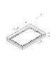
図1は、本発明の一実施形態のガラス溶着体の斜視図である。図1に示されるように、ガラス溶着体1は、板状のガラス部材(第1のガラス部材)4と、ガラス部材4に重ね合わされた板状のガラス部材(第2のガラス部材)5と、ガラス部材4とガラス部材5とを溶着した状態で、ガラス部材4とガラス部材5との間において溶着予定領域Rに沿って環状に延在するガラス層3と、を備えている。ガラス溶着体1は、例えば有機ELディスプレイであり、溶着予定領域Rの内側に形成された発光素子領域がガラス部材4,5及びガラス層3によって外部雰囲気から封止されている。ガラス部材4,5は、例えば無アルカリガラスからなる厚さ0.7mmの矩形板状の部材である。溶着予定領域Rは、ガラス部材4,5の外縁に沿うように所定の幅で矩形環状に設定されている。ガラス層3は、例えば低融点ガラス(バナジウムリン酸系ガラス、鉛ホウ酸ガラス等)からなる層である。
FIG. 1 is a perspective view of a glass welded body according to an embodiment of the present invention. As shown in FIG. 1, the glass welded body 1 includes a plate-like glass member (first glass member) 4, and a plate-like glass member (second glass member) 5 superimposed on the
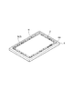
図2は、図1のII−II線に沿ってのガラス溶着体の断面図である。図2に示されるように、ガラス部材4及びガラス部材5は、ガラス層3が介在する領域に対応する環状部分4c,5cでのガラス部材4とガラス部材5との距離が中央部分4m,5m及び外縁部分4f,5fでのガラス部材4とガラス部材5との距離よりも大きくなるように(ここでは、ガラス層3が介在する領域の全部においてガラス部材4とガラス部材5との距離が最大となるように)、変形している。より具体的には、ガラス部材4は、ガラス層3に対向する環状部分4cからガラス部材4の中央部分4mに向かって凹むと共に、ガラス層3に対向する環状部分4cからガラス部材4の外縁部分4fに向かって凹むように、湾曲している。これにより、ガラス部材4の環状部分4cには、ガラス部材4の内側表面4aにおいて圧縮応力が生じ、ガラス部材4の外側表面4bにおいて引張応力が生じている(図2の矢印参照)。同様に、ガラス部材5は、ガラス層3に対向する環状部分5cからガラス部材5の中央部分5mに向かって凹むと共に、ガラス層3に対向する環状部分5cからガラス部材5の外縁部分5fに向かって凹むように、湾曲している。これにより、ガラス部材5の環状部分5cには、ガラス部材5の内側表面5aにおいて圧縮応力が生じ、ガラス部材5の外側表面5bにおいて引張応力が生じている(図2の矢印参照)。
FIG. 2 is a cross-sectional view of the glass welded body taken along line II-II in FIG. As shown in FIG. 2, the
なお、中央部分4mは、ガラス部材4のうち、ガラス層3が介在する領域に対応する環状部分4cの内側に位置する部分であり、外縁部分4fは、ガラス部材4のうち、ガラス層3が介在する領域に対応する環状部分4cの外側に位置する部分である。同様に、中央部分5mは、ガラス部材5のうち、ガラス層3が介在する領域に対応する環状部分5cの内側に位置する部分であり、外縁部分5fは、ガラス部材5のうち、ガラス層3が介在する領域に対応する環状部分5cの外側に位置する部分である。また、ガラス部材4,5及びガラス層3によって外部雰囲気から封止された領域は、外部雰囲気に対して減圧されていてもよいし、減圧されていなくてもよい。
In addition, the
次に、ガラス部材4とガラス部材5とを溶着してガラス溶着体1を製造するためのガラス溶着方法及びガラス溶着装置について説明する。図3及び図4は、本発明の一実施形態のガラス溶着方法を説明するための斜視図であり、図5及び図6は、本発明の一実施形態のガラス溶着装置の構成図である。
Next, a glass welding method and a glass welding apparatus for manufacturing the glass welded body 1 by welding the
まず、図3に示されるように、ディスペンサやスクリーン印刷等によってフリットペーストを塗布することにより、溶着予定領域Rに沿ってガラス部材4の内側表面4aにペースト層6を形成する。フリットペーストは、例えば、低融点ガラス(バナジウムリン酸系ガラス、鉛ホウ酸ガラス等)からなる粉末状のガラスフリット(ガラス粉)2、酸化鉄等の無機顔料であるレーザ光吸収性顔料(レーザ光吸収材)、酢酸アミル等である有機溶剤及びガラスの軟化点温度以下で熱分解する樹脂成分(アクリル等)であるバインダを混練したものである。
First, as shown in FIG. 3, a
続いて、ペースト層6を乾燥させて有機溶剤を除去する。そして、図4に示されるように、溶着予定領域Rに沿ってレーザ光L1の照射領域が相対的に移動するように、ガラスフリット2、レーザ光吸収性顔料及びバインダを含むガラス層3にレーザ光L1を照射することにより、バインダをガス化すると共にガラスフリット2を溶融させて、ガラス部材4の内側表面4aにガラス層3を定着させる(仮焼成)。これにより、レーザ光吸収性顔料を含むガラス層3が、環状に延在する溶着予定領域Rに沿うようにガラス部材4に配置されることになる。なお、加熱炉においてバインダをガス化すると共にガラスフリット2を溶融させて、ガラス部材4の内側表面4aにガラス層3を定着させてもよい。
Subsequently, the
続いて、図5に示されるように、溶着予定領域Rに沿うようにガラス層3が配置されたガラス部材4を、ガラス溶着装置11の載置台12に載置する。載置台12は、ガラス部材4の外側表面4bが接触した状態でガラス部材4が載置される平坦面12aを有している。そして、載置台12に載置されたガラス部材4に、ガラス層3を介してガラス部材5を重ね合わせる(第1の工程)。なお、ガラス部材5の内側表面5aには、発光素子領域が形成されている。
Subsequently, as shown in FIG. 5, the
続いて、ガラス溶着装置11の押圧治具13を用いて、ガラス部材5を載置台12側に押圧する(第1の工程)。押圧治具13は、溶着予定領域Rの内側に位置する領域に対向する凸面(第1の凸面)13aと、溶着予定領域Rに対向する凹面13bと、溶着予定領域Rの外側において溶着予定領域Rに沿う領域に対向する凸面(第2の凸面)13cと、を有し、石英等の光透過性材料からなる。これにより、図6に示されるように、少なくともガラス部材5は、ガラス層3が介在する領域に対応する環状部分4cでのガラス部材4とガラス部材5との距離が中央部分4m,5m及び外縁部分4f,5fでのガラス部材4とガラス部材5との距離よりも大きくなるように、変形させられる(第1の工程)。ここでは、ガラス部材5の外側表面5bに接触する凸面13a、凹面13b及び凸面13cが、連続する曲面として形成されているので、ガラス部材5は、ガラス層3に対向する環状部分5cから中央部分5mに向かって凹むと共に、ガラス層3に対向する環状部分5cから外縁部分5fに向かって凹むように、湾曲する。
Subsequently, the
ガラス溶着装置11では、載置台12及び押圧治具13によってガラス部材支持部14が構成されている。従って、ガラス部材支持部14は、溶着予定領域Rに沿うようにガラス層3が配置されたガラス部材4に、ガラス層3を介してガラス部材5が重ね合わされた状態で、且つ、ガラス層3が介在する領域に対応する環状部分4cでのガラス部材4とガラス部材5との距離が中央部分4m,5m及び外縁部分4f,5fでのガラス部材4とガラス部材5との距離よりも大きくなるように、少なくともガラス部材5が変形させられた状態で、ガラス部材4及びガラス部材5を支持する。
In the
続いて、ガラス部材支持部14によってガラス部材4,5が支持された状態(すなわち、少なくともガラス部材5が変形させられた状態)で、ガラス溶着装置11のレーザ光照射部15を用いて、溶着予定領域Rに沿ってレーザ光Lの照射領域が相対的に移動するようにガラス層3にレーザ光Lを照射する。そして、これにより、溶着予定領域Rに沿ってガラス層3及びその周辺部分(ガラス部材4,5の内側表面4a,5a部分)を溶融させて、ガラス部材4とガラス部材5とを溶着する(第2の工程)。より具体的には、レーザ光Lの集光スポットがガラス部材5とガラス層3との界面に位置するように、押圧治具13及びガラス部材5を介してガラス層3にレーザ光Lを照射する。ガラス部材4とガラス部材5とは、溶着予定領域Rに沿ってガラス層3及びその周辺部分が溶融・再固化することにより、溶着される。これにより、図1及び図2に示されるように、ガラス溶着体1が得られる。なお、ガラス部材4とガラス部材5との溶着においては、ガラス層3が溶融し、ガラス部材4,5の少なくとも一方が溶融しない場合もある。
Subsequently, welding is performed using the laser
このように、レーザ光照射部15は、溶着予定領域Rに沿ってガラス層3を溶融させてガラス部材4とガラス部材5とを溶着するために、ガラス部材支持部14によってガラス部材4,5が支持された状態で、溶着予定領域Rに沿ってレーザ光Lの照射領域が相対的に移動するようにガラス層3にレーザ光Lを照射する。
Thus, in order to melt the
以上説明したように、ガラス溶着体1を製造するためのガラス溶着方法及びガラス溶着装置11では、ガラス層3が介在する領域に対応する環状部分4cでのガラス部材4とガラス部材5との距離が中央部分4m,5m及び外縁部分4f,5fでのガラス部材4とガラス部材5との距離よりも大きくなるように、少なくともガラス部材5を変形させ、その状態で、溶着予定領域Rに沿ってガラス層3にレーザ光Lを照射することにより、溶着予定領域Rに沿ってガラス層3を溶融させてガラス部材4とガラス部材5とを溶着する。これにより、製造されたガラス溶着体1においては、ガラス層3に圧縮応力が生じるようにガラス部材4,5に応力が残留し、ガラス層3に亀裂が発生し難くなる。よって、上述したガラス溶着方法及びガラス溶着装置11によれば、ガラス層3での亀裂の発生が抑制されたガラス溶着体1を得ることができる。
As described above, in the glass welding method and the
ここで、図2に示されるように、ガラス溶着体1では、ガラス層3が介在する領域に対応する環状部分4cでのガラス部材4とガラス部材5との距離が中央部分4m,5m及び外縁部分4f,5fでのガラス部材4とガラス部材5との距離よりも大きくなるように、ガラス部材4,5が変形しているので、ガラス層3に引張応力が生じることが抑制され、ガラス層3に亀裂が発生し難くなる。よって、ガラス溶着体1によれば、ガラス層3での亀裂の発生が抑制される。
Here, as shown in FIG. 2, in the glass welded body 1, the distance between the
また、上述したガラス溶着方法及びガラス溶着装置11では、ガラス部材4を載置台12に載置し、押圧治具13を用いて、ガラス部材5を載置台12側に押圧する。これにより、ガラス層3が介在する領域に対応する環状部分4cでのガラス部材4とガラス部材5との距離が中央部分4m,5m及び外縁部分4f,5fでのガラス部材4とガラス部材5との距離よりも大きくなるように、少なくともガラス部材5を容易に且つ確実に変形させることができる。
Moreover, in the glass welding method and the
また、上述したガラス溶着方法及びガラス溶着装置11では、レーザ光照射部15を用いて、押圧治具13及びガラス部材5を介してガラス層3にレーザ光Lを照射する。これにより、溶着予定領域Rに沿ってガラス層3にレーザ光Lを容易に且つ確実に照射することができる。
In the glass welding method and the
更に、上述したガラス溶着方法及びガラス溶着装置11では、載置台12が、ガラス層3が配置されたガラス部材4が載置される平坦面12aを有している。そして、押圧治具13が、溶着予定領域Rの内側に位置する領域に対向する凸面13aと、溶着予定領域Rに対向する凹面13bと、溶着予定領域Rの外側において溶着予定領域Rに沿う領域に対向する凸面13cと、を有しており、ガラス部材5を押圧する。これにより、ガラス層3が介在する領域に対応する環状部分4cでのガラス部材4とガラス部材5との距離が中央部分4m,5m及び外縁部分4f,5fでのガラス部材4とガラス部材5との距離よりも大きくなるように、少なくともガラス部材5を変形させる際に、ガラス層3が配置されたガラス部材4の変形が抑制される一方で、ガラス部材5の変形が促進される。そのため、ガラス層3及びガラス部材4に無理な力が生じるのを防止しつつ、ガラス部材5を変形させることができる。
Furthermore, in the glass welding method and the
なお、仮に、平板状の押圧部材を用いてガラス部材5をガラス部材4に押圧し、その状態で、レーザ光Lの照射を実施すると、製造されたガラス溶着体においては、ガラス層3が介在する領域の全部においてガラス部材4とガラス部材5との距離が最小となるように、ガラス部材4,5の少なくとも一方が変形してしまう。この場合、ガラス層3に引張応力が生じるようにガラス部材4,5に応力が残留するので、ガラス層3に亀裂が発生し易くなってしまう。
If the
また、仮に、溶着予定領域Rに沿って移動可能な押圧部材を用いて、レーザ光Lの照射領域の両側の領域(すなわち、ガラス層3が介在する領域の一部)においてガラス部材4,5の少なくとも一方を変形させつつ、レーザ光Lの照射を実施すると、レーザ光Lの照射領域が溶着予定領域Rの角部を通過する際の押圧部材の移動制御が困難となってしまう。また、製造されたガラス溶着体においては、ガラス部材4,5の少なくとも一方の変形の度合いが、ガラス層3が介在する領域の全部において均一化されず、ガラス部材4,5が歪んでしまう。
Further, suppose that the
以上、本発明の一実施形態について説明したが、本発明は、上記実施形態に限定されるものではない。例えば、レーザ光吸収性顔料(レーザ光吸収材)は、ガラスフリット(ガラス粉)2自体に含まれていてもよい。また、ガラスフリット(ガラス粉)2は、ガラス部材4,5の融点よりも低い融点を有するものに限定されず、ガラス部材4,5の融点以上の融点を有するものであってもよい。また、溶着予定領域Rは、矩形環状に限定されず、環状であれば、他の形状であってもよい。このように、上述したガラス溶着方法、ガラス溶着装置11及びガラス溶着体1に適用される各構成の形状や材料としては、上述したもの限定されず、様々な形状や材料を適用することができる。
Although one embodiment of the present invention has been described above, the present invention is not limited to the above embodiment. For example, the laser light absorbing pigment (laser light absorbing material) may be contained in the glass frit (glass powder) 2 itself. Further, the glass frit (glass powder) 2 is not limited to one having a melting point lower than the melting point of the
また、図7及び図8に示されるように、押圧治具13は、石英等の光透過性材料からなる平板状の光透過部材16と、可撓性の光透過性材料からなる袋体17と、を有するものであってもよい。この場合には、袋体17をガラス部材5の外側表面5bに接触させて、袋体17内に空気等のガスを供給することにより、ガラス層3が介在する領域に対応する環状部分4cでのガラス部材4とガラス部材5との距離が中央部分4m,5m及び外縁部分4f,5fでのガラス部材4とガラス部材5との距離よりも大きくなるように、少なくともガラス部材5を変形させることができる。
7 and 8, the pressing
また、図9及び図10に示されるように、押圧治具13は、石英等の光透過性材料からなる平板状の光透過部材16と、樹脂等からなる凸部18,19と、を有するものであってもよい。凸部18は、溶着予定領域Rの内側に位置する領域に対向しており、凸部19は、溶着予定領域Rの外側において溶着予定領域Rに沿う領域に対向している。この場合には、凸部18,19をガラス部材5の外側表面5bに接触させて、光透過部材16を載置台12側に移動させることにより、ガラス層3が介在する領域に対応する環状部分4cでのガラス部材4とガラス部材5との距離が中央部分4m,5m及び外縁部分4f,5fでのガラス部材4とガラス部材5との距離よりも大きくなるように、少なくともガラス部材5を変形させることができる。なお、ガラス部材5に応力が集中してガラス部材5が損傷するのを防止する観点から、凸部18,19の角部は、丸められていることが好ましい。
As shown in FIGS. 9 and 10, the pressing
また、載置台12は、溶着予定領域Rの内側に位置する領域に対向する第1の凸面と、溶着予定領域Rに対向する凹面と、溶着予定領域Rの外側において溶着予定領域Rに沿う領域に対向する第2の凸面と、を有していてもよい。その場合、押圧治具13は、凸面13a、凹面13b及び凸面13cを有していてもよいし、それらの代わりに、平坦面を有していてもよい。また、載置台12にガラス部材5を載置し、押圧治具13を用いて、ガラス層3を介してガラス部材5に重ね合わされたガラス部材4を載置台12側に押圧してもよい。その場合には、レーザ光Lの照射を、ガラス部材4を介して実施することになる。このように、溶着予定領域Rに沿うようにガラス層3が配置されたガラス部材4に、ガラス層3を介してガラス部材5を重ね合わせ、ガラス層3が介在する領域に対応する環状部分4cでのガラス部材4とガラス部材5との距離が中央部分4m,5m及び外縁部分4f,5fでのガラス部材4とガラス部材5との距離よりも大きくなるように、ガラス部材4,5の少なくとも一方を変形させることができれば、載置台12や押圧治具13の形状等は、上述したものに限定されない。
Further, the mounting table 12 includes a first convex surface facing the region located inside the planned welding region R, a concave surface facing the planned welding region R, and a region along the planned welding region R outside the planned welding region R. And a second convex surface facing the surface. In that case, the pressing
また、図11に示されるように、複数のガラス部材4を含むガラス基板と、複数のガラス部材5を含むガラス基板とを重ね合わせ、対向するガラス部材4,5ごとに設定された溶着予定領域Rに沿ってガラス部材4,5同士を溶着し、その後に、対向するガラス部材4,5ごとにガラス基板を切断するようにしてもよい。ここでは、ガラス部材4,5同士を溶着する際に、溶着予定領域Rの内側に位置する領域に対向する平坦な凸面(第1の凸面)21と、溶着予定領域Rの外側において溶着予定領域Rに沿う領域に対向する平坦な凸面(第2の凸面)22と、溶着予定領域Rに対向する平坦な凹面(凸面21と凸面22との間の面)と、を有する押圧治具を用いて、ガラス部材4,5の一方をガラス部材4,5の他方に押圧する。
Moreover, as shown in FIG. 11, a glass substrate including a plurality of
このとき、凸面22は、隣り合う溶着予定領域R,R間に位置することになるので、凸面22の面積は、凸面21の面積に比べて小さくなる。そのため、凸面22によってガラス部材4,5の一方に付与される圧力は、凸面21によってガラス部材4,5の一方に付与される圧力に比べて大きくなる。そこで、凸面21と溶着予定領域Rとの間の距離W1に比べ、凸面22と溶着予定領域Rとの間の距離W2を小さくすれば、ガラス部材4,5の一方において、溶着予定領域Rの内側に位置する領域の変形量と、溶着予定領域Rの外側において溶着予定領域Rに沿う領域の変形量とを同程度に調整することができる。
At this time, since the
1…ガラス溶着体、3…ガラス層、4…ガラス部材(第1のガラス部材)、5…ガラス部材(第2のガラス部材)、11…ガラス溶着装置、12…載置台、12a…平坦面、13…押圧治具、13a…凸面(第1の凸面)、13b…凹面、13c…凸面(第2の凸面)、14…ガラス部材支持部、15…レーザ光照射部、21…凸面(第1の凸面)、22…凸面(第2の凸面)、L…レーザ光。 DESCRIPTION OF SYMBOLS 1 ... Glass welded body, 3 ... Glass layer, 4 ... Glass member (1st glass member), 5 ... Glass member (2nd glass member), 11 ... Glass welding apparatus, 12 ... Mounting stand, 12a ... Flat surface , 13 ... pressing jig, 13a ... convex surface (first convex surface), 13b ... concave surface, 13c ... convex surface (second convex surface), 14 ... glass member support portion, 15 ... laser light irradiation portion, 21 ... convex surface (first surface) 1 convex surface), 22... Convex surface (second convex surface), L... Laser light.
Claims (12)
環状に延在する溶着予定領域に沿うようにガラス層が配置された前記第1のガラス部材に、前記ガラス層を介して前記第2のガラス部材を重ね合わせ、前記ガラス層が介在する領域に対応する環状部分での前記第1のガラス部材と前記第2のガラス部材との距離が中央部分及び外縁部分での前記第1のガラス部材と前記第2のガラス部材との距離よりも大きくなるように、且つ前記環状部分から前記中央部分に向かって前記第1のガラス部材と前記第2のガラス部材との距離が変化する部分の幅が前記環状部分の幅よりも大きくなるように、前記第1のガラス部材及び前記第2のガラス部材の少なくとも一方を変形させる第1の工程と、
前記第1の工程の後に、前記第1のガラス部材及び前記第2のガラス部材の少なくとも一方を変形させた状態で、前記溶着予定領域に沿ってレーザ光の照射領域が相対的に移動するように前記ガラス層に前記レーザ光を照射することにより、前記溶着予定領域に沿って前記ガラス層を溶融させて前記第1のガラス部材と前記第2のガラス部材とを溶着する第2の工程と、を備える、ガラス溶着方法。 A glass welding method for producing a glass welded body by welding a plate-like first glass member and a plate-like second glass member,
The second glass member is overlaid on the first glass member in which the glass layer is arranged so as to extend along the annular welding planned region, and the glass layer is interposed in the region where the glass layer is interposed. The distance between the first glass member and the second glass member at the corresponding annular portion is larger than the distance between the first glass member and the second glass member at the center portion and the outer edge portion. And the width of the portion where the distance between the first glass member and the second glass member changes from the annular portion toward the central portion is larger than the width of the annular portion. A first step of deforming at least one of the first glass member and the second glass member;
After the first step, in a state where at least one of the first glass member and the second glass member is deformed, the irradiation region of the laser beam relatively moves along the planned welding region. Irradiating the glass layer with the laser beam to melt the glass layer along the planned welding region and welding the first glass member and the second glass member; A glass welding method.
前記押圧治具は、前記溶着予定領域の内側に位置する領域に対向する第1の凸面と、前記溶着予定領域に対向する凹面と、前記溶着予定領域の外側において前記溶着予定領域に沿う領域に対向する第2の凸面と、を有し、前記第2のガラス部材を押圧する、請求項2又は3記載のガラス溶着方法。 The mounting table has a flat surface on which the first glass member is mounted,
The pressing jig includes a first convex surface facing a region located inside the planned welding region, a concave surface facing the planned welding region, and a region along the planned welding region outside the planned welding region. The glass welding method according to claim 2, further comprising a second convex surface facing each other and pressing the second glass member.
環状に延在する溶着予定領域に沿うようにガラス層が配置された前記第1のガラス部材に、前記ガラス層を介して前記第2のガラス部材が重ね合わされた状態で、且つ、前記ガラス層が介在する領域に対応する環状部分での前記第1のガラス部材と前記第2のガラス部材との距離が中央部分及び外縁部分での前記第1のガラス部材と前記第2のガラス部材との距離よりも大きくなるように、且つ前記環状部分から前記中央部分に向かって前記第1のガラス部材と前記第2のガラス部材との距離が変化する部分の幅が前記環状部分の幅よりも大きくなるように、前記第1のガラス部材及び前記第2のガラス部材の少なくとも一方が変形させられた状態で、前記第1のガラス部材及び前記第2のガラス部材を支持するガラス部材支持部と、
前記溶着予定領域に沿って前記ガラス層を溶融させて前記第1のガラス部材と前記第2のガラス部材とを溶着するために、前記ガラス部材支持部によって前記第1のガラス部材及び前記第2のガラス部材が支持された状態で、前記溶着予定領域に沿ってレーザ光の照射領域が相対的に移動するように前記ガラス層に前記レーザ光を照射するレーザ光照射部と、を備える、ガラス溶着装置。 A glass welding apparatus for producing a glass welded body by welding a plate-like first glass member and a plate-like second glass member,
The glass layer in a state in which the second glass member is superimposed on the first glass member in which the glass layer is disposed so as to extend along the annular welding planned region. The distance between the first glass member and the second glass member at the annular portion corresponding to the region where the intervenes are between the first glass member and the second glass member at the center portion and the outer edge portion. The width of the portion where the distance between the first glass member and the second glass member changes from the annular portion toward the central portion is larger than the width of the annular portion so as to be larger than the distance. In a state where at least one of the first glass member and the second glass member is deformed, a glass member support portion that supports the first glass member and the second glass member,
In order to fuse the first glass member and the second glass member by melting the glass layer along the planned welding region, the first glass member and the second glass member are supported by the glass member support portion. A laser beam irradiation unit configured to irradiate the glass layer with the laser beam so that an irradiation region of the laser beam relatively moves along the planned welding region in a state where the glass member is supported. Welding equipment.
前記押圧治具は、前記溶着予定領域の内側に位置する領域に対向する第1の凸面と、前記溶着予定領域に対向する凹面と、前記溶着予定領域の外側において前記溶着予定領域に沿う領域に対向する第2の凸面と、を有し、前記第2のガラス部材を押圧する、請求項6又は7記載のガラス溶着装置。 The mounting table has a flat surface on which the first glass member is mounted,
The pressing jig includes a first convex surface facing a region located inside the planned welding region, a concave surface facing the planned welding region, and a region along the planned welding region outside the planned welding region. The glass welding apparatus of Claim 6 or 7 which has a 2nd convex surface which opposes, and presses the said 2nd glass member.
前記第1のガラス部材に重ね合わされた板状の第2のガラス部材と、
前記第1のガラス部材と前記第2のガラス部材とを溶着した状態で、前記第1のガラス部材と前記第2のガラス部材との間において環状に延在するガラス層と、を備え、
前記ガラス層が介在する領域に対応する環状部分での前記第1のガラス部材と前記第2のガラス部材との距離が中央部分及び外縁部分での前記第1のガラス部材と前記第2のガラス部材との距離よりも大きくなるように、且つ前記環状部分から前記中央部分に向かって前記第1のガラス部材と前記第2のガラス部材との距離が変化する部分の幅が前記環状部分の幅よりも大きくなるように、前記第1のガラス部材及び前記第2のガラス部材の少なくとも一方が変形している、ガラス溶着体。 A plate-like first glass member;
A plate-like second glass member superimposed on the first glass member;
A glass layer extending annularly between the first glass member and the second glass member in a state in which the first glass member and the second glass member are welded,
The distance between the first glass member and the second glass member at the annular portion corresponding to the region where the glass layer is interposed is the first glass member and the second glass at the central portion and the outer edge portion. The width of the portion where the distance between the first glass member and the second glass member changes from the annular portion toward the central portion so as to be larger than the distance to the member is the width of the annular portion. A glass welded body in which at least one of the first glass member and the second glass member is deformed so as to be larger .
環状に延在する溶着予定領域に沿うようにガラス層が配置された前記第1のガラス部材に、前記ガラス層を介して前記第2のガラス部材を重ね合わせ、前記ガラス層が介在する領域に対応する環状部分において前記第1のガラス部材と前記第2のガラス部材との距離が最大となるように、且つ前記環状部分から中央部分に向かって前記第1のガラス部材と前記第2のガラス部材との距離が変化する部分の幅が前記環状部分の幅よりも大きくなるように、前記第1のガラス部材及び前記第2のガラス部材の少なくとも一方を変形させる第1の工程と、
前記第1の工程の後に、前記第1のガラス部材及び前記第2のガラス部材の少なくとも一方を変形させた状態で、前記溶着予定領域に沿ってレーザ光の照射領域が相対的に移動するように前記ガラス層に前記レーザ光を照射することにより、前記溶着予定領域に沿って前記ガラス層を溶融させて前記第1のガラス部材と前記第2のガラス部材とを溶着する第2の工程と、を備える、ガラス溶着方法。 A glass welding method for producing a glass welded body by welding a plate-like first glass member and a plate-like second glass member,
The second glass member is overlaid on the first glass member in which the glass layer is arranged so as to extend along the annular welding planned region, and the glass layer is interposed in the region where the glass layer is interposed. The first glass member and the second glass so that the distance between the first glass member and the second glass member is maximized in the corresponding annular portion and from the annular portion toward the central portion. A first step of deforming at least one of the first glass member and the second glass member such that the width of the portion where the distance to the member changes is larger than the width of the annular portion ;
After the first step, in a state where at least one of the first glass member and the second glass member is deformed, the irradiation region of the laser beam relatively moves along the planned welding region. Irradiating the glass layer with the laser beam to melt the glass layer along the planned welding region and welding the first glass member and the second glass member; A glass welding method.
環状に延在する溶着予定領域に沿うようにガラス層が配置された前記第1のガラス部材に、前記ガラス層を介して前記第2のガラス部材が重ね合わされた状態で、且つ、前記ガラス層が介在する領域に対応する環状部分において前記第1のガラス部材と前記第2のガラス部材との距離が最大となるように、且つ前記環状部分から中央部分に向かって前記第1のガラス部材と前記第2のガラス部材との距離が変化する部分の幅が前記環状部分の幅よりも大きくなるように、前記第1のガラス部材及び前記第2のガラス部材の少なくとも一方が変形させられた状態で、前記第1のガラス部材及び前記第2のガラス部材を支持するガラス部材支持部と、
前記溶着予定領域に沿って前記ガラス層を溶融させて前記第1のガラス部材と前記第2のガラス部材とを溶着するために、前記ガラス部材支持部によって前記第1のガラス部材及び前記第2のガラス部材が支持された状態で、前記溶着予定領域に沿ってレーザ光の照射領域が相対的に移動するように前記ガラス層に前記レーザ光を照射するレーザ光照射部と、を備える、ガラス溶着装置。 A glass welding apparatus for producing a glass welded body by welding a plate-like first glass member and a plate-like second glass member,
The glass layer in a state in which the second glass member is superimposed on the first glass member in which the glass layer is disposed so as to extend along the annular welding planned region. The first glass member and the first glass member so that the distance between the first glass member and the second glass member is maximized in the annular portion corresponding to the region where the intermediate portion is interposed, and from the annular portion toward the central portion. A state in which at least one of the first glass member and the second glass member is deformed so that the width of the portion where the distance to the second glass member changes is larger than the width of the annular portion. And the glass member support part which supports the 1st glass member and the 2nd glass member,
In order to fuse the first glass member and the second glass member by melting the glass layer along the planned welding region, the first glass member and the second glass member are supported by the glass member support portion. A laser beam irradiation unit configured to irradiate the glass layer with the laser beam so that an irradiation region of the laser beam relatively moves along the planned welding region in a state where the glass member is supported. Welding equipment.
前記第1のガラス部材に重ね合わされた板状の第2のガラス部材と、
前記第1のガラス部材と前記第2のガラス部材とを溶着した状態で、前記第1のガラス部材と前記第2のガラス部材との間において環状に延在するガラス層と、を備え、
前記ガラス層が介在する領域に対応する環状部分において前記第1のガラス部材と前記第2のガラス部材との距離が最大となるように、且つ前記環状部分から中央部分に向かって前記第1のガラス部材と前記第2のガラス部材との距離が変化する部分の幅が前記環状部分の幅よりも大きくなるように、前記第1のガラス部材及び前記第2のガラス部材の少なくとも一方が変形している、ガラス溶着体。 A plate-like first glass member;
A plate-like second glass member superimposed on the first glass member;
A glass layer extending annularly between the first glass member and the second glass member in a state in which the first glass member and the second glass member are welded,
In the annular portion corresponding to the region where the glass layer is interposed, the first glass member and the second glass member have a maximum distance from the annular portion toward the central portion. At least one of the first glass member and the second glass member is deformed so that the width of the portion where the distance between the glass member and the second glass member changes is larger than the width of the annular portion. The glass welded body.
Priority Applications (1)
| Application Number | Priority Date | Filing Date | Title |
|---|---|---|---|
| JP2012076725A JP5984452B2 (en) | 2012-03-29 | 2012-03-29 | Glass welding method, glass welding apparatus and glass welded body |
Applications Claiming Priority (1)
| Application Number | Priority Date | Filing Date | Title |
|---|---|---|---|
| JP2012076725A JP5984452B2 (en) | 2012-03-29 | 2012-03-29 | Glass welding method, glass welding apparatus and glass welded body |
Publications (3)
| Publication Number | Publication Date |
|---|---|
| JP2013203629A JP2013203629A (en) | 2013-10-07 |
| JP2013203629A5 JP2013203629A5 (en) | 2015-05-14 |
| JP5984452B2 true JP5984452B2 (en) | 2016-09-06 |
Family
ID=49523128
Family Applications (1)
| Application Number | Title | Priority Date | Filing Date |
|---|---|---|---|
| JP2012076725A Active JP5984452B2 (en) | 2012-03-29 | 2012-03-29 | Glass welding method, glass welding apparatus and glass welded body |
Country Status (1)
| Country | Link |
|---|---|
| JP (1) | JP5984452B2 (en) |
Cited By (1)
| Publication number | Priority date | Publication date | Assignee | Title |
|---|---|---|---|---|
| KR101838252B1 (en) * | 2016-12-23 | 2018-03-14 | 주식회사 비에스피 | Pressurizing module for glass to glass welding |
Families Citing this family (1)
| Publication number | Priority date | Publication date | Assignee | Title |
|---|---|---|---|---|
| DE102019119961A1 (en) | 2019-07-24 | 2021-01-28 | Schott Ag | Hermetically sealed, transparent cavity and its housing |
Family Cites Families (5)
| Publication number | Priority date | Publication date | Assignee | Title |
|---|---|---|---|---|
| JP4048909B2 (en) * | 2002-10-21 | 2008-02-20 | 松下電器産業株式会社 | Plasma display panel and manufacturing method thereof |
| JP2009070687A (en) * | 2007-09-13 | 2009-04-02 | Canon Inc | Manufacturing method of airtight container |
| JP2009199773A (en) * | 2008-02-19 | 2009-09-03 | Toshiba Mobile Display Co Ltd | Manufacturing apparatus for display device |
| JP5697385B2 (en) * | 2009-10-30 | 2015-04-08 | キヤノン株式会社 | Glass substrate bonded body, hermetic container, and method for manufacturing glass structure |
| JP2012209133A (en) * | 2011-03-30 | 2012-10-25 | Canon Inc | Airtight container, image display device, and manufacturing method thereof |
-
2012
- 2012-03-29 JP JP2012076725A patent/JP5984452B2/en active Active
Cited By (1)
| Publication number | Priority date | Publication date | Assignee | Title |
|---|---|---|---|---|
| KR101838252B1 (en) * | 2016-12-23 | 2018-03-14 | 주식회사 비에스피 | Pressurizing module for glass to glass welding |
Also Published As
| Publication number | Publication date |
|---|---|
| JP2013203629A (en) | 2013-10-07 |
Similar Documents
| Publication | Publication Date | Title |
|---|---|---|
| JP5481167B2 (en) | Glass welding method | |
| US20120248950A1 (en) | Hermetically sealed container, image display apparatus, and their manufacturing methods | |
| WO2011065108A1 (en) | Glass welding method and glass layer fixing method | |
| JP4928483B2 (en) | Glass welding method | |
| JP5308461B2 (en) | Glass envelope sealing method | |
| JP5466929B2 (en) | Glass welding method and glass layer fixing method | |
| WO2017170380A1 (en) | Glass panel unit manufacturing method, fitting manufacturing method, glass panel unit manufacturing device, and glass panel unit | |
| JP4942207B2 (en) | Airtight container manufacturing method | |
| JP2012176898A (en) | Method for fixing glass layer | |
| JP5984452B2 (en) | Glass welding method, glass welding apparatus and glass welded body | |
| JP2008284782A (en) | Resin-glass fused adhesion method and resin-glass fused adhesion apparatus | |
| JP5869946B2 (en) | Glass welding method | |
| JP2012226978A (en) | Manufacturing method of air tight container and image display apparatus | |
| JP5535767B2 (en) | Glass welding method | |
| JP2006318862A (en) | Manufacturing method of vacuum display panel | |
| JP2012190607A (en) | Manufacturing method of hermetic container | |
| WO2018221396A1 (en) | Method for producing glass panel unit | |
| JP5492049B2 (en) | Glass welding method | |
| JP5882114B2 (en) | Glass welding method | |
| JP5498310B2 (en) | Glass welding method | |
| JP2013203629A5 (en) | ||
| JP2012121758A (en) | Glass welding device and glass welding method | |
| JP6796812B2 (en) | Manufacturing method of glass panel unit and manufacturing method of glass window | |
| JPWO2012161151A1 (en) | ORGANIC EL ELEMENT AND METHOD FOR PRODUCING ORGANIC EL ELEMENT | |
| JP2012031032A (en) | Glass fusing method |
Legal Events
| Date | Code | Title | Description |
|---|---|---|---|
| A521 | Request for written amendment filed |
Free format text: JAPANESE INTERMEDIATE CODE: A523 Effective date: 20150330 |
|
| A621 | Written request for application examination |
Free format text: JAPANESE INTERMEDIATE CODE: A621 Effective date: 20150330 |
|
| A977 | Report on retrieval |
Free format text: JAPANESE INTERMEDIATE CODE: A971007 Effective date: 20151030 |
|
| A131 | Notification of reasons for refusal |
Free format text: JAPANESE INTERMEDIATE CODE: A131 Effective date: 20151208 |
|
| A521 | Request for written amendment filed |
Free format text: JAPANESE INTERMEDIATE CODE: A523 Effective date: 20160208 |
|
| TRDD | Decision of grant or rejection written | ||
| A01 | Written decision to grant a patent or to grant a registration (utility model) |
Free format text: JAPANESE INTERMEDIATE CODE: A01 Effective date: 20160705 |
|
| A61 | First payment of annual fees (during grant procedure) |
Free format text: JAPANESE INTERMEDIATE CODE: A61 Effective date: 20160802 |
|
| R150 | Certificate of patent or registration of utility model |
Ref document number: 5984452 Country of ref document: JP Free format text: JAPANESE INTERMEDIATE CODE: R150 |
|
| R250 | Receipt of annual fees |
Free format text: JAPANESE INTERMEDIATE CODE: R250 |