JP5981475B2 - Laminated shaped article manufacturing apparatus and laminated shaped article manufacturing method - Google Patents
Laminated shaped article manufacturing apparatus and laminated shaped article manufacturing method Download PDFInfo
- Publication number
- JP5981475B2 JP5981475B2 JP2014054420A JP2014054420A JP5981475B2 JP 5981475 B2 JP5981475 B2 JP 5981475B2 JP 2014054420 A JP2014054420 A JP 2014054420A JP 2014054420 A JP2014054420 A JP 2014054420A JP 5981475 B2 JP5981475 B2 JP 5981475B2
- Authority
- JP
- Japan
- Prior art keywords
- layered object
- unevenness
- raw material
- manufacturing
- layers
- Prior art date
- Legal status (The legal status is an assumption and is not a legal conclusion. Google has not performed a legal analysis and makes no representation as to the accuracy of the status listed.)
- Active
Links
Images


Classifications
-
- B—PERFORMING OPERATIONS; TRANSPORTING
- B29—WORKING OF PLASTICS; WORKING OF SUBSTANCES IN A PLASTIC STATE IN GENERAL
- B29C—SHAPING OR JOINING OF PLASTICS; SHAPING OF MATERIAL IN A PLASTIC STATE, NOT OTHERWISE PROVIDED FOR; AFTER-TREATMENT OF THE SHAPED PRODUCTS, e.g. REPAIRING
- B29C64/00—Additive manufacturing, i.e. manufacturing of three-dimensional [3D] objects by additive deposition, additive agglomeration or additive layering, e.g. by 3D printing, stereolithography or selective laser sintering
- B29C64/10—Processes of additive manufacturing
- B29C64/141—Processes of additive manufacturing using only solid materials
- B29C64/153—Processes of additive manufacturing using only solid materials using layers of powder being selectively joined, e.g. by selective laser sintering or melting
-
- B—PERFORMING OPERATIONS; TRANSPORTING
- B22—CASTING; POWDER METALLURGY
- B22F—WORKING METALLIC POWDER; MANUFACTURE OF ARTICLES FROM METALLIC POWDER; MAKING METALLIC POWDER; APPARATUS OR DEVICES SPECIALLY ADAPTED FOR METALLIC POWDER
- B22F10/00—Additive manufacturing of workpieces or articles from metallic powder
- B22F10/20—Direct sintering or melting
-
- B—PERFORMING OPERATIONS; TRANSPORTING
- B22—CASTING; POWDER METALLURGY
- B22F—WORKING METALLIC POWDER; MANUFACTURE OF ARTICLES FROM METALLIC POWDER; MAKING METALLIC POWDER; APPARATUS OR DEVICES SPECIALLY ADAPTED FOR METALLIC POWDER
- B22F12/00—Apparatus or devices specially adapted for additive manufacturing; Auxiliary means for additive manufacturing; Combinations of additive manufacturing apparatus or devices with other processing apparatus or devices
-
- B—PERFORMING OPERATIONS; TRANSPORTING
- B22—CASTING; POWDER METALLURGY
- B22F—WORKING METALLIC POWDER; MANUFACTURE OF ARTICLES FROM METALLIC POWDER; MAKING METALLIC POWDER; APPARATUS OR DEVICES SPECIALLY ADAPTED FOR METALLIC POWDER
- B22F7/00—Manufacture of composite layers, workpieces, or articles, comprising metallic powder, by sintering the powder, with or without compacting wherein at least one part is obtained by sintering or compression
- B22F7/02—Manufacture of composite layers, workpieces, or articles, comprising metallic powder, by sintering the powder, with or without compacting wherein at least one part is obtained by sintering or compression of composite layers
-
- B—PERFORMING OPERATIONS; TRANSPORTING
- B33—ADDITIVE MANUFACTURING TECHNOLOGY
- B33Y—ADDITIVE MANUFACTURING, i.e. MANUFACTURING OF THREE-DIMENSIONAL [3-D] OBJECTS BY ADDITIVE DEPOSITION, ADDITIVE AGGLOMERATION OR ADDITIVE LAYERING, e.g. BY 3-D PRINTING, STEREOLITHOGRAPHY OR SELECTIVE LASER SINTERING
- B33Y10/00—Processes of additive manufacturing
-
- B—PERFORMING OPERATIONS; TRANSPORTING
- B22—CASTING; POWDER METALLURGY
- B22F—WORKING METALLIC POWDER; MANUFACTURE OF ARTICLES FROM METALLIC POWDER; MAKING METALLIC POWDER; APPARATUS OR DEVICES SPECIALLY ADAPTED FOR METALLIC POWDER
- B22F2998/00—Supplementary information concerning processes or compositions relating to powder metallurgy
- B22F2998/10—Processes characterised by the sequence of their steps
-
- B—PERFORMING OPERATIONS; TRANSPORTING
- B33—ADDITIVE MANUFACTURING TECHNOLOGY
- B33Y—ADDITIVE MANUFACTURING, i.e. MANUFACTURING OF THREE-DIMENSIONAL [3-D] OBJECTS BY ADDITIVE DEPOSITION, ADDITIVE AGGLOMERATION OR ADDITIVE LAYERING, e.g. BY 3-D PRINTING, STEREOLITHOGRAPHY OR SELECTIVE LASER SINTERING
- B33Y30/00—Apparatus for additive manufacturing; Details thereof or accessories therefor
-
- B—PERFORMING OPERATIONS; TRANSPORTING
- B33—ADDITIVE MANUFACTURING TECHNOLOGY
- B33Y—ADDITIVE MANUFACTURING, i.e. MANUFACTURING OF THREE-DIMENSIONAL [3-D] OBJECTS BY ADDITIVE DEPOSITION, ADDITIVE AGGLOMERATION OR ADDITIVE LAYERING, e.g. BY 3-D PRINTING, STEREOLITHOGRAPHY OR SELECTIVE LASER SINTERING
- B33Y80/00—Products made by additive manufacturing
-
- Y—GENERAL TAGGING OF NEW TECHNOLOGICAL DEVELOPMENTS; GENERAL TAGGING OF CROSS-SECTIONAL TECHNOLOGIES SPANNING OVER SEVERAL SECTIONS OF THE IPC; TECHNICAL SUBJECTS COVERED BY FORMER USPC CROSS-REFERENCE ART COLLECTIONS [XRACs] AND DIGESTS
- Y02—TECHNOLOGIES OR APPLICATIONS FOR MITIGATION OR ADAPTATION AGAINST CLIMATE CHANGE
- Y02P—CLIMATE CHANGE MITIGATION TECHNOLOGIES IN THE PRODUCTION OR PROCESSING OF GOODS
- Y02P10/00—Technologies related to metal processing
- Y02P10/25—Process efficiency
Description
本発明の実施形態は、積層造形物、その製造方法及び積層造形物の製造装置に関する。 Embodiments described herein relate generally to a layered object, a manufacturing method thereof, and a manufacturing apparatus for a layered object.
例えば、原料を供給しつつレーザなどでその原料を加熱して、その原料を溶融させて、所望の形状の造形物を形成する方法がある。造形物において、強度を向上することが望まれる。 For example, there is a method of forming a shaped article having a desired shape by heating the raw material with a laser or the like while supplying the raw material, and melting the raw material. It is desired to improve the strength of the shaped article.
本発明の実施形態は、高強度の積層造形物、その製造方法及び積層造形物の製造装置を提供する。 Embodiments of the present invention provide a high-strength layered object, a method for manufacturing the same, and a device for manufacturing a layered object.
本発明の実施形態によれば、第1部分と第2部分とを含む積層された複数の層により造形される積層造形物の製造装置が提供される。前記第1部分は、凹凸を有する第1面を有し、前記複数の層の一部である。前記第2部分は、前記第1面に接する。前記第2部分は、前記凹凸形状に沿う第2面と、前記第2面とは反対側の第3面と、を有し、前記複数の層の別の一部を含む。前記第3面は、前記凹凸よりも平坦な部分を含む。積層造形物の製造装置は、ヘッドを含む。ヘッドは、上面に凹凸が設けられた凹凸部材に向けて、原料を供給しつつ前記原料を加熱して溶解させ、前記凹凸部材との相対的な位置を変更可能である。 According to the embodiment of the present invention, there is provided an apparatus for manufacturing a layered object that is formed by a plurality of stacked layers including a first part and a second part . Before Symbol first portion has a first surface having irregularities, a part of the plurality of layers. The second portion is in contact with the first surface. The second portion has a second surface along the uneven shape and a third surface opposite to the second surface, and includes another part of the plurality of layers. The third surface includes a portion that is flatter than the unevenness. The manufacturing apparatus for the layered object includes a head. The head is capable of changing the relative position with the concavo-convex member by heating and melting the raw material while supplying the raw material toward the concavo-convex member having an uneven surface on the upper surface.
以下に、本発明の各実施の形態について図面を参照しつつ説明する。
なお、図面は模式的または概念的なものであり、各部分の厚みと幅との関係、部分間の大きさの比率などは、必ずしも現実のものと同一とは限らない。また、同じ部分を表す場合であっても、図面により互いの寸法や比率が異なって表される場合もある。
なお、本願明細書と各図において、既出の図に関して前述したものと同様の要素には同一の符号を付して詳細な説明は適宜省略する。
Embodiments of the present invention will be described below with reference to the drawings.
The drawings are schematic or conceptual, and the relationship between the thickness and width of each part, the size ratio between the parts, and the like are not necessarily the same as actual ones. Further, even when the same part is represented, the dimensions and ratios may be represented differently depending on the drawings.
Note that, in the present specification and each drawing, the same elements as those described above with reference to the previous drawings are denoted by the same reference numerals, and detailed description thereof is omitted as appropriate.
(第1の実施形態)
図1は、第1の実施形態に係る積層造形物を例示する模式的断面図である。
図1に表したように、本実施形態に係る積層造形物110は、積層された複数の層により造形される。この例では、積層造形物110は、第1部分10(層)と、第2部分20と、を含む。第1部分10は、複数の層の一部である。第1部分10は、例えば、層状である。第2部分20は、複数の層の別の一部である。第2部分20は、例えば、複数の層(層21〜層24など)を含む。第2部分20に含まれる層の数は、任意である。
(First embodiment)
FIG. 1 is a schematic cross-sectional view illustrating a layered object according to the first embodiment.
As shown in FIG. 1, the
積層造形物110に含まれる複数の層のそれぞれは、例えば、原料を供給しつつ、その原料をエネルギー線(例えばレーザ光)などで加熱して溶解することで形成される。積層造形物110は、複数の層を順次形成することで、形成される。積層造形物110の形成方法の例については、後述する。
Each of the plurality of layers included in the
第1部分10から第2部分20に向かう方向をZ軸方向とする。Z軸方向に対して垂直な1つの方向をX軸方向とする。Z軸方向とX軸方向とに対して垂直な方向をY軸方向とする。
A direction from the
積層造形物110において、複数の層のそれぞれは、X−Y平面内に延在する。複数の層がZ軸方向に積層される。複数の層のそれぞれのX−Y平面内の形状を変更することで、積層造形物110において、所望の形状が得られる。
In the
第1部分10は、第1面10aを有する、第1面10aは、第2部分20に対向する面である。第1面10aは、凹凸11を有する。
The
第2部分20は、第1面10aに接する。第2部分20は、第2面20aと、第3面20bと、を有する。第2面20aは、第1面10aの凹凸11と嵌合する。第2面20aは、第1面10aの形状に沿う。第3面20bは、第2面20aとは反対側の面である。
The
この例では、積層造形物110は、基体50の上に形成される。積層造形物110を形成した後に、基体50は除去されても良い。基体50の少なくとも一部が、積層造形物110に含まれても良い。基体50の材料は、積層造形物110の材料と同じでも良く、異なっても良い。
In this example, the
図2は、第1の実施形態に係る積層造形物の製造方法を例示する模式的断面図である。 図2に表したように、基体50の上に、第1部分10が設けられている。この図では、第1面10aの凹凸11は、省略されている。第1面10aに向けて、第2部分20の原料20mが供給される。原料20mとして、例えば、金属の粒子、または、樹脂の粒子などが用いられる。原料20mは、任意である。
FIG. 2 is a schematic cross-sectional view illustrating the method for manufacturing the layered object according to the first embodiment. As shown in FIG. 2, the
この例では、ヘッド60が用いられる。ヘッド60から原料20mが出射する。例えば、原料20mの進行方向を制御するために、シールドガス62がヘッド60から流出する。ヘッド60から、エネルギー線61(例えば、レーザ光)が出射する。
In this example, the
ヘッド60において、原料20mが第1面10aに向けて供給され、それと同時に、ヘッド60からエネルギー線61が出射する。その後、選択的な位置おいて、原料20mが溶融し、結合する。例えば、第1部分10のうちの、エネルギー線61が照射されている部分が局所的に加熱されることにより溶解領域68を形成させる。そこへ、原料20mが供給され、溶解し、結合する。エネルギー線61が原料20mに照射されて原料20mを溶解させてから、原料20mを第1部分10に供給されても良い。
In the
ヘッド60と基体50との相対的位置が、X−Y平面内で変化される。すなわち、熱エネルギーの発生位置を変更する。原料20mが供給されエネルギー線61が照射された位置において、原料20mから、第2部分20の一部(例えば層21)が形成される。X−Y平面内の位置を変えてこの動作を実施する。これにより、X−Y平面に延在する層(層21)が形成できる。この層が、第2部分20の一部となる。
The relative position between the
図3(a)〜図3(e)は、第1の実施形態に係る積層造形物の製造方法を例示する工程順模式的断面図である。
図3(a)に表したように、第1部分10を形成する。この例では、平坦な基体50の上に第1部分10を形成する。例えば、ヘッド60を用いて、基体50の上に原料20mを供給しつつ、エネルギー線61を照射する。これにより、表面が平坦な層が形成される。この平坦な層の選択的な位置の上に、さらに、原料20mを供給しつつ、エネルギー線61を照射する。これにより、選択的な位置の上に凸状の部分が形成される。これにより、第1部分10が形成される。
FIG. 3A to FIG. 3E are schematic cross-sectional views in order of the processes, illustrating the method for manufacturing the layered object according to the first embodiment.
As shown in FIG. 3A, the
さらに、ヘッド60を用いて、第1部分10の第1面10aに原料20mを供給しつつ、エネルギー線61を照射する。すなわち、加熱する。
Furthermore, the
これにより、図3(b)に表したように、原料20mから、第2部分20の一部となる層21が形成される。層21の形状は、第1面10aの凹凸11に比較的沿っている。なお、原料20mは、第1面10aの凹凸11の凹部にトラップされやすい。トラップされた原料20mが、層21(第2部分20の一部)を造形する際に利用されるので、原料20mの利用効率を向上させる効果がある。
Thereby, as shown in FIG. 3B, a
図3(c)に表したように、層21の上に、原料20mを供給しつつ加熱することで、層22が形成される。例えば、原料20mは、層21の凹凸の凹部にトラップされやすい。このため、層22の表面の凹凸は、層21の表面の凹凸よりも平坦になりやすい。さらに、例えば、層21及び層22のカバレッジにより、層22の表面の凹凸は、層21の表面の凹凸よりも平坦になりやすい。
As shown in FIG. 3C, the
図3(d)に表したように、層22の上に、原料20mを供給しつつ加熱することで、層23が形成される。層23の表面は、層22の表面よりも平坦になる。
As shown in FIG. 3D, the
図3(e)に表したように、層23の上に、原料20mを供給しつつ加熱することで、層24が形成される。層24の表面は、層23の表面よりも平坦になる。
As illustrated in FIG. 3E, the
このように、複数の層を形成することで、上側の層においては、下側の層よりも平坦になる。 Thus, by forming a plurality of layers, the upper layer becomes flatter than the lower layer.
このように、凹凸11が設けられた第1部分10の上に、複数の層を形成することで、第2部分20が形成される。
Thus, the
本実施形態においては、例えば、平坦な第3面20bを有する積層造形物110を形成する際に、第1部分10の表面(第1面10a)に凹凸11を設ける。凹凸11の上に、第2部分20を形成する。これにより、例えば、第1部分10と第2部分20とが接する面積が拡大する。平坦な第1部分10の上に、第2部分20を形成すると、その境界で剥がれが発生する場合がある。これに対して、本実施形態においては、第1部分10の表面に凹凸11が設けられる、接触面積が拡大し、剥がれが抑制できる。実施形態によれば、高強度の積層造形物が得られる。
In the present embodiment, for example, when the
実施形態において、例えば、第2部分20の少なくとも一部の材料は、第1部分10の材料と同じである。具体的には、第2部分20のうちの第2面20bを含む部分の材料は、第1部分10のうちの第1面10aを含む部分の材料と同じである。
In the embodiment, for example, the material of at least a part of the
第1面10aに凹凸11を設けることで、以下に説明するように、原料20mの利用効率を向上できる。
By providing the
図4は、第1の実施形態に係る積層造形物の製造過程を例示する模式的断面図である。 発明者の解析のよると、図4に表したように、第1部分10に原料20mを供給する際に、ヘッド60から出射した原料20mは、種々の方向に向かう場合があることが分かった。すなわち、原料20mは、ヘッド60から第1部分10に向かうだけではなく、原料20mの一部は、横方向(X−Y平面内の方向)に広がることが分かった、例えば、ヘッド60から出射した原料20mは、第1部分10に衝突し、第1部分10で反射する。これによっても、原料20mは、種々の方向に広がる。このため、ヘッド60から出射した原料20mの内の一部が、第2部分20の一部として残り、他の部分は、散逸してしまう。すなわち、原料20mの利用効率が低い。
FIG. 4 is a schematic cross-sectional view illustrating the manufacturing process of the layered object according to the first embodiment. According to the inventor's analysis, as shown in FIG. 4, when supplying the
このとき、実施形態においては、第1部分10の第1面10aに凹凸11が設けられている。このため、ヘッド60から出射した原料20mは、凹凸11の凹部に留まり易い。凹部に原料20mがトラップされる。このため、散逸する原料20mの割合を抑制できる。これにより、原料20mの利用効率を向上することができる。
At this time, in the embodiment, the
図5は、第1の実施形態に係る別の積層造形物を例示する模式的断面図である。
図5に表したように、本実施形態に係る別の積層造形物111においては、第2部分20の表面(第3面20b)に大きな凹凸27が設けられている。これ以外は、積層造形物110と同様である。
FIG. 5 is a schematic cross-sectional view illustrating another layered object according to the first embodiment.
As shown in FIG. 5, in another
積層造形物111は、例えば、第2部分20に含まれる層の一部の形状を変えることで、形成できる。この例では、層23の一部の上に、層24を形成する。例えば、所定の位置においてヘッド60から原料20mを供給しつつエネルギー線61照射する。これにより、所定の位置において、層24が形成され、それ以外の位置には層24が形成されない。これにより第3面20bに凹凸27が形成できる。
The
第3面20bの凹凸27の形状は、積層造形物111の外形に対応している。凹凸27のサイズは、凹凸11のサイズよりも大きい。例えば、凹凸27の凸部27pの幅(X−Y平面内の長さ)は、凹凸11の凸部11pの幅よりも長い。例えば、凹凸27の凹部27dの幅(X−Y平面内の長さ)は、凹凸11の凹部11dの幅よりも長い。
The shape of the
例えば、凹凸27の凸部27pの表面(頂面)は、凹凸11よりも平坦である。凹凸27の凹部27dの表面(底面)は、凹凸11よりも平坦である。
For example, the surface (top surface) of the
このように、実施形態においては、第3面20bは、凹凸11よりも平坦な部分(凸部27p及び凹部27dの少なくともいずれか)を含む。積層造形物111においては、第3面20bは、積層造形物111の外形に対応する大きな凹凸27を有する。そして、第1面10aには、外形とは異なる凹凸11が設けられる。凹凸11により、第1部分10と第2部分20との接触面積が拡大する。高強度の積層造形物が得られる。
Thus, in the embodiment, the
図1に表した例でも、第3面20bは、第1面10aの凹凸11よりも平坦な部分を含む。図1に表した例では、第3面20b(上面)は、平坦である。
Also in the example illustrated in FIG. 1, the
図6は、第1の実施形態に係る別の積層造形物を例示する模式的断面図である。
図6に表したように、第1組の層21〜24が設けられ、その上に、層25及び層26が設けられている。層26は、例えば、島状または帯状である。層25及び層26により、凹凸が形成されている。
FIG. 6 is a schematic cross-sectional view illustrating another layered object according to the first embodiment.
As shown in FIG. 6, a first set of
このような層25及び層26の上に、第2組の層21〜24が設けられている。そして、第2組の層21〜24の上に、第2組の層25及び層26が設けられている。そして、第2組の層25及び層26の上に、第3組の層21〜24が設けられている。
On the
この例において、層21〜24、層25及び層26が第2部分20と見なしても良い。さらに、層25及び層26を第1部分10と見なしても良い。この場合には、第1部分10(層25及び層26)と、第2部分20(層21〜24)と、が交互に積層されていることになる。
In this example, the
この場合も、第2部分20の表面(第3面20b)に大きな凹凸27が設けられても良い。積層造形物112においても、高強度の積層造形物が得られる。
Also in this case, the large unevenness |
図7は、第1の実施形態に係る積層造形物の一部を例示する模式的断面図である。
図7は、第1部分10の形状を例示している。図7に表したように、第1部分10の第1面10aの凹凸11は、例えば、X−Z平面において、複数の凸部11pと複数の凹部11dとを有する。X−Z平面は、第1部分10から第2部分20に向かう第1方向(例えば、Z軸方向)を含む第1切断面である。複数の凸部11pは、第2方向(例えば、X軸方向)に並ぶ。第2方向は、第1方向と交差する1つの方向である。
FIG. 7 is a schematic cross-sectional view illustrating a part of the layered object according to the first embodiment.
FIG. 7 illustrates the shape of the
例えば、凸部11pは所定の一定の幅で設けられる。凸部11pは、幅11pwを有する。幅11pwは、例えば、第2方向(X軸方向)に沿った長さである。複数の凸部11pにおいて、幅11pwは一定である。例えば、複数の凸部11pの少なくとも一部において、複数の凸部11pのそれぞれの幅11pwが一定である。
For example, the
例えば、凹部11dは所定の一定の幅で設けられる。凹部11dは、幅11dwを有する。幅11dwは、例えば、第2方向(X軸方向)に沿った長さである。複数の凹部11dにおいて、幅11dwは一定である。例えば、複数の凹部11dの少なくとも一部において、複数の凹部11dのそれぞれの幅11pwが一定である。
For example, the
凹凸11において、凹部11dは、複数の凸部11pの間の部分である。従って、複数の凸部11pの少なくとも一部において、複数の凸部11pどうしの間の第2方向の間隔(幅11dw)は、一定でも良い。
In the
凹凸の幅及び間隔が一定である場合、例えば、応力が均一になる。これにより、強度がさらに向上する。 When the unevenness width and interval are constant, for example, the stress becomes uniform. Thereby, intensity further improves.
凹凸11のピッチ(例えば凸部11pのピッチ11pp)を一定としても良い。
The pitch of the irregularities 11 (for example, the pitch 11pp of the
凸部11pの幅11pwは、例えば、0.4mm以上5mm以下である。凹部11dの幅11dwは、例えば、0.4mm以上30mm以下である。凹凸11のピッチ(例えば凸部11pのピッチ11pp)は、例えば、0.8mmm以上35mm以下である。凹凸11の高さ11t(凸部11pと凹部11dとの間のZ軸方向における距離)は、例えば、0.5mm以上10mm以下である。
The width 11pw of the
実施形態において、複数の層(層21〜24)のそれぞれの厚さは、例えば、30μm以上200μm以下である。 In an embodiment, each thickness of a plurality of layers (layers 21-24) is 30 micrometers or more and 200 micrometers or less, for example.
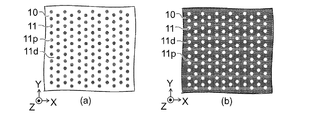
図8(a)〜図8(h)は、第1の実施形態に係る積層造形物の一部を例示する模式的平面図である。
これらの図は、第1部分10の凹凸11のパターン形状を例示している。
FIG. 8A to FIG. 8H are schematic plan views illustrating a part of the layered object according to the first embodiment.
These drawings illustrate the pattern shape of the
図8(a)に示した例では、複数の凸部11pが設けられる。凸部11pは、Y軸方向に延在する。複数の凸部11pは、X軸方向に並ぶ。この例では、凹部11dは、連続している。
In the example shown in FIG. 8A, a plurality of
図8(b)に示した例では、複数の凹部11dが設けられる。凹部11dは、Y軸方向に延在する。複数の凹部11dは、X軸方向に並ぶ。この例では、凸部11pは、連続している。
In the example shown in FIG. 8B, a plurality of
図8(c)に示した例では、凸部11pは、Y軸方向に延在する部分と、X軸方向に延在する部分と、を有する。凸部11pは、格子状である。この例では、複数の凹部11dが設けられる。
In the example shown in FIG. 8C, the
図8(d)に示した例では、凹部11dは、Y軸方向に延在する部分と、X軸方向に延在する部分と、を有する。凹部11dは、格子状である。この例では、複数の凸部11pが設けられる。
In the example shown in FIG. 8D, the
図8(e)に示した例では、複数の凸部11pが、Y軸方向と、X軸方向と、に沿って配置される。この例では、凹部11dは連続している。
In the example shown in FIG. 8E, the plurality of
図8(f)に示した例では、複数の凹部11dが、Y軸方向と、X軸方向と、に沿って配置される。この例では、凸部11pは連続している。
In the example shown in FIG. 8F, the plurality of
図8(g)に示した例では、連続した1つの凸部11pが、Y軸方向と、X軸方向と、に沿って、ジグザグ状に延びる。この例では、凹部11dは連続している。
In the example shown in FIG. 8G, one continuous
図8(h)に示した例では、連続した1つの凹部11dが、Y軸方向と、X軸方向と、に沿って、ジグザグ状に延びる。この例では、凸部11pは連続している。
In the example shown in FIG. 8H, one
図9は、第1の実施形態に係る積層造形物の一部を例示する模式的平面図である。
図9は、第1部分10の凹凸11のパターン形状を例示している。
FIG. 9 is a schematic plan view illustrating a part of the layered object according to the first embodiment.
FIG. 9 illustrates the pattern shape of the
図9(a)に示した例では、複数の凸部11pが設けられる。複数の凸部11pは、交互にピッチの1/2の距離でシフトしている。この例では、凹部11dは、連続している。
In the example shown in FIG. 9A, a plurality of
図9(b)に示した例では、複数の凹部11dが設けられる。複数の凹部11dは、交互にピッチの1/2の距離でシフトしている。この例では、凸部11pは、連続している。
このように、凹凸11は、第1方向(Z軸方向)に対して交差する第2方向に延在する凸部11p、及び、第2方向に延在する凹部11dの少なくともいずれかを含む。凹凸11は、複数の凸部11p、及び、複数の凹部11dの少なくともいずれかを含んでもよい。
In the example shown in FIG. 9B, a plurality of
As described above, the
実施形態において、凹凸11のパターンは、種々の変形が可能である。
In the embodiment, the pattern of the
(第2の実施形態)
本実施形態は、積層造形物の製造装置に係る。
図10は、第2の実施形態に係る積層造形物の製造装置を例示する模式的断面図である。
図10に表したように、本実施形態に係る積層造形物の製造装置210は、ステージ75と、ヘッド60と、凹凸部材70と、を含む。
(Second Embodiment)
The present embodiment relates to an apparatus for manufacturing a layered object.
FIG. 10 is a schematic cross-sectional view illustrating an apparatus for manufacturing a layered object according to the second embodiment.
As shown in FIG. 10, the layered
凹凸部材70は、ステージ75の上に設けられる。凹凸部材70の上面には、凹凸71が設けられている。
The
ヘッド60は、凹凸部材70に向けて、原料20mを供給しつつ原料20mを加熱して溶解させる。ヘッド60とステージ75との相対的な位置は変更可能である。例えば、ヘッド60とステージ75との相対的な位置は、Z軸方向、X軸方向及びY軸方向において、変更される。例えば、ヘッド60及びステージ75と接続された制御部77が設けられる。制御部77により、上記の動作が制御される。
The
例えば、凹凸71を有する凹凸部材70の上に、原料20mを用いて第1部分10が形成できる。第1部分10の凹凸11は、凹凸部材70の凹凸71を反映している。
For example, the
製造装置210によれば、凹凸部材70を用いることで、凹凸11を有する第1部分10を効率的に形成できる。そして、その第1部分10の上に第2部分20を形成することで、高強度の積層造形物が効率的に得られる。
According to the
実施形態において、距離検出部65をさらに設けても良い。距離検出部65は、例えば、ヘッド60と凹凸部材70との間の距離を検出する。距離検出部65は、例えば、ヘッド60と第1部分10との間の距離を検出する。検出された距離に基づいて、ヘッド60と凹凸部材70との距離、及び、ヘッド60と第1部分10との間の距離などが制御される。
In the embodiment, a distance detection unit 65 may be further provided. The distance detector 65 detects the distance between the
(第3の実施形態)
本実施形態は、積層造形物の製造方法に係る。
本製造方法においては。凹凸11を有する第1面10aを有する第1部分10の上に、複数の層(層21〜24など)を積層して、第1面10aに接する第2部分20を形成する。複数の層のそれぞれは、第2部分20の原料20mを供給しつつ、原料20mを加熱して溶解することで形成される。例えば、第2部分20は、第2面20aと、第3面20bと、を有する。第2面20aは、凹凸11と嵌合する。第3面20bは、第2面20bとは反対側の面である。第3面20bは、凹凸11よりも平坦な部分を含む。本製造方法によれば、高強度の積層造形物が効率的に得られる。
(Third embodiment)
The present embodiment relates to a method for manufacturing a layered object.
In this manufacturing method. A plurality of layers (such as the
実施形態によれば、高強度の積層造形物、その製造方法及び積層造形物の製造装置が提供できる。 According to the embodiment, a high-strength layered object, a manufacturing method thereof, and a manufacturing apparatus of the layered object can be provided.
なお、本願明細書において、「垂直」及び「平行」は、厳密な垂直及び厳密な平行だけではなく、例えば製造工程におけるばらつきなどを含むものであり、実質的に垂直及び実質的に平行であれば良い。 In the present specification, “vertical” and “parallel” include not only strictly vertical and strictly parallel, but also include, for example, variations in the manufacturing process, and may be substantially vertical and substantially parallel. It ’s fine.
以上、具体例を参照しつつ、本発明の実施の形態について説明した。しかし、本発明は、これらの具体例に限定されるものではない。例えば、積層造形物に含まれる第1部分及び第2部分、並びに、製造装置に含まれるヘッド、ステージ及び凹凸部材などの各要素の具体的な構成に関しては、当業者が公知の範囲から適宜選択することにより本発明を同様に実施し、同様の効果を得ることができる限り、本発明の範囲に包含される。 The embodiments of the present invention have been described above with reference to specific examples. However, the present invention is not limited to these specific examples. For example, the specific configuration of each element such as the first and second parts included in the layered object and the head, stage, and concavo-convex member included in the manufacturing apparatus is appropriately selected by those skilled in the art from a known range. By doing so, the present invention is included in the scope of the present invention as long as the same effects can be obtained and similar effects can be obtained.
また、各具体例のいずれか2つ以上の要素を技術的に可能な範囲で組み合わせたものも、本発明の要旨を包含する限り本発明の範囲に含まれる。 Moreover, what combined any two or more elements of each specific example in the technically possible range is also included in the scope of the present invention as long as the gist of the present invention is included.
その他、本発明の実施の形態として上述した積層造形物、その製造方法及び積層造形物の製造装置を基にして、当業者が適宜設計変更して実施し得る全ての積層造形物、その製造方法及び積層造形物の製造装置も、本発明の要旨を包含する限り、本発明の範囲に属する。 In addition, based on the layered object described above as an embodiment of the present invention, the manufacturing method thereof, and the apparatus for manufacturing the layered object, all the layered objects that can be appropriately modified by a person skilled in the art and the manufacturing method thereof And the manufacturing apparatus of a layered object also belongs to the scope of the present invention as long as it includes the gist of the present invention.
その他、本発明の思想の範疇において、当業者であれば、各種の変更例及び修正例に想到し得るものであり、それら変更例及び修正例についても本発明の範囲に属するものと了解される。 In addition, in the category of the idea of the present invention, those skilled in the art can conceive of various changes and modifications, and it is understood that these changes and modifications also belong to the scope of the present invention. .
本発明のいくつかの実施形態を説明したが、これらの実施形態は、例として提示したものであり、発明の範囲を限定することは意図していない。これら新規な実施形態は、その他の様々な形態で実施されることが可能であり、発明の要旨を逸脱しない範囲で、種々の省略、置き換え、変更を行うことができる。これら実施形態やその変形は、発明の範囲や要旨に含まれるとともに、特許請求の範囲に記載された発明とその均等の範囲に含まれる。 Although several embodiments of the present invention have been described, these embodiments are presented by way of example and are not intended to limit the scope of the invention. These novel embodiments can be implemented in various other forms, and various omissions, replacements, and changes can be made without departing from the scope of the invention. These embodiments and modifications thereof are included in the scope and gist of the invention, and are included in the invention described in the claims and the equivalents thereof.
10…第1部分、 10a…第1面、 11…凹凸、 11d…凹部、 11dw…幅、 11p…凸部、 11pp…ピッチ、 11pw…幅、 11t…高さ、 20…第2部分、 20a…第2面、 20b…第3面、 20m…原料、 21〜24…層、 27…凹凸、 27d…凹部、 21p…凸部、 50…基体、 60…ヘッド、 61…エネルギー線、 62…シールドガス、 65…距離検出部、 68…溶解領域、 70…凹凸部材、 71…凹凸、 75…ステージ、 110、111、112…積層造形物、 210…製造装置
DESCRIPTION OF
Claims (7)
凹凸が設けられた凹凸部材に向けて、原料を供給しつつ前記原料を加熱して溶解させ、前記凹凸部材との相対的な位置を変更可能なヘッドと、
を備えた積層造形物の製造装置。 A layered object modeled by a plurality of stacked layers, a first part having a first surface having irregularities and a part of the plurality of layers, and a second part in contact with the first surface A second surface along the concave-convex shape, a third surface opposite to the second surface, and a second portion including another part of the plurality of layers, The third surface is an apparatus for manufacturing a layered object including a portion flatter than the unevenness,
Irregularities toward the uneven member provided, the raw material heated to dissolve the raw material while supplying, capable of changing the relative position between the concavo-convex member head,
The manufacturing apparatus of the layered product provided with.
前記凹凸を有する前記第1面を有する前記第1部分の上に、前記第1面に接する第2部分を積層し、
前記第2部分は前記第2部分の原料を供給しつつ前記原料を加熱して溶解することで形成される積層造形物の製造方法。 A layered object modeled by a plurality of stacked layers, a first part having a first surface having irregularities and a part of the plurality of layers, and a second part in contact with the first surface A second surface along the concave-convex shape, a third surface opposite to the second surface, and a second portion including another part of the plurality of layers, The third surface is a manufacturing method of a layered object including a portion flatter than the unevenness,
On the first portion having a first surface having the irregularities, stacking a second portion in contact with the front Symbol first surface,
Said second portion method of manufacturing a multilayer molded article which is formed by dissolving and heating the raw material supplying the feedstock of the second portion.
前記複数の凸部の少なくとも一部において、前記複数の凸部のそれぞれの幅が一定である請求項2または3に記載の積層造形物の製造方法。 The unevenness has a plurality of convex portions arranged in a second direction intersecting the first direction in a first cut surface including a first direction from the first portion toward the second portion,
The method for manufacturing a layered object according to claim 2 or 3 , wherein a width of each of the plurality of protrusions is constant in at least a part of the plurality of protrusions .
前記複数の凹部の少なくとも一部において、前記複数の凹部のそれぞれの幅が一定である請求項2または3に記載の積層造形物の製造方法。 The method for manufacturing a layered object according to claim 2 or 3, wherein a width of each of the plurality of recesses is constant in at least a part of the plurality of recesses.
前記第1部分から前記第2部分に向かう第1方向に対して交差する第2方向に延在する凸部、及び、
前記第2方向に延在する凹部、
の少なくともいずれかを含む請求項2〜5のいずれか1つに記載の積層造形物の製造方法。 The unevenness is
A convex portion extending in a second direction intersecting the first direction from the first portion toward the second portion; and
A recess extending in the second direction,
The method for producing a layered object according to any one of claims 2 to 5 , comprising at least one of the following .
Priority Applications (3)
| Application Number | Priority Date | Filing Date | Title |
|---|---|---|---|
| JP2014054420A JP5981475B2 (en) | 2014-03-18 | 2014-03-18 | Laminated shaped article manufacturing apparatus and laminated shaped article manufacturing method |
| PCT/JP2014/073341 WO2015141027A1 (en) | 2014-03-18 | 2014-09-04 | Laminated molded body, laminated molded body manufacturing method, and laminated molded body manufacturing apparatus |
| US15/023,887 US10040251B2 (en) | 2014-03-18 | 2014-09-04 | Layered object, method for manufacturing layered object, and apparatus for manufacturing layered object |
Applications Claiming Priority (1)
| Application Number | Priority Date | Filing Date | Title |
|---|---|---|---|
| JP2014054420A JP5981475B2 (en) | 2014-03-18 | 2014-03-18 | Laminated shaped article manufacturing apparatus and laminated shaped article manufacturing method |
Publications (2)
| Publication Number | Publication Date |
|---|---|
| JP2015174421A JP2015174421A (en) | 2015-10-05 |
| JP5981475B2 true JP5981475B2 (en) | 2016-08-31 |
Family
ID=54144025
Family Applications (1)
| Application Number | Title | Priority Date | Filing Date |
|---|---|---|---|
| JP2014054420A Active JP5981475B2 (en) | 2014-03-18 | 2014-03-18 | Laminated shaped article manufacturing apparatus and laminated shaped article manufacturing method |
Country Status (3)
| Country | Link |
|---|---|
| US (1) | US10040251B2 (en) |
| JP (1) | JP5981475B2 (en) |
| WO (1) | WO2015141027A1 (en) |
Families Citing this family (4)
| Publication number | Priority date | Publication date | Assignee | Title |
|---|---|---|---|---|
| WO2016083181A1 (en) * | 2014-11-27 | 2016-06-02 | Philips Lighting Holding B.V. | Printing head, printing apparatus, printing method and printed article |
| US10780654B2 (en) * | 2017-04-25 | 2020-09-22 | Signify Holding B.V. | Imprinted 3D printed structure, printing method, 3D item and lighting system therewith |
| JP7309544B2 (en) * | 2019-09-13 | 2023-07-18 | 株式会社東芝 | Coating method and coating structure |
| CN112077312B (en) * | 2020-09-27 | 2022-01-28 | 江苏科技大学 | Preparation method of copper-aluminum transition section composite structure |
Family Cites Families (10)
| Publication number | Priority date | Publication date | Assignee | Title |
|---|---|---|---|---|
| JPH09115191A (en) * | 1995-10-13 | 1997-05-02 | Victor Co Of Japan Ltd | Optical information recording medium and its production |
| TW506868B (en) | 2000-10-05 | 2002-10-21 | Matsushita Electric Works Ltd | Method of and apparatus for making a three-dimensional object |
| JP3491627B2 (en) * | 2001-06-26 | 2004-01-26 | 松下電工株式会社 | Manufacturing method of three-dimensional shaped object |
| JP2006200030A (en) | 2005-01-24 | 2006-08-03 | Aisan Ind Co Ltd | Method and device for producing cubic molding |
| JP4452692B2 (en) * | 2006-02-03 | 2010-04-21 | 株式会社松浦機械製作所 | Surface finishing method for 3D additive manufacturing parts |
| JP5152070B2 (en) * | 2009-03-31 | 2013-02-27 | 大日本印刷株式会社 | Decorative sheet, decorative molded product, and injection molding simultaneous decoration method |
| US9056354B2 (en) * | 2011-08-30 | 2015-06-16 | Siemens Aktiengesellschaft | Material system of co-sintered metal and ceramic layers |
| US8999226B2 (en) * | 2011-08-30 | 2015-04-07 | Siemens Energy, Inc. | Method of forming a thermal barrier coating system with engineered surface roughness |
| JP2013075392A (en) * | 2011-09-29 | 2013-04-25 | Brother Industries Ltd | Three dimensional molding apparatus, three dimensional molding method, and three dimensional molding data creating program |
| JP5690752B2 (en) * | 2012-01-10 | 2015-03-25 | 日立オートモティブシステムズ株式会社 | Power semiconductor module and method of manufacturing power semiconductor module |
-
2014
- 2014-03-18 JP JP2014054420A patent/JP5981475B2/en active Active
- 2014-09-04 WO PCT/JP2014/073341 patent/WO2015141027A1/en active Application Filing
- 2014-09-04 US US15/023,887 patent/US10040251B2/en active Active
Also Published As
| Publication number | Publication date |
|---|---|
| US20160375637A1 (en) | 2016-12-29 |
| JP2015174421A (en) | 2015-10-05 |
| US10040251B2 (en) | 2018-08-07 |
| WO2015141027A1 (en) | 2015-09-24 |
Similar Documents
| Publication | Publication Date | Title |
|---|---|---|
| JP5981475B2 (en) | Laminated shaped article manufacturing apparatus and laminated shaped article manufacturing method | |
| JP5162977B2 (en) | Laser drilling method | |
| JP6453847B2 (en) | Storage tool with three-dimensional projections | |
| JP6897279B2 (en) | Stage for 3D modeling | |
| CN103722171B (en) | A kind of honeycomb fashion laser scanning method for selective laser sintering | |
| JP6452490B2 (en) | Semiconductor chip generation method | |
| JP5932700B2 (en) | Method for producing composite molded body | |
| JP6170238B1 (en) | Control method for three-dimensional additive manufacturing apparatus, control method for three-dimensional additive manufacturing apparatus, and control program for three-dimensional additive manufacturing apparatus | |
| JP2016225598A5 (en) | ||
| JP2014065288A (en) | Composite molding and production method of the same | |
| JP6132186B2 (en) | Manufacturing method and apparatus for preform manufacturing base material, and manufacturing method of preform and fiber reinforced plastic | |
| JP2017002408A5 (en) | ||
| RU2015125712A (en) | METHOD FOR PRODUCING DETAILS OF POWDER MELTING, PARTICLES OF WHICH ACHIEVE A LIQUID BATH IN A COLD STATE | |
| JP6432230B2 (en) | Modeling apparatus, method for manufacturing modeled object, and application unit | |
| US20150142160A1 (en) | Three-dimensional modeling method | |
| JP2015512112A (en) | Bridge structure in a conductive mesh and method for manufacturing the same | |
| JP6870028B2 (en) | Method of additionally manufacturing at least one three-dimensional object | |
| JP2013092758A5 (en) | ||
| WO2005121846A1 (en) | Light diffraction structure transfer sheet and method for producing the same | |
| KR102012236B1 (en) | Method of manufacturing three dimensional shapes using laser and metal powder | |
| JP2013125855A5 (en) | ||
| JP7249127B2 (en) | Slanted structure and manufacturing method thereof | |
| CN103692091A (en) | Surface plate laser stitch welding technology | |
| JP2020047393A5 (en) | ||
| JP2017109383A (en) | Composite molding member, method for producing composite molding member, and electronic component |
Legal Events
| Date | Code | Title | Description |
|---|---|---|---|
| RD02 | Notification of acceptance of power of attorney |
Free format text: JAPANESE INTERMEDIATE CODE: A7422 Effective date: 20151002 |
|
| A521 | Request for written amendment filed |
Free format text: JAPANESE INTERMEDIATE CODE: A821 Effective date: 20151002 |
|
| RD04 | Notification of resignation of power of attorney |
Free format text: JAPANESE INTERMEDIATE CODE: A7424 Effective date: 20151124 |
|
| A131 | Notification of reasons for refusal |
Free format text: JAPANESE INTERMEDIATE CODE: A131 Effective date: 20160315 |
|
| A521 | Request for written amendment filed |
Free format text: JAPANESE INTERMEDIATE CODE: A523 Effective date: 20160428 |
|
| TRDD | Decision of grant or rejection written | ||
| A01 | Written decision to grant a patent or to grant a registration (utility model) |
Free format text: JAPANESE INTERMEDIATE CODE: A01 Effective date: 20160628 |
|
| A61 | First payment of annual fees (during grant procedure) |
Free format text: JAPANESE INTERMEDIATE CODE: A61 Effective date: 20160728 |
|
| R151 | Written notification of patent or utility model registration |
Ref document number: 5981475 Country of ref document: JP Free format text: JAPANESE INTERMEDIATE CODE: R151 |