JP5980511B2 - Secondary battery and manufacturing method thereof - Google Patents
Secondary battery and manufacturing method thereof Download PDFInfo
- Publication number
- JP5980511B2 JP5980511B2 JP2012006780A JP2012006780A JP5980511B2 JP 5980511 B2 JP5980511 B2 JP 5980511B2 JP 2012006780 A JP2012006780 A JP 2012006780A JP 2012006780 A JP2012006780 A JP 2012006780A JP 5980511 B2 JP5980511 B2 JP 5980511B2
- Authority
- JP
- Japan
- Prior art keywords
- terminal
- fastening
- battery
- secondary battery
- cap plate
- Prior art date
- Legal status (The legal status is an assumption and is not a legal conclusion. Google has not performed a legal analysis and makes no representation as to the accuracy of the status listed.)
- Active
Links
Images


Classifications
-
- H—ELECTRICITY
- H01—ELECTRIC ELEMENTS
- H01M—PROCESSES OR MEANS, e.g. BATTERIES, FOR THE DIRECT CONVERSION OF CHEMICAL ENERGY INTO ELECTRICAL ENERGY
- H01M50/00—Constructional details or processes of manufacture of the non-active parts of electrochemical cells other than fuel cells, e.g. hybrid cells
- H01M50/10—Primary casings, jackets or wrappings of a single cell or a single battery
- H01M50/147—Lids or covers
-
- H—ELECTRICITY
- H01—ELECTRIC ELEMENTS
- H01M—PROCESSES OR MEANS, e.g. BATTERIES, FOR THE DIRECT CONVERSION OF CHEMICAL ENERGY INTO ELECTRICAL ENERGY
- H01M50/00—Constructional details or processes of manufacture of the non-active parts of electrochemical cells other than fuel cells, e.g. hybrid cells
- H01M50/10—Primary casings, jackets or wrappings of a single cell or a single battery
- H01M50/172—Arrangements of electric connectors penetrating the casing
- H01M50/174—Arrangements of electric connectors penetrating the casing adapted for the shape of the cells
- H01M50/176—Arrangements of electric connectors penetrating the casing adapted for the shape of the cells for prismatic or rectangular cells
-
- H—ELECTRICITY
- H01—ELECTRIC ELEMENTS
- H01M—PROCESSES OR MEANS, e.g. BATTERIES, FOR THE DIRECT CONVERSION OF CHEMICAL ENERGY INTO ELECTRICAL ENERGY
- H01M50/00—Constructional details or processes of manufacture of the non-active parts of electrochemical cells other than fuel cells, e.g. hybrid cells
- H01M50/30—Arrangements for facilitating escape of gases
- H01M50/342—Non-re-sealable arrangements
- H01M50/3425—Non-re-sealable arrangements in the form of rupturable membranes or weakened parts, e.g. pierced with the aid of a sharp member
-
- H—ELECTRICITY
- H01—ELECTRIC ELEMENTS
- H01M—PROCESSES OR MEANS, e.g. BATTERIES, FOR THE DIRECT CONVERSION OF CHEMICAL ENERGY INTO ELECTRICAL ENERGY
- H01M50/00—Constructional details or processes of manufacture of the non-active parts of electrochemical cells other than fuel cells, e.g. hybrid cells
- H01M50/50—Current conducting connections for cells or batteries
- H01M50/502—Interconnectors for connecting terminals of adjacent batteries; Interconnectors for connecting cells outside a battery casing
- H01M50/514—Methods for interconnecting adjacent batteries or cells
- H01M50/517—Methods for interconnecting adjacent batteries or cells by fixing means, e.g. screws, rivets or bolts
-
- H—ELECTRICITY
- H01—ELECTRIC ELEMENTS
- H01M—PROCESSES OR MEANS, e.g. BATTERIES, FOR THE DIRECT CONVERSION OF CHEMICAL ENERGY INTO ELECTRICAL ENERGY
- H01M50/00—Constructional details or processes of manufacture of the non-active parts of electrochemical cells other than fuel cells, e.g. hybrid cells
- H01M50/50—Current conducting connections for cells or batteries
- H01M50/531—Electrode connections inside a battery casing
-
- H—ELECTRICITY
- H01—ELECTRIC ELEMENTS
- H01M—PROCESSES OR MEANS, e.g. BATTERIES, FOR THE DIRECT CONVERSION OF CHEMICAL ENERGY INTO ELECTRICAL ENERGY
- H01M50/00—Constructional details or processes of manufacture of the non-active parts of electrochemical cells other than fuel cells, e.g. hybrid cells
- H01M50/50—Current conducting connections for cells or batteries
- H01M50/543—Terminals
- H01M50/547—Terminals characterised by the disposition of the terminals on the cells
- H01M50/55—Terminals characterised by the disposition of the terminals on the cells on the same side of the cell
-
- H—ELECTRICITY
- H01—ELECTRIC ELEMENTS
- H01M—PROCESSES OR MEANS, e.g. BATTERIES, FOR THE DIRECT CONVERSION OF CHEMICAL ENERGY INTO ELECTRICAL ENERGY
- H01M50/00—Constructional details or processes of manufacture of the non-active parts of electrochemical cells other than fuel cells, e.g. hybrid cells
- H01M50/50—Current conducting connections for cells or batteries
- H01M50/543—Terminals
- H01M50/552—Terminals characterised by their shape
- H01M50/553—Terminals adapted for prismatic, pouch or rectangular cells
-
- H—ELECTRICITY
- H01—ELECTRIC ELEMENTS
- H01M—PROCESSES OR MEANS, e.g. BATTERIES, FOR THE DIRECT CONVERSION OF CHEMICAL ENERGY INTO ELECTRICAL ENERGY
- H01M50/00—Constructional details or processes of manufacture of the non-active parts of electrochemical cells other than fuel cells, e.g. hybrid cells
- H01M50/50—Current conducting connections for cells or batteries
- H01M50/543—Terminals
- H01M50/564—Terminals characterised by their manufacturing process
- H01M50/567—Terminals characterised by their manufacturing process by fixing means, e.g. screws, rivets or bolts
-
- Y—GENERAL TAGGING OF NEW TECHNOLOGICAL DEVELOPMENTS; GENERAL TAGGING OF CROSS-SECTIONAL TECHNOLOGIES SPANNING OVER SEVERAL SECTIONS OF THE IPC; TECHNICAL SUBJECTS COVERED BY FORMER USPC CROSS-REFERENCE ART COLLECTIONS [XRACs] AND DIGESTS
- Y02—TECHNOLOGIES OR APPLICATIONS FOR MITIGATION OR ADAPTATION AGAINST CLIMATE CHANGE
- Y02E—REDUCTION OF GREENHOUSE GAS [GHG] EMISSIONS, RELATED TO ENERGY GENERATION, TRANSMISSION OR DISTRIBUTION
- Y02E60/00—Enabling technologies; Technologies with a potential or indirect contribution to GHG emissions mitigation
- Y02E60/10—Energy storage using batteries
-
- Y—GENERAL TAGGING OF NEW TECHNOLOGICAL DEVELOPMENTS; GENERAL TAGGING OF CROSS-SECTIONAL TECHNOLOGIES SPANNING OVER SEVERAL SECTIONS OF THE IPC; TECHNICAL SUBJECTS COVERED BY FORMER USPC CROSS-REFERENCE ART COLLECTIONS [XRACs] AND DIGESTS
- Y02—TECHNOLOGIES OR APPLICATIONS FOR MITIGATION OR ADAPTATION AGAINST CLIMATE CHANGE
- Y02P—CLIMATE CHANGE MITIGATION TECHNOLOGIES IN THE PRODUCTION OR PROCESSING OF GOODS
- Y02P70/00—Climate change mitigation technologies in the production process for final industrial or consumer products
- Y02P70/50—Manufacturing or production processes characterised by the final manufactured product
Description
本発明は、2次電池及びその製造方法に関する。 The present invention relates to a secondary battery and a manufacturing method thereof.
2次電池(Rechargeable battery)は、充電が不可能な一次電池とは違って充電及び放電が可能な電池である。これに関し、一つのバッテリーセルがパック形態に包装された低容量電池の場合、携帯電話及びカムコーダのような携帯が可能な小型電子機器に使用される。また、バッテリーセルが数十個連結された大容量電池の場合、電気スクーター、ハイブリッド自動車及び電気自動車などのモータ駆動用電源として幅広く使用されている。 A rechargeable battery is a battery that can be charged and discharged unlike a primary battery that cannot be charged. In this regard, in the case of a low-capacity battery in which one battery cell is packaged in a pack form, it is used for portable electronic devices such as mobile phones and camcorders. Further, in the case of a large-capacity battery in which several tens of battery cells are connected, it is widely used as a motor driving power source for electric scooters, hybrid vehicles, electric vehicles and the like.
2次電池は様々な形状に製造されているが、代表的な形状としては、円筒形及び角形が挙げられ、正、負極板の間に絶縁体であるセパレータを介在して形成された電極組立体及び電解液を共にケースに収容し、ケースにキャッププレートを設けている。もちろん、前記電極組立体には正極端子及び負極端子が連結され、これは前記キャッププレートを通して外部に露出及び突出する。なお、2次電池の形状に関しては、例えば、下記の特許文献1に記載がある。 Although secondary batteries are manufactured in various shapes, typical shapes include a cylindrical shape and a rectangular shape, and an electrode assembly formed by interposing a separator as an insulator between positive and negative electrodes, and Both electrolytic solutions are accommodated in a case, and a cap plate is provided on the case. Of course, a positive electrode terminal and a negative electrode terminal are connected to the electrode assembly, which are exposed and protruded to the outside through the cap plate. The shape of the secondary battery is described in, for example, Patent Document 1 below.
本発明の目的は、2次電池の連結のために必要な部品数を減少させることができ、2次電池の製造工程を単純化させることができる2次電池を提供することにある。 An object of the present invention is to provide a secondary battery that can reduce the number of components required for connecting the secondary batteries and can simplify the manufacturing process of the secondary batteries.
また、第1締結端子及び第2締結端子とバスバーとの結合力を高めることができる2次電池を提供できるようにすることがより好ましい。さらに、2次電池間又は2次電池と外部電子機器との間の電気的信頼性を高めることができる2次電池を提供できるようにすることがより好ましい。 Moreover, it is more preferable to provide a secondary battery that can increase the coupling force between the first fastening terminal and the second fastening terminal and the bus bar. Furthermore, it is more preferable to provide a secondary battery that can increase the electrical reliability between the secondary batteries or between the secondary battery and the external electronic device.
上記課題を解決するために、本発明のある観点によれば、2次電池であって、電極組立体、前記電極組立体と電気的に連結される端子、前記電極組立体と端子とを収容するケース、及び前記ケースを密封するキャッププレートを含むキャップ組立体を含み、前記端子は前記電極組立体と連結される集電板、前記集電板と連結され、前記キャッププレートを貫通する集電端子、及び集電端子用ホールとねじ山とを有し、前記集電端子用ホールを通して前記集電端子と結合する締結端子を含む2次電池が提供される。 In order to solve the above problems, according to an aspect of the present invention, a secondary battery includes an electrode assembly, a terminal electrically connected to the electrode assembly, and the electrode assembly and the terminal. And a cap assembly including a cap plate for sealing the case, and the terminal is connected to the electrode assembly, and the current collector is connected to the current collector and passes through the cap plate. There is provided a secondary battery including a terminal and a fastening terminal having a current collecting terminal hole and a thread and coupled to the current collecting terminal through the current collecting terminal hole.
以上説明したように本発明によれば、2次電池の連結のために必要な部品数を減少させることができ、2次電池の製造工程を単純化させることができる。 As described above, according to the present invention, it is possible to reduce the number of parts required for connecting the secondary batteries, and to simplify the manufacturing process of the secondary batteries.
以下に添付図面を参照しながら、本発明の好適な実施の形態について詳細に説明する。なお、本明細書及び図面において、実質的に同一の機能構成を有する構成要素については、同一の符号を付することにより重複説明を省略する。 Exemplary embodiments of the present invention will be described below in detail with reference to the accompanying drawings. In addition, in this specification and drawing, about the component which has the substantially same function structure, duplication description is abbreviate | omitted by attaching | subjecting the same code | symbol.
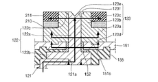
図1は、本発明の一実施例による2次電池を示す斜視図であり、図2は、図1のI-I’線に沿って切断した2次電池を示す断面図であり、図3は、図2に示されたA部分の拡大断面図であり、図4は、図2に示されたB部分の拡大断面図である。 FIG. 1 is a perspective view illustrating a secondary battery according to an embodiment of the present invention, and FIG. 2 is a cross-sectional view illustrating the secondary battery cut along the line II ′ of FIG. FIG. 4 is an enlarged sectional view of a portion A shown in FIG. 2, and FIG. 4 is an enlarged sectional view of a portion B shown in FIG.
図1〜図4に示すように、本発明の一実施例による2次電池100は、電極組立体110、第1端子120、第2端子130、ケース140及びキャップ組立体150を含む。
1 to 4, the
前記電極組立体110は、薄い板型又は膜型の第1電極板111、セパレータ113、第2電極板112が成す積層体を巻き取るか重なるように形成される。ここで、第1電極板111は、正極として動作することができる。一方、第2電極板112は、負極として動作することができる。もちろん、その逆の場合も可能である。
The
前記第1電極板111は、アルミニウムのような金属箔からなる第1電極集電体に遷移金属酸化物などの第1電極活物質を塗布することによって形成され、第1活物質が塗布されない領域である第1電極無地部111aを含む。前記第1電極無地部111aは、第1電極板111と第1電極板外部との間の電流の流れ通路になる。また、前記第1電極板111の材質はこれに限定されるものではない。
The
前記第2電極板112は、銅又はニッケルのような金属箔からなる第2電極集電体に黒鉛又は炭素などの第2電極活物質を塗布することによって形成され、第2活物質が塗布されない領域である第2電極無地部112aを含む。前記第2電極無地部112aは、第2電極板112と第2電極板外部との間の電流の流れ通路になる。また、前記第2電極板112の材質はこれに限定されるものではない。
The
前記のような第1電極板111及び第2電極板112は極性を異にして配置されることができる。
The
前記セパレータ113は、第1電極板111と第2電極板112との間に位置して短絡を防止し、リチウムイオンの移動を可能にする役割を果たし、ポリエチレンやポリプロピレンやポリエチレンとポリプロピレンとの複合フイルムからなることができる。また、前記セパレータ113の材質はこれに限定されるものではない。
The
このような電極組立体110は、実質的に電解液と共にケース140に収納される。前記電解液は、EC(ethylene carbonate)、PC(propylene carbonate)、DEC(diethyl carbonate)、EMC(ethyl methyl carbonate)、DMC(dimethyl carbonate)のような有機溶媒にLiPF6、LiBF4を溶かしたリチウム塩からなることができる。また、前記電解液は液体、固体又はゲル状であることができる。
Such an
前記のような電極組立体110の両側端部には第1電極板111と第2電極板112のそれぞれに電気的に連結される第1端子120及び第2端子130が結合する。
The
前記第1端子120は、主に金属又はその等価物からなり、第1電極板111と電気的に連結される。前記第1端子120は、第1集電板121、第1集電端子122及び第1締結端子123を含む。
The
前記第1集電板121は、電極組立体110の一側端部に突出した第1電極無地部111aと接触される。実質的に、前記第1集電板121は、第1電極無地部111aに溶接される。前記第1集電板121は、ほぼL字形状(例えば、図2に示すように、上方に延伸して右方向に略直角に折れ曲がる形状)に形成され、上部に形成される第1端子ホール121aを有する。前記第1端子ホール121aには、第1集電端子122が嵌合されて結合する。このような第1集電板121は、アルミニウム、アルミニウム合金及びその等価物のうち選択されるいずれか一つの材質で形成されることができるが、これに限定されるものではない。
The first
前記第1集電端子122は、キャッププレート151を貫通して上部に一定の長さが突出及び延長され、また、キャッププレート151の下部で第1集電板121と電気的に連結される。このような第1集電端子122は、例えば、アルミニウム、アルミニウム合金及びその等価物のうち選択されるいずれか一つの材質で形成されることができるが、これに限定されるものではない。前記第1集電端子122は、第1ボディー部122a、第1フランジ部122b及び第1固定部122cを含む。
The first current collecting
前記第1ボディー部122aは、キャッププレート151の上部に突出する上部柱と、上部柱の下部に連結され、キャッププレート151の下部にまで延長される下部柱とに区分される。ここで、前記第1ボディー部122aは円柱形状であることができるが、これに限定されるものではない。
The
前記第1フランジ部122bは、第1ボディー部122aの下部柱の側部から略水平方向に延長されるように形成される。例えば、図3に示すように、第1フランジ部122bは、第1ボディー部122aの延伸方向と略直交する方向に延伸して形成される。このような第1フランジ部122bは、第1集電端子122がキャッププレート151から離脱しないように作用する。例えば、第1ボディー部122aの長手方向に力が加わっても、第1フランジ部122bが上部又は下部に当接する部材にひっかかるため、第1集電端子122がキャッププレート151から離脱することを防止できる。なお、前記第1ボディー部122aの下部柱の中、第1フランジ部122bの下部に連結された部分は第1集電板121の第1端子ホール121aに嵌合されて溶接される。
The
前記第1固定部122cは、第1集電端子122の上部柱の側端部から略水平方向に延長されるように形成される。このような第1固定部122cは、第1集電端子122を第1締結端子123に固定されるようにする。例えば、図3に示すように、第1締結端子123には、第1固定部122cが嵌合するように形成された溝(後述する第1固定溝123f)が設けられており、この溝に第1固定部122cが引っ掛かることで第1集電端子122が固定される。ここで、前記第1固定部122cは、第1集電端子122の上部柱の端部をリベッティングすることによって形成されることができる。
The
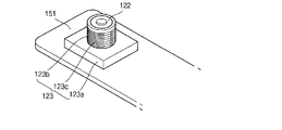
前記第1締結端子123は、キャッププレート151の上部に配置され、第1集電端子122の上部柱が貫通して結合するように形成され、ほぼボルト形状である。このような第1締結端子123は、第1集電端子122及びキャッププレート151との間で電気的、機械的に連結される。前記第1締結端子123は、アルミニウム、アルミニウム合金及びその等価物のうち選択されるいずれか一つの材質で形成されることができるが、これに限定されるものではない。前記第1締結端子123は、より詳しくは、第1ベース部123a、第1延長部123b、第1ねじ山123c、第1回転防止突起123d、第1集電端子用ホール123e及び第1固定溝123fを含む。
The
前記第1ベース部123aは、キャッププレート151と接触する部分であり、第1締結端子123をキャッププレート151に安定的に安着させ、第1締結端子123とキャッププレート151との接触面積を高めるため、第1締結端子123のうち、最も大きい面積を有する。ここで、前記第1ベース部123aは四角柱状であることができるが、これに限定されるものではない。
The
前記第1延長部123bは、第1ベース部123aから上部方向に延長され、第1ベース部123aより小さい面積を有する。ここで、前記第1延長部123bと第1ベース部123aとの面積差によって発生した空間には、バスバー(図6の符号210)を第1締結端子123に結合させるためのナット(図6の符号211)が配置されることができる。また、前記第1延長部123bは円柱状に形成されることができるが、これに限定されるものではない。
The
前記第1ねじ山123cは、第1延長部123bの外面に形成され、ナット(図6の符号211)が第1締結端子123に締結されるようにガイドする。
The
前記第1回転防止突起123dは、第1ベース部123aの下面に形成され、キャッププレート151の回転防止溝151cに結合する。このような第1回転防止突起123dは、ナット(図6の符号211)の第1締結端子123に締結の際、第1締結端子123の回転を防止する役割を果たす。
The first
前記第1集電端子用ホール123eは、第1ベース部123a及び第1延長部123bに形成され、第1集電端子122の上部柱が通過する空間を提供する。
The first current collecting
前記第1固定溝123fは、第1延長部123bの上端部に第1集電端子用ホール123eの直径より大きい直径を有するように形成され、第1固定部122cがかけられて固定される空間を提供する。
The
前記のように構成される第1締結端子123は、第1集電端子122だけでなく、バスバー(図6の符号210)を第1締結端子123に結合させるためのナット(図6の符号211)と電気的、機械的に締結される。これによって、前記第1締結端子123は、2次電池の連結のための部品数を減少させることができ、2次電池の製造工程を単純化することができる。
The
また、前記第1締結端子123は、第1回転防止突起123dを通じてキャッププレート151に結合する。これによって、バスバー(図6の符号210)を第1締結端子123に結合させるためのナット(図6の符号211)が第1集電端子122に影響を与えずに強いトルクで第1締結端子123に締結されるので、バスバー(図6の符号210)の結合力が高まることになる。
The
また、前記第1締結端子123は、第1ベース部123a及び第1延長部123bを通じて第1集電端子122、キャッププレート151及びナット(図6の符号211)間の広い接触面積を確保することによって、2次電池間又は2次電池と外部電子機器との間の電気的信頼性を高めることができる。
Further, the
前記第2端子130は、第1端子120と同様に、主に金属又はその等価物からなり、第2電極板112と電気的に連結される。前記第2端子130は、第2集電板131、第2集電端子132及び第2締結端子133を含む。
Similar to the
前記第2集電板131は、電極組立体110の他側端部に突出した第2電極無地部112aと接触される。実質的に、前記第2集電板131は、第2電極無地部112aに溶接される。前記第2集電板131は、ほぼL字形状(図2に示すように、上方に延伸して略直角に左方向へと折れ曲がる形状)に形成され、上部に形成される第2端子ホール131aを有する。前記第2端子ホール131aには、第2集電端子132が嵌合されて結合する。このような第2集電板131は、例えば、銅、銅合金及びその等価物のうち選択されるいずれか一つの材質で形成されることができるが、これに限定されるものではない。
The second current collecting
前記第2集電端子132は、キャッププレート151を貫通して上部に一定の長さに突出及び延長され、キャッププレート151の下部で第2集電板131と電気的に連結される。このような第2集電端子132は、例えば銅、銅合金及びその等価物のうち選択されるいずれか一つの材質で形成されることができるが、これに限定されるものではない。前記第2集電端子132は、より詳しくは、第2ボディー部132a、第2フランジ部132b及び第2固定部132cを含む。
The second current collecting terminal 132 protrudes and extends through the
前記第2ボディー部132aは、上部柱と下部柱とに区分され、第1ボディー部122aと同様であるので、詳しい説明は省略する。
The
前記第2フランジ部133bは、第1フランジ部122bと同様であるので、詳しい説明は省略する。一方、第2ボディー部132aの下部柱の中、第2フランジ部132bの下部に連結される部分は、第2集電板131の第2端子ホール131aに嵌合されて溶接される。
Since the
前記第2固定部132cは、第1固定部122cと同様であるので、詳しい説明は省略する。
Since the
前記第2締結端子133は、キャッププレート151の上部、より詳しくは、上部絶縁部材157の上面に配置され、第2集電端子132の上部柱が貫通して結合できるように形成され、ほぼボルト形状である。このような第2締結端子133は、第2集電端子132と電気的に連結され、上部絶縁部材157を通じてキャッププレート151と電気的に絶縁される。前記第2締結端子133は、銅、銅合金及びその等価物のうち選択されるいずれか一つの材質で形成されることができる。前記第2締結端子133は、より詳しくは、第2ベース部133a、第2延長部133b、第2ねじ山133c、第2回転防止溝133d、第2集電端子用ホール133e、第2固定溝133f及び第2結合溝133gを含む。
The
前記第2ベース部133aは、上部絶縁部材157と接触する部分であり、第2締結端子133を上部絶縁部材157に安定的に安着させるために第2締結端子133の中、最も大きい面積を有する。ここで、前記第2ベース部133aは、略四角柱状であることができるが、これに限定されるものではない。一方、前記第2ベース部133aがキャッププレート151ではなく、上部絶縁部材157と接触する理由は、第2締結端子133がキャッププレート151と異なる極性を持つためである。
The
前記第2延長部133bは、第2ベース部133aから上部方向に延長され、第2ベース部133aより小さい面積を有する。ここで、前記第2延長部133bと第2ベース部133aとの面積差によって発生した空間には、バスバー(図6の符号210)を第2締結端子133に結合させるためのナット(図6の符号211)が配置されることができる。一方、前記第2延長部133bは円柱形状に形成されることができるが、これに限定されるものではない。
The
前記第2ねじ山133cは、第2延長部123bの外面に形成され、ナット(図6の符号211)が第2締結端子133に締結されるようにガイドする。
The
前記第2回転防止溝133dは、第2ベース部133aの下面に形成され、上部絶縁部材157の上面に形成される第2突起157bに結合する。このような第2回転防止溝123dは、ナット(図6の符号211)の第2締結端子133に締結の際、第2締結端子133の回転を防止する役割を果たす。
The
前記第2集電端子用ホール133eは、第2ベース部133a及び第2延長部133bに形成され、第2集電端子132の上部柱が通過する空間を提供する。
The second current collecting
第2固定溝133fは、第2延長部133bの上端部に第2集電端子用ホール133eの直径より大きい直径を有するように形成され、第2固定部132cがかけられる空間を提供する。
The
第2結合溝133gは、第2ベース部133aの外周縁と上部絶縁部材157とが接する部分に形成され、絶縁リード158の突起158aと結合する。このような第2結合溝133gは、絶縁リード158が第2締結端子133に結合するようにする。
The
前記のように構成される第2締結端子133は第2集電端子132だけでなく、バスバー(図6の符号210)を第2締結端子133に結合させるためのナット(図6の符号211)と電気的、機械的に締結される。これによって、前記第2締結端子133は2次電池間の連結のための部品数を減少させることができ、2次電池の製造工程を単純化することができる。
The
また、前記第2締結端子133は、第2回転防止溝133dを通じて上部絶縁部材157に結合する。これによって、バスバー(図6の符号210)を第2締結端子133に結合させるためのナット(図6の符号211)が第2集電端子132に影響を与えずに強いトルクで第2締結端子133に締結されるので、バスバー(図6の符号210)の結合力が高まることになる。
In addition, the
また、前記第2締結端子133は、第2ベース部133a及び第2延長部133bを通じて、第2集電端子132とナット(図6の符号211)との間の広い接触面積を確保することになり、2次電池間又は2次電池と外部電子機器との間の電気的信頼性を高めることができる。
Further, the
前記ケース140は、アルミニウム、アルミニウム合金又はニッケルメッキされたスチールのような導電性金属からなり、電極組立体110、第1端子120及び第2端子130が挿入安着できる開口部が形成されたほぼ六面体状からなる。図2においては、前記ケース140とキャップ組立体150とが結合した状態が示されているので、開口部は示していないが、実際、キャップ組立体150の周り部分が開放されている。一方、前記ケース140の内面は絶縁処理されて、電極組立体110、第1端子120、第2端子130及びキャップ組立体150と絶縁されることができる。
The
前記キャップ組立体150は、ケース140に結合する。前記キャップ組立体150は、より詳しくは、キャッププレート151、連結板152、栓153、安全ベント154、下部絶縁部材155、シールガスケット156、上部絶縁部材157及び絶縁リード158を含む。
The
前記キャッププレート151は、ケース140の開口を密封し、ケース140と同じ材質からなることができる。前記キャッププレート151は、電解液注入口151a、ベントホール151b、回転防止溝151c及び結合溝151dを有することができる。このようなキャッププレート151は、レーザー溶接方式によって前記ケース140に結合することができる。ここで、前記キャッププレート151は、第1電極板111及び第1端子120と同じ極性を持てるので、キャッププレート151及びケース140は同じ極性を持てる。
The
前記連結板152は、キャッププレート151の中、第1集電端子122が貫通する部分に形成され、第1集電端子122とキャッププレート151とを電気的に連結する。
The
前記栓153は、キャッププレート151の電解液注入口151aを密封し、安全ベント154は、キャッププレート151のベントホール151bに設置され、設定された圧力によって開放できるように形成されたノッチ154aを含む。
The
前記下部絶縁部材155は、第1集電板121及び第2集電板131のそれぞれとキャッププレート151との間に形成されて、不必要な電気的短絡の発生を防止する。すなわち、前記下部絶縁部材155は、第1集電板121とキャッププレート151との間の電気的短絡及び第2集電板131とキャッププレート151との間の電気的短絡の発生を防止する。さらに、このような下部絶縁部材155は、第1集電端子122及び第2集電端子132のそれぞれとキャッププレート151との間にも形成されるので、第1集電端子122及び第2集電端子132のそれぞれと前記キャッププレート151との間の不必要な電気的短絡の発生を防止する。
The lower insulating
前記シールガスケット156は絶縁性材質からなり、前記第2集電端子132と前記キャッププレート151との間に形成されて、前記第2集電端子132と前記キャッププレート151との間を密封させる。このようなシールガスケット156は外部からの水分が2次電池100の内部に浸透できないようにしたり、2次電池100の内部に収容された電解液が外部に流出できないようにしたりする。
The sealing
前記上部絶縁部材157は、第2締結端子133とキャッププレート151との間に形成される。すなわち、前記上部絶縁部材157はキャッププレート151と結合する。このため、前記上部絶縁部材157は、下部面に形成されてキャッププレート151の結合溝151dと結合する第1突起157aを含む。
The upper insulating
また、前記上部絶縁部材157は第2締結端子133と結合する。このため、前記上部絶縁部材157は、上部面に形成されて第2締結端子133の第2回転防止溝133dと結合する第2突起157bを含む。また、前記上部絶縁部材157はシールガスケット156と密着する。このような上部絶縁部材157は、第2締結端子133とキャッププレート151とを絶縁させる。
In addition, the upper insulating
前記絶縁リード158は、第2締結端子133の第2ベース部133aの外側面を取り囲むように上部絶縁部材157の上部に形成される。このような絶縁リード158は絶縁性材質からなり、第2締結端子133と外部装置との間の不必要な電気的短絡の発生を防止する。ここで、前記絶縁リード158は下端部に形成される突起158aを含み、前記突起158aは第2締結端子133の第2結合溝133gに結合して、絶縁リード158と第2締結端子133とを結合させる。
The insulating
前記のように本発明の一実施例による2次電池100は、第1及び第2集電端子用ホール123e、133eを通じて第1及び第2集電端子122、132と結合し、第1及び第2ねじ山123c、133cを含む第1及び第2締結端子123、133を備えることによって、2次電池の連結のためのバスバー(図6の符号210)をナット(図6の符号211)によって第1及び第2締結端子123、133に結合させることができる。したがって、本発明の一実施例による2次電池100は、2次電池の連結のために必要な部品数を減少させることができ、2次電池の製造工程を単純化させることができる。
As described above, the
また、本発明の一実施例による2次電池100は、第1締結端子123に第1回転防止突起123dを形成し、第2締結端子133に第2回転防止溝133dを形成することによって、第1締結端子123をキャッププレート151に固定させ、第2締結端子133を上部絶縁部材157に固定させることができる。したがって、本発明の一実施例による2次電池100は、第1集電端子122及び第2集電端子132に影響を与えずに強いトルクでナット(図6の符号211)を第1締結端子123及び第2締結端子133に締結させることによって、第1締結端子123及び第2締結端子133とバスバー(図6の符号210)との結合力を高めることができる。
In addition, the
また、本発明の一実施例による2次電池100は、第1ベース部123a及び第1延長部123bを通じて第1集電端子122とナット(図6の符号211)との間の広い接触面積を確保することができ、第2ベース部133a及び第2延長部133bを通じて第2集電端子132とナット(図6の符号211)との間の広い接触面積を確保することができる。したがって、本発明の一実施例による2次電池100は、2次電池間又は2次電池と外部電子機器との間の電気的信頼性を高めることができる。
In addition, the
図5a〜図5cは、本発明の一実施例による2次電池の端子の製造方法を示す順次説明図である。以下、第1端子120を例に挙げて説明する。
5a to 5c are sequential explanatory diagrams illustrating a method for manufacturing a terminal of a secondary battery according to an embodiment of the present invention. Hereinafter, the
図5aに示すように、柱形状の第1集電端子122’がキャッププレート151に結合する。もちろん、このとき、前記第1集電端子122は、連結板152によってキャッププレート151と電気的に連結される。ここで、前記キャッププレート151の表面には回転防止溝151cが形成されており、前記回転防止溝151cは第1締結端子123の下部面に形成される第1回転防止突起(図3の符号123d)と結合する。
As shown in FIG. 5 a, the columnar first current collecting terminal 122 ′ is coupled to the
一方、図示していないが、第2端子(図4の符号130)の場合、柱形状の第2集電端子がキャッププレート151に結合する。このとき、柱形状の第2集電端子とキャッププレート151とはシールガスケット(図4の符号156)によって絶縁されることになる。また、柱形状の第2集電端子が位置するキャッププレート151には上部絶縁部材(図4の符号157)が結合する。
On the other hand, although not shown, in the case of the second terminal (
図5bに示すように、前記第1集電端子122’に第1締結端子123が結合する。
As shown in FIG. 5b, a
言い換えれば、前記第1締結端子123に第1集電端子用ホール123eが形成されているが、第1集電端子用ホール123eに第1集電端子122’が貫通して結合する。
In other words, although the first current collecting
もちろん、前記第1締結端子123は、第1回転防止突起(図3の符号123d)を通じてキャッププレート151に固定される。したがって、前記第1締結端子123は、第1集電端子122’を中心に回転しないことになる。ここで、前記第1集電端子122’の上端部は第1締結端子123の上部に突出して露出する。
Of course, the
一方、図示していないが、第2端子(図4の符号130)の場合、柱形状の第2集電端子に第2締結端子(図4の符号133)が結合する。
On the other hand, although not shown, in the case of the second terminal (
図5cに示すように、前記第1集電端子122’の上端部はリベッティングツール(図示せず)によってリベッティングされる。これによって、第1締結端子123の第1固定溝123fにかけられて固定される第1集電端子122が形成される。したがって、前記第1集電端子122は、第1締結端子123に電気的、機械的に完全に固定されることになる。
As shown in FIG. 5c, the upper end of the first current collecting terminal 122 'is riveted by a riveting tool (not shown). As a result, the first current collecting
一方、図示していないが、第2端子(図4の符号130)の場合、柱形状の第2集電端子の上端部はリベッティングツール(図示せず)によってリベッティングされて、第2集電端子(図4の符号133)が形成される。その後、第2集電端子133には絶縁リード(図4の符号158)が結合する。
On the other hand, although not shown, in the case of the second terminal (
図6は、本発明の一実施例による2次電池とバスバーとの結合方法を示す説明図である。 FIG. 6 is an explanatory diagram illustrating a method of coupling a secondary battery and a bus bar according to an embodiment of the present invention.
図6に示すように、多数の2次電池100は、導電性バスバー210によって直列又は/及び並列に連結されることができる。ここで、前記バスバー210の両側には貫通ホール210dが形成されており、前記貫通ホール210dには2次電池100に備えられる第1締結端子123及び第2締結端子133が結合する。さらに、前記バスバー210が貫通する第1締結端子123及び第2締結端子133にはナット211が強いトルクで結合している。
As shown in FIG. 6, a plurality of
したがって、前記バスバー210は、第1締結端子123又は第2締結端子133にナット211をもって結合すると同時に、第1締結端子123又は第2締結端子133に強く密着することになる。
Accordingly, the
このようにして、バスバー210が第1及び第2締結端子123、123にナット211によって強く結合することによって、バスバー210と第1及び第2締結端子123、133との間の締結力が向上する。さらに、第1及び第2集電端子122、132及びバスバー210を通じて相対的に大きい電流通路が形成されることによって、第1及び第2端子120、13の電気抵抗が小さくなることになる。
In this way, the
図7は、本発明の一実施例による2次電池の端子とバスバーとの結合状態を示す断面図である。以下、第1端子120を例に挙げて説明する。
FIG. 7 is a cross-sectional view illustrating a connection state between a terminal of a secondary battery and a bus bar according to an embodiment of the present invention. Hereinafter, the
図7に示すように、バスバー210は第1締結端子123に結合する。すなわち、バスバー210の貫通ホール210dに第1締結端子123の延長部123bが結合する。また、前記バスバー210の上部領域と対応する第1延長部123bが結合することによって、バスバー210は第1締結端子123に強く密着する。したがって、第1集電端子122とバスバー210との間に広い面積を有する第1締結端子123が介在することによって電流通路が増加し、なお、接触電気抵抗が減少することになる。
As shown in FIG. 7, the
さらに、前記ナット211は相対的に強いトルクで第1延長部123bに締められる。すなわち、ナット211に強いトルクが適用されても、第1集電端子122には何の悪影響も及ばないからである。言い換えれば、ナット211に強いトルクが加わる場合、強いトルクは全てが第1締結端子123に伝達されるだけであり、このように第1締結端子123に加わった強いトルクが第1集電端子122にまで伝達されない。したがって、従来に比べてナット211を強いトルクで締められることによって、バスバー210と第1端子120との間の組み立て強度が向上し、これによって、振動及び衝撃に対する耐性が向上する。
Further, the
(効果)
本発明の実施例による2次電池は、第1及び第2集電端子用ホールを通して第1及び第2集電端子と結合し、第1及び第2ねじ山を含む第1及び第2締結端子を備えることによって、2次電池の連結のためのバスバーを、ナットを通して第1及び第2締結端子に結合させることができる。したがって、本発明の実施例による2次電池は、2次電池の連結のために必要な部品数を減少させることができ、2次電池の製造工程を単純化させることができる。
(effect)
A rechargeable battery according to an embodiment of the present invention is connected to the first and second current collecting terminals through the first and second current collecting terminal holes and includes first and second screw terminals. The bus bar for connecting the secondary battery can be coupled to the first and second fastening terminals through the nut. Therefore, the secondary battery according to the embodiment of the present invention can reduce the number of parts required for connecting the secondary batteries, and can simplify the manufacturing process of the secondary batteries.
また、本発明の実施例による2次電池は、第1締結端子に第1回転防止突起を形成し、第2締結端子に第2回転防止溝を形成することによって、第1締結端子をキャッププレートに固定させ、第2締結端子を上部絶縁部材に固定させることができる。したがって、本発明の実施例による2次電池は、第1集電端子及び第2集電端子に影響を与えずに強いトルクでナットを第1締結端子及び第2締結端子に締結させることによって、第1締結端子及び第2締結端子とバスバーとの結合力を高めることができる。 Also, in the secondary battery according to the embodiment of the present invention, the first fastening terminal is formed on the cap plate by forming the first anti-rotation protrusion on the first fastening terminal and the second anti-rotation groove on the second fastening terminal. The second fastening terminal can be fixed to the upper insulating member. Therefore, the secondary battery according to the embodiment of the present invention can fasten the nut to the first fastening terminal and the second fastening terminal with a strong torque without affecting the first current collecting terminal and the second current collecting terminal. The coupling force between the first and second fastening terminals and the bus bar can be increased.
また、本発明の実施例による2次電池は、第1ベース部及び第1延長部を通して第1集電端子とナットとの間の広い接触面積を確保でき、第2ベース部及び第2延長部を通して第2集電端子とナットとの間の広い接触面積を確保できる。したがって、本発明の実施例による2次電池は、2次電池間又は2次電池と外部電子機器との間の電気的信頼性を高めることができる。 In addition, the secondary battery according to the embodiment of the present invention can secure a wide contact area between the first current collecting terminal and the nut through the first base portion and the first extension portion, and the second base portion and the second extension portion. A wide contact area between the second current collecting terminal and the nut can be secured through the through hole. Therefore, the secondary battery according to the embodiment of the present invention can increase the electrical reliability between the secondary batteries or between the secondary battery and the external electronic device.
以上の説明は、本発明による2次電池の端子及びその製造方法を実施するための一つの実施例に過ぎないものであって、本発明は前記実施例に限定されるものではなく、以下の特許請求の範囲において請求するように、本発明の要旨を逸脱することなく当該発明の属する分野で通常の知識を有する者であれば、誰でも多様な変更実施が可能な範囲にまで本発明の技術的精神がいるとみなされる。 The above description is only one example for carrying out the terminal of the secondary battery and the manufacturing method thereof according to the present invention, and the present invention is not limited to the above-described example. As claimed in the scope of claims, any person who has ordinary knowledge in the field to which the invention belongs without departing from the gist of the present invention can make various modifications. It is considered that there is a technical spirit.
100 2次電池
110 電極組立体
120 第1端子
121 第1集電板
122 第1集電端子
123 第1締結端子
130 第2端子
131 第2集電板
132 第2集電端子
133 第2締結端子
140 ケース
150 キャップ組立体
151 キャッププレート
152 連結板
153 栓
154 安全ベント
155 下部絶縁部材
156 シールガスケット
157 上部絶縁部材
158 絶縁リード
DESCRIPTION OF
Claims (18)
前記電池端子は、
前記2次電池のケース内部にある電極組立体と電気的に連結され、ボディー部を有する集電端子、及び、前記ボディー部と電気的、機械的に連結される締結端子を含む、第1電池端子及び第2電池端子を含み、
前記第1電池端子のボディー部は、前記2次電池のケースを密封するキャッププレートの連結板により、前記キャッププレートに機械的、電気的に結合され、
前記第2電池端子のボディー部は、前記キャッププレートのシールガスケットにより、前記キャッププレートと機械的に結合され、前記キャッププレートと電気的に絶縁され、
前記締結端子は、
前記ボディー部が貫通する本体ホール、前記締結端子を他の2次電池又は外部装置と電気的に連結するねじ山、及び、回転防止部材を含む
ことを特徴とする、電池端子。 In the battery terminal of the secondary battery,
The battery terminal is
Wherein the electrode assembly and electrically connected in the interior of the case 2 battery, a current collector terminal having a body portion, and electrically with said body portion, a coupling terminal which is mechanically coupled including, first Including a battery terminal and a second battery terminal;
The body portion of the first battery terminal is mechanically and electrically coupled to the cap plate by a coupling plate of the cap plate that seals the case of the secondary battery.
The body part of the second battery terminal is mechanically coupled to the cap plate by a seal gasket of the cap plate, and is electrically insulated from the cap plate,
The fastening terminal is
Body hole the body portion extends, said coupling terminal and another secondary battery or an external device electrically connected to the thread, and, characterized in that it comprises an anti-rotation member, the battery terminal.
前記集電端子は、前記固定溝で前記ボディー部を締結端子と電気的、機械的に連結する固定部をさらに含む
ことを特徴とする、請求項1に記載の電池端子。 The fastening terminal further has a fixing groove,
The battery terminal according to claim 1, wherein the current collecting terminal further includes a fixing portion that electrically and mechanically connects the body portion to the fastening terminal through the fixing groove.
ことを特徴とする、請求項2に記載の電池端子。 The battery terminal according to claim 2, wherein the body part is fixed to the fastening terminal through the fixing part with the fixing groove.
ことを特徴とする、請求項1〜3のいずれか1項に記載の電池端子。 The battery terminal according to claim 1, wherein the screw thread is mechanically connected to a nut.
ことを特徴とする、請求項4に記載の電池端子。 5. The nut according to claim 4, wherein the nut electrically and mechanically connects a bus bar and a fastening terminal that electrically and mechanically connect the secondary battery and another secondary battery. Battery terminal.
前記本体ホールは、前記ベース部及び前記延長部を貫通し、
前記ベース部は、前記延長部より大きい直径を有する
ことを特徴とする、請求項1〜5のいずれか1項に記載の電池端子。 The fastening terminal further includes an extension portion having a base portion and the screw thread,
The body hole penetrates the base part and the extension part,
The battery terminal according to claim 1, wherein the base portion has a larger diameter than the extension portion.
ことを特徴とする、請求項1〜6のいずれか1項に記載の電池端子。 The body portion is characterized in that it is formed to penetrate the front Kiki Yappupureto, battery terminal according to any one of claims 1-6.
ことを特徴とする、請求項1〜7のいずれか1項に記載の電池端子。 The anti-rotation member is an anti-rotation groove or an anti-rotation protrusion that is coupled with a corresponding protrusion or a corresponding groove of the secondary battery, respectively. Battery terminal.
ことを特徴とする、請求項8に記載の電池端子。 9. The battery terminal according to claim 8, wherein the rotation prevention member is a plurality of rotation prevention grooves or rotation prevention protrusions that are respectively coupled to the corresponding protrusions or the corresponding grooves of the secondary battery.
ことを特徴とする、請求項1〜9のいずれか1項に記載の電池端子。 The battery terminal according to any one of claims 1 to 9, further comprising a current collector plate that electrically connects the electrode assembly to the current collector terminal.
前記電池端子は、
前記電極組立体と電気的に連結される集電板、前記集電板と電気的に連結され、前記キャッププレートを貫通するボディー部を有する集電端子、及び、前記ボディー部と電気的、機械的に連結される締結端子を含む、第1電池端子及び第2電池端子を含み、
前記キャッププレートは、
前記キャッププレートに前記第1電池端子のボディー部を機械的、電気的に結合する連結板、及び、前記第2電池端子のボディー部を前記キャッププレートと機械的に結合し、前記キャッププレートと電気的に絶縁させるシールガスケットを含み、
前記締結端子は、
前記ボディー部が貫通する本体ホール、前記締結端子をまた他の2次電池又は外部装置と電気的に連結するねじ山、及び、回転防止部材を含む
ことを特徴とする、2次電池。 An electrode assembly, a battery terminal electrically connected to the electrode assembly, a case containing the electrode assembly, a cap assembly including a cap plate for sealing the case,
The battery terminal is
A current collector plate electrically connected to the electrode assembly, a current collector terminal electrically connected to the current collector plate and having a body portion that penetrates the cap plate, and the body portion electrically and mechanically the coupling terminal to be connected comprises including a first cell terminal and a second battery terminal,
The cap plate is
A coupling plate that mechanically and electrically couples the body portion of the first battery terminal to the cap plate, and a body portion of the second battery terminal that is mechanically coupled to the cap plate. Including a sealing gasket to electrically insulate,
The fastening terminal is
Body hole, the fastening pin also other secondary batteries or an external device electrically connected to the thread, and, characterized in that it comprises an anti-rotation member, a secondary battery in which the body section passes.
ことを特徴とする、請求項11に記載の2次電池。 The secondary battery according to claim 11, wherein the body part is coupled to the fastening terminal.
前記本体ホールは、前記ベース部及び前記延長部を貫通し、
前記ベース部は、前記延長部より大きい直径を有する
ことを特徴とする、請求項11又は12に記載の2次電池。 The fastening terminal further includes an extension portion having a base portion and the screw thread,
The body hole penetrates the base part and the extension part,
The secondary battery according to claim 11 or 12, wherein the base part has a larger diameter than the extension part.
ことを特徴とする、請求項11〜13のいずれか一項に記載の2次電池。 The anti-rotation member of the first battery terminal is a first anti-rotation groove or a first anti-rotation protrusion that is coupled to the corresponding first protrusion or the corresponding first groove of the cap plate, respectively. The secondary battery as described in any one of Claims 11-13 .
前記キャップ組立体は、前記締結端子を前記キャッププレートから電気的に絶縁させる絶縁部材をさらに含み、
前記回転防止部材は、前記絶縁部材の第1突起又は第1溝とそれぞれ結合する第1回転防止溝又は第1回転防止突起であり、
前記絶縁部材は、前記キャッププレートに対して回転を防止するための第1回転防止部材を有する
ことを特徴とする、請求項11〜13のいずれか一項に記載の2次電池。 For the second battery terminal,
The cap assembly further includes an insulating member that electrically insulates the fastening terminal from the cap plate,
Said anti-rotation member, said first protrusion of the insulating member or a first anti-rotation grooves or first rotation prevention protrusion respectively coupled to the first groove,
The secondary battery according to any one of claims 11 to 13, wherein the insulating member includes a first rotation preventing member for preventing rotation with respect to the cap plate.
ことを特徴とする、請求項15に記載の2次電池。 The first anti-rotation member is a second anti-rotation groove or a second anti-rotation protrusion in the insulating member or on the insulating member, and is coupled to the corresponding second protrusion or the corresponding second groove of the cap plate, respectively. The secondary battery according to claim 15 , wherein:
ことを特徴とする、請求項15に記載の2次電池。 The secondary battery according to claim 15 , wherein the cap assembly further includes an insulation lead that is electrically insulated from one side of the base portion of the fastening terminal.
前記ベース部は、前記絶縁リード突起と結合し、前記絶縁リードを前記ベース部の一側及び前記絶縁部材に機械的に連結する締結溝を有する
ことを特徴とする、請求項17に記載の2次電池。 The insulating lead has an insulating lead protrusion,
The base portion according to claim 17 , wherein the base portion has a fastening groove that is coupled to the insulating lead protrusion and mechanically connects the insulating lead to one side of the base portion and the insulating member. Next battery.
Applications Claiming Priority (4)
| Application Number | Priority Date | Filing Date | Title |
|---|---|---|---|
| US201161444598P | 2011-02-18 | 2011-02-18 | |
| US61/444598 | 2011-02-18 | ||
| US13/225,277 US20120214053A1 (en) | 2011-02-18 | 2011-09-02 | Rechargeable battery and method of manufacturing the same |
| US13/225277 | 2011-09-02 |
Publications (2)
| Publication Number | Publication Date |
|---|---|
| JP2012174684A JP2012174684A (en) | 2012-09-10 |
| JP5980511B2 true JP5980511B2 (en) | 2016-08-31 |
Family
ID=45507607
Family Applications (1)
| Application Number | Title | Priority Date | Filing Date |
|---|---|---|---|
| JP2012006780A Active JP5980511B2 (en) | 2011-02-18 | 2012-01-17 | Secondary battery and manufacturing method thereof |
Country Status (5)
| Country | Link |
|---|---|
| US (1) | US20120214053A1 (en) |
| EP (1) | EP2490283B1 (en) |
| JP (1) | JP5980511B2 (en) |
| KR (1) | KR20120095290A (en) |
| CN (1) | CN102646808B (en) |
Families Citing this family (39)
| Publication number | Priority date | Publication date | Assignee | Title |
|---|---|---|---|---|
| JP5668729B2 (en) * | 2012-06-25 | 2015-02-12 | トヨタ自動車株式会社 | battery |
| JP5866621B2 (en) * | 2012-09-27 | 2016-02-17 | トヨタ自動車株式会社 | Lid, sealed battery, and manufacturing method of sealed battery |
| CN104854726B (en) * | 2012-10-16 | 2018-09-21 | 安布里公司 | Electrochemical energy storage device and shell |
| US11211641B2 (en) | 2012-10-18 | 2021-12-28 | Ambri Inc. | Electrochemical energy storage devices |
| US11721841B2 (en) | 2012-10-18 | 2023-08-08 | Ambri Inc. | Electrochemical energy storage devices |
| US10541451B2 (en) | 2012-10-18 | 2020-01-21 | Ambri Inc. | Electrochemical energy storage devices |
| US9735450B2 (en) | 2012-10-18 | 2017-08-15 | Ambri Inc. | Electrochemical energy storage devices |
| US9312522B2 (en) | 2012-10-18 | 2016-04-12 | Ambri Inc. | Electrochemical energy storage devices |
| US9520618B2 (en) | 2013-02-12 | 2016-12-13 | Ambri Inc. | Electrochemical energy storage devices |
| US11387497B2 (en) | 2012-10-18 | 2022-07-12 | Ambri Inc. | Electrochemical energy storage devices |
| JP2014102898A (en) * | 2012-11-16 | 2014-06-05 | Toyota Industries Corp | Power storage device |
| US10270139B1 (en) | 2013-03-14 | 2019-04-23 | Ambri Inc. | Systems and methods for recycling electrochemical energy storage devices |
| US9502737B2 (en) | 2013-05-23 | 2016-11-22 | Ambri Inc. | Voltage-enhanced energy storage devices |
| DK3058605T3 (en) | 2013-10-16 | 2024-03-04 | Ambri Inc | SEALS FOR DEVICES OF REACTIVE HIGH TEMPERATURE MATERIAL |
| KR102140213B1 (en) | 2014-02-21 | 2020-07-31 | 삼성에스디아이 주식회사 | Battery pack |
| JP6135557B2 (en) * | 2014-03-03 | 2017-05-31 | 株式会社豊田自動織機 | Power storage device |
| KR102248594B1 (en) | 2014-04-07 | 2021-05-06 | 삼성에스디아이 주식회사 | Electrode terminal and battery module including the same |
| DE102014214069A1 (en) * | 2014-07-18 | 2016-01-21 | Robert Bosch Gmbh | Battery cell terminal with cradle |
| KR102273777B1 (en) | 2014-08-08 | 2021-07-06 | 삼성에스디아이 주식회사 | Secondary battery and secondary battery module having the same |
| KR102281038B1 (en) | 2014-09-19 | 2021-07-23 | 삼성에스디아이 주식회사 | Rechargeable and battery module |
| CN105576160B (en) * | 2014-10-09 | 2018-12-04 | 东莞新能源科技有限公司 | Power battery and power battery top cover |
| US10396405B2 (en) * | 2014-11-10 | 2019-08-27 | Te Connectivity Corporation | Bus bar for a battery connector system |
| JP6191882B2 (en) | 2014-12-05 | 2017-09-06 | トヨタ自動車株式会社 | Sealed battery and manufacturing method thereof |
| US10181800B1 (en) | 2015-03-02 | 2019-01-15 | Ambri Inc. | Power conversion systems for energy storage devices |
| WO2016141354A2 (en) | 2015-03-05 | 2016-09-09 | Ambri Inc. | Ceramic materials and seals for high temperature reactive material devices |
| US9893385B1 (en) | 2015-04-23 | 2018-02-13 | Ambri Inc. | Battery management systems for energy storage devices |
| KR102397217B1 (en) | 2015-09-03 | 2022-05-12 | 삼성에스디아이 주식회사 | Battery pack |
| KR102102455B1 (en) * | 2015-10-22 | 2020-04-20 | 주식회사 엘지화학 | Battery Connecting Part And Battery Pack Comprising The Same |
| KR102612062B1 (en) * | 2016-06-24 | 2023-12-07 | 삼성에스디아이 주식회사 | Rechargeable battery |
| US11929466B2 (en) | 2016-09-07 | 2024-03-12 | Ambri Inc. | Electrochemical energy storage devices |
| JP7201613B2 (en) | 2017-04-07 | 2023-01-10 | アンブリ・インコーポレイテッド | Molten salt battery with solid metal cathode |
| JP2019029227A (en) * | 2017-07-31 | 2019-02-21 | リチウム エナジー アンド パワー ゲゼルシャフト ミット ベシュレンクテル ハフッング ウント コンパニー コマンディトゲゼルシャフトLithium Energy and Power GmbH & Co. KG | Power storage element |
| CN109428017B (en) * | 2017-08-30 | 2020-11-20 | 宁德时代新能源科技股份有限公司 | Secondary battery and battery module |
| JP7085108B2 (en) * | 2018-02-01 | 2022-06-16 | トヨタ自動車株式会社 | Batteries and battery manufacturing methods |
| US20210159563A1 (en) * | 2018-09-28 | 2021-05-27 | Vehicle Energy Japan Inc. | Fastening structure |
| JP6824515B1 (en) * | 2019-05-24 | 2021-02-03 | 株式会社オートネットワーク技術研究所 | Terminal-to-terminal connection structure |
| DE102019213207A1 (en) * | 2019-09-02 | 2021-03-04 | Robert Bosch Gmbh | Lid assembly of a battery cell housing, battery cell and use of such a battery cell |
| JPWO2021106595A1 (en) * | 2019-11-26 | 2021-06-03 | ||
| CN114361664B (en) * | 2021-12-22 | 2024-03-15 | 江苏海基新能源股份有限公司 | Square hard shell lithium ion battery cover plate, battery and assembly method |
Family Cites Families (10)
| Publication number | Priority date | Publication date | Assignee | Title |
|---|---|---|---|---|
| US6579640B1 (en) * | 1999-09-28 | 2003-06-17 | Sanyo Electric Co., Ltd. | Sealed rectangular battery and manufacturing method for the same |
| JP4375660B2 (en) * | 2003-08-01 | 2009-12-02 | 日立マクセル株式会社 | Sealed battery |
| KR100684744B1 (en) * | 2004-10-28 | 2007-02-20 | 삼성에스디아이 주식회사 | Secondary battery and secondary battery module |
| KR100684743B1 (en) * | 2004-10-28 | 2007-02-20 | 삼성에스디아이 주식회사 | Secondary battery module |
| KR100590045B1 (en) * | 2004-11-30 | 2006-06-14 | 삼성에스디아이 주식회사 | Secondary battery and method for assembling secondary battery |
| KR100749635B1 (en) * | 2006-02-27 | 2007-08-14 | 삼성에스디아이 주식회사 | Secondary battery |
| JP2009037817A (en) * | 2007-08-01 | 2009-02-19 | Toyota Motor Corp | Battery |
| JP5168007B2 (en) * | 2008-07-25 | 2013-03-21 | トヨタ自動車株式会社 | Battery, vehicle, battery-mounted device, and battery manufacturing method |
| KR101049818B1 (en) * | 2008-12-24 | 2011-07-15 | 삼성에스디아이 주식회사 | Secondary battery |
| KR101084221B1 (en) * | 2009-10-30 | 2011-11-17 | 에스비리모티브 주식회사 | Secondary battery |
-
2011
- 2011-09-02 US US13/225,277 patent/US20120214053A1/en not_active Abandoned
- 2011-12-05 KR KR1020110129291A patent/KR20120095290A/en not_active Application Discontinuation
-
2012
- 2012-01-17 JP JP2012006780A patent/JP5980511B2/en active Active
- 2012-01-24 EP EP12152201.5A patent/EP2490283B1/en active Active
- 2012-02-03 CN CN201210023953.0A patent/CN102646808B/en active Active
Also Published As
| Publication number | Publication date |
|---|---|
| JP2012174684A (en) | 2012-09-10 |
| EP2490283A2 (en) | 2012-08-22 |
| CN102646808B (en) | 2017-09-05 |
| EP2490283B1 (en) | 2018-11-21 |
| EP2490283A3 (en) | 2015-09-02 |
| CN102646808A (en) | 2012-08-22 |
| US20120214053A1 (en) | 2012-08-23 |
| KR20120095290A (en) | 2012-08-28 |
Similar Documents
| Publication | Publication Date | Title |
|---|---|---|
| JP5980511B2 (en) | Secondary battery and manufacturing method thereof | |
| KR101274859B1 (en) | Secondary Battery And Assembling Method thereof | |
| JP5588913B2 (en) | Secondary battery terminal | |
| KR101146414B1 (en) | Rechargeable battery | |
| KR101222267B1 (en) | Secondary battery | |
| KR101222269B1 (en) | Rechargeable battery and Battery Pack | |
| KR101222371B1 (en) | Terminal of rechargeable battery, method of assembling the terminal of rechargeable battery, rechargeable battery module and method of assembling the same | |
| KR101222264B1 (en) | Rechargeable battery | |
| KR101222406B1 (en) | Terminal of rechargeable battery, method of assembling the terminal of rechargeable battery, rechargeable battery module and method of assembling the same | |
| KR101211794B1 (en) | Rechargeable battery | |
| JP5580262B2 (en) | Secondary battery | |
| US8524390B2 (en) | Secondary battery | |
| US9472798B2 (en) | Energy storage device | |
| US9728763B2 (en) | Current interruption device and electric storage device | |
| JP6529806B2 (en) | Secondary battery and assembled battery | |
| JP2012146664A (en) | Secondary battery, assembly method thereof and battery pack including the same | |
| KR102571486B1 (en) | Rechargeable battery | |
| KR101222276B1 (en) | Terminal of rechargeable battery and method of assembling the same | |
| KR101222415B1 (en) | Secondary battery | |
| EP3627590A1 (en) | Secondary battery |
Legal Events
| Date | Code | Title | Description |
|---|---|---|---|
| A711 | Notification of change in applicant |
Free format text: JAPANESE INTERMEDIATE CODE: A711 Effective date: 20121226 |
|
| A621 | Written request for application examination |
Free format text: JAPANESE INTERMEDIATE CODE: A621 Effective date: 20141218 |
|
| A977 | Report on retrieval |
Free format text: JAPANESE INTERMEDIATE CODE: A971007 Effective date: 20151028 |
|
| A131 | Notification of reasons for refusal |
Free format text: JAPANESE INTERMEDIATE CODE: A131 Effective date: 20151104 |
|
| A521 | Request for written amendment filed |
Free format text: JAPANESE INTERMEDIATE CODE: A523 Effective date: 20160127 |
|
| TRDD | Decision of grant or rejection written | ||
| A01 | Written decision to grant a patent or to grant a registration (utility model) |
Free format text: JAPANESE INTERMEDIATE CODE: A01 Effective date: 20160628 |
|
| A61 | First payment of annual fees (during grant procedure) |
Free format text: JAPANESE INTERMEDIATE CODE: A61 Effective date: 20160727 |
|
| R150 | Certificate of patent or registration of utility model |
Ref document number: 5980511 Country of ref document: JP Free format text: JAPANESE INTERMEDIATE CODE: R150 |
|
| R250 | Receipt of annual fees |
Free format text: JAPANESE INTERMEDIATE CODE: R250 |
|
| R250 | Receipt of annual fees |
Free format text: JAPANESE INTERMEDIATE CODE: R250 |
|
| R250 | Receipt of annual fees |
Free format text: JAPANESE INTERMEDIATE CODE: R250 |
|
| R250 | Receipt of annual fees |
Free format text: JAPANESE INTERMEDIATE CODE: R250 |
|
| R250 | Receipt of annual fees |
Free format text: JAPANESE INTERMEDIATE CODE: R250 |