JP2012146664A - Secondary battery, assembly method thereof and battery pack including the same - Google Patents
Secondary battery, assembly method thereof and battery pack including the same Download PDFInfo
- Publication number
- JP2012146664A JP2012146664A JP2012003463A JP2012003463A JP2012146664A JP 2012146664 A JP2012146664 A JP 2012146664A JP 2012003463 A JP2012003463 A JP 2012003463A JP 2012003463 A JP2012003463 A JP 2012003463A JP 2012146664 A JP2012146664 A JP 2012146664A
- Authority
- JP
- Japan
- Prior art keywords
- terminal
- fastening
- secondary battery
- plate
- terminal plate
- Prior art date
- Legal status (The legal status is an assumption and is not a legal conclusion. Google has not performed a legal analysis and makes no representation as to the accuracy of the status listed.)
- Ceased
Links
- 238000000034 method Methods 0.000 title claims description 20
- 238000005452 bending Methods 0.000 claims description 37
- 230000008878 coupling Effects 0.000 claims description 25
- 238000010168 coupling process Methods 0.000 claims description 25
- 238000005859 coupling reaction Methods 0.000 claims description 25
- 238000003780 insertion Methods 0.000 claims description 19
- 230000037431 insertion Effects 0.000 claims description 19
- 230000003247 decreasing effect Effects 0.000 abstract description 2
- 238000004519 manufacturing process Methods 0.000 abstract description 2
- 230000002708 enhancing effect Effects 0.000 abstract 1
- 238000010586 diagram Methods 0.000 description 8
- RYGMFSIKBFXOCR-UHFFFAOYSA-N Copper Chemical compound [Cu] RYGMFSIKBFXOCR-UHFFFAOYSA-N 0.000 description 7
- 229910052782 aluminium Inorganic materials 0.000 description 7
- XAGFODPZIPBFFR-UHFFFAOYSA-N aluminium Chemical compound [Al] XAGFODPZIPBFFR-UHFFFAOYSA-N 0.000 description 7
- 239000010949 copper Substances 0.000 description 7
- 229910052802 copper Inorganic materials 0.000 description 7
- 239000000463 material Substances 0.000 description 7
- 229910000838 Al alloy Inorganic materials 0.000 description 6
- 229910000881 Cu alloy Inorganic materials 0.000 description 6
- 239000003792 electrolyte Substances 0.000 description 5
- 229910052751 metal Inorganic materials 0.000 description 5
- 239000002184 metal Substances 0.000 description 5
- PXHVJJICTQNCMI-UHFFFAOYSA-N Nickel Chemical compound [Ni] PXHVJJICTQNCMI-UHFFFAOYSA-N 0.000 description 4
- -1 polyethylene Polymers 0.000 description 4
- 239000010935 stainless steel Substances 0.000 description 4
- 229910001220 stainless steel Inorganic materials 0.000 description 4
- 238000003466 welding Methods 0.000 description 3
- OKTJSMMVPCPJKN-UHFFFAOYSA-N Carbon Chemical compound [C] OKTJSMMVPCPJKN-UHFFFAOYSA-N 0.000 description 2
- OIFBSDVPJOWBCH-UHFFFAOYSA-N Diethyl carbonate Chemical compound CCOC(=O)OCC OIFBSDVPJOWBCH-UHFFFAOYSA-N 0.000 description 2
- KMTRUDSVKNLOMY-UHFFFAOYSA-N Ethylene carbonate Chemical compound O=C1OCCO1 KMTRUDSVKNLOMY-UHFFFAOYSA-N 0.000 description 2
- 239000004698 Polyethylene Substances 0.000 description 2
- 239000004743 Polypropylene Substances 0.000 description 2
- 239000011149 active material Substances 0.000 description 2
- 239000011248 coating agent Substances 0.000 description 2
- 238000000576 coating method Methods 0.000 description 2
- IEJIGPNLZYLLBP-UHFFFAOYSA-N dimethyl carbonate Chemical compound COC(=O)OC IEJIGPNLZYLLBP-UHFFFAOYSA-N 0.000 description 2
- 239000007772 electrode material Substances 0.000 description 2
- 239000011888 foil Substances 0.000 description 2
- 229910052759 nickel Inorganic materials 0.000 description 2
- 230000037361 pathway Effects 0.000 description 2
- 229920000573 polyethylene Polymers 0.000 description 2
- 229920001155 polypropylene Polymers 0.000 description 2
- RUOJZAUFBMNUDX-UHFFFAOYSA-N propylene carbonate Chemical compound CC1COC(=O)O1 RUOJZAUFBMNUDX-UHFFFAOYSA-N 0.000 description 2
- 238000007789 sealing Methods 0.000 description 2
- 102100031416 Gastric triacylglycerol lipase Human genes 0.000 description 1
- 101000941284 Homo sapiens Gastric triacylglycerol lipase Proteins 0.000 description 1
- 208000022976 Liberfarb syndrome Diseases 0.000 description 1
- WHXSMMKQMYFTQS-UHFFFAOYSA-N Lithium Chemical compound [Li] WHXSMMKQMYFTQS-UHFFFAOYSA-N 0.000 description 1
- HBBGRARXTFLTSG-UHFFFAOYSA-N Lithium ion Chemical compound [Li+] HBBGRARXTFLTSG-UHFFFAOYSA-N 0.000 description 1
- 229910000831 Steel Inorganic materials 0.000 description 1
- 229910052799 carbon Inorganic materials 0.000 description 1
- 239000002131 composite material Substances 0.000 description 1
- 239000008151 electrolyte solution Substances 0.000 description 1
- JBTWLSYIZRCDFO-UHFFFAOYSA-N ethyl methyl carbonate Chemical compound CCOC(=O)OC JBTWLSYIZRCDFO-UHFFFAOYSA-N 0.000 description 1
- 239000000499 gel Substances 0.000 description 1
- 229910002804 graphite Inorganic materials 0.000 description 1
- 239000010439 graphite Substances 0.000 description 1
- 239000011810 insulating material Substances 0.000 description 1
- 239000012212 insulator Substances 0.000 description 1
- 238000005304 joining Methods 0.000 description 1
- 239000007788 liquid Substances 0.000 description 1
- 229910052744 lithium Inorganic materials 0.000 description 1
- 229910001416 lithium ion Inorganic materials 0.000 description 1
- 239000012528 membrane Substances 0.000 description 1
- 238000012986 modification Methods 0.000 description 1
- 230000004048 modification Effects 0.000 description 1
- 239000003960 organic solvent Substances 0.000 description 1
- 150000003839 salts Chemical class 0.000 description 1
- 239000007787 solid Substances 0.000 description 1
- 239000010959 steel Substances 0.000 description 1
- 229910000314 transition metal oxide Inorganic materials 0.000 description 1
- 238000004804 winding Methods 0.000 description 1
Images


Classifications
-
- H—ELECTRICITY
- H01—ELECTRIC ELEMENTS
- H01M—PROCESSES OR MEANS, e.g. BATTERIES, FOR THE DIRECT CONVERSION OF CHEMICAL ENERGY INTO ELECTRICAL ENERGY
- H01M50/00—Constructional details or processes of manufacture of the non-active parts of electrochemical cells other than fuel cells, e.g. hybrid cells
- H01M50/50—Current conducting connections for cells or batteries
- H01M50/543—Terminals
- H01M50/564—Terminals characterised by their manufacturing process
- H01M50/567—Terminals characterised by their manufacturing process by fixing means, e.g. screws, rivets or bolts
-
- H—ELECTRICITY
- H01—ELECTRIC ELEMENTS
- H01M—PROCESSES OR MEANS, e.g. BATTERIES, FOR THE DIRECT CONVERSION OF CHEMICAL ENERGY INTO ELECTRICAL ENERGY
- H01M50/00—Constructional details or processes of manufacture of the non-active parts of electrochemical cells other than fuel cells, e.g. hybrid cells
- H01M50/50—Current conducting connections for cells or batteries
- H01M50/502—Interconnectors for connecting terminals of adjacent batteries; Interconnectors for connecting cells outside a battery casing
- H01M50/507—Interconnectors for connecting terminals of adjacent batteries; Interconnectors for connecting cells outside a battery casing comprising an arrangement of two or more busbars within a container structure, e.g. busbar modules
-
- H—ELECTRICITY
- H01—ELECTRIC ELEMENTS
- H01M—PROCESSES OR MEANS, e.g. BATTERIES, FOR THE DIRECT CONVERSION OF CHEMICAL ENERGY INTO ELECTRICAL ENERGY
- H01M50/00—Constructional details or processes of manufacture of the non-active parts of electrochemical cells other than fuel cells, e.g. hybrid cells
- H01M50/50—Current conducting connections for cells or batteries
- H01M50/502—Interconnectors for connecting terminals of adjacent batteries; Interconnectors for connecting cells outside a battery casing
- H01M50/514—Methods for interconnecting adjacent batteries or cells
- H01M50/517—Methods for interconnecting adjacent batteries or cells by fixing means, e.g. screws, rivets or bolts
-
- H—ELECTRICITY
- H01—ELECTRIC ELEMENTS
- H01M—PROCESSES OR MEANS, e.g. BATTERIES, FOR THE DIRECT CONVERSION OF CHEMICAL ENERGY INTO ELECTRICAL ENERGY
- H01M50/00—Constructional details or processes of manufacture of the non-active parts of electrochemical cells other than fuel cells, e.g. hybrid cells
- H01M50/50—Current conducting connections for cells or batteries
- H01M50/528—Fixed electrical connections, i.e. not intended for disconnection
-
- H—ELECTRICITY
- H01—ELECTRIC ELEMENTS
- H01M—PROCESSES OR MEANS, e.g. BATTERIES, FOR THE DIRECT CONVERSION OF CHEMICAL ENERGY INTO ELECTRICAL ENERGY
- H01M50/00—Constructional details or processes of manufacture of the non-active parts of electrochemical cells other than fuel cells, e.g. hybrid cells
- H01M50/50—Current conducting connections for cells or batteries
- H01M50/543—Terminals
- H01M50/547—Terminals characterised by the disposition of the terminals on the cells
- H01M50/55—Terminals characterised by the disposition of the terminals on the cells on the same side of the cell
-
- H—ELECTRICITY
- H01—ELECTRIC ELEMENTS
- H01M—PROCESSES OR MEANS, e.g. BATTERIES, FOR THE DIRECT CONVERSION OF CHEMICAL ENERGY INTO ELECTRICAL ENERGY
- H01M50/00—Constructional details or processes of manufacture of the non-active parts of electrochemical cells other than fuel cells, e.g. hybrid cells
- H01M50/50—Current conducting connections for cells or batteries
- H01M50/543—Terminals
- H01M50/552—Terminals characterised by their shape
- H01M50/553—Terminals adapted for prismatic, pouch or rectangular cells
-
- Y—GENERAL TAGGING OF NEW TECHNOLOGICAL DEVELOPMENTS; GENERAL TAGGING OF CROSS-SECTIONAL TECHNOLOGIES SPANNING OVER SEVERAL SECTIONS OF THE IPC; TECHNICAL SUBJECTS COVERED BY FORMER USPC CROSS-REFERENCE ART COLLECTIONS [XRACs] AND DIGESTS
- Y02—TECHNOLOGIES OR APPLICATIONS FOR MITIGATION OR ADAPTATION AGAINST CLIMATE CHANGE
- Y02E—REDUCTION OF GREENHOUSE GAS [GHG] EMISSIONS, RELATED TO ENERGY GENERATION, TRANSMISSION OR DISTRIBUTION
- Y02E60/00—Enabling technologies; Technologies with a potential or indirect contribution to GHG emissions mitigation
- Y02E60/10—Energy storage using batteries
-
- Y—GENERAL TAGGING OF NEW TECHNOLOGICAL DEVELOPMENTS; GENERAL TAGGING OF CROSS-SECTIONAL TECHNOLOGIES SPANNING OVER SEVERAL SECTIONS OF THE IPC; TECHNICAL SUBJECTS COVERED BY FORMER USPC CROSS-REFERENCE ART COLLECTIONS [XRACs] AND DIGESTS
- Y10—TECHNICAL SUBJECTS COVERED BY FORMER USPC
- Y10T—TECHNICAL SUBJECTS COVERED BY FORMER US CLASSIFICATION
- Y10T29/00—Metal working
- Y10T29/49—Method of mechanical manufacture
- Y10T29/49002—Electrical device making
- Y10T29/49108—Electric battery cell making
- Y10T29/4911—Electric battery cell making including sealing
Abstract
Description
本発明は2次電池、その組み立て方法およびこれを含むバッテリーパックに関する。 The present invention relates to a secondary battery, an assembling method thereof, and a battery pack including the same.
2次電池(rechargeable battery)は、充電が不可能な一次電池とは違って充電および放電が可能な電池であって、一つのバッテリーセルがパック形態に包装された低容量電池の場合、携帯電話およびカムコーダのような携帯が可能な小型電子機器に使用され、バッテリーセルが数十個連結された大容量電池の場合、電気スクーター、ハイブリッド自動車および電気自動車などのモータ駆動用電源として幅広く使用されている。 A rechargeable battery is a battery that can be charged and discharged unlike a primary battery that cannot be recharged. In the case of a low-capacity battery in which one battery cell is packaged, a mobile phone is used. And large-capacity batteries with dozens of battery cells connected to portable electronic devices such as camcorders, they are widely used as motor drive power sources for electric scooters, hybrid vehicles, and electric vehicles. Yes.
2次電池は様々な形状に製造されているが、代表的形状としては、円筒形および角形が挙げられ、正極板と負極板との間に絶縁体であるセパレータを介在して形成された電極組立体と、電解液と共にケースに収容し、ケースにキャッププレートを設置して構成される。もちろん、前記電極組立体には正極端子および負極端子が連結され、これは前記キャッププレートを通して外部に露出または突出する。 Although secondary batteries are manufactured in various shapes, typical shapes include a cylindrical shape and a square shape, and an electrode formed by interposing a separator as an insulator between a positive electrode plate and a negative electrode plate. The assembly and the electrolyte are housed in a case, and a cap plate is installed in the case. Of course, a positive electrode terminal and a negative electrode terminal are connected to the electrode assembly, which is exposed or protrudes to the outside through the cap plate.
本発明は、電極端子の締結力を向上させ、抵抗を低くすることができ、製造単価を節減することができる2次電池およびこれを含むバッテリーパックを提供する。 The present invention provides a secondary battery and a battery pack including the same, which can improve the fastening force of the electrode terminals, reduce the resistance, and reduce the manufacturing unit cost.
本発明による2次電池は、電極組立体を内蔵するケース、前記ケースを密封するキャッププレート、前記電極組立体に電気的に連結され、前記キャッププレートの上部に突出した集電端子、前記キャッププレートの上部に位置し、前記集電端子に結合し、内部に水平方向のスライド溝を備える端子プレート、および前記端子プレートのスライド溝に挿入されて前記端子プレートと結合した締結端子を含むことができる。 The secondary battery according to the present invention includes a case containing an electrode assembly, a cap plate for sealing the case, a current collector terminal electrically connected to the electrode assembly and protruding above the cap plate, and the cap plate. A terminal plate that is coupled to the current collecting terminal and includes a horizontal slide groove therein, and a fastening terminal that is inserted into the slide groove of the terminal plate and coupled to the terminal plate. .
また、前記端子プレートは前記スライド溝の上部に形成され、前記締結端子の垂直位置を固定する固定ステップをさらに備えることができる。 The terminal plate may further include a fixing step that is formed on the slide groove and fixes a vertical position of the fastening terminal.
また、前記締結端子は前記スライド溝に挿入される方向の前後端から下部に向かって曲げられ、前記端子プレートと締結されるベンディング部をさらに含むことができる。 The fastening terminal may further include a bending portion that is bent from the front and rear ends in the direction of insertion into the slide groove toward the lower portion and fastened to the terminal plate.
また、前記締結端子のベンディング部は、前記端子プレートの側部に垂直方向に形成された結合溝に結合することができる。 The bending portion of the fastening terminal may be coupled to a coupling groove formed in a direction perpendicular to the side portion of the terminal plate.
また、本発明による2次電池の組み立て方法は、電極組立体に連結され、キャッププレートの上部に突出した集電端子にスライド溝を備える端子プレートを結合する段階、および前記端子プレートのスライド溝に締結端子を挿入して結合する段階を含むことができる。 The method for assembling the secondary battery according to the present invention includes a step of coupling a terminal plate having a slide groove to a current collecting terminal that is connected to the electrode assembly and protrudes from an upper portion of the cap plate, and the slide groove of the terminal plate. Inserting and joining the fastening terminals can be included.
ここで、前記締結端子を結合する段階は、一対のベンディング部のうち、一つを曲げた状態で残り一つを前端にして前記端子プレートのスライド溝に前記締結端子を挿入することであってもよい。 Here, the step of coupling the fastening terminal is to insert the fastening terminal into the slide groove of the terminal plate with one of the pair of bending portions bent and the remaining one at the front end. Also good.
また、前記締結端子を結合する段階は、前記曲げられたベンディング部が前記端子プレートの側部に当接するとき、残り一つのベンディング部を曲げて前記端子プレートの側部に結合することであってもよい。 Further, the step of connecting the fastening terminals is to bend the remaining one bending portion to be connected to the side portion of the terminal plate when the bent bending portion is in contact with the side portion of the terminal plate. Also good.
本発明による2次電池は、端子を形成する際に、端子プレートに締結端子を挿入して締結端子の水平位置を固定し、締結端子のベンディング部を曲げて締結端子の垂直位置を固定させることによって、締結端子を端子プレートに強く結合することができ、これによって締結力を向上させることができ、電気的抵抗を減らすことができる。 When the secondary battery according to the present invention forms the terminal, the fastening terminal is inserted into the terminal plate to fix the horizontal position of the fastening terminal, and the bending portion of the fastening terminal is bent to fix the vertical position of the fastening terminal. Thus, the fastening terminal can be strongly coupled to the terminal plate, whereby the fastening force can be improved and the electrical resistance can be reduced.
また、本発明による2次電池は、別途の溶接がなくても締結力が向上するので、組立性を向上させることができる。 In addition, the secondary battery according to the present invention can improve the assembling property because the fastening force is improved without additional welding.
本発明の属する技術分野において通常の知識を有する者が容易に実施できるよう、本発明の望ましい実施形態を、図面を参照して詳細に説明する。 Preferred embodiments of the present invention will be described in detail with reference to the drawings so that those skilled in the art can easily carry out the present invention.
以下、本発明の実施形態による2次電池の構成について説明する。 Hereinafter, the configuration of the secondary battery according to the embodiment of the present invention will be described.
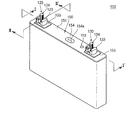
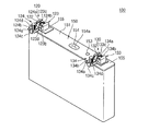
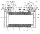
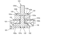
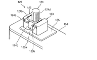
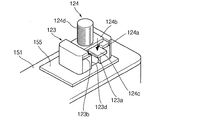
図1は、本発明の一実施形態による2次電池の斜視図である。図2は、本発明の実施形態による2次電池と集電端子とを分離して示す分解斜視図である。図3は、図1のI−I’線断面図である。図4は、図2のA部分拡大図である。図5は、図1のII−II’線拡大図である。図6は、本発明の実施形態による2次電池の電極端子を拡大して示す斜視図である。 FIG. 1 is a perspective view of a secondary battery according to an embodiment of the present invention. FIG. 2 is an exploded perspective view showing a secondary battery and a current collecting terminal separately according to an embodiment of the present invention. FIG. 3 is a cross-sectional view taken along the line I-I ′ of FIG. 1. 4 is an enlarged view of part A of FIG. FIG. 5 is an enlarged view taken along line II-II ′ of FIG. FIG. 6 is an enlarged perspective view showing an electrode terminal of the secondary battery according to the embodiment of the present invention.
図1乃至図6を参照すれば、本発明の実施形態による2次電池100は、電極組立体110、第1端子120、第2端子130、ケース140およびキャップ組立体150を含む。
1 to 6, the
前記電極組立体110は、薄い板型あるいは膜型からなる第1電極板111、第2電極板112およびその間に位置するセパレータ113の積層体を巻き取るか重ねて形成する。ここで、第1電極板111は負極として動作することができ、第2電極板112は正極として動作することができる。もちろん、その逆の場合においても可能である。
The
前記第1電極板111は、銅またはニッケルのような金属箔からなる第1電極集電体に黒鉛または炭素などの第1電極活物質を塗布することによって形成され、第1活物質が塗布されない領域である第1電極無地部111aを含む。前記第1電極無地部111aは、前記第1電極板111間の電流の流れる通路になる。また、前記第1電極板111の材質はこれに限定されるものではない。
The
前記第2電極板112は、アルミニウムのような金属箔からなる第2電極集電体に遷移金属酸化物などの第2電極活物質を塗布することによって形成され、第2活物質が塗布されない領域である第2電極無地部112aを含む。前記第2電極無地部112aは、前記第2電極板112間の電流の流れる通路になる。また、前記第2電極板112の材質はこれに限定されるものではない。
The
前記のような第1電極板111および前記第2電極板112は極性を異にして配置されることもできる。
The
前記セパレータ113は第1電極板111と第2電極板112との間に位置して短絡を防止し、リチウムイオンの移動を可能にする役割を果たし、ポリエチレンやポリプロピレンやポリエチレンとポリプロピレンとの複合フイルムからなることができるが、これに限定されるものではない。
The
前記のような電極組立体110の両側端部には第1電極板111および第2電極板112のそれぞれに電気的に連結される第1端子120および第2端子130が結合する。
The
このような電極組立体110は、実質的に電解液と共に前記ケース140に収納される。前記電解液は、EC(ethylene carbonate)、PC(propylene carbonate)、DEC(dIethyl carbonate)、EMC(ethyl methyl carbonate)およびDMC(dImethyl carbonate)のような有機溶媒にLIPF6、LIBF4のようなリチウム塩からなることができる。また、前記電解液は液体、固体またはゲル状であることができる。
The
前記第1端子120は金属またはその等価物からなり、前記第1電極板111と電気的に連結される。前記第1端子120は、第1集電板121、第1集電端子122、第1端子プレート123および第1締結端子124を含む。
The
前記第1集電板121は、前記電極組立体110の一側端部に突出した第1電極無地部111aと接触される。実質的に、前記第1集電板121は、前記第1電極無地部111aに溶接される。前記第1集電板121は、略L字状に形成され、上部には端子ホール121dが形成される。前記端子ホール121dには前記第1集電端子122が嵌合されて結合する。このような第1集電板121は、例えば銅または銅合金からなるが、これに限定されるものではない。
The first
前記第1集電端子122は、後述するキャッププレート151を貫通して上部に一定の長さが突出および延長され、また、前記キャッププレート151の下部で前記第1集電板121と電気的に連結される。前記第1集電端子122は、前記キャッププレート151の上部に一定の長さが突出および延長される同時に、前記キャッププレート151の下部には、第1集電端子122が前記キャッププレート151から離脱しないように側部方向に延長されたフランジ122aが形成されている。前記第1集電端子122の中、前記フランジ122aの下部に形成された領域は前記第1集電板121の端子ホール121dに嵌合されて溶接される。また、前記第1集電端子122の中、前記フランジ122aの上部に形成された領域は第1端子プレート123に固定される。すなわち、前記第1集電端子122の上端は、後述する第1端子プレート123に結合した後、リベッティングされる。ここで、前記第1集電端子122は、前記キャッププレート151と電気的に絶縁される。このような第1集電端子122は、例えば銅、銅合金およびその等価物のうち選択されるいずれか一つであることができるが、これに限定されるものではない。
The first current collecting
前記第1端子プレート123はボディーを基本にして、その内部に垂直方向に沿って形成された貫通ホール123a、水平方向に形成されたスライド溝123bおよび前記スライド溝123bの上部に形成された固定ステップ123cを備えている。前記第1端子プレート123はほぼ六面体状からなり、前記貫通ホール123aが前記第1端子プレート123の中央にほぼ垂直方向に形成されて、前記第1集電端子122によって貫通結合する。
The first
また、前記第1端子プレート123のほぼ上側内部には水平方向にスライド溝123bが形成され、前記第1締結端子124が前記スライド溝123bに沿って挿入される。
In addition, a
また、前記スライド溝123bの上部には固定ステップ(段差)123cが形成されて、前記スライド溝123bの内部に挿入された前記第1締結端子124を垂直方向に固定させる。
Further, a fixing step (step) 123c is formed on the
また、前記第1端子プレート123の側部には、前記スライド溝123bに垂直方向に形成されている結合溝123dを含む。前記結合溝123dには、後述する前記第1締結端子124のベンディング部124cが結合する。したがって、前記第1締結端子124は、前記第1端子プレート123と結合して水平方向に固定される。
In addition, a side of the first
前記第1端子プレート123は、ステンレススチール、銅、銅合金、アルミニウム、アルミニウム合金およびその等価物のうち選択されるいずれか一つであることができるが、これに限定されるものではない。さらに、前記第1端子プレート123と前記キャッププレート151とは互いに絶縁されている。
The first
前記第1集電端子122と第1端子プレート123とは相互結合および固定されている。すなわち、前記第1集電端子122が、前記第1端子プレート123の貫通ホール123aを貫通した後、前記第1集電端子122の上端がリベッティングされている。したがって、前記第1集電端子122と前記第1端子プレート123とは機械的および電気的に結合している。前記第1集電端子122は上端が前記第1端子プレート123のスライド溝123bと同一平面をなすかまたはさらに低い面をなすように形成されている。したがって、前記第1集電端子122が、前記第1端子プレート123と第1締結端子124との間の締結または結合を妨害しない。
The first current collecting
前記第1締結端子124は、前記第1端子プレート123の上側にスライディング(摺動)されて結合固定される。前記第1締結端子124はボディーを基本にして、下側に位置する挿入部124aを備えている。前記挿入部124aは、前記スライド溝123bに対応する(結合または嵌合可能な)幅および厚さを有するように形成される。このような前記挿入部124aは、前記第1端子プレート123のスライド溝123bに沿って水平方向にスライド(摺動)方式をもって挿入される。
The
また、前記第1締結端子124は、前記挿入部124aの上部に形成された固定部124bを備えている。前記固定部124bは、前記挿入部124aより小さい幅を有するように形成され、前記第1端子プレート123の固定ステップ123cの間の領域に対応する(嵌合可能な)幅を有するように形成される。前記固定部124bは前記固定ステップ123cの間にスライドされ、その結果、前記挿入部124aが前記固定ステップ123cによって垂直方向に固定されることになる。
The
また、前記第1締結端子124は前記挿入部124aの間に形成されたベンディング部124cを備えている。前記ベンディング部124cは前記挿入部124aの間の領域に形成され、前記挿入部124aがスライディングされる方向に前端および後端にそれぞれ形成される。前記ベンディング部124cは、前記第1締結端子124が前記第1端子プレート123のスライド溝123bの内部に挿入された以後、前記第1端子プレート123に向かう方向である下部にほぼ90度に曲げられて(ベンディングされて)形成される。前記ベンディング部124cは、スライディング方向を基準に前記第1端子プレート123の前端および後端を固定することになる。また、前記ベンディング部124cは、前記第1端子プレート123に形成された結合溝123dに締結される。したがって、前記ベンディング部124cと結合溝123dとの結合を通して、前記第1締結端子124はスライディングされる前端および後端に移動できなくなるので、位置が水平方向に固定されることになる。本発明の実施形態においては前記第1締結端子124は、前記端子プレート123に前記固定部124bと固定ステップ123cとの間で溶接部125を通じて溶接されることができる。
The
また、前記第1締結端子124は、前記固定部124bの上部に突出した端子部124dを備えている。前記端子部124dは、表面にバスバーの締結のためのねじ山が形成されることができる。
In addition, the
前記第1締結端子124は、ステンレススチール、銅、銅合金、アルミニウム、アルミニウム合金およびその等価物のうち選択されるいずれか一つであることができるが、これに限定されるものではない。
The
前記第2端子130も主に金属またはその等価物からなり、第2電極板112と電気的に連結される。前記第2端子130は第2集電板131、第2集電端子132、第2端子プレート133および第2締結端子134を含む。ここで、前記第2端子130の形態については、前記第1端子120の形態と同様であるので、詳細な説明は省略する。ただし、前記第2集電板131および第2集電端子132は、主にアルミニウム、アルミニウム合金およびその等価物のうち選択されるいずれか一つであることができるが、これに限定されるものではない。また、前記第2端子プレート133および第2締結端子134は、主にステンレススチール、アルミニウム、アルミニウム合金、銅、銅合金およびその等価物のうち選択されるいずれか一つであることができるが、これに限定されるものではない。
The
また、前記第2端子プレート133は前記キャッププレート151と電気的に連結されることができるので、後述するケース140およびキャッププレート151は、前記第2端子130のような極性(例えば、正極)を有することができる。
In addition, since the second
前記ケース140は、アルミニウム、アルミニウム合金またはニッケルがメッキされたスチールのような導電性金属からなり、電極組立体110、第1端子120および第2端子130が挿入安着できる開口部が形成されたほぼ六面体状からなる。図3においては、ケース140とキャップ組立体150とが結合した状態に示しているので、開口部を示してはいないが、実質的にはキャップ組立体150の周りの部分が開放されている。一方、ケース140の内面は絶縁処理されて、電極組立体110、第1端子120、第2端子130およびキャップ組立体150と絶縁されることができる。
The
前記キャップ組立体150は前記ケース140に結合する。前記キャップ組立体150は、具体的にはキャッププレート151、シールガスケット152、栓153、安全ベント154、第1絶縁部材155および第2絶縁部材156を含む。もちろん、前記シールガスケット152、第1絶縁部材155および第2絶縁部材156は前記第1端子120および第2端子130の構成要素に見ることもできる。
The
前記キャッププレート151は前記ケース140の開口を密封し、前記ケース140と同じ材質からなることができる。例えば、前記キャッププレート151は、レーザー溶接方式で前記ケース140に結合することができる。ここで、前記キャッププレート151は前述のように、前記第2端子130と同じ極性を持てるので、前記キャッププレート151およびケース140は同じ極性を持てる。
The
前記シールガスケット152は絶縁性材質からなり、前記第1集電端子122、前記第2集電端子132のそれぞれと前記キャッププレート151の間に形成されて、前記第1集電端子122および第2集電端子132のそれぞれとキャッププレート151との間を密封させる。このようなシールガスケット152は外部の水分が2次電池100の内部に侵入しないようにしたり、2次電池100の内部に収容された電解液が外部に流出しないようにする。
The
前記栓153は、前記キャッププレート151の電解液注入口151aを密封し、前記安全ベント154はキャッププレート151のベントホール151bに設置され、設定された圧力によって開放されるようにノッチ154aが形成されることができる。
The
前記第1絶縁部材155は、前記第1端子プレート123、第2端子プレート133のそれぞれとキャッププレート151の間に形成される。また、前記第1絶縁部材155は前記キャッププレート151と密着する。さらに、前記第1絶縁部材155は前記シールガスケット152にも密着できる。このような前記第1絶縁部材155は、前記第1端子プレート123および第2端子プレート133のそれぞれとキャッププレート151とを絶縁させる。
The first insulating
前記第2絶縁部材156は、前記第1集電板121、第2集電板131のそれぞれとキャッププレート151の間に形成されて、不必要な電気的短絡の発生を防止する。すなわち、前記第2絶縁部材156は、前記第1集電板121とキャッププレート151との間の短絡、そして前記第2集電板131とキャッププレート151との間の短絡を防止する。さらに、このような第2絶縁部材156は前記第1集電端子122、第2集電端子132のそれぞれとキャッププレート151の間にも形成されることによって、前記第1集電端子122、第2集電端子132のそれぞれと前記キャッププレート151の間の不必要な短絡も防止することになる。
The second insulating
前記のようにして、本発明の実施形態による2次電池100は端子120、130を形成する際に、集電端子122、132を端子プレート123、133にリベット締結して固定させた状態で、端子プレート123、133に締結端子124、134をスライディング挿入して締結端子124、134の水平位置を固定させる。また、締結端子124、134のベンディング部124c、134cを曲げることによって、締結端子124、134の垂直位置を固定させる。したがって、締結端子124、134を端子プレート123、133に強く結合することによって締結力を向上させることができ、電気的抵抗を減らすことができる。また、別途の溶接なしに締結力が向上するので、組立性を向上させることができる。
As described above, in the
以下、本発明の実施形態による2次電池の電極端子内の電流の経路について説明する。 Hereinafter, a current path in the electrode terminal of the secondary battery according to the embodiment of the present invention will be described.
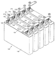
図7は、本発明の実施形態による2次電池とバスバーとの結合方法を示す分解斜視図である。図8aおよび図8bは、本発明の実施形態による2次電池の電極端子における電流の経路を示す図であって、矢印は放電電流の経路を示すものである。 FIG. 7 is an exploded perspective view illustrating a method of coupling the secondary battery and the bus bar according to the embodiment of the present invention. 8a and 8b are diagrams illustrating current paths in electrode terminals of the secondary battery according to the embodiment of the present invention, and arrows indicate discharge current paths.
図7および図8aを参照すれば、電池パックを形成するためにバスバー310は締結端子124に結合する。つまり、バスバー310の貫通ホール310dに締結端子124の端子部124bが結合する。また、前記バスバー310の上部領域と対応する端子部124bにはナット311が結合することによって、前記バスバー310は端子プレート123に強く密着する。したがって、集電端子122とバスバー310との間に相対的に断面積が大きい端子プレート123を介在することによって電流通路が増加し、なお、接触電気抵抗が減少する。また、図8bを参照すれば、場合によって、前記バスバー310およびナット311は前記端子プレート123の固定ステップ123cの内側に位置して結合することも可能である。
7 and 8a, the
一方、前記バスバー310は、ステンレススチール、アルミニウム、アルミニウム合金、銅、銅合金およびその等価物のうち選択されるいずれか一つであることができるが、これに限定されるものではない。
Meanwhile, the
前述のように、前記端子プレート123、133と前記締結端子124、134は互いに材質が同じかまたは異なることがある。さらに、前記端子プレート123、133と前記バスバー310なお互いに材質が同じかまたは異なることがある。本発明の実施形態による2次電池100は、リベッティング方法で集電端子122、132と端子プレート123、133とが締結される。そして、前記締結端子124、134は前記端子プレート123、133のスライド部123b、133bにスライディング挿入された以降、ベンディング部124c、134cの変形を通して強く固定される。また、前記締結端子124とバスバー310とがナット311によって結合するので、異種材料間の結合の際にも電気抵抗が大きく増加しないことになる。
As described above, the
以下、本発明の実施形態による2次電池の組み立て方法について説明する。 Hereinafter, a method for assembling a secondary battery according to an embodiment of the present invention will be described.
図9a乃至図9fは、本発明の実施形態による2次電池の組み立て方法を説明した順次説明図である。 9a to 9f are sequential explanatory diagrams illustrating a method for assembling a secondary battery according to an embodiment of the present invention.
図9aに示すように、まず、前記第1集電端子122がキャッププレート151に結合する。もちろん、このとき、前記第1集電端子122はシールガスケット152によってキャッププレート151と電気的に絶縁される。ここで、前記キャッププレート151の表面には突起151bが形成されており、前記突起151は後述する第1絶縁部材155の凹溝に結合する。
As shown in FIG. 9 a, first, the first current collecting
図9bに示すように、前記第1集電端子122に第1絶縁部材155が結合する。言い換えると、前記第1絶縁部材155に貫通ホール155dが形成されており、前記貫通ホール155dに前記第1集電端子122が貫通、結合する。
As shown in FIG. 9 b, a first insulating
もちろん、前記第1絶縁部材155は前記キャッププレート151に安着し、なお、前記突起151bに結合している。したがって、前記第1絶縁部材155は、前記第1集電端子122を中心に回転しない。さらに、前記第1集電端子122は、依然として前記第1絶縁部材155を貫通して上部に一定の長さに延長されている。
Of course, the first insulating
図9cに示すように、第1端子プレート123が前記第1集電端子122に結合する。より詳しくは、前記第1端子プレート123は本体中央に貫通ホール123aが形成されており、前記貫通ホール123aには前記第1集電端子122が貫通、結合している。もちろん、このとき、前記第1端子プレート123は前記第1絶縁部材155に密着する。したがって、前記第1端子プレート123とキャッププレート151とは電気的に絶縁される。
As shown in FIG. 9 c, the first
さらに、前記第1集電端子122の上端はリベッティングツールによってリベッティングされる。このとき、前記第1端子プレート123の貫通ホール123aの周辺に形成された溝に前記第1集電端子122の上端がリベッティングされる。したがって、前記リベッティングによって前記第1集電端子122の上端は前記第1端子プレート123のスライド溝123bより下部に位置することになり、以降、第1締結端子124の締結を妨害しないことになる。
Further, the upper end of the first current collecting
図9dに示すように、第1締結端子124が前記第1端子プレート123に結合する。より詳しくは、前記第1締結端子124は一対のベンディング部124cの中、一つを下部に向かってほぼ90度に曲げた反面、残り一つは、挿入部124aと水平状態を維持することができる。また、前記第1締結端子124は水平に維持されたベンディング部124cを前方向にして、前記第1端子プレート123のスライド溝123bの内部に挿入部124aが挿入された状態で水平にスライディングされる。そして、前記スライディング動作は、後端に位置する曲げられたベンディング部124cが前記第1端子プレート123の結合溝123dに結合する時点まで行われるようになる。このとき、前記第1端子プレート123の固定ステップ123cは前記締結端子124の挿入部124aを上部から固定させるので、前記第1締結端子124の垂直方向での位置が固定される。
As shown in FIG. 9 d, the
図9eおよび図9fに示すように、前端の水平状態を維持するベンディング部124cは、プレスを通してほぼ90度に垂直に曲げられる。前記ベンディング部124cは曲げられて、前記第1端子プレート123の結合溝123dと結合する。したがって、前記第1締結端子124の前端および後端に位置するベンディング部124cがほぼ90度に曲げられて前記第1端子プレート123と結合するので、前記第1締結端子124の水平方向における位置も固定される。
As shown in FIGS. 9e and 9f, the bending
以上の説明は、本発明による2次電池およびその組み立て方法を実施するための一つの実施形態に過ぎないものであって、本発明は前記実施形態に限定されるものではなく、以下の特許請求の範囲において請求するように、本発明の要旨を逸脱することなく当該発明の属する分野で通常の知識を有する者であれば、誰でも多様な変更実施が可能な範囲にまで本発明の技術的精神がいるとみなされる。 The above description is only one embodiment for carrying out the secondary battery and the method for assembling the same according to the present invention, and the present invention is not limited to the above-described embodiment, and the following claims are given. As claimed in the scope of the present invention, any person who has ordinary knowledge in the field to which the present invention belongs without departing from the gist of the present invention can be applied to the technical scope of the present invention to the extent that various modifications can be made. It is considered that there is a spirit.
100 2次電池
110 電極組立体
120 第1端子
121 第1集電板
122 第1集電端子
123 第1端子プレート
124 第1締結端子
130 第2端子
131 第2集電板
132 第2集電端子
133 第2端子プレート
134 第2締結端子
140 ケース
150 キャップ組立体
151 キャッププレート
152 シールガスケット
153 栓
154 安全ベント
155 第1絶縁部材
156 第2絶縁部材
100
Claims (19)
前記電極組立体に電気的に連結される集電端子と、
前記集電端子に電気的に連結され、その上面にスライド溝を含む端子プレートと、
前記集電プレートに電気的に連結され、前記端子プレートのスライド溝に結合した締結端子と、
を含むことを特徴とする、2次電池。 An electrode assembly;
A current collecting terminal electrically connected to the electrode assembly;
A terminal plate electrically connected to the current collecting terminal and including a slide groove on an upper surface thereof;
A fastening terminal electrically connected to the current collecting plate and coupled to a slide groove of the terminal plate;
A secondary battery comprising:
前記ベンディング部は前記端子プレートの側面にベンディングされることを特徴とする、請求項1または2に記載の2次電池。 The fastening terminal includes a bending portion,
The secondary battery according to claim 1, wherein the bending part is bent on a side surface of the terminal plate.
前記締結端子のベンディング部は、前記端子プレートの結合溝に結合することを特徴とする、請求項3に記載の2次電池。 The terminal plate includes a coupling groove on a horizontal side surface,
The secondary battery according to claim 3, wherein the bending portion of the fastening terminal is coupled to a coupling groove of the terminal plate.
前記挿入部は、前記端子プレートのスライド溝と締結されることを特徴とする、請求項6に記載の2次電池。 The fastening terminal includes a body part and an insertion part below the body part,
The secondary battery according to claim 6, wherein the insertion part is fastened with a slide groove of the terminal plate.
前記固定部の幅は、前記挿入部の幅より小さいことを特徴とする、請求項7または8に記載の2次電池。 The fastening terminal further includes a fixing part at an upper part of the insertion part,
The secondary battery according to claim 7, wherein a width of the fixing portion is smaller than a width of the insertion portion.
前記集電端子は、前記貫通孔に位置することを特徴とする、請求項1〜12のいずれか1項に記載の2次電池。 The terminal plate includes a through hole in the center thereof,
The secondary battery according to claim 1, wherein the current collecting terminal is located in the through hole.
前記集電端子の上面にスライド溝を含む端子プレートを結合する段階と、
前記端子プレートのスライド溝に締結端子を挿入することによって、端子プレートに締結端子をスライディングさせて結合する段階と、
を含むことを特徴とする、2次電池の組み立て方法。 Coupling a current collecting terminal to the electrode assembly;
Coupling a terminal plate including a slide groove on the upper surface of the current collecting terminal;
Sliding and coupling the fastening terminal to the terminal plate by inserting the fastening terminal into the slide groove of the terminal plate; and
A method for assembling a secondary battery, comprising:
前記締結端子をスライディングさせて結合する段階では、前記ベンディング部の第1端部が下方にベンディングされ、前記ベンディング部の第2端部が前記締結端子の挿入方向から平行に延長された状態で前記端子プレートのスライド溝に前記締結端子を挿入することを特徴とする、請求項14に記載の2次電池の組み立て方法。 The fastening terminal includes a bending portion on a side surface,
In the step of sliding and coupling the fastening terminal, the first end of the bending part is bent downward, and the second end of the bending part is extended in parallel from the insertion direction of the fastening terminal. The method of assembling a secondary battery according to claim 14, wherein the fastening terminal is inserted into a slide groove of a terminal plate.
前記締結端子をスライディング締結する段階は、前記ベンディング部の第1および第2端部を前記結合溝に結合する段階を含むことを特徴とする、請求項16または17に記載の2次電池の組み立て方法。 The terminal plate includes coupling grooves on the first and second side surfaces,
The rechargeable battery assembly of claim 16 or 17, wherein the step of slidingly fastening the fastening terminal includes a step of coupling first and second ends of the bending portion to the coupling groove. Method.
それぞれの前記2次電池は、
電極組立体と、
前記電極組立体に電気的に連結される集電端子と、
前記集電端子に電気的に連結され、上部にスライド溝を含む端子プレートと、
前記端子プレートと結合し、前記端子プレートのスライド溝とスライド結合する締結端子と、
を含み、
少なくとも二つの前記2次電池を電気的に連結し、少なくとも二つの前記2次電池の端子プレートを電気的に連結するバスバーを含むことを特徴とする、バッテリーパック。
In a battery pack including a plurality of secondary batteries,
Each of the secondary batteries is
An electrode assembly;
A current collecting terminal electrically connected to the electrode assembly;
A terminal plate electrically connected to the current collecting terminal and including a slide groove at an upper portion;
A fastening terminal that is coupled to the terminal plate and is slidably coupled to a slide groove of the terminal plate;
Including
A battery pack comprising: a bus bar for electrically connecting at least two of the secondary batteries and electrically connecting terminal plates of the at least two of the secondary batteries.
Applications Claiming Priority (4)
| Application Number | Priority Date | Filing Date | Title |
|---|---|---|---|
| US201161431516P | 2011-01-11 | 2011-01-11 | |
| US61/431516 | 2011-01-11 | ||
| US13/193,893 US20120177978A1 (en) | 2011-01-11 | 2011-07-29 | Secondary battery, method of assembling the same, and battery pack including the secondary battery |
| US13/193893 | 2011-07-29 |
Publications (1)
| Publication Number | Publication Date |
|---|---|
| JP2012146664A true JP2012146664A (en) | 2012-08-02 |
Family
ID=44785518
Family Applications (1)
| Application Number | Title | Priority Date | Filing Date |
|---|---|---|---|
| JP2012003463A Ceased JP2012146664A (en) | 2011-01-11 | 2012-01-11 | Secondary battery, assembly method thereof and battery pack including the same |
Country Status (5)
| Country | Link |
|---|---|
| US (1) | US20120177978A1 (en) |
| EP (1) | EP2475031A1 (en) |
| JP (1) | JP2012146664A (en) |
| KR (1) | KR20120081547A (en) |
| CN (1) | CN102593404A (en) |
Cited By (3)
| Publication number | Priority date | Publication date | Assignee | Title |
|---|---|---|---|---|
| JP2013161692A (en) * | 2012-02-07 | 2013-08-19 | Gs Yuasa Corp | Power storage element, power storage element group |
| US10135040B2 (en) | 2012-12-25 | 2018-11-20 | Gs Yuasa International Ltd. | Electric storage device, electric storage device assembly, and method for producing electric storage device |
| JP2022049729A (en) * | 2020-09-17 | 2022-03-30 | プライムプラネットエナジー&ソリューションズ株式会社 | Terminal, secondary battery with the same, and manufacturing method thereof |
Families Citing this family (10)
| Publication number | Priority date | Publication date | Assignee | Title |
|---|---|---|---|---|
| WO2013029483A1 (en) * | 2011-08-29 | 2013-03-07 | 深圳市比亚迪汽车研发有限公司 | Battery connection piece and battery group having the battery connection piece |
| KR20140072591A (en) * | 2012-12-05 | 2014-06-13 | 삼성에스디아이 주식회사 | Secondary battery and Secondary battery assembly |
| KR101553583B1 (en) * | 2014-01-28 | 2015-09-16 | 삼성에스디아이 주식회사 | Secondary battery |
| KR102248594B1 (en) * | 2014-04-07 | 2021-05-06 | 삼성에스디아이 주식회사 | Electrode terminal and battery module including the same |
| KR102164010B1 (en) * | 2014-05-28 | 2020-10-12 | 삼성에스디아이 주식회사 | Rechargeable battery |
| KR102273777B1 (en) * | 2014-08-08 | 2021-07-06 | 삼성에스디아이 주식회사 | Secondary battery and secondary battery module having the same |
| KR102323949B1 (en) * | 2015-03-03 | 2021-11-08 | 삼성에스디아이 주식회사 | Rechargeable battery having upper cover |
| US10403875B2 (en) | 2015-04-14 | 2019-09-03 | Ford Global Technologies, Llc | Busbar assembly for vehicle traction battery |
| JP6380420B2 (en) * | 2016-02-04 | 2018-08-29 | トヨタ自動車株式会社 | Secondary battery and battery pack |
| CN108428823B (en) | 2017-08-30 | 2024-02-13 | 宁德时代新能源科技股份有限公司 | Top cap subassembly and secondary cell of secondary cell |
Citations (2)
| Publication number | Priority date | Publication date | Assignee | Title |
|---|---|---|---|---|
| JP2008300334A (en) * | 2007-06-04 | 2008-12-11 | Sony Ericsson Mobilecommunications Japan Inc | Battery pack |
| US20100143786A1 (en) * | 2008-12-08 | 2010-06-10 | Samsung Sdi Co., Ltd. | Rechargeable battery and battery module using the same |
Family Cites Families (9)
| Publication number | Priority date | Publication date | Assignee | Title |
|---|---|---|---|---|
| US1939105A (en) * | 1931-02-28 | 1933-12-12 | George W Thompson | Battery terminal connecter |
| US7045246B2 (en) * | 2003-04-22 | 2006-05-16 | The Aerospace Corporation | Integrated thin film battery and circuit module |
| KR100778511B1 (en) * | 2006-09-11 | 2007-11-22 | 삼성에스디아이 주식회사 | Rechargeable battery module |
| JP4974734B2 (en) * | 2006-10-10 | 2012-07-11 | 三星エスディアイ株式会社 | Secondary battery and secondary battery module |
| JP5288973B2 (en) * | 2008-09-29 | 2013-09-11 | 三洋電機株式会社 | Rectangular secondary battery and battery module |
| JP5430978B2 (en) * | 2009-03-10 | 2014-03-05 | 三洋電機株式会社 | Sealed battery and manufacturing method thereof |
| KR101023105B1 (en) * | 2009-03-11 | 2011-03-24 | 에스비리모티브 주식회사 | Rechargable battery |
| US8916287B2 (en) * | 2010-08-16 | 2014-12-23 | Samsung Sdi Co., Ltd. | Rechargeable battery |
| US8309246B2 (en) * | 2010-10-25 | 2012-11-13 | Sb Limotive Co., Ltd. | Terminal of rechargeable battery and method of manufacturing the same |
-
2011
- 2011-07-29 US US13/193,893 patent/US20120177978A1/en not_active Abandoned
- 2011-09-29 EP EP11183247A patent/EP2475031A1/en not_active Withdrawn
- 2011-11-30 KR KR1020110127378A patent/KR20120081547A/en not_active Application Discontinuation
-
2012
- 2012-01-10 CN CN2012100057867A patent/CN102593404A/en active Pending
- 2012-01-11 JP JP2012003463A patent/JP2012146664A/en not_active Ceased
Patent Citations (2)
| Publication number | Priority date | Publication date | Assignee | Title |
|---|---|---|---|---|
| JP2008300334A (en) * | 2007-06-04 | 2008-12-11 | Sony Ericsson Mobilecommunications Japan Inc | Battery pack |
| US20100143786A1 (en) * | 2008-12-08 | 2010-06-10 | Samsung Sdi Co., Ltd. | Rechargeable battery and battery module using the same |
Cited By (4)
| Publication number | Priority date | Publication date | Assignee | Title |
|---|---|---|---|---|
| JP2013161692A (en) * | 2012-02-07 | 2013-08-19 | Gs Yuasa Corp | Power storage element, power storage element group |
| US10135040B2 (en) | 2012-12-25 | 2018-11-20 | Gs Yuasa International Ltd. | Electric storage device, electric storage device assembly, and method for producing electric storage device |
| JP2022049729A (en) * | 2020-09-17 | 2022-03-30 | プライムプラネットエナジー&ソリューションズ株式会社 | Terminal, secondary battery with the same, and manufacturing method thereof |
| JP7214692B2 (en) | 2020-09-17 | 2023-01-30 | プライムプラネットエナジー&ソリューションズ株式会社 | Terminal, secondary battery with the same, and manufacturing method thereof |
Also Published As
| Publication number | Publication date |
|---|---|
| CN102593404A (en) | 2012-07-18 |
| KR20120081547A (en) | 2012-07-19 |
| US20120177978A1 (en) | 2012-07-12 |
| EP2475031A1 (en) | 2012-07-11 |
Similar Documents
| Publication | Publication Date | Title |
|---|---|---|
| JP2012146664A (en) | Secondary battery, assembly method thereof and battery pack including the same | |
| KR101146414B1 (en) | Rechargeable battery | |
| TWI466356B (en) | Battery and its manufacturing method | |
| EP3451416B1 (en) | Second battery | |
| KR101274859B1 (en) | Secondary Battery And Assembling Method thereof | |
| EP2958162B1 (en) | Secondary battery | |
| JP6679204B2 (en) | Rechargeable battery | |
| KR101254886B1 (en) | Secondary battery | |
| KR101222232B1 (en) | Secondary battery | |
| US9012065B2 (en) | Secondary battery and battery pack having the same | |
| EP3451415B1 (en) | Secondary battery | |
| KR20120106539A (en) | Secondary battery and secondary battery pack | |
| JP6438248B2 (en) | Secondary battery | |
| US10211446B2 (en) | Rechargeable battery | |
| US9692034B2 (en) | Secondary battery | |
| KR101222261B1 (en) | Rechargeable battery | |
| KR101658973B1 (en) | Pouch type secondary battery and secondary battery module comprising the same | |
| KR102337491B1 (en) | Secondary battery | |
| KR20170060448A (en) | Secondary Battery and Method for Manufacturing The Same | |
| KR20140090902A (en) | Secondary bttery and secondary bttery module | |
| KR20190024619A (en) | Secondary Battery | |
| KR20230092267A (en) | Secondary Battery |
Legal Events
| Date | Code | Title | Description |
|---|---|---|---|
| A711 | Notification of change in applicant |
Free format text: JAPANESE INTERMEDIATE CODE: A711 Effective date: 20121226 |
|
| A621 | Written request for application examination |
Free format text: JAPANESE INTERMEDIATE CODE: A621 Effective date: 20141218 |
|
| A977 | Report on retrieval |
Free format text: JAPANESE INTERMEDIATE CODE: A971007 Effective date: 20151013 |
|
| A131 | Notification of reasons for refusal |
Free format text: JAPANESE INTERMEDIATE CODE: A131 Effective date: 20151020 |
|
| A521 | Request for written amendment filed |
Free format text: JAPANESE INTERMEDIATE CODE: A523 Effective date: 20160119 |
|
| A01 | Written decision to grant a patent or to grant a registration (utility model) |
Free format text: JAPANESE INTERMEDIATE CODE: A01 Effective date: 20160209 |
|
| A045 | Written measure of dismissal of application [lapsed due to lack of payment] |
Free format text: JAPANESE INTERMEDIATE CODE: A045 Effective date: 20160628 |