JP5977226B2 - Internal nozzle for pouring molten metal contained in metallurgical vessel and molten metal pouring device - Google Patents
Internal nozzle for pouring molten metal contained in metallurgical vessel and molten metal pouring device Download PDFInfo
- Publication number
- JP5977226B2 JP5977226B2 JP2013500369A JP2013500369A JP5977226B2 JP 5977226 B2 JP5977226 B2 JP 5977226B2 JP 2013500369 A JP2013500369 A JP 2013500369A JP 2013500369 A JP2013500369 A JP 2013500369A JP 5977226 B2 JP5977226 B2 JP 5977226B2
- Authority
- JP
- Japan
- Prior art keywords
- nozzle
- bearing
- metal
- triangle
- plate
- Prior art date
- Legal status (The legal status is an assumption and is not a legal conclusion. Google has not performed a legal analysis and makes no representation as to the accuracy of the status listed.)
- Active
Links
Images


Classifications
-
- B—PERFORMING OPERATIONS; TRANSPORTING
- B22—CASTING; POWDER METALLURGY
- B22D—CASTING OF METALS; CASTING OF OTHER SUBSTANCES BY THE SAME PROCESSES OR DEVICES
- B22D41/00—Casting melt-holding vessels, e.g. ladles, tundishes, cups or the like
- B22D41/14—Closures
- B22D41/22—Closures sliding-gate type, i.e. having a fixed plate and a movable plate in sliding contact with each other for selective registry of their openings
- B22D41/40—Means for pressing the plates together
-
- B—PERFORMING OPERATIONS; TRANSPORTING
- B22—CASTING; POWDER METALLURGY
- B22D—CASTING OF METALS; CASTING OF OTHER SUBSTANCES BY THE SAME PROCESSES OR DEVICES
- B22D41/00—Casting melt-holding vessels, e.g. ladles, tundishes, cups or the like
- B22D41/14—Closures
- B22D41/22—Closures sliding-gate type, i.e. having a fixed plate and a movable plate in sliding contact with each other for selective registry of their openings
- B22D41/28—Plates therefor
- B22D41/34—Supporting, fixing or centering means therefor
-
- B—PERFORMING OPERATIONS; TRANSPORTING
- B22—CASTING; POWDER METALLURGY
- B22D—CASTING OF METALS; CASTING OF OTHER SUBSTANCES BY THE SAME PROCESSES OR DEVICES
- B22D41/00—Casting melt-holding vessels, e.g. ladles, tundishes, cups or the like
- B22D41/50—Pouring-nozzles
- B22D41/56—Means for supporting, manipulating or changing a pouring-nozzle
-
- Y—GENERAL TAGGING OF NEW TECHNOLOGICAL DEVELOPMENTS; GENERAL TAGGING OF CROSS-SECTIONAL TECHNOLOGIES SPANNING OVER SEVERAL SECTIONS OF THE IPC; TECHNICAL SUBJECTS COVERED BY FORMER USPC CROSS-REFERENCE ART COLLECTIONS [XRACs] AND DIGESTS
- Y10—TECHNICAL SUBJECTS COVERED BY FORMER USPC
- Y10T—TECHNICAL SUBJECTS COVERED BY FORMER US CLASSIFICATION
- Y10T29/00—Metal working
- Y10T29/49—Method of mechanical manufacture
- Y10T29/49826—Assembling or joining
Description
本発明は、連続溶融鋳造の分野に関し、より具体的には、金属鋳造設備において管交換装置に内部ノズルを固定する特定手段を有する内部ノズルに関する。 The present invention relates to the field of continuous melt casting, and more specifically to an internal nozzle having specific means for fixing the internal nozzle to a pipe changer in a metal casting facility.
鋳造設備においては、溶融金属は、別容器、例えば鋳型内に流し込まれる前には、一般に冶金容器、例えばタンディッシュ内に含まれている。金属は、冶金容器から、冶金容器の基底部に設けられたノズルシステムを介して別容器に流し込まれる。ノズルシステムは、冶金容器内に少なくとも部分的に位置決めされた内部ノズルを含み、この内部ノズルはスライド流し込みプレート(又は鋳造プレート)と密着接触する。スライド流し込みプレートは冶金容器の下方で、且つ外側に位置決めされており、冶金容器の下側に取り付けられたプレート保持交換装置を介して内部ノズルと整列させられる。このスライドプレートは、較正プレート、鋳造管、又は2つ又は3つ以上のプレートを含む匣鉢(サガー)であってもよい。これら全てのタイプのプレートは、用途に応じて様々な長さの管状区分に結合されたプレートを含むノズルの部分であり、またこれらのノズルを例えば取鍋内で使用されるバルブゲートと区別するために、ここでは「スライドノズル」、「注入ノズル」、「交換可能注入ノズル」、又はこれらの組み合わせで呼ぶことにする。注入ノズルの使用により、短管を用いて自由流動の形態で、又は部分的に浸漬されたより長い鋳造管を用いて誘導流の形態で、溶融金属を流し込むことができる。 In a casting facility, the molten metal is generally contained in a metallurgical vessel, such as a tundish, before being poured into a separate vessel, such as a mold. The metal is poured from the metallurgical vessel into another vessel through a nozzle system provided at the base of the metallurgical vessel. The nozzle system includes an internal nozzle positioned at least partially within the metallurgical vessel, the internal nozzle being in intimate contact with a slide casting plate (or cast plate). The slide casting plate is positioned below and outside of the metallurgical vessel and is aligned with the internal nozzle via a plate holding and exchanging device attached to the underside of the metallurgical vessel. The slide plate may be a calibration plate, a cast tube, or a sag containing two or more plates. All these types of plates are part of a nozzle that includes plates coupled to tubular sections of various lengths depending on the application, and also distinguish these nozzles from valve gates used, for example, in a ladle For this reason, they are referred to herein as “slide nozzles”, “injection nozzles”, “replaceable injection nozzles”, or combinations thereof. Through the use of an injection nozzle, the molten metal can be poured in the form of a free flow using a short tube or in the form of an induced flow using a partially cast longer casting tube.
鋳造設備のための管交換装置の一例が、欧州特許第1289696号明細書に記載されている。内部ノズルとスライドノズルとの間に密着接触を提供するために、注入ノズルを保持交換する管交換装置は、装置のフレームに対して内部ノズルを下方向にクランプするように意図されたクランプ手段を含み、また、注入ノズルのプレートを、特に上方向に押圧するように意図された加圧手段を含むことにより、プレートを内部ノズルに押し付け、そして密着接触を得る。 An example of a pipe changer for a casting facility is described in EP 1289696. In order to provide intimate contact between the inner nozzle and the slide nozzle, the tube changer holding and exchanging the injection nozzle has clamping means intended to clamp the inner nozzle downward relative to the frame of the device. Including, and by including pressurizing means intended to press the plate of the injection nozzle, in particular upwards, press the plate against the internal nozzle and obtain intimate contact.
上記のように、内部ノズルは、鋳造中、固定された要素である。従って、その耐用寿命は少なくとも、冶金容器のうちの1つと同じ長さであるべきである。他方、注入ノズルは、管交換装置によって鋳造中に交換することができる。 As mentioned above, the internal nozzle is a fixed element during casting. Therefore, its useful life should be at least as long as one of the metallurgical vessels. On the other hand, the injection nozzle can be changed during casting by means of a tube changer.
欧州特許第1454687号明細書に開示されたコレクタノズルは、取鍋の底部に位置決めされたゲートバルブのスライド・ゲートに結合されており、溶融金属をタンディッシュに注入するために使用される。タンディッシュの内部ノズルと同様に、欧州特許第1454687号明細書に開示されたコレクタノズルは、管状部分とプレートとを有する耐火コアを含む。コレクタノズルの外面の大部分は、金属ケーシングで被覆されている。2つのタイプのノズル間の類似性はここまでである。実際に、本発明の対象である内部ノズルとは異なり、取鍋のコレクタノズルは使用中、いかなる摩擦応力も受けない。それというもの、これはスライド・ゲート・バルブのスライド・ゲート・プレートに固定的に取り付けられているからである。さらに、コレクタノズルは、取鍋の底部に懸吊されているのに対して、内部ノズルは、管交換装置のフレーム上側部分に配置されている。2タイプのノズル用に使用されるクランプ手段は、結果として、互いに大きく異なる。欧州特許第1454687号明細書に開示されたコレクタノズルの場合、ノズルは、フランジを含む第1金属シリンダ内に導入される。このフランジは、スライド・ゲート・バルブのスライドプレートの下側部分にねじによって固定された第2金属シリンダと、バヨネットとして係合する。第1金属シリンダ及び第2金属シリンダのいずれもコレクタノズルの部分ではなく、むしろスライド・ゲート・プレートの下面にコレクタノズルを固定するために使用されるクランプ手段である。冶金容器に対するノズルのこのようなクランプ解決策は、管交換装置のフレーム上側部分に内部ノズルをクランプするのに適してはいない。 The collector nozzle disclosed in EP 1454687 is coupled to a sliding gate of a gate valve positioned at the bottom of the ladle and is used to inject molten metal into the tundish. Similar to the tundish internal nozzle, the collector nozzle disclosed in EP 1454687 includes a refractory core having a tubular portion and a plate. Most of the outer surface of the collector nozzle is covered with a metal casing. This is the similarity between the two types of nozzles. In fact, unlike the internal nozzle that is the subject of the present invention, the collector nozzle of the ladle is not subjected to any frictional stress during use. That is because it is fixedly attached to the slide gate plate of the slide gate valve. Furthermore, the collector nozzle is suspended from the bottom of the ladle, whereas the internal nozzle is arranged in the upper part of the frame of the pipe changer. The clamping means used for the two types of nozzles are consequently very different from each other. In the case of the collector nozzle disclosed in EP 1454687, the nozzle is introduced into a first metal cylinder containing a flange. This flange engages as a bayonet with a second metal cylinder secured by screws to the lower portion of the slide plate of the slide gate valve. Neither the first metal cylinder nor the second metal cylinder is a part of the collector nozzle, but rather a clamping means used to fix the collector nozzle to the lower surface of the slide gate plate. Such a clamping solution for the nozzle against the metallurgical vessel is not suitable for clamping the internal nozzle to the upper part of the frame of the tube changer.
内部ノズル及び注入ノズルのプレートは、各々、少なくとも部分的に耐火材料を含む。1つの問題点は、クランプ手段又は加圧手段によって加えられた力が、耐火材料に応力集中をもたらす傾向を有することがある。これらの応力集中は、脆弱な耐火材料を損傷し、亀裂を形成するか又は崩壊を招くおそれがある。 The inner nozzle and injection nozzle plates each comprise at least a portion of a refractory material. One problem may be that the force applied by the clamping means or pressing means tends to cause stress concentrations in the refractory material. These stress concentrations can damage fragile refractory materials, form cracks or cause collapse.
本発明の目的は、ノズル及び冶金容器双方の全耐用寿命にわたって材料品質及び完全性が維持される内部ノズルを提供することである。 It is an object of the present invention to provide an internal nozzle that maintains material quality and integrity over the entire useful life of both the nozzle and the metallurgical vessel.
本発明は、追加された独立請求項に定義される。好ましい実施例は、従属請求項に定義れる。特に、本発明は、下記内部ノズルに関する。
冶金容器からの溶融金属の流し込み用内部ノズルであって、該内部ノズルは、
a) 流入開口と流出開口とを流体接続する、第1方向(Z)を定義する軸方向貫通孔を有する略管状部分を含み、
b) スライド平面(Pg)と称される、周囲(Pm)内部に包囲された平坦な底部接触面を有する内部ノズルプレートを含み、前記スライド平面は前記第1方向(Z)に対して略垂直であり、前記接触面は、前記流出開口を含み、前記内部ノズルプレートは、さらに、前記管状部分の壁を前記プレートの側縁部に接合する、前記底部接触面とは反対側の第2面を含み、前記側縁部は、前記底部接触面から前記第2面へ延び、前記プレートの周囲及び厚さを定義しており、さらに
c) 前記内部ノズルプレートの前記側縁部及び第2面のいくつか又は全てのうちの少なくとも一部を被覆するが、スライド平面(Pg)を被覆しない金属ケーシングを含み、前記金属ケーシングは
d) 金属支承面を含み、前記金属支承面は、前記スライド平面(Pg)に面しており、且つ前記スライド平面(Pg)に対して凹んでおり、そして前記接触面の周囲(Pm)を超えて、前記側縁部の被覆部分から延びている内部ノズルであって、
前記支承面が、前記プレートの周囲に配置された少なくとも2つの別個の支承要素の前記レッジによって形成される、ことを特徴とする。
The invention is defined in the appended independent claims. Preferred embodiments are defined in the dependent claims. In particular, the present invention relates to the following internal nozzles.
An internal nozzle for pouring molten metal from a metallurgical vessel, the internal nozzle comprising:
a) including a generally tubular portion having an axial through hole defining a first direction (Z) that fluidly connects the inflow opening and the outflow opening;
b) including an internal nozzle plate having a flat bottom contact surface surrounded by a perimeter (Pm), referred to as a slide plane (P g ), the slide plane being substantially in the first direction (Z). The contact surface includes the outflow opening, and the inner nozzle plate further joins a wall of the tubular portion to a side edge of the plate opposite the bottom contact surface. A side edge extending from the bottom contact surface to the second surface and defining a perimeter and thickness of the plate; and c) the side edge and the second of the inner nozzle plate A metal casing that covers at least a portion of some or all of the surfaces but does not cover the sliding plane (P g ), wherein the metal casing includes d) a metal bearing surface, the metal bearing surface comprising: Slide plane ( Facing g), and the is recessed with respect to the slide plane (P g), and beyond the periphery (Pm) of the contact surface, an internal nozzle extending from the coated portion of the side edge There,
The bearing surface is formed by the ledge of at least two separate bearing elements arranged around the plate.
好ましい実施例では、該少なくとも2つの支承要素の前記レッジの長さ(L)及び幅(I)が各々少なくとも5mm、好ましくは少なくとも10mmの寸法を有しており、最も好ましくは該支承要素の高さが少なくとも10mmである。 In a preferred embodiment, the ledge length (L) and width (I) of the at least two bearing elements each have a dimension of at least 5 mm, preferably at least 10 mm, most preferably the height of the bearing element. Is at least 10 mm.
前記プレート周囲に配置された、支承平面3つの分離された支承要素の前記レッジにより形成されると、前記内部ノズル及びスライド注入ノズルとの間の界面の密着性が向上する。前記それぞれのレッジのスライド平面(Pg)への直交投影の図心が三角形を形成する。
前記三角形が、下記幾何学的配置形状:すなわち、
a) X頂点と称される第1頂点を通る、X高さと称される前記三角形の第1高さが、第1軸(X)に対して略平行である幾何学的配置形状;
b) X頂点を通る、X中線と称される前記三角形の第1中線が、前記第1軸線(X)に対して略平行である幾何学的配置形状;
c) X高さ又はX中線がノズル貫通孔の中心軸線(Z)と、前記貫通孔の図心(46)で交差するような三角形;
d) 該三角形の角度全てが、鋭角である幾何学的配置形状;
e) 該三角形が好ましくは、(c)に基づく二等辺三角形、より好ましくは、(c)に基づくX頂点が等しい長さの二辺の合流点であるような二等辺三角形であり、最も好ましくは(c)及び(d)に基づく二等辺三角形である幾何学的配置形状;
f) 前記貫通孔の中心(46)、及びX頂点以外の三角形の2つの頂点によって形成された角度2αが60〜90°を成す、(c)に基づく三角形;
g) X頂点によって形成される角度が60°未満である三角形;
のうちの1つ又は任意の組み合わせによって形成される。
When formed by the ledges of three separate bearing elements arranged around the plate, the adhesion between the inner nozzle and the slide injection nozzle is improved. The centroids of the orthogonal projections of the respective ledges onto the slide plane (Pg) form a triangle.
The triangle has the following geometric configuration:
a) a geometrical configuration shape through which the first height of the triangle, referred to as X height, passes through the first vertex, referred to as X vertex, is substantially parallel to the first axis (X);
b) a geometrical arrangement shape through which the first midline of the triangle, called the X midline, passing through the X vertex is substantially parallel to the first axis (X);
c) A triangle such that the X height or X midline intersects the central axis (Z) of the nozzle through hole at the centroid (46) of the through hole;
d) a geometry in which all the angles of the triangle are acute angles;
e) The triangle is preferably an isosceles triangle based on (c), more preferably an isosceles triangle such that the X vertex based on (c) is a confluence of two sides of equal length, most preferably Is a geometry that is an isosceles triangle based on (c) and (d);
f) the triangle according to (c), wherein the angle 2α formed by the center (46) of the through hole and the two vertices of the triangle other than the X vertex forms 60-90 °;
g) a triangle whose angle formed by the X vertices is less than 60 °;
Or any combination thereof.
好ましい実施例では、X頂点に一致する前記支承レッジが、14〜52°の角度の区域γにわたって延び、前記他の2つの支承レッジが、10〜20°の角度の区域βにわたって延びており、全角度は、前記貫通孔の図心に対して測定されたものである。 In a preferred embodiment, the bearing ledge that coincides with the X apex extends over a zone γ with an angle of 14 to 52 °, and the other two bearing ledges extend over a zone β with an angle of 10 to 20 °; All angles are measured with respect to the centroid of the through hole.
本発明による内部ノズルのプレートの、スライド平面上への直交投影は、次のような2つの対向縁部対、すなわち、方向(X)に対して略平行な2つの長手方向縁部と、X方向に対して略垂直の2つの横方向縁部とを備えた長方形で描かれる。少なくとも2つの支承要素のいずれも、ケーシングの長手方向縁部上にはない。プレート投影は、丸みを帯びた角部、又は面取りされた角部を有する、X方向に対して横方向の(必ずしも垂直というわけではない)他の縁部を含んでいてよい。支承要素は、勿論、このような横方向の、非垂直縁部上に位置決めすることができる。 The orthogonal projection of the plate of the internal nozzle according to the invention onto the sliding plane consists of two opposing edge pairs as follows: two longitudinal edges substantially parallel to the direction (X) and X It is depicted as a rectangle with two lateral edges that are generally perpendicular to the direction. Neither of the at least two bearing elements is on the longitudinal edge of the casing. The plate projection may include other edges that are transverse to the X direction (not necessarily perpendicular) with rounded corners or chamfered corners. The bearing element can of course be positioned on such a lateral, non-vertical edge.
一実施態様の場合、支承要素の全支承レッジ(bearing ledges)は、スライド平面(Pg)に対して略平行な同じ平面上に位置している。これとは異なり、支承レッジは、管交換装置の上側部分上に前記支承レッジを受容するように設計された支持面の幾何学的配置形状に応じて、相異なる平面上に位置していてよい。相異なる平面上に位置する支承レッジは、内部ノズルが特定の角度配向を有して位置決めされなければならない場合に有用である。それというのも、このような支承レッジは、誤った支持面上に支承レッジが配置されると傾いてしまうからである。支承レッジが内部ノズルのスライド面に対して平行ではないようにすることも可能である。所定の勾配が設けられていると、管交換装置上のネスト内に内部ノズルを心出しするのに役立つ。全事例において、内部ノズル支承レッジの構造は、管交換装置の支持面と嵌合されなければならない。 In one embodiment, all bearing ledges of the bearing elements are located on the same plane that is substantially parallel to the sliding plane (P g ). Alternatively, the bearing ledge may lie on different planes depending on the geometry of the support surface designed to receive the bearing ledge on the upper part of the tube changer. . Bearing ledges located on different planes are useful when the internal nozzle has to be positioned with a specific angular orientation. This is because such a support ledge is inclined when the support ledge is placed on the wrong support surface. It is also possible that the bearing ledge is not parallel to the sliding surface of the internal nozzle. A predetermined slope helps to center the internal nozzle within the nest on the tube changer. In all cases, the structure of the inner nozzle bearing ledge must be fitted with the support surface of the tube changer.
支承要素は、プレート周囲から延びる金属支承突起の形態を成し、この金属支承突起が支承レッジと、管交換装置の内部ノズル受容部分内にクランプ手段を受容するのに適した対向するクランプ面とを含むことが好ましい。1実施態様の場合、支承突起の支承レッジは、2つの金属層間に挟持された耐火材料によって、対向するクランプ面から分離されている。支承レッジ及びクランプ面の金属層は、管交換装置のクランプ手段及び支持面から全圧縮応力を受け取り、そしてこれを中間耐火部分にこれを均一に分配し、全ての応力集中を吸収して減衰する。同様に、注入ノズルの交換時には内部ノズルの接触面に深刻な剪断応力が加えられ、そしてこれらの剪断応力は金属層によって吸収される。換言すれば、クランプ手段からの圧縮応力は、周囲pm内部に含まれる耐火材料の有用部分に影響を及ぼすことはない。 The bearing element is in the form of a metal bearing projection extending from the periphery of the plate, the metal bearing projection being a bearing ledge and an opposing clamping surface suitable for receiving clamping means within the internal nozzle receiving portion of the tube changer. It is preferable to contain. In one embodiment, the support ledge of the support protrusion is separated from the opposing clamping surfaces by a refractory material sandwiched between two metal layers. The metal layer on the support ledge and clamping surface receives the total compressive stress from the clamping means and support surface of the tube changer and distributes it evenly to the intermediate refractory part, absorbing and damaging all stress concentrations. . Similarly, severe shear stresses are applied to the contact surface of the inner nozzle when the injection nozzle is replaced, and these shear stresses are absorbed by the metal layer. In other words, the compressive stress from the clamping means does not affect the useful part of the refractory material contained within the surrounding pm.
さらに別の実施態様の場合、支承突起の支承レッジは、金属だけによって、対向するクランプ面から分離されている。このような実施態様の場合、内部ノズルのクランプによって生成された全圧縮応力は、金属によって支承され、耐火材料は、これらの応力のうちのいかなるものによっても全く影響を及ぼされない。 In yet another embodiment, the bearing ledge of the bearing protrusion is separated from the opposing clamping surface by metal alone. In such an embodiment, the total compressive stress generated by the internal nozzle clamp is carried by the metal and the refractory material is not affected at all by any of these stresses.
本発明による内部ノズルは、耐火コアの部分、特に、プレートの部分を、支承レッジを含む金属ケーシングで被覆することによって製造される。従って、本発明はまた、上記内部ノズルのノズルプレートの第2面及び側縁部のいくつか又は全てのうちの少なくとも一部を被覆するための金属ケーシングであって、前記金属ケーシングは、ノズルの管状部分を収容するための開口を備えた第1主面と、第1主面の周囲から延びる側縁部とを含み、前記側縁部は、支承面を支持しているインナノズルにおいて、支承面は、ケーシングの周囲に配置された少なくとも2つの別個の支承要素のレッジによって形成されていることを特徴とする、金属ケーシングに関する。 The inner nozzle according to the invention is manufactured by coating a part of the refractory core, in particular a part of the plate, with a metal casing containing a bearing ledge. Therefore, the present invention also provides a metal casing for covering at least a part of some or all of the second surface and side edges of the nozzle plate of the inner nozzle, wherein the metal casing includes the nozzle. A bearing surface in an inner nozzle supporting a bearing surface, the first major surface having an opening for receiving the tubular portion, and a side edge extending from the periphery of the first major surface. Relates to a metal casing, characterized in that it is formed by a ledge of at least two separate bearing elements arranged around the casing.
本発明は、さらに、内部ノズルと、冶金容器からの溶融金属の流し込み用スライド注入ノズルの保持交換用の管交換装置との組立体であって、前記内部ノズルは支承面を含み、そして前記装置は、鋳造開口を備えたフレームと、クランプシステムとを含み、
前記鋳造開口を備えたフレームは、前記鋳造開口の周囲に隣接する支持面を含み、前記支持面は、前記内部ノズルの支承面を受容してこれと接触するのに適しており、
前記クランプシステムは、前記支持面に面しており、クランプ面と称される、前記内部ノズルの支承面とは反対側の面を押圧するように配置されている、組立体であって、
前記内部ノズルの支承面が金属である、ことを特徴とする。
The invention further comprises an assembly of an internal nozzle and a tube exchange device for holding and replacing a slide injection nozzle for pouring molten metal from a metallurgical vessel, the internal nozzle comprising a bearing surface, and the device Includes a frame with a casting opening and a clamping system;
The frame with the casting opening includes a support surface adjacent to the periphery of the casting opening, the support surface being adapted to receive and contact the bearing surface of the internal nozzle;
The clamping system is an assembly that faces the support surface and is arranged to press a surface opposite to the bearing surface of the internal nozzle, referred to as a clamping surface,
The bearing surface of the inner nozzle is made of metal.
図面を参照しながら、本発明の範囲の非制限的な一例として挙げた下記説明を読めば、本発明をより明確に理解することができる。 The present invention can be understood more clearly by reading the following description, given as a non-limiting example of the scope of the present invention, with reference to the drawings.
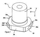
本発明は、冶金容器、例えばタンディッシュ内に含まれる溶融金属の鋳造用の内部ノズルに関する。鋳造方向は鉛直方向を定義する。内部ノズルは、金属ケーシングで部分的に被覆された耐火コアを含む。耐火コアは、貫通孔を備えたプレートに取り付けられた中空管状部分を含む。貫通孔は、管状部分の一方の端部からプレートの底部接触面へ延びている。底部接触面は、スライド平面と称される略水平方向の平面に沿って延びている。内部ノズルは、その接触面を下方に向けた状態で、管交換装置の上側部分に鉛直方向に固定される。スライド平面は、管交換装置の下側部分に沿って内部ノズルに対向する鋳造位置にスライドによって移動される交換可能な注入ノズルのスライドプレートと密着接触するようになっている。内部ノズルは、さらに金属ケーシングを含む。金属ケーシングは、内部ノズルプレートの側縁部の少なくとも一部を被覆する。金属ケーシングは支承面を含む。これらの支承面が、管交換装置のフレームの嵌合支持面上に位置するように、少なくとも2つの別個の支承要素30a,30b,30cが配置されている。前記フレームは、さらに、内部ノズル支承要素のクランプ面32a,32b,32cに圧縮力を加えるのに適したクランプ手段を含み、前記クランプ手段は、支承面34a,34b,34cに対向している。本発明によれば、内部ノズルの支承面34a〜c及びクランプ面32a〜cは金属から形成されているので、フレームとクランプ手段と支承要素との間には金属−金属接触だけが存在し、よって、クランプ手段を起因とするいかなる応力集中の発散及び分配を可能にする。
The present invention relates to an internal nozzle for casting molten metal contained in a metallurgical vessel, for example a tundish. The casting direction defines the vertical direction. The inner nozzle includes a refractory core partially covered with a metal casing. The refractory core includes a hollow tubular portion attached to a plate with a through hole. The through hole extends from one end of the tubular portion to the bottom contact surface of the plate. The bottom contact surface extends along a substantially horizontal plane called a slide plane. The internal nozzle is fixed in the vertical direction to the upper part of the pipe changer with its contact surface facing downward. The slide plane is in intimate contact with the slide plate of the replaceable injection nozzle that is moved by the slide along the lower portion of the tube changer to the casting position opposite the internal nozzle. The internal nozzle further includes a metal casing. The metal casing covers at least a part of the side edge of the inner nozzle plate. The metal casing includes a bearing surface. At least two
従って、フレーム上に位置する内部ノズルの表面が耐火材料ではなく金属から形成されることによって、内部ノズルの耐火材料を削減することが提案される。結果として、クランプシステムが内部ノズルを押圧してフレームに押し付けると、金属表面が、クランプ手段によって引き起こされた応力集中を受ける。金属は耐火コアほど脆弱ではないので、亀裂が生じにくく、これは、空気侵入、金属融液漏れのリスクの減少を意味する。従って内部ノズルの耐用寿命を大幅に延ばすことができ、鋳造金属の品質は改善される。支承平面をスライド平面に対して十分に凹ませることによって、耐火材料から形成された底部接触面が、フレーム内の内部ノズルのクランプに影響を及ぼさないようにすることが好ましい。 Therefore, it is proposed to reduce the refractory material of the internal nozzle by forming the surface of the internal nozzle located on the frame from metal instead of refractory material. As a result, when the clamping system presses the inner nozzle against the frame, the metal surface is subjected to stress concentrations caused by the clamping means. Since the metal is not as fragile as the refractory core, it is less prone to cracking, which means a reduced risk of air ingress and metal melt leaks. Therefore, the service life of the internal nozzle can be greatly extended, and the quality of the cast metal is improved. It is preferred that the bottom contact surface formed from the refractory material does not affect the clamping of the internal nozzles in the frame by sufficiently denting the bearing plane relative to the slide plane.
金属ケーシングは、その機能を満足するのに適した金属から形成することができ、好ましくは、鋼又は鋳鉄である。特に、鋳鉄から形成されている場合には、金属ケーシングの厚さは6mm以上であってよい。よって、許容可能な製造コストを維持しながら、比較的複雑なケーシング形状を得ることができる。大抵の場合、金属ケーシングは、第1の内部ノズル耐火コアが摩耗したときに、第2の耐火コアを被覆するために再使用することができる。 The metal casing can be formed from a metal suitable to fulfill its function, preferably steel or cast iron. In particular, when formed from cast iron, the thickness of the metal casing may be 6 mm or more. Thus, a relatively complex casing shape can be obtained while maintaining an acceptable manufacturing cost. In most cases, the metal casing can be reused to coat the second refractory core when the first inner nozzle refractory core is worn.
上記金属支承面は、少なくとも2つの支承要素30a〜cの支承レッジ34a〜cによって形成される。各レッジは、フレーム上に内部ノズルが確実に配置するのに十分な面積を有するべきである。例えば、在来型の内部ノズルの金属ケーシングの厚さは、支承面と考えることはできない。なぜならば、その厚さは2又は3mmを超えることが稀であり、特に新しい注入ノズルを鋳造位置内へスライドさせて、高い剪断応力を発生させるときに、内部ノズルを所定の位置に保持するには不十分だからである。
The metal bearing surface is formed by bearing
本出願において、管交換装置の内部ノズル「クランプシステム」という表現は、内部ノズルの嵌合支承面30a〜cを所定の位置でクランプするように設計された対向支持面80a〜cを有するクランプ要素50a〜cと、支持面上に位置する支承レッジ34a〜cとの組み合わせを意味する。クランプ要素は、支承レッジ34a〜cとは反対側の、支承要素のクランプ面32a〜c上に圧縮力を加える。
In this application, the expression internal clamp “clamping system” of a tube changer refers to a clamping element having opposing support surfaces 80a-c designed to clamp the mating bearing surfaces 30a-c of the internal nozzle in place. The combination of 50a-c and the
内部ノズルは、さらに、下記複数の構成要件を単独で又は組み合わせを含んでもよい。 The internal nozzle may further include a plurality of constituent elements described below alone or in combination.
支承面は、内部ノズルプレートの周面から突出している。「周面」という用語は、底部プレート接触面の周囲から、好ましくは略鉛直方向に延びる表面を意味する。ノズルは少なくとも2つの別個の支承面30a〜cを含む。これらの支承面は、各々、支承レッジ34a〜cを含む。「別個」という用語は,不連続な非隣接表面を意味する。これらは例えば、ギャップ又はリブによって互いに分離することができる。
The bearing surface protrudes from the peripheral surface of the internal nozzle plate. The term “peripheral surface” means a surface extending from the periphery of the bottom plate contact surface, preferably in a substantially vertical direction. The nozzle includes at least two separate bearing surfaces 30a-c. Each of these bearing surfaces includes bearing
支承レッジは、各々長さ及び幅が5mmを上回り、好ましくは10mm以上である。従って、支承レッジは、フレーム上にその鋳造位置で位置するノズルを固定するのに十分な面積を有している。 The support ledges each have a length and width of more than 5 mm, preferably 10 mm or more. Therefore, the bearing ledge has an area sufficient to fix the nozzle located at the casting position on the frame.
ノズルは、3つ、そして3つだけの別個の支承レッジ34a〜cを含んでもよい。このような構造は、内部ノズルに高い安定性を付与し、四脚スタンドよりも安定性が高い、椅子又はテーブル用の周知の三脚スタンドと同様に、クランプ手段によって各支承要素上に均一の圧力が分配される。4つ以上の支承レッジを用いると、これらの整列状態に小さな欠陥がある場合、クランプが不満足なものになるおそれがある。
The nozzle may include three and only three
好ましい実施態様の場合、内部ノズルの鉛直方向の中心長手方向平面を、内部ノズル貫通孔の中心Z軸線を含むものとして定義することができる。3つの支承レッジ34a〜cは、金属ケーシングの周囲に、前記鉛直方向の中心長手方向平面に対して垂直の平面上に、Y字形状を形成して配置されている。このYの基部は、前記長手方向平面内に配置され、Yの両腕は前記平面の各々の側に配置されており、内部ノズル接触面の図心で合流している。好ましくは、Yの両腕は中心平面に関して対称である。支承レッジ34a〜cのY字形配置は、特に良好なノズルクランプ安定性をもたらす一方、クランプシステムの所要空間を限定し、特に簡単なクランプ法を用いる。なお、鋳造オリフィスが接触面又はスライド面の図心に配置された対称内部ノズルの場合、内部ノズルプレートの図心は内部ノズル貫通孔の図心に一致する。他方において、鋳造流路が接触面の図心に配置されていない、例えば長方形の全体形状を有する非対称ノズルの場合、内部ノズル接触面の図心は、貫通孔の図心とは異なる。
In a preferred embodiment, the vertical central longitudinal plane of the internal nozzle can be defined as including the central Z-axis of the internal nozzle through hole. The three
金属ケーシングは、ノズルの管状部分を収容するための開口を備えた主面と、主面の周囲から延びる側縁部とを含む。一般に、主面の周囲は、2つの長手方向縁部と2つの垂直方向縁部とを備えた長方形によって取り囲むことができる。長手方向は、内部ノズルがその鋳造位置でクランプされているときの、装置内のプレート交換方向によって定義される。長手方向縁部及び垂直方向縁部は直角を成して接合することができ、或いはこれらは丸みを帯びた角部又は面取りされた角部によって結合されていてよい。好ましい実施態様の場合、支承レッジ34a〜cは、ケーシングの横方向縁部、すなわち垂直方向縁部、又は垂直方向縁部を長手方向縁部に結合する縁部にのみ設けられている。交換可能な注入ノズルのプレートを内部ノズルのスライド面に押し付ける、管交換装置の下側部分に配置された加圧手段が、一般には長手方向に沿って配置されるため、長手方向に対して横方向で支承レッジ34a〜cを配置することが有利である。加圧手段に対して横方向に支承レッジを配置することによって、内部ノズル及び注入ノズルの2つのスライド面間の界面全体にわたって、より均一な圧縮力分布がもたらされる。
The metal casing includes a main surface with an opening for receiving the tubular portion of the nozzle and a side edge extending from the periphery of the main surface. In general, the circumference of the major surface can be surrounded by a rectangle with two longitudinal edges and two vertical edges. The longitudinal direction is defined by the plate exchange direction in the apparatus when the internal nozzle is clamped in its casting position. The longitudinal edges and the vertical edges can be joined at right angles, or they can be joined by rounded or chamfered corners. In the preferred embodiment, bearing
ノズルは、内部ノズルを管交換装置のフレームの支持面にクランプするための少なくとも2つの支承要素を含む。各々の支承要素30a〜cは金属ケーシングの部分であり、そして
支承レッジ34a〜cと、
支承レッジとは反対側のクランプ面32a〜cと、
を含み、クランプ面32a〜cには、クランプ要素がクランプ力を加えるように意図されている。クランプ面32a〜cは、ケーシングの主面の部分であってもよく、或いは、図1及び2に示されているように主面から分離されていてよい。
The nozzle includes at least two bearing elements for clamping the inner nozzle to the support surface of the frame of the tube changer. Each bearing element 30a-c is part of a metal casing, and bearing
Clamping surfaces 32a-c opposite to the support ledge;
The
支承要素は、好ましくは完全に金属から形成されており、支承レッジ34a〜cとクランプ面32a〜cとの間には金属だけを有する。この実施態様では、金属だけがクランプ応力を支持し、このことは内部ノズルの耐火材料を削減する。或いは、支承レッジの金属面と支承要素のクランプ面とは、耐火材料のような非金属材料によって分離されていてよい。この実施態様では、支承要素の金属層が、クランプ手段と関連する全応力集中を維持し、そして良好な耐圧縮性を有する耐火コアに応力集中をより均一に再分配する。
The bearing element is preferably made entirely of metal, with only metal between the bearing
管交換装置のフレームに内部ノズルをクランプすると、ノズル支承要素は、フレーム支持面及びクランプシステム間に挟持される。 When the inner nozzle is clamped to the frame of the tube changer, the nozzle bearing element is clamped between the frame support surface and the clamping system.
ノズル支承要素の支承レッジ又はクランプ面は平面であってもよい。或いは、これらの構造は、種々形状、例えば傾斜形状、凸面形状、凹面形状、構造化形状、又は溝付き形状を有していてよい。支承レッジ又はクランプ面は、接触面26に対して略平行な平面内で延びていてよい。好ましくは、支承レッジ又はクランプ面は、好ましくは接触面26に対して平行に、同一平面上にある。これらの表面が、幾何学的配置形状、抵抗性、及び厚さなどに関して、これらの機能を発揮するのに適していることが重要である。支承要素30a〜cの幾何学的配置形状は、これらが取り付けられる管交換装置のクランプ要素及び支持面と嵌合されなければならない。支承レッジ又はクランプ面には付加的な要素、例えばファイバ、シール部材、又は圧縮性要素を、当業者に知られた任意の手段(接着、機械的締結、埋め込みなど)によって加えることもできる。
The support ledge or clamping surface of the nozzle support element may be flat. Alternatively, these structures may have various shapes, such as an inclined shape, a convex shape, a concave shape, a structured shape, or a grooved shape. The bearing ledge or clamping surface may extend in a plane substantially parallel to the
本発明は、また、上記内部ノズルのための金属ケーシングに関し、これとともに、金属ケーシングと耐火要素との組立工程を含む上記内部ノズルの製造方法に関する。 The present invention also relates to a metal casing for the internal nozzle, and also to a method for manufacturing the internal nozzle including an assembly step of the metal casing and a refractory element.
本発明は、また、内部ノズルと、冶金容器からの溶融金属を流し込むためのスライド注入ノズルを保持して交換する管交換装置との組立体であって、内部ノズルは金属ケーシングを含み、前記装置は、
ノズルの少なくとも1つの支承面と接触する上側部分を有するフレームと、
内部ノズルのクランプ面を押圧するように配置された、フレームの上側区分に面するクランプシステムとを含み、
内部ノズル支承面は、金属ケーシングに設けられ、少なくとも2つの別個の支承要素30a〜cの支承レッジ34a〜cによって形成される。
The present invention is also an assembly of an internal nozzle and a pipe changer for holding and replacing a slide injection nozzle for pouring molten metal from a metallurgical vessel, the internal nozzle including a metal casing, the apparatus Is
A frame having an upper portion in contact with at least one bearing surface of the nozzle;
A clamping system facing the upper section of the frame, arranged to press the clamping surface of the inner nozzle,
The inner nozzle bearing surface is provided in the metal casing and is formed by bearing
上記のように、フレーム上に位置する内部ノズル表面は、耐火材料ではなく、金属から形成されることが提案される。従って、クランプシステムが、内部ノズルを、フレームに押し付けるために内部ノズルを圧着するとき、上記の全機械的利点を有する金属−金属接触がもたらされる。 As mentioned above, it is proposed that the internal nozzle surface located on the frame be formed from metal rather than refractory material. Thus, when the clamping system crimps the inner nozzle to press the inner nozzle against the frame, a metal-to-metal contact with all the mechanical advantages described above is provided.
以後、鋳造方向に一致する略鉛直方向をZ方向と呼び、そして内部ノズルの貫通孔の中心軸線をZ軸線と呼ぶ。Z軸線は、内部ノズルが管交換装置にその鋳造位置で取り付けられたときにはZ方向に対して平行である。プレート交換方向に一致する長手方向をX方向と呼ぶ。X方向は、Z方向に対して略垂直であり、X軸線は、X方向に対して平行であり、管交換装置の鋳造開口の図心を通過する。 Hereinafter, the substantially vertical direction coinciding with the casting direction is referred to as the Z direction, and the central axis of the through hole of the internal nozzle is referred to as the Z axis. The Z axis is parallel to the Z direction when the internal nozzle is attached to the tube changer at its casting position. The longitudinal direction coinciding with the plate exchange direction is called the X direction. The X direction is substantially perpendicular to the Z direction, and the X axis is parallel to the X direction and passes through the centroid of the casting opening of the pipe changer.
例えば、溶融鋼を流し込むための、連続溶融金属鋳造設備において、スライドノズルを保持して交換する管交換装置10は、冶金容器、例えばタンディッシュ内に含まれる金属を、1つ又は複数の鋳型のような容器に流し込むために使用される。図3及び4に部分的に示された装置10は、冶金容器の下側に、内部ノズル12を挿入するための、冶金容器の底部内の開口と整列した状態で取り付けられている。内部ノズル12は、管交換装置10のフレームに固定され、そして冶金容器の基底部に、例えばセメントで取り付けられている。典型的な管交換装置の側面図を、欧州特許第1289696号の図1に見いだすことができる。内部ノズル12の貫通孔14は、鋳造流路を形成し、装置10は、注入ノズルのスライドプレートを鋳造位置に案内することによって、注入ノズルの軸方向孔が内部ノズルの貫通孔14と流体連通するように配置されている。これを目的として、装置10は、スライドノズルを、入口を通して待機位置から鋳造位置へ案内するための案内手段16を含む。例えば、案内手段は、案内レール16の形態を成すことができる。レール16は、装置10の通路の長手方向縁部に沿って配置され、装置入口から休止位置へそして鋳造位置へ通じている。さらに、注入ノズル鋳造位置において、装置10は、注入ノズルのプレートを、内部ノズル12の接触面に押し付けるためのX方向に対して平行に配置された手段、例えば圧縮ばねを含む。前記手段は、注入ノズルのスライドプレートの2つの長手方向縁部の各々の底面に力を加えることにより、プレートを内部ノズル12の接触面に密着接触するように押し付け、内部ノズルの貫通孔14と注入ノズルの軸方向孔との間の流体密な接合を形成するように配置されている。装置10は、さらに、以下に、詳細に説明する内部ノズルをクランプする手段20を含む。この手段は、内部ノズル12の2つの縁部のクランプ頂面(32a,32b,32c)に力を加えることによって、内部ノズルの対向する支承面(34a,34b,34c)が装置10の支持面に圧着した状態を維持するように配置されている。横方向という用語は、この文脈においては、X方向に対して平行ではなく、又はX方向と交差することを意味する。
For example, in a continuous molten metal casting facility for pouring molten steel, a
内部ノズル12は、金属ケーシング22を含む。この金属ケーシングは、図2及び6から判るように、耐火材料から形成された内部ノズルプレート24の第1接触面(26)以外の全てを覆っている。金属ケーシング22は、耐火要素24を補強し、そして好ましくはセメントを使用してプレートに結合される。耐火プレートは、ノズルが溶融金属に接触する箇所はどこでも、高温度に耐えるために必須である。しかし、その機械特性、特に、剪断抵抗、摩擦抵抗、及び耐摩耗性は、応力集中が存在する箇所ではどこも不十分である。このような理由から、耐火プレートは、機械応力が加えられるが、溶融金属との接触が生じうる箇所から離れている箇所はどこでも、金属ケーシングで被覆されている。金属ケーシングの厚さは約1mm〜6mm超であってよく、金属ケーシングが鋳鉄から形成されている場合には、一般的に、壁はより厚い。接触面26は、注入ノズルのプレートのスライド面と密着接触させなければならないため、金属ケーシングは、内部ノズルの接触面26には設けられていない(図2及び6参照)。いかなる金属融液の漏れが生じた場合も接触面が損傷されて劇的な結果を引き起こすため、接触面を被覆するために金属を使用することはできない。上述のように、内部ノズルの接触面26が、注入ノズルが装置10によって鋳造位置、すなわち内部ノズル12に面する位置に押し動かされると、注入ノズルのスライド面と密着接触させられる。内部ノズル貫通孔14の一方の端部は、接触面26で開口している。
The
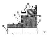
支承レッジ30a,30b,30cは、別個のものであり、内部ノズル12のプレートの周面36から突出している。前記周面36は、プレートの底部接触面26の周囲pmから、好ましくは(しかし必ずしも必要ではない)略鉛直方向Zに突出している。1実施態様の場合、内部ノズルの支承要素の支承レッジとクランプ面との間に、耐火材料が延びていてよい(図6b)。この実施態様では、耐火材料の一部がクランプ手段20の圧縮応力を受けるが、管交換装置のクランプ手段及び支持面から耐火材料を分離する金属層によっていかなる応力集中も吸収されて分配される。好ましい実施態様の場合、支承レッジ及び対向クランプ面は、金属のみによって分離されている(図6a参照)。このことは、クランプ力が耐火材料には全く加えられず、金属のみに加えられる。これらの図面に示された例と同様に、3つの支承レッジ30a,30b,30cは完全に金属から形成されている。すなわち支承面34a,34b,34cとクランプ面32a,32b,32cとの間には金属しかない。
The
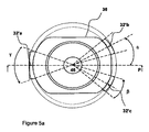
図5及び5(a)から判るように、内部ノズル12は、略長手方向の互いに対向する2つの縁部40a,40bと、これらの長手方向縁部に対して略垂直の互いに対向する2つの縁部42a,42bとを有していてよい。さらに、鉛直方向の中心長手方向平面Pは、X軸線とZ軸線とによって定義することができ、そして3つの支承要素30a,30b,30cは、ノズル12の周囲36上にY字形に配置されていてよく、Yの基部44aは、X軸線と同軸的に中心長手方向平面P内に配置されており、そしてYの2つの腕44b,44cは、前記平面Pの各々の側に配置されており、Yの全ての腕は、(対称的な内部ノズルを想定すると)内部ノズルの貫通孔14の図心46で合流する。より具体的には、第2の支承要素30b及び第3の支承要素30cは、第2支承レッジ34b及び第3支承レッジ34cを有し、これら第2支承レッジ34b及び第3支承レッジ34cの各々は、長手方向平面Pの各々の側に配置されている。記載例では、第2及び第3支承レッジは、対称に配置されているが、このことは必ずしも必要ではない。さらに、接触面26に対して平行な平面上への支承レッジ34b,34cの直交投影の各々は、鋳造オリフィス28の中心に一致する内部ノズル12の図心46を基準として、長手方向平面Pに関して30〜45°の角度α(アルファ)を成して位置決めされた図心32’b,32’cを有する。さらに、第2支承レッジ34b及び第3支承レッジ34cの各々は、内部ノズル12の中心46を基準として10〜20°の角度の区域β(ベータ)内に含まれる。さらに、第1支承要素30aは、ノズル12の長手方向平面Pを通る第1支承レッジ34aを有する。より具体的には、支承レッジ34aは、平面Pに関して略対称に延びており、この面の図心32’aは、内部ノズルの中心46を基準として、14〜52°の角度の区域γ(ガンマ)内に含まれた面内に延びていてよい。
As can be seen from FIGS. 5 and 5 (a), the
図示の実施態様において、支承要素30a,30b,30c、従って、支承レッジ34a,34b,34cは、前記ケーシングの横方向縁部42a,42b上にのみ設けられている。なお、図5及び5aに示されるような概略長方形形状を有する内部ノズルの場合、中心長手方向平面は、外接する長方形の2短辺の中線を含む底部接触面26に対して垂直な平面である。
In the embodiment shown, the
管交換装置のクランプ手段20は、好ましくは、X軸線に対して横方向に配置された2つのクランプ要素を含む。好ましくは、3つのクランプ要素50a,50b,50cが、Y字形を成して内部ノズル12の周囲に配置される(図3参照)。すなわち、Yの基部に位置する第1クランプ要素50aが、中心長手方向平面Pの後ろ部分に配置されており、Yの両腕の端部に位置する第2クランプ要素50b及び第3クランプ要素50cが、前記平面Pの前部分の各々の側に配置されている。図面から判るように、クランプ手段は、内部ノズルの横方向縁部42a,42bに、その力を加えるように配置される。クランプ要素50a,50b,50cは、支承要素30a,30b,30cの相補的な形態を有する。こうして、第1クランプ要素50a、第2クランプ要素50b、及び第3クランプ要素50cは、各々、上記支承レッジ34a,34b,34cにクランプ力Fを加える(図6参照)。クランプ要素50a,50b,50cは、休止位置とクランプ位置との間に移動可能に取り付けられている。クランプ位置において、クランプ要素50a,50b,50cは、支承要素30a,30b,30cのクランプ面32a,32b,32cと接触して、これらの面を押圧することによってクランプ力を加える。これを目的として、クランプ要素50a,50b,50cは、クランプ要素50a,50b,50cと接触するカムとして作用する回転装置によって作動させることができる。任意選択的には、クランプ要素50a,50b,50cのうちの1つ又は複数がコネクティングロッドによって作動させられる。
The clamping means 20 of the tube changer preferably comprises two clamping elements arranged transverse to the X axis. Preferably, three clamping
図3及び4から判るように、内部ノズル12は管交換装置10に結合されている。支承レッジ34a,34b,34cは、フレーム31に設けられた対応支持面80a,80b,80cに配置されている。支承要素30a,30b,30cは、このように、フレームのクランプ要素50a,50b,50cと支持面80a,80b,80cとの間に挟持されている。面34a,34b,34cによって形成された支承面Paが、好ましくは、スライド平面Pgを基準として鉛直方向に凹んでいることにより、注入ノズルのスライド平面との密着接触を確立するのに適した位置で、スライド平面が最前列にくるように露出させている。この例において、支承レッジ34a,34b,34cは、支承要素の底面であり、クランプシステムは、支承要素の上側クランプ面32a,32b,32cに、特に、下方向に力を加える。しかしながら、支承レッジ及びクランプ面を反転させて、クランプシステムは、特に、上向きの力を加えるようにしてもよい。従って内部ノズルは、特に上向きの力によって上方向にクランプされることになる。この実施態様においても、支承要素30a,30b,30cは、クランプ要素と支持面との間に挟持されていてよい。
As can be seen from FIGS. 3 and 4, the
図6に示されているように、支承要素は、好ましくはプレート周囲から延びる金属支承突起の形態を成す。金属支承突起は、支承レッジと、管交換装置の内部ノズル受容部分内のクランプ手段を受け止めるのに適した対向するクランプ面とを含む。図6(b)に示された一実施態様の場合、支承突起の支承レッジが、2つの金属層間に挟持された耐火材料によって、対向するクランプ面から分離されている。支承レッジ及びクランプ面の金属層は、管交換装置のクランプ手段及び支持面から圧縮応力を吸収し、そしてこれを中間耐火部分に均一に分配し、全ての応力集中を吸収して減衰する。同様に、注入ノズルの交換時に、内部ノズルの接触面に大きい剪断応力が加えられ、これらの剪断応力は金属層によって吸収される。 As shown in FIG. 6, the bearing element is preferably in the form of a metal bearing projection extending from the periphery of the plate. The metal bearing projection includes a bearing ledge and an opposing clamping surface suitable for receiving clamping means in the inner nozzle receiving portion of the tube changer. In one embodiment shown in FIG. 6 (b), the bearing ledge of the bearing protrusion is separated from the opposing clamping surfaces by a refractory material sandwiched between two metal layers. The metal layer on the bearing ledge and clamping surface absorbs the compressive stress from the clamping means and support surface of the tube changer and distributes it evenly to the intermediate refractory part, absorbing and damaging all stress concentrations. Similarly, during replacement of the injection nozzle, large shear stresses are applied to the contact surface of the internal nozzle, and these shear stresses are absorbed by the metal layer.
図6(a)に示された別の実施態様では、支承突起の支承レッジは、金属のみによって、対向するクランプ面から分離されてよい。この実施態様の場合、内部ノズルのクランプによって生成された全ての圧縮応力は金属によって支承され、耐火材料は、これらの応力のうちのいかなるものによっても全く影響を及ぼされない。この実施態様によって、耐火材料の耐用寿命は大幅に延長される。 In another embodiment shown in FIG. 6 (a), the bearing ledge of the bearing protrusion may be separated from the opposing clamping surface by metal alone. In this embodiment, all compressive stresses generated by the internal nozzle clamp are carried by the metal and the refractory material is not affected at all by any of these stresses. This embodiment greatly extends the useful life of the refractory material.
上記管交換装置10と共に使用されるノズル12の利点の中で注目すべきことは、金属から形成され、金属ケーシングの部分である支承レッジ34a,34b,34cは、これらが耐火材料24から形成された場合よりも摩耗するのが遅くなり、また、応力集中効果を受けて亀裂形成又は崩壊しにくくなることである。
Of note among the advantages of the
特に、本発明はプレート保持交換装置、例えば管交換装置又は較正プレート交換装置の内部ノズルに関する。本発明によるノズルは、例えば、2つ又はそれ以上のプレートを含むカセットをスライドさせることにより、冶金容器の鋳造オリフィスに対向するようにスライドして移動させるプレート保持交換装置に使用することもできる。 In particular, the present invention relates to an internal nozzle of a plate holding and changing device, such as a tube changing device or a calibration plate changing device. The nozzle according to the present invention can also be used in a plate holding and exchanging device that slides and moves so as to face the casting orifice of a metallurgical vessel, for example, by sliding a cassette containing two or more plates.
本発明の別の利点は、同じ冶金ケーシング22を再び使用して、第2の耐火要素24を被覆できることである。
Another advantage of the present invention is that the same
内部ノズルは、使用前に組み立てられた複数の耐火要素から構成されるようにしてもよい。特に、ノズルプレートとその管状部分とは、2つの別個の要素であってよい。 The internal nozzle may be composed of a plurality of refractory elements assembled prior to use. In particular, the nozzle plate and its tubular part may be two separate elements.
10 プレート保持交換装置
12 内部ノズル
16 案内手段
20 クランプシステム
22 金属ケーシング
26 底部接触面
28 流出開口
30a,30b,30c 支承要素
31 フレーム
32a,32b,32c クランプ面
34a,34b,34c 支承面(支承レッジ)
36 周面
40a,40b 長手方向縁部
42a,42b 横方向縁部
80a,80b,80c 装置の支持面
Pa 支承平面
Pg スライド平面
X プレート交換方向
Y 横方向
Z 鋳造方向
DESCRIPTION OF
36
Claims (14)
該内部ノズルは、
a) 流入開口(14)と流出開口(28)とを流体接続する、第1方向(Z)を定義する軸方向貫通孔を有する管状部分(24)を含み、
該内部ノズルはさらに
b) 平坦な底部接触面(26)を有する内部ノズルプレートを含み、前記底部接触面(26)は前記第1方向(Z)に対して垂直であり、前記接触面は、前記流出開口(28)を含み、
前記内部ノズルプレートは、さらに、前記管状部分(24)の壁を前記プレートの側縁部(40a−b,42a−b)に接合する、前記底部接触面(26)とは反対側の第2面を含み、前記側縁部は、前記底部接触面(26)から前記第2面へ延び、前記プレートの周囲及び厚さを定義しており、
該内部ノズルは、さらに
c) 前記内部ノズルプレートの前記側縁部(40a−b,42a−b)及び第2面のいくつか又は全てのうちの少なくとも一部を被覆するが、底部接触面(26)を被覆しない金属ケーシング(22)を含み、
前記金属ケーシング(22)は
d) 金属支承面(34a,34b,34c)を含み、
前記金属支承面は、前記底部接触面(26)に面しており、且つ前記底部接触面(26)に対して凹んでおり、そして前記側縁部(40a−b,42a−b)の被覆部分から延びている内部ノズルであって、
前記支承面(34a,34b,34c)が、前記プレートの周囲に配置された少なくとも2つの別個の支承要素(30a,30b,30c)の支承レッジによって形成される、ことを特徴とする、冶金容器からの溶融金属の流し込み用内部ノズル。 An internal nozzle (12) for pouring molten metal from a metallurgical vessel,
The internal nozzle is
a) a tubular portion (24) having an axial through hole defining a first direction (Z), fluidly connecting the inflow opening (14) and the outflow opening (28);
Internal nozzle includes an internal nozzle plate having a further b) Tan Taira bottom contact surface (26), said bottom contact surface (26) is perpendicular to the first direction (Z), said contact surface Said outlet opening (28),
The inner nozzle plate further includes a second side opposite the bottom contact surface (26) that joins the wall of the tubular portion (24) to the side edges (40a-b, 42a-b) of the plate. A side edge extending from the bottom contact surface (26) to the second surface and defining a perimeter and thickness of the plate;
The inner nozzle further c) covers at least part of the side edges (40a-b, 42a-b) and some or all of the second surface of the inner nozzle plate, but the bottom contact surface ( 26) a metal casing (22) that does not cover
The metal casing (22) includes d) metal bearing surfaces (34a, 34b, 34c),
The metal bearing surfaces, the faces on the bottom contact surface (26), and wherein is recessed with respect to the bottom contact surface (26), and front SL side edge of (40a-b, 42a-b ) An internal nozzle extending from the covering portion,
Metallurgical vessel characterized in that the bearing surface (34a, 34b, 34c) is formed by a bearing ledge of at least two separate bearing elements (30a, 30b, 30c) arranged around the plate Internal nozzle for pouring molten metal from.
a) X頂点と称される第1頂点を通る、X高さと称される前記三角形の第1高さが、第1軸線(X)に対して平行である幾何学的形状;
b) X頂点を通る、X中線と称される前記三角形の第1中線が、前記第1軸線(X)に対して平行である幾何学的形状;
c) X高さ又はX中線がノズル貫通孔の中心軸線(Z)と、前記貫通孔の図心(46)で交差するような三角形;
d) 前記三角形の角度全てが鋭角である幾何学的形状;
e) 前記三角形が二等辺三角形である幾何学的形状;
f) 貫通孔の中心(46)、及びX頂点以外の三角形の2つの頂点によって形成された角度2αが60〜90°を成す、(c)に基づく三角形;
g) X頂点によって形成される角度が60°未満である三角形、
のうちの1つ又は任意の組み合わせによって形成される、請求項3に記載のノズル。 The triangle formed by the centroids of the projections of the three bearing ledges has the following geometric shape:
a) a geometric shape through which the first height of the triangle, referred to as X height, passes through the first vertex, referred to as X vertex, is parallel to the first axis (X);
b) a geometric shape through which the first midline of the triangle, called the X midline, passing through the X vertex is parallel to the first axis (X);
c) A triangle such that the X height or X midline intersects the central axis (Z) of the nozzle through hole at the centroid (46) of the through hole;
d) a geometric shape in which all the angles of the triangle are acute angles;
e) a geometric shape wherein the triangle is an isosceles triangle;
f) the triangle according to (c), wherein the angle 2α formed by the center of the through hole (46) and the two vertices of the triangle other than the X vertex forms 60-90 °;
g) a triangle whose angle formed by the X vertices is less than 60 °,
4. A nozzle according to claim 3, formed by one or any combination of:
1つの支承面(34a)が、14〜52°の角度の区域γにわたって延び、
他の2つの支承面(34b、34c)が、10〜20°の角度の区域βにわたって延びており、
全ての角度は、前記貫通孔の図心(46)に対して測定されたものである、
請求項4に記載のノズル。 The triangle formed by the centroids of the projections of the three support ledges is such that c) the X height or X center line intersects the central axis (Z) of the nozzle through hole and the centroid (46) of the through hole. A triangle like
One bearing surface (34a) extends over a zone γ with an angle of 14-52 °,
The other two bearing surfaces (34b, 34c) extend over a zone β with an angle of 10-20 °,
All angles are measured with respect to the centroid (46) of the through hole,
The nozzle according to claim 4 .
前記支承レッジの外側尾根部が、前記第1軸線(X)と垂直に交差する接線を有している、請求項4に記載のノズル。 The triangle formed by the centroids of the projections of the three support ledges is such that c) the X height or X center line intersects the central axis (Z) of the nozzle through hole and the centroid (46) of the through hole. A triangle like
The nozzle according to claim 4 , wherein an outer ridge portion of the bearing ledge has a tangent line perpendicularly intersecting the first axis (X).
前記少なくとも2つの支承要素(30a,30b,30c)のうちのどれもが、前記ケーシングの前記長手方向縁部に設けられていない、請求項1から6までのいずれか1項に記載のノズル。 The metal casing (22) includes two pairs of opposing edges (40a, 42a, 40b, 42b) consisting of two longitudinal edges (40a, 40b) and two lateral edges (42a, 42b). ,
The nozzle according to any one of the preceding claims, wherein none of the at least two bearing elements (30a, 30b, 30c) is provided at the longitudinal edge of the casing.
前記支承面(34a,34b,34c)は、前記ケーシングの周囲に配置された少なくとも2つの別個の支承要素(30a,30b,30c)の前記支承レッジによって形成されていることを特徴とする、金属ケーシング。 12. The inner nozzle according to claim 1, wherein the inner nozzle covers at least a part of some or all of the second surface and side edges (40 a-b, 42 a-b) of the nozzle plate. A metal casing (22) comprising: a first main surface having an opening for accommodating a tubular portion of the nozzle; and a side edge extending from the periphery of the first main surface, the side edge The part is a metal casing supporting the bearing surfaces (34a, 34b, 34c),
Metal, characterized in that the bearing surface (34a, 34b, 34c) is formed by the bearing ledge of at least two separate bearing elements (30a, 30b, 30c) arranged around the casing casing.
前記内部ノズルは支承面(34a,34b,34c)を含み、そして前記装置は、鋳造開口を備えたフレーム(31)と、クランプシステム(20)とを含み、
前記鋳造開口を備えたフレーム(31)は、前記鋳造開口の周囲に隣接する支持面(80a,80b,80c)を含み、前記支持面は、前記内部ノズル(12)の支承面(34a,34b,34c)を受容してこれと接触するのに適しており、
前記クランプ・システム(20)は前記支持面(80a,80b,80c)に面しており、そしてクランプ面と称される、前記内部ノズルの支承面(34a,34b,34c)とは反対側の面(32a,32b,32c)を押圧するように配置されている
組立体であって、
前記内部ノズル(12)の支承面(34a,34b,34c)が金属である、
ことを特徴とする、組立体。 An assembly of the internal nozzle (12) according to any one of claims 1 to 11 and a tube exchange device (10) for holding and replacing a slide injection nozzle for pouring molten metal from a metallurgical vessel. And
The internal nozzle includes bearing surfaces (34a, 34b, 34c) and the device includes a frame (31) with a casting opening and a clamping system (20);
The frame (31) having the casting opening includes a support surface (80a, 80b, 80c) adjacent to the periphery of the casting opening, and the support surface is a bearing surface (34a, 34b) of the inner nozzle (12). , 34c) is suitable for receiving and contacting it,
The clamping system (20) faces the support surface (80a, 80b, 80c) and is opposite the bearing surface (34a, 34b, 34c) of the inner nozzle, referred to as the clamping surface. An assembly arranged to press the surfaces (32a, 32b, 32c),
The bearing surfaces (34a, 34b, 34c) of the inner nozzle (12) are metal.
An assembly characterized by that.
Applications Claiming Priority (3)
| Application Number | Priority Date | Filing Date | Title |
|---|---|---|---|
| EP10157127A EP2371471A1 (en) | 2010-03-19 | 2010-03-19 | Internal nozzle for transferring liquid metal contained in a container, system for clamping said nozzle and pouring device |
| EP10157127.1 | 2010-03-19 | ||
| PCT/EP2011/001325 WO2011113598A1 (en) | 2010-03-19 | 2011-03-17 | Inner nozzle for transferring molten metal contained in a metallurgical vessel and device for transferring molten metal |
Publications (2)
| Publication Number | Publication Date |
|---|---|
| JP2013522051A JP2013522051A (en) | 2013-06-13 |
| JP5977226B2 true JP5977226B2 (en) | 2016-08-24 |
Family
ID=42341703
Family Applications (1)
| Application Number | Title | Priority Date | Filing Date |
|---|---|---|---|
| JP2013500369A Active JP5977226B2 (en) | 2010-03-19 | 2011-03-17 | Internal nozzle for pouring molten metal contained in metallurgical vessel and molten metal pouring device |
Country Status (24)
| Country | Link |
|---|---|
| US (1) | US8973790B2 (en) |
| EP (2) | EP2371471A1 (en) |
| JP (1) | JP5977226B2 (en) |
| KR (1) | KR101725579B1 (en) |
| CN (2) | CN102189249B (en) |
| AR (1) | AR080695A1 (en) |
| AU (1) | AU2011229488B2 (en) |
| BR (1) | BR112012022124B1 (en) |
| CA (1) | CA2790272C (en) |
| CL (1) | CL2012002393A1 (en) |
| CU (1) | CU24104B1 (en) |
| ES (1) | ES2522547T5 (en) |
| HR (1) | HRP20141022T4 (en) |
| MA (1) | MA34154B1 (en) |
| MX (1) | MX343214B (en) |
| MY (1) | MY156598A (en) |
| NZ (1) | NZ602092A (en) |
| PL (1) | PL2547476T5 (en) |
| RS (1) | RS53572B2 (en) |
| RU (1) | RU2562870C2 (en) |
| SI (2) | SI2547476T1 (en) |
| TW (1) | TWI533955B (en) |
| UA (1) | UA108634C2 (en) |
| WO (1) | WO2011113598A1 (en) |
Families Citing this family (6)
| Publication number | Priority date | Publication date | Assignee | Title |
|---|---|---|---|---|
| EP2386368A1 (en) * | 2010-03-19 | 2011-11-16 | Vesuvius Group S.A | Internal nozzle for transferring liquid metal contained in a container, system for clamping said nozzle and pouring device |
| CN104249210A (en) * | 2013-06-28 | 2014-12-31 | 鸿富锦精密工业(深圳)有限公司 | Multi-point welding jig |
| ES2658045T3 (en) * | 2013-10-14 | 2018-03-08 | Vesuvius Group (Sa) | Coupling device for reversibly coupling a spoon cover to a collecting nozzle, self-sustaining spoon cover, associated kit and method for attaching a spoon cover to a collecting nozzle |
| CN109877307B (en) | 2017-11-10 | 2021-11-02 | 维苏威集团有限公司 | Self-locking type inner pipe orifice system |
| CN108372580B (en) * | 2018-02-13 | 2020-10-02 | 马鞍山市益江高温陶瓷制造有限公司 | Manufacturing mold for long nozzle |
| CN110238376A (en) * | 2019-06-28 | 2019-09-17 | 维苏威高级陶瓷(中国)有限公司 | The lower plate structure and its manufacturing method of a kind of Zhong Bao sliding plate flow-control mechanism |
Family Cites Families (18)
| Publication number | Priority date | Publication date | Assignee | Title |
|---|---|---|---|---|
| EP0128969B1 (en) * | 1983-06-18 | 1986-10-01 | Vickers Systems GmbH | Double pump |
| BE901564A (en) * | 1985-01-24 | 1985-07-24 | Szadkowski Stanislav | DEVICE FOR FEEDING AND EXCHANGING A CASTING TUBE. |
| SU1488126A1 (en) * | 1987-07-08 | 1989-06-23 | И.А. Кривцов и М.И. Кривцов | Arrangement for pouring molten metal from ladle |
| US5211857A (en) * | 1990-10-31 | 1993-05-18 | Leco Corporation | Gate safety arrangement |
| BE1004092A3 (en) † | 1990-12-19 | 1992-09-22 | Internat Ind Engineering S A | Feed device and exchange tube casting. |
| ES2132782T3 (en) * | 1995-02-17 | 1999-08-16 | Stopinc Ag | SLIDING CLOSURE SYSTEM FOR A TANK CONTAINING CAST METAL. |
| JPH10211570A (en) * | 1997-01-28 | 1998-08-11 | Toshiba Ceramics Co Ltd | Device for supporting pouring nozzle in vessel for casting |
| JPH11188462A (en) † | 1997-12-25 | 1999-07-13 | Toshiba Ceramics Co Ltd | Tundish nozzle exchanging device |
| JPH11207457A (en) * | 1998-01-23 | 1999-08-03 | Toshiba Ceramics Co Ltd | Upper nozzle for sliding gate |
| BE1013024A3 (en) | 1998-12-15 | 2001-08-07 | Internat Ind Engineering S A | Casting tube |
| EP1142660A1 (en) * | 2000-03-07 | 2001-10-10 | Vesuvius Crucible Company | Grooved refractory part used for metallurgical casting, assembly of refractory parts and casting installation comprising such assembly |
| TW553788B (en) * | 2000-04-21 | 2003-09-21 | Vesuvius Crucible Co | One-piece inner nozzle and clamping device for an inner nozzle |
| AR028542A1 (en) * | 2000-04-28 | 2003-05-14 | Vesuvius Crucible Co | REFRACTORY COMPONENT AND ASSEMBLY WITH HERMETIC OBTURATION FOR INJECTION OF AN INERT GAS |
| JP4535594B2 (en) * | 2000-10-13 | 2010-09-01 | 黒崎播磨株式会社 | Immersion nozzle changer for continuous casting machine |
| EP1439016A1 (en) * | 2003-01-20 | 2004-07-21 | Vesuvius Group S.A | Casting tube, clamping device for a casting tube and casting machine |
| EP1454687A1 (en) * | 2003-03-06 | 2004-09-08 | Vesuvius Group S.A | Assembling device of a collector nozzle |
| EP2268432B1 (en) * | 2008-04-17 | 2016-04-13 | Stopinc Aktiengesellschaft | Closing plate and sliding closure on the spout of a receptacle for molten metal |
| CH702467B1 (en) * | 2009-12-21 | 2021-07-15 | Stopinc Ag | Sliding closure for a metallurgical container. |
-
2010
- 2010-03-19 EP EP10157127A patent/EP2371471A1/en not_active Withdrawn
-
2011
- 2011-03-17 RU RU2012136886/02A patent/RU2562870C2/en active
- 2011-03-17 UA UAA201210224A patent/UA108634C2/en unknown
- 2011-03-17 EP EP11710132.9A patent/EP2547476B2/en active Active
- 2011-03-17 CU CU2012000132A patent/CU24104B1/en active IP Right Grant
- 2011-03-17 SI SI201130263T patent/SI2547476T1/en unknown
- 2011-03-17 CA CA2790272A patent/CA2790272C/en active Active
- 2011-03-17 BR BR112012022124-8A patent/BR112012022124B1/en active IP Right Grant
- 2011-03-17 PL PL11710132T patent/PL2547476T5/en unknown
- 2011-03-17 SI SI201130263A patent/SI2547476T2/en unknown
- 2011-03-17 RS RS20140520A patent/RS53572B2/en unknown
- 2011-03-17 US US13/635,921 patent/US8973790B2/en active Active
- 2011-03-17 MX MX2012010797A patent/MX343214B/en active IP Right Grant
- 2011-03-17 MA MA35301A patent/MA34154B1/en unknown
- 2011-03-17 WO PCT/EP2011/001325 patent/WO2011113598A1/en active Application Filing
- 2011-03-17 MY MYPI2012003885A patent/MY156598A/en unknown
- 2011-03-17 ES ES11710132.9T patent/ES2522547T5/en active Active
- 2011-03-17 NZ NZ602092A patent/NZ602092A/en unknown
- 2011-03-17 JP JP2013500369A patent/JP5977226B2/en active Active
- 2011-03-17 KR KR1020127027098A patent/KR101725579B1/en active IP Right Grant
- 2011-03-17 AU AU2011229488A patent/AU2011229488B2/en active Active
- 2011-03-18 TW TW100109327A patent/TWI533955B/en active
- 2011-03-18 AR ARP110100902A patent/AR080695A1/en active IP Right Grant
- 2011-03-21 CN CN201110067877.9A patent/CN102189249B/en active Active
- 2011-03-21 CN CN201120075321XU patent/CN202151692U/en not_active Expired - Lifetime
-
2012
- 2012-08-30 CL CL2012002393A patent/CL2012002393A1/en unknown
-
2014
- 2014-10-23 HR HRP20141022TT patent/HRP20141022T4/en unknown
Also Published As
Similar Documents
| Publication | Publication Date | Title |
|---|---|---|
| JP5977226B2 (en) | Internal nozzle for pouring molten metal contained in metallurgical vessel and molten metal pouring device | |
| KR101790810B1 (en) | Inner nozzle for transferring molten metal contained in a vessel, system for clamping said nozzle and casting device | |
| JP2013522052A5 (en) | ||
| KR20140023966A (en) | Chop gate and nozzle | |
| WO2009087884A1 (en) | Dipped nozzle supporting-replacing mechanism, and lower-nozzle/dipped-nozzle sealing method | |
| JP6951345B2 (en) | Sliding gate valve plate | |
| JP7332314B2 (en) | Sliding nozzle plate and method of reusing the metal strip of the sliding nozzle plate | |
| UA112868C2 (en) | APPLIANCES FOR MOUNTING THE PERFORATED UNIT AND THE PERFORATED UNIT | |
| KR101360691B1 (en) | twin roll strip caster |
Legal Events
| Date | Code | Title | Description |
|---|---|---|---|
| A621 | Written request for application examination |
Free format text: JAPANESE INTERMEDIATE CODE: A621 Effective date: 20140124 |
|
| A977 | Report on retrieval |
Free format text: JAPANESE INTERMEDIATE CODE: A971007 Effective date: 20150212 |
|
| A131 | Notification of reasons for refusal |
Free format text: JAPANESE INTERMEDIATE CODE: A131 Effective date: 20150331 |
|
| A601 | Written request for extension of time |
Free format text: JAPANESE INTERMEDIATE CODE: A601 Effective date: 20150612 |
|
| A521 | Request for written amendment filed |
Free format text: JAPANESE INTERMEDIATE CODE: A523 Effective date: 20150930 |
|
| A131 | Notification of reasons for refusal |
Free format text: JAPANESE INTERMEDIATE CODE: A131 Effective date: 20160308 |
|
| A521 | Request for written amendment filed |
Free format text: JAPANESE INTERMEDIATE CODE: A523 Effective date: 20160511 |
|
| TRDD | Decision of grant or rejection written | ||
| A01 | Written decision to grant a patent or to grant a registration (utility model) |
Free format text: JAPANESE INTERMEDIATE CODE: A01 Effective date: 20160621 |
|
| A61 | First payment of annual fees (during grant procedure) |
Free format text: JAPANESE INTERMEDIATE CODE: A61 Effective date: 20160721 |
|
| R150 | Certificate of patent or registration of utility model |
Ref document number: 5977226 Country of ref document: JP Free format text: JAPANESE INTERMEDIATE CODE: R150 |
|
| R250 | Receipt of annual fees |
Free format text: JAPANESE INTERMEDIATE CODE: R250 |
|
| R250 | Receipt of annual fees |
Free format text: JAPANESE INTERMEDIATE CODE: R250 |
|
| R250 | Receipt of annual fees |
Free format text: JAPANESE INTERMEDIATE CODE: R250 |
|
| R250 | Receipt of annual fees |
Free format text: JAPANESE INTERMEDIATE CODE: R250 |
|
| R250 | Receipt of annual fees |
Free format text: JAPANESE INTERMEDIATE CODE: R250 |