JP5976366B2 - Progressive power lens and progressive power lens design method - Google Patents
Progressive power lens and progressive power lens design method Download PDFInfo
- Publication number
- JP5976366B2 JP5976366B2 JP2012086221A JP2012086221A JP5976366B2 JP 5976366 B2 JP5976366 B2 JP 5976366B2 JP 2012086221 A JP2012086221 A JP 2012086221A JP 2012086221 A JP2012086221 A JP 2012086221A JP 5976366 B2 JP5976366 B2 JP 5976366B2
- Authority
- JP
- Japan
- Prior art keywords
- lens
- power
- refractive power
- horizontal
- toric
- Prior art date
- Legal status (The legal status is an assumption and is not a legal conclusion. Google has not performed a legal analysis and makes no representation as to the accuracy of the status listed.)
- Active
Links
Images


Classifications
-
- G—PHYSICS
- G02—OPTICS
- G02C—SPECTACLES; SUNGLASSES OR GOGGLES INSOFAR AS THEY HAVE THE SAME FEATURES AS SPECTACLES; CONTACT LENSES
- G02C7/00—Optical parts
- G02C7/02—Lenses; Lens systems ; Methods of designing lenses
- G02C7/06—Lenses; Lens systems ; Methods of designing lenses bifocal; multifocal ; progressive
- G02C7/061—Spectacle lenses with progressively varying focal power
- G02C7/068—Special properties achieved by the combination of the front and back surfaces
-
- G—PHYSICS
- G02—OPTICS
- G02C—SPECTACLES; SUNGLASSES OR GOGGLES INSOFAR AS THEY HAVE THE SAME FEATURES AS SPECTACLES; CONTACT LENSES
- G02C7/00—Optical parts
- G02C7/02—Lenses; Lens systems ; Methods of designing lenses
- G02C7/024—Methods of designing ophthalmic lenses
-
- G—PHYSICS
- G02—OPTICS
- G02C—SPECTACLES; SUNGLASSES OR GOGGLES INSOFAR AS THEY HAVE THE SAME FEATURES AS SPECTACLES; CONTACT LENSES
- G02C7/00—Optical parts
- G02C7/02—Lenses; Lens systems ; Methods of designing lenses
- G02C7/06—Lenses; Lens systems ; Methods of designing lenses bifocal; multifocal ; progressive
- G02C7/061—Spectacle lenses with progressively varying focal power
- G02C7/063—Shape of the progressive surface
Description
本発明は、累進屈折力レンズおよび累進屈折力レンズの設計方法に関する。 The present invention relates to a progressive power lens and a method for designing a progressive power lens.
特許文献1には、遠用部と近用部における像の倍率差を低減し、処方値に対する良好な視力補正と、装用時における歪みの少ない広範囲な有効視野を与える両面非球面型累進屈折力レンズを提供することが記載されている。そのため、特許文献1においては、物体側表面の第1の屈折表面において、遠用度数測定位置F1における横方向の表面屈折力及び縦方向の表面屈折力をそれぞれ、DHf、DVfとし、この第1の屈折表面において、近用度数測定位置N1における横方向の表面屈折力及び縦方向の表面屈折力をそれぞれDHn、DVnとするとき、DHf+DHn<DVf+DVn、かつ、DHn<DVnとなる関係式を満足させると共に、第1の屈折表面のF1及びN1における表面非点収差成分を、眼球側表面の第2の屈折表面にて相殺し、前記第1と第2の屈折表面とを合わせて処方値に基づいた遠用度数と加入度数とを与えることが記載されている。
これらの技術により、性能の向上はされてきているものの、依然として累進屈折力レンズの特性、特にゆれに関して適合できないユーザーもおり、更なる改善が求められている。 Although these techniques have improved the performance, there are still users who cannot adapt to the characteristics of the progressive power lens, particularly the fluctuation, and further improvement is required.
本発明の一態様は、遠用部と近用部とを含む累進屈折力レンズである。この累進屈折力レンズは第1のトーリック面の要素を含む物体側の面と、第1のトーリック面の要素をキャンセルする第2のトーリック面の要素を含む眼球側の面と、を有する。第1のトーリック面の要素は、物体側の面の遠用部に予め定められる遠用部測定基準点における垂直方向の面屈折力OVPf1が、遠用部測定基準点における水平方向の面屈折力OHPf1よりも大きく、かつ、OVPf1が、物体側の面の近用部に予め定められる近用部測定基準点における垂直方向の面屈折力OVPn1以上である。 One embodiment of the present invention is a progressive-power lens including a distance portion and a near portion. The progressive-power lens has an object side surface including a first toric surface element and an eyeball side surface including a second toric surface element that cancels the first toric surface element. The element of the first toric surface is such that the surface refractive power OVPf 1 in the vertical direction at the distance measurement reference point predetermined for the distance portion of the object side surface is the horizontal surface refraction at the distance measurement reference point. It is greater than the force OHPf 1 and OVPf 1 is equal to or greater than the surface refractive power OVPn 1 in the vertical direction at the near portion measurement reference point that is predetermined for the near portion of the object side surface.
この累進屈折力レンズは、遠用部測定基準点におけるメリディオナル方向の面屈折力(パワー)がサジタル方向の面屈折力よりも大きい物体側の面のトーリック面の要素を含む。物体側の面のトーリック面の要素(第1のトーリック面の要素)は、眼球側のトーリック面の要素(第2のトーリック面の要素)によりキャンセルされる。 This progressive-power lens includes a toric surface element on the object side surface where the surface refractive power (power) in the meridional direction at the distance measurement reference point is larger than the surface refractive power in the sagittal direction. The toric surface element (first toric surface element) on the object side surface is canceled by the toric surface element (second toric surface element) on the eyeball side.
これらのトーリック面の要素は乱視矯正を目的とするものではなく、眼(視線)の動きにともなう、累進屈折力レンズを通した像のゆれを抑制するのに効果的である。たとえば、このようなトーリック面の要素は、累進屈折力レンズを通して物体を見る際の視線の動きに対して、視線と物体側の面とのなす角度の変位を抑制できると考えられる。このため、累進屈折力レンズを通して得る像の諸収差を低減でき、像のゆれをさらに抑制できる累進屈折力レンズを提供できる。 These toric surface elements are not intended to correct astigmatism, but are effective in suppressing the fluctuation of the image through the progressive power lens accompanying the movement of the eye (line of sight). For example, it is considered that such a toric surface element can suppress the displacement of the angle between the line of sight and the object side surface with respect to the movement of the line of sight when the object is viewed through the progressive addition lens. Therefore, it is possible to provide a progressive power lens capable of reducing various aberrations of an image obtained through the progressive power lens and further suppressing the image shake.
第1のトーリック面の要素は、OVPn1が、近用部測定基準点における水平方向の面屈折力OHPn1よりも大きいことが望ましい。近用部においても、像のゆれを抑制可能な累進屈折力レンズを提供できる。 As for the element of the first toric surface, OVPn 1 is desirably larger than the surface refractive power OHPn 1 in the horizontal direction at the near portion measurement reference point. Also in the near portion, it is possible to provide a progressive power lens capable of suppressing image fluctuation.
第2のトーリック面の要素の、眼球側の面の遠用部測定基準点に対応する点における垂直方向の面屈折力IVPf1、遠用部測定基準点に対応する点における水平方向の面屈折力IHPf1、眼球側の面の近用部測定基準点に対応する点における垂直方向の面屈折力IVPn1、および近用部測定基準点に対応する点における水平方向の面屈折力IHPn1、OVPf1、OHPf1、OVPn1、およびOHPn1が、以下の条件を満たす。
IVPf1−IHPf1=OVPf1−OHPf1
IVPn1−IHPn1=OVPn1−OHPn1
ただし、乱視処方を含まず、IVPf1、IHPf1、IVPn1およびIHPn1は絶対値である。
The surface refractive power IVPf 1 in the vertical direction at the point corresponding to the distance measurement reference point on the eyeball side surface of the second toric surface element, and the horizontal surface refraction at the point corresponding to the distance measurement reference point Force IHPf 1 , vertical surface power IVPn 1 at a point corresponding to the near-field measurement reference point on the eyeball side surface, and horizontal surface power IHPn 1 at a point corresponding to the near-field measurement reference point, OVPf 1 , OHPf 1 , OVPn 1 , and OHPn 1 satisfy the following conditions.
IVPf 1 −IHPf 1 = OVPf 1 −OHPf 1
IVPn 1 -IHPn 1 = OVPn 1 -OHPn 1
However, astigmatism prescription is not included, and IVPf 1 , IHPf 1 , IVPn 1 and IHPn 1 are absolute values.
この累進屈折力レンズの物体側の面の一例は、垂直方向の面屈折力が水平方向の面屈折力よりも大きく、垂直方向の面屈折力と水平方向の面屈折力との差が一定のトーリック面を含むものである。これにより、物体側の面の設計が簡易になる。 An example of the object side surface of this progressive-power lens is that the vertical surface power is larger than the horizontal surface power, and the difference between the vertical surface power and the horizontal surface power is constant. Includes toric surfaces. This simplifies the design of the object side surface.
本発明の他の態様の1つは、遠用部と近用部とを含む累進屈折力レンズの設計方法であり、以下を含む。
1.第1のトーリック面の要素を含むように物体側の面を設計すること。
2.第1のトーリック面の要素をキャンセルする第2のトーリック面の要素を含むように、眼球側の面を設計すること。
Another aspect of the present invention is a method for designing a progressive-power lens including a distance portion and a near portion, and includes the following.
1. Designing the object-side surface to include elements of the first toric surface;
2. Designing the eyeball-side surface to include a second toric surface element that cancels the first toric surface element.
この第1のトーリック面の要素は、物体側の面の遠用部に予め定められる遠用部測定基準点における垂直方向の面屈折力OVPf1が、遠用部測定基準点における水平方向の面屈折力OHPf1よりも大きく、かつ、OVPf1が、物体側の面の近用部に予め定められる近用部測定基準点における垂直方向の面屈折力OVPn1以上である。 The element of the first toric surface is such that the surface refractive power OVPf 1 in the vertical direction at the distance portion measurement reference point predetermined for the distance portion of the object side surface is the horizontal surface at the distance portion measurement reference point. It is greater than the refractive power OHPf 1 , and OVPf 1 is equal to or greater than the surface refractive power OVPn 1 in the vertical direction at the near portion measurement reference point predetermined for the near portion of the object side surface.
本態様によれば、物体側の面および眼球側の面に、トーリック面の要素を含む累進屈折力レンズを設計できる。これらのトーリック面の要素は、乱視矯正を目的とするものではなく、像のゆれを抑制するのに効果的である。したがって、像のゆれが抑制された累進屈折力レンズを設計できる。 According to this aspect, it is possible to design a progressive addition lens including a toric surface element on the object side surface and the eyeball side surface. These toric surface elements are not intended to correct astigmatism but are effective in suppressing image shake. Therefore, it is possible to design a progressive-power lens in which image fluctuation is suppressed.
本実施形態の説明に用いる主要な用語について説明する。
レンズの「物体側の面」とは、装用者が眼鏡を装用したときに対象物に対向する面を意味する。「外面」「凸面」とも言う。
レンズの「眼球側の面」とは、装用者が眼鏡を装用したときに装用者の眼球に対向する面を意味する。「内面」「凹面」とも言う。
レンズの「遠用部」とは、遠距離の物を見る(遠方視の)ための視野部である。
レンズの「近用部」とは、近距離の物を見る(近方視の)ための、遠用部とは度数(屈折力)が異なる視野部である。
レンズの「中間部」とは、遠用部と近用部とを連続的に屈折力が変化するように連結する領域である。中間視のための部分、累進部、累進帯とも言う。
「物体側の面(眼球側の面)の遠用部」とは、レンズの遠用部に対応する物体側の面(眼球側の面)の領域である。
「物体側の面(眼球側の面)の近用部」とは、レンズの近用部に対応する物体側の面(眼球側の面)の領域である。
「物体側の面(眼球側の面)の中間部」とは、レンズの中間部に対応する物体側の面(眼球側の面)の領域である。
レンズの「上方」とは、使用者が眼鏡を装用したときにおける装用者の頭頂側を意味する。
レンズの「下方」とは、使用者が眼鏡を装用したときにおける装用者のあご側を意味する。
「主注視線」とは、遠方視・中間視・近方視をするときに視野の中心となる物体側の面上の位置を結んだ線である。「主子午線」とも言う。
「主注視線に対応する線」とは、遠方視・中間視・近方視をするときに視野の中心となる眼球側の面上の位置を結んだ線である。
「遠用部測定基準点」とは、レンズの遠用部の度数(透過屈折力)が適用されるレンズの物体側の面における座標を意味する。遠用部測定基準点は遠用部に予め定められ、必要に応じて明示される。なお、「点」となっているが微小な面積を含んでいてもよい。
「近用部測定基準点」とは、レンズの近用部の度数(透過屈折力)が適用されるレンズの物体側の面における座標を意味する。近用部測定基準点は近用部に予め定められ、必要に応じて明示される。なお、「点」となっているが微小な面積を含んでいてもよい。
「遠用部測定基準点に対応する点」とは、遠用部測定基準点を通り物体側の面に垂直な光線と眼球側の面との交点の座標を意味する。
「近用部測定基準点に対応する点」とは、近用部測定基準点を通り物体側の面に垂直な光線と眼球側の面との交点の座標を意味する。
レンズの「垂直方向」とは、遠用部における主注視線の方向を意味する。なお、隠しマークによって示される水平方向に直交する方向としても良い。
レンズの「水平方向」とは、垂直方向に直交する方向を意味する。なお、一般にレンズには水平方向を示す隠しマークが施されている。
Main terms used in the description of the present embodiment will be described.
The “object-side surface” of the lens means a surface that faces the object when the wearer wears spectacles. Also called “outer surface” or “convex surface”.
The “surface on the eyeball side” of the lens means a surface facing the eyeball of the wearer when the wearer wears spectacles. Also called “inner surface” or “concave surface”.
The “distance part” of the lens is a visual field part for viewing an object at a long distance (for far vision).
The “near portion” of the lens is a visual field portion that has a power (refractive power) different from that of the far portion for viewing an object at a short distance (for near vision).
The “intermediate portion” of the lens is a region that connects the distance portion and the near portion so that the refractive power continuously changes. It is also called a part for intermediate vision, a progressive part, and a progressive zone.
The “distance portion of the object side surface (eyeball side surface)” is an area of the object side surface (eyeball side surface) corresponding to the distance portion of the lens.
The “object-side surface (eyeball-side surface) near portion” is an area of the object-side surface (eyeball-side surface) corresponding to the near-field portion of the lens.
The “intermediate part of the object side surface (eyeball side surface)” is an area of the object side surface (eyeball side surface) corresponding to the intermediate part of the lens.
“Upper” of the lens means the top side of the wearer when the user wears spectacles.
“Lower” of the lens means the chin side of the wearer when the user wears glasses.
The “main line of sight” is a line connecting positions on the object-side surface that is the center of the visual field when performing far vision, intermediate vision, or near vision. Also known as the “main meridian”.
The “line corresponding to the main gaze line” is a line connecting positions on the eyeball side surface that is the center of the visual field when performing far vision, intermediate vision, and near vision.
The “distance portion measurement reference point” means coordinates on the object side surface of the lens to which the power (transmission power) of the distance portion of the lens is applied. The distance measurement point is determined in advance in the distance portion, and is specified as necessary. In addition, although it is a "point", it may include a minute area.
The “near part measurement reference point” means coordinates on the object side surface of the lens to which the power (transmission power) of the near part of the lens is applied. The near part measurement reference point is predetermined in the near part and is clearly indicated as necessary. In addition, although it is a "point", it may include a minute area.
The “point corresponding to the distance measurement reference point” means the coordinates of the intersection of the ray passing through the distance measurement reference point and perpendicular to the object-side surface and the eyeball-side surface.
The “point corresponding to the near portion measurement reference point” means the coordinates of the intersection point of the ray passing through the near portion measurement reference point and perpendicular to the object side surface and the eyeball side surface.
The “vertical direction” of the lens means the direction of the main gazing line in the distance portion. The direction orthogonal to the horizontal direction indicated by the hidden mark may be used.
The “horizontal direction” of the lens means a direction orthogonal to the vertical direction. In general, the lens is provided with a hidden mark indicating the horizontal direction.
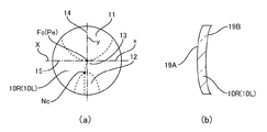
図1は、眼鏡の一例を斜視図にて示している。図2(a)は、本発明の実施形態の1つの累進屈折力レンズの一方のレンズを平面図にて模式的に示している。図2(b)は、その累進屈折力レンズの一方のレンズを断面図にて模式的に示している。 FIG. 1 is a perspective view showing an example of eyeglasses. FIG. 2A schematically shows one lens of one progressive-power lens according to the embodiment of the present invention in a plan view. FIG. 2B schematically shows one of the progressive-power lenses in a cross-sectional view.
本例では、ユーザー側(着用者側、眼球側)から見て、左側を左、右側を右として説明する。この眼鏡1は、左眼用および右眼用の左右一対の眼鏡用レンズ10Lおよび10Rと、レンズ10Lおよび10Rをそれぞれ装着した眼鏡フレーム20とを有する。レンズ10Lおよび10Rは、累進屈折力レンズである。レンズ10Lおよび10Rの基本的な形状は物体側に凸のメニスカスレンズである。したがって、レンズ10Lおよび10Rは、それぞれ、物体側の面19Aと、眼球側の面19Bとを含む。以下においては、右眼用および左眼用の眼鏡用レンズ10Rおよび10Lを共通してレンズ10と称する。
In this example, as viewed from the user side (wearer side, eyeball side), the left side is left and the right side is right. The
図2(a)は右眼用レンズ10Rを示している。レンズ10Rは、上方に遠用部11を含み、下方に近用部12を含む。さらに、レンズ10Rは、中間部(累進部、累進帯)13を含む。また、レンズ10Rは、主注視線14を含む。レンズ10Rをフレーム枠に合わせて外周を成形し枠入れする際に遠方水平正面視(第一眼位)での視線が通過するようにするレンズ上の基準点であるフィッティングポイントPeは遠用部11のほぼ下端に位置するのが通常である。以下においてはこのフィッティングポイントPeをレンズの座標原点とし、水平基準線15(フィッティングポイントPeを通る水平方向の線、X軸)に沿った方向の座標をx座標、垂直基準線(第1の基準線)Y(フィッティングポイントPeを通る垂直方向の線、Y軸)に沿った方向の座標をy座標とする。主注視線14は遠用部11から近用部12方向にほぼ垂直に伸び、フィッティングポイントPeを過ぎたあたりから鼻側に曲がる。なお、本実施形態においては、遠用部測定基準点FcはフィッティングポイントPeに一致するように設定され、近用部測定基準点Ncは、近用部12の上端と主注視線14との交点に一致するように設定される。
FIG. 2A shows the right-
なお、以下においてレンズとして右眼用のレンズ10Rを中心に説明するが、レンズは左眼用のレンズ10Lであってもよく、左眼用のレンズ10Lは、左右の眼の眼鏡仕様の差を除けば基本的には右眼用のレンズ10Rと左右対称の構成となる。
In the following description, the
レンズ10の光学性能のうち視野の広さについては、非点収差分布図や等価球面度数分布図により知ることができる。レンズ10の性能の1つは、レンズ10を着用して頭を動かしたときに感じるゆれ(ユレ、揺れ)であり、非点収差分布や等価球面度数分布がほとんど同じであっても、ゆれに関して差が発生することがある。以下においては、まず、ゆれの評価方法について説明し、その評価方法を用いて、本願の実施形態と、従来例とを比較した結果を示す。
Of the optical performance of the
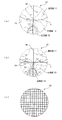
1. ゆれの評価方法
図3(a)に、典型的なレンズ10の等価球面度数分布(単位はディオプトリ(D))を示し、図3(b)に、非点収差分布(単位はディオプトリ(D))を示し、図3(c)に、このレンズ10により正方格子を見たときの歪曲の状態を示している。レンズ10においては、主注視線14に沿って所定の度数が加入される。度数の加入により、中間領域(中間部、累進領域)13の側方には大きな非点収差が発生するので、中間部13の側方では物がぼやけて見えてしまう。等価球面度数分布は近用部12では所定の量だけ遠用部11よりも度数が高く、近用部12から中間部13、遠用部11へと順次度数が減少する。このレンズ10においては、遠用部11の度数(遠用度数、Sph)は0.00D(ディオプトリ)であり、加入度数(ADD)は2.00Dである。
1. FIG. 3A shows an equivalent spherical power distribution (unit is diopter (D)) of a
この度数のレンズ10上の位置による違いにより、度数の大きな近用部12では遠用部11に比べ像の倍率が大きくなり、中間部13から近用部12の側方では、正方格子像はひずんで見える。これが頭を動かしたときの像のゆれ(ユレ)の原因となる。
Due to the difference of the power depending on the position on the
図4に、前庭動眼反射(Vestibulo−Ocular Reflex(VOR))の概要を示している。人はもの(図4では対象物9)を見ているとき頭部が動くと視界も動く。このとき、網膜上の像も動く。頭部の動き(顔の回旋(回転)、頭部の回旋)8を相殺するような眼球3の動き(眼の回旋(回転))7があれば視線2は安定し(動かず)、網膜像は動かない。このような網膜像を安定化させる機能をもつ、反射的な眼球運動を代償性眼球運動という。代償性眼球運動の一つが前庭動眼反射であり、頭部の回旋が刺激となり反射を生じる。水平回旋(水平回転)による前庭動眼反射の神経機構はある程度解明されており、頭部の回旋8を水平半規管が検知し、水平半規管からの入力が外眼筋に抑制性と興奮性の作用を与え、眼球3を動かすと考えられている。
FIG. 4 shows an overview of vestibulo-ocular reflex (VOR). When a person is looking at an object (object 9 in FIG. 4), the field of view moves when the head moves. At this time, the image on the retina also moves. If there is a movement (eye rotation (rotation)) 7 of the eyeball 3 that cancels out the movement of the head (face rotation (rotation), head rotation) 8, the line of
頭部が回旋したとき、前庭動眼反射により眼球が回旋すると網膜像は動かないが、図4に破線および一点鎖線で示したように頭部の回旋に連動してレンズ10が回旋する。このため、前庭動眼反射によりレンズ10を通過する視線2は相対的にレンズ10の上を動く。したがって、前庭動眼反射により眼球3が動く範囲、すなわち、前庭動眼反射により視線2が通過する範囲でレンズ10の結像性能に差があると、網膜像がゆれることがある。
When the head rotates, the retinal image does not move when the eyeball rotates due to the vestibulo-oculomotor reflex, but the
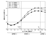
図5は、対象物探索時の頭位(眼位)運動を観察した一例を示すグラフである。横軸は被験者の正面方向と注視点(対象物)とがなす水平方向の角度、縦軸は頭部回転角を示す。図5に示されるグラフは、注視点より水平方向にある角度だけ移動した対象物を認識するために、頭部がどの程度回旋するかを示している。対象物を注目させる注視の状態においては、グラフ41に示すように頭部は対象物とともに回旋する。これに対して、対象物を単に認識する程度の弁別視の状態においては、グラフ42に示すように、頭部の動きは対象物の角度(移動)に対して10度程度小さく(少なく)なる。この観察結果により、眼球の動きにより対象物を認識できる範囲の限界を約10度程度に設定できる。したがって、自然な状態で人間が頭部を動かしながら前庭動眼反射により対象物を見るときの水平方向の頭部の回旋角度は左右にそれぞれ最大10度程度(前庭動眼反射により眼球3が動く最大水平角度θxm)と考えられる。
FIG. 5 is a graph showing an example of observing the head position (eye position) movement when searching for an object. The horizontal axis represents the horizontal angle between the front direction of the subject and the point of interest (object), and the vertical axis represents the head rotation angle. The graph shown in FIG. 5 shows how much the head rotates in order to recognize an object moved by an angle in the horizontal direction from the point of gaze. In a gaze state where attention is paid to the object, the head rotates with the object as shown in the
一方、レンズの場合は、中間部13では度数の変化があるため、前庭動眼反射により対象物9を見る時の垂直方向の頭部の回旋が大きいと、対象物の距離に対して度が合わなくなり、像がぼけてしまう。そのため、前庭動眼反射により対象物9を見る時の垂直方向の頭部の最大回旋角は、水平方向の最大回旋角よりも小さくなることが考えられる。以上から、ゆれのシミュレーションを行う場合のパラメータとなる頭部回旋角は水平方向で左右に約10度程度、垂直方向では水平方向の最大回旋角より小さく、例えば上下に5度程度を用いるのが好ましい。また、前庭動眼反射により視線が動く範囲の典型的な値は、水平方向では、主注視線14の左右±10度程度である。
On the other hand, in the case of a lens, since there is a change in the power at the
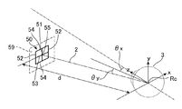
図6に、仮想空間の仮想面59に配置された対象物9に対して頭部を回旋させたときの前庭動眼反射を加味した視覚のシミュレーションを行う様子を示している。図6に示される例では、対象物9は矩形模様50である(図6には対象物9の符号は示していない)。仮想空間に眼球3の回旋中心Rcを原点として、水平正面方向にz軸を設定し、水平方向にx軸、垂直方向にy軸を設定する。x軸、y軸、z軸は互いに直交している。y−z平面に対して角度θx、x−z平面に対して角度θyをなす方向に、距離dを隔てた仮想面59に矩形模様50を配置する。
FIG. 6 shows a state in which a visual simulation is performed in consideration of vestibulo-ocular reflex when the head is rotated with respect to the object 9 arranged on the
図6に示される例においては、矩形模様50は縦横に2等分された正方格子であり、幾何学的中心55を通る中心の垂直格子線51および中心の垂直格子線51に対して左右対称な左右の垂直格子線52と、幾何学的中心55を通る中心の水平格子線53および中心の水平格子線53に対し上下対称な上下の水平格子線54とを含む。この正方格子の矩形模様50を、以下に示すようにピッチ(隣り合う垂直格子線51(水平格子線53)同士の間隔)がレンズ10の上に視野角で設定されるように仮想面59と眼球3との距離dを調整する。なお、ピッチは、回旋中心Rcと幾何学的中心55を結ぶ直線を基準として水平方向または垂直方向の角度(単位°)で表される。
In the example shown in FIG. 6, the
図6に示される例では、レンズ10を実際の装用時と同じ位置・姿勢で眼球3の前に配置し、注視点に対して前庭動眼反射により眼球3が動く最大水平角度θxmの近傍、すなわち、注視点に対して±10度に左右の垂直格子線52および上下の水平格子線54がそれぞれ見えるように仮想面59を設定する。
In the example shown in FIG. 6, the
正方格子の矩形模様50のサイズは視野角で規定することができ、見る対象物に合わせて設定することが可能である。例えばモバイルパソコンの画面などでは格子のピッチは小さく、デスクトップパソコンの画面では格子のピッチは大きくとることができる。
The size of the
一方、仮想面59までの距離dについては、レンズ10の場合は、遠用部11、中間部13、近用部12により想定される対象物9の距離が変わるので、それを考慮して遠用部11では数m以上の遠距離、近用部12では40cmから30cm程度の近距離、中間部13は1mから50cm程度の中間距離にすることが妥当である。ただし、例えば歩行時には中間部13、近用部12でも2mから3mの距離のものが観察対象となるので、あまり厳密にレンズ上の遠・中・近の領域に合わせて距離dを設定する必要はない。
On the other hand, with respect to the distance d to the
レンズ10の屈折作用により矩形模様50は視野方向(θx、θy)からずれた視野角方向に観察される。このときの矩形模様50の観察像は通常の光線追跡法により求めることができる。この状態を基本として、水平方向に+α°頭部を回旋させると顔と一緒にレンズ10も+α°回旋する。このとき前庭動眼反射により眼球3は逆方向にα°、即ち−α°回旋するので、レンズ10の上では視線2は−α°移動した位置を使って矩形模様50の幾何学的中心55を見ることになる。したがって、レンズ10の視線2の透過箇所や視線2のレンズ10への入射角度が変わるので、矩形模様50は実際の形とは違った形で観察される。この形状のずれが像のゆれの要因となる。
The
このため、本項で説明するゆれの評価方法においては、頭部を左右または上下に反復回旋したときの、最大または所定の回旋角度θx1の両端位置における矩形模様50の画像を幾何学的中心55で重ね合わせ、両者の形状のずれを幾何学的に計算する。水平角度θx1の一例は前庭動眼反射により眼球3が動く最大水平角度θxm(約10度)である。
Therefore, in the shake evaluation method described in this section, the image of the
本実施形態でゆれの評価に用いられる指数の1つは振動を示すゆれ指標IDdであり、水平格子線53および54、および垂直格子線51および52の傾きの変化を示す。他の1つは変形量を示すゆれ指標IDsであり、水平格子線53および54、および垂直格子線51および52の移動面積を示す。
One of the indices used for the evaluation of vibration in this embodiment is a vibration index IDd indicating vibration, and indicates changes in the inclination of the
図7は、注視点に対して第1の水平角度(振り角)θx1(10度)で左右に眼球3および矩形模様50を動かしたときの矩形模様50の像の一例を示している。図7に示される状態は、矩形模様50を動かさず、水平角度(振り角)10度でレンズ10を装用して頭部を左右に動かしたときに、視線2が矩形模様50の幾何学的中心55から動かないように矩形模様50を見ている状態に相当する。矩形模様50a(破線)は、振り角10°で光線追跡法によりレンズ10を介して観察される像(右回旋画像)であり、矩形模様50b(実線)は同様に振り角−10°で観察される像(左回旋画像)である。図7においては、矩形模様50aおよび50bを幾何学的中心55が一致するように重ねて示している。なお、振り角0°で観察される矩形模様50の像はこれらのほぼ中間に位置する(図示せず)。振り角を上下に設定した場合に観察される像(上回旋画像及び下回旋画像)も同様に求めることができる。
FIG. 7 shows an example of an image of the
矩形模様50aおよび50bは、レンズ10を通して矩形模様50を見ながら頭を振ったときにユーザーが実際に認識する矩形模様50の像に相当する。矩形模様50aおよび50bの差は、頭を振ったときにユーザーが認識する像の動きを表していると見なすことができる。
The
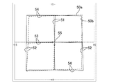
図8は、ゆれ指標(ゆれ指数)IDdを説明する図である。ゆれ指標IDdは、各格子線51〜54の傾きの変化を表す指標である。図8に示すように矩形模様50の垂直格子線51、垂直格子線52、水平格子線53及び水平格子線54の勾配の変化量を幾何学的に計算することにより、ゆれ指数IDdを12個求めることができる。このうち水平方向の格子線(水平格子線)53および54の勾配の変化量は「波打ち(うねり)」を表し、垂直方向の格子線(垂直格子線)51および52の勾配の変化量は「揺らぎ」を表していると考えられる。したがって、水平格子線53及び水平格子線54の勾配の変化量を合算すると「波打ち(うねり)感」としてゆれを定量評価できる。また、垂直格子線51及び垂直格子線52の勾配の変化量を合算すると「揺らぎ感」としてゆれを定量評価できる。
FIG. 8 is a diagram for explaining a swing index (swing index) IDd. The fluctuation index IDd is an index that represents a change in the inclination of each of the
図9および図10は、ゆれ指数IDsを説明する図である。垂直格子線51、垂直格子線52、水平格子線53及び水平格子線54の移動面積を表す指数である。すなわち、ゆれ指数IDsは、矩形模様50の全体形状の変形の大きさに相当する。ゆれ指標IDsは、図9および10に示すように矩形模様50の垂直格子線51、垂直格子線52、水平格子線53及び水平格子線54のそれぞれの移動量を面積として幾何学的に計算することによって、12個の数値を得ることができる。図9は水平格子線53および54の移動量(斜線塗りつぶし部分)を表し、図10は垂直格子線51および52の移動量(斜線塗りつぶし部分)を表した図である。移動量(面積)で表わされるゆれ指標IDsは、ゆれ指標IDdと同様に、垂直格子線51及び垂直格子線52の移動量を合算することで「揺らぎ感」を、水平格子線53及び水平格子線54の移動量を合算することで「波打ち(うねり)感」を定量評価できる。ただし、レンズ10がゆれ評価位置付近で大きな倍率変化を持っていた場合、例えば水平方向に伸び縮みが生ずるような変形がある場合は、それらの要素も包含した指標となる。
9 and 10 are diagrams for explaining the shaking index IDs. This is an index representing the moving area of the
ゆれ指標IDdの単位は、視野角座標上での各格子線の勾配の変化量であるので無次元である。一方、ゆれ指標IDsの単位は、視野角座標上での面積であるので、度(°)の二乗である。なお、ゆれ指数IDsとして、垂直格子線51、垂直格子線52、水平格子線53及び水平格子線54の移動面積を頭部の回旋を加える前(0度)における矩形模様50の面積で割り、比率(たとえば、パーセント)表示した数値を用いることも可能である。
The unit of the swing index IDd is dimensionless since it is the amount of change in the gradient of each grid line on the viewing angle coordinates. On the other hand, the unit of the swing index IDs is an area on the viewing angle coordinates, and is therefore a square of degrees (°). In addition, as the shaking index IDs, the moving area of the
ゆれ指標IDdおよびIDsは、水平方向成分(「波打ち(うねり)感」の指標)、垂直方向成分(「揺らぎ感」の指標)、およびそれらの合算値として、用途により使い分けることができる。以降において、勾配の変化から得られるゆれ指標IDdは「振動」と表現し、格子線の移動量から得られるゆれ指標IDsを「変形量」と表現することがある。 The swing indices IDd and IDs can be properly used as a horizontal direction component (an index of “waviness”), a vertical direction component (an index of “fluctuation”), and a total value thereof. Hereinafter, the fluctuation index IDd obtained from the change in gradient may be expressed as “vibration”, and the fluctuation index IDs obtained from the movement amount of the grid line may be expressed as “deformation amount”.
以降において、振動に関する指標IDdは、中心の水平格子線53を含むすべての水平格子線53および54の勾配の変化量(水平方向成分)と、中心の垂直格子線51を含むすべての垂直格子線51および52の勾配の変化量(垂直方向成分)とを合算または平均した値である。すなわち、以降におけるゆれ視標IDdは、すべての格子線の勾配の変化量の総和または平均である。
In the following, the index IDd relating to vibration is the amount of change in the gradient (horizontal component) of all
実際にユーザーがゆれを感じているときには対象物に含まれるただ1つの水平あるいは垂直の線の変動よりも、形として捉えている対象物の輪郭(おおよその形状)の変動として知覚されているという事実からすると、IDdの水平方向成分および垂直方向成分は、ユーザーの感覚に近い。さらに、ユーザーにおいては水平方向も垂直方向も同時に知覚されるので、それらを合算した値が一番ユーザーの感覚に近い指標と言える。しかしながら、ユーザーによって「波打ち(うねり)」と「揺らぎ」に対する感受性が異なる可能性や、個人の生活環境による視線の使い方が水平方向での視線移動が多い場合には「波打ち(うねり)」を問題としたり、その逆に「揺らぎ」を問題にするケースが考えられる。したがって、各方向成分により、ゆれを指標化し、評価してもよい。 When the user actually feels shaking, it is perceived as a change in the outline (approximate shape) of the target object as a shape rather than a single horizontal or vertical line change in the target object. In fact, the horizontal and vertical components of IDd are close to the user's sense. Furthermore, since the user perceives both the horizontal and vertical directions at the same time, the sum of these values can be said to be the index closest to the user's sense. However, there is a possibility that the susceptibility to “swell” and “fluctuation” differs depending on the user, and “swell (swell)” is a problem when the gaze movement in the horizontal direction is frequently used in the personal life environment. Or, conversely, “fluctuation” is a problem. Therefore, the fluctuation may be indexed and evaluated by each direction component.
以降において、変形量に関する指標IDsは、中心の水平格子線53を含むすべての水平格子線53および54の変動面積と、中心の垂直格子線51を含むすべての垂直格子線51および52の変動面積との合算値である。
Hereinafter, the index IDs relating to the deformation amount is the fluctuation area of all the
変形量による指標IDsのメリットは、倍率の変化が加味される点である。特にレンズ10の場合は垂直方向に度数の加入がされる。このため、首を縦方向に振ってものを見た場合、度数の変化によって像が拡大・縮小されたり、前後に揺動して見えたりする現象がある。また加入度数が大きい場合も近用部の側方で倍率が落ちる現象が顕著になる。このため、像の横方向での伸び縮みが発生する。変形量による指標IDsはこれらの変化を数値化できるので、評価方法として有用である。
The merit of the index IDs based on the deformation amount is that a change in magnification is taken into account. In particular, in the case of the
2. 実施形態1
以下の実施形態のレンズ10の物体側の面(外面)19Aは、遠用部測定基準点Fcにおける垂直方向の面屈折力OVPf1が、遠用部測定基準点Fcにおける水平方向の面屈折力OHPf1よりも大きく、かつ、OVPf1が近用部測定基準点Ncにおける垂直方向の面屈折力OVPn1以上である、第1のトーリック面の要素(物体側の面のトーリック面の要素)TF1を含む。第1のトーリック面の要素TF1は、以下の条件を含む。
OVPf1>OHPf1・・・(1a)
OVPf1≧OVPn1・・・(1b)
2.
The surface (outer surface) 19A on the object side of the
OVPf 1 > OHPf 1 (1a)
OVPf 1 ≧ OVPn 1 (1b)
式(1a)は、遠用部測定基準点Fcがトーリック面(トロイダル面)の要素を含むことを示す。 Equation (1a) indicates that the distance measurement reference point Fc includes a toric surface (toroidal surface) element.
式(1b)は、物体側の面19Aの度数が、少なくとも測定基準点の垂直方向の面屈折力に関して、加入度がゼロか、遠用部11の面屈折力が近用部12の面屈折力よりも大きい逆加入となっていることを示す。
Equation (1b) indicates that the power of the
なお、以下の各実施形態においては、外面19Aは、遠用部11の主注視線14上の任意の点yにおける垂直方向の面屈折力OVPfが、当該点yにおける水平方向の面屈折力OHPfよりも大きく、かつ、OVPfが近用部12上の任意の点xにおける垂直方向の面屈折力OVPn以上である。すなわち、外面19Aは以下の条件を満たす。
OVPf>OHPf・・・(1aa)
OVPf≧OVPn・・・(1ba)
In each of the following embodiments, the
OVPf> OHPf (1aa)
OVPf ≧ OVPn (1ba)
式(1aa)は、主注視線14(に沿った領域)が、トーリック面(トロイダル面)の要素を含むことを示す。 Expression (1aa) indicates that the main gaze line 14 (the area along the line) includes an element of a toric surface (toroidal surface).
式(1ba)は、外面19Aの度数は、少なくとも主注視線14(に沿った領域)の垂直方向の面屈折力に関して、加入度がゼロか、逆加入となっていることを示す。
The expression (1ba) indicates that the power of the
第1のトーリック面の要素TF1は、近用部測定基準点Ncにおける垂直方向の面屈折力OVPn1と水平方向の面屈折力OHPn1とに関する以下の条件を含むことが望ましい。
OVPn1≧OHPn1・・・(1c)
The first toric surface element TF1 of preferably includes the following condition relating to the vertical surface power OVPn 1 and horizontal surface power OHPn 1 Tokyo in the near reference point Nc.
OVPn 1 ≧ OHPn 1 (1c)
外面19Aの近用部測定基準点Ncが、水平方向の面屈折力が垂直方向の面屈折力よりも大きいトーリック面の要素を備えていてもよいが、垂直方向の面屈折力が水平方向の面屈折力よりも大きいトーリック面と水平方向の面屈折力が垂直方向の面屈折力よりも大きいトーリック面とが混在していると、レンズ10を通して物を見たときに像のゆれが拡大する要因になる可能性がある。したがって、近用部測定基準点Ncも垂直方向面屈折力が水平方向の面屈折力よりも大きいトーリック面の要素を含むことが望ましい。このため、第1のトーリック面の要素TF1は、以下の条件をさらに満足することが好ましい。
OVPn1>OHPn1・・・(1c´)
The near portion measurement reference point Nc of the
OVPn 1 > OHPn 1 (1c ′)
なお、以下の実施形態においては、外面19Aは、さらに、以下の条件を満たす面(トーリック面)であることが望ましい。すなわち、外面19Aの近用部12の主注視線14上の任意の点xにおける垂直方向の面屈折力OVPnと、当該点xにおける水平方向の面屈折力OHPnとに関する以下の条件を含むことが望ましい。
OVPn≧OHPn・・・(1ca)
In the following embodiments, the
OVPn ≧ OHPn (1ca)
外面19Aの近用部12が、水平方向の面屈折力が垂直方向の面屈折力よりも大きいトーリック面の要素を備えていてもよいが、垂直方向の面屈折力が水平方向の面屈折力よりも大きいトーリック面と水平方向の面屈折力が垂直方向の面屈折力よりも大きいトーリック面とが混在していると、レンズ10を通して物を見たときに像のゆれが拡大する要因になる可能性がある。したがって、近用部12も垂直方向の面屈折力が水平方向の面屈折力よりも大きいトーリック面の要素を含むことが望ましい。このため、外面19Aのトーリック面は、以下の条件をさらに満足することが好ましい。
OVPn>OHPn・・・(1ca´)
The
OVPn> OHPn (1ca ′)
レンズ10を使用するときの人の視覚の特性として、主注視線14または基準線Y上での使用頻度が極めて大きく、像のゆれを感じるのはその主注視線14近傍を使い視作業をするときである。したがって、上記条件(1aa)、(1ba)および(1ca)に示した外面19Aにおける条件は、少なくとも主注視線14上において成立することが好ましく、主注視線14を中心として水平方向に約10mm以内で成立することがより好ましい。主注視線14を中心として10mm以内で成立すれば、像のゆれを軽減するなどの効果を十分に得ることができる。
As a human visual characteristic when using the
レンズ10の眼球側の面(内面)19Bは、第1のトーリック面の要素TF1による面屈折力のシフトをキャンセルする第2のトーリック面の要素TF2を含む。第2のトーリック面の要素TF2は、遠用部測定基準点Fcに対応する点における垂直方向の面屈折力IVPf1、遠用部測定基準点Fcに対応する点における水平方向の面屈折力IHPf1、近用部測定基準点Ncに対応する点における垂直方向の面屈折力IVPn1、近用部測定基準点Ncに対応する点における水平方向の面屈折力IHPn1について以下の条件を含む。
IVPf1−IHPf1=OVPf1−OHPf1・・・(2a)
IVPn1−IHPn1=OVPn1−OHPn1・・・(2b)
ただし、これらの条件および以下に示す条件は乱視処方を含まない。すなわち、これらの条件は遠用処方における乱視処方は含まない。以下においても同様である。また、面屈折力IVPf1、IHPf1、IVPn1およびIHPn1は絶対値である。
The eyeball side surface (inner surface) 19B of the
IVPf 1 -IHPf 1 = OVPf 1 -OHPf 1 (2a)
IVPn 1 -IHPn 1 = OVPn 1 -OHPn 1 (2b)
However, these conditions and the following conditions do not include astigmatism prescription. That is, these conditions do not include the astigmatism prescription in the distance prescription. The same applies to the following. Further, the surface refractive powers IVPf 1 , IHPf 1 , IVPn 1 and IHPn 1 are absolute values.
なお、以下の実施形態においては、内面19Bは、遠用部11の主注視線14上の任意の点yに対応する点における垂直方向の面屈折力IVPf、当該点yに対応する点における水平方向の面屈折力IHPf、近用部12上の任意の点xに対応する点における垂直方向の面屈折力IVPn、当該点xに対応する点における水平方向の面屈折力IHPnについて以下の条件を含む。
IVPf−IHPf=OVPf−OHPf・・・(2aa)
IVPn−IHPn=OVPn−OHPn・・・(2ba)
ただし、これらの条件および以下に示す条件は乱視処方を含まない。すなわち、これらの条件は遠用処方における乱視処方は含まない。以下においても同様である。また、面屈折力IVPf、IHPf、IVPnおよびIHPnは絶対値である。
In the following embodiment, the
IVPf−IHPf = OVPf−OHPf (2aa)
IVPn-IHPn = OVPn-OHPn (2ba)
However, these conditions and the following conditions do not include astigmatism prescription. That is, these conditions do not include the astigmatism prescription in the distance prescription. The same applies to the following. Further, the surface refractive powers IVPf, IHPf, IVPn, and IHPn are absolute values.
なお、条件(2a)、(2b)、(2aa)および(2ba)はレンズの厚みが薄いと仮定したときの条件式である。レンズの屈折力計算に用いられるレンズの厚みを考慮した式は、形状係数(シェイプファクター)が加味される。たとえば、条件式(2aa)および(2ba)は以下のように記載される。
IVPf−IHPf=
OVPf/(1−t/n×OVPf)−OHPf/(1−t/n×OHPf)
・・・(2aa´)
IVPn−IHPn=
OVPn/(1−t/n×OVPn)−OHPn/(1−t/n×OHPn)
・・・(2ba´)
ここで、tはレンズの厚み(単位はメートル)、nはレンズ素材の屈折率である。
Conditions (2a), (2b), (2aa) and (2ba) are conditional expressions when it is assumed that the lens is thin. The formula that takes into account the thickness of the lens used for calculating the refractive power of the lens takes into account the shape factor. For example, the conditional expressions (2aa) and (2ba) are described as follows.
IVPf−IHPf =
OVPf / (1-t / n * OVPf) -OHPf / (1-t / n * OHPf)
... (2aa ')
IVPn-IHPn =
OVPn / (1-t / n * OVPn) -OHPn / (1-t / n * OHPn)
... (2ba ')
Here, t is the lens thickness (unit is meter), and n is the refractive index of the lens material.
このレンズ10において、主注視線14に沿った垂直方向の透過屈折力(度数)VP(y)および水平方向の透過屈折力(度数)HP(y)は、視線2がレンズ10の各面19Aおよび19Bに対して垂直であるとすると以下の式により近似的に得られる。
VP(y)=OVP(y)−IVP(y)・・・(3)
HP(y)=OHP(y)−IHP(y)・・・(4)
In this
VP (y) = OVP (y) -IVP (y) (3)
HP (y) = OHP (y) -IHP (y) (4)
ここで式(3)および式(4)はレンズの厚みが小さいとしたときの関係式であり、一般にレンズの屈折力計算に用いられるレンズの厚みを考慮した形状係数(シェイプファクター)を加味した関係式に置き換えることも可能である。その場合は、以下の式(3a)および式(4a)となる。
VP(y)=OVP(y)/(1−t/n*OVP(y))−IVP(y)
・・・(3a)
HP(y)=OHP(y)/(1−t/n*OHP(y))−IHP(y)
・・・(4a)
ここで、tはレンズの厚み(単位メートル)nはレンズ素材の屈折率である。OVP(y)は主注視線14に沿った垂直方向の面屈折力、IVP(y)は主注視線14に対応する線に沿った垂直方向の面屈折力、OHP(y)は、主注視線14に沿った水平方向の面屈折力、IHP(y)は主注視線14に対応する線に沿った水平方向の面屈折力である。また、より正確に透過屈折力を求めるためには、レンズ周辺部においては、外面19Aおよび内面19Bを視線2が透過する位置のズレを光線追跡により求めて、外面19Aのy座標および内面19Bのy座標として適用することが好ましい。
Here, the expressions (3) and (4) are relational expressions when the lens thickness is small, and the shape factor (shape factor) considering the lens thickness generally used for calculating the refractive power of the lens is taken into account. It is also possible to replace it with a relational expression. In that case, the following equations (3a) and (4a) are obtained.
VP (y) = OVP (y) / (1-t / n * OVP (y))-IVP (y)
... (3a)
HP (y) = OHP (y) / (1-t / n * OHP (y))-IHP (y)
... (4a)
Here, t is the lens thickness (unit: meter), n is the refractive index of the lens material. OVP (y) is the vertical surface power along the
また、主注視線14以外の領域においては、レンズ10の各面19Aおよび19Bに対する視線2が垂直方向から傾き、プリズム効果を考慮する必要がある。しかしながら、上記の式(3)および(4)の関係が近似的に成立する。また、レンズ厚みが十分に小さい薄肉のレンズにおいては条件(2aa)および(2ba)によりトーリック面の要素をほぼキャンセルできる。したがって、以下においては、レンズ厚みが充分に小さい薄肉レンズを例に本発明をさらに説明する。
Further, in a region other than the
2.1 実施例1−1
図11(a)および図11(b)に、外面19Aおよび内面19Bの面屈折力をそれぞれ示すように、実施例1−1のレンズ10aを設計した。実施例1−1のレンズ10aは、内面19Bに累進要素を含む、内面累進レンズと称されるものである。基本的な眼鏡仕様は、屈折率1.67のレンズ基材を用い、累進帯長14mm、処方度数(遠用度数、Sph)が0.00D、加入度数(Add)が2.00Dである。なお、実施例1−1のレンズ10aの直径は65mmであり、乱視度数は含まれていない。実施例1−1のレンズ10aは、遠用部11の処方平均度数が0(D)のプラノと称されるレンズである。実施例1−1のレンズ10aは、内外面にトーリック面の要素を含む。
2.1 Example 1-1
The
図11(a)には、実施例1−1のレンズ10aの外面(物体側の面)19Aの主注視線14に沿った水平方向の面屈折力(表面屈折力)OHP(y)を破線で示し、垂直方向の面屈折力(表面屈折力)OVP(y)を実線で示している。なお、図示した屈折力の単位はディオプトリ(D)であり、以下の各図においても特に記載しない限り共通である。
In FIG. 11A, the horizontal surface power (surface power) OHP (y) along the main line of
図11(b)には、実施例1−1のレンズ10aの内面(眼球側の面)19Bの主注視線14に沿った水平方向の面屈折力(表面屈折力)IHP(y)を破線で示し、垂直方向の面屈折力(表面屈折力)IVP(y)を実線で示している。内面19Bの水平方向の面屈折力IHP(y)と、垂直方向の面屈折力IVP(y)とは本来負の値になるが、本明細書においては、内面19Bの面屈折力はいずれも絶対値を示す。以下においても同様である。また、y座標は、フィッティングポイントPeを原点とする主注視線14の座標である。以下において述べるx座標は、フィッティングポイントPeを原点とする水平基準線15の座標である。
In FIG. 11B, the horizontal surface refractive power (surface refractive power) IHP (y) along the main line of
実施例1−1のレンズ10aは、上記式(1a)、(1b)、(1c´)(2a)および(2b)の条件を満たす。したがって、レンズ10aの外面19Aは第1のトーリック面の要素TF1を含み、内面19Bは第2のトーリック面の要素TF2を含む。
The
具体的には、遠用部測定基準点Fcにおける垂直方向(縦方向)の面屈折力OVPf1と近用部測定基準点Ncの垂直方向の面屈折力OVPn1とが等しく、6.0(D)である(式(1b))。また、遠用部測定基準点Fcにおける水平方向(横方向)の面屈折力OHPf1は3.0(D)で、OVPf1よりも3.0(D)小さい(式(1a))。近用部測定基準点Ncにおいても同様に、OHPn1はOVPn1よりも3.0(D)小さい(式(1c´))。内面19Bの遠用部測定基準点Fcに対応する点および近用部測定基準点Ncに対応する点においても同様に、IVPf1とIHPf1との差は3.0(D)、IVPn1とIHPn1との差は3.0(D)であるので、式(2a)および(2b)が成り立つ。すなわち、内面19Bは、外面19Aの第1のトーリック面の要素TF1をキャンセルする第2のトーリック面の要素TF2を含む。
Specifically, the surface refractive power OVPf 1 in the vertical direction (longitudinal direction) at the distance measurement reference point Fc is equal to the surface power OVPn 1 in the vertical direction at the near measurement reference point Nc, which is 6.0 ( D) (formula (1b)). Further, the horizontal (lateral) surface refractive power OHPf 1 at the distance measurement reference point Fc is 3.0 (D), which is 3.0 (D) smaller than OVPf 1 (formula (1a)). Similarly, at the near portion measurement reference point Nc, OHPn 1 is 3.0 (D) smaller than OVPn 1 (formula (1c ′)). Similarly, at the point corresponding to the distance measurement reference point Fc on the
また、実施例1−1のレンズ10aは、上記式(1aa)、(1ba)、(1ca´)、(2aa)および(2ba)の条件を満たす。したがって、レンズ10aの外面19Aは主注視線14にトーリック面の要素を含み、内面19Bは主注視線14に対応する線に沿ったトーリック面の要素を含む。
The
具体的には、外面19Aの遠用部11の垂直方向(縦方向)の面屈折力OVPf、中間部13の垂直方向の面屈折力OVPmおよび近用部12の垂直方向の面屈折力OVPnは一定で、6.0(D)である(式(1ba))。また、外面19Aの遠用部11の水平方向(横方向)の面屈折力OHPf、中間部13の垂直方向の面屈折力OHPmおよび近用部12の垂直方向の面屈折力OHPnは一定で3.0(D)である。外面19Aには、主注視線14に沿って、垂直方向の面屈折力OVPf、OVPmおよびOVPnが水平方向の面屈折力OHPf、OHPmおよびOHPnに対してそれぞれ3.0(D)大きい単純なトーリック面が形成されており、式(1aa)および(1ca´)が成り立つ。典型的には外面19Aの全体が単純なトーリック面である。
Specifically, the surface refractive power OVPf in the vertical direction (longitudinal direction) of the
内面19Bでは、遠用部11の垂直方向の面屈折力IVPfは6.0(D)であり、中間部13の垂直方向の面屈折力IVPmは累進的に減少し、近用部12の垂直方向の面屈折力IVPnは4.0(D)であり、所定の加入度(2.0(D))を得ている。遠用部11の水平方向の面屈折力IHPfは3.0(D)であり、中間部13の水平方向の面屈折力IHPmは累進的に減少し、近用部12の水平方向の面屈折力IHPnは1.0(D)であり、所定の加入度(2.0(D))を得ている。
In the
レンズ10aの内面19Bにおいては、主注視線14に対応する線に沿って、水平方向の面屈折力IHPf、IHPmおよびIHPnに対して垂直方向の面屈折力IVPf、IVPmおよびIVPnがそれぞれ3.0(D)大きいトーリック面が形成されている。このため、内面19Bは、外面19Aのトーリック面による面屈折力をキャンセルするトーリック面を含む(式(2aa)および(2ba))。
On the
2.2 実施例1−2
図12(a)および図12(b)に外面19Aおよび内面19Bの面屈折力をそれぞれ示すように、実施例1−2のレンズ10bを設計した。実施例1−2のレンズ10bは、内面19Bに累進要素を含み、外面19Aに逆累進要素を含む、外面逆累進レンズと称されるレンズである。基本的な眼鏡仕様は実施例1−1と同じである。また、図12(a)および図12(b)の表記は図11(a)および図11(b)と共通である。
2.2 Example 1-2
The
実施例1−2のレンズ10bも、上記式(1a)、(1b)、(1c´)、(2a)および(2b)の条件を満たす。したがって、レンズ10bの外面19Aは第1のトーリック面の要素TF1を含み、内面19Bは第2のトーリック面の要素TF2を含む。
The
具体的には、遠用部測定基準点Fcにおける垂直方向の面屈折力OVPf1は6.0(D)で、近用部測定基準点Ncの垂直方向の面屈折力OVPn1よりも2.0(D)大きい(式(1b))。また、遠用部測定基準点Fcにおける水平方向の面屈折力OHPf1は3.0(D)で、OVPf1よりも3.0(D)小さい(式(1a))。近用部測定基準点Ncにおいては、OHPn1はOVPn1よりも1.0(D)小さい(式(1c´))。内面19Bの遠用部測定基準点Fcおよび近用部測定基準点Ncに対応する点においても同様に、IVPf1とIHPf1との差は3.0(D)、IVPn1とIHPn1との差は1.0(D)であるので、式(2a)および(2b)が成り立つ。すなわち、内面19Bは、外面19Aの第1のトーリック面の要素TF1をキャンセルする第2のトーリック面の要素TF2を含む。
Specifically, the surface refractive power OVPf 1 in the vertical direction at the distance measurement reference point Fc is 6.0 (D), which is 2.2 more than the surface power OVPn 1 in the vertical direction at the near measurement reference point Nc. 0 (D) large (formula (1b)). The horizontal surface power OHPf 1 at the distance measurement reference point Fc is 3.0 (D), which is 3.0 (D) smaller than OVPf 1 (formula (1a)). At the near portion measurement reference point Nc, OHPn 1 is 1.0 (D) smaller than OVPn 1 (formula (1c ′)). Similarly, in the points corresponding to the distance measurement reference point Fc and the near measurement reference point Nc on the
また、実施例1−2のレンズ10bは、式(1aa)、(1ba)、(1ca´)、(2aa)および(2ba)の条件を満たす。したがって、レンズ10bの外面19Aは主注視線14にトーリック面の要素を含み、内面19Bは主注視線14に対応する線に沿ったトーリック面の要素を含む。
The
具体的には、外面19Aの遠用部11の垂直方向の面屈折力OVPfは6.0(D)であり、中間部13の垂直方向の面屈折力IVPmは累進的に減少し、近用部12の垂直方向の面屈折力IVPnは4.0(D)である(式(1ba))。外面19Aの遠用部11の水平方向の面屈折力OHPf、中間部13の垂直方向の面屈折力OHPmおよび近用部12の垂直方向の面屈折力OHPnは一定で3.0(D)である。したがって、外面19Aには、主注視線14に沿って、遠用部11では垂直方向の面屈折力OVPfが水平方向の面屈折力OHPfに対し3.0(D)大きく、近用部12では垂直方向の面屈折力OVPnが水平方向の面屈折力OHPnに対して1.0(D)大きいトーリック面が形成されている(式(1aa)および(1ca´))。
Specifically, the surface refractive power OVPf in the vertical direction of the
内面19Bでは、遠用部11の垂直方向の面屈折力IVPfは6.0(D)であり、中間部13の垂直方向の面屈折力IVPmは累進的に減少し、近用部12の垂直方向の面屈折力IVPnは2.0(D)であり、外面19Aの垂直方向の面屈折力に対し所定の加入度(2.0(D))を得ている。また、遠用部11の水平方向の面屈折力IHPfは3.0(D)であり、中間部13の水平方向の面屈折力IHPmは累進的に減少し、近用部12の水平方向の面屈折力IHPnは1.0(D)であり、外面19Aの水平方向の面屈折力に対し所定の加入度(2.0(D))を得ている。
In the
また、レンズ10bの内面19Bおいては、主注視線14に対応する線に沿って、遠用部11では垂直方向の面屈折力IVPfが水平方向の面屈折力IHPfに対し3.0(D)大きく、近用部12では垂直方向の面屈折力IVPnが水平方向の面屈折力IHPnに対して1.0(D)大きいトーリック面が形成され、外面19Aのトーリック面による面屈折力をキャンセルしている(式(2aa)および(2ba))。
Further, on the
2.3 比較例1
図13(a)および図13(b)に外面19Aおよび内面19Bの面屈折力をそれぞれ示すように、比較例1のレンズ10cを設計した。比較例1のレンズ10cは、外面19Aおよび内面19Bに累進要素を含む、内外面累進レンズと称されるレンズである。基本的な眼鏡仕様は実施例1−1と同じである。また、図13(a)および図13(b)の表記は図11(a)および図11(b)と共通である。
2.3 Comparative Example 1
The
比較例1のレンズ10cは、遠用部測定基準点Fcにおける垂直方向の面屈折力OVPf1よりも近用部測定基準点Ncにおける垂直方向の面屈折力OVPn1が大きい。したがって、上記式(1a)、(1c´)、(2a)および(2b)の条件を満たすが、式(1b)を満たさない。したがって、レンズ10cの外面19Aは垂直方向の面屈折力が水平方向の面屈折力よりも大きいトーリック面を含み、内面19Bは外面19Aのトーリック面の要素をキャンセルする要素を含むが、第2のトーリック面の要素TF2は含まない。
具体的には、遠用部測定基準点Fcにおける水平方向の面屈折力OHPf1は3.0(D)で、垂直方向の面屈折力OVPf1よりも3.0(D)小さく式(1a)を満たすが、面屈折力OVPf1は6.0(D)で、近用部測定基準点Ncの垂直方向の面屈折力OVPn1(8.0(D))よりも小さく、式(1b)を満たさない。しかしながら、近用部測定基準点Ncにおいては、OHPn1はOVPn1よりも5.0(D)小さく、式(1c´)を満たし、内面19Bにおいても、遠用部測定基準点Fcおよび近用部測定基準点Ncに対応する点におけるIVPf1とIHPf1との差は3.0(D)、IVPn1とIHPn1との差は5.0(D)であり、式(2a)および(2b)を満たす。外面19Aおよび内面19B、遠用部測定基準点Fcおよび近用部測定基準点Ncにおいてキャンセルする垂直方向のトーリック面の要素を含む。
Specifically, the horizontal surface power OHPf 1 at the distance measurement reference point Fc is 3.0 (D), which is 3.0 (D) smaller than the surface power OVPf 1 in the vertical direction (1a). However, the surface refractive power OVPf 1 is 6.0 (D), which is smaller than the surface refractive power OVPn 1 (8.0 (D)) in the vertical direction of the near portion measurement reference point Nc. ) Is not satisfied. However, at the near portion measurement reference point Nc, OHPn 1 is 5.0 (D) smaller than OVPn 1 and satisfies the formula (1c ′), and the distance portion measurement reference point Fc and the near portion are also used on the
比較例1のレンズ10cの外面19Aの主注視線14に沿った遠用部11の面屈折力を見ると、外面19Aの遠用部11の垂直方向の面屈折力OVPfは6.0(D)であり、中間部13の垂直方向の面屈折力OVPmは増大し、近用部12の垂直方向の面屈折力IVPnは8.0(D)である。外面19Aの遠用部11の水平方向の面屈折力OHPf、中間部13の垂直方向の面屈折力OHPmおよび近用部12の垂直方向の面屈折力OHPnは一定で3.0(D)である。したがって、外面19Aには、主注視線14に沿って、遠用部11では垂直方向の面屈折力OVPfが水平方向の面屈折力OHPfに対し3.0(D)大きく、近用部12では垂直方向の面屈折力OVPnが水平方向の面屈折力OHPnに対して5.0(D)大きいトーリック面が形成されている。したがって、式(1aa)および(1ca´)は満たすが、式(1ba)は満たさない。
Looking at the surface refractive power of the
内面19Bでは、遠用部11の垂直方向の面屈折力IVPf、中間部13の垂直方向の面屈折力IVPm、近用部12の垂直方向の面屈折力IVPnは6.0(D)であり、外面19Aの垂直方向の面屈折力に対し所定の加入度(2.0(D))を得ている。遠用部11の水平方向の面屈折力IHPfは3.0(D)であり、中間部13の水平方向の面屈折力IHPmは累進的に減少し、近用部12の水平方向の面屈折力IHPnは1.0(D)であり、外面19Aの水平方向の面屈折力に対し所定の加入度(2.0(D))を得ている。
In the
レンズ10cの内面19Bは、主注視線14に対応する線に沿って、遠用部11では垂直方向の面屈折力IVPfが水平方向の面屈折力IHPfに対し3.0(D)大きく、近用部12では垂直方向の面屈折力IVPnが水平方向の面屈折力IHPnに対して5.0(D)大きいトーリック面が形成され、外面19Aのトーリック面の要素による面屈折力をキャンセルしている。したがって、式(2aa)および(2ba)を満たす。
The
2.4 従来例1
図14(a)および図14(b)に、外面19Aおよび内面19Bの面屈折力をそれぞれ示すように、従来例1のレンズ10dを設計した。従来例1のレンズ10dは、外面19Aが球面で内面19Bに累進要素を含む、内面累進レンズと称されるレンズである。基本的な眼鏡仕様は実施例1−1と同じである。また、図14(a)および図14(b)の表記は図11(a)および図11(b)と共通である。
2.4 Conventional Example 1
The
従来例1のレンズ10dは、外面19Aの垂直方向の面屈折力OVPf、OVPmおよびOVPnが水平方向の面屈折力OHPf、OHPmおよびOHPnに等しく3.0(D)である。内面19Bの垂直方向の面屈折力IVPf、IVPmおよびIVPnは、水平方向の面屈折力IHPf、IHPmおよびIHPnにそれぞれ等しく、遠用部11の面屈折力は3.0(D)、近用部12の面屈折力は1.0(D)となり所定の加入度を得ている。したがって、この従来例1のレンズ10dの外面19Aおよび内面19Bはトーリック面を含まない。
In the
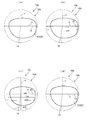
2.5 評価
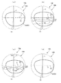
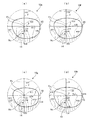
図15(a)〜(d)に、実施例1−1、実施例1−2、比較例1および従来例1のレンズ10a〜10dの外面19Aの面非点収差分布をそれぞれ示し、また、図16(a)〜(d)に実施例1−1、実施例1−2、比較例1および従来例1のレンズ10a〜10dの外面19Aの等価球面面屈折力分布を示す。等価球面面屈折力ESPは以下の式で得られる。
ESP=(OHP+OVP)/2・・・(5)
ここで、OHPは物体側の面(外面)19A上の任意の点における水平方向の面屈折力、OVPは物体側の面(外面)19Aにおける垂直方向の面屈折力である。
2.5 Evaluation FIGS. 15A to 15D show surface astigmatism distributions on the
ESP = (OHP + OVP) / 2 (5)
Here, OHP is the horizontal surface power at an arbitrary point on the object-side surface (outer surface) 19A, and OVP is the vertical surface power at the object-side surface (outer surface) 19A.
なお、それぞれの図に示した値の単位はディオプトリ(D)であり、図の縦横の直線は円形のレンズの幾何学中心を通る基準線(垂直基準線Yおよび水平基準線X)を示し、その交点である幾何学中心をフィッティングポイントPeとした眼鏡フレームへの枠入れ時の形状イメージも太い実線で示されている。また、破線で主注視線14を示している。以下に示す図においても同様である。
The unit of the values shown in each figure is diopter (D), and the vertical and horizontal straight lines in the figure indicate reference lines (vertical reference line Y and horizontal reference line X) passing through the geometric center of the circular lens, The shape image at the time of putting the frame into the spectacle frame with the geometrical center that is the intersection as the fitting point Pe is also shown by a thick solid line. Further, the
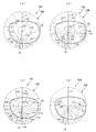
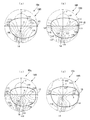
図17(a)〜(d)に実施例1−1、実施例1−2、比較例1および従来例1のレンズ10a〜10dの内面19Bの面非点収差分布を示し、図18(a)〜(d)に実施例1−1、実施例1−2、比較例1および従来例1のレンズ10a〜10dの内面19Bの等価球面面屈折力分布を示す。
FIGS. 17A to 17D show surface astigmatism distributions on the
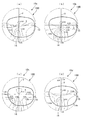
図19(a)〜(d)に実施例1−1、実施例1−2、比較例1および従来例1のレンズ10a〜10dのレンズ上の各位置を透して観察したときの非点収差分布を示し、図20(a)〜(d)に実施例1−1、実施例1−2、比較例1および従来例1のレンズ10a〜10dのレンズ上の各位置を透して観察したときの等価球面度数分布を示す。なお、図20(a)〜(d)には、遠用部測定基準点Fcおよび近用部測定基準点Ncを参考のため示してある。
FIGS. 19A to 19D show astigmatism when the positions on the
図15(a)〜(c)に示すように実施例1−1、実施例1−2および比較例1の外面19Aはトーリック面の要素を含み、それによる非点収差が発生する。図17(a)〜(c)に示すように、実施例1−1、実施例1−2および比較例1の内面19Bはトーリック面の要素を含み、図17(d)に示した従来例1の内面19Bの収差にトーリック面の要素による収差を合成した収差が発生する。ただし、非球面補正を行っているために単純な合成にはなっていない。図19(a)〜(c)に示すように、実施例1−1、実施例1−2および比較例1の外面19Aおよび内面19Bによるレンズ全体の非点収差は、図19(d)に示す非点収差とほぼ等しい。したがって、これらの実施例および比較例において、外面19Aのトーリック面の要素による面屈折力のシフトは、内面19Bにトーリック面の要素を入れることによりキャンセルできることがわかる。
Figure 15 (a) ~ embodiment, as shown in (c) 1-1, the
等価球面度数分布においても同様であり、図20(a)〜(c)に示すように、これらの実施例および比較例のレンズ10a〜10cにおいて、外面19Aにトーリック面の要素を入れ、そのトーリック面の要素による面屈折力のシフトをキャンセルするトーリック面の要素を内面19Bに導入することにより、図20(d)に示す従来例1のレンズ10dとほぼ同様の屈折力分布を得ることができる。
The same applies to the equivalent spherical power distribution. As shown in FIGS. 20A to 20C, in the
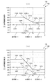
図21および図22に、実施例1−1、実施例1−2、比較例1および従来例1のレンズ10a〜10dを通して見える像のゆれを、上記において説明したゆれの評価方法により求めた結果を示している。図21は、振動に関する指標IDdを示し、図22は変形量に関する指標IDsを示す。矩形模様50の視野角ピッチは10度、頭部の振りは左右方向とし、その振り角は左右に各10度としている。
FIG. 21 and FIG. 22 show the results of obtaining the shake of the image seen through the
図21は、すべての格子線の振動の総和または平均を示す「全L」を指標IDdとし、各レンズ10a〜10dの主注視線14に沿った幾つかの視野角で求めている。それぞれのレンズ10a〜10dのフィッティングポイントPeは視野角0度の水平正面視、即ち第一眼位における装用者の視線2と外面19Aとの交点である。遠用部11はフィッティングポイントPeから上方に20度まで、中間部13はフィッティングポイントPeから下方に−28度付近までであり、そこから下が近用部12に当たる。
In FIG. 21, “all L” indicating the total or average of vibrations of all grid lines is used as an index IDd, and obtained at several viewing angles along the main line of
図22は、すべての格子線の変動面積の総和または平均を示す「全L」を指標IDsとして、各レンズ10a〜10dの主注視線14に沿った幾つかの視野角で求めている。指標IDsは変形量を比率(%)で表している。
In FIG. 22, “all L” indicating the total or average of the fluctuation areas of all grid lines is used as an index IDs, and is obtained at several viewing angles along the
図21および図22に示すように、実施例1−1および1−2のレンズ10aおよび10bにおいては、主注視線14上の遠中近のほぼすべての領域にわたって指標IDdおよび指標IDsが、従来例1のレンズ10dより小さい。したがって、実施例1−1および1−2のレンズ10aおよび10bを通して見ることにより、像のゆれを改善できることがわかった。特に遠用部11の下方から、中間部13および近用部12においてゆれの改善効果が大きいと予想される。
As shown in FIGS. 21 and 22, in the
比較例1のレンズ10cについては、遠用部11において指標IDdおよび指標IDsの改善がみられる。しかしながら、中間部13から近用部12にかけては、指標IDdおよびIDsが、ともに従来例1よりも大きくなっている。したがって、比較例1のレンズ10cでは、像のゆれの改善が得られにくいことがわかった。
For the
すなわち、外面累進タイプのレンズにおいては、内外面に垂直方向の面屈折力が水平方向の面屈折力よりも大きいトーリック面を導入しても、像のゆれを改善する効果は得られにくい。他のタイプのレンズにおいては、内外面に垂直方向の面屈折力が水平方向の面屈折力よりも大きいトーリック面を導入することにより、像のゆれを改善できることがわかった。外面累進タイプのレンズにおいては、近用部において像が拡大される傾向がある。このため、近用部にトーリック面を導入すると像の拡大傾向が増長され、像のゆれの改善効果を上回り、結果として、外面累進タイプのレンズにおいては中間部から近用部にかけて像のゆれが拡大する可能性がある。 That is, in an outer surface progressive type lens, even if a toric surface having a surface refractive power in the vertical direction larger than a surface power in the horizontal direction is introduced to the inner and outer surfaces, it is difficult to obtain the effect of improving the image shake. In other types of lenses, it has been found that image distortion can be improved by introducing a toric surface whose surface refractive power in the vertical direction is larger than that in the horizontal direction on the inner and outer surfaces. In the progressive surface type lens, the image tends to be enlarged in the near portion. For this reason, when a toric surface is introduced in the near portion, the tendency to enlarge the image is increased, which exceeds the effect of improving the image shake.As a result, in the progressive surface type lens, the image is shaken from the intermediate portion to the near portion. There is a possibility of expansion.
垂直方向の面屈折力が水平方向の面屈折力よりも大きいトーリック面の要素により像のゆれが軽減できる要因の1つは、トーリック面を導入することによりレンズを通して物体を見る際の視線の動きに対して、視線と物体側の面とのなす角度の変位を抑制できることであると考えられる。視線と物体側の面とのなす角度の変位が小さくなれば、像面湾曲などの諸収差の発生が抑制され、レンズを通して得る像のゆれの低減に効果があると考えられる。 One of the factors that can reduce the image shake by the toric surface element whose vertical surface power is larger than the horizontal surface power is the movement of the line of sight when the object is viewed through the lens by introducing the toric surface. On the other hand, it is considered that the displacement of the angle formed by the line of sight and the object side surface can be suppressed. If the displacement of the angle formed by the line of sight and the object-side surface is reduced, the occurrence of various aberrations such as field curvature is suppressed, and it is considered effective in reducing the fluctuation of the image obtained through the lens.
3. 実施形態2
3.1 実施例2−1
図23(a)および図23(b)に外面19Aおよび内面19Bの面屈折力をそれぞれ示すように、実施例2−1のレンズ10eを設計した。実施例2−1のレンズ10eは、内面19Bに累進要素を含む、内面累進レンズと称されるものである。基本的な眼鏡仕様は、屈折率1.67のレンズ基材を用い、累進帯長14mm、処方度数(遠用度数、Sph)が4.00D、加入度数(Add)が2.00Dである。なお、実施例2−1のレンズ10eの直径は65mmであり、乱視度数は含まれていない。実施例2−1のレンズ10eは、遠用部11の処方平均度数が4.0(D)の遠視用のプラス度数のレンズである。実施例2−1のレンズ10eは、内外面にトーリック面の要素を含む。図23(a)および図23(b)の表記は図11(a)および図11(b)と共通である。
3.
3.1 Example 2-1
The
実施例2−1のレンズ10eは、上記式(1a)、(1b)、(1c´)、(2a)および(2b)の条件を満たす。したがって、レンズ10eの外面19Aは第1のトーリック面の要素TF1を含み、内面19Bは第2のトーリック面の要素TF2を含む。
The
実施例2−1のレンズ10eの構成は実施例1−1のレンズ10aに類似している。具体的には、遠用部測定基準点Fcにおける垂直方向(縦方向)の面屈折力OVPf1と近用部測定基準点Ncの垂直方向の面屈折力OVPn1とが等しく、9.0(D)であり、式(1b)を満たす。また、遠用部測定基準点Fcにおける水平方向(横方向)の面屈折力OHPf1は6.0(D)で、OVPf1よりも3.0(D)小さく、式(1a)を満たす。近用部測定基準点Ncにおいては、水平方向の面屈折力OHPn1は垂直方向の面屈折力OVPn1よりも3.0(D)小さく、式(1c´)を満たす。内面19Bの遠用部測定基準点Fcに対応する点および近用部測定基準点Ncに対応する点においては、IVPf1とIHPf1との差は3.0(D)、IVPn1とIHPn1との差は3.0(D)であり、式(2a)および(2b)を満たす。すなわち、外面19Aは第1のトーリック面の要素TF1を含み、内面19Bは、外面19Aの第1のトーリック面の要素TF1をキャンセルする第2のトーリック面の要素TF2を含む。
The configuration of the
実施例2−1の外面19Aは、主注視線14に沿った垂直方向の面屈折力は、遠用部11の面屈折力OVPf、中間部13の面屈折力OVPmおよび近用部12の面屈折力OVPnは一定で、9.0(D)であり式(1ba)を満たす。水平方向の面屈折力は、遠用部11のOHPf、中間部13の面屈折力OHPmおよび近用部12の面屈折力OHPnは一定で6.0(D)である。したがって、外面19Aには、主注視線14に沿って、垂直方向の面屈折力OVPf、OVPmおよびOVPnが水平方向の面屈折力OHPf、OHPmおよびOHPnに対してそれぞれ3.0(D)大きい単純なトーリック面が形成されており、式(1aa)および(1ca´)を満たす。典型的には外面19Aの全体が単純なトーリック面である。
In the
内面19Bでは、主注視線14に対応する線に沿った垂直方向の面屈折力は、遠用部11の面屈折力IVPfは5.0(D)、中間部13の面屈折力IVPmは累進的に減少し、近用部12の面屈折力IVPnは3.0(D)であり、所定の加入度(2.0(D))を得ている。水平方向の面屈折力は、遠用部11の面屈折力IHPfは2.0(D)、中間部13の面屈折力IHPmは累進的に減少し、近用部12の面屈折力IHPnは0.0(D)であり、所定の加入度(2.0(D))を得ている。したがって、内面19Bは式(2aa)および(2ba)を満たし、外面19Aのトーリック面による面屈折力をキャンセルするトーリック面を含む。
In the
3.2 実施例2−2
図24(a)および図24(b)に外面19Aおよび内面19Bの面屈折力をそれぞれ示すように、実施例2−2のレンズ10fを設計した。実施例2−2のレンズ10fは、実施例1−2と同様に、内面19Bに累進要素を含み、外面19Aに逆累進要素を含む、外面逆累進レンズと称されるレンズである。基本的な眼鏡仕様は実施例2−1と同じである。また、図24(a)および図24(b)の表記は図11(a)および図11(b)と共通である。
3.2 Example 2-2
The
実施例2−2のレンズ10fも、上記式(1a)、(1b)、(1c´)、(2a)および(2b)の条件を満たす。したがって、レンズ10fの外面19Aは第1のトーリック面の要素TF1を含み、内面19Bは第2のトーリック面の要素TF2を含む。
The
具体的には、遠用部測定基準点Fcにおける垂直方向の面屈折力OVPf1は9.0(D)で、近用部測定基準点Ncの垂直方向の面屈折力OVPn1よりも2.0(D)大きく、式(1b)を満たす。また、遠用部測定基準点Fcにおける水平方向の面屈折力OHPf1は6.0(D)で、OVPf1よりも3.0(D)小さく、式(1a)を満たす。近用部測定基準点Ncにおいては、OHPn1はOVPn1よりも1.0(D)小さく、式(1c´)を満たす。内面19Bの遠用部測定基準点Fcおよび近用部測定基準点Ncに対応する点においては、IVPf1とIHPf1との差は3.0(D)、IVPn1とIHPn1との差は1.0(D)であり、式(2a)および(2b)を満たす。したがって、外面19Aは第1のトーリック面の要素TF1を含み、内面19Bは、外面19Aの第1のトーリック面の要素TF1をキャンセルする第2のトーリック面の要素TF2を含む。
Specifically, the surface refractive power OVPf 1 in the vertical direction at the distance measurement reference point Fc is 9.0 (D), which is 2. (D) higher than the surface power OVPn 1 in the vertical direction at the near measurement reference point Nc. 0 (D) large and satisfies the formula (1b). Further, the horizontal surface power OHPf 1 at the distance measurement reference point Fc is 6.0 (D), which is 3.0 (D) smaller than OVPf 1 and satisfies the formula (1a). At the near portion measurement reference point Nc, OHPn 1 is 1.0 (D) smaller than OVPn 1 and satisfies the equation (1c ′). At the points corresponding to the distance measurement reference point Fc and the near measurement reference point Nc on the
実施例2−2のレンズ10fの主注視線14に沿った面においては、外面19Aの垂直方向の面屈折力は、遠用部11の面屈折力OVPfは9.0(D)、中間部13の面屈折力IVPmは累進的に減少し、近用部12の面屈折力IVPnは7.0(D)である。外面19Aの水平方向の面屈折力は、遠用部11の面屈折力OHPf、中間部13の面屈折力OHPmおよび近用部12の面屈折力OHPnは一定で6.0(D)である。したがって、外面19Aには、主注視線14に沿って、遠用部11では垂直方向の面屈折力OVPfが水平方向の面屈折力OHPfに対し3.0(D)大きく、近用部12では垂直方向の面屈折力OVPnが水平方向の面屈折力OHPnに対して1.0(D)大きいトーリック面が形成されている。したがって、式(1aa)、(1ba)および(1ca´)を満たす。
On the surface along the main line of
内面19Bの垂直方向の面屈折力は、遠用部11の面屈折力IVPfは5.0(D)、中間部13の面屈折力IVPmは累進的に減少し、近用部12の面屈折力IVPnは1.0(D)であり、外面19Aの垂直方向の面屈折力に対し所定の加入度(2.0(D))を得ている。水平方向の面屈折力は、遠用部11の面屈折力IHPfは2.0(D)、中間部13の面屈折力IHPmは累進的に減少し、近用部12の面屈折力IHPnは0.0(D)であり、外面19Aの水平方向の面屈折力に対し所定の加入度(2.0(D))を得ている。したがって、式(2aa)および(2ba)を満たし、内面19Bは外面19Aのトーリック面による面屈折力をキャンセルするトーリック面を含む。
The surface refractive power in the vertical direction of the
3.3 比較例2
図25(a)および図25(b)に外面19Aおよび内面19Bの面屈折力をそれぞれ示すように、比較例2のレンズ10gを設計した。比較例2のレンズ10gは、外面19Aおよび内面19Bに累進要素を含む、内外面累進レンズまたは外面累進レンズと称されるレンズである。基本的な眼鏡仕様は実施例2−1と同じである。また、図25(a)および図25(b)の表記は図11(a)および図11(b)と共通である。
3.3 Comparative Example 2
The
比較例2のレンズ10gは、遠用部測定基準点Fcにおける垂直方向の面屈折力OVPf1よりも近用部測定基準点Ncにおける垂直方向の面屈折力OVPn1が大きい。したがって、比較例1と同様に、式(1a)、(1c´)、(2a)および(2b)の条件を満たすが、式(1b)を満たさない。したがって、レンズ10gは内外面でキャンセルするトーリック面を含むが、第1のトーリック面の要素TF1および第2のトーリック面の要素TF2は含まない。
具体的には、遠用部測定基準点Fcにおける水平方向の面屈折力OHPf1は6.0(D)で、OVPf1よりも3.0(D)小さく、式(1a)を満たす。しかしながら、遠用部測定基準点Fcにおける垂直方向の面屈折力OVPf1は9.0(D)で、近用部測定基準点Ncの垂直方向の面屈折力OVPn1よりも2.0(D)小さく、式(1b)を満たさない。近用部測定基準点Ncにおいては、OHPn1はOVPn1よりも5.0(D)小さく、式(1c´)を満たす。内面19Bにおいては、遠用部測定基準点Fcおよび近用部測定基準点Ncに対応する点において、IVPf1とIHPf1との差は3.0(D)、IVPn1とIHPn1との差は5.0(D)であり、式(2a)および(2b)を満たす。したがって、外面19Aは第1のトーリック面の要素TF1を含まないが、外面19Aおよび内面19Bは相互にキャンセルするトーリック面の要素を含む。
Specifically, the horizontal surface power OHPf 1 at the distance measurement reference point Fc is 6.0 (D), which is 3.0 (D) smaller than OVPf 1 and satisfies the formula (1a). However, the vertical surface power OVPf 1 at the distance measurement reference point Fc is 9.0 (D), which is 2.0 (D) than the vertical surface power OVPn 1 at the near distance measurement reference point Nc. ) Small and does not satisfy the formula (1b). At the near portion measurement reference point Nc, OHPn 1 is 5.0 (D) smaller than OVPn 1 and satisfies the equation (1c ′). Difference in the
比較例1のレンズ10gの主注視線14に沿った面屈折力では、外面19Aの垂直方向の面屈折力は、遠用部11の面屈折力OVPfは9.0(D)、中間部13の面屈折力OVPmは累進的に増大し、近用部12の面屈折力OVPnは11.0(D)である。外面19Aの水平方向の面屈折力は、遠用部11の面屈折力OHPf、中間部13の面屈折力OHPmおよび近用部12の面屈折力OHPnが一定で6.0(D)である。したがって、外面19Aには、主注視線14に沿って、遠用部11では垂直方向の面屈折力OVPfが水平方向の面屈折力OHPfに対し3.0(D)大きく、近用部12では垂直方向の面屈折力OVPnが水平方向の面屈折力OHPnに対して5.0(D)大きいトーリック面が形成されている。したがって、式(1aa)および(1ca´)は満たすが、式(1ba)は満たさない。
In the surface refractive power along the main line of
内面19Bの垂直方向の面屈折力は、遠用部11の面屈折力IVPf、中間部13の面屈折力IVPmおよび近用部12の面屈折力IVPnが5.0(D)と一定であり、外面19Aの垂直方向の面屈折力に対し所定の加入度(2.0(D))を得ている。水平方向の面屈折力は、遠用部11の面屈折力IHPfは2.0(D)、中間部13の面屈折力IHPmは累進的に減少し、近用部12の面屈折力IHPnは0.0(D)であり、外面19Aの水平方向の面屈折力に対し所定の加入度(2.0(D))を得ている。
The surface refractive power in the vertical direction of the
レンズ10gの内面19Bおいては、主注視線14に対応する線に沿って、遠用部11では垂直方向の面屈折力IVPfが水平方向の面屈折力IHPfに対し3.0(D)大きく、近用部12では垂直方向の面屈折力IVPnが水平方向の面屈折力IHPnに対して5.0(D)大きい。したがって、式(2aa)および(2ba)を満足し、内面19Bに形成されたトーリック面は、外面19Aのトーリック面による面屈折力をキャンセルしている。
In the
3.4 従来例2
図26(a)および図26(b)に外面19Aおよび内面19Bの面屈折力をそれぞれ示すように、従来例2のレンズ10hを設計した。従来例2のレンズ10hは、外面19Aが球面で内面19Bに累進要素を含む、内面累進レンズと称されるレンズである。基本的な眼鏡仕様は実施例2−1と同じである。また、図26(a)および図26(b)の表記は図11(a)および図11(b)と共通である。
3.4 Conventional Example 2
The
従来例2のレンズ10hは、外面19Aの垂直方向の面屈折力OVPf、OVPmおよびOVPnが水平方向の面屈折力OHPf、OHPmおよびOHPnに等しく6.0(D)である。内面19Bの垂直方向の面屈折力IVPf、IVPmおよびIVPnは、水平方向の面屈折力IHPf、IHPmおよびIHPnにそれぞれ等しく、遠用部11の面屈折力は2.0(D)、近用部12の面屈折力は0.0(D)となり所定の加入度を得ている。したがって、この従来例2のレンズ10hの外面19Aおよび内面19Bはトーリック面を含まない。
In the
3.5 評価
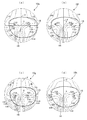
図27(a)〜(d)に、実施例2−1、実施例2−2、比較例2および従来例2のレンズ10e〜10hの外面19Aの面非点収差分布をそれぞれ示し、また、図28(a)〜(d)に実施例2−1、実施例2−2、比較例2および従来例2のレンズ10e〜10hの外面19Aの等価球面面屈折力分布を示す。
3.5 Evaluation FIGS. 27A to 27D show surface astigmatism distributions on the
図29(a)〜(d)に実施例2−1、実施例2−2、比較例2および従来例2のレンズ10e〜10hの内面19Bの面非点収差分布を示し、図30(a)〜(d)に実施例2−1、実施例2−2、比較例2および従来例2のレンズ10e〜10hの内面19Bの等価球面面屈折力分布を示す。
FIGS. 29A to 29D show surface astigmatism distributions on the
図31(a)〜(d)に実施例2−1、実施例2−2、比較例2および従来例2のレンズ10e〜10hのレンズ上の各位置を透して観察したときの非点収差分布を示し、図32(a)〜(d)に実施例2−1、実施例2−2、比較例2および従来例2のレンズ10e〜10hのレンズ上の各位置を透して観察したときの等価球面度数分布を示す。
FIGS. 31A to 31D show astigmatism when observed through each position on the
これらの実施例、比較例および従来例においても、図27(a)〜(c)に示す外面19Aのトーリック面の要素による非点収差が、図29(a)〜(c)に示す内面19Bのトーリック面の要素によりキャンセルされ、図31(a)〜(d)に示すように、レンズ全体としては、従来例2のレンズ10hと同様の非点収差を備えた実施例2−1、実施例2−2および比較例2のレンズ10e〜10gが得られる。等価球面度数分布においても同様である。
These examples, in Comparative Examples and Conventional Example, astigmatism by the elements of a toric surface of the
図33および図34に、実施例2−1、実施例2−2、比較例2および従来例2のレンズ10e〜10hを通して見える像のゆれを、図21および図22と同様に評価した結果を示している。実施例2−1および2−2のレンズ10eおよび10fにおいては、主注視線14上の遠中近のほぼすべての領域にわたって指標IDdおよび指標IDsが従来例1のレンズ10hと同じか小さい。したがって、実施例2−1および2−2のレンズ10eおよび10fを通して見ることにより、像のゆれを改善できることがわかった。特に遠用部11および近用部12においてゆれの改善効果が大きいと予想される。
FIG. 33 and FIG. 34 show the results of evaluating the image shake seen through the
比較例2のレンズ10gについては、遠用部11において指標IDdおよび指標IDsの改善がみられる。しかしながら、中間部13から近用部12の一部にかけては、指標IDdおよびIDsが従来例2よりも大きくなる。したがって、比較例2のレンズ10gにおいても、像のゆれの改善が得られにくいことがわかった。
In the
このように、レンズ10の外面19Aおよび内面19Bにトーリック面の要素を導入することにより、処方度数(遠用度数)が0.0(D)のプラノレンズ、および処方度数がプラスの遠視用のレンズにおいて像のゆれが改善できることがわかった。同様に、処方度数がマイナスの近視用のレンズにおいても像のゆれを改善できる。
As described above, by introducing the toric surface element to the
さらに、内外面にトーリック面の要素を持つレンズ10は、垂直方向の面屈折力が水平方向の面屈折力よりも大きい。逆に言うと、水平方向の面屈折力が垂直方向の面屈折力よりも小さく、水平方向の曲率が小さくなる。このため、水平方向に長く、顔に沿ってカーブする眼鏡レンズに適している。また、枠入れの際に、レンズ10の水平方向(横方向、左右方向)に長い楕円形(横長)のレンズを形成しやすい。したがって、垂直方向の面屈折力が水平方向の面屈折力よりも大きいトーリック面の要素を持つレンズ10は、大きな眼鏡フレーム20に対して適応しやすいレンズを提供できるという利点も備えている。
Further, the
なお、上記においては、評価のための観察指標の模様として正方格子の矩形模様50を用いたが、水平方向と垂直方向での格子のピッチを変えることにより各方向での評価の精度や密度を変えたり、さらに格子の本数を増やすことにより、評価の精度・密度を変えることも可能である。
In the above description, the
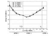
図35に、光線追跡法により求めた、比較例2のレンズ10gおよび従来例2のレンズ10hの主注視線14上の像倍率を示している。比較例2のレンズ10gの像倍率は、主注視線14上の遠用部11の下側から近用部12に至る広い範囲において、従来例2のレンズ10hの像倍率よりも大きくなっている。特に、中間部13の全域から近用部12の上側において、像倍率が大きく向上している。したがって、中間部13から近用部12にかけての広い領域において、視野が良好になると考えられる。図示していないが、比較例1の像倍率と従来例1の像倍率とを比較した場合も同様の結果が得られる。
FIG. 35 shows image magnifications on the main line of
比較例1および比較例2のレンズ10は、遠用部測定基準点Fcおよび近用部測定基準点Ncにおいて以下の条件を満たす。
OVPf1>OHPf1・・・(1a)
OVPn1>OVPf1・・・(1d)
OVPn1≧OHPn1・・・(1c)
OVPn1>OHPn1・・・(1c´)
IVPf1−IHPf1=OVPf1−OHPf1・・・(2a)
IVPn1−IHPn1=OVPn1−OHPn1・・・(2b)
このような垂直方向のトーリック面を内外に備えたレンズは、像のゆれの改善に対し像倍率を向上する効果がいっそう得られやすいレンズであることがわかった。
The
OVPf 1 > OHPf 1 (1a)
OVPn 1 > OVPf 1 (1d)
OVPn 1 ≧ OHPn 1 (1c)
OVPn 1 > OHPn 1 (1c ′)
IVPf 1 -IHPf 1 = OVPf 1 -OHPf 1 (2a)
IVPn 1 -IHPn 1 = OVPn 1 -OHPn 1 (2b)
It has been found that a lens having such a toric surface in the vertical direction on the inside and outside is a lens in which the effect of increasing the image magnification can be more easily obtained with respect to the improvement of image fluctuation.
なお、比較例1および比較例2の主注視線14に沿った面は以下の条件を満たす。
OVPf>OHPf・・・(1aa)
OVPn>OVPf・・・(1da)
OVPn≧OHPn・・・(1ca)
OVPn>OHPn・・・(1ca´)
IVPf−IHPf=OVPf−OHPf・・・(2aa)
IVPn−IHPn=OVPn−OHPn・・・(2ba)
In addition, the surface along the
OVPf> OHPf (1aa)
OVPn> OVPf (1da)
OVPn ≧ OHPn (1ca)
OVPn> OHPn (1ca ′)
IVPf−IHPf = OVPf−OHPf (2aa)
IVPn-IHPn = OVPn-OHPn (2ba)
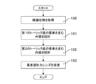
図36に、上述した眼鏡用の累進屈折力レンズを設計および製造する過程の概要を示している。ステップ100においてユーザーの眼鏡仕様を取得すると、ステップ101において、条件(1a)〜(1c)を満たす第1のトーリック面の要素TF1を含む外面(物体側の面)19Aを設計する。第1のトーリック面の要素TF1は、条件(1c´)を含むことが望ましい。
FIG. 36 shows an outline of the process of designing and manufacturing the above-described progressive-power lens for spectacles. When the spectacle specification of the user is acquired in
次に、ステップ102において、条件(2a)および(2b)を含む、第2のトーリック面の要素TF2を含む内面(眼球側の面)19Bを設計する。第2のトーリック面の要素TF2は、トーリック面であって、第1のトーリック面の要素TF1により外面19Aに形成される面屈折力のシフトをキャンセルするものである。さらに、ステップ103において、上記のステップで設計されたレンズ10を製造する。
Next, in
この設計方法は、CPUおよびメモリなどの適当なハードウェア資源を含むコンピュータが上記処理100〜102を実行するコンピュータプログラム(プログラム製品)としてメモリやROMなどの適当な媒体に記録して提供できる。ネットワークを通じて提供してもよい。
This design method can be provided by being recorded in a suitable medium such as a memory or ROM as a computer program (program product) for a computer including appropriate hardware resources such as a CPU and a memory to execute the
図37に、レンズ10の設計装置の一例を示している。この設計装置200は、眼鏡仕様に基づきレンズ10を設計する設計ユニット210と、設計されたレンズ10のゆれ指標IDdおよびIDsを上記の方法により求めて評価する評価ユニット220と、評価ユニット220で求められたゆれ指標IDdをユーザー(装着者)が見やすい状態、たとえば、グラフ化して出力する出力ユニット230とを含む。出力ユニット230により、ユーザーはゆれの少ないレンズ10を自らの判断で選択することが可能となる。
FIG. 37 shows an example of a design apparatus for the
設計ユニット210は、物体側の面(外面)19Aを設計する第1のユニット211と、眼球側の面(内面)19Bを設計する第2のユニット212とを含む。第1のユニット211は上述した設計方法のステップ101の処理を行う機能を有し、第2のユニット212は上述した設計方法のステップ102の処理を行う機能を有する。設計装置200の一例は、CPU、メモリおよびディスプレイといった資源を備えたパーソナルコンピュータであり、パーソナルコンピュータを設計装置200として機能させるプログラムをダウンロードして実行することにより上記の機能を含む設計装置200を実現できる。
The
以上の説明は遠用処方に乱視処方がない場合についてのものであったが、乱視処方がある場合には、内面側に乱視補正のためのトーリック面(トロイダル面)成分を合成することにより乱視処方を含めることが可能である。また、レンズの肉厚が大きい場合にはシェープファクターを考慮して、内面側に補正を加えることにより、より精度良いレンズを提供することが出来る。 The above explanation is for the case where there is no astigmatism prescription in the distance prescription. A prescription can be included. Further, when the lens thickness is large, a lens with higher accuracy can be provided by correcting the inner surface side in consideration of the shape factor.
1 眼鏡、 10、10L、10R レンズ
11 遠用部、 12 近用部、 13 中間部(累進部)
19A 物体側の面、 19B 眼球側の面
20 フレーム
1 Glasses, 10, 10L,
19A Object side surface, 19B
Claims (5)
第1のトーリック面の要素を含む物体側の面と、
前記第1のトーリック面の要素をキャンセルする第2のトーリック面の要素を含む眼球側の面と、
を有し、
前記第1のトーリック面の要素は、前記物体側の面の前記遠用部に予め定められる遠用部測定基準点における垂直方向の面屈折力OVPf1が、前記遠用部測定基準点における水平方向の面屈折力OHPf1よりも大きく、かつ、前記OVPf1が、前記物体側の面の前記近用部に予め定められる近用部測定基準点における垂直方向の面屈折力OVPn1 よりも大きい、
累進屈折力レンズ。 A progressive-power lens including a distance portion and a near portion,
An object side surface including elements of a first toric surface;
An eyeball-side surface including a second toric surface element that cancels the first toric surface element;
Have
The element of the first toric surface has a surface refractive power OVPf 1 in a vertical direction at a distance measurement reference point predetermined for the distance portion of the object side surface, and a horizontal surface power at the distance measurement reference point. The surface refractive power OHPf 1 in the direction is larger, and the OVPf 1 is larger than the surface refractive power OVPn 1 in the vertical direction at the near portion measurement reference point predetermined for the near portion on the object side surface. ,
Progressive power lens.
前記第1のトーリック面の要素は、前記OVPn1が、前記近用部測定基準点における水平方向の面屈折力OHPn1よりも大きい、累進屈折力レンズ。 In claim 1,
The elements of the first toric surface, the OVPn 1 is greater than the horizontal surface power OHPn 1 in the near reference point, the progressive addition lens.
前記第2のトーリック面の要素の、前記眼球側の面の前記遠用部測定基準点に対応する点における垂直方向の面屈折力IVPf1、前記遠用部測定基準点に対応する点における水平方向の面屈折力IHPf1、前記眼球側の面の前記近用部測定基準点に対応する点における垂直方向の面屈折力IVPn1、前記近用部測定基準点に対応する点における水平方向の面屈折力IHPn1、前記OVPf1、前記OHPf1、前記OVPn1、および前記OHPn1が、以下の条件を満たす、累進屈折力レンズ。
IVPf1−IHPf1=OVPf1−OHPf1
IVPn1−IHPn1=OVPn1−OHPn1
ただし、乱視処方を含まず、前記IVPf1、IHPf1、IVPn1およびIHPn1は絶対値である。 In claim 2,
The surface refractive power IVPf 1 in the vertical direction at the point corresponding to the distance measurement reference point on the eyeball side surface of the element of the second toric surface, and the horizontal at the point corresponding to the distance measurement reference point Surface refractive power IHPf 1 in the direction, vertical surface power IVPn 1 at a point corresponding to the near portion measurement reference point on the eyeball side surface, and horizontal direction power at a point corresponding to the near portion measurement reference point A progressive-power lens in which the surface refractive power IHPn 1 , the OVPf 1 , the OHPf 1 , the OVPn 1 , and the OHPn 1 satisfy the following conditions.
IVPf 1 −IHPf 1 = OVPf 1 −OHPf 1
IVPn 1 -IHPn 1 = OVPn 1 -OHPn 1
However, astigmatism prescription is not included, and the IVPf 1 , IHPf 1 , IVPn 1 and IHPn 1 are absolute values.
第1のトーリック面の要素を含むように物体側の面を設計することと、
前記第1のトーリック面の要素をキャンセルする第2のトーリック面の要素を含むように、眼球側の面を設計することと、
を含み、
前記第1のトーリック面の要素は、前記物体側の面の前記遠用部に予め定められる遠用部測定基準点における垂直方向の面屈折力OVPf1が、前記遠用部測定基準点における水平方向の面屈折力OHPf1よりも大きく、かつ、前記OVPf1が、前記物体側の面の前記近用部に予め定められる近用部測定基準点における垂直方向の面屈折力OVPn1 よりも大きい、
累進屈折力レンズの設計方法。 In a design method of a progressive power lens including a distance portion and a near portion,
Designing the object-side surface to include elements of the first toric surface;
Designing an eyeball-side surface to include a second toric surface element that cancels the first toric surface element;
Including
The element of the first toric surface has a surface refractive power OVPf 1 in a vertical direction at a distance measurement reference point predetermined for the distance portion of the object side surface, and a horizontal surface power at the distance measurement reference point. The surface refractive power OHPf 1 in the direction is larger, and the OVPf 1 is larger than the surface refractive power OVPn 1 in the vertical direction at the near portion measurement reference point predetermined for the near portion on the object side surface. ,
Design method for progressive power lens.
Priority Applications (5)
| Application Number | Priority Date | Filing Date | Title |
|---|---|---|---|
| JP2012086221A JP5976366B2 (en) | 2012-04-05 | 2012-04-05 | Progressive power lens and progressive power lens design method |
| PCT/JP2013/060516 WO2013151165A1 (en) | 2012-04-05 | 2013-04-05 | Progressive-power lens and method for designing progressive-power lens |
| US14/390,942 US20150055083A1 (en) | 2012-04-05 | 2013-04-05 | Progressive addition lens and method for designing progressive addition lens |
| EP13773153.5A EP2835682A4 (en) | 2012-04-05 | 2013-04-05 | Progressive-power lens and method for designing progressive-power lens |
| CN201380018599.5A CN104220923B (en) | 2012-04-05 | 2013-04-05 | The method for designing of progressive refractive power glasses lens and progressive refractive power glasses lens |
Applications Claiming Priority (1)
| Application Number | Priority Date | Filing Date | Title |
|---|---|---|---|
| JP2012086221A JP5976366B2 (en) | 2012-04-05 | 2012-04-05 | Progressive power lens and progressive power lens design method |
Publications (3)
| Publication Number | Publication Date |
|---|---|
| JP2013218004A JP2013218004A (en) | 2013-10-24 |
| JP2013218004A5 JP2013218004A5 (en) | 2015-04-09 |
| JP5976366B2 true JP5976366B2 (en) | 2016-08-23 |
Family
ID=49300641
Family Applications (1)
| Application Number | Title | Priority Date | Filing Date |
|---|---|---|---|
| JP2012086221A Active JP5976366B2 (en) | 2012-04-05 | 2012-04-05 | Progressive power lens and progressive power lens design method |
Country Status (5)
| Country | Link |
|---|---|
| US (1) | US20150055083A1 (en) |
| EP (1) | EP2835682A4 (en) |
| JP (1) | JP5976366B2 (en) |
| CN (1) | CN104220923B (en) |
| WO (1) | WO2013151165A1 (en) |
Families Citing this family (7)
| Publication number | Priority date | Publication date | Assignee | Title |
|---|---|---|---|---|
| JP6095271B2 (en) * | 2012-03-05 | 2017-03-15 | イーエイチエス レンズ フィリピン インク | Lens set, lens design method, and lens manufacturing method |
| BR112016028281B8 (en) * | 2014-06-04 | 2022-11-16 | Hoya Lens Thailand Ltd | PROGRESSIVE ADDING LENS |
| CN106461977B (en) * | 2014-06-04 | 2020-07-17 | 豪雅镜片泰国有限公司 | Progressive-power lens |
| JP6483147B2 (en) * | 2014-10-10 | 2019-03-13 | ホヤ レンズ タイランド リミテッドHOYA Lens Thailand Ltd | Progressive power lens |
| WO2017081065A1 (en) * | 2015-11-13 | 2017-05-18 | Essilor International (Compagnie Generale D'optique) | Lenses with improved management of distortion |
| JP2019139120A (en) * | 2018-02-14 | 2019-08-22 | 東海光学株式会社 | Bifocal lens and method of manufacturing bifocal lens |
| JP7175325B2 (en) * | 2018-09-28 | 2022-11-18 | ホヤ レンズ タイランド リミテッド | Progressive power lens, design method thereof, and manufacturing method thereof |
Family Cites Families (11)
| Publication number | Priority date | Publication date | Assignee | Title |
|---|---|---|---|---|
| JP2002372689A (en) * | 1995-11-24 | 2002-12-26 | Seiko Epson Corp | Progressive power lens and eyeglass lens |
| JP3852116B2 (en) * | 1995-11-24 | 2006-11-29 | セイコーエプソン株式会社 | Progressive multifocal lens and spectacle lens |
| JP3617004B2 (en) | 2002-05-28 | 2005-02-02 | Hoya株式会社 | Double-sided aspherical progressive-power lens |
| US7125118B2 (en) * | 2003-04-02 | 2006-10-24 | Seiko Epson Corporation | Progressive multifocal lens and method of designing the same |
| ATE439617T1 (en) * | 2003-11-27 | 2009-08-15 | Hoya Corp | DOUBLE-SIDED PROGRESSIVE LENS |
| JP4437482B2 (en) * | 2003-11-27 | 2010-03-24 | Hoya株式会社 | Double-sided aspherical progressive-power lens and design method thereof |
| CN100495124C (en) * | 2003-11-27 | 2009-06-03 | Hoya株式会社 | Both-sided aspherical varifocal lens and method of designing it |
| DE102009005214A1 (en) * | 2009-01-20 | 2010-07-22 | Rodenstock Gmbh | Automatic progressive lens design modification |
| JP2012013742A (en) * | 2010-06-29 | 2012-01-19 | Seiko Epson Corp | Progressive refractive power eyeglass lens and design method thereof |
| JP5822483B2 (en) * | 2011-02-23 | 2015-11-24 | イーエイチエス レンズ フィリピン インク | Eyeglass lenses |
| JP5872785B2 (en) * | 2011-04-07 | 2016-03-01 | イーエイチエス レンズ フィリピン インク | Progressive power lens design method |
-
2012
- 2012-04-05 JP JP2012086221A patent/JP5976366B2/en active Active
-
2013
- 2013-04-05 CN CN201380018599.5A patent/CN104220923B/en not_active Expired - Fee Related
- 2013-04-05 EP EP13773153.5A patent/EP2835682A4/en not_active Withdrawn
- 2013-04-05 US US14/390,942 patent/US20150055083A1/en not_active Abandoned
- 2013-04-05 WO PCT/JP2013/060516 patent/WO2013151165A1/en active Application Filing
Also Published As
| Publication number | Publication date |
|---|---|
| EP2835682A1 (en) | 2015-02-11 |
| US20150055083A1 (en) | 2015-02-26 |
| WO2013151165A1 (en) | 2013-10-10 |
| CN104220923B (en) | 2016-04-27 |
| EP2835682A4 (en) | 2015-12-02 |
| CN104220923A (en) | 2014-12-17 |
| JP2013218004A (en) | 2013-10-24 |
Similar Documents
| Publication | Publication Date | Title |
|---|---|---|
| JP5976366B2 (en) | Progressive power lens and progressive power lens design method | |
| US9010932B2 (en) | Spectacle lens | |
| JP5952541B2 (en) | Optical lens, optical lens design method, and optical lens manufacturing apparatus | |
| JP5822483B2 (en) | Eyeglass lenses | |
| JP5872785B2 (en) | Progressive power lens design method | |
| EP2492740B1 (en) | Progressive power lens and method for manufacturing of the progressive-power lens | |
| JP5822484B2 (en) | Eyeglass lenses | |
| JP5822482B2 (en) | Eyeglass lenses | |
| JP5789108B2 (en) | Progressive power lens and design method thereof | |
| JP4243335B2 (en) | Progressive power lens | |
| JP5872767B2 (en) | Eyeglass lens, performance evaluation method, design method, and manufacturing method thereof | |
| JP6095271B2 (en) | Lens set, lens design method, and lens manufacturing method | |
| JP2014106385A (en) | Progressive power lens and method of designing progressive power lens | |
| JP2004514946A (en) | Progressive eyeglass lenses for far and intermediate object distances | |
| JP7405371B2 (en) | How to design gaming lenses | |
| JP2013182250A (en) | Lens set, lens design method, and lens manufacture method | |
| JP2013182249A (en) | Lens set, lens design method, and lens manufacture method |
Legal Events
| Date | Code | Title | Description |
|---|---|---|---|
| A521 | Request for written amendment filed |
Free format text: JAPANESE INTERMEDIATE CODE: A523 Effective date: 20150220 |
|
| A621 | Written request for application examination |
Free format text: JAPANESE INTERMEDIATE CODE: A621 Effective date: 20150220 |
|
| A131 | Notification of reasons for refusal |
Free format text: JAPANESE INTERMEDIATE CODE: A131 Effective date: 20160216 |
|
| A601 | Written request for extension of time |
Free format text: JAPANESE INTERMEDIATE CODE: A601 Effective date: 20160516 |
|
| A521 | Request for written amendment filed |
Free format text: JAPANESE INTERMEDIATE CODE: A523 Effective date: 20160527 |
|
| TRDD | Decision of grant or rejection written | ||
| A01 | Written decision to grant a patent or to grant a registration (utility model) |
Free format text: JAPANESE INTERMEDIATE CODE: A01 Effective date: 20160628 |
|
| A61 | First payment of annual fees (during grant procedure) |
Free format text: JAPANESE INTERMEDIATE CODE: A61 Effective date: 20160720 |
|
| R150 | Certificate of patent or registration of utility model |
Ref document number: 5976366 Country of ref document: JP Free format text: JAPANESE INTERMEDIATE CODE: R150 |
|
| R250 | Receipt of annual fees |
Free format text: JAPANESE INTERMEDIATE CODE: R250 |
|
| R250 | Receipt of annual fees |
Free format text: JAPANESE INTERMEDIATE CODE: R250 |
|
| R250 | Receipt of annual fees |
Free format text: JAPANESE INTERMEDIATE CODE: R250 |
|
| R250 | Receipt of annual fees |
Free format text: JAPANESE INTERMEDIATE CODE: R250 |
|
| R250 | Receipt of annual fees |
Free format text: JAPANESE INTERMEDIATE CODE: R250 |