JP5970909B2 - Clamp mechanism and substrate bonding apparatus - Google Patents

Clamp mechanism and substrate bonding apparatus Download PDF

Info

Publication number
JP5970909B2
JP5970909B2 JP2012074651A JP2012074651A JP5970909B2 JP 5970909 B2 JP5970909 B2 JP 5970909B2 JP 2012074651 A JP2012074651 A JP 2012074651A JP 2012074651 A JP2012074651 A JP 2012074651A JP 5970909 B2 JP5970909 B2 JP 5970909B2
Authority
JP
Japan
Prior art keywords
substrate holder
substrate
coupling
coupled
stress
Prior art date
Legal status (The legal status is an assumption and is not a legal conclusion. Google has not performed a legal analysis and makes no representation as to the accuracy of the status listed.)
Active
Application number
JP2012074651A
Other languages
Japanese (ja)
Other versions
JP2013207094A5 (en
JP2013207094A (en
Inventor
白数 廣
廣 白数
前田 栄裕
栄裕 前田
教宏 三池
教宏 三池
伸之 笹倉
伸之 笹倉
翔太 宮崎
翔太 宮崎
Current Assignee (The listed assignees may be inaccurate. Google has not performed a legal analysis and makes no representation or warranty as to the accuracy of the list.)
Nikon Corp
Original Assignee
Nikon Corp
Priority date (The priority date is an assumption and is not a legal conclusion. Google has not performed a legal analysis and makes no representation as to the accuracy of the date listed.)
Filing date
Publication date
Application filed by Nikon Corp filed Critical Nikon Corp
Priority to JP2012074651A priority Critical patent/JP5970909B2/en
Publication of JP2013207094A publication Critical patent/JP2013207094A/en
Publication of JP2013207094A5 publication Critical patent/JP2013207094A5/ja
Application granted granted Critical
Publication of JP5970909B2 publication Critical patent/JP5970909B2/en
Active legal-status Critical Current
Anticipated expiration legal-status Critical

Links

Images

Landscapes

  • Container, Conveyance, Adherence, Positioning, Of Wafer (AREA)

Description

本発明は、クランプ機構、及び、基板貼り合わせ装置に関する。   The present invention relates to a clamp mechanism and a substrate bonding apparatus.

一対の基板ホルダを有する基板ホルダ対に積層された状態で保持された複数の基板を接合する基板貼り合わせ方法が知られている(例えば、特許文献1参照)。基板ホルダ対の一対の基板ホルダは、磁力等によって互いに結合する結合部材を有する。少なくとも一方の結合部材は、弾性部材によって基板ホルダに設けられている。結合部材が結合することにより、一対の基板ホルダの間で複数の基板が挟持される。
[特許文献1] 特開2010−10628号公報
A substrate bonding method for bonding a plurality of substrates held in a state of being stacked on a pair of substrate holders having a pair of substrate holders is known (for example, see Patent Document 1). The pair of substrate holders of the pair of substrate holders has a coupling member that couples to each other by magnetic force or the like. At least one of the coupling members is provided on the substrate holder by an elastic member. When the coupling member is coupled, the plurality of substrates are sandwiched between the pair of substrate holders.
[Patent Document 1] Japanese Patent Application Laid-Open No. 2010-10628

しかしながら、一対の基板ホルダが互いに結合すると、弾性部材が変形して、挟持された複数の基板の相対位置がずれるといった課題がある。   However, when the pair of substrate holders are coupled to each other, there is a problem that the elastic member is deformed and the relative positions of the plurality of sandwiched substrates are shifted.

本発明の第1の態様においては、第1ホルダ本体と、前記第1ホルダ本体に設けられた第1結合部材とを有する第1基板ホルダと、前記第1ホルダ本体との間で複数の基板を挟持する第2ホルダ本体と、前記第2ホルダ本体に設けられ前記第1結合部材と結合する第2結合部材と、前記第2ホルダ本体と前記第2結合部材とを連結するとともに弾性変形可能な弾性部材とを有する第2基板ホルダと、前記第1結合部材と、前記第2結合部材とが結合することにより前記弾性部材に発生する前記基板の面方向の応力を低減する応力低減部とを備えるクランプ機構を提供する。   In the first aspect of the present invention, a plurality of substrates are provided between the first holder body having a first holder body and a first coupling member provided on the first holder body, and the first holder body. A second holder main body that sandwiches the first coupling member, a second coupling member that is provided in the second holder main body and that couples to the first coupling member, and connects the second holder main body and the second coupling member and is elastically deformable. A second substrate holder having a flexible elastic member, the first coupling member, and a stress reducing unit that reduces the stress in the surface direction of the substrate generated in the elastic member by coupling the second coupling member; A clamp mechanism is provided.

本発明の第2の態様においては、上述のクランプ機構を備える基板貼り合わせ装置を提供する。   In the 2nd aspect of this invention, a board | substrate bonding apparatus provided with the above-mentioned clamp mechanism is provided.

なお、上記の発明の概要は、本発明の必要な特徴の全てを列挙したものではない。また、これらの特徴群のサブコンビネーションもまた、発明となりうる。   It should be noted that the above summary of the invention does not enumerate all the necessary features of the present invention. In addition, a sub-combination of these feature groups can also be an invention.

基板貼り合わせ装置10の全体構成図である。1 is an overall configuration diagram of a substrate bonding apparatus 10. FIG. 基板貼り合わせ装置10による貼り合わせ基板95の貼り合せ工程を説明する図である。It is a figure explaining the bonding process of the bonding board | substrate 95 by the board | substrate bonding apparatus 10. FIG. 基板貼り合わせ装置10による貼り合わせ基板95の貼り合せ工程を説明する図である。It is a figure explaining the bonding process of the bonding board | substrate 95 by the board | substrate bonding apparatus 10. FIG. 基板貼り合わせ装置10による貼り合わせ基板95の貼り合せ工程を説明する図である。It is a figure explaining the bonding process of the bonding board | substrate 95 by the board | substrate bonding apparatus 10. FIG. 基板貼り合わせ装置10による貼り合わせ基板95の貼り合せ工程を説明する図である。It is a figure explaining the bonding process of the bonding board | substrate 95 by the board | substrate bonding apparatus 10. FIG. クランプ機構の一方の基板ホルダ94である上基板ホルダ100の底面図である。It is a bottom view of the upper substrate holder 100 which is one substrate holder 94 of a clamp mechanism. 下方から見た上基板ホルダ100の斜視図である。It is a perspective view of the upper substrate holder 100 seen from below. クランプ機構の他方の基板ホルダ94である下基板ホルダ200の上面図である。It is a top view of the lower board | substrate holder 200 which is the other board | substrate holder 94 of a clamp mechanism. 上方から見た下基板ホルダ200の斜視図である。It is a perspective view of the lower board | substrate holder 200 seen from upper direction. 挟持状態における被結合部208の近傍の拡大斜視図である。It is an expansion perspective view of the vicinity of the to-be-joined part 208 in the clamping state. 応力低減部230がない場合の基板90の挟持について説明する図である。It is a figure explaining clamping of the board | substrate 90 when there is no stress reduction part 230. FIG. 応力低減部230がない場合の基板90の挟持について説明する図である。It is a figure explaining clamping of the board | substrate 90 when there is no stress reduction part 230. FIG. 応力低減部230がない場合の基板90の挟持について説明する図である。It is a figure explaining clamping of the board | substrate 90 when there is no stress reduction part 230. FIG. 応力低減部230を有する本実施形態における基板90の挟持について説明する図である。It is a figure explaining clamping of the board | substrate 90 in this embodiment which has the stress reduction part 230. FIG. 応力低減部230を有する本実施形態における基板90の挟持について説明する図である。It is a figure explaining clamping of the board | substrate 90 in this embodiment which has the stress reduction part 230. FIG. 応力低減部230を有する本実施形態における基板90の挟持について説明する図である。It is a figure explaining clamping of the board | substrate 90 in this embodiment which has the stress reduction part 230. FIG. 支持機構を変更した応力低減部1230を有する被結合部1208の部分斜視図である。It is a fragmentary perspective view of the to-be-joined part 1208 which has the stress reduction part 1230 which changed the support mechanism. 応力低減部330の別の実施形態を説明する被結合部308近傍の部分斜視図である。It is a fragmentary perspective view of the to-be-joined part 308 vicinity explaining another embodiment of the stress reduction part 330. FIG. 結合部108及び被結合部308の側方から見た概略図である。It is the schematic seen from the side of the coupling | bond part 108 and the to-be-joined part 308. FIG. 被結合部308の動作を説明する図である。It is a figure explaining operation | movement of the to-be-joined part 308. FIG. 被結合部308の動作を説明する図である。It is a figure explaining operation | movement of the to-be-joined part 308. FIG. 図18に示す被結合部308の一部を変形した被結合部1308近傍の部分斜視図である。FIG. 19 is a partial perspective view of the vicinity of a coupled portion 1308 obtained by modifying a part of the coupled portion 308 illustrated in FIG. 18. 結合部108及び被結合部1308の側方から見た概略図である。It is the schematic seen from the side of the coupling | bond part 108 and the to-be-joined part 1308. FIG. 別の実施形態の被結合部2308近傍の部分斜視図である。It is a fragmentary perspective view of the to-be-joined part 2308 vicinity of another embodiment. 被結合部2308の応力低減部2330の平面図である。FIG. 11 is a plan view of a stress reduction portion 2330 of a coupled portion 2308. 別の実施形態の被結合部3308近傍の部分斜視図である。It is a fragmentary perspective view of the to-be-joined part 3308 vicinity of another embodiment. 別の実施形態の上基板ホルダ100の結合部408近傍の部分斜視図である。It is a fragmentary perspective view of the coupling | bond part 408 vicinity of the upper substrate holder 100 of another embodiment. 結合部408の分解斜視図である。4 is an exploded perspective view of a coupling portion 408. FIG. 結合部408の動作を説明する図である。It is a figure explaining operation | movement of the coupling | bond part 408. FIG. 結合部408の動作を説明する図である。It is a figure explaining operation | movement of the coupling | bond part 408. FIG. 結合部408の動作を説明する図である。It is a figure explaining operation | movement of the coupling | bond part 408. FIG. 結合部408の動作を説明する図である。It is a figure explaining operation | movement of the coupling | bond part 408. FIG. 結合部408の動作を説明する図である。It is a figure explaining operation | movement of the coupling | bond part 408. FIG. 別の実施形態の結合部2408の概略図である。It is the schematic of the coupling | bond part 2408 of another embodiment. 結合部2408の動作を説明する図である。It is a figure explaining operation | movement of the coupling | bond part 2408. FIG. 結合部2408の動作を説明する図である。It is a figure explaining operation | movement of the coupling | bond part 2408. FIG. 結合部2408の動作を説明する図である。It is a figure explaining operation | movement of the coupling | bond part 2408. FIG. 別の応力低減部530を説明する概略図である。It is the schematic explaining another stress reduction part 530. FIG. 別の下弾性部材616及び被結合部材618を説明する図である。It is a figure explaining another lower elastic member 616 and to-be-joined member 618. FIG. 下弾性部材616の平面図である。5 is a plan view of a lower elastic member 616. FIG. 被結合部材618の分解図である。It is an exploded view of the member to be coupled 618. 非結合状態における被結合部材618の側面図である。It is a side view of the to-be-coupled member 618 in a non-coupled state. 結合状態における被結合部材618の側面図である。It is a side view of the to-be-coupled member 618 in a coupled state.

以下、発明の実施の形態を通じて本発明を説明するが、以下の実施形態は特許請求の範囲にかかる発明を限定するものではない。また、実施形態の中で説明されている特徴の組み合わせの全てが発明の解決手段に必須であるとは限らない。   Hereinafter, the present invention will be described through embodiments of the invention, but the following embodiments do not limit the invention according to the claims. In addition, not all the combinations of features described in the embodiments are essential for the solving means of the invention.

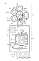
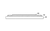
図1は、基板貼り合わせ装置10の全体構成図である。基板貼り合わせ装置10は、2枚の基板90、90を貼り合わせて、貼り合わせ基板95を製造する。尚、基板貼り合わせ装置10が、一度に3枚以上の基板90を貼り合わせて、貼り合わせ基板95を製造してもよい。   FIG. 1 is an overall configuration diagram of the substrate bonding apparatus 10. The substrate bonding apparatus 10 manufactures a bonded substrate 95 by bonding two substrates 90 and 90 together. The substrate bonding apparatus 10 may manufacture the bonded substrate 95 by bonding three or more substrates 90 at a time.

図1に示すように、基板貼り合わせ装置10は、大気環境部14と、真空環境部16と、制御部18とを備える。   As shown in FIG. 1, the substrate bonding apparatus 10 includes an air environment unit 14, a vacuum environment unit 16, and a control unit 18.

大気環境部14は、環境チャンバ12と、複数の基板カセット20と、基板ホルダラック22と、ロボットアーム24と、プリアライナ26と、アライナ28と、ロボットアーム30とを有する。環境チャンバ12は、大気環境部14を囲むように形成されている。   The atmospheric environment unit 14 includes an environment chamber 12, a plurality of substrate cassettes 20, a substrate holder rack 22, a robot arm 24, a pre-aligner 26, an aligner 28, and a robot arm 30. The environmental chamber 12 is formed so as to surround the atmospheric environment unit 14.

基板カセット20は、基板貼り合わせ装置10において貼り合わされる基板90及び貼り合わされた貼り合わせ基板95を収容する。基板貼り合わせ装置10によって貼り合わされる基板90は、単体のシリコンウエハ、化合物半導体ウエハ、ガラス基板等の他、それらに素子、回路、端子等が形成されていてもよい。   The substrate cassette 20 accommodates the substrate 90 and the bonded substrate 95 bonded together in the substrate bonding apparatus 10. The substrate 90 to be bonded by the substrate bonding apparatus 10 may be formed with elements, circuits, terminals, and the like in addition to a single silicon wafer, a compound semiconductor wafer, a glass substrate, and the like.

基板ホルダラック22は、一対の基板90が重ね合わされた重ね合わせ基板92及び貼り合わせ基板95を上下方向から保持する複数対の基板ホルダ94を収容する。基板ホルダ94は、基板90を静電吸着により保持する。   The substrate holder rack 22 accommodates a plurality of pairs of substrate holders 94 that hold the stacked substrate 92 and the bonded substrate 95 on which the pair of substrates 90 are stacked from above and below. The substrate holder 94 holds the substrate 90 by electrostatic adsorption.

ロボットアーム24は、基板カセット20に装填されている基板90をプリアライナ26に搬送する。ロボットアーム24は、プリアライナ26の基板90を、後述するアライナ28の移動ステージ38に載置された基板ホルダ94へと搬送する。ロボットアーム24は、貼り合わされた後、移動ステージ38まで搬送された貼り合わせ基板95を基板カセット20の何れかに搬送する。   The robot arm 24 transports the substrate 90 loaded in the substrate cassette 20 to the pre-aligner 26. The robot arm 24 conveys the substrate 90 of the pre-aligner 26 to the substrate holder 94 placed on the moving stage 38 of the aligner 28 described later. After being bonded, the robot arm 24 transfers the bonded substrate 95 transferred to the moving stage 38 to one of the substrate cassettes 20.

プリアライナ26は、アライナ28に基板90を装填する場合に、高精度であるがゆえに、狭いアライナ28の調整範囲にそれぞれの基板90が装填されるように、個々の基板90の位置を仮合わせする。これにより、アライナ28における基板90の位置決めが、迅速且つ正確にできる。   The pre-aligner 26 temporarily aligns the positions of the individual substrates 90 so that each substrate 90 is loaded in the narrow adjustment range of the aligner 28 because of the high accuracy when the substrates 90 are loaded on the aligner 28. . Thereby, the positioning of the substrate 90 in the aligner 28 can be performed quickly and accurately.

アライナ28は、ロボットアーム24とロボットアーム30との間に配置されている。アライナ28は、枠体34と、固定ステージ36と、移動ステージ38と、一対のシャッタ40及びシャッタ42とを有する。   The aligner 28 is disposed between the robot arm 24 and the robot arm 30. The aligner 28 includes a frame body 34, a fixed stage 36, a moving stage 38, and a pair of shutters 40 and a shutter 42.

枠体34は、固定ステージ36及び移動ステージ38を囲むように形成されている。枠体34の基板カセット20側の面と、真空環境部16側の面には、基板90、重ね合わせ基板92及び貼り合わせ基板95を搬入及び搬出可能に、開口が形成されている。   The frame 34 is formed so as to surround the fixed stage 36 and the moving stage 38. Openings are formed in the surface of the frame 34 on the substrate cassette 20 side and the surface on the vacuum environment unit 16 side so that the substrate 90, the superimposed substrate 92, and the bonded substrate 95 can be carried in and out.

固定ステージ36の下面は、基板90を保持した状態で、ロボットアーム30により移動ステージ38から搬送される基板ホルダ94を真空吸着する。   The lower surface of the fixed stage 36 vacuum-sucks the substrate holder 94 conveyed from the moving stage 38 by the robot arm 30 while holding the substrate 90.

移動ステージ38の上面は、基板90及び基板ホルダ94を真空吸着する。移動ステージ38は、枠体34の内部を水平方向及び鉛直方向に移動する。これにより、移動ステージ38が移動することによって、固定ステージ36に保持された基板90及び基板ホルダ94と、移動ステージ38に保持された基板90及び基板ホルダ94とが位置合わせされ、重ね合わされた状態で仮接合される。基板90と基板90は、接着剤によって仮接合してもよく、プラズマによって仮接合してもよい。   The upper surface of the moving stage 38 vacuum-sucks the substrate 90 and the substrate holder 94. The moving stage 38 moves in the horizontal direction and the vertical direction inside the frame body 34. Accordingly, the substrate 90 and the substrate holder 94 held on the fixed stage 36 and the substrate 90 and the substrate holder 94 held on the moving stage 38 are aligned and overlapped by the movement of the moving stage 38. Is temporarily joined. The substrate 90 and the substrate 90 may be temporarily bonded with an adhesive or may be temporarily bonded with plasma.

シャッタ40は、枠体34の基板カセット20側の開口を開閉する。シャッタ42は、枠体34の真空環境部16側の開口を開閉する。枠体34及びシャッタ40、42に囲まれた領域は、空気調整機等に連通されて、温度管理される。これにより、基板90と基板90との位置合わせの精度が向上する。   The shutter 40 opens and closes the opening of the frame 34 on the substrate cassette 20 side. The shutter 42 opens and closes the opening of the frame 34 on the vacuum environment unit 16 side. The area surrounded by the frame body 34 and the shutters 40 and 42 is communicated with an air conditioner or the like, and the temperature is controlled. Thereby, the accuracy of alignment between the substrate 90 and the substrate 90 is improved.

ロボットアーム30は、基板ホルダラック22に収容されている基板ホルダ94を移動ステージ38へと搬送する。ロボットアーム30は、移動ステージ38上に載置され、基板90を保持する基板ホルダ94を、裏返して固定ステージ36へと搬送する。ロボットアーム30は、移動ステージ38によって位置合わせされた一対の基板90を含む基板ホルダ94を真空吸着して、真空環境部16へと搬送する。ロボットアーム30は、貼り合わせ基板95を真空環境部16から移動ステージ38へと搬送する。   The robot arm 30 conveys the substrate holder 94 accommodated in the substrate holder rack 22 to the moving stage 38. The robot arm 30 is placed on the moving stage 38, and the substrate holder 94 holding the substrate 90 is turned over and transferred to the fixed stage 36. The robot arm 30 vacuum-sucks the substrate holder 94 including the pair of substrates 90 aligned by the moving stage 38 and conveys the substrate holder 94 to the vacuum environment unit 16. The robot arm 30 conveys the bonded substrate 95 from the vacuum environment unit 16 to the moving stage 38.

真空環境部16は、基板貼り合わせ装置10の貼り合わせ工程において、高温且つ真空状態に設定される。真空環境部16は、ロードロック室48と、一対のアクセスドア50及びゲートバルブ52と、ロボットアーム54と、3個の収容室55と、3個の加熱加圧装置56と、ロボットアーム58と、冷却室60とを備える。尚、加熱加圧装置56の個数は、3個に限定されるものではなく、適宜変更してもよい。   The vacuum environment unit 16 is set to a high temperature and a vacuum state in the bonding process of the substrate bonding apparatus 10. The vacuum environment unit 16 includes a load lock chamber 48, a pair of access doors 50 and a gate valve 52, a robot arm 54, three storage chambers 55, three heating and pressurizing devices 56, a robot arm 58, The cooling chamber 60 is provided. Note that the number of the heating and pressing devices 56 is not limited to three, and may be changed as appropriate.

ロードロック室48は、大気環境部14と真空環境部16とを連結する。ロードロック室48は、真空状態及び大気圧に設定できる。ロードロック室48の大気環境部14側及び真空環境部16側には、一対の基板ホルダ94に保持された一対の基板90を含む重ね合わせ基板92及び貼り合わせ基板95を搬送可能に開口が形成されている。   The load lock chamber 48 connects the atmospheric environment unit 14 and the vacuum environment unit 16. The load lock chamber 48 can be set to a vacuum state and an atmospheric pressure. Openings are formed in the load lock chamber 48 on the atmosphere environment unit 14 side and the vacuum environment unit 16 side so that the superimposed substrate 92 and the bonded substrate 95 including the pair of substrates 90 held by the pair of substrate holders 94 can be conveyed. Has been.

アクセスドア50は、ロードロック室48の大気環境部14側の開口を開閉する。ゲートバルブ52は、ロードロック室48の真空環境部16側の開口を開閉する。ロボットアーム54は、ロボットアーム30によりロードロック室48に搬入された重ね合わせ基板92を何れかの加熱加圧装置56へと搬入する。   The access door 50 opens and closes the opening of the load lock chamber 48 on the atmosphere environment unit 14 side. The gate valve 52 opens and closes the opening of the load lock chamber 48 on the vacuum environment unit 16 side. The robot arm 54 carries the superposed substrate 92 carried into the load lock chamber 48 by the robot arm 30 into one of the heating and pressing devices 56.

収容室55は、ゲートバルブ57を介してロボットチャンバ53と連結されている。収容室55は、重ね合わせ基板92及び貼り合わせ基板95を搬入及び搬出するために、ゲートバルブ57を開閉する。   The storage chamber 55 is connected to the robot chamber 53 via a gate valve 57. The accommodation chamber 55 opens and closes the gate valve 57 in order to carry in and carry out the overlapping substrate 92 and the bonded substrate 95.

3個の加熱加圧装置56は、ロボットアーム54を中心として放射状に配置されている。加熱加圧装置56は、重ね合わせ基板92を加熱及び加圧可能な構成となっている。加熱加圧装置56は、ロードロック室48から搬入された重ね合わせ基板92を貼り合わせることができる。   The three heating / pressurizing devices 56 are arranged radially around the robot arm 54. The heating and pressing device 56 is configured to be able to heat and press the overlapping substrate 92. The heating and pressurizing device 56 can bond the overlapping substrate 92 carried in from the load lock chamber 48.

ロボットアーム58は、ロボットチャンバ53の中心に回動可能に配置されている。これにより、ロボットアーム58は、貼り合わせ基板95を加熱加圧装置56から冷却室60へと搬送できる。また、ロボットアーム58は、貼り合わせ基板95を冷却室60からロードロック室48へと搬送できる。   The robot arm 58 is rotatably arranged at the center of the robot chamber 53. Thereby, the robot arm 58 can convey the bonded substrate 95 from the heating and pressurizing device 56 to the cooling chamber 60. Further, the robot arm 58 can transfer the bonded substrate 95 from the cooling chamber 60 to the load lock chamber 48.

冷却室60は、冷却機能を有する。これにより、冷却室60は、ロボットアーム58によって結合された高温の貼り合わせ基板95を冷却できる。冷却室60は、ゲートバルブ57を介してロボットチャンバ53と連結されている。制御部18は、基板貼り合わせ装置10の全体の動作を制御する。   The cooling chamber 60 has a cooling function. Thereby, the cooling chamber 60 can cool the high-temperature bonded substrate board 95 coupled by the robot arm 58. The cooling chamber 60 is connected to the robot chamber 53 through a gate valve 57. The control unit 18 controls the overall operation of the substrate bonding apparatus 10.

図2から図5は、基板貼り合わせ装置10による貼り合わせ基板95の貼り合せ工程を説明する図である。貼り合わせ工程では、まず、図2に示すように、ロボットアーム30が、基板ホルダラック22から基板ホルダ94を移動ステージ38へと搬送する。ロボットアーム24は、基板カセット20の何れかからプリアライナ26を経由させて基板90を、移動ステージ38に載置された基板ホルダ94上に載置する。   2 to 5 are diagrams for explaining a bonding process of the bonded substrate 95 by the substrate bonding apparatus 10. In the bonding step, first, as shown in FIG. 2, the robot arm 30 conveys the substrate holder 94 from the substrate holder rack 22 to the moving stage 38. The robot arm 24 places the substrate 90 on the substrate holder 94 placed on the moving stage 38 via the pre-aligner 26 from any of the substrate cassettes 20.

ロボットアーム30は、基板90を保持する基板ホルダ94を移動ステージ38から固定ステージ36へと裏返して搬送する。図3に示すように、固定ステージ36は、基板90とともに基板ホルダ94をロボットアーム30から受け取った後、基板ホルダ94を真空吸着により保持する。   The robot arm 30 carries the substrate holder 94 holding the substrate 90 upside down from the moving stage 38 to the fixed stage 36. As shown in FIG. 3, the fixed stage 36 holds the substrate holder 94 by vacuum suction after receiving the substrate holder 94 together with the substrate 90 from the robot arm 30.

次に、同様の動作によって、ロボットアーム30が移動ステージ38に基板ホルダ94を搬送した後、ロボットアーム24が移動ステージ38上の基板ホルダ94に基板90を搬送する。移動ステージ38は、基板90及び基板ホルダ94を保持しつつ、基板90及び基板ホルダ94を保持する固定ステージ36の下方へと移動する。これにより、移動ステージ38の基板90と、固定ステージ36の基板90とが互いに位置決めされる。   Next, after the robot arm 30 transports the substrate holder 94 to the moving stage 38 by the same operation, the robot arm 24 transports the substrate 90 to the substrate holder 94 on the moving stage 38. The moving stage 38 moves below the fixed stage 36 that holds the substrate 90 and the substrate holder 94 while holding the substrate 90 and the substrate holder 94. As a result, the substrate 90 of the movable stage 38 and the substrate 90 of the fixed stage 36 are positioned relative to each other.

次に、図4に示すように、移動ステージ38が、上方へと移動して、移動ステージ38の基板90の上面と固定ステージ36の基板90の下面とが合わされる。この後、ロボットアーム30が、移動ステージ38上の重ね合わせ基板92をロードロック室48へと搬送する。この後、ロボットアーム54が、重ね合わせ基板92をロードロック室48から加熱加圧装置56へと搬入する。   Next, as shown in FIG. 4, the moving stage 38 moves upward, and the upper surface of the substrate 90 of the moving stage 38 and the lower surface of the substrate 90 of the fixed stage 36 are brought together. Thereafter, the robot arm 30 conveys the superimposed substrate 92 on the moving stage 38 to the load lock chamber 48. Thereafter, the robot arm 54 carries the superimposed substrate 92 from the load lock chamber 48 to the heating and pressurizing device 56.

次に、貼り合わせ段階において、加熱加圧装置56は、重ね合わせ基板92を結合温度まで加熱した後、結合温度を維持しつつ、重ね合わせ基板92を上下方向から加圧する。これにより、重ね合わせ基板92の基板90、90が、貼り合わされて貼り合わせ基板95となる。この後、ロボットアーム58が、貼り合わせ基板95を冷却室60へと搬入する。冷却室60は貼り合わせ基板95を冷却する。ロボットアーム58は冷却された貼り合わせ基板95を基板ホルダ94とともに、冷却室60からロードロック室48へと搬送する。   Next, in the bonding step, the heating and pressurizing device 56 heats the overlapping substrate 92 to the bonding temperature, and then pressurizes the overlapping substrate 92 from above and below while maintaining the bonding temperature. Thereby, the substrates 90 and 90 of the overlapping substrate 92 are bonded to become a bonded substrate 95. Thereafter, the robot arm 58 carries the bonded substrate board 95 into the cooling chamber 60. The cooling chamber 60 cools the bonded substrate board 95. The robot arm 58 transports the cooled bonded substrate 95 together with the substrate holder 94 from the cooling chamber 60 to the load lock chamber 48.

次に、ロボットアーム30が、貼り合わせ基板95をロードロック室48から移動ステージ38へと搬送する。図5に示すように、移動ステージ38上にて、ロボットアーム30により、貼り合わせ基板95が基板ホルダ94から分離される。この後、ロボットアーム24が、貼り合わせ基板95を基板カセット20の何れかに搬出する。これにより、基板貼り合わせ装置10による貼り合わせ工程が終了して、貼り合わせ基板95が完成する。この後、図5に示す点線に沿って、貼り合わせ基板95が個片化されて積層半導体装置96が完成する。   Next, the robot arm 30 conveys the bonded substrate 95 from the load lock chamber 48 to the moving stage 38. As shown in FIG. 5, the bonded substrate 95 is separated from the substrate holder 94 by the robot arm 30 on the moving stage 38. Thereafter, the robot arm 24 carries the bonded substrate board 95 to one of the substrate cassettes 20. Thereby, the bonding process by the board | substrate bonding apparatus 10 is complete | finished, and the bonded substrate board 95 is completed. After that, along the dotted line shown in FIG. 5, the laminated substrate 95 is separated into individual pieces, thereby completing the laminated semiconductor device 96.

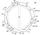
図6は、クランプ機構の一方の基板ホルダ94である上基板ホルダ100の底面図である。図7は、下方から見た上基板ホルダ100の斜視図である。図7に矢印で示す上下を上下方向とする。図6及び図7に示すように、上基板ホルダ100は、上載置部102と、上耳部104と、一対の上静電パッド106及び107と、3個の結合部108と、上給電端子120、122と、複数の上連結具112とを有する。上載置部102と、上耳部104とが第1ホルダ本体の一例である。   FIG. 6 is a bottom view of the upper substrate holder 100 which is one substrate holder 94 of the clamp mechanism. FIG. 7 is a perspective view of the upper substrate holder 100 as viewed from below. The up and down directions indicated by arrows in FIG. As shown in FIGS. 6 and 7, the upper substrate holder 100 includes an upper placement portion 102, an upper ear portion 104, a pair of upper electrostatic pads 106 and 107, three coupling portions 108, and an upper power supply terminal. 120 and 122 and a plurality of upper couplers 112. The upper placement part 102 and the upper ear part 104 are examples of the first holder body.

上載置部102は、許容応力が120MPaであって、熱膨張係数が4.5×10⁻⁶/℃のAlN等のセラミックからなる。上載置部102は、基板90よりも一回り大きい略円板状に形成されている。上載置部102の下面は、平面状に形成されている。上載置部102の下面は、上耳部104よりも下側に突出している。上載置部102の中央部の下面は、基板90が載置される載置面として機能する。 The upper mounting portion 102 is made of a ceramic such as AlN having an allowable stress of 120 MPa and a thermal expansion coefficient of 4.5 × 10 −6 / ° C. The upper placement portion 102 is formed in a substantially disk shape that is slightly larger than the substrate 90. The lower surface of the upper mounting part 102 is formed in a planar shape. The lower surface of the upper placement part 102 protrudes below the upper ear part 104. The lower surface of the central portion of the upper placement unit 102 functions as a placement surface on which the substrate 90 is placed.

上耳部104は、搬送時にロボットアーム24、30、54、58等によって支持される。上耳部104は、リング状に形成されている。上耳部104は、周方向において、分割された3個に上耳片部材124を有する。各上耳片部材124は、周方向に沿って、互いに離間して配置されている。即ち、隣接する上耳片部材124の間には間隔が形成されている。上耳部104の内周は、上載置部102の外周と略同形状に形成されている。上耳部104の内周は、上載置部102の外周縁に連結されている。また、上耳部104はロボットアーム24に代えてまたはこれに加えて、仮置き台のピンのような他の部材により支持されるのに用いられてもよい。   The upper ear 104 is supported by the robot arms 24, 30, 54, 58, etc. during transport. The upper ear portion 104 is formed in a ring shape. The upper ear portion 104 has three upper ear piece members 124 divided in the circumferential direction. The upper ear piece members 124 are arranged apart from each other along the circumferential direction. That is, a space is formed between adjacent upper ear piece members 124. The inner periphery of the upper ear portion 104 is formed in substantially the same shape as the outer periphery of the upper placement portion 102. The inner periphery of the upper ear portion 104 is connected to the outer periphery of the upper placement portion 102. Further, the upper ear 104 may be used to be supported by another member such as a pin of a temporary placing table instead of or in addition to the robot arm 24.

上耳部104の外周には、複数の切り欠き126が形成されている。切り欠き126は、複数の機能を有する。例えば、切り欠き126は、上基板ホルダ100と後述する下基板ホルダとを離脱させる押上げピンが通される。切り欠き126の周辺は、高温レーザで加工されている。これにより、加圧後、常温に戻った状態において、圧縮応力が切り欠き126の周辺に作用する。この結果、圧縮応力の変形によるひずみを切り欠き126によって吸収して、上耳部104の破損を抑制できる。   A plurality of notches 126 are formed on the outer periphery of the upper ear portion 104. The notch 126 has a plurality of functions. For example, the notch 126 is passed with a push-up pin that separates the upper substrate holder 100 and a lower substrate holder described later. The periphery of the notch 126 is processed with a high temperature laser. Thereby, in the state which returned to normal temperature after pressurization, a compressive stress acts on the periphery of the notch 126. FIG. As a result, the distortion due to the deformation of the compressive stress is absorbed by the notch 126, and damage to the upper ear portion 104 can be suppressed.

上静電パッド106は、半円形状に形成されている。上静電パッド106、107は、上載置部102の内部に埋め込まれている。一方の上静電パッド106は、上載置部102の中心を挟み、他方の上静電パッド107と線対称となるように配置されている。上給電端子120、122は、上耳部104の外周部に設けられている。上給電端子120、122は、上耳部104の上面及び下面の両面に配置されている。上給電端子120、122は、搬送中にロボットアーム24、30、54、58等に電気的に接続されて、電力が供給される。上給電端子120は、一方の上静電パッド106に電力を供給して、正の電荷をチャージする。上給電端子122は、他方の上静電パッド107に電力を供給して負の電荷をチャージする。これにより、上静電パッド106は、静電気力を発生させて、基板90を静電吸着する。   The upper electrostatic pad 106 is formed in a semicircular shape. The upper electrostatic pads 106 and 107 are embedded in the upper placement unit 102. One upper electrostatic pad 106 is disposed so as to be symmetrical with the other upper electrostatic pad 107 with the center of the upper mounting portion 102 interposed therebetween. The upper power supply terminals 120 and 122 are provided on the outer peripheral portion of the upper ear portion 104. The upper power supply terminals 120 and 122 are disposed on both the upper surface and the lower surface of the upper ear portion 104. The upper power supply terminals 120 and 122 are electrically connected to the robot arms 24, 30, 54, 58, and the like during transportation to be supplied with electric power. The upper power supply terminal 120 supplies electric power to one upper electrostatic pad 106 to charge positive charges. The upper power supply terminal 122 supplies power to the other upper electrostatic pad 107 to charge negative charges. Thus, the upper electrostatic pad 106 generates an electrostatic force and electrostatically attracts the substrate 90.

3個の結合部108は、上載置部102の外周側であって、上耳部104が途切れている個所に配置されている。3個の結合部108は、周方向において、略120°間隔で配置されている。各結合部108は、上連結部材114と、第1結合部材の一例である一対の結合部材116とを有する。上連結部材114は、平面視において、上載置部102の周方向に長い略長方形状に形成されている。上連結部材114は、上載置部102の外周部に連結されている。一対の結合部材116は、上連結部材114を介して、上載置部102に設けられている。一対の結合部材116は、結合用の永久磁石を有する。   The three coupling portions 108 are arranged on the outer peripheral side of the upper placement portion 102 and where the upper ear portion 104 is interrupted. The three coupling portions 108 are arranged at approximately 120 ° intervals in the circumferential direction. Each coupling portion 108 includes an upper coupling member 114 and a pair of coupling members 116 that are an example of a first coupling member. The upper connecting member 114 is formed in a substantially rectangular shape that is long in the circumferential direction of the upper placement portion 102 in plan view. The upper connecting member 114 is connected to the outer peripheral portion of the upper placement portion 102. The pair of coupling members 116 are provided on the upper placement portion 102 via the upper coupling member 114. The pair of coupling members 116 includes a permanent magnet for coupling.

上連結具112は、上載置部102を上耳部104に対して径方向に移動可能に付勢しつつ、上載置部102と上耳部104とを弾性を有して連結する。   The upper connector 112 elastically connects the upper placement part 102 and the upper ear part 104 while urging the upper placement part 102 to be movable in the radial direction with respect to the upper ear part 104.

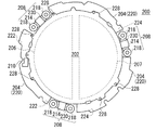
図8は、クランプ機構の他方の基板ホルダ94である下基板ホルダ200の上面図である。図9は、上方から見た下基板ホルダ200の斜視図である。図10は、挟持状態における被結合部208の近傍の拡大斜視図である。図9に矢印で示す上下を上下方向とする。図8、図9及び図10に示すように、下基板ホルダ200は、下載置部202と、下耳部204と、一対の下静電パッド206及び下静電パッド207と、3個の被結合部208、208、208と、下給電端子222、224と、下連結具228とを有する。下載置部202と、下耳部204とが第2ホルダ本体の一例である。   FIG. 8 is a top view of the lower substrate holder 200 which is the other substrate holder 94 of the clamp mechanism. FIG. 9 is a perspective view of the lower substrate holder 200 as viewed from above. FIG. 10 is an enlarged perspective view of the vicinity of the coupled portion 208 in the clamped state. The up and down directions indicated by arrows in FIG. As shown in FIGS. 8, 9 and 10, the lower substrate holder 200 includes a lower mounting portion 202, a lower ear portion 204, a pair of lower electrostatic pads 206 and a lower electrostatic pad 207, and three covered substrates. Coupling portions 208, 208, 208, lower power supply terminals 222, 224, and a lower connector 228 are included. The lower placement part 202 and the lower ear part 204 are examples of the second holder body.

下載置部202は、基板90よりも一回り大きい略円板状に形成されている。下載置部202の上面は、平面状に形成されている。下載置部202の上面は、下耳部204よりも上側に突出している。下載置部202の中央部の上面は、基板90が載置される載置面として機能する。下載置部202は、上載置部102との間で一対の基板90を挟持する。   The lower mounting portion 202 is formed in a substantially disk shape that is slightly larger than the substrate 90. The upper surface of the lower mounting part 202 is formed in a planar shape. The upper surface of the lower placement part 202 protrudes above the lower ear part 204. The upper surface of the center part of the lower mounting part 202 functions as a mounting surface on which the substrate 90 is mounted. The lower mounting unit 202 holds the pair of substrates 90 between the upper mounting unit 102.

下耳部204は、搬送時にロボットアーム24、30、54、58などによって支持される。下耳部204は、リング状に形成されている。下耳部204は、周方向において、3個に分割された下耳片部材220を有する。各下耳片部材220は、周方向に沿って、離間して配置されている。下耳部204の内周は、下載置部202の外周と略同形状に形成されている。下耳部204の内周は、下載置部202の外周に固定されている。下耳部204の外周には、切り欠き126と同様の機能を有する切り欠き210が形成されている。   The lower ear portion 204 is supported by the robot arms 24, 30, 54, 58, etc. during transportation. The lower ear portion 204 is formed in a ring shape. The lower ear portion 204 includes a lower ear piece member 220 divided into three pieces in the circumferential direction. Each lower ear piece member 220 is spaced apart along the circumferential direction. The inner periphery of the lower ear portion 204 is formed in substantially the same shape as the outer periphery of the lower placement portion 202. The inner periphery of the lower ear portion 204 is fixed to the outer periphery of the lower placement portion 202. A notch 210 having the same function as the notch 126 is formed on the outer periphery of the lower ear portion 204.

下静電パッド206は、半円形状に形成されている。下静電パッド206、207は、下載置部202の内部に埋め込まれている。一方の下静電パッド206は、下載置部202の中心を挟み、他方の下静電パッド207と線対称となるように配置されている。下給電端子222、224は、下耳部204の下面に形成されている。一方の下静電パッド206は、下給電端子222から供給される電力によって負に帯電する。他方の下静電パッド207は、下給電端子224から供給される電力によって正に帯電する。これにより、下静電パッド206は、静電気力を発生させて、基板90を静電吸着する。   The lower electrostatic pad 206 is formed in a semicircular shape. The lower electrostatic pads 206 and 207 are embedded in the lower placement unit 202. One lower electrostatic pad 206 is arranged so as to be symmetrical with the other lower electrostatic pad 207 with the center of the lower mounting portion 202 interposed therebetween. The lower power supply terminals 222 and 224 are formed on the lower surface of the lower ear portion 204. One lower electrostatic pad 206 is negatively charged by the power supplied from the lower power supply terminal 222. The other lower electrostatic pad 207 is positively charged by the power supplied from the lower power supply terminal 224. As a result, the lower electrostatic pad 206 generates an electrostatic force and electrostatically attracts the substrate 90.

3個の被結合部208は、下載置部202の外周側であって、下耳部204が途切れている個所に配置されている。3個の被結合部208は、周方向において、略120°間隔で配置されている。各被結合部208は、下連結部材214と、弾性部材の一例である一対の下弾性部材216と、第2結合部材の一例である一対の被結合部材218と、応力低減部230とを有する。   The three coupled portions 208 are arranged on the outer peripheral side of the lower placement portion 202 and at a location where the lower ear portion 204 is interrupted. The three coupled portions 208 are arranged at approximately 120 ° intervals in the circumferential direction. Each coupled portion 208 includes a lower connecting member 214, a pair of lower elastic members 216 that is an example of an elastic member, a pair of coupled members 218 that is an example of a second coupling member, and a stress reduction unit 230. .

下連結部材214は、平面視において、略正方形状に形成されている。下連結部材214は、下載置部202の外周部に連結されている。下弾性部材216は、弾性変形可能な板バネによって構成されている。下弾性部材216は、周方向に長い長方形状に形成されている。下弾性部材216の一端部は、下連結部材214に連結されている。下弾性部材216の他端部は、被結合部材218に対して上下方向の移動ができないように、被結合部材218に連結されている。これにより、下弾性部材216は、下連結部材214を介して、被結合部材218を下載置部202に連結する。   The lower connecting member 214 is formed in a substantially square shape in plan view. The lower connecting member 214 is connected to the outer peripheral portion of the lower mounting portion 202. The lower elastic member 216 is configured by an elastically deformable leaf spring. The lower elastic member 216 is formed in a rectangular shape that is long in the circumferential direction. One end of the lower elastic member 216 is connected to the lower connecting member 214. The other end of the lower elastic member 216 is coupled to the coupled member 218 so that it cannot move in the vertical direction with respect to the coupled member 218. Thereby, the lower elastic member 216 connects the member to be coupled 218 to the lower mounting portion 202 via the lower connecting member 214.

ここで、下弾性部材216は、上基板ホルダ100と下基板ホルダ200との間に挟み込まれる基板90の厚さが変化しても結合部材116と被結合部材218とを互いに結合させる。すなわち、下弾性部材216は、結合部材116と被結合部材218との結合方向に沿った相対移動を可能にさせる。ここでいう結合方向とは、基板90の法線方向である。また、下弾性部材216は、結合部材116と被結合部材218とが互いに結合した状態で上基板ホルダ100及び下基板ホルダ200同士が基板90の面方向の相対移動を拘束すべく結合部材116及び被結合部材218の面方向に沿った相対移動を拘束する。ここでいう面方向とは、基板90の面に平行な方向であって、基板90の面の法線と直交する方向である。更に、下弾性部材216は、弾性変形による反力を、上基板ホルダ100と下基板ホルダ200との間の一対の基板90を挟みこむ力として作用させる。   Here, the lower elastic member 216 couples the coupling member 116 and the coupled member 218 to each other even when the thickness of the substrate 90 sandwiched between the upper substrate holder 100 and the lower substrate holder 200 changes. That is, the lower elastic member 216 enables relative movement along the coupling direction of the coupling member 116 and the coupled member 218. The coupling direction here is the normal direction of the substrate 90. Further, the lower elastic member 216 includes the coupling member 116 and the lower substrate holder 200 so that the upper substrate holder 100 and the lower substrate holder 200 restrain relative movement in the surface direction of the substrate 90 in a state where the coupling member 116 and the coupled member 218 are coupled to each other. The relative movement along the surface direction of the coupled member 218 is restrained. The surface direction here is a direction parallel to the surface of the substrate 90 and orthogonal to the normal line of the surface of the substrate 90. Further, the lower elastic member 216 causes the reaction force due to elastic deformation to act as a force for sandwiching the pair of substrates 90 between the upper substrate holder 100 and the lower substrate holder 200.

被結合部材218は、磁石に吸着される材料、例えば、強磁性体材料を含む。被結合部材218は、下連結部材214及び下弾性部材216を介して、下載置部202に設けられている。一対の被結合部材218は、結合部材116と対向する位置に配置されている。これにより、上基板ホルダ100の下面と下基板ホルダ200の上面とが対向した状態で近接すると、被結合部材218は、結合部材116に磁力によって吸着されて、互いに結合される。この結果、上基板ホルダ100及び下基板ホルダ200によって基板90、90が保持される。この基板保持状態では、下弾性部材216は弾性変形して、上基板ホルダ100及び下基板ホルダ200から基板90、90に作用する押圧力を適切に調整する。   The coupled member 218 includes a material that is attracted to the magnet, for example, a ferromagnetic material. The coupled member 218 is provided on the lower mounting portion 202 via the lower connecting member 214 and the lower elastic member 216. The pair of members to be coupled 218 are disposed at positions facing the coupling member 116. As a result, when the lower surface of the upper substrate holder 100 and the upper surface of the lower substrate holder 200 are close to each other, the coupled members 218 are attracted to the coupling member 116 by a magnetic force and coupled to each other. As a result, the substrates 90 and 90 are held by the upper substrate holder 100 and the lower substrate holder 200. In this substrate holding state, the lower elastic member 216 is elastically deformed and appropriately adjusts the pressing force acting on the substrates 90 and 90 from the upper substrate holder 100 and the lower substrate holder 200.

応力低減部230は、下弾性部材216と同じ板バネによって構成されている。応力低減部230の厚みの一例は、0.1mmである。応力低減部230の一端部は、下連結部材214に連結されている。従って、三対の応力低減部230は、下載置部202の中心の周りに120°間隔で配置される。これにより、三対の応力低減部230は、平面視において、下載置部202及び下耳部204により構成される下基板ホルダ本体の中心の周りで点対称となる。応力低減部230の他端部は、被結合部材218に対して上下方向の移動ができないように、被結合部材218に連結されている。応力低減部230は、下連結部材214を介して、被結合部材218と下載置部202とを連結する。また、応力低減部230は、固定されていない被結合部材218に連結されているので、片持ちである。応力低減部230は、下弾性部材216よりも上方に配置されている。尚、応力低減部230は、下弾性部材216よりも下方に配置してもよい。応力低減部230は、下弾性部材216と平行に配置されている。応力低減部230と下弾性部材216との間隔の一例は、0.7mmである。尚、応力低減部230と下弾性部材216との間隔は、被結合部材218の平行度を保つために大きい方が好ましい。応力低減部230は、被結合部材218の水平方向に対する傾斜を規制する。これにより、応力低減部230は、被結合部材218を上下方向に沿って平行に移動させる。この結果、応力低減部230は、基板90を挟持するために結合部材116と被結合部材218とが結合することにより、下弾性部材216に発生する基板90の面方向の応力を低減する。   The stress reduction unit 230 is configured by the same leaf spring as the lower elastic member 216. An example of the thickness of the stress reduction part 230 is 0.1 mm. One end of the stress reduction unit 230 is coupled to the lower coupling member 214. Accordingly, the three pairs of stress reduction units 230 are arranged around the center of the lower placement unit 202 at 120 ° intervals. As a result, the three pairs of stress reduction portions 230 are point-symmetrical around the center of the lower substrate holder main body constituted by the lower placement portion 202 and the lower ear portion 204 in plan view. The other end portion of the stress reduction unit 230 is connected to the member to be coupled 218 so that it cannot move in the vertical direction with respect to the member to be coupled 218. The stress reduction unit 230 connects the coupled member 218 and the lower placement unit 202 via the lower connection member 214. Moreover, since the stress reduction part 230 is connected with the to-be-coupled member 218 which is not fixed, it is cantilever. The stress reduction unit 230 is disposed above the lower elastic member 216. The stress reduction unit 230 may be disposed below the lower elastic member 216. The stress reduction unit 230 is disposed in parallel with the lower elastic member 216. An example of the interval between the stress reduction unit 230 and the lower elastic member 216 is 0.7 mm. The distance between the stress reducing portion 230 and the lower elastic member 216 is preferably large in order to maintain the parallelism of the coupled member 218. The stress reduction unit 230 regulates the inclination of the coupled member 218 with respect to the horizontal direction. Thereby, the stress reduction unit 230 moves the coupled member 218 in parallel along the vertical direction. As a result, the stress reduction unit 230 reduces the stress in the surface direction of the substrate 90 generated in the lower elastic member 216 by coupling the coupling member 116 and the coupled member 218 in order to sandwich the substrate 90.

次に、上基板ホルダ100と下基板ホルダ200による一対の基板90の挟持について説明する。   Next, sandwiching of the pair of substrates 90 by the upper substrate holder 100 and the lower substrate holder 200 will be described.

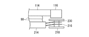
まず、応力低減部230がない場合の基板90の挟持について説明する。図11、図12及び図13は、応力低減部230がない場合の基板90の挟持について説明する図である。図11に示すように、上基板ホルダ100によって保持された基板90と、下基板ホルダ200によって保持された基板90とが位置合わせされた後、互いに接触する。これにより、図12に示すように、結合部材116が、磁力による吸着力によって、被結合部材218を引き寄せる。ここで、被結合部材218は、下弾性部材216によってのみ下連結部材214に連結されている。従って、被結合部材218は、下弾性部材216の下連結部材214側の端部を中心にして、紙面左回りに回転する。これにより、被結合部材218は、傾斜した状態で、結合部材116と接触する。この後、被結合部材218は、結合部材116との接点を中心に紙面右回りに回転する。この結果、図13に示すように、被結合部材218は、水平状態になって、結合部材116に結合される。ここで、被結合部材218が傾斜及び回転等の複雑な動きをするので、図13に示す結合状態では、下弾性部材216に歪みが生じているので、下弾性部材216に復元するための弾性力が生じる。この復元により、下弾性部材216の弾性力が応力として、被結合部材218に作用するので、基板90と基板90との相対位置がずれる。   First, the clamping of the substrate 90 when there is no stress reduction unit 230 will be described. 11, 12, and 13 are diagrams for explaining the holding of the substrate 90 when the stress reduction unit 230 is not provided. As shown in FIG. 11, the substrate 90 held by the upper substrate holder 100 and the substrate 90 held by the lower substrate holder 200 are aligned, and then contact each other. As a result, as shown in FIG. 12, the coupling member 116 draws the coupled member 218 by an attracting force due to a magnetic force. Here, the coupled member 218 is coupled to the lower coupling member 214 only by the lower elastic member 216. Accordingly, the coupled member 218 rotates counterclockwise around the end of the lower elastic member 216 on the lower coupling member 214 side. As a result, the coupled member 218 comes into contact with the coupling member 116 in an inclined state. Thereafter, the member to be coupled 218 rotates clockwise with respect to the contact point with the coupling member 116. As a result, as shown in FIG. 13, the coupled member 218 is in a horizontal state and coupled to the coupling member 116. Here, since the coupled member 218 moves in a complicated manner such as tilting and rotation, the lower elastic member 216 is distorted in the coupled state shown in FIG. Power is generated. Due to this restoration, the elastic force of the lower elastic member 216 acts on the coupled member 218 as stress, so that the relative positions of the substrate 90 and the substrate 90 shift.

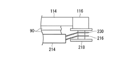
次に、本実施形態の基板90の挟持について説明する。図14、図15及び図16は、応力低減部230を有する本実施形態における基板90の挟持について説明する図である。図14に示すように、上基板ホルダ100によって保持された基板90と、下基板ホルダ200によって保持された基板90とが位置合わせされた後、互いに接触する。これにより、図15に示すように、結合部材116が、磁力による吸着力によって、被結合部材218を引き寄せる。ここで、被結合部材218は、下弾性部材216及び応力低減部230によって支持されている。これにより、被結合部材218は、水平方向の移動が規制されているので、被結合部材218は、水平状態を維持しつつ、結合部材116に接近する。この後、図16に示すように、被結合部材218の上面と結合部材116の下面とが略平行に面接触する。この結合状態において、下弾性部材216及び応力低減部230には、歪みが生じていないので、被結合部材218に応力が作用しない。この結果、基板90と基板90との相対位置の位置ずれを抑制できる。   Next, clamping of the substrate 90 of this embodiment will be described. FIGS. 14, 15, and 16 are diagrams for explaining the holding of the substrate 90 in the present embodiment having the stress reduction unit 230. As shown in FIG. 14, after the substrate 90 held by the upper substrate holder 100 and the substrate 90 held by the lower substrate holder 200 are aligned, they come into contact with each other. As a result, as shown in FIG. 15, the coupling member 116 draws the coupled member 218 by an attracting force due to a magnetic force. Here, the coupled member 218 is supported by the lower elastic member 216 and the stress reduction unit 230. Thereby, since the movement of the coupled member 218 in the horizontal direction is restricted, the coupled member 218 approaches the coupling member 116 while maintaining the horizontal state. Thereafter, as shown in FIG. 16, the upper surface of the coupled member 218 and the lower surface of the coupling member 116 are in surface contact with each other substantially in parallel. In this coupled state, the lower elastic member 216 and the stress reducing unit 230 are not distorted, so that no stress acts on the coupled member 218. As a result, the displacement of the relative position between the substrate 90 and the substrate 90 can be suppressed.

次に、上述した実施形態における応力低減部230の支持機構を変更した実施形態について説明する。図17は、支持機構を変更した応力低減部1230を有する被結合部1208の部分斜視図である。応力低減部1230は、下弾性部材216と同じ板バネからなる。図17に示すように、下弾性部材216及び応力低減部1230の一端部は、下耳片部材220の端部に連結されている。下弾性部材216及び応力低減部1230の他端部は、下連結部材214に向かって延び、被結合部材218に連結されている。応力低減部1230は、下弾性部材216と平行に設けられている。これにより、この実施形態においても、応力低減部1230が、下弾性部材216の歪みを抑制して、被結合部材218に作用する応力を低減できる。   Next, an embodiment in which the support mechanism of the stress reduction unit 230 in the above-described embodiment is changed will be described. FIG. 17 is a partial perspective view of a coupled portion 1208 having a stress reduction portion 1230 with a changed support mechanism. The stress reduction unit 1230 is made of the same leaf spring as the lower elastic member 216. As shown in FIG. 17, one end of the lower elastic member 216 and the stress reduction unit 1230 is connected to the end of the lower ear piece member 220. The other ends of the lower elastic member 216 and the stress reduction unit 1230 extend toward the lower connecting member 214 and are connected to the coupled member 218. The stress reduction unit 1230 is provided in parallel with the lower elastic member 216. Thereby, also in this embodiment, the stress reduction part 1230 can suppress the distortion of the lower elastic member 216, and can reduce the stress which acts on the to-be-joined member 218.

図18は、応力低減部330の別の実施形態を説明する被結合部308近傍の部分斜視図である。図19は、結合部108及び被結合部308の側方から見た概略図である。図18及び図19に示すように、下基板ホルダ200の被結合部308は、下弾性部材216と、被結合部材218と、応力低減部330とを有する。下弾性部材216、被結合部材218、及び、応力低減部330は、それぞれ三対ずつ下基板ホルダ200に設けられている。   FIG. 18 is a partial perspective view of the vicinity of the coupled portion 308 for explaining another embodiment of the stress reducing unit 330. FIG. 19 is a schematic view of the coupling portion 108 and the coupled portion 308 viewed from the side. As shown in FIGS. 18 and 19, the coupled portion 308 of the lower substrate holder 200 includes a lower elastic member 216, a coupled member 218, and a stress reducing unit 330. The lower elastic member 216, the coupled member 218, and the stress reduction unit 330 are provided on the lower substrate holder 200 in three pairs.

下弾性部材216は、板バネからなる。下弾性部材216の一端部は、下耳片部材220の端部に連結されている。下弾性部材216の他端部は、下連結部材214に向かって延び、被結合部材218に連結されている。   The lower elastic member 216 includes a leaf spring. One end of the lower elastic member 216 is connected to the end of the lower ear piece member 220. The other end of the lower elastic member 216 extends toward the lower connecting member 214 and is connected to the coupled member 218.

応力低減部330は、非磁性体材料からなる。応力低減部330の基板90の面方向の剛性は、下弾性部材216の基板90の面方向の剛性よりも大きい。応力低減部330の基板90の面方向と交差する方向の剛性は、下弾性部材216の基板90の面方向と交差する方向の剛性よりも小さい。応力低減部330は、板状に形成されている。応力低減部330の一端部は、下耳片部材220の端部に連結されている。一対の応力低減部330は、下連結部材214を挟み両側に配置されている。三対の応力低減部330は、平面視において、下載置部202及び下耳部204により構成される下基板ホルダ本体の中心の周りで点対称となるように、中心の周りに120°感覚で配置されている。応力低減部330の他端部は、下連結部材214に向かって延びる。応力低減部330の他端部は、いずれの構成にも連結されていない。即ち、応力低減部330は、片持ちである。応力低減部330の一部は、結合部材116と被結合部材218とが接触する面の一例である被結合部材218の上面を覆う。尚、応力低減部330は、被結合部材218の上面よりも上方に配置してもよい。この場合、基板90の面と垂直な方向において、応力低減部330のストロークを、下弾性部材216のストロークよりも小さくしてもよい。応力低減部330は、被結合部材218の上面に固定されていない。即ち、応力低減部330の他端は、下耳片部材220に連結された一端を中心に、上下方向に移動できる。応力低減部330の下面と被結合部材218の上面との間に生じる摩擦力は、応力低減部330の上面と結合部材116の下面との間に生じる摩擦力よりも小さい。   The stress reduction unit 330 is made of a nonmagnetic material. The rigidity of the stress reducing unit 330 in the surface direction of the substrate 90 is larger than the rigidity of the lower elastic member 216 in the surface direction of the substrate 90. The rigidity of the stress reduction unit 330 in the direction intersecting the surface direction of the substrate 90 is smaller than the rigidity of the lower elastic member 216 in the direction intersecting the surface direction of the substrate 90. The stress reduction unit 330 is formed in a plate shape. One end of the stress reducing unit 330 is connected to the end of the lower ear piece member 220. The pair of stress reduction portions 330 are arranged on both sides of the lower connecting member 214. The three pairs of stress reduction units 330 are 120 degrees around the center so as to be point-symmetrical around the center of the lower substrate holder main body constituted by the lower mounting unit 202 and the lower ear unit 204 in plan view. Has been placed. The other end of the stress reducing unit 330 extends toward the lower connecting member 214. The other end of the stress reduction unit 330 is not connected to any configuration. That is, the stress reduction unit 330 is cantilevered. A part of the stress reduction unit 330 covers an upper surface of the coupled member 218 that is an example of a surface on which the coupling member 116 and the coupled member 218 come into contact. Note that the stress reduction unit 330 may be disposed above the upper surface of the coupled member 218. In this case, the stroke of the stress reducing unit 330 may be smaller than the stroke of the lower elastic member 216 in the direction perpendicular to the surface of the substrate 90. The stress reduction unit 330 is not fixed to the upper surface of the coupled member 218. That is, the other end of the stress reduction unit 330 can move in the vertical direction around one end connected to the lower ear piece member 220. The frictional force generated between the lower surface of the stress reduction unit 330 and the upper surface of the coupled member 218 is smaller than the frictional force generated between the upper surface of the stress reduction unit 330 and the lower surface of the coupling member 116.

次に、図18に示す被結合部308の動作について説明する。図20及び図21は、被結合部308の動作を説明する図である。   Next, the operation of the coupled portion 308 shown in FIG. 18 will be described. 20 and 21 are diagrams illustrating the operation of the coupled portion 308. FIG.

まず、図19に示すように、上基板ホルダ100によって保持された基板90と、下基板ホルダ200によって保持された基板90とが位置合わせされた後、互いに接触する。ここで、応力低減部330は、非磁性体からなるので、基板90同士が位置合わせされるまで、結合部材116に吸着されて接触することがない。   First, as shown in FIG. 19, the substrate 90 held by the upper substrate holder 100 and the substrate 90 held by the lower substrate holder 200 are aligned, and then contact each other. Here, since the stress reduction unit 330 is made of a non-magnetic material, it is not attracted to and contacted with the coupling member 116 until the substrates 90 are aligned.

次に、図20に示すように、結合部材116が、磁力によって被結合部材218を引き寄せる。これにより、被結合部材218が、応力低減部330を介して、結合部材116に結合される。この状態では、下弾性部材216は、弾性変形して、歪みが下弾性部材216に生じる。ここで、応力低減部330の下面と被結合部材218の上面との間に生じる摩擦力は、応力低減部330の上面と結合部材116の下面との間に生じる摩擦力よりも小さい。また、応力低減部330の基板90の面方向の剛性は、下弾性部材216の基板90の面方向の剛性よりも大きい。   Next, as shown in FIG. 20, the coupling member 116 draws the coupled member 218 by magnetic force. As a result, the coupled member 218 is coupled to the coupling member 116 via the stress reduction unit 330. In this state, the lower elastic member 216 is elastically deformed and distortion occurs in the lower elastic member 216. Here, the frictional force generated between the lower surface of the stress reduction unit 330 and the upper surface of the coupled member 218 is smaller than the frictional force generated between the upper surface of the stress reduction unit 330 and the lower surface of the coupling member 116. Further, the rigidity of the stress reducing unit 330 in the surface direction of the substrate 90 is larger than the rigidity of the lower elastic member 216 in the surface direction of the substrate 90.

従って、下弾性部材216の歪みによって生じる応力によって、摩擦力が小さく、剛性の小さい被結合部材218の上面が応力低減部330の下面を摺動する。一方、結合部材116の下面は、摩擦力が大きいので、応力低減部330の上面を摺動しない。これにより、図21に示すように、下弾性部材216が復元して、応力が低減されても、被結合部材218と下載置部202との相対位置が変わるだけで、上基板ホルダ100と下基板ホルダ200との相対位置、即ち、一対の基板90同士の相対位置は変わらない。   Therefore, due to the stress generated by the distortion of the lower elastic member 216, the upper surface of the coupled member 218 having a small frictional force and small rigidity slides on the lower surface of the stress reducing unit 330. On the other hand, the lower surface of the coupling member 116 does not slide on the upper surface of the stress reduction unit 330 because the frictional force is large. As a result, as shown in FIG. 21, even if the lower elastic member 216 is restored and the stress is reduced, the relative position between the coupled member 218 and the lower mounting portion 202 is changed, so The relative position with respect to the substrate holder 200, that is, the relative position between the pair of substrates 90 does not change.

また、応力低減部330の下面と被結合部材218の上面との間に生じる摩擦力が、下弾性部材216の復元力より大きくてもよい。これにより、下弾性部材216が弾性変形しても、応力低減部330が、下弾性部材216から下載置部202に作用する応力を低減しつつ、下弾性部材216の復元を防止できる。   Further, the frictional force generated between the lower surface of the stress reducing unit 330 and the upper surface of the coupled member 218 may be larger than the restoring force of the lower elastic member 216. Thereby, even if the lower elastic member 216 is elastically deformed, the stress reduction unit 330 can prevent the lower elastic member 216 from being restored while reducing the stress acting on the lower placement unit 202 from the lower elastic member 216.

次に、図18に示す被結合部308の一部を変形した例について説明する。図22は、図18に示す被結合部308の一部を変形した被結合部1308近傍の部分斜視図である。図23は、結合部108及び被結合部1308の側方から見た概略図である。被結合部1308は、応力低減部1330以外の構成は、図18に示す被結合部308と同様の構成である。   Next, an example in which a part of the coupled portion 308 shown in FIG. 18 is modified will be described. FIG. 22 is a partial perspective view of the vicinity of the coupled part 1308 obtained by modifying a part of the coupled part 308 shown in FIG. FIG. 23 is a schematic view seen from the side of the coupling portion 108 and the coupled portion 1308. The configuration of the coupled portion 1308 is the same as that of the coupled portion 308 shown in FIG.

図22及び図23に示すように、被結合部1308の応力低減部1330は、応力低減部材1332と、補強部1334とを有する。応力低減部材1332は、上述の応力低減部330と同じ構成である。補強部1334は、応力低減部材1332の両側辺のうち、結合部材116と接する領域の両側辺に一体的に設けられている。補強部1334は、当該側辺から被結合部材218側へと延びる。補強部1334は、非磁性体からなり、応力低減部材1332の面と交差する面に平行な板状に形成されている。   As illustrated in FIGS. 22 and 23, the stress reduction portion 1330 of the coupled portion 1308 includes a stress reduction member 1332 and a reinforcement portion 1334. The stress reduction member 1332 has the same configuration as the above-described stress reduction unit 330. The reinforcing portions 1334 are integrally provided on both sides of the region in contact with the coupling member 116 among both sides of the stress reducing member 1332. The reinforcing portion 1334 extends from the side edge to the coupled member 218 side. The reinforcing portion 1334 is made of a non-magnetic material, and is formed in a plate shape parallel to a surface intersecting with the surface of the stress reducing member 1332.

補強部1334は、鉛直面と略平行に設けられている。補強部1334は、板状の応力低減部材1332を補強する。これにより、補強部1334は、応力低減部材1332の変形、特に、結合部材116と接触する領域の応力低減部材1332の変形を抑制できる。また、応力低減部材1332は、上述の応力低減部330と同様の作用及び効果を奏することができる。   The reinforcing portion 1334 is provided substantially parallel to the vertical plane. The reinforcing portion 1334 reinforces the plate-like stress reducing member 1332. Thereby, the reinforcement part 1334 can suppress the deformation | transformation of the stress reduction member 1332, especially the deformation | transformation of the stress reduction member 1332 of the area | region which contacts the coupling member 116. FIG. Further, the stress reducing member 1332 can exhibit the same operations and effects as the above-described stress reducing unit 330.

上述の実施形態では、補強部1334が、被結合部材218側へ延びるように折り曲げられているが、補強部1334は、被結合部材218とは反対側、即ち、上基板ホルダ100側へと折り曲げられていてもよい。この場合、基板90が、上基板ホルダ100及び下基板ホルダ200によって挟持される前に、下基板ホルダ200の下載置部202の上面を滑っても、補強部1334が基板90の脱落を防ぐことができる。   In the above-described embodiment, the reinforcing portion 1334 is bent so as to extend toward the coupled member 218 side. However, the reinforcing portion 1334 is folded toward the side opposite to the coupled member 218, that is, the upper substrate holder 100 side. It may be done. In this case, even if the upper surface of the lower mounting portion 202 of the lower substrate holder 200 slides before the substrate 90 is sandwiched between the upper substrate holder 100 and the lower substrate holder 200, the reinforcing portion 1334 prevents the substrate 90 from falling off. Can do.

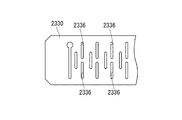
図24は、別の実施形態の被結合部2308近傍の部分斜視図である。図25は、被結合部2308の応力低減部2330の平面図である。被結合部2308の応力低減部2330以外の構成は、図18に示す被結合部2308と同様の構成である。図24に示すように、被結合部2308の応力低減部2330の一端部は、下耳片部材220に連結されている。応力低減部2330の他端部は、下連結部材214に連結されている。換言すれば、応力低減部2330は、両持ちで支持されている。応力低減部2330は、非磁性体からなり、板状に形成されている。応力低減部2330の下面と被結合部材218の上面との間に生じる摩擦力は、応力低減部2330の上面と結合部材116の下面との間に生じる摩擦力よりも小さい。   FIG. 24 is a partial perspective view of the vicinity of the coupled portion 2308 of another embodiment. FIG. 25 is a plan view of the stress reducing portion 2330 of the coupled portion 2308. The configuration of the coupled portion 2308 other than the stress reduction portion 2330 is the same as that of the coupled portion 2308 shown in FIG. As shown in FIG. 24, one end of the stress reducing portion 2330 of the coupled portion 2308 is connected to the lower ear piece member 220. The other end of the stress reducing portion 2330 is connected to the lower connecting member 214. In other words, the stress reduction part 2330 is supported by both ends. The stress reduction unit 2330 is made of a nonmagnetic material and is formed in a plate shape. The frictional force generated between the lower surface of the stress reduction unit 2330 and the upper surface of the coupled member 218 is smaller than the frictional force generated between the upper surface of the stress reduction unit 2330 and the lower surface of the coupling member 116.

ここで、図24及び図25に示すように、応力低減部2330には、複数の変形溝2336が形成されている。変形溝2336は、応力低減部2330を弾性変形の変形量を増加させる。これにより、両持ちの応力低減部2330の両端部が、弾性変形して、応力低減部2330の中央部が上下方向に移動できる。従って、被結合部材218が結合部材116に結合されると、応力低減部2330は被結合部材218の上面を覆いつつ、結合部材116の方向へと移動する。結合状態では、応力低減部2330は、被結合部材218と結合部材116との間で挟まれる。これにより、応力低減部2330は、上述の応力低減部330と同様の作用及び効果を奏することができる。   Here, as shown in FIGS. 24 and 25, the stress reducing portion 2330 is formed with a plurality of deformation grooves 2336. The deformation groove 2336 increases the amount of elastic deformation of the stress reduction unit 2330. As a result, both end portions of the two-sided stress reduction portion 2330 are elastically deformed, and the central portion of the stress reduction portion 2330 can move in the vertical direction. Therefore, when the member to be coupled 218 is coupled to the coupling member 116, the stress reduction unit 2330 moves in the direction of the coupling member 116 while covering the upper surface of the member to be coupled 218. In the coupled state, the stress reducing unit 2330 is sandwiched between the coupled member 218 and the coupling member 116. Thereby, the stress reduction part 2330 can have the same effect | action and effect as the above-mentioned stress reduction part 330. FIG.

図26は、別の実施形態の被結合部3308近傍の部分斜視図である。被結合部3308の応力低減部3330以外の構成は、図18に示す被結合部308と同様の構成である。   FIG. 26 is a partial perspective view of the vicinity of the coupled portion 3308 of another embodiment. The configuration of the coupled portion 3308 other than the stress reducing portion 3330 is the same as that of the coupled portion 308 shown in FIG.

図26に示すように、被結合部3308の応力低減部3330は、応力低減部材3332と、補強部3334とを有する。応力低減部材3332は、上述の応力低減部2330と同じ構成である。補強部3334は、応力低減部材3332の両側辺のうち、結合部材116と接する領域の両側辺に一体的に設けられている。補強部3334は、非磁性体からなり、板状に形成されている。補強部3334は、鉛直面と略平行に設けられている。補強部3334は、板状の応力低減部材3332を補強する。これにより、補強部3334は、応力低減部材3332の変形、特に、結合部材116と接触する領域の応力低減部材3332の変形を抑制できる。これにより、応力低減部3330は、上述の応力低減部2330と同様の作用及び効果を奏することができる。   As shown in FIG. 26, the stress reducing portion 3330 of the coupled portion 3308 includes a stress reducing member 3332 and a reinforcing portion 3334. The stress reducing member 3332 has the same configuration as the above-described stress reducing unit 2330. The reinforcing portions 3334 are integrally provided on both sides of the region in contact with the coupling member 116 among both sides of the stress reducing member 3332. The reinforcing portion 3334 is made of a nonmagnetic material and is formed in a plate shape. The reinforcing portion 3334 is provided substantially parallel to the vertical surface. The reinforcing portion 3334 reinforces the plate-like stress reducing member 3332. Thereby, the reinforcement part 3334 can suppress the deformation | transformation of the stress reduction member 3332, especially the deformation | transformation of the stress reduction member 3332 of the area | region which contacts the coupling member 116. FIG. Thereby, the stress reduction part 3330 can have the same effect | action and effect as the above-mentioned stress reduction part 2330.

図27は、別の実施形態の上基板ホルダ100の結合部408近傍の部分斜視図である。図28は、結合部408の分解斜視図である。図27は、上基板ホルダ100を下方から見た斜視図である。尚、本実施形態における被結合部は、図11に示すように、被結合部材218が下弾性部材216によって支持されていればよい。図27及び図28に示すように、結合部408は、結合部材416と、応力低減部430とを有する。   FIG. 27 is a partial perspective view of the vicinity of the coupling portion 408 of the upper substrate holder 100 according to another embodiment. FIG. 28 is an exploded perspective view of the coupling portion 408. FIG. 27 is a perspective view of the upper substrate holder 100 as viewed from below. In addition, the to-be-joined part in this embodiment should just have the to-be-joined member 218 supported by the lower elastic member 216, as shown in FIG. As illustrated in FIGS. 27 and 28, the coupling portion 408 includes a coupling member 416 and a stress reduction portion 430.

結合部材416は、結合用永久磁石の一例である。結合部材416は、円柱状のアルニコ磁石等の永久磁石からなる。   The coupling member 416 is an example of a coupling permanent magnet. The coupling member 416 is made of a permanent magnet such as a columnar alnico magnet.

応力低減部430は、結合部材416の結合用の磁力の強度を変化させる。応力低減部430は、保持部材446と、磁力遮断部材448と、回動部452と、低減用永久磁石部の一例である磁力遮断部材454と、軸部材438と、一対のアクチュエータ440及びアクチュエータ442とを有する。保持部材446は、磁性体からなる。保持部材446は、上耳片部材124に固定されている。保持部材446には、軸部材438が挿通される軸穴450が形成されている。   The stress reduction unit 430 changes the strength of the magnetic force for coupling of the coupling member 416. The stress reduction unit 430 includes a holding member 446, a magnetic force blocking member 448, a rotating unit 452, a magnetic force blocking member 454 that is an example of a permanent magnet unit for reduction, a shaft member 438, a pair of actuators 440 and an actuator 442. And have. The holding member 446 is made of a magnetic material. The holding member 446 is fixed to the upper ear piece member 124. A shaft hole 450 through which the shaft member 438 is inserted is formed in the holding member 446.

磁力遮断部材448は、リング状であって、ステンレスのSUS304等の非磁性体からなる。磁力遮断部材448は、保持部材446の内部に埋め込まれている。これにより、磁力遮断部材448は、磁性体で囲まれる。回動部452は、中空形状に形成された磁性体からなる。回動部452には、軸部材438が挿通される軸穴456が形成されている。回動部452は、軸部材438によって、保持部材446と連結されている。回動部452は、軸部材438の周りに回動する。従って、回動部452は、保持部材446に対して相対的に回動する。   The magnetic shielding member 448 has a ring shape and is made of a nonmagnetic material such as stainless steel SUS304. The magnetic shielding member 448 is embedded in the holding member 446. Thereby, the magnetic force blocking member 448 is surrounded by the magnetic body. The rotating part 452 is made of a magnetic body formed in a hollow shape. A shaft hole 456 through which the shaft member 438 is inserted is formed in the rotating portion 452. The rotating part 452 is connected to the holding member 446 by a shaft member 438. The rotating part 452 rotates around the shaft member 438. Accordingly, the rotating part 452 rotates relatively with respect to the holding member 446.

磁力遮断部材454は、回動部452の内部に埋め込まれている。磁力遮断部材454は、磁力遮断部材448と同じ形状のリング状である。磁力遮断部材454は、ステンレスのSUS304等の非磁性体からなる。磁力遮断部材454は、平面視において、磁力遮断部材448と中心が一致する結合位置と、磁力遮断部材448と中心がずれる解除位置との間で軸部材438の周りを回動する。即ち、結合位置では、平面視において、磁力遮断部材448と磁力遮断部材454は、同じ位置となり、解除位置では、磁力遮断部材448と磁力遮断部材454は、異なる位置となる。結合位置では、磁力遮断部材454と磁力遮断部材448の外周部に磁束が形成されて、結合部材416の結合用の磁力が作用する。一方、解除位置では、磁力遮断部材454と磁力遮断部材448とによって、結合部材416の磁束が遮断される。これにより、結合部材416の磁力が低減されて、結合部材416と被結合部材218との結合が解除される。   The magnetic force blocking member 454 is embedded in the rotation unit 452. The magnetic shielding member 454 has a ring shape that is the same shape as the magnetic shielding member 448. The magnetic shielding member 454 is made of a nonmagnetic material such as stainless steel SUS304. The magnetic shielding member 454 rotates around the shaft member 438 between a coupling position where the center coincides with the magnetic shielding member 448 and a release position where the center deviates from the magnetic shielding member 448 in plan view. That is, at the coupling position, the magnetic force blocking member 448 and the magnetic force blocking member 454 are at the same position in a plan view, and at the release position, the magnetic force blocking member 448 and the magnetic force blocking member 454 are at different positions. At the coupling position, a magnetic flux is formed on the outer peripheral portions of the magnetic shielding member 454 and the magnetic shielding member 448, and the coupling magnetic force of the coupling member 416 acts. On the other hand, in the release position, the magnetic flux of the coupling member 416 is blocked by the magnetic force blocking member 454 and the magnetic force blocking member 448. Thereby, the magnetic force of the coupling member 416 is reduced, and the coupling between the coupling member 416 and the coupled member 218 is released.

一対のアクチュエータ440、442は、移動部の一例である。一対のアクチュエータ440、442は、回動部452を軸部材438の周りで回動させる。これにより、一対のアクチュエータ440、442は、磁力遮断部材454と磁力遮断部材448との相対位置を変更する。アクチュエータ440、442には、ソレノイドアクチュエータ等を適用できる。   The pair of actuators 440 and 442 is an example of a moving unit. The pair of actuators 440 and 442 rotate the rotation unit 452 around the shaft member 438. As a result, the pair of actuators 440 and 442 change the relative positions of the magnetic force blocking member 454 and the magnetic force blocking member 448. A solenoid actuator or the like can be applied to the actuators 440 and 442.

図29、図30、図31、図32及び図33は、結合部408の動作を説明する図である。図29、図31及び図33は、側方から見た結合部408の一部断面図である。図30及び図32は、結合部408の平面図である。尚、図30及び図32においては、説明上、磁力遮断部材454は、磁力遮断部材448よりも太く記載している。   29, 30, 31, 32, and 33 are diagrams for explaining the operation of the coupling unit 408. FIG. 29, 31 and 33 are partial cross-sectional views of the coupling portion 408 as viewed from the side. 30 and 32 are plan views of the coupling portion 408. FIG. 30 and 32, the magnetic force blocking member 454 is shown to be thicker than the magnetic force blocking member 448 for the sake of explanation.

まず、図29に示すように、上基板ホルダ100と下基板ホルダ200とが、上下に配置されることにより、一対の基板90同士が向かい合わせに配置される。次に、図30及び図31に示すように、一対の基板90同士を接触させる。この状態では、磁力遮断部材448の中心と、磁力遮断部材454の中心とがずれている。これにより、磁力遮断部材448と、磁力遮断部材454とによって、結合部材416の磁束が遮断されて、磁束がほとんど外部に漏れない状態となる。   First, as shown in FIG. 29, the upper substrate holder 100 and the lower substrate holder 200 are arranged vertically so that the pair of substrates 90 are arranged facing each other. Next, as shown in FIGS. 30 and 31, the pair of substrates 90 are brought into contact with each other. In this state, the center of the magnetic force blocking member 448 is shifted from the center of the magnetic force blocking member 454. Accordingly, the magnetic flux blocking member 448 and the magnetic flux blocking member 454 block the magnetic flux of the coupling member 416 so that the magnetic flux hardly leaks to the outside.

次に、この状態で、一対の基板90同士を位置合わせする。ここで、結合部材416の磁束がほとんど出ていないので、結合部材416と被結合部材218との間に磁力はほとんど作用しない。従って、上基板ホルダ100と下基板ホルダ200とが、位置合わせする場合に、水平方向に沿って移動しても、結合部材416と被結合部材218との間に摩擦力はほとんど作用しない。従って、被結合部材218と連結された下弾性部材216に歪みが生じない。   Next, in this state, the pair of substrates 90 are aligned with each other. Here, since the magnetic flux of the coupling member 416 is hardly generated, the magnetic force hardly acts between the coupling member 416 and the coupled member 218. Therefore, when the upper substrate holder 100 and the lower substrate holder 200 are aligned, even if the upper substrate holder 100 and the lower substrate holder 200 move along the horizontal direction, the frictional force hardly acts between the coupling member 416 and the coupled member 218. Therefore, the lower elastic member 216 connected to the coupled member 218 is not distorted.

次に、図32及び図33に示すように、アクチュエータ440が、駆動して、回動部452を磁力遮断部材454とともに、軸部材438の周りに回動させる。これにより、磁力遮断部材454の中心と、磁力遮断部材448の中心とが一致して、磁力遮断部材454と磁力遮断部材448と外側に結合部材416の磁束が形成される。従って、吸着力が結合部材416と被結合部材218との間に作用する。この結果、結合部材416が被結合部材218を吸着して、一対の基板90が、上基板ホルダ100と下基板ホルダ200とによって挟持される。   Next, as shown in FIGS. 32 and 33, the actuator 440 is driven to rotate the rotating portion 452 around the shaft member 438 together with the magnetic force blocking member 454. Thereby, the center of the magnetic force blocking member 454 and the center of the magnetic force blocking member 448 coincide with each other, and the magnetic flux of the coupling member 416 is formed outside the magnetic force blocking member 454 and the magnetic force blocking member 448. Therefore, an attractive force acts between the coupling member 416 and the coupled member 218. As a result, the coupling member 416 attracts the coupled member 218, and the pair of substrates 90 is sandwiched between the upper substrate holder 100 and the lower substrate holder 200.

上述したように、本実施形態では、結合部材416の磁束が、磁力遮断部材448、454によって遮断される。これにより、応力低減部430は、下弾性部材216に生じる歪みに起因する応力を低減できる。この結果、応力低減部430は、位置合わせされた一対の基板90同士の位置ずれを抑制できる。尚、磁力遮断部材454が回動する例を示したが、磁力遮断部材454は直線的に移動させてもよい。   As described above, in this embodiment, the magnetic flux of the coupling member 416 is blocked by the magnetic force blocking members 448 and 454. Thereby, the stress reduction part 430 can reduce the stress resulting from the distortion produced in the lower elastic member 216. As a result, the stress reduction unit 430 can suppress the positional deviation between the pair of aligned substrates 90. Although the example in which the magnetic force blocking member 454 rotates is shown, the magnetic force blocking member 454 may be moved linearly.

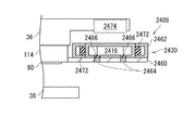
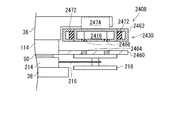
図34は、別の実施形態の結合部2408の概略図である。図34に示すように、結合部2408は、結合部材2416と、応力低減部2430とを有する。   FIG. 34 is a schematic view of a coupling portion 2408 according to another embodiment. As shown in FIG. 34, the coupling portion 2408 has a coupling member 2416 and a stress reduction portion 2430.

結合部材2416は、円柱状のアルニコ磁石等の永久磁石からなる。結合部材2416は、被結合部材218を吸着する。   The coupling member 2416 is made of a permanent magnet such as a columnar alnico magnet. The coupling member 2416 adsorbs the coupled member 218.

応力低減部2430は、固定部2460と、筐体2462と、固定用永久磁石2472と、駆動用電磁石2474と、一対の磁力遮断部材2464及び磁力遮断部材2466とを有する。   The stress reduction unit 2430 includes a fixing unit 2460, a housing 2462, a fixing permanent magnet 2472, a driving electromagnet 2474, a pair of magnetic force blocking members 2464 and a magnetic force blocking member 2466.

固定部2460は、上連結部材114に固定されている。固定部2460は、炭素鋼のS25C等の磁性体からなる。   The fixing portion 2460 is fixed to the upper connecting member 114. The fixing portion 2460 is made of a magnetic material such as carbon steel S25C.

筐体2462は、炭素鋼のS25C等の磁性体からなる。筐体2462は、中空状に形成されている。筐体2462は、結合部材2416と、固定用永久磁石2472とを収容する。筐体2462は、固定部2460に対して着脱可能に設置されている。   The housing 2462 is made of a magnetic material such as carbon steel S25C. The housing 2462 is formed in a hollow shape. The housing 2462 accommodates the coupling member 2416 and the fixing permanent magnet 2472. The housing 2462 is detachably installed on the fixing portion 2460.

固定用永久磁石2472は、磁力によって結合部材2416を固定部2460に固定する。駆動用電磁石2474は、固定ステージ36に設けられている。駆動用電磁石2474は、固定用永久磁石2472の磁力よりも強い磁力を結合部材2416に作用させる。これにより、駆動用電磁石2474は、固定用永久磁石2472とともに、結合部材2416を固定部2460から離脱させる。   The fixing permanent magnet 2472 fixes the coupling member 2416 to the fixing portion 2460 by magnetic force. The driving electromagnet 2474 is provided on the fixed stage 36. The driving electromagnet 2474 causes a magnetic force stronger than the magnetic force of the fixing permanent magnet 2472 to act on the coupling member 2416. Accordingly, the driving electromagnet 2474 causes the coupling member 2416 to be detached from the fixing portion 2460 together with the fixing permanent magnet 2472.

磁力遮断部材2464、2466は、結合部材2416と略同じ直径を有するリング状に形成されている。磁力遮断部材2464、2466は、ステンレスのSUS304等の非磁性体からなる。磁力遮断部材2464は、固定部2460に埋め込まれている。磁力遮断部材2466は、筐体2462の底面に埋め込まれている。従って、磁力遮断部材2466は、筐体2462とともに上下方向に移動する。平面視において、磁力遮断部材2466は、磁力遮断部材2464と同じ位置に配置されている。これにより、結合部材2416の磁束が、磁力遮断部材2464、2466の外側に形成されて、結合部材2416の磁力が、被結合部材218に吸着力として作用する。   The magnetic force shielding members 2464 and 2466 are formed in a ring shape having substantially the same diameter as the coupling member 2416. The magnetic shielding members 2464 and 2466 are made of a nonmagnetic material such as stainless steel SUS304. The magnetic shielding member 2464 is embedded in the fixed portion 2460. The magnetic shielding member 2466 is embedded in the bottom surface of the housing 2462. Therefore, the magnetic force shielding member 2466 moves in the vertical direction together with the housing 2462. In plan view, the magnetic force blocking member 2466 is disposed at the same position as the magnetic force blocking member 2464. Thus, the magnetic flux of the coupling member 2416 is formed outside the magnetic force blocking members 2464 and 2466, and the magnetic force of the coupling member 2416 acts on the coupled member 218 as an adsorption force.

次に、結合部2408の動作を説明する。図35から図37は、結合部2408の動作を説明する図である。まず、図34に示すように、上基板ホルダ100が、基板90とともに、固定ステージ36に搬送されて保持される。この状態では、筐体2462が結合部材2416及び固定用永久磁石2472とともに、固定部2460に保持されている。   Next, the operation of the combining unit 2408 will be described. 35 to 37 are diagrams for explaining the operation of the coupling unit 2408. FIG. First, as shown in FIG. 34, the upper substrate holder 100 is transported to and held by the fixed stage 36 together with the substrate 90. In this state, the housing 2462 is held by the fixing portion 2460 together with the coupling member 2416 and the fixing permanent magnet 2472.

次に、図35に示すように、駆動用電磁石2474を駆動させる。これにより、結合部材2416を駆動用電磁石2474に吸着させる磁力が生じるので、結合部材2416が、固定用永久磁石2472とともに、固定部2460から離脱する。この状態で、下基板ホルダ200が、基板90とともに、移動ステージ38に搬送されて保持される。   Next, as shown in FIG. 35, the driving electromagnet 2474 is driven. As a result, a magnetic force for attracting the coupling member 2416 to the driving electromagnet 2474 is generated, so that the coupling member 2416 is detached from the fixing portion 2460 together with the fixing permanent magnet 2472. In this state, the lower substrate holder 200 is transferred to the moving stage 38 and held together with the substrate 90.

次に、図36に示すように、移動ステージ38が上方に移動して、一対の基板90同士を接触させる。この状態で、移動ステージ38を水平面内で移動させて、一対の基板90同士を位置合わせする。ここで、移動ステージ38が移動しても、結合部材2416が上方に離脱しているので、結合部材2416と被結合部材218との間に吸着力が作用していない。これにより、被結合部材218を支持する下弾性部材216に歪みが生じない。換言すれば、応力低減部2430が、歪みに起因して下弾性部材216から被結合部材218に作用する応力を低減している。   Next, as shown in FIG. 36, the moving stage 38 moves upward to bring the pair of substrates 90 into contact with each other. In this state, the moving stage 38 is moved in the horizontal plane to align the pair of substrates 90 with each other. Here, even if the moving stage 38 moves, the coupling member 2416 is detached upward, so that no attracting force acts between the coupling member 2416 and the coupled member 218. Accordingly, the lower elastic member 216 that supports the coupled member 218 is not distorted. In other words, the stress reduction unit 2430 reduces the stress that acts on the coupled member 218 from the lower elastic member 216 due to distortion.

次に、図37に示すように、一対の基板90同士の位置合わせが完了すると、駆動用電磁石2474を停止させる。これにより、結合部材2416は、固定部2460に引き寄せられるので、駆動用電磁石2474から離脱する。結合部材2416が、固定部2460に結合するとともに、結合部材2416と被結合部材218とが、固定部2460を介して、磁力によって吸着される。この結果、一対の基板90が、上基板ホルダ100と下基板ホルダ200とによって挟持される。   Next, as shown in FIG. 37, when the alignment between the pair of substrates 90 is completed, the driving electromagnet 2474 is stopped. As a result, the coupling member 2416 is attracted to the fixing portion 2460, and thus is detached from the driving electromagnet 2474. The coupling member 2416 is coupled to the fixing portion 2460, and the coupling member 2416 and the member to be coupled 218 are adsorbed by the magnetic force through the fixing portion 2460. As a result, the pair of substrates 90 is sandwiched between the upper substrate holder 100 and the lower substrate holder 200.

図38は、別の応力低減部530を説明する概略図である。図38に示すように、応力低減部530は、磁力制御用電磁石の一例であるコイル部580と、応力制御部582と、冷却部584と、ロードセル586とを有する。   FIG. 38 is a schematic diagram illustrating another stress reduction unit 530. As illustrated in FIG. 38, the stress reduction unit 530 includes a coil unit 580 that is an example of a magnetic force control electromagnet, a stress control unit 582, a cooling unit 584, and a load cell 586.

コイル部580は、被結合部材218の外周部に巻かれている。コイル部580は、電力が供給されると、結合部材116から発生する結合用の磁力を低減させる磁力を発生させる。これにより、コイル部580は、結合部材116と被結合部材218との間の吸着力を低減させる。また、コイル部580は、結合用の磁力を増加させる磁力を発生させる。これにより、コイル部580は、結合部材116と被結合部材218との間の吸着力を増加させる。   The coil portion 580 is wound around the outer peripheral portion of the coupled member 218. When power is supplied, the coil unit 580 generates a magnetic force that reduces the magnetic force for coupling generated from the coupling member 116. Thereby, the coil part 580 reduces the attractive force between the coupling member 116 and the coupled member 218. In addition, the coil unit 580 generates a magnetic force that increases the magnetic force for coupling. Thereby, the coil part 580 increases the attractive force between the coupling member 116 and the coupled member 218.

ロードセル586は、被結合部材218を支持する。ロードセル586に被結合部材218が載置されると、ロードセル586は、被結合部材218による負荷を検出する。この状態で、結合部材116が被結合部材218に接近すると、被結合部材218が結合部材116に引き寄せられるので、ロードセル586に作用する負荷が低減する。これにより、ロードセル586は、結合部材116の磁力を検出する。冷却部584は、磁力を発生させるための電力が供給されているコイル部580を冷却する。   The load cell 586 supports the coupled member 218. When the coupled member 218 is placed on the load cell 586, the load cell 586 detects a load applied by the coupled member 218. In this state, when the coupling member 116 approaches the coupled member 218, the coupled member 218 is attracted to the coupling member 116, so that the load acting on the load cell 586 is reduced. As a result, the load cell 586 detects the magnetic force of the coupling member 116. The cooling unit 584 cools the coil unit 580 to which power for generating magnetic force is supplied.

応力制御部582は、コイル部580と接続及び離脱可能に構成されている。応力制御部582は、冷却部584及びロードセル586と接続されている。これにより、応力制御部582は、コイル部580と、冷却部584と、ロードセル586とを制御する。例えば、応力制御部582は、コイル部580の磁力を制御する。   The stress control unit 582 is configured to be connected to and disconnected from the coil unit 580. The stress control unit 582 is connected to the cooling unit 584 and the load cell 586. Thus, the stress control unit 582 controls the coil unit 580, the cooling unit 584, and the load cell 586. For example, the stress control unit 582 controls the magnetic force of the coil unit 580.

応力低減部530では、基板90同士の位置合わせが完了するまでは、応力制御部582がコイル部580に電力を供給するとともに、冷却部584を駆動させてコイル部580を冷却する。これにより、結合部材116と被結合部材218との間の磁力が、コイル部580から生じる磁力によってキャンセルされる。この結果、結合部材116と被結合部材218との間に吸着力が発生しないので、結合部材116は、被結合部材218を吸着しない。従って、被結合部材218は、結合部材116に対して自由に移動できるので、位置合わせの間、下基板ホルダ200を移動させても、下弾性部材216に歪みが生じない。この後、基板90同士の位置合わせが完了すると、応力制御部582は、コイル部580の電力を徐々に弱くする。これにより、コイル部580の磁力によりキャンセルされる結合部材116の磁力が徐々に少なくなり、被結合部材218と結合する結合部材116の吸着力が徐々に強くなる。これにより、結合部材116が被結合部材218と結合する。ここで、吸着力が徐々に強くなるので、結合部材116と被結合部材218との間が離脱している状態から結合されても、結合による下弾性部材216の歪みが生じ難い。従って、歪みに起因する下弾性部材216の応力を低減できる。換言すれば、応力低減部530は、コイル部580を制御することにより、下弾性部材216の応力を低減している。   In the stress reduction unit 530, the stress control unit 582 supplies power to the coil unit 580 and drives the cooling unit 584 to cool the coil unit 580 until alignment between the substrates 90 is completed. Thereby, the magnetic force between the coupling member 116 and the member to be coupled 218 is canceled by the magnetic force generated from the coil portion 580. As a result, since no attracting force is generated between the coupling member 116 and the coupled member 218, the coupling member 116 does not attract the coupled member 218. Therefore, since the coupled member 218 can freely move with respect to the coupling member 116, even if the lower substrate holder 200 is moved during alignment, the lower elastic member 216 is not distorted. Thereafter, when the alignment between the substrates 90 is completed, the stress control unit 582 gradually weakens the power of the coil unit 580. Thereby, the magnetic force of the coupling member 116 canceled by the magnetic force of the coil portion 580 gradually decreases, and the attractive force of the coupling member 116 coupled to the coupled member 218 gradually increases. As a result, the coupling member 116 is coupled to the coupled member 218. Here, since the attracting force gradually increases, even if the coupling member 116 and the coupled member 218 are separated from each other, the lower elastic member 216 is hardly distorted by the coupling. Therefore, the stress of the lower elastic member 216 due to strain can be reduced. In other words, the stress reduction unit 530 reduces the stress of the lower elastic member 216 by controlling the coil unit 580.

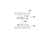
図39は、別の下弾性部材616及び被結合部材618を説明する図である。図40は、下弾性部材616の平面図である。図41は、被結合部材618の分解図である。   FIG. 39 is a diagram illustrating another lower elastic member 616 and a member 618 to be coupled. FIG. 40 is a plan view of the lower elastic member 616. FIG. 41 is an exploded view of the coupled member 618.

図39及び図40に示すように、下弾性部材616は、長手方向に延びる摺動溝617が形成されている。   As shown in FIGS. 39 and 40, the lower elastic member 616 has a sliding groove 617 extending in the longitudinal direction.

図39及び図41に示すように、被結合部材618は、上被結合部位620と、下被結合部位622と、連結軸624とを有する。   As shown in FIGS. 39 and 41, the member to be coupled 618 includes an upper coupled part 620, a lower coupled part 622, and a connecting shaft 624.

上被結合部位620の上部は、円板状に形成されている。上被結合部位620の上部以外には、円筒状の上円筒部626が形成されている。上円筒部626の外径は、摺動溝617の幅よりも大きい。上被結合部位620の下部には、嵌入部628が形成されている。嵌入部628は、下被結合部位622に嵌入される。また、嵌入部628は、摺動溝617に挿通される。嵌入部628の直径は、摺動溝617の幅と略同じである。上被結合部位620の側面には、上連結溝630が形成されている。   The upper part of the upper coupled portion 620 is formed in a disc shape. A cylindrical upper cylindrical portion 626 is formed in addition to the upper portion of the upper coupled portion 620. The outer diameter of the upper cylindrical portion 626 is larger than the width of the sliding groove 617. A fitting portion 628 is formed in the lower portion of the upper coupled portion 620. The fitting portion 628 is fitted into the lower joint portion 622. Further, the fitting portion 628 is inserted through the sliding groove 617. The diameter of the fitting portion 628 is substantially the same as the width of the sliding groove 617. An upper connection groove 630 is formed on a side surface of the upper coupled portion 620.

下被結合部位622の下部は、円板状に形成されている。下被結合部位622の下部以外には、円筒状の下円筒部632が形成されている。下円筒部632の外径は、上円筒部626の外径と同じであって、摺動溝617の幅よりも大きい。下被結合部位622には、上連結溝630と連続する下連結溝634が形成されている。   The lower part of the lower joint part 622 is formed in a disk shape. A cylindrical lower cylindrical portion 632 is formed in addition to the lower portion of the lower portion to be coupled 622. The outer diameter of the lower cylindrical portion 632 is the same as the outer diameter of the upper cylindrical portion 626 and is larger than the width of the sliding groove 617. A lower coupling groove 634 that is continuous with the upper coupling groove 630 is formed in the lower coupling portion 622.

連結軸624は、上連結溝630及び下連結溝634に挿通される。これにより、連結軸624は、上被結合部位620と下被結合部位622とが離脱することを抑制しつつ、上被結合部位620と下被結合部位622とを上下方向に相対移動可能に連結する。   The connection shaft 624 is inserted through the upper connection groove 630 and the lower connection groove 634. Thus, the connecting shaft 624 connects the upper coupled site 620 and the lower coupled site 622 so as to be movable relative to each other in a vertical direction while suppressing the upper coupled site 620 and the lower coupled site 622 from separating. To do.

図42は、非結合状態における被結合部材618の側面図である。図43は、結合状態における被結合部材618の側面図である。   FIG. 42 is a side view of the member 618 to be coupled in the uncoupled state. FIG. 43 is a side view of the coupled member 618 in the coupled state.

図42に示すように、非結合状態では、自重によって、下被結合部位622が、上被結合部位620に対して下限位置に配置されている。この後、結合部材116が被結合部材618に接近すると、被結合部材618は、下弾性部材616の摺動溝617を摺動しつつ、結合部材116に磁力により吸着される。すなわち、被結合部材618が結合部材116に吸着されるまでは、被結合部材618と下弾性部材616とが、互いに相対移動できる。被結合部材618が結合部材116に接すると、上被結合部位620は停止するが、下被結合部位622は更に結合部材116に吸着される。これにより、図43に示すように、嵌入部628が、更に下被結合部位622に嵌入されるので、上円筒部626の下面と下円筒部632の上面とによって、下弾性部材616が挟持される。この結果、被結合部材618が下弾性部材616に固定される。すなわち、被結合部材618が結合部材116に吸着されて結合した後は、被結合部材618と下弾性部材616との相対移動が不可になる。ここで、被結合部材618は、下弾性部材616を摺動しつつ、結合されるので、下弾性部材616に歪みが生じない。これにより、下弾性部材616の応力を低減できる。この実施形態では、下弾性部材616と被結合部材618が、応力低減部を兼ねるといえる。   As shown in FIG. 42, in the unbound state, the lower bound site 622 is disposed at the lower limit position with respect to the upper bound site 620 by its own weight. Thereafter, when the coupling member 116 approaches the coupled member 618, the coupled member 618 is attracted to the coupling member 116 by magnetic force while sliding on the sliding groove 617 of the lower elastic member 616. That is, until the coupled member 618 is attracted to the coupling member 116, the coupled member 618 and the lower elastic member 616 can move relative to each other. When the coupled member 618 contacts the coupling member 116, the upper coupled site 620 stops, but the lower coupled site 622 is further adsorbed by the coupling member 116. Accordingly, as shown in FIG. 43, the fitting portion 628 is further fitted into the lower coupled portion 622, so that the lower elastic member 616 is sandwiched between the lower surface of the upper cylindrical portion 626 and the upper surface of the lower cylindrical portion 632. The As a result, the coupled member 618 is fixed to the lower elastic member 616. That is, after the coupled member 618 is attracted to and coupled to the coupling member 116, the relative movement between the coupled member 618 and the lower elastic member 616 becomes impossible. Here, since the coupled member 618 is coupled while sliding on the lower elastic member 616, the lower elastic member 616 is not distorted. Thereby, the stress of the lower elastic member 616 can be reduced. In this embodiment, it can be said that the lower elastic member 616 and the coupled member 618 also serve as a stress reduction unit.

上述した各実施形態の構成の形状、配置、個数、材料、数値等は適宜変更してよい。また、各実施形態を適宜組み合わせてもよい。例えば、下弾性部材の枚数は適宜変更してよい。   The shape, arrangement, number, material, numerical value and the like of the configuration of each embodiment described above may be changed as appropriate. Moreover, you may combine each embodiment suitably. For example, the number of lower elastic members may be changed as appropriate.

図18から図26における応力低減部は、上基板ホルダ100に設けてもよい。平板状の基板ホルダを例にあげたが、いずれか一方または両方がリング状の基板ホルダに上述の実施形態を適用してもよい。また、結合部材と被結合部材は、真空吸着、分子間力、および、接着剤等によって結合させてもよく、それらの組み合わせによって結合させてもよい。   The stress reduction unit in FIGS. 18 to 26 may be provided in the upper substrate holder 100. Although the flat substrate holder is taken as an example, one or both of the embodiments may be applied to a ring-shaped substrate holder. Further, the coupling member and the member to be coupled may be coupled by vacuum adsorption, intermolecular force, an adhesive, or the like, or may be coupled by a combination thereof.

以上、本発明を実施の形態を用いて説明したが、本発明の技術的範囲は上記実施の形態に記載の範囲には限定されない。上記実施の形態に、多様な変更または改良を加えることが可能であることが当業者に明らかである。その様な変更または改良を加えた形態も本発明の技術的範囲に含まれ得ることが、特許請求の範囲の記載から明らかである。   As mentioned above, although this invention was demonstrated using embodiment, the technical scope of this invention is not limited to the range as described in the said embodiment. It will be apparent to those skilled in the art that various modifications or improvements can be added to the above-described embodiment. It is apparent from the scope of the claims that the embodiments added with such changes or improvements can be included in the technical scope of the present invention.

特許請求の範囲、明細書、および図面中において示した装置、システム、プログラム、および方法における動作、手順、ステップ、および段階等の各処理の実行順序は、特段「より前に」、「先立って」等と明示しておらず、また、前の処理の出力を後の処理で用いるのでない限り、任意の順序で実現しうることに留意すべきである。特許請求の範囲、明細書、および図面中の動作フローに関して、便宜上「まず、」、「次に、」等を用いて説明したとしても、この順で実施することが必須であることを意味するものではない。   The order of execution of each process such as operations, procedures, steps, and stages in the apparatus, system, program, and method shown in the claims, the description, and the drawings is particularly “before” or “prior to”. It should be noted that the output can be realized in any order unless the output of the previous process is used in the subsequent process. Regarding the operation flow in the claims, the description, and the drawings, even if it is described using “first”, “next”, etc. for convenience, it means that it is essential to carry out in this order. It is not a thing.

10 基板貼り合わせ装置、 12 環境チャンバ、 14 大気環境部、 16 真空環境部、 18 制御部、 20 基板カセット、 22 基板ホルダラック、 24 ロボットアーム、 26 プリアライナ、 28 アライナ、 30 ロボットアーム、 34 枠体、 36 固定ステージ、 38 移動ステージ、 40 シャッタ、 42 シャッタ、 48 ロードロック室、 50 アクセスドア、 52 ゲートバルブ、 53 ロボットチャンバ、 54 ロボットアーム、 55 収容室、 56 加熱加圧装置、 57 ゲートバルブ、 58 ロボットアーム、 60 冷却室、 90 基板、 92 重ね合わせ基板、 94 基板ホルダ、 95 貼り合わせ基板、 96 積層半導体装置、 100 上基板ホルダ、 102 上載置部、 104 上耳部、 106 上静電パッド、 107 上静電パッド、 108 結合部、 112 上連結具、 114 上連結部材、 116 結合部材、 120 上給電端子、 122 上給電端子、 124 上耳片部材、 126 切り欠き、 200 下基板ホルダ、 202 下載置部、 204 下耳部、 206 下静電パッド、 207 下静電パッド、 208 被結合部、 210 切り欠き、 214 下連結部材、 216 下弾性部材、 218 被結合部材、 220 下耳片部材、 222 下給電端子、 224 下給電端子、 228 下連結具、 230 応力低減部、 308 被結合部、 330 応力低減部、 408 結合部、 416 結合部材、 430 応力低減部、 438 軸部材、 440 アクチュエータ、 442 アクチュエータ、 446 保持部材、 448 磁力遮断部材、 450 軸穴、 452 回動部、 454 磁力遮断部材、 456 軸穴、 530 応力低減部、 580 コイル部、 582 応力制御部、 584 冷却部、 586 ロードセル、 616 下弾性部材、 617 摺動溝、 618 被結合部材、 620 上被結合部位、 622 下被結合部位、 624 連結軸、 626 上円筒部、 628 嵌入部、 630 上連結溝、 632 下円筒部、 634 下連結溝、 1208 被結合部、 1230 応力低減部、 1308 被結合部、 1330 応力低減部、 1332 応力低減部材、 1334 補強部、 2308 被結合部、 2330 応力低減部、 2336 変形溝、 2408 結合部、 2416 結合部材、 2430 応力低減部、 2460 固定部、 2462 筐体、 2464 磁力遮断部材、 2466 磁力遮断部材、 2472 固定用永久磁石、 2474 駆動用電磁石、 3308 被結合部、 3330 応力低減部、 3332 応力低減部材、 3334 補強部   DESCRIPTION OF SYMBOLS 10 Board | substrate bonding apparatus, 12 Environmental chamber, 14 Atmospheric environment part, 16 Vacuum environment part, 18 Control part, 20 Substrate cassette, 22 Substrate holder rack, 24 Robot arm, 26 Pre-aligner, 28 aligner, 30 Robot arm, 34 Frame , 36 fixed stage, 38 moving stage, 40 shutter, 42 shutter, 48 load lock chamber, 50 access door, 52 gate valve, 53 robot chamber, 54 robot arm, 55 receiving chamber, 56 heating and pressurizing device, 57 gate valve, 58 robot arm, 60 cooling chamber, 90 substrate, 92 superimposed substrate, 94 substrate holder, 95 bonded substrate, 96 laminated semiconductor device, 100 Upper substrate holder, 102 Upper placement part, 104 Upper ear part, 106 Upper electrostatic pad, 107 Upper electrostatic pad, 108 Coupling part, 112 Upper coupling tool, 114 Upper coupling member, 116 Coupling member, 120 Upper power supply terminal, 122 Upper feeding terminal, 124 Upper ear piece member, 126 Notch, 200 Lower substrate holder, 202 Lower mounting portion, 204 Lower ear portion, 206 Lower electrostatic pad, 207 Lower electrostatic pad, 208 Coupled portion, 210 Notch, 214 lower connecting member, 216 lower elastic member, 218 coupled member, 220 lower ear piece member, 222 lower feeding terminal, 224 lower feeding terminal, 228 lower coupling tool, 230 stress reducing portion, 308 coupled portion, 330 stress reducing portion , 408 joint, 416 joint Material, 430 Stress reducing part, 438 Shaft member, 440 Actuator, 442 Actuator, 446 Holding member, 448 Magnetic shielding member, 450 Shaft hole, 452 Rotating part, 454 Magnetic shielding member, 456 Shaft hole, 530 Stress reducing part, 580 Coil part, 582 Stress control part, 584 Cooling part, 586 Load cell, 616 Lower elastic member, 617 Sliding groove, 618 Member to be joined, 620 Upper part to be joined, 622 Lower part to be joined, 624 Connecting shaft, 626 Upper cylindrical part , 628 fitting part, 630 upper connecting groove, 632 lower cylindrical part, 634 lower connecting groove, 1208 coupled part, 1230 stress reducing part, 1308 coupled part, 1330 stress reducing part, 1332 stress reducing member, 1 334 Reinforcement part, 2308 To-be-joined part, 2330 Stress reduction part, 2336 Deformation groove, 2408 Coupling part, 2416 Coupling member, 2430 Stress reduction part, 2460 Fixing part, 2462 Housing, 2464 Magnetic shielding member, 2466 Magnetic shielding member Permanent magnet for fixing, 2474 electromagnet for driving, 3308 coupled portion, 3330 stress reducing portion, 3332 stress reducing member, 3334 reinforcing portion

Claims (14)

基板を載置するホルダ本体と、
前記ホルダ本体に弾性部材を介して連結され、前記ホルダ本体との間で前記基板を保持する他の基板ホルダに結合される結合部材と、
前記結合部材の結合状態において、前記結合部材の結合時に前記弾性部材に生じた応力を低減する応力低減部と、
を備える基板ホルダ。
A holder body for placing a substrate;
A coupling member coupled to the holder body via an elastic member and coupled to another substrate holder that holds the substrate between the holder body ;
A stress reduction unit that reduces stress generated in the elastic member when the coupling member is coupled in the coupled state of the coupling member;
A substrate holder comprising:
前記応力低減部は、前記弾性部材を前記他の基板ホルダに対して相対移動させることにより前記応力を低減する請求項1に記載の基板ホルダ。  The substrate holder according to claim 1, wherein the stress reduction unit reduces the stress by moving the elastic member relative to the other substrate holder. 前記応力低減部は、前記ホルダ本体に一端が連結され、一部が前記結合部材の結合面を覆う板状の応力低減部材を有し
前記結合部材は、前記結合面と前記他の基板ホルダとの間に前記応力低減部材を挟み込んで前記他の基板ホルダと結合し、
前記応力低減部材と前記結合面との間の摩擦力は、前記応力低減部材と前記他の基板ホルダの結合部材との間の摩擦力よりも小さい請求項2に記載の基板ホルダ。
The stress reduction portion, prior SL is connected at one end to the holder body has a plate-shaped stress reducing member covering the coupling surface of part of the coupling member,
The coupling member is coupled to the other substrate holder by sandwiching the stress reducing member between the coupling surface and the other substrate holder,
The substrate holder according to claim 2, wherein a frictional force between the stress reducing member and the coupling surface is smaller than a frictional force between the stress reducing member and the coupling member of the other substrate holder.
記応力低減部は、複数の前記応力低減部材を有し、
複数の前記応力低減部材は、平面視において、前記ホルダ本体の中心の周りで点対称となるように配置されている請求項3に記載の基板ホルダ。
Before SL stress reduction portion includes a plurality of said stress reducing member,
The substrate holder according to claim 3, wherein the plurality of stress reducing members are arranged so as to be point symmetric around the center of the holder body in a plan view.
前記応力低減部は、前記応力低減部材の側辺に設けられ、前記応力低減部材と交差する板状の補強部を有する請求項3または4に記載の基板ホルダ。 5. The substrate holder according to claim 3 , wherein the stress reduction portion includes a plate-like reinforcing portion that is provided on a side of the stress reduction member and intersects the stress reduction member. 複数の前記応力低減部材のそれぞれは、片持ちである請求項3から5のいずれか1項に記載の基板ホルダ。 Each of the plurality of the stress reducing member, the substrate holder according to any one of claims 3 to 5 which is cantilevered. 前記結合部材は、磁力を発生させる結合用磁石を有する請求項1から6のいずれか1項に記載の基板ホルダ。 The substrate holder according to claim 1 , wherein the coupling member includes a coupling magnet that generates a magnetic force. 前記応力低減部は、前記他の基板ホルダの前記結合部材に作用する前記磁力の強度を変化させる請求項7に記載の基板ホルダ。 The substrate holder according to claim 7 , wherein the stress reduction unit changes the strength of the magnetic force acting on the coupling member of the other substrate holder. 前記応力低減部は、前記他の基板ホルダの前記結合部材に前記磁力を作用させる前記結合用磁石の磁束を遮断する第1磁力遮断部材と、前記磁束を外部に形成して前記結合部材の前記他の基板ホルダの前記結合部材との結合位置と、前記磁束を遮断して結合を解除する解除位置との間で前記第1磁力遮断部材を移動させる移動部とを有する請求項8に記載の基板ホルダ。 The stress reduction unit includes: a first magnetic force blocking member that blocks the magnetic flux of the coupling magnet that causes the magnetic force to act on the coupling member of the other substrate holder; and coupling positions of the coupling member of another substrate holder, according to claim 8 and a moving unit for moving the first magnetic shielding member between a release position for releasing the coupling by blocking the flux Substrate holder. 前記結合用の磁力を低減させる磁力を生じさせる磁力制御用電磁石と、前記磁力制御用電磁石の磁力を制御する応力制御部とを有する応力低減部を更に備える請求項7から9のいずれか一項に記載の基板ホルダ。 The stress reduction part which has further the stress control part which controls the magnetic force of the magnetic force control electromagnet which produces the magnetic force which reduces the magnetic force for the said coupling | bonding magnetic force, and the said magnetic force control electromagnet. A substrate holder according to claim 1. 前記磁力制御用電磁石は、前記結合用の磁力を増加させる磁力を発生させる請求項10に記載の基板ホルダ。 The substrate holder according to claim 10 , wherein the magnetic force control electromagnet generates a magnetic force that increases the coupling magnetic force. 前記結合部材は、前記他の基板ホルダの前記結合部材と真空吸着により結合する請求項1から11のいずれか1項に記載の基板ホルダ。 The substrate holder according to claim 1 , wherein the coupling member is coupled to the coupling member of the other substrate holder by vacuum suction. 請求項1から12のいずれか1項に記載の基板ホルダを備える基板貼り合わせ装置。 A substrate bonding apparatus comprising the substrate holder according to claim 1 . 基板を載置するホルダ本体および前記ホルダ本体に弾性部材を介して連結された第1結合部材を有する第1基板ホルダと、
前記第1結合部材に結合される第2結合部材を有し、前記第1基板ホルダとの間で複数の前記基板を保持する第2基板ホルダと、
前記第1結合部材と前記第2結合部材との結合状態において、前記第1結合部材および前記第2結合部材の結合時に前記弾性部材に生じた応力を低減する応力低減部と、
を有する基板ホルダ対。
A first substrate holder having a holder body for placing a substrate and a first coupling member connected to the holder body via an elastic member;
A second substrate holder having a second coupling member coupled to the first coupling member, and holding the plurality of substrates with the first substrate holder;
A stress reduction unit that reduces stress generated in the elastic member when the first coupling member and the second coupling member are coupled in the coupled state of the first coupling member and the second coupling member;
A pair of substrate holders.
JP2012074651A 2012-03-28 2012-03-28 Clamp mechanism and substrate bonding apparatus Active JP5970909B2 (en)

Priority Applications (1)

Application Number Priority Date Filing Date Title
JP2012074651A JP5970909B2 (en) 2012-03-28 2012-03-28 Clamp mechanism and substrate bonding apparatus

Applications Claiming Priority (1)

Application Number Priority Date Filing Date Title
JP2012074651A JP5970909B2 (en) 2012-03-28 2012-03-28 Clamp mechanism and substrate bonding apparatus

Publications (3)

Publication Number Publication Date
JP2013207094A JP2013207094A (en) 2013-10-07
JP2013207094A5 JP2013207094A5 (en) 2015-05-21
JP5970909B2 true JP5970909B2 (en) 2016-08-17

Family

ID=49525886

Family Applications (1)

Application Number Title Priority Date Filing Date
JP2012074651A Active JP5970909B2 (en) 2012-03-28 2012-03-28 Clamp mechanism and substrate bonding apparatus

Country Status (1)

Country Link
JP (1) JP5970909B2 (en)

Family Cites Families (3)

* Cited by examiner, † Cited by third party
Publication number Priority date Publication date Assignee Title
JP4852891B2 (en) * 2005-05-31 2012-01-11 株式会社ニコン Wafer holder, wafer stacking method, and stacked semiconductor device manufacturing method
JP5098165B2 (en) * 2005-12-08 2012-12-12 株式会社ニコン Wafer bonding method, bonding apparatus, and manufacturing method of stacked semiconductor device
JP5577585B2 (en) * 2008-11-12 2014-08-27 株式会社ニコン Substrate holding member, bonding apparatus, and bonding method

Also Published As

Publication number Publication date
JP2013207094A (en) 2013-10-07

Similar Documents

Publication Publication Date Title
JP6112016B2 (en) Substrate holder and substrate bonding apparatus
JP5979135B2 (en) Substrate laminating apparatus, substrate holding apparatus, substrate laminating method, substrate holding method, laminated semiconductor device, and superimposed substrate
KR101669045B1 (en) Substrate holding member, substrate bonding apparatus, apparatus for manufacturing multilayer substrate, substrate bonding method, method for manufacturing multilayer substrate, and method for manufacturing multilayer semiconductor device
JP6051523B2 (en) Substrate holder pair, substrate bonding apparatus, and device manufacturing method
JP2011216832A (en) Substrate overlapping device, substrate holder, substrate overlapping system, method of overlapping substrate, method of manufacturing device, and apparatus and method for joining substrate
JP5305220B2 (en) Substrate bonding device
JP5428638B2 (en) Stage device, substrate bonding apparatus, substrate bonding method, semiconductor manufacturing method, and substrate holder
JP5970909B2 (en) Clamp mechanism and substrate bonding apparatus
JP5476705B2 (en) Multilayer semiconductor manufacturing apparatus, multilayer semiconductor manufacturing method, and substrate holder rack
JP5593748B2 (en) Positioning apparatus, substrate bonding apparatus, and substrate bonding method
JP5493713B2 (en) Substrate holder, substrate bonding apparatus, substrate holder pair, and transfer apparatus
JP2012253269A (en) Substrate holder and substrate bonding apparatus
TWI836247B (en) Manufacturing method of substrate bonding device and semiconductor device
JP2012253273A (en) Substrate bonding device
JP2013026555A (en) Management device
JP2013232663A (en) Substrate holder apparatus and substrate bonding apparatus
JP5853425B2 (en) Substrate bonding equipment
JP2014222778A (en) Stage device and substrate sticking device
JP2011129777A (en) Substrate overlaying device and manufacturing method of the same

Legal Events

Date Code Title Description
A621 Written request for application examination

Free format text: JAPANESE INTERMEDIATE CODE: A621

Effective date: 20150330

A521 Request for written amendment filed

Free format text: JAPANESE INTERMEDIATE CODE: A523

Effective date: 20150407

A131 Notification of reasons for refusal

Free format text: JAPANESE INTERMEDIATE CODE: A131

Effective date: 20151013

A977 Report on retrieval

Free format text: JAPANESE INTERMEDIATE CODE: A971007

Effective date: 20151015

A521 Request for written amendment filed

Free format text: JAPANESE INTERMEDIATE CODE: A523

Effective date: 20151211

TRDD Decision of grant or rejection written
A01 Written decision to grant a patent or to grant a registration (utility model)

Free format text: JAPANESE INTERMEDIATE CODE: A01

Effective date: 20160614

A61 First payment of annual fees (during grant procedure)

Free format text: JAPANESE INTERMEDIATE CODE: A61

Effective date: 20160627

R150 Certificate of patent or registration of utility model

Ref document number: 5970909

Country of ref document: JP

Free format text: JAPANESE INTERMEDIATE CODE: R150

R250 Receipt of annual fees

Free format text: JAPANESE INTERMEDIATE CODE: R250

R250 Receipt of annual fees

Free format text: JAPANESE INTERMEDIATE CODE: R250

R250 Receipt of annual fees

Free format text: JAPANESE INTERMEDIATE CODE: R250

R250 Receipt of annual fees

Free format text: JAPANESE INTERMEDIATE CODE: R250

R250 Receipt of annual fees

Free format text: JAPANESE INTERMEDIATE CODE: R250