JP5969134B2 - Treadmill with integrated walking rehabilitation device - Google Patents
Treadmill with integrated walking rehabilitation device Download PDFInfo
- Publication number
- JP5969134B2 JP5969134B2 JP2015533303A JP2015533303A JP5969134B2 JP 5969134 B2 JP5969134 B2 JP 5969134B2 JP 2015533303 A JP2015533303 A JP 2015533303A JP 2015533303 A JP2015533303 A JP 2015533303A JP 5969134 B2 JP5969134 B2 JP 5969134B2
- Authority
- JP
- Japan
- Prior art keywords
- engagement structure
- user engagement
- rehabilitation
- transmission
- coupled
- Prior art date
- Legal status (The legal status is an assumption and is not a legal conclusion. Google has not performed a legal analysis and makes no representation as to the accuracy of the status listed.)
- Active
Links
- 230000005540 biological transmission Effects 0.000 claims description 83
- 230000033001 locomotion Effects 0.000 claims description 39
- 230000002441 reversible effect Effects 0.000 claims description 28
- 230000008878 coupling Effects 0.000 claims description 11
- 238000010168 coupling process Methods 0.000 claims description 11
- 238000005859 coupling reaction Methods 0.000 claims description 11
- 210000003423 ankle Anatomy 0.000 claims description 6
- 210000003414 extremity Anatomy 0.000 claims description 6
- 230000005021 gait Effects 0.000 description 43
- 210000002683 foot Anatomy 0.000 description 17
- 230000007704 transition Effects 0.000 description 13
- 230000000712 assembly Effects 0.000 description 8
- 238000000429 assembly Methods 0.000 description 8
- 230000007246 mechanism Effects 0.000 description 7
- 238000000034 method Methods 0.000 description 7
- 238000002560 therapeutic procedure Methods 0.000 description 6
- 230000006872 improvement Effects 0.000 description 5
- 239000000463 material Substances 0.000 description 5
- 238000013461 design Methods 0.000 description 4
- 230000002452 interceptive effect Effects 0.000 description 4
- 230000002829 reductive effect Effects 0.000 description 4
- 238000013519 translation Methods 0.000 description 4
- 230000007423 decrease Effects 0.000 description 3
- 230000006870 function Effects 0.000 description 3
- 230000037361 pathway Effects 0.000 description 3
- 230000008901 benefit Effects 0.000 description 2
- 244000309466 calf Species 0.000 description 2
- 230000005484 gravity Effects 0.000 description 2
- 230000002401 inhibitory effect Effects 0.000 description 2
- 230000000670 limiting effect Effects 0.000 description 2
- 210000003205 muscle Anatomy 0.000 description 2
- 230000002093 peripheral effect Effects 0.000 description 2
- 230000009467 reduction Effects 0.000 description 2
- 230000004044 response Effects 0.000 description 2
- 230000000630 rising effect Effects 0.000 description 2
- 238000005096 rolling process Methods 0.000 description 2
- 238000006467 substitution reaction Methods 0.000 description 2
- 208000035657 Abasia Diseases 0.000 description 1
- 229920005123 Celcon® Polymers 0.000 description 1
- 229920004943 Delrin® Polymers 0.000 description 1
- 229920005176 Hostaform® Polymers 0.000 description 1
- 208000034819 Mobility Limitation Diseases 0.000 description 1
- 229930040373 Paraformaldehyde Natural products 0.000 description 1
- 238000013459 approach Methods 0.000 description 1
- 238000005452 bending Methods 0.000 description 1
- 230000027455 binding Effects 0.000 description 1
- 238000009739 binding Methods 0.000 description 1
- 230000019771 cognition Effects 0.000 description 1
- 239000003086 colorant Substances 0.000 description 1
- 238000004891 communication Methods 0.000 description 1
- 238000007796 conventional method Methods 0.000 description 1
- 125000004122 cyclic group Chemical group 0.000 description 1
- 230000006378 damage Effects 0.000 description 1
- 230000000881 depressing effect Effects 0.000 description 1
- 239000012530 fluid Substances 0.000 description 1
- 208000014674 injury Diseases 0.000 description 1
- 238000009434 installation Methods 0.000 description 1
- 230000003155 kinesthetic effect Effects 0.000 description 1
- 210000003141 lower extremity Anatomy 0.000 description 1
- 238000012423 maintenance Methods 0.000 description 1
- 230000014759 maintenance of location Effects 0.000 description 1
- 230000013011 mating Effects 0.000 description 1
- 238000012986 modification Methods 0.000 description 1
- 230000004048 modification Effects 0.000 description 1
- 230000004220 muscle function Effects 0.000 description 1
- 230000000926 neurological effect Effects 0.000 description 1
- NJPPVKZQTLUDBO-UHFFFAOYSA-N novaluron Chemical compound C1=C(Cl)C(OC(F)(F)C(OC(F)(F)F)F)=CC=C1NC(=O)NC(=O)C1=C(F)C=CC=C1F NJPPVKZQTLUDBO-UHFFFAOYSA-N 0.000 description 1
- -1 polyoxymethylene Polymers 0.000 description 1
- 229920006324 polyoxymethylene Polymers 0.000 description 1
- 230000008569 process Effects 0.000 description 1
- 238000012545 processing Methods 0.000 description 1
- 230000008439 repair process Effects 0.000 description 1
- 230000035807 sensation Effects 0.000 description 1
- 230000021317 sensory perception Effects 0.000 description 1
- 208000020431 spinal cord injury Diseases 0.000 description 1
- 230000001360 synchronised effect Effects 0.000 description 1
- 210000003371 toe Anatomy 0.000 description 1
- 238000012549 training Methods 0.000 description 1
- 238000012546 transfer Methods 0.000 description 1
- 230000008733 trauma Effects 0.000 description 1
Images


Classifications
-
- A—HUMAN NECESSITIES
- A63—SPORTS; GAMES; AMUSEMENTS
- A63B—APPARATUS FOR PHYSICAL TRAINING, GYMNASTICS, SWIMMING, CLIMBING, OR FENCING; BALL GAMES; TRAINING EQUIPMENT
- A63B22/00—Exercising apparatus specially adapted for conditioning the cardio-vascular system, for training agility or co-ordination of movements
- A63B22/02—Exercising apparatus specially adapted for conditioning the cardio-vascular system, for training agility or co-ordination of movements with movable endless bands, e.g. treadmills
- A63B22/0235—Exercising apparatus specially adapted for conditioning the cardio-vascular system, for training agility or co-ordination of movements with movable endless bands, e.g. treadmills driven by a motor
-
- A—HUMAN NECESSITIES
- A61—MEDICAL OR VETERINARY SCIENCE; HYGIENE
- A61H—PHYSICAL THERAPY APPARATUS, e.g. DEVICES FOR LOCATING OR STIMULATING REFLEX POINTS IN THE BODY; ARTIFICIAL RESPIRATION; MASSAGE; BATHING DEVICES FOR SPECIAL THERAPEUTIC OR HYGIENIC PURPOSES OR SPECIFIC PARTS OF THE BODY
- A61H1/00—Apparatus for passive exercising; Vibrating apparatus; Chiropractic devices, e.g. body impacting devices, external devices for briefly extending or aligning unbroken bones
- A61H1/02—Stretching or bending or torsioning apparatus for exercising
- A61H1/0237—Stretching or bending or torsioning apparatus for exercising for the lower limbs
- A61H1/0255—Both knee and hip of a patient, e.g. in supine or sitting position, the feet being moved together in a plane substantially parallel to the body-symmetrical plane
- A61H1/0262—Walking movement; Appliances for aiding disabled persons to walk
-
- A—HUMAN NECESSITIES
- A63—SPORTS; GAMES; AMUSEMENTS
- A63B—APPARATUS FOR PHYSICAL TRAINING, GYMNASTICS, SWIMMING, CLIMBING, OR FENCING; BALL GAMES; TRAINING EQUIPMENT
- A63B21/00—Exercising apparatus for developing or strengthening the muscles or joints of the body by working against a counterforce, with or without measuring devices
- A63B21/00178—Exercising apparatus for developing or strengthening the muscles or joints of the body by working against a counterforce, with or without measuring devices for active exercising, the apparatus being also usable for passive exercising
-
- A—HUMAN NECESSITIES
- A63—SPORTS; GAMES; AMUSEMENTS
- A63B—APPARATUS FOR PHYSICAL TRAINING, GYMNASTICS, SWIMMING, CLIMBING, OR FENCING; BALL GAMES; TRAINING EQUIPMENT
- A63B21/00—Exercising apparatus for developing or strengthening the muscles or joints of the body by working against a counterforce, with or without measuring devices
- A63B21/00181—Exercising apparatus for developing or strengthening the muscles or joints of the body by working against a counterforce, with or without measuring devices comprising additional means assisting the user to overcome part of the resisting force, i.e. assisted-active exercising
-
- A—HUMAN NECESSITIES
- A63—SPORTS; GAMES; AMUSEMENTS
- A63B—APPARATUS FOR PHYSICAL TRAINING, GYMNASTICS, SWIMMING, CLIMBING, OR FENCING; BALL GAMES; TRAINING EQUIPMENT
- A63B69/00—Training appliances or apparatus for special sports
- A63B69/0064—Attachments on the trainee preventing falling
-
- A—HUMAN NECESSITIES
- A61—MEDICAL OR VETERINARY SCIENCE; HYGIENE
- A61H—PHYSICAL THERAPY APPARATUS, e.g. DEVICES FOR LOCATING OR STIMULATING REFLEX POINTS IN THE BODY; ARTIFICIAL RESPIRATION; MASSAGE; BATHING DEVICES FOR SPECIAL THERAPEUTIC OR HYGIENIC PURPOSES OR SPECIFIC PARTS OF THE BODY
- A61H2201/00—Characteristics of apparatus not provided for in the preceding codes
- A61H2201/01—Constructive details
- A61H2201/0173—Means for preventing injuries
- A61H2201/0176—By stopping operation
-
- A—HUMAN NECESSITIES
- A61—MEDICAL OR VETERINARY SCIENCE; HYGIENE
- A61H—PHYSICAL THERAPY APPARATUS, e.g. DEVICES FOR LOCATING OR STIMULATING REFLEX POINTS IN THE BODY; ARTIFICIAL RESPIRATION; MASSAGE; BATHING DEVICES FOR SPECIAL THERAPEUTIC OR HYGIENIC PURPOSES OR SPECIFIC PARTS OF THE BODY
- A61H2201/00—Characteristics of apparatus not provided for in the preceding codes
- A61H2201/12—Driving means
- A61H2201/1207—Driving means with electric or magnetic drive
- A61H2201/1215—Rotary drive
-
- A—HUMAN NECESSITIES
- A61—MEDICAL OR VETERINARY SCIENCE; HYGIENE
- A61H—PHYSICAL THERAPY APPARATUS, e.g. DEVICES FOR LOCATING OR STIMULATING REFLEX POINTS IN THE BODY; ARTIFICIAL RESPIRATION; MASSAGE; BATHING DEVICES FOR SPECIAL THERAPEUTIC OR HYGIENIC PURPOSES OR SPECIFIC PARTS OF THE BODY
- A61H2201/00—Characteristics of apparatus not provided for in the preceding codes
- A61H2201/16—Physical interface with patient
- A61H2201/1602—Physical interface with patient kind of interface, e.g. head rest, knee support or lumbar support
- A61H2201/1614—Shoulder, e.g. for neck stretching
- A61H2201/1616—Holding means therefor
-
- A—HUMAN NECESSITIES
- A61—MEDICAL OR VETERINARY SCIENCE; HYGIENE
- A61H—PHYSICAL THERAPY APPARATUS, e.g. DEVICES FOR LOCATING OR STIMULATING REFLEX POINTS IN THE BODY; ARTIFICIAL RESPIRATION; MASSAGE; BATHING DEVICES FOR SPECIAL THERAPEUTIC OR HYGIENIC PURPOSES OR SPECIFIC PARTS OF THE BODY
- A61H2201/00—Characteristics of apparatus not provided for in the preceding codes
- A61H2201/16—Physical interface with patient
- A61H2201/1602—Physical interface with patient kind of interface, e.g. head rest, knee support or lumbar support
- A61H2201/164—Feet or leg, e.g. pedal
-
- A—HUMAN NECESSITIES
- A61—MEDICAL OR VETERINARY SCIENCE; HYGIENE
- A61H—PHYSICAL THERAPY APPARATUS, e.g. DEVICES FOR LOCATING OR STIMULATING REFLEX POINTS IN THE BODY; ARTIFICIAL RESPIRATION; MASSAGE; BATHING DEVICES FOR SPECIAL THERAPEUTIC OR HYGIENIC PURPOSES OR SPECIFIC PARTS OF THE BODY
- A61H2201/00—Characteristics of apparatus not provided for in the preceding codes
- A61H2201/50—Control means thereof
- A61H2201/5023—Interfaces to the user
- A61H2201/5043—Displays
- A61H2201/5046—Touch screens
-
- A—HUMAN NECESSITIES
- A61—MEDICAL OR VETERINARY SCIENCE; HYGIENE
- A61H—PHYSICAL THERAPY APPARATUS, e.g. DEVICES FOR LOCATING OR STIMULATING REFLEX POINTS IN THE BODY; ARTIFICIAL RESPIRATION; MASSAGE; BATHING DEVICES FOR SPECIAL THERAPEUTIC OR HYGIENIC PURPOSES OR SPECIFIC PARTS OF THE BODY
- A61H3/00—Appliances for aiding patients or disabled persons to walk about
- A61H3/008—Appliances for aiding patients or disabled persons to walk about using suspension devices for supporting the body in an upright walking or standing position, e.g. harnesses
Landscapes
- Health & Medical Sciences (AREA)
- General Health & Medical Sciences (AREA)
- Physical Education & Sports Medicine (AREA)
- Life Sciences & Earth Sciences (AREA)
- Orthopedic Medicine & Surgery (AREA)
- Biophysics (AREA)
- Cardiology (AREA)
- Vascular Medicine (AREA)
- Epidemiology (AREA)
- Pain & Pain Management (AREA)
- Rehabilitation Therapy (AREA)
- Animal Behavior & Ethology (AREA)
- Public Health (AREA)
- Veterinary Medicine (AREA)
- Rehabilitation Tools (AREA)
Description
[0001] 本願は、2012年9月26日に出願された「Treadmill with Integrated Walking Rehabilitation Device」の発明の名称の米国仮特許出願第61/706,018号及び2013年1月21日に出願された「Treadmill with Integrated Walking Rehabilitation Device」の発明の名称の米国仮特許出願第61/754,785号の優先権を主張する2013年3月12日に出願された「Treadmill with Integrated Walking Rehabilitation Device」の発明の名称の米国特許出願第13/797,533号の優先権を主張するものであり、これらすべての出願の全体が参照により本明細書に組み入れられる。 [0001] The present application was filed on September 21, 2012 and US Provisional Patent Application No. 61 / 706,018 entitled "Treadmill with Integrated Walking Rehabilitation Device" and filed on January 21, 2013. “Treadmill with Integrated Walking Rehabilitation Device” filed on March 12, 2013 claiming priority of US Provisional Patent Application No. 61 / 754,785 entitled “Treadmill with Integrated Walking Rehabilitation Device” No. 13 / 797,533, the title of the invention, which claims priority, all of which are hereby incorporated by reference in their entirety.
[0002] 本願は、歩行を模擬するリハビリテーション療法(「歩行療法」とも称される)の使用に関する。より具体的には、本願は、歩行療法を提供するためのトレッドミルの使用に関する。 The present application relates to the use of rehabilitation therapy that simulates walking (also referred to as “walking therapy”). More specifically, this application relates to the use of a treadmill to provide ambulatory therapy.
[0003] 人は、多くの障害及び外傷によって、歩行時に困難を来たし又は歩行不能になり得る。例えば、人は、脳卒中、脊髄損傷等に起因して神経学的損傷を受け得る。歩行療法は、そのような人がその歩行又は歩容を改善し及び/又は回復するのを手助けし得る。かかる改善は、筋肉群の訓練の改善、運動感覚の認知の改善及び他の関係要因の結果であり得る。 [0003] A person can have difficulty walking or become unable to walk due to many obstacles and traumas. For example, a person can suffer neurological damage due to stroke, spinal cord injury, and the like. Ambulatory therapy can help such persons improve and / or recover their gait or gait. Such improvements may be the result of improved muscle group training, improved motor sensory perception, and other related factors.
[0004] 歩行療法は、従来、2人以上の療法士が、歩行運動を模擬するようにリハビリティ(rehabilitee)の脚を手で動かして介助することで行われてきた。これらの従来の方法には多くの欠点がある。とりわけ、これらの方法は、理学療法士の側では極めて労働集約的であり、著しいばらつきが(例えば、異なる理学療法士が患者の脚の異なる部位に従事する、患者の脚の歩容を正確に制御することができない等の理由で)生じ得る。 [0004] Walking therapy has conventionally been performed by helping two or more therapists move their rehabilitee legs by hand so as to simulate walking movement. These conventional methods have many drawbacks. In particular, these methods are extremely labor intensive on the part of the physiotherapist and have significant variability (for example, accurate gait of the patient's leg, where different physiotherapists engage different parts of the patient's leg). For reasons such as being unable to control).
[0005] 概して、歩行療法の提供時には、より高い一貫性を有することが望ましい。ある場合には、一貫性により、改善を一層容易に実現することが可能にする。他の場合には、達成される結果が(例えば、理学療法士の腕が疲れたとき等に起こるような望ましくない変動なしに、実質的に同じ筋肉群が実質的に同じ方法で繰り返し訓練されるため)一層正確となる。最近では、機械及び/又はロボットの支援による歩行リハビリテーション提供装置が、一貫性の向上をもたらすことが見出されている。 [0005] Generally, it is desirable to have a higher consistency when providing ambulatory therapy. In some cases, consistency allows improvements to be realized more easily. In other cases, the results achieved will be repeatedly trained in substantially the same way without the undesired variations such as occur when the physical therapist's arm is tired, etc. To be more accurate). Recently, it has been found that gait rehabilitation providing devices with the aid of machines and / or robots provide improved consistency.
[0006] 一実施形態は、リハビリティに歩行リハビリテーションを提供するトレッドミルに関する。このトレッドミルは、ベルトを含む基台と、ベルトに相互連結されたモータと、基台に相互連結された歩行リハビリテーション装置と、を含む。モータはベルトの第1方向への回転を生じさせる。歩行リハビリテーション装置は、リハビリティの体肢の1以上の位置に取外し自在に固定されるように構成された使用者係合構造を含む。歩行リハビリテーション装置は、モータと使用者係合構造とを相互連結するトランスミッションであって、使用者係合構造を介してモータからリハビリティに運動を伝達することにより、ベルトに沿ってリハビリティを歩かせるトランスミッションをさらに含む。 [0006] One embodiment relates to a treadmill that provides gait rehabilitation for rehabilitation. The treadmill includes a base including a belt, a motor interconnected to the belt, and a walking rehabilitation device interconnected to the base. The motor causes the belt to rotate in the first direction. The walking rehabilitation device includes a user engagement structure configured to be removably secured to one or more positions of the rehabilitation limb. The walking rehabilitation device is a transmission that interconnects a motor and a user engagement structure, and transmits the movement from the motor to the rehabilitation through the user engagement structure, thereby increasing the rehabilitation along the belt. In addition, a transmission is included.
[0007] 別の実施形態は、モータで動く歩行ベルトを有するトレッドミル上のリハビリティに歩行リハビリテーションを提供する器具に関する。この器具は、リハビリティの体肢の1以上の位置に取外し自在に固定されるように構成された使用者係合構造と、使用者係合構造に結合され、かつ、ベルトを通じて伝達されないモータからの動力を取るように構成されたトランスミッションであって、むしろ動力がトランスミッションを通じてモータから使用者係合構造の運動として伝達され、それにより歩行ベルトに沿ってリハビリティを歩かせる、トランスミッションと、を含む。 [0007] Another embodiment relates to an apparatus that provides walking rehabilitation for rehabilitation on a treadmill having a motorized walking belt. The device includes a user engagement structure configured to be removably secured to one or more positions on a rehabilitation limb, and a motor coupled to the user engagement structure and not transmitted through the belt. A transmission configured to take the power of the transmission, rather the power is transmitted from the motor through the transmission as movement of the user engagement structure, thereby causing rehabilitation along the walking belt. .
[0008] 別の実施形態は歩行リハビリテーションの提供方法に関する。この方法は、歩行ベルトに相互連結されたモータを有し、かつ、使用者係合構造を有するトレッドミルを提供するステップを含む。使用者係合構造は、リハビリティの体肢の1以上の位置に取外し自在に固定されるように構成され、歩行ベルト以外の動力学的経路を介してモータと相互連結される。この方法は、モータからの動力の第1部分によって歩行ベルトの第1方向への回転を生じさせるステップと、使用者係合構造を介してモータからの動力の第2部分をリハビリティに伝達するステップであって、それによりリハビリティの体肢において歩行ベルトに沿った歩行運動を再現するステップと、をさらに含む。 [0008] Another embodiment relates to a method for providing gait rehabilitation. The method includes providing a treadmill having a motor interconnected to the walking belt and having a user engagement structure. The user engagement structure is configured to be removably secured to one or more positions on the rehabilitation limb and interconnected with the motor via a dynamic path other than the walking belt. In this method, the first part of the power from the motor causes the walking belt to rotate in the first direction, and the second part of the power from the motor is transmitted to the rehabilitation via the user engagement structure. Further comprising the step of reproducing the walking motion along the walking belt in the rehabilitation limb.
[0009] 上記は概要であり、従って必然的に詳細の単純化、一般化及び省略を含む。結果的に、当業者は、この概要が例示に過ぎず、いかなる形であれ限定する意図はないことを理解するであろう。特許請求の範囲によってのみ定義されるとおりの、本明細書に記載される装置及び/又は方法の他の態様、発明特徴及び利点が、本明細書に記載され、かつ、添付の図面と併せて考慮される詳細な説明において明らかになるであろう。 [0009] The above is a summary and therefore necessarily includes simplification, generalization and omission of detail. Consequently, those skilled in the art will appreciate that this summary is exemplary only and is not intended to be limiting in any way. Other aspects, inventive features and advantages of the apparatus and / or methods described herein, as defined solely by the claims, are described herein and in conjunction with the accompanying drawings. It will become apparent in the detailed description considered.
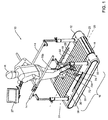
[0047] 概して図を参照すると、統合歩行リハビリテーション装置(例えば、歩行リハビリテーション装置16、歩行リハビリテーション装置316等)を含むトレッドミル10が、例示的実施形態に従い示される。トレッドミル10は、歩行ベルト18と、歩行ベルト18の回転を生じさせるために歩行ベルト18に動作可能に結合されたモータ102と、を含む。トレッドミル10は、モータ102から使用者係合構造(例えば、使用者係合構造70、使用者係合構造370)に原動力を伝達するトランスミッション(例えば、トランスミッション100、トランスミッション400、トランスミッション500等)をさらに含む。使用者係合構造70、370はリハビリティRに取外し自在に固定され、使用者係合構造70、370の運動がリハビリティRを所望の歩容で歩行させるようにし得る。従って、単一のモータ102が、歩行ベルト18の回転と、リハビリティRのリハビリテーション用歩行運動との両方を生じさせ得る。好ましくは、トランスミッション100、400、500は、リハビリティRの歩行運動を歩行ベルト18の歩行面19の速度に同期させて、歩行リハビリテーション装置16、316を含むトレッドミル10の動作が所望の歩容をシミュレートするようにする。単一のモータ102を使用することで、トレッドミル10の保守及び修理が容易になり、かつ、歩行ベルト18ではなく、むしろモータ102から動力を取るトランスミッション100、400、500を有することで、歩行ベルト18と使用者係合構造70、370との非同期化が低減され、従って歩行リハビリテーション装置16、316を介してリハビリティに伝達され得る原動力の大きさが増加する。
[0047] Referring generally to the figures, a
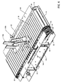
[0048] 示される例示的実施形態によれば、トランスミッション100、400、500は、同様に歩行ベルト18を駆動するリアシャフトアセンブリ60から動力を取り出す。トランスミッション100、400、500はリバースシャフトアセンブリ110、410によって回転方向を直し、リバースシャフトアセンブリ110、410がドライブシャフトアセンブリ120、420を回転させて、次にはそれがチェーン136、436を回転させる。チェーン136、436、536は、ドライブシャフトアセンブリ120、420、520及びアイドラシャフトアセンブリ130、430又はガイドアセンブリ530の周りの経路140、440、540を従動する。使用者係合構造70、370装置に結合された従動アセンブリ150、450、550が、チェーン136、436、536の経路140、440、540を従動し、それにより所望の歩容が生じる。
[0048] According to the exemplary embodiment shown, the
[0049] 簡単に図18〜図24、図25〜図37、及び図38〜図39を参照すると、トレッドミル10の他の例示的実施形態は、トランスミッション100、400、500、歩行リハビリテーション装置16、316、従動アセンブリ150、250、450、550、使用者係合構造70、370、又はこれら若しくは本開示に記載される他の構成要素の任意の組み合わせを含み得る。当業者が本開示を精査する際に認識及び理解するであるとおり、同様の機能及び/又は構造を有する構成要素は同様の命名法及び付番で記載される。
[0049] Referring briefly to FIGS. 18-24, 25-37, and 38-39, other exemplary embodiments of the
[0050] トレッドミル及び/又はその構成要素のさらなる詳細を考察する前に、本記載における「正面」、「背面」、「後部」、「上方」、「下方」、「内側」、「外側」、「右」、及び「左」に対する言及は、単に様々な要素を、図中でそれらが置かれている向きのとおり特定するために用いられるに過ぎないことに留意しなければならない。それらの様々な要素が様々な適用において異なる向きに置かれ得るとおり、これらの用語は、それが説明する要素を限定することを意図するものではない。 [0050] Before considering further details of the treadmill and / or its components, “front”, “back”, “rear”, “upper”, “lower”, “inner”, “outer” in this description. It should be noted that references to “right” and “left” are merely used to identify the various elements in the figure according to their orientation. These terms are not intended to limit the elements that they describe, as the various elements may be oriented differently in various applications.
[0051] さらに、本開示の目的上、用語「結合された」は、2つの部材の互いの直接的又は間接的な接合を意味することに留意しなければならない。かかる接合は、動かない性質のものであっても、又は、動かせる性質のものであってもよく、及び/又は、かかる接合は、2つの部材間に流体、電気、電気信号、若しくは、他の種類の信号又は通信が流れることを許容してもよい。かかる接合は、2つの部材又は2つの部材と任意のさらなる中間部材とが互いに一つの単体として一体形成されることによるか、若しくは、2つの部材又は2つの部材と任意のさらなる中間部材とが互いに取り付けられることで達成され得る。かかる接合は永久的な性質のものであってもよく、若しくは、取外し自在又は解除自在な性質のものであってもよい。 [0051] Furthermore, it should be noted that for the purposes of this disclosure, the term "coupled" refers to the direct or indirect joining of two members to each other. Such a bond may be non-movable or moveable and / or such a bond may be a fluid, electrical, electrical signal or other between the two members. You may allow a type of signal or communication to flow. Such joining may be due to two members or two members and any further intermediate member being integrally formed as one single piece, or two members or two members and any further intermediate member being connected to each other. It can be achieved by being attached. Such joining may be of a permanent nature, or may be of a removable or releasable nature.
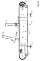
[0052] 図1及び図2を参照すると、基台12と、基台12に取り付けられた1以上の手すり14と、統合歩行リハビリテーション装置16と、その構成要素と、を概して含むトレッドミル10が、例示的実施形態に従い示される。歩行リハビリテーション装置16は、リハビリティの下肢が望ましい歩容パターンに従い動くよう誘導することにより、リハビリティR(例えば使用者等)がその歩容を回復又は改善するのを助けるように構成される。繰り返し使用することで、歩行リハビリテーション装置16は、以下でさらに詳細に考察するとおり、とりわけ、リハビリティが身体的に正しい歩き方を習得し直し、その筋機能を改善し、その筋記憶を改善し、及びその運動感覚の認知を改善するのを助け得る。
[0052] Referring to FIGS. 1 and 2, a
[0053] 基台12は、長手方向軸20に沿って実質的に長手方向に延在する歩行ベルト18(例えば、走行ベルト、スラット等)を含む。長手方向軸20は、概してトレッドミル10の前端部又はフロント端部22と後端部又はリア端部23との間に延在する;より具体的には、長手方向軸20は、概してフロントシャフト及びリアシャフトの中心線の間に延在し、これについては以下でさらに詳細に考察する。歩行ベルト18は、歩行面19として図示される、リハビリティRと接触してそれを支持する上側部分(例えば、走行面、上部領域等)を含む。歩行ベルト18はモータアセンブリ24によって長手方向に駆動され、1対のベアリングレール25によって案内される(モータアセンブリ24及びベアリングレール25を示す図4を参照)。モータアセンブリ24は、電気モータであることが示される駆動モータ102と、駆動モータ102の出力のギヤ減速(例えば、3:1〜8:1、5:1等)を提供するギヤボックス104と、を含むことが示される。別の実施形態によれば、トレッドミル10はギヤボックス104を含まないこともある。モータアセンブリ24によって歩行ベルト18が駆動される速度は、従来手段で(例えば、コントロールパネル26上のボタンを使用する、タッチセンサ式ディスプレイ27[例えば、タッチスクリーン等]を使用する、コンピュータを使用する等)調節され得る。
The
[0054] 基台12の右側及び左側に、リハビリティをトレッドミル10の構成要素又は動く部品から効果的に保護するため、1対のサイドパネル28、29(例えば、カバー、シュラウド等)が提供される。サイドパネル28、29の開口30、32により、歩行リハビリテーション装置16の構造が歩行ベルト18の上側に延在して、示される例示的実施形態ではリハビリティに動作可能に結合されることが可能になる。望ましくない物体が開口に入り込むことを防ぐ助けとなるよう、ブラシ又は他の同様の要素が開口30、32に配置され得ることに留意しなければならない。
[0054] A pair of
[0055] トレッドミル10は、例示的実施形態によれば概して基台12の真下に配置された1以上の支持部材をさらに含んで示される。支持部材は、歩行リハビリテーション装置16の動く構成要素、詳細には垂直可動部品用の間隙を提供する(例えば、図15及び図17を参照のこと)。示される例示的実施形態では、支持部材は、基台12を地面から離して持ち上げる4つの支持脚33を含む。基台12に可動式に結合される歩行リハビリテーション装置16の移動構成要素が、対応して地面から離して持ち上げられる。支持部材は、歩行リハビリテーション装置の動く部品を収容するのに好適な任意の構成を有し得ることに留意しなければならない。いくつかの例示的実施形態によれば、ピット設置が用いられ得る。一例示的実施形態において、ピット設置には、トレッドミル10が位置し得る空間の下にある地面にピット(例えば、開口、キャビティ、穴等)を形成することが関わる。トレッドミル10がピットのほぼ上方に配置され、歩行リハビリテーションシステムの動く構成要素がそのピット内に収容される。これらの構成のいくつかでは、これによりトレッドミル10の基台12及び/又は歩行面19を実質的に地面と面一に位置決めすることが可能になり、それにより理学療法士又は他の人がリハビリティをより容易に補助することが可能になる。別の例示的実施形態では、高床のプラットフォームがトレッドミル10の周りに組み立てられ得る。簡単に図34〜図37及び図38〜図39を参照すると、トランスミッションの他の実施形態(例えば、トランスミッション400、トランスミッション500)は、歩行面19を地面まで下げて位置決めすることを可能にし得る。
[0055] The
[0056] トレッドミル10の右側及び左側に沿って横方向に離間され、かつ、長手方向軸20とほぼ平行に延在する手すり14が示される。トレッドミル及びその様々な構成要素の左側及び右側は、トレッドミル10の歩行面19に立って前を向いている使用者の視点から定義されることに留意しなければならない。リハビリティは手すり14を支持のために(例えば、自身の体を直立に保つため、自身の体重を部分的に支持するため等)利用し得る。さらに、手すり14は、異なる身長、体格等の使用者に対応して調節可能であるように構成され得る。図3に示される例示的実施形態によれば、リハビリティの体重の少なくとも一部を支持するように構成されるか又はそれを人が支持することを可能にするように構成される体重支持システム34(例えば、機械的なカウンターウェイト、空気圧式装置、サーボ制御装置等)が、単独で、又は、手すり14及び/又は他の好適な構成を有する手すりとの組み合わせでトレッドミル10と共に利用され得る。図示されるとおり、体重支持システム34は、基台37から延在するブーム36を含む。プーリ又は滑車装置38を使用してリハビリティRの体重の一部又は全てが支持される。1以上の手動式又は電動式ウインチ39を使用して、ブーム36の位置及びリハビリティに加えられる力が制御され得る。これらの装置は取外し自在であってもよく、又は、トレッドミル10と一体化されてもよい。Hidlerに対する米国特許第7,883,450号(全体として参照により本明細書に組み入れられる)が、トレッドミル10と共に使用し得る別の体重支持システムを開示している。
[0056] A
[0057] 図4を参照すると、例示的実施形態によれば、基台12は、長手方向に延在する、左側部材42及び右側部材44として図示される対向する側部部材と、側部部材42、44の間に延在してそれらを構造的に連結する1以上の横方向部材又は横行部材46と、を含むフレーム40を含むことが示される。各側部部材42、44は内表面48と外表面49とを含む。左側部材42の内表面48は、右側部材44の内表面48の反対側にあり、それと対面している。他の例示的実施形態によれば、フレームは、トレッドミルに構造及び支持を提供するのに好適な実質的に任意の構成を有し得る。
[0057] Referring to FIG. 4, according to an exemplary embodiment, the
[0058] 例示的実施形態によれば、フロントシャフトアセンブリ50及びリアシャフトアセンブリ60がフレーム40に結合される。フロントシャフトアセンブリ50は、フロントシャフト54に相互連結された少なくとも1つ、好ましくは1対のフロントベルトプーリ52を含む。例えば、プーリ52は、好ましくはプーリ52をフロントシャフト54に固定するブッシング(例えば、テーパ穴キーレスブッシング)を使用してフロントシャフト54に取り付けられる。リアシャフトアセンブリ60は、リアシャフト64に相互連結された、及び好ましくはそれに取り付けられた少なくとも1つ、好ましくは1対のリアベルトプーリ62及び二次又はリアモータプーリ68を含む。フロントベルトプーリ52及びリアベルトプーリ62は、歩行ベルト18を支持し及びその動きを促進するように構成される。歩行ベルト18は、好ましくはそれぞれフロントシャフト54及びリアシャフト64に固定されたフロントベルトプーリ52及びリアベルトプーリ62の周りに配置される。モータアセンブリ24が一次又は駆動モータプーリ66を回転させ、その一次又は駆動モータプーリ66が第1ベルト又はモータベルト67、チェーン等を介してリアモータプーリ68を駆動する。リアモータプーリ68がリアシャフト64を回転させると、リアベルトプーリ62が回転し、歩行ベルト18及びフロントベルトプーリ52に同じ方向への回転が生じる。図示されるとおり、モータプーリ66、68は歯を有してモータベルト67を係合し、モータプーリに対するモータベルト67の滑りを防止する。同様にリアベルトプーリ62も歯を有して歩行ベルト18の歯付き部分を係合し、それらの間の滑りを防止することが示される。他の例示的実施形態によれば、モータはフロントシャフト及び駆動ベルトに動作可能に結合され得る。
[0058] According to an exemplary embodiment, the
[0059] 概して図1〜図4を参照すると、歩行リハビリテーション装置16は、第1又は左側使用者係合構造70aと、第2又は右側使用者係合構造70bと、を含む。第1及び第2使用者係合構造70a、70b(例えば、バインディング、ブーツ等)は、総称的に又はまとめて使用者係合構造70と称され得る。例示的実施形態によれば、使用者係合構造70は、以下にさらに詳細に記載される、トランスミッション100として図示される動力伝達装置(例えば、パワーテイクオフ装置、ドライブライン、動力学的経路等)を介してリアシャフトアセンブリ60及びモータアセンブリ24に結合され、より好ましくはそれと動作可能に相互連結される。使用者係合構造70は、リハビリティの下肢の望ましい位置に対して取外し自在に固定され、それによって運動がトランスミッション100からリハビリティに伝達され、リハビリティを望ましい歩容で歩行させるように構成される。使用者係合構造70は、トランスミッション100に結合され、好ましくはそれと相互連結される。簡単に図1〜図3を参照すると、歩行リハビリテーション装置16の左側使用者係合構造70a及び右側使用者係合構造70bの各々は、ストラップ72、74として図示される1以上の支持又は結合機構を含み、これがリハビリティのそれぞれ左脚又は左足及び右脚又は右足に対して使用者係合構造70を解除可能及び調節可能に固定し得る。このようにして、トランスミッション100からの駆動力が歩行リハビリテーション装置16からリハビリティに伝達され得る。他の実施形態によれば、リハビリティの足を足指又は足底弓近傍で使用者係合構造70に拘束するさらなる結合機構を使用してもよい。
[0059] Referring generally to FIGS. 1-4, the
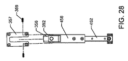
[0060] 図25及び図33を参照すると、左側使用者係合構造370a及び右側使用者係合構造370bとして図示される別の使用者係合構造370が、例示的実施形態に従い示される。この使用者係合構造370は、脛又はふくらはぎの周りで使用者を係合するのでなく、代わりにストラップ(図示せず)を使用してリハビリティの足又は靴にしっかりと縛り付けられる。脛及びふくらはぎの周りよりも、むしろリハビリティの足に縛り付けることで、足首の回転及び足の屈曲が可能になるため、リハビリティがより自然な歩容で訓練される。好ましくは、リハビリティの足首が横方向部材454と軸方向に整列し、従って足の屈曲が取付け具456及び横方向部材454の回転に対応するようにされる。全てのリハビリティが同じサイズの足であるとは限らず、リハビリティの足首を横方向部材454と整列させるためには、異なるサイズの使用者係合構造370を使用しなければならないか、又は、使用者係合構造370が、異なるサイズのリハビリティの足を受け入れるための調節システムを含まなければならない。示される例示的実施形態によれば、使用者係合構造370は調節可能な踵部分371を含む。調節可能な踵部分371は、外側及び内側スロット376と、使用者係合部分370の後部に結合された締付け部分378と、を含むことが示される。締付け部分378はスロット377を含み、ストラップ(図示せず)の第1端部を固定するために使用され得る。例えば、好ましくはその表面に配置された面ファスナ締結システムを有するストラップの第1端部が、ストラップの第2端部をスロット377に通過させることができなくなるまでスロット377に通して送り込まれる。次にストラップの第1端部が踵部分371の外側及び内側スロット376に通して送り込まれ、次にストラップの第1端部がストラップの第2端部に近接してストラップに結合される。使用時、使用者係合構造370に対するリハビリティの足の位置は、踵部分371に通されるストラップとリハビリティの足の甲に渡され、かつ、スロット373、375に通されるストラップ(図示せず)との相対的な締付け(例えば、緊縮性(taughtness)等)を選択的に調節することにより調節され得る。従って、使用者係合構造370はフリーサイズのブーツであってもよい。
[0060] Referring to FIGS. 25 and 33, another
[0061] 図4〜図17を参照すると、歩行リハビリテーション装置16、及びその構成要素が、例示的実施形態に従い示される。歩行リハビリテーション装置16の特定の構成要素がトレッドミル10の左側又は右側に示されるが、様々な他の実施形態によれば、それらの構成要素の一部又は全てを反対側に(例えば、左を右に又は右を左に等)入れ替えてもよく、構成要素の全てをトレッドミル10の片側(例えば、左側又は右側)に移動させてもよく、又は、構成要素をフロントシャフトアセンブリ50によって駆動してもよい。
[0061] Referring to FIGS. 4-17, the
[0062] 示される例示的実施形態によれば、かつ、図5及び図13で最も良く分かるとおり、歩行リハビリテーション装置16はトランスミッション100と従動アセンブリ150とを含み、ここで従動アセンブリ150は使用者係合装置70に結合され、トランスミッション100はモータアセンブリ24から動力又は原動力を受け取り、その原動力を伝達及び/又は変換して従動アセンブリ150の運動を生じさせ、それにより使用者係合装置70の運動が生じ、ひいてはリハビリティの運動が生じる。トランスミッション100は、リアシャフト64に相互連結され、好ましくはそれに取り付けられるパワーテイクオフプーリ69を含むことが示される。トランスミッション100は、パワーテイクオフプーリ69から原動力を受け取って原動力の回転方向を逆転させ又は修正するように構成されたリバースシャフトアセンブリ110と、リバースシャフトアセンブリ110から原動力を受け取ってチェーン136を駆動するように構成されたドライブシャフトアセンブリ120と、チェーン136の経路140を支持し及びそれを少なくとも部分的に画定するように構成されたアイドラシャフトアセンブリ130と、をさらに含む。従動アセンブリ150はチェーン136を可動式に結合し、その経路を従動する。
[0062] According to the exemplary embodiment shown, and as best seen in FIGS. 5 and 13, the
[0063] リバースシャフトアセンブリは、リバースシャフト114として図示されるシャフトと相互連結され、好ましくはそれに取り付けられるプーリ112及びギヤ113を含む。プーリ112は、第2ベルト又はテイクオフベルト116を介してパワーテイクオフプーリ69と相互連結される。一実施形態によれば、パワーテイクオフプーリ69及びプーリ112は歯を有してテイクオフベルト116の歯付きの内側部分を係合し、それによりそれらの間の滑りを防止する。テンショナ118がテイクオフベルト116に力を加えることでテイクオフベルト116を案内し、テイクオフベルト116の任意のスラックを取り得る。図17に図示されるとおり、テンショナ118はフレーム40の右側部材44に結合され得る。フレーム40における1以上のスロット119によりテンショナ118の位置を調節することができ、それにより組立公差に対応し、テイクオフベルト116の伸びが補償されるよう調節することが可能になる。別の実施形態によれば、テンショナ118は、テイクオフベルト116の任意のさらなるスラック又は張力に自動的に応答する弾性機構(例えば、ばね)を含み得る。他の実施形態によれば、パワーテイクオフプーリ69はモータアセンブリ24の出力シャフトに、駆動モータプーリ66又は駆動モータプーリ66と反対側のモータ102に隣接して結合されてもよく、又は、パワーテイクオフプーリ69はフロントシャフトアセンブリ50のフロントシャフト54に結合されてもよい。かかる実施形態では、トランスミッション100は、原動力の回転方向を修正するリバースシャフトアセンブリ110を含まないこともあり得る。
[0063] The reverse shaft assembly includes a
[0064] 図34及び図36を参照すると、テンショナ418が例示的実施形態に従い示される。テンショナ418は、フレーム40の右側部材44に結合され得る。フレーム40の1以上のスロット419により、テンショナ418がテイクオフベルト116の下部分を押し上げるようにテンショナ418の位置を調節することができ、それにより組立公差に対応し、テイクオフベルト116の伸びが補償されるよう調節することが可能になる。調整ねじ417がフレーム40の下部分又はフレーム40に結合されたナットを螺通し、ねじの端部がテンショナ418を押し付けるようにし得る。従って、ねじ417を前進させると、テイクオフベルト116にかかる張力の増加が生じ、ねじ417を後退させると、テイクオフベルト116にかかる張力の減少が生じる。
[0064] Referring to FIGS. 34 and 36, a
[0065] 簡単に図18〜図20を参照すると、トランスミッション100は、従動アセンブリ150、250をモータアセンブリ24に選択的に結合したり、切り離したりすることを可能にするクラッチ180を含み得る。クラッチ180が第1の(例えば、係合した、結合した、クラッチがつながれた等の)状態にあるとき、モータアセンブリ24から使用者係合構造70に運動が伝達され、クラッチ180が第2の(例えば、外された、切り離された、クラッチが切られた等の)状態にあるとき、トランスミッション100を介したモータアセンブリ24から使用者係合構造70への運動の伝達はない。一実施形態によれば、クラッチ180は、歩行リハビリテーション装置16の運動を歩行ベルト18の運動と切り離すことを可能にする。クラッチ180を使用して歩行リハビリテーション装置16の運動を歩行ベルト18の運動から切り離すことにより、歩行リハビリテーション装置16を伴わないトレッドミル10の使用が促進される。クラッチ180は可変クラッチであってもよく、これは、進歩したリハビリティにさらに大きい割合の推進力を提供することを可能にし又はそれを要求するように調節することができる。クラッチ180はまた、以下に記載する緊急停止システムと併せて使用されてもよい。
[0065] Referring briefly to FIGS. 18-20, the
[0066] 示される実施形態によれば、クラッチ180は、プーリ112とリバースシャフト114との間に位置する磁気クラッチである。例えば、クラッチ180のロータがプーリ112に結合されてもよく、クラッチ180のアーマチャがリバースシャフト114に結合されてもよい。従って、クラッチ180が通電されるとクラッチ180が係合し、プーリ112からリバースシャフト114にトルクが伝達され得る。クラッチ180は、コントロールパネル26、27上の使用者入力装置(例えば、スイッチ、ボタン、ノブ、レバー、タッチスクリーンインタフェース等)によって制御され得る。他の実施形態によれば、クラッチ180は、コントロールパネル26、27に結合された処理電子機器によって制御され得る。様々な実施形態によれば、クラッチ180は機械クラッチ若しくは油圧クラッチであってもよく、又は、別の位置、例えばリアシャフト64とパワーテイクオフプーリ69との間に位置してもよい。
According to the illustrated embodiment, the clutch 180 is a magnetic clutch located between the
[0067] 図4〜図17に戻ると、上述のとおり、ドライブシャフトアセンブリ120がリバースシャフトアセンブリ110から原動力を受け取るように構成される。ドライブシャフトアセンブリ120は、少なくとも1つ、好ましくは左側リアスプロケット122a及び右側リアスプロケット122bとして図示される1対の第1スプロケット又はリアスプロケット122と、ドライブシャフト124として図示されるシャフトに相互連結され、好ましくはそれに取り付けられたギヤ123と、を含む。
Returning to FIGS. 4-17, the
[0068] アイドラシャフトアセンブリ130は、チェーン136の経路140を支持及び画定し、かつ、アイドラシャフト134として図示されるシャフトに相互連結され、好ましくはそれに取り付けられた、左側前スプロケット132a及び右側前スプロケット132bとして図示される1対の第2又は前スプロケット132を含む。左側チェーン136a及び右側チェーン136bとして図示される1対のベルト又はチェーン136がリアスプロケット122と前スプロケット132との間に延在し、かつ、それらを動作可能に結合する。左側ピン138a及び右側ピン138bとして図示されるピン138が、チェーン136の各々に結合される。
[0068] The
[0069] 示される例示的実施形態によれば、リアシャフト64は、それがモータアセンブリ24によって駆動されるときに歩行ベルト18の方向に回転し、従ってリアシャフト64に結合されたパワーテイクオフプーリ69もまた同じ方向に回転する。動力がプーリ112及びテイクオフベルト116を介してパワーテイクオフプーリ69からリバースシャフト114に伝達される。リバースシャフトは歩行ベルト18と同じ方向に回転している。動力がリバースシャフト114を経てギヤ113に伝達され、ギヤ113はドライブシャフトアセンブリ120のギヤ123に係合される。ギヤ113、123の係合により、ドライブシャフトアセンブリ120にリバースシャフトアセンブリ110と逆の(すなわち、リアシャフトアセンブリ60及び歩行ベルト18と同じ方向の)回転が生じる。次にリアスプロケット122がチェーン136を、左側経路140a及び右側経路140bとして図示される、歩行ベルト18と同じ方向に進む又は回転する循環的経路140に従動させる。従って、ピン138はこの循環的経路140を従動する。一部の実施形態によれば、循環的経路は卵形、楕円形、又は涙滴形を有し得る。示される例示的実施形態によれば、循環的経路はレーストラック形を有する。別の実施形態によれば、トレッドミルはリバースシャフトアセンブリ110を含まず、代わりにドライブシャフト124に取り付けられたプーリ112を有し、パワーテイクオフプーリ69とプーリ112との間でテイクオフベルト116が完全にねじれていることにより、リアシャフトアセンブリ60と同じ方向へのドライブシャフトアセンブリ120の回転が生じる。
[0069] According to the exemplary embodiment shown, the
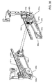
[0070] 図30〜図34を参照すると、例示的実施形態に従いトランスミッション400が示される。リアシャフト64がモータアセンブリ24によって駆動されると、リアシャフト64は、歩行ベルト18の方向に回転し、従ってリアシャフト64に結合されたパワーテイクオフプーリ69もまた同じ方向に回転する。動力がプーリ412及びテイクオフベルト116を介してパワーテイクオフプーリ69からリバースシャフト414に伝達される。リバースシャフトは歩行ベルト18と同じ方向に回転している。特に、リバースシャフトアセンブリ410及びドライブシャフトアセンブリ420が、トランスミッション100に対して入れ替わった位置を有する。リバースシャフトアセンブリ410がドライブシャフトアセンブリの後ろにあるため、テイクオフプーリ69、テイクオフベルト116、及びプーリ412は、ガイドアセンブリ460を妨げることなしにリアスプロケット422及びチェーン436の外部で動き得る。チェーン436及びガイドアセンブリ460が内部で動くと、ガイドアセンブリ460と使用者係合構造370との間の横方向距離が減少する。この横方向距離の減少によって一層コンパクトな歩行リハビリテーション装置316が可能となり(従ってより多くの余裕が療法士に提供される)、横方向部材454の長さが減少する。この横方向部材454の長さの減少により、横方向部材454にかかる曲げ応力が小さくなる。
[0070] Referring to FIGS. 30-34, a transmission 400 is shown in accordance with an exemplary embodiment. When the
[0071] 動力はリバースシャフト414を経てギヤ413に伝達され、このギヤ413は、ドライブシャフトアセンブリ420のギヤ423に係合される。ギヤ413、423の係合により、ドライブシャフトアセンブリ420にリバースシャフトアセンブリ410と逆の、すなわちリアシャフトアセンブリ60及び歩行ベルト18と逆の方向への回転が生じる。次にリアスプロケット422がチェーン436を、歩行ベルト18と同じ方向に進む又は回転する循環的経路に従動させる。一部の実施形態によれば、循環的経路は、卵形、楕円形又は涙滴形を有し得る。示される例示的実施形態によれば、循環的経路はレーストラック形を有する。
The power is transmitted to the
[0072] トランスミッション400は、従動アセンブリ450をモータアセンブリ24と選択的に結合したり切り離したりすることを可能にするクラッチ480を含み得る。クラッチ480は、クラッチ180を参照して上記に記載したとおり動作し得る。図示されるとおり、クラッチ480はリバースシャフト414とギヤ413とを動作可能に結合したり、切り離したりする。ブラケット431がフレーム40の横行部材46に結合されてもよく、クラッチ480の重量を支えるよう助け得る。例えば、簡潔に図34を参照すると、ブラケット431は、リバースシャフト414に結合されているベアリング411を支持することが示される。
[0072] The transmission 400 may include a clutch 480 that allows the driven
[0073] 図4〜図17に戻ると、及び図15及び図17で最も良く分かるとおり、ピン138の循環的経路140は、歩行ベルト18の歩行面19と同じ方向に進む第1部分又は下部分141を含み、かつ、歩行面19の方向と逆に進む第3部分又は上部分143を含む。経路140の第2部分又はリア部分142は下部分141から上部分143へと移行し、上向き構成要素を含む。経路140の第4部分又はフロント部分144は、上部分143から下部分141へと移行し、下向き構成要素を含む。トランスミッション100は、好ましくは、ピン138が経路140の下部分141を通るときのピン138の後ろ向き速度が歩行ベルト18の歩行面19の後ろ向き速度と等しくなるように構成される(例えば、そのようにプーリ比及びギヤ比が選択される)。様々な実施形態によれば、例えば、上部分143に沿って、経路140の形状を精緻化するためのさらなるアイドラスプロケットが使用されてもよい。他の実施形態によれば、リアスプロケット122及び前スプロケット132の少なくとも1つが実質的に非円形の形状(例えば、長円形、卵形、楕円形、多角形、ルーロー多角形等)を有することで、リハビリティに付与される運動が精緻化され得る。
[0073] Returning to FIGS. 4-17, and as best seen in FIGS. 15 and 17, the
[0074] 例示的実施形態によれば、歩行リハビリテーション装置16は少なくとも1つの従動アセンブリ150をさらに含むことが示される。第1又は左側従動アセンブリ150a及び第2又は右側従動アセンブリ150bとして図示される従動アセンブリは、ピン138と使用者係合構造70とを相互連結し、それらの間に原動力を伝達する。従って、ピン138の循環的運動が使用者係合構造70に伝達され、次にはそれが、リハビリティに歩容(例えば、所望の歩容、歩行歩容等)をシミュレートさせるように運動を付与する。左側ピン138a及び右側ピン138bは、好ましくはチェーン136a、136bの各々に互いに180度位相がずれて結合され、従ってそれに相互連結される使用者係合構造70が二足歩行の歩容を生じるように同期する形で動く。
[0074] According to an exemplary embodiment, the
[0075] 示される実施形態によれば、リアスプロケット122は前スプロケット132より大きく、これにより経路140が自然の歩容をより良く近似する。他の実施形態によれば、フロントスプロケット132及びリアスプロケット122は任意のサイズ又は相対的サイズであってよく、1以上のさらなるスプロケットがチェーン136をより複雑な経路に案内し、例えばそれにより異なる歩容をシミュレートするか、又は、自然の歩容をより正確にシミュレートしてもよい。従動アセンブリはさらに、使用者係合構造70をピン138から離間させることを可能にし、例えばそれによりトランスミッション100が歩行面19の下側及び/又は横方向外側に位置してもよく、一方で使用者係合構造70が歩行面19の上側に位置し、実質的に自然の歩容を提供するように横方向に離間される。
[0075] According to the embodiment shown, the rear sprocket 122 is larger than the front sprocket 132, so that the
[0076] 従動アセンブリ150は、ピン138に回転自在に結合された従動体151と、使用者係合構造70に取外し自在に結合されたジョイント又は取付け具156と、従動体151と取付け具156とを相互連結する1以上の部材と、を含むことが示される。従動体151をピン138に回転自在に結合することにより、ピン138及びチェーン136が循環的経路140を従動するに従い向きが変わっても、従動体151はトレッドミル10に対して直立した向きのまま留まることが可能である。示される実施形態によれば、ピン138はチェーン136に固定され、ピン138は従動体151に受け入れられる。別の実施形態によれば、ピンは従動体151に固定され、ピンはチェーン136に受け入れられる。別の実施形態によれば、ピン138は、チェーン136及び従動体151の両方に回転自在に結合される。
[0076] The follower assembly 150 includes a
[0077] 図5で最も良く分かるとおり、一実施形態によれば、1以上の部材は単一のL字型部材であってもよい。図示されるとおり、1以上の部材は、従動体151に結合される第1部材又は垂直部材152(例えば、ロッド、ビーム、シャフト等)と、ジョイント153で垂直部材152に結合される第2部材又は横方向部材154と、を含む。横方向部材154は、ジョイント153に結合される第1端部分と、第1端部分の遠位にある第2端部分と、を含む。第2端部分は、ブロック158として図示される取付け具156の第1部分に回転自在に結合される。ブロック158は、ハウジング157として図示される取付け具156の第2部分に解除可能に結合され、ハウジング157は使用者係合構造70に固定されている。示される実施形態によれば、ハウジング157は、ハウジング157及びブロック158の整列したそれぞれの穴155及び155’を貫通する1以上のピン159を使用して、ブロック158に解除可能に固定され得る。使用者係合構造70を従動アセンブリ150に解除可能に結合することにより、歩行リハビリテーション装置16で異なるサイズ及び種類の使用者係合構造、例えば、より硬い又はより柔らかい底板を有する使用者係合構造、裸足歩行を可能にする底板を有しない使用者係合構造等を使用することが可能となる。
[0077] As best seen in FIG. 5, according to one embodiment, the one or more members may be a single L-shaped member. As shown, the one or more members include a first member or vertical member 152 (eg, rod, beam, shaft, etc.) coupled to the
[0078] 示される実施形態によれば、ジョイント153は垂直部材152の上へとそれに沿って摺動する。一実施形態によれば、ジョイント153及び垂直部材152は滑り嵌めの関係を有し、前後及び垂直荷重が垂直部材152から使用者係合構造70へとジョイント153を介して伝達されることが可能になる。ジョイント・オーバー・ポスト(joint-over-post)構成により、療法士は使用者係合構造70、取付け具156、横方向部材154、及びジョイント153をリハビリティに連結し、次に垂直部材152の上にあるジョイント153を下げることによって、かかるアセンブリをトランスミッション100に容易に結合することが可能になる。
[0078] According to the illustrated embodiment, the joint 153 slides onto and along the
[0079] 図示されるとおり、ジョイント153は垂直部材152に固定又は締結されない。一実施形態によれば、所定の力の戻り止めがジョイント153と垂直部材152とを結合してもよい。戻り止めは、ジョイント153が垂直部材152に適切に結合されているという正のフィードバックを提供し得る。さらに、小さい戻り止めの力は、ジョイント153が垂直部材152から偶発的に切り離されることは抑止し得るが、しかし十分な力があればジョイント153を垂直部材152から切り離すことは可能にし得る。例えば、ジョイント・オーバー・ポスト構成及び/又は戻り止めは、ジョイント153の使用者係合構造70側とジョイント153のトランスミッション100側との間に十分な荷重差が生じた場合、例えばリハビリティがつまずいた場合に、リハビリティが垂直部材152から外れることを可能にし得る。別の実施形態によれば、緊急時、リハビリティは単純に体重支持システム34によって持ち上げられてトレッドミル10から離され、ここではジョイント153が垂直部材152と分離される。クラッチ180を有する実施形態では、緊急停止システムがモータアセンブリ24を停止させてクラッチ180を切り離し、ここではジョイント153は必要に応じて垂直部材152と分離される。
[0079] As shown, the joint 153 is not fixed or fastened to the
[0080] 簡単に図20〜図22を参照すると、従動アセンブリ250として図示される従動アセンブリの別の実施形態が、別の例示的実施形態に従い示される。図示されるとおり、従動アセンブリ250は、従動体151を介してチェーン136に結合される第1部材又は垂直部材252を含む。ジョイント253が垂直部材252を、使用者係合構造70に結合される第2部材又は横方向部材254に結合する。ジョイント253は、垂直部材252に摺動自在に結合される第1部分256と、横方向部材254に選択的に結合される第2部分257と、を含む。第1部分256は、垂直部材252の外側に沿って下方に延在するフランジ255を含むことが示される。外側に沿って延在することにより、上部シャトル161を妨げることなく第1部分256を垂直部材252に固定するための1以上の締結具を貫通させ得る領域が提供される。
[0080] Referring briefly to FIGS. 20-22, another embodiment of a driven assembly, illustrated as a driven assembly 250, is shown in accordance with another exemplary embodiment. As shown, the follower assembly 250 includes a first or
[0081] 第1部分256は、第2部分の少なくとも一部をそこに受け入れるように構成されたスロット258を含むことが示され、かつ、、示される実施形態によれば、第1部分256及び第2部分257を貫通してピン259が延在することにより、ジョイント253の2つの部分が連結される。かかるアセンブリにより、療法士は使用者係合構造70、取付け具156、横方向部材254、及びジョイント253の第2部分257をリハビリティに連結し、次にジョイント253の第2部分257をジョイント253の第1部分256のスロット258に置くことによって、かかるアセンブリをトランスミッション100に容易に結合することが可能になる。
[0081] The
[0082] 様々な実施形態によれば、ピン259はアクスル又はヒンジとして働き、第2部分257がその周りに回転することを可能にし得る。かかる回転により、使用者又は療法士はハウジング157をブロック158と切り離して横方向部材154を上方外側に回転させ、歩行ベルト18の上側の空間をあけることが可能になり得る。かかる構成により、所望される場合に療法士がリハビリティを介助付きの歩行から自力歩行へと速やかに移行させ、及び再び戻すことが可能になる。
[0082] According to various embodiments, the
[0083] 別の実施形態によれば、ジョイント253の第1部分256及び第2部分257は、戻り止め、例えば、第1部分256又は第2部分257の一方にある弾性的に付勢された(例えば、ばね荷重式等の)部材(例えば、ロッド、ボール等)によって、それが第1部分256又は第2部分257の他方の陥凹部に係合して結合されてもよい。上記に記載したとおり、戻り止めは、第1部分256と第2部分257との結合に関する正のフィードバックを提供することができ、第1部分256又は第2部分257を速やかに結合したり切り離したりすることを促進し得るとともに、例えばリハビリティがつまずいた場合に、ジョイント253の使用者係合構造70側とジョイント253のトランスミッション100側との間の十分な荷重差に応答して第1部分256が第2部分257から切り離されることを可能にし得る。
[0083] According to another embodiment, the
[0084] 図25〜図29及び図33〜図34を参照すると、従動アセンブリ450として図示される従動アセンブリの別の実施形態が、別の例示的実施形態に従い示される。図示されるとおり、従動アセンブリ450は、従動体451によってチェーン436に結合される第1部材又は垂直部材452を含む。ジョイント453が垂直部材452を、使用者係合構造370に結合される第2部材又は横方向部材454に結合する。ジョイント453は、垂直部材452に摺動自在に結合される第1部分456と、横方向部材454に選択的に結合される第2部分457と、を含む。第1部分456は、垂直部材452の外側に沿って下方に延在するフランジ455を含むことが示される。外側に沿って延在することにより、シャトル161を妨げることなく第1部分456を垂直部材452に固定するための1以上の締結具を貫通させ得る領域が提供される。
[0084] Referring to FIGS. 25-29 and 33-34, another embodiment of a driven assembly, illustrated as a driven
[0085] 第1部分456は、第2部分457の少なくとも一部をそこに受け入れるように構成されたスロット458を含むことが示され、かつ、第1部分456及び第2部分457を貫通してピン(図示せず)が延在することにより、ジョイント453の2つの部分が連結される。かかるアセンブリにより、療法士は使用者係合構造370、取付け具456、横方向部材454、及びジョイント453の第2部分457をリハビリティに連結し、次にジョイント453の第2部分457をジョイント453の第1部分456のスロット458に置くことによって、アセンブリをトランスミッション400に容易に結合することが可能になる。
[0085] The
[0086] 示される例示的実施形態によれば、横方向部材454はジョイント453の第2部分457に対して軸方向又は横方向に調節することができる。図示されるとおり、横方向部材454が、横方向部材454の長さの一部分に沿って軸方向に離間された、穴390として図示される複数の位置を含んでもよく、かつ、第2部分457が、第2部分457の側壁を貫通して延在する穴391を含んでもよい。ピン397として図示される締結具が第2部分457の穴391を通って延在し、横方向部材454の選択的に位置合わせされた穴390に入る。従って、歩行ベルト18に対する使用者係合構造370の相対的な横方向位置を選択的に調節することができ、様々なサイズ及び必要性のリハビリティに対応し得る。例えば、使用者係合構造370と第2部分457(従って従動体451)との間の相対的な横方向間隔を調節し得る。
[0086] According to the exemplary embodiment shown, the
[0087] 図示されるとおり、横方向部材454は、ジョイント453に結合される第1端部分と、第1端部分の遠位の、ブロック358として図示されるジョイント又は取付け具356の第1部分に回転自在に結合される第2端部分と、を含む。ブロック358は、ハウジング357として図示される取付け具356の第2部分に解除可能に結合され、ハウジング357は使用者係合構造370に固定されている。ハウジング357はチャネル393を少なくとも部分的に規定する。ハウジング357はチャネル393を完全に規定してもよく、又は図示されるとおり、ハウジング357と使用者係合構造370とが協働してチャネル393を規定してもよい。チャネル393は、実質的に垂直に延在し、かつ、ブロック358のフランジ392を受け入れることが示される。従って、リハビリティは使用者係合構造370を装着し、次に使用者係合構造370をブロック358に結合する(例えば、それを踏み込む等)。示される実施形態によれば、ハウジング357は、ハウジング357及びブロック358にある整列したそれぞれの穴355及び355’を通る1以上の締結具又はピン359を使用して、ブロック358に解除可能に固定され得る。使用者係合構造370を従動アセンブリ450と解除可能に結合することにより、歩行リハビリテーション装置316で異なるサイズ及び種類の使用者係合構造、例えば、より硬い又はより柔らかい底板を有する使用者係合構造、裸足歩行を可能にする底板を有しない使用者係合構造等を使用することが可能となる。
[0087] As shown, the
[0088] 戻り止め機構を使用してハウジング357がブロック358に結合されてもよい。一例示的実施形態によれば、ピン359がハウジング357に弾性的に結合されてもよい。別の例示的実施形態によれば、ピン359は、穴355’とばね荷重転がり軸受とが整列したとき穴355’を係合するように構成された1以上のばね荷重転がり軸受であってもよい。かかる戻り止め機構は、リハビリティ及び/又は療法士に、ハウジング357がブロック358に適切に着座しているという正のフィードバックを提供し得るとともに、例えば緊急の場合に、リハビリティを歩行リハビリテーション装置316から素早く切り離すことを可能にし得る。通常の使用時はリハビリティの体重がハウジング357に対して下向きに作用し、ハウジング357がブロック358を押し付けているため、戻り止め機構は偶発的な又は不注意による切り離しを防ぐ程度に強力であれば十分である。
[0088] The
[0089] ブロック358は横方向部材454に回転自在に結合され、かつ、軸方向に固定され得る。図示されるとおり、ブロック358は保持アセンブリ350によって横方向部材454に結合される。ブロック358の外側でクリップ352が横方向部材454のスロット又は溝351を係合する。ブロック358の内側でワッシャ又はプラグ353が横方向部材454に嵌められる。一実施形態によれば、プラグ353は横方向部材454と摩擦で結合され得るか(例えば、圧入等)、又は螺合式に結合され得る。示される実施形態によれば、ピン354がプラグ353の内側で横方向部材454の穴394を通って延在する。クリップ352、ブロック358、プラグ353、及びピン354のアセンブリは、好ましくは十分に締まっているためブロック358が横方向部材454に対して軸方向に動くことを防止し、一方でブロック358が横方向部材454に対して回転する動きは可能にする。
[0089] The
[0090] 図5に戻ると、使用者係合構造70を従動アセンブリ150に解除可能に結合することにより、使用者係合構造をトレッドミル10から取り外して、機械的補助を必要としない又は片方の脚に対する歩容補助だけが必要であり得る健常な使用者又はリハビリティがトレッドミル10を使用できるようすることがさらに可能となる。使用者係合構造70のないトレッドミル10の使用をさらに促進するため、歩行ベルト18の上に延在する位置から歩行ベルト18の上に延在しない位置(例えば、実質的に垂直な位置又は実質的に前後の位置)へと横方向部材154を動かすことができるようにジョイント153が回転してもよい。
[0090] Returning to FIG. 5, by releasably coupling the
[0091] 一実施形態によれば、従動アセンブリ150は可変支持システムを含み得る。例えば、垂直部材152が従動体151に弾性的に又はばね式に結合され得る。別の例によれば、横方向部材154がブロック158に弾性的に又はばね式に結合され得る。可変支持システムにより、ピン138に対する使用者係合構造70の可動範囲を制限することが可能になる。従って、ピン138が経路140のリア部分142を従動するとき、可変支持システムはピン138の最初の上向きの運動の一部を吸収し(例えば、引き受ける、補償する等);従って、使用者係合構造70は歩行ベルト18の歩行面19からより緩慢に(それ程早急及び急激でなく)持ち上がり得る。同様に、ピン138が経路140のフロント部分144を従動するとき、可変支持システムはピン138の最後の下向きの運動の一部を吸収し(例えば、ピン138が後ろ方向に進み始める点とピン138の進みが下向きでなくなる点との間、経路140の最も前方にある点と経路140の最も下にある点との間、第2スプロケット132の最も前方にある点に近接した点と第2スプロケット132の下部に近接した点との間等);従って、使用者係合構造70が後ろ向きに運動し始めるのとほぼ同時に使用者係合構造70が歩行面19と接触することが可能になる。様々な実施形態によれば、従動アセンブリ150は、より細かい又は自然な歩行運動を提供するため横方向駆動システム及び/又は足首関節接合システムを含み得る。例示的な横方向駆動システム及び足首関節接合装置が、全体として参照により本明細書に援用されるBayerlein et al.に対する米国特許出願第12/757,725号明細書に図示及び説明される。
[0091] According to one embodiment, the follower assembly 150 may include a variable support system. For example, the
[0092] 別の実施形態によれば、従動アセンブリは、垂直部材152及び歩行面19に対する使用者係合構造70の回転角を制限又は抑制する機構を含み得る。例えば、横方向部材154がカム部分を有してもよく、かつ、取付け具156又はジョイント153が、カム部分に隣接してその回転を制限するための1以上のプレートを含んでもよい。例えば、カム部分がローブを含んでもよく、ローブが所定の角度又は回転でプレートの1つと接触して、所定の角度を超えるそれ以上の回転を防止する。使用者係合構造70の可能な回転(例えば、底屈、背屈等)を制限することにより、リハビリティが前に踏み出すときのリハビリティによる過伸展が防止され、又はリハビリティが歩行ベルト18につま先を先につくことが防止され得る。
[0092] According to another embodiment, the driven assembly may include a mechanism that limits or constrains the rotation angle of the
[0093] 図25〜図29を参照すると、従動アセンブリ450が、少なくとも部分的に横方向部材454を通って延在するピン354を含む保持アセンブリ350を含み得る。ピン354のうち横方向部材454から延在する一部分は、ブロック358に規定されるキャビティ395に配置される。キャビティ395は、少なくとも部分的には、横方向部材454の長手方向軸に近接する点(この点は、例えばピン354の厚さを補償するため、軸からずれていてもよい)から半径方向に延在する表面396、396’によって規定される。横方向部材454の第1方向(例えば、時計回り、反時計回り等)への回転は、ピン354がこれらの表面のうち第1表面396に接触すると止まる。横方向部材454の第2方向(例えば、反時計回り、時計回り等)への回転は、ピン454がこれらの表面のうち第2表面396’に接触すると止まる。従って、協働する表面396、396’の間の角度を選択することにより、使用者係合構造370の可能な回転を所望の範囲に制限し得る。
[0093] Referring to FIGS. 25-29, the
[0094] 歩行リハビリテーション装置16は、例示的実施形態によれば、従動体151及び垂直部材152を実質的に直立した向きに維持するためのガイドアセンブリ160をさらに含むことが示される。すなわち、ガイドアセンブリ160が従動アセンブリ150の可動域又は自由度を制限する。ガイドアセンブリ160は、第1シャトル又は上部シャトル161(例えば、スライダ、ガイド等)を含むことが示される。上部シャトル161は垂直部材152に摺動自在に結合され、従って垂直部材152は上部シャトル161に対して実質的に垂直に摺動し又は並進し得る。上部シャトル161はまた、第1レール又は上部レール162(例えば、レール等)にも摺動自在に結合され、従って上部シャトル161は上部レール162に沿って前後方向に実質的に水平に摺動又は並進し得る。上部レール162は、フレーム40のそれぞれの側部部材42、44の外表面49にブラケット163によって相互連結されることが示される。ブラケット163は横方向に延在する上部フランジ164を含んでもよく、これは上部シャトル161及び上部レール162をごみ屑から保護する。垂直部材152に沿って従動体151以外の点を拘束することにより、ガイドアセンブリ160は垂直部材を実質的に直立した向きに維持することができ、それにより歩行リハビリテーション装置16からリハビリティへの垂直の力の伝達が促進される。
[0094] The
[0095] ガイドアセンブリ160は、第2シャトル又は下部シャトル165(例えば、スライダ、ガイド等)をさらに含むことが示される。下部シャトル165は垂直部材152に摺動自在に結合され、従って垂直部材152は下部シャトル165に対して実質的に垂直に摺動又は並進し得る。下部シャトル165はまた、第2レール又は下部レール166(例えば、レール等)にも摺動自在に結合され、従って下部シャトル165は下部レール166に沿って前後に実質的に水平に摺動又は並進し得る。下部レール166は、フレーム40のそれぞれの側部部材42、44の外表面49にブラケット167によって相互連結されることが示される。ブラケット167は、横方向に延在する下部フランジ168を含んでもよく、これは下部シャトル165及び下部レール166をごみ屑から保護する。垂直部材152に沿って別の点を拘束することにより、ガイドアセンブリ160は垂直部材を実質的に直立した向きに維持する一方で、シャトル161、165の各々に対するトルクを低減することができ、それによりシャトル161、165がレール162、166に沿って引っ掛かる又は動けなくなることを低減できる。他の実施形態によれば、ガイドアセンブリ160は上部シャトル161及び上部レール162のみを含み得るか(例えば、以下で考察する図33〜図36を参照のこと)、下部シャトル165及び下部レール166のみを含み得るか、従動体151の上側に複数のシャトル及び/又はレールを含み得るか、又は従動体151の下側に複数のシャトル及び/又はレールを含み得る。
[0095] The
[0096] 歩行リハビリテーション装置16は、例示的実施形態によれば、図5、図10及び図13で最も良く分かる耐荷重アセンブリ170をさらに含むことが示される。耐荷重アセンブリ170は第1レール又は上部レール171を含み、これは壁176(例えば、フランジ、ウェブ、支持体等)によって支持されることが示される。耐荷重アセンブリ170は第2レール又は下部レール172をさらに含むことが示され、これもまた壁176によって支持されることが示される。壁176はフレーム40によって支持される。図示されるとおり、壁176は左側部材42及び右側部材44の上部及び下部フランジの間に延在し、それらによって支持されているとともに、フレーム40に加わる荷重に応答してそれらに構造的支持を提供している。壁176はさらに、歩行リハビリテーション装置の構成要素をごみ屑又はリハビリティ若しくは療法士による意図的でない接触から保護し得る。
[0096] The
[0097] 耐荷重アセンブリ170は、従動体151に結合されたボス174(例えば、ピン、突起、カム従動体、ローラ等)をさらに含む。ピン138が経路140の上部分143にあるとき、ボス174は上部レール171上に載っているか又はそれに沿って摺動し、それによりチェーン136から垂直荷重(例えば、使用者係合構造70の重量、リハビリティRの体重等)の少なくとも一部を取り除く。同様に、ピン138が経路140の下部分141にあるとき、ボス174は下部レール172上に載っているか又はそれに沿って摺動し、それによりチェーン136から垂直荷重(例えば、使用者係合構造70の重量、リハビリティRの体重等)の少なくとも一部を取り除く。ピン138が経路140の下部分141にあるとき使用者係合構造70が歩行ベルト18の歩行面19と接触し、それにより支持されると、垂直荷重は、全てではないにしろ、その多くが歩行ベルト18によって支持される。従って、一部の実施形態は下部レール172を含まないこともある。別の実施形態によれば、トレッドミル10は耐荷重アセンブリ170を含まない。
[0097] The
[0098] 図13を参照すると、例示的実施形態によれば、上部レール171の第1端部又はリア端部に位置する第1移行面177と、上部レール171の第2端部又はフロント端部に位置する第2移行面178とが示される。第1移行面177及び第2移行面178は上部レール171の凸面状の丸い端部であることが示されるが、他の実施形態は凹面状の、直線的な(例えば面取りされた)、又は曲線的な輪郭を有してもよい。第1移行面177は、ボス174を上部レール171に案内して引き上げ、ボス174が上部レール171のフロント端部に引っ掛かったり、つかえたりすることを防止するような輪郭にされる。第2移行面178は、ボス174を上部レール171から下ろすように案内し、上部レール171によって支持されている従動アセンブリ150からの垂直荷重がチェーン136に移るときのボス174の突然の又は急激な動きを防止するような輪郭にされる。ボス174が上部レール171を離れるとき、従動アセンブリ150からの重量がチェーン136によって支持されるようになるまでに従動体151が突然降下すると、歩行リハビリテーション装置16の摩耗が増し、リハビリティが不快感を覚え得る。トレッドミルが逆方向に動いているときは、第2移行面178がボス174を上部レール171に案内して引き上げ、第1移行面177がボス174を上部レール171から下ろすように案内する。ボス174は下部レール172上に下降し、そこから持ち上げられて離れるため、上部レール171と同様の移行面は不要である。他の実施形態によれば、下部レール172は移行面を含み得る。
Referring to FIG. 13, according to an exemplary embodiment, a
[0099] 一実施形態によれば、上部レール171は、ピン138が経路140の上部分143にあるときリアスプロケット122とフロントスプロケット132との間のチェーン136の自然の経路又は懸垂線経路より高く、それにより、従動アセンブリ150によって伝達される使用者係合構造70の重量、リハビリティRの体重等が実質的に上部レール171によって支持されることが確実になる。同様に、一実施形態によれば、下部レール172は、ピン138が経路140の下部分141にあるときリアスプロケット122とフロントスプロケット132との間のチェーン136の自然の経路又は懸垂線経路より高い。
[0099] According to one embodiment, the
[0100] 別の実施形態によれば、トランスミッション100及び垂直部材152、252は、歩行リハビリテーション装置16からのリハビリティに対する補助のないトレッドミル10の使用を促進するように構成され得る。例えば、トランスミッション100の一部分(例えば、リバースシャフトアセンブリ110、ドライブシャフトアセンブリ120、アイドラシャフトアセンブリ130等)が、歩行面19と比べて低く位置決めされてもよい。図10及び図18〜図19を参照すると、トランスミッションのプーリ112及びスプロケット122、132が概して歩行ベルト18の幅の外側に位置し、トランスミッション100の一部分が歩行ベルト18を妨げることなく下方に動くことを可能にする。別の実施形態によれば、概してフロントベルトプーリ52とリアベルトプーリ62との間にアイドラプーリ(図示せず)が置かれてもよく、アイドラプーリの下部が歩行ベルト18の下部分を下方に案内し、トランスミッション100をさらに下方に位置決めするためのさらに大きい間隙が提供されるようにし得る。トランスミッション100を下方に動かすと、上部レール162を下方に動かすことが促進され、垂直部材152、252のうち歩行面19の上側に延在する部分が低減される。従って、トレッドミル10が歩行リハビリテーション装置16なしに使用するように構成されるとき(例えば、横方向部材154、254が垂直部材152、252から切り離される)、フレーム40の上側に留まる垂直部材152、252が少なくなり、それにより療法士がリハビリティに近付き易くなる。低くなった垂直部材152、252を補償するため、ジョイント153又はジョイント253(例えば、その第1部分256)の一部分をさらに下方に延在させて垂直部材152、252に結合し、これにより横方向部材154、254が歩行面19と同じ高さに維持される。一実施形態によれば、ジョイント153、253の一部分は歩行面19の平面より下に、フレーム40の中まで延在してもよい。さらに、クラッチ180を有する実施形態では、クラッチ180が切り離され又は解放されることで、歩行ベルト18が動いている間、垂直部材152、252が動かないようにし得る。
[0100] According to another embodiment, the
[0101] 別の実施形態によれば、上部レール162は、経路140の上部143と実質的に平行な角度で側部部材42、44の外表面49に結合され得る。上部シャトル161もまた、上部レール162に対して実質的に垂直でない角度で垂直部材152、252を支持するように構成され得る。かかる構成は、それぞれリアスプロケット122とフロントスプロケット132との間の距離の差に応じて上部レール162の上側に延在する垂直部材152、252が少なくて済む。
[0101] According to another embodiment, the
[0102] 図33〜図36を参照すると、トランスミッション400は、例示的実施形態に従い示されるガイドアセンブリ460と耐荷重アセンブリ470とを含む。ガイドアセンブリ460は、レール462に沿って並進するように構成された第1部分を有するシャトル461を含む。ここでチェーン436はテイクオフプーリ116の内側にあるため、レール462はフレーム40の側部部材42、44に直接、ブラケット163なしに取り付けられ得る。レール462がフレーム40に直接取り付けられることにより、よりコンパクトな歩行リハビリテーション装置316が可能となり、より直接的な(すなわち、より強力な)荷重伝達が提供される。シャトル461はまた、垂直部材452を摺動式に受け入れるように構成された第2部分も含み、従って垂直部材452がシャトル461に対して並進し得る。簡単に図33及び図29を参照すると、垂直部材452及びレール462が、いずれかの側に沿って延在するチャネルを規定することが示される。チャネルはシャトル461の第1部分及び第2部分のアーム又は突起を受け入れ、それによりシャトル461に対する軸方向又は長手方向の並進が可能となり、かつ、回転運動又は横方向若しくは横断運動が抑止される。
[0102] Referring to FIGS. 33-36, the transmission 400 includes a
[0103] ガイドアセンブリ460は、下部シャトル165又は下部シャトルレール166を含まないことが示される。代わりに、垂直部材452の向きは、従動体451に結合された垂直部材452の下端に基づき、かつ、シャトル461に対する垂直部材452の、及びレール462に対するシャトル461の拘束された並進に基づき決まる。下部シャトル165を有しないことで、より強力な(例えば、より大きい、より厚い、より強い材料等の)垂直部材452が必要となり得る。しかしながら、垂直部材452を従動体451を越えて延在させないことで、垂直部材452がフレーム40より下に延在しないことが促進される(図15〜図17を参照)。従って、フレーム40、ひいては歩行面19が地面のより近くに動かされ、それによりリハビリティがトレッドミル10にアクセスし易くなり得る。
[0103] The
[0104] 耐荷重アセンブリ470は第1レール又は上部レール471を含み、これは壁176(例えば、フランジ、ウェブ、支持体等)によって支持され得る(例えば、図4を参照のこと)。耐荷重アセンブリ470は、第2レール又は下部レール472をさらに含むことが示され、これは壁176によるか又はフレーム40の左側部材42及び右側部材44の下部フランジ43によって支持され得る。耐荷重アセンブリ470は、従動体451に結合されるボス474(例えば、ピン、突起、カム従動体、ローラ等)をさらに含む。ピン138が経路140の上部分143にあるとき、ボス474は上部レール471上に載っているか又はそれに沿って摺動し、それによりチェーン436から垂直荷重(例えば、使用者係合構造370の重量、リハビリティRの体重等)の少なくとも一部を取り除く。同様に、ピン138が経路140の下部分141にあるとき、ボス474は下部レール472上に載っているか又はそれに沿って摺動し、それによりチェーン436から垂直荷重(例えば、使用者係合構造370の重量、リハビリティRの体重等)の少なくとも一部を取り除く。下部レール472をフランジ43上に位置させることにより、フレーム40へのより直接的な荷重伝達がもたらされ、壁176に対する応力が低下する。下部レール472をフランジ43上に位置させることによりまた、フレーム40に対してトランスミッション400を下げ易くなり、歩行面19の上側に延在する垂直部材452を少なくすることが可能になる。歩行面19の上側に延在する垂直部材452を少なくすることにより、使用者係合構造370及び従動アセンブリ450のないトレッドミル10の使用が促進される。
[0104] The load bearing assembly 470 includes a first rail or top rail 471, which may be supported by walls 176 (eg, flanges, webs, supports, etc.) (see, eg, FIG. 4). The load bearing assembly 470 is shown to further include a second rail or lower rail 472 that can be supported by the
[0105] 図34を参照すると、トランスミッション400は調節システム380を含み得る。調節システム380は、調整ねじ382と、フレーム40(例えば、左側部材42、右側部材44等)に固定されたねじ切りブロック384(例えばナット等)と、選択可能な位置でフレーム40に結合されるベアリング支持体386とを含む。ベアリング支持体386はアイドラシャフト434を支持し、フレーム40において軸方向又は長手方向に延在するスロット(例えば、フロントシャフトアセンブリ50を支持する図38のスロット388を参照のこと)に通す締結具を使用して選択可能な位置でフレーム40に結合され得る。調整ねじ382の端部がベアリング支持体386を押し付け、従って調整ねじ382が前進するとチェーン436の張力の増加が生じ、調整ねじ382が後退するとチェーン436に張力の低下が生じる。一実施形態によれば、チェーン436をより長い又は短いチェーンに取り換え、ベアリング支持体386をそれぞれ前又は後ろに動かし、かつ、チェーン436に適切な張力が提供されるように調節システム380を調節することにより、歩行リハビリテーション装置316の歩容の長さを変えることができる。従って、歩行リハビリテーション装置316は、より背の高い又はより背の低いリハビリティに対応して調節することができる。
[0105] Referring to FIG. 34, the transmission 400 may include an adjustment system 380. The adjustment system 380 includes an
[0106] 図38〜図39を参照すると、例示的実施形態によれば、トランスミッション500が示される。トランスミッション500の動作は、トランスミッション400の動作と概して同様であり、以下にはトランスミッション500の一部分及びトランスミッション400とトランスミッション500との違いを記載する。トランスミッション500は、例示的実施形態に従い示されるガイドアセンブリ560と耐荷重アセンブリ570とを含む。ガイドアセンブリ560は、レール562に沿って並進するように構成された第1部分を有するシャトル561を含む。シャトル561はまた、垂直部材552を摺動式に受け入れるように構成された第2部分も含み、従って垂直部材552はシャトル561に対して並進し得る。垂直部材552及びレール562は、いずれかの側に沿って延在するチャネルを規定することが示される。チャネルはシャトル561の第1部分及び第2部分のアーム又は突起を受け入れ、それによりシャトル561に対する軸方向又は長手方向の並進が可能となり、かつ、回転運動又は横方向若しくは横断運動が抑止される。
[0106] Referring to FIGS. 38-39, a
[0107] ガイドアセンブリ560は、下部シャトル165又は下部シャトルレール166を含まないことが示される。代わりに、垂直部材552の向きは、従動体551に結合された垂直部材552の下端に基づき、かつ、シャトル561に対する垂直部材552の、及びレール562に対するシャトル561の拘束された並進に基づき決まる。
[0107] The
[0108] 耐荷重アセンブリ570は、壁176(例えば、フランジ、ウェブ、支持体等)によって支持され得る(例えば、図4を参照のこと)第1レール又は上部レール571と、左側従動体551aとして図示される従動体551に結合された左側ボス574aとして図示されるボス574(例えば、ピン、突起、カム従動体、ローラ等)と、を含む。左側上部レール571aとして図示される上部レール571は、ボス574の外面(例えば、外周面、半径方向面、周囲面等)575を係合するように構成された上面579を含む。図示されるとおり、上部レール571の上面579は凸面状であり、ボス574の外表面575は凹面状である。従動体551が経路540の上部分543を従動するとき、ボス574は上部レール571の上に載っているか、それに沿って転動するか、又は、それに沿って摺動し、それによりチェーン536から垂直荷重(例えば、使用者係合構造370の重量、リハビリティRの体重等)の少なくとも一部を取り除き、その荷重をフレーム40に伝達する。上部レール571とボス574との係合により、横方向の安定性が垂直部材552の下端に提供され、ひいてはリハビリティの足が持ち上げられて歩行面18から離れている間(例えば、前方に移行している間)の使用者係合構造370及びリハビリティRに提供される。別の実施形態によれば、上面579が凹面状で、かつ、外表面575が凸面状であってもよい。他の実施形態は他の係合、当接、又は嵌合形状又は輪郭の上面579及び外表面575を含み得ることが企図される。
[0108] The
[0109] 上部レール571のリア部分573は下方に湾曲している。図示されるとおり、リア部分573のこの湾曲により、上部レール571はフック又は杖のように見える。リア部分573の湾曲は、リハビリティの足が持ち上げられて歩行面18から離れるときにボス574を案内し、それに対する支持を提供し得る。例えば、上記に記載したとおり、上面579とボス574の外表面575との係合が、リハビリティの足に横方向の支持を提供し得る。さらに、リハビリティの足が持ち上げられて歩行面18から離れるに従い、重力がリハビリティの足を前方に引っ張り始める。しかしながら、従動体551はチェーン経路540の下部分541からチェーン経路540のリア部分542へとまだ移行中であり、リアスプロケット522の赤道より下にある。従って、重力による引っ張りはチェーン536の運動方向に対抗して働いている。上部レール571のリア部分573に依存することにより、ボス574がリア部分573を押し付け、それによりボス574に軸方向支持を提供することが可能になる。従動アセンブリ550及びボス574に対する前方への荷重の一部は上部レール571を介してフレーム40に伝達されるため、リアスプロケット522は従動体551を、経路540のリア部分542を通って経路540の上部分543へとより効率的に動かすことができる。一部の実施形態によれば、耐荷重アセンブリ570は第2レール又は下部レール、例えば、図33〜図34に関連して図示及び説明されるとおりの下部レール472をさらに含み得る。
[0109] The
[0110] トランスミッション500は、アイドラシャフト134、434又は前スプロケット132を含まないことが示される。代わりに、トランスミッション500は、左チェーンガイド533a及び右チェーンガイド533bとして図示されるチェーンガイド533を含む。チェーンガイド533は、傾斜した上部分535であることが示される、チェーン536を経路540のフロント部分544の周りに案内する輪郭が付けられたプロファイルを含むことが示される。チェーンガイド533のこの輪郭のため、リハビリティの足が歩行ベルト18に着地して踏み込むときにチェーン536、従って耐荷重アセンブリ570及び使用者係合構造370がより自然な歩容を従動する。チェーンガイド533はフレーム40に結合されてもよく、及び任意の好適な材料、例えば低摩擦の耐久性プラスチック(例えば、Delrin、Celcon、及びHostaform等として販売されているポリオキシメチレン)で形成され得る。他の実施形態によれば、所望の輪郭を形成するためチェーンガイド533を1以上のスプロケット又は軸受で補完又は代替してもよい。
[0110]
[0111] 例示的実施形態によれば、チェーンガイド533は調節システム680によって選択可能な位置でフレーム40(例えば、左側部材42、右側部材44等)に固定される。調節システム680は、チェーンガイド533に固定される第1部分を有するガイド支持体681を含む。ガイド支持体681の第2部分が、フレーム40において軸方向又は長手方向に延在するスロット(例えば、図38のスロット388を参照のこと)に通す締結具を使用して選択可能な位置でフレーム40に結合される。一実施形態によれば、チェーン536をより長い又は短いチェーンに取り換え、ガイド支持体681をそれぞれ前又は後ろに動かし、かつ、チェーン536に適切な張力が提供されるように調節システム680を調節することにより、歩行リハビリテーション装置の歩容の長さを変えることができる。従って、歩行リハビリテーション装置は、より背の高い又はより背の低いリハビリティに対応して調節することができる。
[0111] According to an exemplary embodiment, chain guide 533 is secured to frame 40 (eg, left side member 42,
[0112] 図34〜図36を参照すると、トレッドミル10は、左側カバー494a及び右側カバー494bとして図示されるカバー494を含み得る。カバー494は、トランスミッション400をごみ屑及び使用者又は療法士による不注意な接触から保護するように構成される。カバー494は、基台496に取外し自在に及び/又は可動式に(例えばヒンジ等で)結合された上部495を有することが示される。上部495を基台496と取外し自在に及び/又は可動式に結合することにより、上部495を素早く動かし又は回転させて、従動アセンブリ450の調節を行えるように、又は従動アセンブリ450を垂直部材452から取り外し得るように退かせることが可能になる。基台496は、サイドパネル28、29の開口30、32と整列するように構成されたスロット497を含み、歩行リハビリテーション装置316の従動アセンブリ450が歩行ベルト18の上側に延在し、かつ、リハビリティに動作可能に結合することを可能にする。スロット497及び開口30、32に望ましくない物体が入り込むことを防ぐ助けとなるように、ブラシ又は他の同様の要素がスロット497に配置され得ることに留意しなければならない。基台496は、カバー494が不注意によって又は偶発的に動くことを防止するため、サイドパネル28、29の上面にある穴と整列してそこに受け入れられるように構成された1以上のスタッド498(例えば、ボス、突起、ピン等)を含み得る。
[0112] Referring to FIGS. 34-36, the
[0113] 図37を参照すると、トレッドミル10はカバー490を含み得る。使用者が歩行リハビリテーション装置316なしにトレッドミル10を使用しようとするときは、カバー494が取り外されてもよく、その代わりにカバー490が設置されてもよい。一実施形態によれば、カバー490は概して基台496と同様の形状を有するが、垂直部材452をそこに通して延在させるためのスロット497は含まず、従ってトランスミッション400がごみ屑及び異物から保護される。カバー490は、カバー490が不注意によって又は偶発的に動くことを防止するため、サイドパネル28、29の上面にある穴と整列してそこに受け入れられるように構成された1以上のスタッド498を含み得る。別の実施形態によれば、上部495が基台496から取り外されてもよく、カバー490を基台496に結合してスロット497を被覆してもよい。
[0113] Referring to FIG. 37, the
[0114] 図23及び図24を参照すると、左カバー190a及び右カバー190bとして図示される1以上のカバー190がサイドパネル28、29の開口30、32及びフレーム40を覆って設置され、トレッドミル10へのごみ屑の侵入又は垂直部材152、252との不注意な接触を防止し得る。カバー190は、キャップ192として図示される中空の突起で被覆される開口を含み得る。キャップ192はカバー190に結合されてもよく、キャップ192の空洞は、垂直部材152、252の上端を受け入れて、垂直部材152、252を不注意な接触から保護するように構成される。キャップ192及びカバー190の開口は垂直部材152、252の動きを制限し、従って他の垂直部材152a、152bが予想外に歩行面19より上に上昇することを防ぐ。左カバー192aと右カバー192bとは同じ長手方向の向きに設置されてもよく、又は図示されるとおり、逆向きに設置されてもよい。一実施形態によれば、カバー190が回路を完成させ、スイッチを閉じる等するように構成されてもよく、それによりクラッチ180の係合が防止される。例えば、カバー190がトレッドミル10に設置されている(例えば、開口30、32の中に又はそれを覆って置かれている)とき、カバー190はスイッチを開放してもよく、ひいてはクラッチ180の作動が防止される。一実施形態によれば、スイッチが開放されると電気信号がクラッチ180に到達できなくなる。別の実施形態によれば、スイッチが開放(又は閉鎖)されるとケーブルが引かれ、それによりクラッチ180の機械的係合が阻止される。カバー190が設置されているときクラッチ180の係合を防止すると、垂直部材152、252が上昇してカバー190を押し退けることが防止される。
Referring to FIGS. 23 and 24, one or more covers 190 illustrated as a left cover 190a and a
[0115] 例示的実施形態に示されるとおりのトレッドミルの要素の構造及び配置は例示に過ぎない。本開示のごく一部の実施形態が詳細に説明されているが、この開示を精査する当業者は、記載される主題の新規教示及び利点から実質的に逸脱することなく、多くの改良例(例えば、様々な要素のサイズ、寸法、構造、形状及び比率、パラメータの値、取付け構成、材料の使用、色、向き等の変形例)が可能であることを容易に理解するであろう。例えば、一体形成されるものとして図示される要素が複数の部品又は要素から構成されてもよく、要素の位置が逆にされ、又は他の形で異なってもよく、及び個別の要素又は位置の性質又は数が変えられ、又は異なってもよい。要素及びアセンブリは、幅広い色、材質、及び組み合わせのいずれであってもよい十分な強度又は耐久性を提供する幅広い材料のいずれで構成されてもよい。加えて、主題の記載において、語句「例示的」は、例、事例、又は例示として提供することを意味して用いられる。本明細書に「例示的」として記載される任意の実施形態又は設計が、必ずしも他の実施形態又は設計と比べて好ましい又は有利であるものと解釈されるべきというわけではない。むしろ、語句「例示的」の使用は、概念を具体的な形で提示することを意図している。従って、かかる改良例は全て、本開示の範囲内に含まれることが意図される。好ましい及び他の例示的実施形態の設計、動作条件、及び構成において、添付の特許請求の範囲から逸脱することなく、他の代替、改良、変更、及び省略が行われ得る。 [0115] The structure and arrangement of the elements of the treadmill as shown in the exemplary embodiments is merely exemplary. Although only a few embodiments of the present disclosure have been described in detail, those skilled in the art reviewing this disclosure will recognize a number of improvements without substantially departing from the novel teachings and advantages of the described subject matter ( It will be readily appreciated that variations (eg, size, dimensions, structure, shape and ratio of various elements, parameter values, mounting configurations, material use, color, orientation, etc.) are possible. For example, an element illustrated as being integrally formed may be composed of a plurality of parts or elements, the position of elements may be reversed or otherwise different, and individual elements or positions may be The nature or number may be varied or different. The elements and assemblies may be constructed of any of a wide range of materials that provide sufficient strength or durability, which may be any of a wide range of colors, materials, and combinations. In addition, in the subject description, the phrase “exemplary” is used to mean serving as an example, instance, or illustration. Any embodiment or design described herein as "exemplary" is not necessarily to be construed as preferred or advantageous over other embodiments or designs. Rather, use of the phrase “exemplary” is intended to present concepts in a concrete fashion. Accordingly, all such modifications are intended to be included within the scope of this disclosure. Other substitutions, improvements, changes, and omissions may be made in the design, operating conditions, and configuration of the preferred and other exemplary embodiments without departing from the scope of the appended claims.
[0116] いずれのプロセス又は方法ステップの順序又は順番も、代替的実施形態に従い異なってもよく、又は並び替えられてもよい。任意のミーンズ・プラス・ファンクション節は、記載される機能を果たすものとして本明細書に記載される構造、及び構造的均等物のみならず、均等な構造もまた包含することが意図される。好ましい及び他の例示的実施形態の設計、動作条件、及び構成において、添付の特許請求の範囲から逸脱することなく、他の代替、改良、変更、及び省略が行われ得る。 [0116] The order or order of any processes or method steps may be different or rearranged according to alternative embodiments. Any means plus function clause is intended to encompass not only the structures described herein as performing the functions described and the structural equivalents, but also equivalent structures. Other substitutions, improvements, changes, and omissions may be made in the design, operating conditions, and configuration of the preferred and other exemplary embodiments without departing from the scope of the appended claims.
Claims (15)
歩行面を備えるベルトを含む基台と、
前記ベルトに相互連結されたモータであって、前記ベルトを第1方向に回転させるモータと、
前記基台に相互連結された歩行リハビリテーション装置であって、
リハビリティの体肢の1以上の位置に取外し自在に固定されるように構成された使用者係合構造と、
前記使用者係合構造に結合されて前記歩行面の下側に延在する従動アセンブリと、
前記歩行面の下側に配置されて、前記モータ、前記従動アセンブリ及び前記使用者係合構造を相互連結するトランスミッションであって、部材及び前記使用者係合構造を介して前記モータから前記リハビリティに運動を伝達することにより、前記ベルトに沿って前記リハビリティを歩かせるトランスミッションと、を含む歩行リハビリテーション装置と、を備えるトレッドミル。 A treadmill that provides walking rehabilitation for rehabilitation,
A base including a belt with a walking surface;
A motor interconnected to the belt, the motor rotating the belt in a first direction;
A walking rehabilitation device interconnected to the base,
A user engagement structure configured to be removably secured to one or more positions of a rehabilitation limb;
A driven assembly coupled to the user engagement structure and extending below the walking surface;
A transmission disposed below the walking surface and interconnecting the motor, the driven assembly and the user engaging structure, wherein the rehabilitation from the motor via the member and the user engaging structure A treadmill comprising: a walking rehabilitation device including a transmission that transmits the rehabilitation along the belt by transmitting motion to the belt.
前記歩行面の下側に延在する第1部材と、
前記使用者係合構造に結合された第2部材と、を含み、
前記第2部材が前記ベルトの上方以外の位置に回転することができるように前記第2部材が前記第1部材に回転自在に結合される、請求項1に記載のトレッドミル。 The driven assembly comprises:
A first member extending below the walking surface;
A second member coupled to the user engaging structure;
The treadmill according to claim 1, wherein the second member is rotatably coupled to the first member so that the second member can rotate to a position other than above the belt.
前記トランスミッションに結合された第1部材と、
前記使用者係合構造に結合された第2部材と、を含み、
前記使用者係合構造の横方向位置を前記ベルトに対して選択的に調節し得るように、前記第2部材が前記第1部材に複数の位置の1つで選択的に結合される、請求項1に記載のトレッドミル。 The driven assembly comprises:
A first member coupled to the transmission;
A second member coupled to the user engaging structure;
The second member is selectively coupled to the first member at one of a plurality of positions such that a lateral position of the user engagement structure can be selectively adjusted relative to the belt. Item 2. The treadmill according to Item 1.
前記モータに回転自在に相互連結されたチェーンと、
前記基台によって支持されるレールに摺動自在に結合されたシャトルと、を含み、
前記部材が前記チェーンに結合されるとともに前記シャトルに摺動自在に結合される、請求項1に記載のトレッドミル。 The transmission is
A chain interconnected rotatably to the motor;
A shuttle slidably coupled to a rail supported by the base,
The treadmill of claim 1, wherein the member is coupled to the chain and slidably coupled to the shuttle.
前記ベルトが前記第1シャフト及び前記第2シャフトの周りに延在し、
前記モータが前記第1シャフトに相互連結され、前記モータが前記第1シャフトを前記第1方向に回転させ、前記第1シャフトが前記ベルトを前記第1方向に回転させ、
前記トランスミッションが前記使用者係合構造を介して前記第1シャフト及び前記第2シャフトの少なくとも一方から前記リハビリティに運動を伝達することにより、前記ベルトに沿って前記リハビリティを歩かせる、請求項1に記載のトレッドミル。 The base supports the first shaft and the second shaft;
The belt extends around the first shaft and the second shaft;
The motor is interconnected to the first shaft; the motor rotates the first shaft in the first direction; the first shaft rotates the belt in the first direction;
The transmission transmits the movement to the rehabilitation from at least one of the first shaft and the second shaft via the user engagement structure, thereby causing the rehabilitation to walk along the belt. The treadmill according to 1.
リバースシャフトと、
前記第1シャフト及び前記第2シャフトの前記少なくとも一方から前記リバースシャフトに回転を伝達するように構成されたパワーテイクオフと、
動力学的エネルギーを前記使用者係合構造に伝達するように構成されたドライブシャフトと、を含み、
前記ドライブシャフトが前記リバースシャフトに対して回転式に結合される、請求項8に記載のトレッドミル。 The transmission is
Reverse shaft,
A power take-off configured to transmit rotation from the at least one of the first shaft and the second shaft to the reverse shaft;
A drive shaft configured to transmit kinetic energy to the user engagement structure;
The drive shaft is coupled to a rotary and relative to the reverse shaft, treadmill of claim 8.
リハビリティの体肢上の1以上の位置に取外し自在に固定されるように構成された使用者係合構造と、
前記使用者係合構造に結合され、かつ、前記歩行ベルトを通じて伝達されない前記モータからの動力を取るように構成されたトランスミッションであって、前記モータからの動力を前記使用者係合構造の運動へと変換し、それにより前記歩行ベルトに沿って前記リハビリティを歩かせるトランスミッションと、を備え、
前記トランスミッションは、
前記モータに回転自在に相互連結されたチェーンと、
前記チェーンに結合された部材と、
前記基台によって支持されるレールに摺動自在に結合されたシャトルと、を備え、
前記部材は前記シャトルに摺動自在に結合される、器具。 A device that provides walking rehabilitation for rehabilitation on a treadmill having a base and a walking belt that moves with a motor and defines a walking surface,
A user engagement structure configured to be removably secured to one or more positions on the rehabilitation limb;
A transmission coupled to the user engagement structure and configured to take power from the motor that is not transmitted through the walking belt, wherein the power from the motor is transferred to movement of the user engagement structure. And thereby transmitting the rehabilitation along the walking belt,
The transmission is
A chain interconnected rotatably to the motor;
A member coupled to the chain;
A shuttle slidably coupled to a rail supported by the base,
The instrument is slidably coupled to the shuttle.
An adjustable heel configured to be rotatably coupled to the transmission about a rotation axis, wherein the user engagement structure is configured to align the rehabilitation ankle to the rotation axis. The instrument of claim 10 including a portion.
Applications Claiming Priority (7)
| Application Number | Priority Date | Filing Date | Title |
|---|---|---|---|
| US201261706018P | 2012-09-26 | 2012-09-26 | |
| US61/706,018 | 2012-09-26 | ||
| US201361754785P | 2013-01-21 | 2013-01-21 | |
| US61/754,785 | 2013-01-21 | ||
| US13/797,533 | 2013-03-12 | ||
| US13/797,533 US8920347B2 (en) | 2012-09-26 | 2013-03-12 | Treadmill with integrated walking rehabilitation device |
| PCT/US2013/061737 WO2014052483A1 (en) | 2012-09-26 | 2013-09-25 | Treadmill with integrated walking rehabilitation device |
Publications (3)
| Publication Number | Publication Date |
|---|---|
| JP2015535704A JP2015535704A (en) | 2015-12-17 |
| JP2015535704A5 JP2015535704A5 (en) | 2016-02-04 |
| JP5969134B2 true JP5969134B2 (en) | 2016-08-17 |
Family
ID=50339425
Family Applications (1)
| Application Number | Title | Priority Date | Filing Date |
|---|---|---|---|
| JP2015533303A Active JP5969134B2 (en) | 2012-09-26 | 2013-09-25 | Treadmill with integrated walking rehabilitation device |
Country Status (6)
| Country | Link |
|---|---|
| US (2) | US8920347B2 (en) |
| EP (2) | EP2900341B1 (en) |
| JP (1) | JP5969134B2 (en) |
| CN (1) | CN104736207B (en) |
| IN (1) | IN2015DN01416A (en) |
| WO (1) | WO2014052483A1 (en) |
Cited By (1)
| Publication number | Priority date | Publication date | Assignee | Title |
|---|---|---|---|---|
| KR101790048B1 (en) | 2017-03-07 | 2017-10-26 | 김형식 | Gait rehabilitation apparatus based on treadmill |
Families Citing this family (98)
| Publication number | Priority date | Publication date | Assignee | Title |
|---|---|---|---|---|
| NL1035236C2 (en) * | 2008-03-31 | 2009-10-01 | Forcelink B V | Device and method for offering target indications for foot placement to persons with a walking disorder. |
| US8864627B2 (en) | 2009-03-17 | 2014-10-21 | Woodway Usa, Inc. | Power generating manually operated treadmill |
| US8343016B1 (en) * | 2009-11-02 | 2013-01-01 | Astilean Aurel A | Leg-powered treadmill |
| EP2626051A1 (en) * | 2012-02-09 | 2013-08-14 | Lutz Medical Engineering | Apparatus for unloading a user's body weight during a physical activity of said user, particularly for gait training of said user |
| US9056240B2 (en) * | 2012-03-09 | 2015-06-16 | Matthew Carrell | Apparatus for simulating motion in a virtual environment |
| KR101474317B1 (en) * | 2013-03-13 | 2014-12-18 | 한국과학기술연구원 | Gait rehabilitation apparatus having lateral entry mechanism and lateral entry method using the same |
| EP2969058B1 (en) | 2013-03-14 | 2020-05-13 | Icon Health & Fitness, Inc. | Strength training apparatus with flywheel and related methods |
| CN104606842B (en) * | 2013-11-04 | 2018-08-28 | 岱宇国际股份有限公司 | Plane type running machine |
| TWM473844U (en) * | 2013-11-06 | 2014-03-11 | Dyaco Int Inc | Flattened treadmill |
| EP3086865B1 (en) | 2013-12-26 | 2020-01-22 | Icon Health & Fitness, Inc. | Magnetic resistance mechanism in a cable machine |
| TWM478522U (en) * | 2014-01-10 | 2014-05-21 | Dyaco Int Inc | Treadmill providing adjustable handle space |
| JP6052234B2 (en) | 2014-05-27 | 2016-12-27 | トヨタ自動車株式会社 | Walking training device |
| US9586089B2 (en) | 2014-06-17 | 2017-03-07 | Lagree Technologies, Inc. | Exercise machine adjustable resistance system and method |
| WO2016020844A1 (en) * | 2014-08-04 | 2016-02-11 | Porteros De Luz Veronica | Cable treadmill |
| AU2014389985B2 (en) * | 2014-08-07 | 2017-05-11 | Liu, Ping | A treadboard of a treadmill and a treadmill |
| JP6281444B2 (en) * | 2014-08-25 | 2018-02-21 | トヨタ自動車株式会社 | Walking training apparatus and control method thereof |
| EP3185840B1 (en) * | 2014-08-28 | 2020-10-14 | Kose, Kemal Cem | A locomotion therapy and rehabilitation device |
| WO2016033594A1 (en) | 2014-08-29 | 2016-03-03 | Spx Fitness, Inc. | Exercise machine reversible resistance system |
| US9339683B2 (en) * | 2014-09-29 | 2016-05-17 | Mobility Research, Inc. | Compact treadmill with walker |
| US10722416B2 (en) | 2015-03-20 | 2020-07-28 | Institute Of Automation Chinese Academy Of Sciences | Multi-posture lower limb rehabilitation robot |
| KR101623686B1 (en) * | 2015-05-18 | 2016-05-23 | 현대중공업 주식회사 | A seating-type robot for gait trainer apparatus |
| US10182958B2 (en) * | 2015-05-18 | 2019-01-22 | Wisconsin Alumni Research Foundation | Footplate harness for natural kinematics in walking training apparatus |
| EP3316844B1 (en) * | 2015-07-03 | 2022-05-18 | Ecole Polytechnique Fédérale de Lausanne (EPFL) | Apparatus to apply forces in a three-dimensional space |
| US10456318B2 (en) * | 2015-08-06 | 2019-10-29 | The Trustees Of The University Of Pennsylvania | Gait rehabilitation systems, methods, and apparatuses thereof |
| US10052047B2 (en) | 2015-08-07 | 2018-08-21 | University Of Virginia Patent Foundation | System and method for functional gait re-trainer for lower extremity pathology |
| US10953305B2 (en) | 2015-08-26 | 2021-03-23 | Icon Health & Fitness, Inc. | Strength exercise mechanisms |
| TWI644702B (en) | 2015-08-26 | 2018-12-21 | 美商愛康運動與健康公司 | Strength exercise mechanisms |
| US10940360B2 (en) | 2015-08-26 | 2021-03-09 | Icon Health & Fitness, Inc. | Strength exercise mechanisms |
| US10709926B2 (en) | 2015-10-06 | 2020-07-14 | Woodway Usa, Inc. | Treadmill |
| US10561894B2 (en) | 2016-03-18 | 2020-02-18 | Icon Health & Fitness, Inc. | Treadmill with removable supports |
| US10293211B2 (en) | 2016-03-18 | 2019-05-21 | Icon Health & Fitness, Inc. | Coordinated weight selection |
| US10449403B2 (en) * | 2016-03-31 | 2019-10-22 | Accessportamerica, Inc. | Gait pattern training device |
| CN107280912B (en) * | 2016-04-01 | 2020-02-07 | 上银科技股份有限公司 | Method for detecting lower limb spasm |
| US10987544B2 (en) | 2016-05-02 | 2021-04-27 | Southern Research Institute | Force profile control for the application of horizontal resistive force |
| US10252109B2 (en) | 2016-05-13 | 2019-04-09 | Icon Health & Fitness, Inc. | Weight platform treadmill |
| CA3029593C (en) * | 2016-07-01 | 2022-08-09 | Woodway Usa, Inc. | Motorized treadmill with motor braking mechanism and methods of operating same |
| US10478656B2 (en) | 2016-07-12 | 2019-11-19 | Lagree Technologies, Inc. | Exercise machine with electromagnetic resistance selection |
| JP6555790B2 (en) * | 2016-07-18 | 2019-08-07 | 王 春宝 | Assisted rehabilitation training robot |
| DE102016213964A1 (en) * | 2016-07-28 | 2018-02-01 | Kuka Roboter Gmbh | Hippo therapy device |
| CN106075811B (en) * | 2016-08-31 | 2018-12-04 | 威海御膳坊生物科技有限公司 | A kind of rehabilitation walking machine |
| CN106166365B (en) * | 2016-08-31 | 2018-12-18 | 江西伊启实业有限公司 | A kind of intelligent running machine |
| CN106166366B (en) * | 2016-08-31 | 2018-11-23 | 安溪县金华南实业有限公司 | A kind of rehabilitation treadmill data-sharing systems |
| CN106178401B (en) * | 2016-08-31 | 2018-12-11 | 盐城吉大智能终端产业研究院有限公司 | A kind of multifunctional recovery treadmill |
| DE102016119885B3 (en) * | 2016-10-19 | 2017-09-28 | HÜBNER GmbH & Co. KG | Treadmill of a treadmill trainer and treadmill trainer |
| US20180111018A1 (en) * | 2016-10-26 | 2018-04-26 | Yin-Hsuan Lee | Tread Base for Treadmill |
| KR101882765B1 (en) * | 2017-01-25 | 2018-07-27 | 조민수 | Smart walking simulator |
| AU201714619S (en) * | 2017-03-08 | 2017-08-22 | Technogym Spa | Exercise equipment |
| JP6776985B2 (en) * | 2017-04-04 | 2020-10-28 | トヨタ自動車株式会社 | Walking training device and walking training aid |
| GB2561604A (en) * | 2017-04-21 | 2018-10-24 | Jaguar Land Rover Ltd | Gait training apparatus |
| GB2561603A (en) * | 2017-04-21 | 2018-10-24 | Jaguar Land Rover Ltd | Gait training apparatus |
| US11135119B2 (en) * | 2017-04-21 | 2021-10-05 | Board Of Regents, The University Of Texas System | Adaptable robotic gait trainer |
| EP3617850A4 (en) * | 2017-04-28 | 2021-01-06 | Sony Interactive Entertainment Inc. | Information processing device, information processing method, and program |
| CN110023001B (en) | 2017-05-15 | 2021-04-30 | 西北大学 | Two-point progressive device and method for flanging |
| CN107260483B (en) * | 2017-05-22 | 2018-06-26 | 华中科技大学 | A kind of link-type lower limb exoskeleton rehabilitation robot |
| US10317990B2 (en) | 2017-05-25 | 2019-06-11 | International Business Machines Corporation | Augmented reality to facilitate accessibility |
| US10549140B2 (en) | 2017-06-14 | 2020-02-04 | Lagree Technologies, Inc. | Exercise machine tension device securing system |
| US11311447B2 (en) * | 2017-06-30 | 2022-04-26 | Northwestern University | Agility trainer |
| CN107374911B (en) * | 2017-08-29 | 2024-05-10 | 中航创世机器人(西安)有限公司 | Intelligent medical robot for lower limb rehabilitation |
| RU2711223C2 (en) * | 2017-12-12 | 2020-01-15 | Акционерное общество "Волжский электромеханический завод" | Exoskeleton test method |
| JP7365356B2 (en) | 2017-12-15 | 2023-10-19 | エンライトゥン モビリティ エルエルシー | medical walker |
| CN108056898B (en) * | 2017-12-21 | 2020-11-20 | 东南大学 | A virtual scene interactive rehabilitation training robot and its control method based on lower limb link model and force perception information |
| USD854101S1 (en) * | 2018-01-05 | 2019-07-16 | Peloton Interactive, Inc. | Treadmill |
| JP6958374B2 (en) * | 2018-01-18 | 2021-11-02 | トヨタ自動車株式会社 | Walking training device and its control method |
| KR101963869B1 (en) * | 2018-02-05 | 2019-07-31 | 김형식 | Upper and lower limbs gait rehabilitation apparatus |
| US11000730B2 (en) | 2018-03-16 | 2021-05-11 | Icon Health & Fitness, Inc. | Elliptical exercise machine |
| IT201800003889A1 (en) * | 2018-03-23 | 2018-06-23 | Nimble Robotics S R L | Gait rehabilitation system and weight support device for this system |
| GB201804717D0 (en) * | 2018-03-23 | 2018-05-09 | Uea Enterprises Ltd | Apparatus to aid walking |
| KR101979364B1 (en) * | 2018-04-11 | 2019-05-16 | 김형식 | gait rehabilitation apparatus with variable speed module |
| CA3097241A1 (en) * | 2018-04-24 | 2019-10-31 | Bradley John Byron GALVIN | Exercise assembly for a paddler |
| CN108392777A (en) * | 2018-05-05 | 2018-08-14 | 安庆和敏智能科技有限公司 | A kind of novel gait rehabilitation robot |
| US11918847B2 (en) | 2018-05-21 | 2024-03-05 | The Giovanni Project LLC | Braking and locking system for a treadmill |
| US10722752B2 (en) | 2018-05-21 | 2020-07-28 | The Giovanni Project LLC | Treadmill with lighting and safety features |
| US10556168B2 (en) * | 2018-05-21 | 2020-02-11 | The Giovanni Project LLC | Treadmill with lighting and safety features |
| US10758775B2 (en) | 2018-05-21 | 2020-09-01 | The Giovanni Project LLC | Braking and locking system for a treadmill |
| US11148003B1 (en) * | 2018-07-03 | 2021-10-19 | Gary Graham | Range of motion limiting device for shuttle carriage |
| CN108853903A (en) * | 2018-08-06 | 2018-11-23 | 佛山科学技术学院 | A kind of device for rehabilitation with massage functions |
| DE18205817T1 (en) | 2018-11-13 | 2020-12-24 | Gtx Medical B.V. | SENSOR IN CLOTHING OF LIMBS OR FOOTWEAR |
| US10994168B2 (en) | 2018-12-04 | 2021-05-04 | Lagree Technologies, Inc. | Exercise machine with resistance selector system |
| US11406858B2 (en) * | 2018-12-17 | 2022-08-09 | Vr Optics, Llc | Systems and methods for providing varying resistance in exercise equipment through loop drive mechanism |
| US10953282B2 (en) * | 2018-12-17 | 2021-03-23 | Vr Optics, Llc | Systems and methods for providing varying resistance in exercise equipment through loop drive mechanism |
| KR102127011B1 (en) * | 2019-02-11 | 2020-06-25 | 큐렉소 주식회사 | Seating-type robot for gait trainer apparatus having improved approaching function |
| US11426633B2 (en) | 2019-02-12 | 2022-08-30 | Ifit Inc. | Controlling an exercise machine using a video workout program |
| US11291881B2 (en) | 2019-02-28 | 2022-04-05 | The Giovanni Project LLC | Treadmill with lighted slats |
| US11224781B2 (en) | 2019-02-28 | 2022-01-18 | The Giovanni Project LLC | Treadmill with lighted slats and power disks |
| USD930089S1 (en) | 2019-03-12 | 2021-09-07 | Woodway Usa, Inc. | Treadmill |
| US11259982B2 (en) * | 2019-04-25 | 2022-03-01 | Ryan Charles Ognibene | Treadmill attachment for anti-gravity suspension system |
| KR102203170B1 (en) * | 2019-06-14 | 2021-01-13 | 박영식 | Walking Training Apparatus |
| US11813216B1 (en) * | 2019-08-08 | 2023-11-14 | Richard Joshua Riess | Multi-therapeutic patient lift and parallel bars system |
| US11596828B1 (en) * | 2019-10-18 | 2023-03-07 | Enlighten Mobility, LLC | Gait trainer attachment |
| CN111420348A (en) * | 2019-12-24 | 2020-07-17 | 广州晓康医疗科技有限公司 | Gait rehabilitation training instrument and using method thereof |
| US11266879B2 (en) * | 2020-02-24 | 2022-03-08 | Hiwin Technologies Corp. | Adaptive active training system |
| US12029961B2 (en) | 2020-03-24 | 2024-07-09 | Ifit Inc. | Flagging irregularities in user performance in an exercise machine system |
| US11951369B2 (en) * | 2020-04-24 | 2024-04-09 | Lever, Llc | Suspension system |
| TWI764507B (en) * | 2021-01-12 | 2022-05-11 | 國立臺北科技大學 | Active and passive stroke rehabilitation exercise machine |
| US20210260462A1 (en) * | 2021-05-07 | 2021-08-26 | Xiamen Renhe Sports Equipment Co.,Ltd | Magnetic type emergency switch mounting structure of treadmill |
| US11931615B2 (en) | 2021-07-13 | 2024-03-19 | Lagree Technologies, Inc. | Exercise machine resistance selection system |
| CN113730871B (en) * | 2021-09-06 | 2022-04-26 | 丽水学院 | An assembled physical exercise equipment |
| US20230256282A1 (en) * | 2022-02-16 | 2023-08-17 | Omar Santos | Parallel Bar Stand Assistance Device |
Family Cites Families (42)
| Publication number | Priority date | Publication date | Assignee | Title |
|---|---|---|---|---|
| US219439A (en) | 1879-09-09 | Improvement in passive-motion walking-machines | ||
| US1211765A (en) | 1915-01-09 | 1917-01-09 | Adrian Peter Schmidt | Health-exerciser. |
| US3824994A (en) * | 1973-01-29 | 1974-07-23 | R S Reciprocating Trainer Ente | Reciprocating walker |
| CH598832A5 (en) | 1974-10-11 | 1978-05-12 | Schoenenberger Rolf | |
| DE2841173A1 (en) | 1977-09-23 | 1979-04-05 | Schoenenberger Rolf | ENDLESS STRAP DEVICE FOR BODY TRAINING, IN PARTICULAR FOR CROSS-COUNTRY SKIING |
| DE2861120D1 (en) | 1977-12-05 | 1981-12-10 | Willi Schonenberger | Treadmill for the therapy and rehabilitation of persons hampered in walking |
| US4204673A (en) | 1978-12-14 | 1980-05-27 | Speer John Sr | Dual-tread exerciser |
| DE3835979A1 (en) | 1988-10-21 | 1990-04-26 | Woodway Ag | ENDLESS TREADMILL FOR FITNESS TRAINING |
| DE4238252C2 (en) | 1992-11-12 | 1994-08-18 | Woodway Ag | Toothed and V-belt device for treadmills |
| DE9415266U1 (en) | 1994-09-20 | 1994-11-17 | Woodway AG, Schönenberg | Device for controlling the belt speed of treadmill equipment |
| DE29615912U1 (en) | 1996-09-12 | 1996-10-31 | Woodway AG, Schönenberg | Treadmill |
| DE29618849U1 (en) | 1996-10-29 | 1997-11-27 | Woodway AG, Schönenberg | Treadmill |
| DE29818870U1 (en) | 1998-10-22 | 1999-12-23 | Woodway AG, Schönenberg | Treadmill device with inclinable endless belt |
| CA2351083C (en) | 1998-11-13 | 2008-11-18 | Hocoma Ag | Device and method for automating treadmill therapy |
| EP1229969A4 (en) | 1999-08-20 | 2003-04-16 | Univ California | METHOD, DEVICE AND SYSTEM FOR THE AUTOMATION OF BODY WEIGHT-ASSISTED TRAINING (BWST) WITH TWO-legged PROMOTION ON A TREADMILL USING A FIXED POINT OPERATOR AND AS EXOSKELETARY OPERATOR (PSE) |
| JP2001286577A (en) * | 2000-04-05 | 2001-10-16 | Nobuchika Saito | Walking training apparatus |
| DE60142399D1 (en) | 2000-08-25 | 2010-07-29 | Healthsouth Corp | MOTORIZED GEHORTESE |
| WO2004050191A1 (en) * | 2000-09-25 | 2004-06-17 | Clayton Lee R | Resistance apparatus for connection to a human body |
| DE20019732U1 (en) | 2000-11-21 | 2001-04-19 | Gabriel, Frank, Dipl.-Sportwiss., 14822 Borkheide | Gait training system for transferring movements to patients with handicaps on lamella treadmills |
| EP1418988A1 (en) | 2001-08-22 | 2004-05-19 | The Regents of the University of California | Mechanism for manipulating and measuring legs during stepping |
| WO2004009011A1 (en) | 2002-07-23 | 2004-01-29 | Healthsouth Corporation | Improved powered gait orthosis and method of utilizing same |
| TW590020U (en) | 2002-09-18 | 2004-06-01 | Via Tech Inc | Combo exercise bicycle and running machine |
| US6837830B2 (en) * | 2002-11-01 | 2005-01-04 | Mark W. Eldridge | Apparatus using multi-directional resistance in exercise equipment |
| US7331906B2 (en) | 2003-10-22 | 2008-02-19 | Arizona Board Of Regents | Apparatus and method for repetitive motion therapy |
| MXPA06008914A (en) * | 2004-02-05 | 2007-07-04 | Motorika Inc | Gait rehabilitation methods and apparatuses. |
| US7998040B2 (en) | 2005-04-11 | 2011-08-16 | The Regents Of The University Of Colorado | Force assistance device for walking rehabilitation therapy |
| CN1669540A (en) * | 2005-04-12 | 2005-09-21 | 温燕章 | Rehabilitation Assistive Device |
| DE102005034197A1 (en) | 2005-04-14 | 2007-01-25 | Schönenberger, Willi | Walking aid for mechanically driven treadmill, has chain guided over guide rollers and driven by treadmill, in which tracts of chain facing treadmill belt and facing away from treadmill belt are displaced in opposite directions |
| DE102005017330B4 (en) * | 2005-04-14 | 2007-10-11 | Schönenberger, Willi | Walker for a mechanically driven treadmill |
| DE202006011767U1 (en) * | 2006-08-01 | 2006-11-02 | Schmidt, Henning, Dipl.-Ing. | Robotic machine for medical mobility rehabilitation of disabled persons following stroke has two linear motors |
| DE102006046921A1 (en) | 2006-09-27 | 2008-04-03 | Willi Schoenenberger | Walking trainer |
| WO2008124025A1 (en) * | 2007-04-06 | 2008-10-16 | University Of Delaware | Powered orthosis |
| WO2008124017A1 (en) | 2007-04-06 | 2008-10-16 | University Of Delaware | Passive swing assist leg exoskeleton |
| WO2009023321A2 (en) | 2007-05-14 | 2009-02-19 | Joseph Hidler | Body- weight support system and method of using the same |
| US20090306548A1 (en) | 2008-06-05 | 2009-12-10 | Bhugra Kern S | Therapeutic method and device for rehabilitation |
| US20100152629A1 (en) | 2008-10-02 | 2010-06-17 | Haas Jr Douglas D | Integrated system to assist in the rehabilitation and/or exercising of a single leg after stroke or other unilateral injury |
| US8308618B2 (en) | 2009-04-10 | 2012-11-13 | Woodway Usa, Inc. | Treadmill with integrated walking rehabilitation device |
| US8684890B2 (en) | 2009-04-16 | 2014-04-01 | Caitlyn Joyce Bosecker | Dynamic lower limb rehabilitation robotic apparatus and method of rehabilitating human gait |
| US9005085B2 (en) | 2009-11-02 | 2015-04-14 | Alex Astilean | Leg-powered treadmill |
| US8343016B1 (en) | 2009-11-02 | 2013-01-01 | Astilean Aurel A | Leg-powered treadmill |
| US8608479B2 (en) * | 2010-05-07 | 2013-12-17 | The University Of Kansas | Systems and methods for facilitating gait training |
| CN101862255B (en) * | 2010-06-21 | 2011-09-14 | 哈尔滨工程大学 | Gait rehabilitation robot for using rope to pull lower limbs |
-
2013
- 2013-03-12 US US13/797,533 patent/US8920347B2/en active Active
- 2013-09-25 CN CN201380048753.3A patent/CN104736207B/en active Active
- 2013-09-25 EP EP13842005.4A patent/EP2900341B1/en active Active
- 2013-09-25 JP JP2015533303A patent/JP5969134B2/en active Active
- 2013-09-25 WO PCT/US2013/061737 patent/WO2014052483A1/en active Application Filing
- 2013-09-25 EP EP18198609.2A patent/EP3449981B1/en active Active
- 2013-09-25 IN IN1416DEN2015 patent/IN2015DN01416A/en unknown
-
2014
- 2014-12-05 US US14/562,106 patent/US9981157B2/en active Active
Cited By (1)
| Publication number | Priority date | Publication date | Assignee | Title |
|---|---|---|---|---|
| KR101790048B1 (en) | 2017-03-07 | 2017-10-26 | 김형식 | Gait rehabilitation apparatus based on treadmill |
Also Published As
| Publication number | Publication date |
|---|---|
| EP2900341B1 (en) | 2018-10-24 |
| EP2900341A1 (en) | 2015-08-05 |
| CN104736207B (en) | 2017-02-22 |
| US20140087922A1 (en) | 2014-03-27 |
| CN104736207A (en) | 2015-06-24 |
| EP2900341A4 (en) | 2016-05-25 |
| JP2015535704A (en) | 2015-12-17 |
| US20150087484A1 (en) | 2015-03-26 |
| US8920347B2 (en) | 2014-12-30 |
| US9981157B2 (en) | 2018-05-29 |
| IN2015DN01416A (en) | 2015-07-03 |
| EP3449981B1 (en) | 2021-07-28 |
| WO2014052483A1 (en) | 2014-04-03 |
| EP3449981A1 (en) | 2019-03-06 |
Similar Documents
| Publication | Publication Date | Title |
|---|---|---|
| JP5969134B2 (en) | Treadmill with integrated walking rehabilitation device | |
| US8308618B2 (en) | Treadmill with integrated walking rehabilitation device | |
| EP3002048B1 (en) | Treadmill with removable handles and relative assembly method | |
| KR101247078B1 (en) | Tendon-Driven Exoskeletal Power Assistive Robot and Driving Method Thereof | |
| CA2594938C (en) | Walking aid for a mechanically driven treadmill | |
| US9295302B1 (en) | Gait-altering shoes | |
| US9241863B2 (en) | Ankle exerciser | |
| US8632479B2 (en) | Walking trainer | |
| CN110575348B (en) | Bed-lying type lower limb linkage gait simulation training equipment | |
| US20130079683A1 (en) | Therapeutic device for post-operative knee | |
| KR100828099B1 (en) | Rotary exercise equipment | |
| CA2832580C (en) | Therapeutic device for post-operative knee | |
| WO2011119902A1 (en) | Continuous passive motion device | |
| US12208048B2 (en) | Apparatus to aid walking | |
| JP2012115566A (en) | Rehabilitation device for bending and stretching lower limb | |
| KR20190046161A (en) | Gait rehabilitation robot | |
| KR200446091Y1 (en) | Sphincter exercise equipment | |
| KR101979364B1 (en) | gait rehabilitation apparatus with variable speed module | |
| KR200334091Y1 (en) | The relife equipment of a leg muscles | |
| KR101476989B1 (en) | Weight supporting training Apparatus | |
| KR100508573B1 (en) | Apparatus for preventing separation of running belt of running machine | |
| KR100288716B1 (en) | Excerciser | |
| KR20010065064A (en) | An Stretching Appliance for the lower part of Body | |
| KR200411261Y1 (en) | Muscle and Ligament Strengthening Training Device | |
| EP0951318B1 (en) | Exercise machine for a user in the erect position |
Legal Events
| Date | Code | Title | Description |
|---|---|---|---|
| A521 | Request for written amendment filed |
Free format text: JAPANESE INTERMEDIATE CODE: A523 Effective date: 20151210 |
|
| A621 | Written request for application examination |
Free format text: JAPANESE INTERMEDIATE CODE: A621 Effective date: 20151210 |
|
| A871 | Explanation of circumstances concerning accelerated examination |
Free format text: JAPANESE INTERMEDIATE CODE: A871 Effective date: 20151210 |
|
| A975 | Report on accelerated examination |
Free format text: JAPANESE INTERMEDIATE CODE: A971005 Effective date: 20160205 |
|
| A131 | Notification of reasons for refusal |
Free format text: JAPANESE INTERMEDIATE CODE: A131 Effective date: 20160212 |
|
| A521 | Request for written amendment filed |
Free format text: JAPANESE INTERMEDIATE CODE: A523 Effective date: 20160510 |
|
| TRDD | Decision of grant or rejection written | ||
| A01 | Written decision to grant a patent or to grant a registration (utility model) |
Free format text: JAPANESE INTERMEDIATE CODE: A01 Effective date: 20160610 |
|
| A61 | First payment of annual fees (during grant procedure) |
Free format text: JAPANESE INTERMEDIATE CODE: A61 Effective date: 20160706 |
|
| R150 | Certificate of patent or registration of utility model |
Ref document number: 5969134 Country of ref document: JP Free format text: JAPANESE INTERMEDIATE CODE: R150 |
|
| R250 | Receipt of annual fees |
Free format text: JAPANESE INTERMEDIATE CODE: R250 |
|
| R250 | Receipt of annual fees |
Free format text: JAPANESE INTERMEDIATE CODE: R250 |
|
| R250 | Receipt of annual fees |
Free format text: JAPANESE INTERMEDIATE CODE: R250 |
|
| R250 | Receipt of annual fees |
Free format text: JAPANESE INTERMEDIATE CODE: R250 |
|
| R250 | Receipt of annual fees |
Free format text: JAPANESE INTERMEDIATE CODE: R250 |