JP5968271B2 - Air conditioner outdoor unit - Google Patents
Air conditioner outdoor unit Download PDFInfo
- Publication number
- JP5968271B2 JP5968271B2 JP2013144516A JP2013144516A JP5968271B2 JP 5968271 B2 JP5968271 B2 JP 5968271B2 JP 2013144516 A JP2013144516 A JP 2013144516A JP 2013144516 A JP2013144516 A JP 2013144516A JP 5968271 B2 JP5968271 B2 JP 5968271B2
- Authority
- JP
- Japan
- Prior art keywords
- outdoor unit
- air conditioner
- locking
- opening
- water
- Prior art date
- Legal status (The legal status is an assumption and is not a legal conclusion. Google has not performed a legal analysis and makes no representation as to the accuracy of the status listed.)
- Active
Links
Images


Classifications
-
- F—MECHANICAL ENGINEERING; LIGHTING; HEATING; WEAPONS; BLASTING
- F24—HEATING; RANGES; VENTILATING
- F24F—AIR-CONDITIONING; AIR-HUMIDIFICATION; VENTILATION; USE OF AIR CURRENTS FOR SCREENING
- F24F1/00—Room units for air-conditioning, e.g. separate or self-contained units or units receiving primary air from a central station
- F24F1/06—Separate outdoor units, e.g. outdoor unit to be linked to a separate room comprising a compressor and a heat exchanger
- F24F1/56—Casing or covers of separate outdoor units, e.g. fan guards
- F24F1/58—Separate protective covers for outdoor units, e.g. solar guards, snow shields or camouflage
-
- F—MECHANICAL ENGINEERING; LIGHTING; HEATING; WEAPONS; BLASTING
- F24—HEATING; RANGES; VENTILATING
- F24F—AIR-CONDITIONING; AIR-HUMIDIFICATION; VENTILATION; USE OF AIR CURRENTS FOR SCREENING
- F24F13/00—Details common to, or for air-conditioning, air-humidification, ventilation or use of air currents for screening
- F24F13/20—Casings or covers
Landscapes
- Engineering & Computer Science (AREA)
- Chemical & Material Sciences (AREA)
- Combustion & Propulsion (AREA)
- Mechanical Engineering (AREA)
- General Engineering & Computer Science (AREA)
- Other Air-Conditioning Systems (AREA)
Description
本発明は、筐体に設けられている保守点検用開口部に、サービスパネルが着脱自在に設けられている空気調和機の室外ユニットに関するものである。 The present invention relates to an outdoor unit of an air conditioner in which a service panel is detachably provided in a maintenance / inspection opening provided in a housing.
空気調和機の室外ユニットにおいて、筐体内部の機械室に設置されている圧縮機、制御ボックス、その他の室外側機器類を保守点検するため、機械室に面する筐体の外面パネルの一面に保守点検用の開口部を設け、その開口部に対してサービスパネルを着脱自在に設けたものが知られている。このサービスパネルは、一般にサービスパネル側の設けられている複数の係止爪を、筐体側のパネルに設けられている係止孔に係止した後、1〜2箇所程度をネジ止め固定することにより、筐体に対して着脱可能な構成とされている。
In the outdoor unit of the air conditioner, to maintain and inspect the compressor, control box, and other outdoor equipment installed in the machine room inside the housing, on the front panel of the housing facing the
特許文献1,2に、その具体例が示されている。特許文献1には、バックパネルに設けられている複数箇所の係止孔に対して、サービスパネル側に設けられている係止爪を係止した後、1箇所を固定ネジでバックパネルに固定することにより、着脱自在としたものが開示されている。また、特許文献2には、前面パネルや側面パネルの側縁フランジの上下複数箇所に係止孔を設け、サービスパネル側の対応する複数箇所に設けた係止爪を各係止孔に挿入しながら、サービスパネルを2段階で上方に移動して各係止爪の上端部を各係合孔の上端縁に係止し、その位置でサービスパネルを筐体側に固定手段を介して着脱自在に保持する構成としたものが開示されている。
Specific examples are shown in
上記の如く、サービスパネルは、固定方式を爪固定方式とすることにより、全てをネジ止め方式したものに比べ、着脱時の作業性を向上させることができる。しかし、爪固定方式とした場合、係止孔を係止爪よりも大きくせざるを得ないことから、サービスパネルを取り付け後において、係止孔の隙間から雨水が浸入する虞があった。特に、機械室は、熱交換器室に連通されており、ファンの吸引作用によって負圧となるため、係止孔から雨水が浸入し易い傾向があり、それが水浸入を嫌う電装品上に飛散することで、故障や制御不良等のトラブル発生の要因となることが懸念されていた。 As described above, the service panel can improve the workability at the time of attachment and detachment as compared with the service panel using the claw fixing method as the fixing method. However, in the case of the claw fixing method, the locking hole must be made larger than the locking claw, so that rainwater may enter from the gap of the locking hole after the service panel is attached. In particular, the machine room is in communication with the heat exchanger room and has negative pressure due to the suction action of the fan, so rainwater tends to enter from the locking hole, which is on the electrical equipment that dislikes water entry. It was feared that the scattering would cause troubles such as failure and control failure.
そこで、爪の係止孔からの水浸入を防止するため、インシュレーションを貼り付けて隙間を塞ぐ等、孔毎に防水対策を施しているが、孔数が増加するに伴い、作業工数やコストが増大するだけでなく、インシュレーションの貼り付けによる防水対策は、接着面の剥がれや劣化のし易さ等から、恒久的対策とはなり得ず、孔数の増加に比例して水浸入のリスクが高まる等の課題を有していた。 Therefore, in order to prevent water from entering through the claw's locking holes, waterproofing measures have been taken for each hole, such as by sticking insulation to close the gap, but as the number of holes increases, the work man-hours and costs are increased. In addition to the increase in water resistance, waterproofing measures by attaching insulation cannot be a permanent measure due to the ease of peeling or deterioration of the adhesive surface, and water infiltration is proportional to the increase in the number of holes. There were issues such as increased risk.
本発明は、このような事情に鑑みてなされたものであって、爪固定方式としたサービスパネルにおいて、係止孔から雨水が浸入したとしても、内部部品に影響を与えずに処理できる、構成を簡素化、低コスト化できる恒久的な防水対策を施した空気調和機の室外ユニットを提供することを目的とする。 The present invention has been made in view of such circumstances, and in a service panel having a claw fixing method, even if rainwater enters from a locking hole, it can be processed without affecting internal components. It aims at providing the outdoor unit of the air conditioner which gave the permanent waterproof measure which can simplify and reduce cost.
上記した課題を解決するために、本発明の空気調和機の室外ユニットは、以下の手段を採用している。
すなわち、本発明にかかる空気調和機の室外ユニットは、筐体の外面パネルの一面に保守点検用の開口部が設けられ、その開口部に対してサービスパネルが、前記外面パネルの開口部側縁に設けられた上下複数の係止孔に係止爪を係止することにより、着脱自在に設けられている空気調和機の室外ユニットにおいて、前記開口部側縁に沿って上下方向に延長して設けられる樋部材を備え、前記樋部材が、前記開口部側縁の裏面側から前記複数の係止孔の裏面側を、前記筐体の内部の他の空間から隔離するように覆うことにより、前記係止孔からの浸入水を前記樋部材に沿って流下させ、少なくとも水浸入を嫌う内部部品に飛散される虞のない下方位置において排水可能な構成とされていることを特徴とする。
In order to solve the above-described problems, the outdoor unit of the air conditioner of the present invention employs the following means.
That is, the outdoor unit of the air conditioner according to the present invention is provided with an opening for maintenance and inspection on one surface of the outer surface panel of the housing, and the service panel is connected to the opening side edge of the outer surface panel with respect to the opening. In the outdoor unit of the air conditioner that is detachably provided, it is extended in the vertical direction along the side edge of the opening. The cover member is provided, and the cover member covers the back surface side of the plurality of locking holes from the back surface side of the opening side edge so as to be isolated from other spaces inside the housing . The intrusion water from the locking hole is allowed to flow down along the eaves member, and drainage is possible at a lower position where there is no risk of splashing to at least internal parts that dislike water intrusion.
本発明によれば、複数の係止孔が設けられている外面パネルの開口部側縁に沿って上下方向に延長して設けられた樋部材を備え、その樋部材が開口部側縁の裏面側から複数の係止孔の裏面側を覆うことにより、係止孔からの浸入水を樋部材に沿って流下させ、少なくとも水浸入を嫌う内部部品に飛散される虞のない下方位置において排水可能な構成とされているため、サービスパネルを着脱時の作業性が良好な爪固定方式としていることから、爪の係止孔から雨水が浸入する虞があるが、仮に雨水が浸入したとしても、その水を係止孔の裏面側に上下方向に延長して設けられている樋部材で受け、樋部材に沿って下方に流下させ、水浸入を嫌う電装部品等に対して飛散される虞のない下方位置において、筐体内部または外部に排水することができる。従って、係止孔からの浸入水が水浸入を嫌う電装部品等に飛散される事態を防止し、それに起因するトラブルを解消することができる。また、防水対策として上下複数の係止孔を跨ぐように、その裏面側に上下方向に延長された1つの樋部材を設けるだけでよく、防水構造の簡素化およびその組み付け作業の容易化を図り、低コスト化を実現して恒久的な防水対策とすることができる。
According to the present invention, there is provided the eaves member that is provided extending in the vertical direction along the opening side edge of the outer panel provided with the plurality of locking holes , and the eaves member is the back surface of the opening side edge. By covering the back side of multiple locking holes from the side, the intrusion water from the locking holes can flow down along the eaves member and drain at a lower position where there is no risk of splashing to internal parts that dislike water intrusion. Since the service panel has a claw fixing method with good workability when attaching and detaching, there is a possibility that rainwater may enter from the locking hole of the claw, but even if rainwater enters, The water is received by a saddle member that extends vertically on the back side of the locking hole, flows down along the saddle member, and may be scattered to electrical components that dislike water intrusion. Do not drain into or out of the enclosure at any lower position Kill. Accordingly, it is possible to prevent a situation where the intrusion water from the locking hole is scattered to an electrical component or the like that dislikes the water intrusion, and to solve the trouble caused by it. Further, as a waterproof measure, it is only necessary to provide a single flange member extending in the vertical direction on the back side so as to straddle a plurality of upper and lower locking holes, thereby simplifying the waterproof structure and facilitating its assembling work. Therefore, it is possible to realize a low cost and provide a permanent waterproof measure.
さらに、本発明の空気調和機の室外ユニットは、上記の空気調和機の室外ユニットにおいて、前記樋部材は、前記係止孔の裏面側に、前記浸入水を流下させることができる任意の形状および大きさの空間を形成する部材とされていることを特徴とする。 Furthermore, the outdoor unit of the air conditioner of the present invention is the outdoor unit of the air conditioner described above, wherein the eaves member has an arbitrary shape capable of allowing the intrusion water to flow down to the back side of the locking hole, and It is a member that forms a space of a size.
本発明によれば、樋部材が、係止孔の裏面側に、浸入水を流下させることができる任意の形状および大きさの空間を形成する部材とされているため、複数の係止孔から浸入した雨水を樋部材により形成された任意の形状、大きさの空間を経て下方へと流下させ、その下端から筐体内部または外部に排水することができる。また、樋部材によって形成される空間の形状、大きさは、複数の係止孔から浸入する微量の雨水を流下させるだけの単純でかつ小さなものでよく、従って、樋部材そのものの構成を単純化し、低コスト化することができる。 According to the present invention, since the gutter member is a member that forms a space having an arbitrary shape and size capable of allowing the ingress water to flow down on the back surface side of the locking hole, The infiltrated rainwater can flow downward through a space of any shape and size formed by the eaves member, and can be drained from the lower end to the inside or outside of the housing. In addition, the shape and size of the space formed by the eaves member may be simple and small enough to allow a small amount of rainwater entering from a plurality of locking holes to flow down, thus simplifying the configuration of the eaves member itself. , Cost can be reduced.
さらに、本発明の空気調和機の室外ユニットは、上述のいずれかの空気調和機の室外ユニットにおいて、前記樋部材は、鋼板製もしくは樹脂板製とされている特徴とする。 Furthermore, the outdoor unit of the air conditioner of the present invention is characterized in that, in any of the outdoor units of the air conditioner described above, the flange member is made of a steel plate or a resin plate.
本発明によれば、樋部材が、鋼板製もしくは樹脂板製とされているため、インシュレーションのように接着面が剥がれ、あるいはそれ自身が経年劣化したりする心配がなく、従って、恒久的な防水対策とすることができ、時間の経過に伴う水浸入のリスクの高まり等をも解消することができる。 According to the present invention, since the eaves member is made of a steel plate or a resin plate, there is no concern that the adhesive surface peels off like an insulation or that the aging member itself deteriorates over time. Waterproofing measures can be taken, and an increase in the risk of water ingress with the passage of time can be eliminated.
さらに、本発明の空気調和機の室外ユニットは、上述のいずれかの空気調和機の室外ユニットにおいて、前記樋部材は、前記筐体の底面に形成されているドレンパンの直上位置まで延長されていることを特徴とする。 Furthermore, the outdoor unit of the air conditioner of the present invention is the outdoor unit of any one of the above-described air conditioners, wherein the flange member is extended to a position directly above the drain pan formed on the bottom surface of the casing. It is characterized by that.
本発明によれば、樋部材が、筐体の底面に形成されているドレンパンの直上位置まで延長されているため、複数の係止孔から浸入した雨水を樋部材によりドレンパン上に導いて排水処理することができる。従って、複数の係止孔から浸入した雨水が内部部品上や筐体外部に飛散するのを確実に防止し、適切に処理することができる。 According to the present invention, since the dredging member is extended to a position directly above the drain pan formed on the bottom surface of the housing, the rainwater that has entered from the plurality of locking holes is guided onto the drain pan by the dredging member, and the drainage treatment is performed. can do. Therefore, it is possible to reliably prevent rainwater that has entered from the plurality of locking holes from splashing on the internal components or outside the housing and appropriately processing the rainwater.
さらに、本発明の空気調和機の室外ユニットは、上述のいずれかの空気調和機の室外ユニットにおいて、前記樋部材は、最下方に位置する前記係止孔の下部位置で閉鎖部材により下端部が閉鎖され、流下した浸入水が最下方に位置する前記係止孔から排水される構成とされている特徴とする。 Furthermore, the outdoor unit of the air conditioner of the present invention is the outdoor unit of any one of the above-described air conditioners, wherein the flange member has a lower end portion by a closing member at a lower position of the locking hole positioned at the lowermost position. It is characterized in that the closed inflow water that is closed and drained is drained from the locking hole located at the lowermost position.
本発明によれば、樋部材が、最下方に位置する係止孔の下部位置で閉鎖部材により下端部が閉鎖され、流下した浸入水が最下方に位置する係止孔から排水される構成とされているため、上方に位置する係止孔から浸入した雨水を樋部材に沿って最下方の係止孔位置まで流下させ、樋部材の下端部を閉鎖する閉鎖部材上に集め、そこから最下方の係止孔を介して筐体内部または外部に排水することにより、水の浸入を嫌う電装品上に飛散するのを防止することができる。また、樋部材の下端部を閉鎖してその内部空間の負圧化を抑えることにより、係止孔からの雨水の浸入を抑制することができる。これによって、樋部材を設ける範囲を最小限となし、その小型化、低コスト化を図ることができるとともに、防水効果を高めることができる。 According to the present invention, the eaves member is closed at the lower end of the locking hole located at the lowermost position by the closing member, and the infiltrated water that has flowed down is drained from the locking hole located at the lowermost position. Therefore, rainwater that has entered from the upper locking hole is allowed to flow along the saddle member to the lowermost locking hole position and collected on the closing member that closes the lower end of the dredging member, and from there. By draining the inside or outside of the housing through the lower locking hole, it is possible to prevent the water from splashing on the electrical component that dislikes the entry of water. Moreover, the intrusion of rainwater from the locking hole can be suppressed by closing the lower end portion of the gutter member and suppressing negative pressure in the internal space. As a result, the range in which the flange member is provided can be minimized, the size and cost thereof can be reduced, and the waterproof effect can be enhanced.
さらに、本発明の空気調和機の室外ユニットは、上記の空気調和機の室外ユニットにおいて、前記閉鎖部材は、独立気泡の発泡樹脂材とされていることを特徴とする。 Furthermore, the outdoor unit of the air conditioner of the present invention is characterized in that, in the outdoor unit of the air conditioner, the closing member is a closed cell foamed resin material.
本発明によれば、閉鎖部材が、独立気泡の発泡樹脂材とされているため、樋部材の下端部を隙間が生じないように閉鎖することができるとともに、閉鎖部材自体による水の吸収を防止することができる。従って、樋部材の下端部の閉鎖効果を向上することができるとともに、水を吸収することによる閉鎖部材の劣化を防ぐことができる。
本発明にかかる空気調和機の室外ユニットは、筐体の外面パネルの一面に保守点検用の開口部が設けられ、その開口部に対してサービスパネルが、前記外面パネルの開口部側縁に設けられた上下複数の係止孔に係止爪を係止することにより、着脱自在に設けられている空気調和機の室外ユニットにおいて、前記開口部側縁に沿って上下方向に延長して設けられる樋部材を備え、前記樋部材が、前記開口部側縁の裏面側から前記複数の係止孔の裏面側を覆うことにより、前記係止孔からの浸入水を前記樋部材に沿って流下させ、少なくとも水浸入を嫌う内部部品に飛散される虞のない下方位置において排水可能な構成とされ、最下方に位置する前記係止孔の下部位置で閉鎖部材により下端部が閉鎖され、流下した浸入水が最下方に位置する前記係止孔から排水される構成とされていることを特徴とする。
According to the present invention, since the closing member is a closed-cell foamed resin material, it is possible to close the lower end portion of the flange member so as not to generate a gap and to prevent water absorption by the closing member itself. can do. Therefore, the closing effect of the lower end portion of the flange member can be improved, and deterioration of the closing member due to absorption of water can be prevented.
In the outdoor unit of the air conditioner according to the present invention, an opening for maintenance and inspection is provided on one surface of the outer surface panel of the housing, and a service panel is provided at the opening side edge of the outer surface panel. In the outdoor unit of the air conditioner that is detachably provided by engaging the locking claws with the plurality of upper and lower locking holes provided, it is provided extending in the vertical direction along the side edge of the opening. A scissors member, and the scissors member covers the back surface side of the plurality of locking holes from the back surface side of the opening side edge, thereby allowing the intrusion water from the locking holes to flow down along the scissors member. The drainage is configured to be able to drain at a lower position where there is no possibility of splashing at least to internal parts that do not like water intrusion, and the lower end portion is closed by a closing member at the lower position of the locking hole located at the lowermost position, and the inflow that has flowed down The water is located at the bottom Characterized in that it is configured to be drained from the locking hole.
本発明によると、サービスパネルを着脱時の作業性が良好な爪固定方式としていることから、爪の係止孔から雨水が浸入する虞があるが、仮に雨水が浸入したとしても、その水を係止孔の裏面側に上下方向に延長して設けられている樋部材で受け、樋部材に沿って下方に流下させ、水浸入を嫌う電装部品等に対して飛散される虞のない下方位置において筐体内部または外部に排水することができるため、係止孔からの浸入水が水の浸入を嫌う電装品等に飛散される事態を防止し、それに起因するトラブルを解消することができる。また、防水対策として上下複数の係止孔を跨ぐように、その裏面側に上下方向に延長された1つの樋部材を設けるだけでよく、防水構造の簡素化およびその組み付け作業の容易化を図り、低コスト化を実現して恒久的な防水対策とすることができる。 According to the present invention, since the service panel has a claw fixing method with good workability when attaching and detaching, there is a risk that rainwater may enter from the locking hole of the claw. A lower position that is received by a saddle member that extends vertically on the back side of the locking hole, flows downward along the saddle member, and is not likely to be scattered with respect to electrical components that do not like water penetration. In this case, it is possible to drain the inside or the outside of the housing, so that it is possible to prevent the intrusion water from the locking hole from being scattered to an electrical component or the like that dislikes the intrusion of water, and to solve the trouble caused by it. Further, as a waterproof measure, it is only necessary to provide a single flange member extending in the vertical direction on the back side so as to straddle a plurality of upper and lower locking holes, thereby simplifying the waterproof structure and facilitating its assembling work. Therefore, it is possible to realize a low cost and provide a permanent waterproof measure.
以下に、本発明の一実施形態について、図1ないし図6を参照して説明する。
図1には、本発明の一実施形態に係る空気調和機の室外ユニットの斜視図が示され、図2には、そのサービスパネルとそれを固定するリアパネルの分解斜視図が示されている。
室外ユニット1は、据え付け脚2を備えているベースパネル3、吹出しグリル4が上下2箇所に設けられているフロントパネル5、右側面の一部を含む構成するリアパネル6およびそれらの上面を覆う上面パネル7等の外面パネルにより覆われた構成の筐体8を備えている。なお、筐体8の背面および左側面の一部は、吸込みグリルとされている。
Hereinafter, an embodiment of the present invention will be described with reference to FIGS.
FIG. 1 is a perspective view of an outdoor unit of an air conditioner according to an embodiment of the present invention. FIG. 2 is an exploded perspective view of a service panel and a rear panel for fixing the service panel.
The
筐体8の内部は、熱交換室側と機械室側とに仕切られており、熱交換室側には、図示を省略した室外熱交換器、室外送風機等が配設され、また、機械室側には、圧縮機、制御ボックス、その他の室外側機器類が配設されている。そして、この機械室側に配設されている室外側機器類を保守点検するため、筐体8の前面から側面にかけてのフロントパネル5のコーナー部に保守点検用の開口部9が設けられ、その開口部9を覆うようにサービスパネル10が着脱自在に設置されている。
The inside of the housing 8 is partitioned into a heat exchange chamber side and a machine room side, and an outdoor heat exchanger, an outdoor blower, etc. (not shown) are arranged on the heat exchange chamber side. On the side, a compressor, a control box, and other outdoor equipment are arranged. In order to perform maintenance and inspection on the outdoor equipment arranged on the machine room side, a
サービスパネル10は、図2に示されるように、前面側10Aと側面側10BとがL字断面形状をなすように折り曲げられたパネルであり、前面側10Aの上下方向の略中央位置に取手部11が設けられた構成とされている。また、このサービスパネル10は、フロントパネル5およびリアパネル6の開口部側縁5A,6Aに対し、左右両端の上下方向の複数箇所(本例の場合、左右両端の各3箇所)において、側縁5A,6A側に設けられている係止孔12にサービスパネル10側の係止爪13を係止することにより固定するとともに、上下端各1箇所をネジ14で固定することにより、着脱自在とされている。
As shown in FIG. 2, the
この爪固定構造について、図2に示されているサービスパネル10とリアパネル6との結合部を参照して更に詳しく説明する。
リアパネル6の開口部側縁6Aには、側面に対してクランク状に折り曲げられた所定幅の側縁部6Bと、重ね合わせ部6Cとが形成されており、側縁部6Bの上下方向の3箇所に等間隔で係止爪13用の係止孔12が設けられている。この係止孔12は、上下方向に細長いスリット状孔で上半部がくさび状に漸次幅が狭くなる形状とされている。なお、このリアパネル6の背面側にも、サービスパネル10の取手部11と対応する位置に取手部15が設けられている。
This claw fixing structure will be described in more detail with reference to the connecting portion between the
An
一方、サービスパネル10の側面側10Bの端縁には、リアパネル6側の3箇所の係止孔12と対応するように上下方向の3箇所に等間隔で係止爪13が設けられている。この係止爪13は、サービスパネル10の端縁から平行に突出された基部と、その基部から上方に所定寸法延長された爪部と、該爪部と端縁との間に設けられたリアパネル6の板厚相当の溝部とを備えた構成とされており、基部を含む爪部の高さ寸法がスリット状の係止孔12の長さ寸法よりも所定寸法だけ小さくされている。
On the other hand, on the edge of the
上記係止孔12および係止爪13は、サービスパネル10側に設けられている上下複数の係止爪13をリアパネル6側に設けられている複数の係止孔12に挿入した後、サービスパネル10を所定寸法(例えば、10mm程度)だけ上方にスライドさせ、係止孔12側のくさび状に漸次幅が狭くなっている上半部に対して、係止爪13側に設けられているリアパネル6の板厚相当の溝部を係止することにより、両者を互いにガタがないように係止可能な構成とされている。
The locking
また、サービスパネル10には、フロントパネル6との結合部と対応する位置の上下方向の3箇所にも上記同様の係止爪(図示省略)が設けられているとともに、フロントパネル6下方への延長部10Cの側縁にも同様の係止爪13が設けられており、フロントパネル6側に設けられている上記と同様の係止孔(図示省略)に対して、上記と同様にして係止され、互いにガタがないように係止可能な構成とされている。
In addition, the
サービスパネル10は、その左右両端の上下方向の複数箇所に設けられている各係止爪13を、フロントパネル5およびリアパネル6側に設けられている上下複数箇所の係止孔12に係止した後、上下端各1箇所をネジ14で固定することにより、着脱自在に組み付け可能な構成とされている。なお、このサービスパネル10は、2箇所のネジ14を取り外した後、下方にスライドさせ、各係止爪13を係止孔12から離脱することにより簡単に取り外すことができるようになっている。
The
さらに、本実施形態においては、室外ユニット1のフロントパネル5およびリアパネル6間の開口部9に設けられるサービスパネル10を、爪固定方式により着脱自在に設置している。このため、係止爪13が係止される係止孔12の隙間から機械室側に雨水が浸入する虞があり、その雨水が機械室内に配設されている制御ボックスや電装品上に飛散する可能性がある。これを防止するため、以下の構成を採用している。
Furthermore, in this embodiment, the
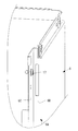
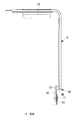
係止孔12は、リアパネル6の開口部側縁6Aの側縁部6Bに対して、上下方向の3箇所に設けられている。この複数の係止孔12の裏面側を覆うように、上下方向に延長された樋部材16を設け、リアパネル6の重ね合わせ部6Cに対して上下方向の複数箇所でネジ17によりネジ止め固定している。この樋部材16は、各係止孔12から浸入した雨水がそのまま機械室内に向って飛散しないように集約し、樋部材16に沿って下方へと流下させ、少なくとも水浸入を嫌う内部部品上に飛散する虞のない下方位置において排水可能とされている。
The locking holes 12 are provided at three locations in the vertical direction with respect to the
樋部材16は、鋼板をL字形に成形したもの、あるいは樹脂材をL字形の板状に成形したものであり、L字形の短辺側16Aで複数の係止孔12の裏面側を覆い、その長辺側16Bをリアパネル6の重ね合わせ部6Cに重ね合わせてネジ止め固定されている。これにより、複数の係止孔12の裏面側に、機械室内に対して遮蔽された適宜の大きさ、形状の空間18を形成し、その空間18を浸入した雨水を下方側に流下する流路としている。
The
なお、上記においては、リアパネル6の係止孔12の裏面側に樋部材16を設けた例について説明したが、必要に応じてフロントパネル5側の係止孔(図示省略)の裏面側に同様に樋部材を設けてもよいことはもちろんである。
In the above description, the example in which the
以上に説明の構成により、本実施形態によれば、以下の作用効果を奏する。
室外ユニット1のサービスパネル10は、その着脱によって筐体8内の機械室側に配設されている制御ボックスを始めとする室外側機器類の保守点検サービスを行うためのものであり、爪固定方式を採用することによって、ネジ止め箇所を最小限としてサービス性を向上させている。
With the configuration described above, according to the present embodiment, the following operational effects can be obtained.
The
このように、サービスパネル10の設置を爪固定方式とした場合、雨天時等にサービスパネル10側の係止爪13が係止されるリアパネル6あるいはフロントパネル5側の係止孔12の隙間から、雨水が浸入する虞がある。特に、機械室は、熱交換器室側に設けられている室外送風機の吸引作用により負圧となっていることから、パネル表面を伝う雨水が係止孔12から内部に吸引されて浸入し易くなる。
As described above, when the
然るに、本実施形態においては、複数の係止孔12が設けられているリアパネル6あるいはフロントパネル5開口部側縁6A,5Aの裏面側に、複数の係止孔12の裏面側を覆う上下方向に延長された樋部材16を設け、係止孔12からの浸入水を樋部材16に沿って流下させ、少なくとも水浸入を嫌う電装部品等の内部部品に飛散されることのない下方位置において、筐体8の内部または外部に排水するようにしている。
However, in the present embodiment, the
このため、係止孔12から浸入した雨水が、水の浸入を嫌う電装部品等に飛散される事態を防止し、水の浸入に起因する故障や制御不良等のトラブルの発生を解消することができる。また、防水対策として上下複数の係止孔12を跨ぐように、その裏面側に上下方向に延長された1つの樋部材16を設けるだけでよく、防水構造の簡素化およびその組み付け作業の容易化を図り、低コスト化を実現して恒久的な防水対策とすることができる。
For this reason, it is possible to prevent a situation in which rainwater that has entered from the locking
また、樋部材16が、係止孔12の裏面側に、浸入水を流下させることができる任意の形状および大きさの空間18を形成する部材とされているため、複数の係止孔12から浸入した雨水を樋部材16により形成された任意の形状、大きさの空間18を経て下方へと流下させ、その下端から筐体8の内部または外部に排水することができる。また、樋部材16によって形成される空間18の形状、大きさは、複数の係止孔12から浸入する微量の雨水を流下させるだけの単純でかつ小さなものでよく、従って、樋部材16そのものの構成を単純化し、低コスト化することができる。
Further, since the
さらに、本実施形態においては、樋部材16を鋼板製もしくは樹脂板製としている。このため、係止孔12の隙間を、インシュレーションを貼り付けて塞いだ構成としたもののように、接着面が剥がれ、あるいはそれ自身が経年劣化したりする心配がなく、恒久的な防水対策とすることができる。従って、時間の経過に伴う水浸入のリスクの高まり等をも解消することができる。
Furthermore, in this embodiment, the
[その他実施形態]
(1)上記実施形態では、樋部材16に沿って流下された雨水を、水の浸入を嫌う電装部品等の内部部品に飛散されることのない下方位置において、筐体8の内部または外部に排水するようにしているが、樋部材16の下端を筐体8の底面に形成されているドレンパンの直上位置まで延長して設けてもよい。
このように、樋部材16をドレンパンの直上位置まで延長して設けることにより、複数の係止孔12から浸入した雨水を、樋部材16によりドレンパン上に導いて排水処理することができる。従って、複数の係止孔12から浸入した雨水が内部部品上や筐体8の外部に飛散するのを確実に防止し、適切に処理することができる。
[Other embodiments]
(1) In the above-described embodiment, the rainwater flowing down along the
Thus, by providing the
(2)樋部材16を最下方に位置する係止孔12の下部位置で閉鎖部材により下端部を閉鎖した構成となし、樋部材16に沿って流下した浸入水を最下方に位置する係止孔12から排水するようにしてもよい。
上記構成となし、上方に位置する係止孔12から浸入した雨水を樋部材16に沿って最下方の係止孔12の位置まで流下させ、その雨水を樋部材16の下端部を閉鎖する閉鎖部材上に集め、そこから最下方の係止孔12を介して筐体8の内部または外部に排水することによっても、水の浸入を嫌う電装品上に雨水が飛散するのを防止することができる。
(2) The bottom end portion of the
The above-described configuration is adopted in which rainwater that has entered from the
この場合、樋部材16の下端部を閉鎖部材で閉鎖することにより、その内部空間18の負圧化を抑えることができ、係止孔12からの雨水の浸入を抑制することができる。これによって、樋部材16を設ける範囲を最小限となし、その小型化、低コスト化を図ることができるとともに、防水効果を高めることができる。
In this case, by closing the lower end portion of the
(3)さらに、上記(2)における閉鎖部材を、独立気泡の発泡樹脂材により構成することができる。このように、閉鎖部材を独立気泡の発泡樹脂材とすることにより、樋部材16の下端部を隙間が生じないように閉鎖することができるとともに、閉鎖部材自体による水の吸収を防止することができる。このため、樋部材16の下端部の閉鎖効果を向上することができるとともに、水を吸収することによる閉鎖部材の劣化を防ぐことができる。
(3) Further, the closing member in the above (2) can be formed of a closed cell foamed resin material. In this way, by using the closed cell foamed resin material as the closing member, the lower end portion of the
(4)上記の実施形態では、樋部材16をL字断面形状とした鋼板製もしくは樹脂板製の部材としているが、L字断面形状のものに限らず、係止孔12の裏面側に、浸入水を流下させることができる適宜大きさ、形状の空間18を形成し得るものであれば、如何なる形状あるいは材質の部材を用いてもよく、例えば、剛性部材に限らず、柔軟性を有するような部材としてもよいことはもちろんである。
(4) In the above embodiment, the
なお、本発明は、上記実施形態にかかる発明に限定されるものではなく、その要旨を逸脱しない範囲において、適宜変形が可能である。例えば、上記実施形態では、係止爪13および係止孔12の数を左右両端の上下方向に3箇所設けた例について説明したが、これら係止爪13および係止孔12の数は、サービスパネル10の大きさ等に対応させて適宜増減すればよい。
In addition, this invention is not limited to the invention concerning the said embodiment, In the range which does not deviate from the summary, it can change suitably. For example, in the above-described embodiment, the example in which the number of the locking
また、上記実施形態では、筐体8の前面から側面にかけてのフロントパネル5のコーナー部に保守点検用の開口部9を設け、その開口部9にL字断面形状のサービスパネル10を着脱自在に設置した例について説明したが、開口部9の位置は、必ずしもコーナー部である必要はなく、従って、サービスパネル10もL字断面形状である必要はなく、開口部9を他の位置に設け、サービスパネル10をそれに対応した形状のものとしてもよいことはもちろんである。
Moreover, in the said embodiment, the
1 室外ユニット
5 フロントパネル(外面パネル)
5A 開口部側縁
6 リアパネル(外面パネル)
6A 開口部側縁
8 筐体
9 保守点検用の開口部
10 サービスパネル
12 係止孔
13 係止爪
16 樋部材
18 空間
1
5A
6A Opening side edge 8
Claims (7)
前記開口部側縁に沿って上下方向に延長して設けられる樋部材を備え、
前記樋部材が、前記開口部側縁の裏面側から前記複数の係止孔の裏面側を、前記筐体の内部の他の空間から隔離するように覆うことにより、前記係止孔からの浸入水を前記樋部材に沿って流下させ、少なくとも水浸入を嫌う内部部品に飛散される虞のない下方位置において排水可能な構成とされていることを特徴とする空気調和機の室外ユニット。 An opening for maintenance / inspection is provided on one surface of the outer panel of the housing, and the service panel is locked to the upper and lower locking holes provided at the opening side edge of the outer panel with respect to the opening. In the outdoor unit of the air conditioner that is detachably provided by locking
Provided with a flange member provided extending in the vertical direction along the side edge of the opening,
The flange member covers the back surface side of the plurality of locking holes from the back surface side of the opening side edge so as to be isolated from other spaces inside the housing, thereby entering the locking holes. An outdoor unit for an air conditioner, characterized in that water is allowed to flow down along the eaves member and can be drained at a lower position where there is no risk of splashing to at least internal parts that dislike water intrusion.
前記開口部側縁に沿って上下方向に延長して設けられる樋部材を備え、 Provided with a flange member provided extending in the vertical direction along the side edge of the opening,
前記樋部材が、前記開口部側縁の裏面側から前記複数の係止孔の裏面側を覆うことにより、前記係止孔からの浸入水を前記樋部材に沿って流下させ、少なくとも水浸入を嫌う内部部品に飛散される虞のない下方位置において排水可能な構成とされ、最下方に位置する前記係止孔の下部位置で閉鎖部材により下端部が閉鎖され、流下した浸入水が最下方に位置する前記係止孔から排水される構成とされていることを特徴とする空気調和機の室外ユニット。 The flange member covers the back surface side of the plurality of locking holes from the back surface side of the opening side edge, thereby causing the intrusion water from the locking holes to flow down along the flange member, and at least water intrusion. It is configured to be able to drain at a lower position where there is no risk of being scattered by disliked internal parts, the lower end portion is closed by a closing member at the lower position of the locking hole located at the lowermost position, and the infiltrated water that has flowed down is at the lowermost position. It is set as the structure drained from the said locking hole located, The outdoor unit of the air conditioner characterized by the above-mentioned.
Priority Applications (2)
| Application Number | Priority Date | Filing Date | Title |
|---|---|---|---|
| JP2013144516A JP5968271B2 (en) | 2013-07-10 | 2013-07-10 | Air conditioner outdoor unit |
| EP14175373.1A EP2840326A1 (en) | 2013-07-10 | 2014-07-02 | Air conditioner outdoor unit |
Applications Claiming Priority (1)
| Application Number | Priority Date | Filing Date | Title |
|---|---|---|---|
| JP2013144516A JP5968271B2 (en) | 2013-07-10 | 2013-07-10 | Air conditioner outdoor unit |
Publications (3)
| Publication Number | Publication Date |
|---|---|
| JP2015017740A JP2015017740A (en) | 2015-01-29 |
| JP2015017740A5 JP2015017740A5 (en) | 2015-07-30 |
| JP5968271B2 true JP5968271B2 (en) | 2016-08-10 |
Family
ID=51167654
Family Applications (1)
| Application Number | Title | Priority Date | Filing Date |
|---|---|---|---|
| JP2013144516A Active JP5968271B2 (en) | 2013-07-10 | 2013-07-10 | Air conditioner outdoor unit |
Country Status (2)
| Country | Link |
|---|---|
| EP (1) | EP2840326A1 (en) |
| JP (1) | JP5968271B2 (en) |
Cited By (1)
| Publication number | Priority date | Publication date | Assignee | Title |
|---|---|---|---|---|
| CN108592247A (en) * | 2018-04-28 | 2018-09-28 | 广东美的暖通设备有限公司 | Air-conditioner outdoor unit and air conditioner with it |
Families Citing this family (7)
| Publication number | Priority date | Publication date | Assignee | Title |
|---|---|---|---|---|
| JP2017138075A (en) * | 2016-02-05 | 2017-08-10 | 三菱重工業株式会社 | Air conditioner |
| CN105972716B (en) * | 2016-06-23 | 2020-09-04 | 珠海格力电器股份有限公司 | Sheet metal part connecting structure and air conditioner outdoor unit |
| MY185822A (en) * | 2016-08-12 | 2021-06-11 | Daikin Res & Development Malaysia Sdn Bhd | Service panel of an air conditioner |
| JP6531795B2 (en) | 2017-07-31 | 2019-06-19 | ダイキン工業株式会社 | Outdoor unit of refrigeration system |
| WO2020012527A1 (en) * | 2018-07-09 | 2020-01-16 | 三菱電機株式会社 | Outdoor unit for air-conditioning device |
| AU2020431597B2 (en) * | 2020-02-26 | 2024-01-25 | Mitsubishi Electric Corporation | Outdoor unit for air conditioner |
| JP2022187051A (en) * | 2021-06-07 | 2022-12-19 | パナソニックIpマネジメント株式会社 | heat pump heat source machine |
Family Cites Families (12)
| Publication number | Priority date | Publication date | Assignee | Title |
|---|---|---|---|---|
| US3915530A (en) * | 1974-09-18 | 1975-10-28 | Westinghouse Electric Corp | Insertable filler arrangement for reducing opening size |
| JPH08178360A (en) * | 1994-12-20 | 1996-07-12 | Fujitsu General Ltd | Outdoor machine for air-conditioner |
| JP3326585B2 (en) * | 1995-11-24 | 2002-09-24 | 松下電器産業株式会社 | Air conditioner |
| US6354936B1 (en) * | 1998-08-10 | 2002-03-12 | Lg Electronics Inc. | Opening-closing structure of an inlet grille in an air conditioner |
| JP3019850B1 (en) * | 1998-11-13 | 2000-03-13 | ダイキン工業株式会社 | Outdoor unit of air conditioner |
| JP4559326B2 (en) * | 2005-09-13 | 2010-10-06 | 三菱電機株式会社 | Air conditioner outdoor unit |
| WO2007086640A2 (en) * | 2006-01-26 | 2007-08-02 | Lg Electronics Inc. | Indoor unit of air conditioner |
| JP2007247984A (en) * | 2006-03-16 | 2007-09-27 | Matsushita Electric Ind Co Ltd | Outdoor unit for air conditioner |
| JP5058004B2 (en) * | 2008-01-28 | 2012-10-24 | 三菱電機株式会社 | Outdoor unit and air conditioner equipped with the same |
| JP2009250459A (en) * | 2008-04-02 | 2009-10-29 | Panasonic Corp | Outdoor unit of air conditioner |
| JP5402851B2 (en) | 2010-06-23 | 2014-01-29 | 株式会社富士通ゼネラル | Air conditioner outdoor unit |
| JP5252069B2 (en) * | 2011-12-26 | 2013-07-31 | パナソニック株式会社 | Air conditioner outdoor unit |
-
2013
- 2013-07-10 JP JP2013144516A patent/JP5968271B2/en active Active
-
2014
- 2014-07-02 EP EP14175373.1A patent/EP2840326A1/en not_active Withdrawn
Cited By (1)
| Publication number | Priority date | Publication date | Assignee | Title |
|---|---|---|---|---|
| CN108592247A (en) * | 2018-04-28 | 2018-09-28 | 广东美的暖通设备有限公司 | Air-conditioner outdoor unit and air conditioner with it |
Also Published As
| Publication number | Publication date |
|---|---|
| JP2015017740A (en) | 2015-01-29 |
| EP2840326A1 (en) | 2015-02-25 |
Similar Documents
| Publication | Publication Date | Title |
|---|---|---|
| JP5968271B2 (en) | Air conditioner outdoor unit | |
| US8864560B2 (en) | Water-blocking vent panel and air filter therefor | |
| JP2015017740A5 (en) | ||
| JP2007173330A (en) | Louver | |
| JP2010129846A (en) | Electronic equipment device | |
| WO2009144778A1 (en) | Ventilator | |
| JP4670441B2 (en) | Ventilation equipment | |
| WO2020037875A1 (en) | Control box and controller assembly having same, and air conditioner outdoor unit | |
| JP6410211B2 (en) | Embedded ceiling air conditioner | |
| US20070227172A1 (en) | Air Conditioner | |
| JP2000139006A (en) | Outdoor enclosed switchboard | |
| JP5169592B2 (en) | Ventilation equipment | |
| JP5219213B2 (en) | Inter-rack passage shielding structure | |
| JP6584922B2 (en) | Blower | |
| JP6719814B2 (en) | Louver ventilation system | |
| JP6434151B2 (en) | Ventilation fan | |
| JP6929472B2 (en) | Bathroom Dryer | |
| JP5507160B2 (en) | Wall-mounted air conditioner | |
| JP2021128968A (en) | Ventilator for electrical apparatus housing cabinet | |
| CN205208778U (en) | Air condensing units protector , air condensing units shell and air conditioning system | |
| JP6203216B2 (en) | Intake duct section of engine-driven work machine | |
| EP3029392B1 (en) | Stabilizing and sealing arrangement | |
| JP6145865B2 (en) | Ceiling suspended air conditioner | |
| JP4681525B2 (en) | Intake hood for engine generator | |
| CN219735469U (en) | Air conditioner assembly |
Legal Events
| Date | Code | Title | Description |
|---|---|---|---|
| A521 | Written amendment |
Free format text: JAPANESE INTERMEDIATE CODE: A523 Effective date: 20150611 |
|
| A621 | Written request for application examination |
Free format text: JAPANESE INTERMEDIATE CODE: A621 Effective date: 20150611 |
|
| A977 | Report on retrieval |
Free format text: JAPANESE INTERMEDIATE CODE: A971007 Effective date: 20151008 |
|
| A131 | Notification of reasons for refusal |
Free format text: JAPANESE INTERMEDIATE CODE: A131 Effective date: 20151104 |
|
| A521 | Written amendment |
Free format text: JAPANESE INTERMEDIATE CODE: A523 Effective date: 20160104 |
|
| TRDD | Decision of grant or rejection written | ||
| A01 | Written decision to grant a patent or to grant a registration (utility model) |
Free format text: JAPANESE INTERMEDIATE CODE: A01 Effective date: 20160607 |
|
| A61 | First payment of annual fees (during grant procedure) |
Free format text: JAPANESE INTERMEDIATE CODE: A61 Effective date: 20160705 |
|
| R151 | Written notification of patent or utility model registration |
Ref document number: 5968271 Country of ref document: JP Free format text: JAPANESE INTERMEDIATE CODE: R151 |
|
| S111 | Request for change of ownership or part of ownership |
Free format text: JAPANESE INTERMEDIATE CODE: R313111 |
|
| R350 | Written notification of registration of transfer |
Free format text: JAPANESE INTERMEDIATE CODE: R350 |